ANSYS, Inc. Proprietary© 2006 ANSYS, Inc.
Interface Procedure for Magnetic Edge Elements
Interface Procedure for Magnetic Edge ElementsInterface Procedure for Magnetic Edge Elements
Frank WeiandMartin HankeJens OttoCADFEM GmbH
ANSYS, Inc. Proprietary© 2006 ANSYS, Inc.
Interface Procedure for Magnetic Edge Elements
Content1. Overview2. Magnetic Flux Interface Condition3. Interface Procedure 4. Element Flux Edge Contribution – Master (Step 1)5. Point to Slave Area Contribution (Step 2)6. Slave Surface Gauging (Step 3)7. Point to Master Element Contribution (Step 4)8. Constraint Equation Definition 9. Complete Interface Procedure 2-BLOCK Test (static)10. Complete Interface Procedure MAG-CIRC (static)11. Complete Interface Procedure MAG-CIRC MIXED BC (static)12. Complete Interface Procedure MAG-CIRC MIXED BC (transient)13. Complete Interface Procedure MAG-CIRC MIXED BC MOTION (transient)14. Complete Interface Procedure SMALL MAG-CIRC MIXED BC MOTION (transient)15. Complete Interface Procedure Linear Actuator MOTION (transient)16. - 21. Complete Interface Procedure Linear Actuator MOTION vs- VxB
ANSYS, Inc. Proprietary© 2006 ANSYS, Inc.
Interface Procedure for Magnetic Edge Elements
A magnetic Interface Procedure for the Magnetic EDGE Elements (117) in ANSYS is needed to:
• Connect dissimilar meshes within 3D Magnetic Field Simulation
• Allow relative motion in transient analysis problems without thelimitation of SOLID97 to calculate eddy currents
This allows a more complete simulation of electrical devices as:
• Induction machines• Generators• Velocity sensors
1. Overview
ANSYS, Inc. Proprietary© 2006 ANSYS, Inc.
Interface Procedure for Magnetic Edge Elements
Magnetic induction must be continuous on an Air-Air interface at each point:
Assumption:Magnetic flux is constant inside black surface
Therefore:The Magnetic flux passing trough black surface could be derived from the magnetic flux trough the blue surface (mainly depends on area relation)
)2(__
__ * blacka
bluea
blackabluea A
AΦ=Φ
)1(__ blueredblackred BBrr
=
Φ
Br
2. Magnetic Flux Interface Condition
ANSYS, Inc. Proprietary© 2006 ANSYS, Inc.
Interface Procedure for Magnetic Edge Elements
2.1 What are the DOFs of Edge Elements?ANSYS MAGNETIC EDGE ELEMENT 117:
Magnetic Flux through an element face is defined by the sum of the corresponding edge potentials (DOF AZ) along the edge directions. The direction is considered by the sign.
Or:
This means: Because of the sign, you must not use couplings (CPs) even if you have a similar mesh on both sides of the interface!
AZ1AZ2
AZ3AZ4
EF
Φ
)3(__ * ∑=ΦEdges
EdgeZfaceelement AEdgesign
ANSYS, Inc. Proprietary© 2006 ANSYS, Inc.
Interface Procedure for Magnetic Edge Elements
3.1 Similar Meshes: Using Couplings???
Discontinuous but similar Mesh with CP Interface
Continuous Mesh with Dirichlet BC to get a 45° B-Vector
Error: 50%coupled nodesat interface (CPINTF)
ANSYS, Inc. Proprietary© 2006 ANSYS, Inc.
Interface Procedure for Magnetic Edge Elements
3.2 Similar Meshes: Use Constraint Equations!To get good results we have to consider the edge direction.For all Elements-Faces at the interface:
where: e - is the Element numberm - is the MSN (mid side node) number
{ } [ ] { }
[ ] { } )4(
...1
..1
*,
*)(
mZ
mZme
e
Ame
A
I
signIndex
=
=Φ
AZ1AZ2
AZ3AZ4
EF
Φ
ANSYS, Inc. Proprietary© 2006 ANSYS, Inc.
Interface Procedure for Magnetic Edge Elements
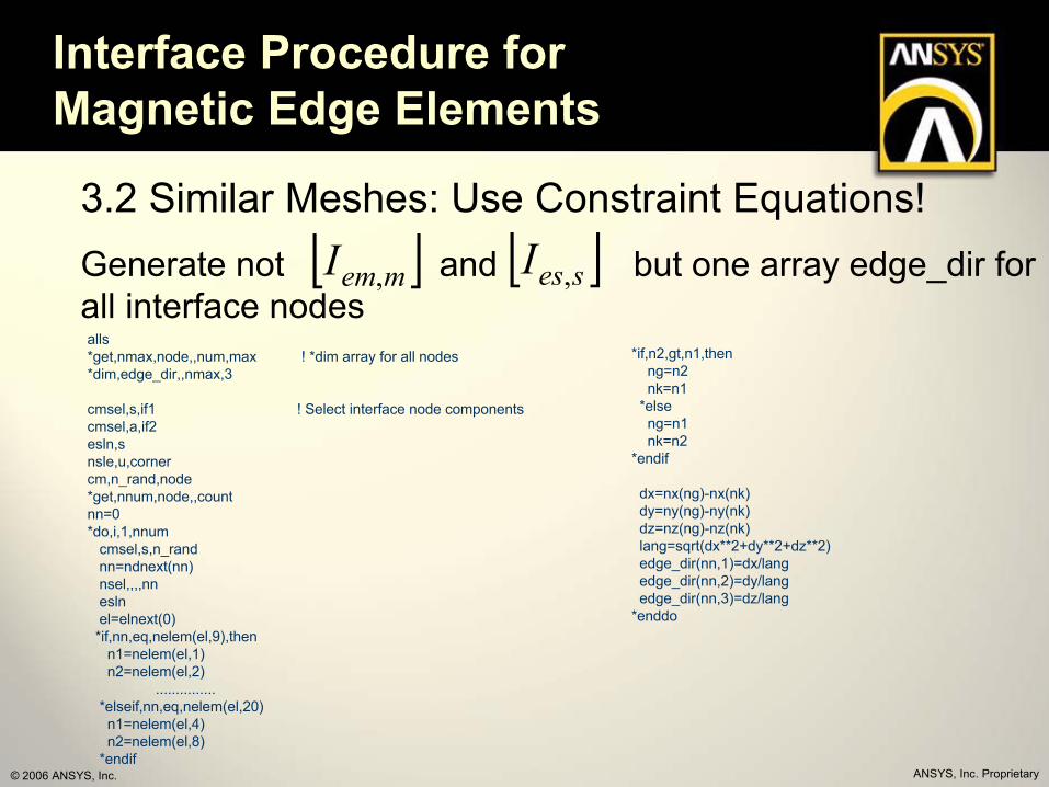
3.2 Similar Meshes: Use Constraint Equations!First the edge directions have to be retrieved and saved as a sign (+1 or -1) in an array for both sides of the interface.
The magnetic Flux at the master side is defined by:
where: em - is the Element number at the masterm - is the MSN (mid side node) number at the master
and therefore at the slave side:
where: es - is the Element number at the slaves - is the MSN (mid side node) number at slave
{ } [ ] { } )5(*, mZem AmemI=Φ
{ } [ ] { } )6(*, sZes AsesI=Φmaster sideat interface
slave sideat interface
ANSYS, Inc. Proprietary© 2006 ANSYS, Inc.
Interface Procedure for Magnetic Edge Elements
3.2 Similar Meshes: Use Constraint Equations!Generate not and but one array edge_dir for all interface nodes
[ ]memI , [ ]sesI ,
*if,n2,gt,n1,thenng=n2nk=n1
*elseng=n1nk=n2
*endif
dx=nx(ng)-nx(nk)dy=ny(ng)-ny(nk)dz=nz(ng)-nz(nk)lang=sqrt(dx**2+dy**2+dz**2)edge_dir(nn,1)=dx/langedge_dir(nn,2)=dy/langedge_dir(nn,3)=dz/lang
*enddo
alls*get,nmax,node,,num,max ! *dim array for all nodes*dim,edge_dir,,nmax,3
cmsel,s,if1 ! Select interface node componentscmsel,a,if2esln,snsle,u,cornercm,n_rand,node*get,nnum,node,,countnn=0*do,i,1,nnum
cmsel,s,n_randnn=ndnext(nn)nsel,,,,nneslnel=elnext(0)*if,nn,eq,nelem(el,9),then
n1=nelem(el,1)n2=nelem(el,2)
...............*elseif,nn,eq,nelem(el,20)n1=nelem(el,4)n2=nelem(el,8)
*endif
ANSYS, Inc. Proprietary© 2006 ANSYS, Inc.
Interface Procedure for Magnetic Edge Elements
3.2 Similar Meshes: Use Constraint Equations!Then the Constraint Equations are generated. With similar meshes the element faces have the same area and are at the same position:
{ } [ ] [ ] { }ZmsZ AmemT
sesA II *,*,=
{ } { }emes Φ=Φ
[ ] { } [ ] { }ZmsZ AmemAses II *,*, =
ANSYS, Inc. Proprietary© 2006 ANSYS, Inc.
Interface Procedure for Magnetic Edge Elements
3.2 Similar Meshes: Use Constraint Equations!The results are the same as with a continuous mesh:
Discontinuous but similar Mesh with Constraint Equations Interface
nodes coupled by constraintequations at interface
ANSYS, Inc. Proprietary© 2006 ANSYS, Inc.
Interface Procedure for Magnetic Edge Elements
3.2.1 Example using ANSYS WorkbenchThe procedure has been implemented as a command object in the ANSYS Workbench environment. This shows the following example of a motor.
ANSYS, Inc. Proprietary© 2006 ANSYS, Inc.
Interface Procedure for Magnetic Edge Elements
3.2.1 Example using ANSYS WorkbenchIn DesignModeler two single parts have to be generated, one for the inner parts (rotor) and one for the outer parts (stator).
ANSYS, Inc. Proprietary© 2006 ANSYS, Inc.
Interface Procedure for Magnetic Edge Elements
3.2.1 Example using ANSYS WorkbenchAt the interface region we need the same mesh. So ‘hard’ line divisions are defined at the circumferential lines and also on the lines parallel to the axis of the motor.
ANSYS, Inc. Proprietary© 2006 ANSYS, Inc.
Interface Procedure for Magnetic Edge Elements
3.2.1 Example using ANSYS WorkbenchTo access the interface region from the commands object the interface areas are put into ‘Named Selections’, one for the inner interface areas and one for the outer interface areas.
ANSYS, Inc. Proprietary© 2006 ANSYS, Inc.
Interface Procedure for Magnetic Edge Elements
3.2.1 Example using ANSYS WorkbenchThen the commands object is inserted. The ‘Named Selections’ come to the ANSYS solver as node components.
ANSYS, Inc. Proprietary© 2006 ANSYS, Inc.
Interface Procedure for Magnetic Edge Elements
3.2.1 Example using ANSYS WorkbenchSolving the model gives a continuous magnetic flux density from the inner to the outer region.
ANSYS, Inc. Proprietary© 2006 ANSYS, Inc.
Interface Procedure for Magnetic Edge Elements
4.1 Dissimilar MeshesThe procedure can be extended to dissimilar meshes. The assumption of the Edge Flux Elements (SOLID117) is a constant magnetic flux through the elements face. Connecting regions with dissimilar meshes, the ratio of the areas on both sides must be considered. The Magnetic flux passing trough black surface could be derived from the magnetic flux trough the blue surface .
Φ
Br
blackabluea
blackabluea A
A_
_
__ *Φ=Φ
blueredblackred BB __
rr=
ANSYS, Inc. Proprietary© 2006 ANSYS, Inc.
Interface Procedure for Magnetic Edge Elements
4.1 Dissimilar Meshes
The magnetic Flux at the master side is defined by:
where: em - is the Element number at the masterm - is the MSN (mid side node) number at the master
and therefore at the slave side:
where: es - is the Element number at the slaves - is the MSN (mid side node) number at slave
With the induction at a known Point P follows:
where: P - is the Point numberF – is the Area (Element Area at Interface where Flux is constant)
{ } [ ] { } )5(*, mZem AmemI=Φ
master sideat interface
slave sideat interface(finer mesh)
{ } [ ] { } )6(*, sZes AsesI=Φ
P
{ } [ ] { } )7(*, Pes BPesF=Φ
ANSYS, Inc. Proprietary© 2006 ANSYS, Inc.
Interface Procedure for Magnetic Edge Elements
4.1 Dissimilar MeshesThe induction at a known Point P could be derived from the master side Flux as:
Together with (7) and (5) the Flux at the slave side is given by:
Using this equation and (6) the Flux and the edge potential AZ at the slave side could be derived from the master side.
master sideat interface
slave sideat interface(finer mesh)
{ } [ ] [ ] { } )8(1**, emP ememPB FI Φ=
−P
{ } [ ] [ ] [ ] [ ] { }Zmes AmemememPPes IFIF *,**,*,1−
=Φ
ANSYS, Inc. Proprietary© 2006 ANSYS, Inc.
Interface Procedure for Magnetic Edge Elements
4.1 Dissimilar MeshesA solution method in ANSYS is developed with the following steps:
{ } [ ] [ ] [ ] [ ] { }Zmes AmemememPPes IFIF *,**,*,1−
=Φ
{ } [ ] { }sZes AsesI *,=Φ
fixfix
fix
update
Step 1Step 2
Step 3
Step 4
Gauging
Constraint Equation (CE) Master-Slave
ANSYS, Inc. Proprietary© 2006 ANSYS, Inc.
Interface Procedure for Magnetic Edge Elements
4.1.1 Element Flux Edge Contribution – Master (Step 1)Generate:
Surface Elements (mesh200) are used to determine the element area for all faces at the master side. Index fields help to minimize the field length.
Edge Direction Index Matrix is generated using the I-J-K-L-M-N-O-Pinformation of the surface elements.
[ ] [ ] [ ] )10(1
,*, mememmem IFK −=
*dim,K_em_m,array,em_num,m_num ! inverse area direction matrixnsle*do,ie,1+e_off1,e_off2*do,im,1,4*if,nelem(ie,im),eq,nelem(ie,mod(im,4)+1),then ! 3 sided
*cycle ! skip*endif ! 4 sided!I_em_m(ie-e_off1,index_mi(nelem(ie,im+4)))=sign(1,nelem(ie,mod(im,4)+1)-nelem(ie,im))!K_em_m(ie-e_off1,index_mi(nelem(ie,im+4)))=I_em_m(ie-e_off1,index_mi(nelem(ie,im+4)))/F_em(ie-e_off1)K_em_m(ie-e_off1,index_mi(nelem(ie,im+4)))=sign(1,nelem(ie,mod(im,4)+1)-nelem(ie,im))/F_em(ie-e_off1)
*enddo*enddo
*dim,index_im,,m_num ! index vector im*dim,index_mi,,nmax ! index vector minn=0
*do,i,1,m_numnn=ndnext(nn) ! master numberindex_im(i)=nn ! index vectorindex_mi(nn)=i*enddo
ANSYS, Inc. Proprietary© 2006 ANSYS, Inc.
Interface Procedure for Magnetic Edge Elements
4.1.2 Point to Slave Area Contribution (Step 2)Generate:
As the Points are used to prescribe the slave area information each slave element is subdivided into regions that are represented by these points:
[ ]PesF ,*dim,F_es_p,array,es_num,p_num ! point area contributions to slave*dim,xyz_p,array,p_num,3 ! point coordinatescmsel,s,elem4nsle ip=0 ! point index
*do,ie,e_off2+1,e_off3*if,_return,gt,0,exit*get,ncx,elem,ie,cent,x*get,ncy,elem,ie,cent,y*get,ncz,elem,ie,cent,z*do,im,1,4*if,nelem(ie,im),eq,nelem(ie,mod(im,4)+1),then*cycle
*endifnx1=nx(nelem(ie,im))ny1=ny(nelem(ie,im))nz1=nz(nelem(ie,im))nx2=nx(nelem(ie,mod(im,4)+1))ny2=ny(nelem(ie,mod(im,4)+1))nz2=nz(nelem(ie,mod(im,4)+1))vpx=(ny1-ncy)*(nz2-ncz)-(nz1-ncz)*(ny2-ncy) vpy=(nz1-ncz)*(nx2-ncx)-(nx1-ncx)*(nz2-ncz) vpz=(nx1-ncx)*(ny2-ncy)-(ny1-ncy)*(nx2-ncx) artri=sqrt(vpx**2+vpy**2+vpz**2)/2/p_div**2 ! small triangle areaSUBROUTINE A INCLUDED
*enddo*enddo
ANSYS, Inc. Proprietary© 2006 ANSYS, Inc.
Interface Procedure for Magnetic Edge Elements
4.1.2 Point to Slave Area Contribution (Step 2)These triangular regionsare used to create pointlocations (one for eachtriangle) to be associatedwith a master element later.
SUBROUTINE A
*do,i1,1,p_div*do,i2,1,p_div-i1+1ip=ip+1xyz_p(ip,1)=((i1-2/3)*(nx2-nx1)+(i2-2/3)*(ncx-nx1))/p_div+nx1xyz_p(ip,2)=((i1-2/3)*(ny2-ny1)+(i2-2/3)*(ncy-ny1))/p_div+ny1xyz_p(ip,3)=((i1-2/3)*(nz2-nz1)+(i2-2/3)*(ncz-nz1))/p_div+nz1!n,,xyz_p(ip,1),xyz_p(ip,2),xyz_p(ip,3)F_es_p(ie-e_off2,ip)=artri *if,i1+i2,lt,p_div+1,thenip=ip+1xyz_p(ip,1)=((i1-1/3)*(nx2-nx1)+(i2-1/3)*(ncx-nx1))/p_div+nx1xyz_p(ip,2)=((i1-1/3)*(ny2-ny1)+(i2-1/3)*(ncy-ny1))/p_div+ny1xyz_p(ip,3)=((i1-1/3)*(nz2-nz1)+(i2-1/3)*(ncz-nz1))/p_div+nz1!n,,xyz_p(ip,1),xyz_p(ip,2),xyz_p(ip,3)F_es_p(ie-e_off2,ip)=artri
*endif*enddo
*enddoP
ANSYS, Inc. Proprietary© 2006 ANSYS, Inc.
Interface Procedure for Magnetic Edge Elements
4.1.3 Slave Surface Gauging (Step 3)Generate:
Surface Elements (mesh200) are used to determine the element area for all faces at the slave side. Index fields help to minimize the field length.
*dim,I_es,array,e_num,s_num ! direction index matrix element - slave edge
/com,===========================================================/com,Fill direction index matrix/com,===========================================================cmsel,s,elem4nsle ! select corner nodes also*do,elem,1+e_off1,e_off2 ! loop over alls slave elements*do,is,1,4 ! loop over all edges each slave element*if,nelem(elem,is),eq,nelem(elem,mod(is,4)+1),then ! 3 sided*cycle ! skip
*endif ! 4 sidedI_es(elem-e_off1,index_si(nelem(elem,is+4)))=sign(1,nelem(elem,mod(is,4)+1)-nelem(elem,is))
*enddo*enddo
[ ]sesI ,
ANSYS, Inc. Proprietary© 2006 ANSYS, Inc.
Interface Procedure for Magnetic Edge Elements
4.1.3 Slave Surface Gauging (Step 3)Generate:
A tree search method is needed to determine a unique set of edges defining the slave element flux (later derived using constraint equations).
First checking the prescribes dirichle’t boundary conditionsat external nodes
/com,==================================================/com,Start definition for interface tree search/com,==================================================cmsel,s,node4nsel,r,d,az,-1e12,1e12nn=ndnext(0)*if,nn,eq,0,thencmsel,s,elem4nslensel,r,extnsle,u,cornernn=ndnext(0) ! no D at all
*endifnsel,,,,nncmsel,s,elem4esln,re_act=elnext(0)-e_off1 ! tree start element indexcmsel,s,elem4cmsel,s,node4istart=1 ! begin tree search at istart
{ }esTree AZ1AZ2
AZ3AZ4
ANSYS, Inc. Proprietary© 2006 ANSYS, Inc.
Interface Procedure for Magnetic Edge Elements
4.1.3 Slave Surface Gauging (Step 3)Generate:
Starting from an arbitrary node(msn slave side) the next freeedge at the next element is searched (and marked withinthe Tree)
Used Fields:
Tree_es and nf (nodal flag field)
/com,===================================================/com,Interface Tree Search/com,===================================================itree=1loop=1itree=1loop=es_num-1 ! number of tree branches*dowhile,loop ! tree loop
*abc,100*loop/es_num*if,_return,gt,0,exit ef(e_act)=1 ! indicate as treatedie=e_act+e_off2exit_found=0 ! flag if exit found*do,is,1,4 ! search for exit
*if,nelem(ie,is),eq,nelem(ie,mod(is,4)+1),then ! triangle top case*cycle
*endif*if,exit_found,eq,0,then
*if,nf(index_si(nelem(ie,is+4)),2),eq,0,thenn_exit=nelem(ie,is+4)*vscf,elem2,first,I_es_s(1,index_si(n_exit))*if,e_act,eq,elem2,then
*vscf,elem3,first,I_es_s(elem2+1,index_si(n_exit))elem2=elem3+elem2 ! elem2 is index of potential next element
*endif*if,ef(elem2),eq,0,then
e_act_neu=elem2 ! valid next elementnf(index_si(nelem(ie,is+4)),2)=3 ! mark CE nodeexit_found=1tree_es(itree,1)=e_acttree_es(itree,2)=e_act_neutree_es(itree,3)=index_si(nelem(ie,is+4))tree_es(itree,4)=nelem(ie,is+4)
*elsenf(index_si(nelem(ie,is+4)),2)=2 ! mark gauge node
*endif*endif
*endif*enddo
{ }esTree
Continues..
ANSYS, Inc. Proprietary© 2006 ANSYS, Inc.
Interface Procedure for Magnetic Edge Elements
4.1.3 Slave Surface Gauging (Step 3)Generate:
If no exit could be found from thecurrent element – it starts fromthe last known split point.
I check routine is provided to displaythe generated tree using new elements
*if,exit_found,eq,1,thene_act=e_act_neuitree=itree+1
*else e_act=tree_es(istart,1)itree=itreeistart=istart+1
*endifloop=es_num-itreee_act=e_act
*enddo
{ }esTreeContinues..
*cre,showtree,mac/prep7et,5,200et,6,21*get,nmax,node,,num,maxd*do,i,1,es_num-1
*get,x1,elem,tree_es(i,1)+e_off2,cent,x*get,y1,elem,tree_es(i,1)+e_off2,cent,y*get,z1,elem,tree_es(i,1)+e_off2,cent,z*get,x2,elem,tree_es(i,2)+e_off2,cent,x*get,y2,elem,tree_es(i,2)+e_off2,cent,y*get,z2,elem,tree_es(i,2)+e_off2,cent,zn,nmax+(i-1)*2+1,x1,y1,z1n,nmax+(i-1)*2+2,x2,y2,z2type,5e,nmax+(i-1)*2+1,nmax+(i-1)*2+2type,6e,tree_es(i,4)
*enddo
ANSYS, Inc. Proprietary© 2006 ANSYS, Inc.
Interface Procedure for Magnetic Edge Elements
4.1.4 Point to Master Element Contribution (Step 4)
Generate:
Using the Point location field (already defined in step 2) the associatedelement at the master side is found.
This undocumented function providesthe information fast and correct (tested within 9.0)
/prep7et,1,200,7rect,0,1,0,1lesi,all,,,3,10ames,allp=100
*dim,xyz,,p,3*do,i,1,pxyz(i,1)=rand(0,1)xyz(i,2)=rand(0,1)xyz(i,3)=0n,100+i,xyz(i,1),xyz(i,2)
*enddo*dim,elem,,p*dim,eloc,,p,3
*mop,eloc(1,1),xyz(1,1),INTP,elem(1)
[ ]emPI ,
*mop,eloc(1,1),xyz(1,1),INTP,elem(1)
ANSYS, Inc. Proprietary© 2006 ANSYS, Inc.
Interface Procedure for Magnetic Edge Elements
4.1.5 Constraint Equation DefinitionGenerate:
A backward working routineis used to define the master-slave constraints along theknown edge potentials of theslave elements.
The constraint slave nodeis placed at the first positionwithin the CE to allow a later(automatic) substitution during the element formulation
CE/com,=======================================================/com,Define Constraint Equations at Interface/com,=======================================================*do,ice,1,e_num-1
elem=tree_es(e_num-ice,2)+e_off1 ! tree backwards*get,y,elem,elem,cent,y*get,z,elem,elem,cent,z ns=tree_es(e_num-ice,4)ce,ice,,ns,az,1 ! reserve first position*do,is,1,4
*if,nelem(elem,is),eq,nelem(elem,mod(is,4)+1),then*cycle
*endifns=nelem(elem,is+4)ce,ice,,ns,az,sign(1,nelem(elem,mod(is,4)+1)-nelem(elem,is))
*enddofact=-1/(enum2/enum1)**2*if,y,gt,0,and,z,gt,0,then
ce,ice,,73,az,fact,56,az,factce,ice,,30,az,-fact,70,az,-fact
*endif*if,y,lt,0,and,z,gt,0,then
ce,ice,,71,az,-fact,70,az,factce,ice,,28,az,fact,48,az,-fact
*endif*if,y,gt,0,and,z,lt,0,then
ce,ice,,13,az,fact,54,az,-factce,ice,,73,az,-fact,74,az,fact
*endif*if,y,lt,0,and,z,lt,0,then
ce,ice,,11,az,-fact,74,az,-factce,ice,,71,az,fact,46,az,fact
*endif*enddo
ANSYS, Inc. Proprietary© 2006 ANSYS, Inc.
Interface Procedure for Magnetic Edge Elements
4.1.5 Constraint Equation DefinitionGenerate:
The marked (using field nf) edge nodes that are not usedwithin the tree are
a) Getting dirichlet BCb) Using the existing dirichlet BC
to reformulate the constant termof the constraint equation.
CE /com,===========================================================/com,Correct Constraint Equations (CE) where Dirichlet BC accurs/com,===========================================================*get,cemax,ce,,num,max*do,i,1,cemax
*get,nterm,ce,i,nterm*get,ceabs,ce,i,constit=0*do,iterm,1,nterm
it=it+1*get,nn,ce,i,term,it,node*get,daz,node,nn,d,az*if,abs(daz),lt,1e12,then
*get,cf,ce,i,term,it,coefce,i,,nn,az,0ceabs=ceabs-cf*dazit=it-1
*endif*enddocecm,i,ceabs
*enddo
ANSYS, Inc. Proprietary© 2006 ANSYS, Inc.
Interface Procedure for Magnetic Edge Elements
4.1.5 Constraint Equation DefinitionInput part: if_proc_test5.inp
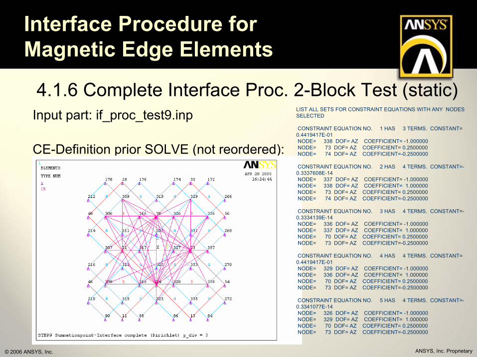
Using a prescribed tree – thisInput checks the CE-generation.
/com,===========================================================/com, CADFEM GmbH /com,-----------------------------------------------------------/com, Original file name: if_proc_test5.inp/com,===========================================================! Execution environment: ANSYS 9.0 SP1 MPHY! Operation system: W2K / XP 32! Language: APDL! File type: ANSYS command macro file! Unit system: SI! Created by: Martin Hanke, Jens Otto! Department: Service! Company: CADFEM! Release history | date | name | reason! Creation | 2005-4-18 | MH/JO | ! Modification | | |! First Release | | |! Modification | | |!===============================================================! Project name: G05-VOI-01! Parent file: none! Parameters: none! Called files none! Imported files: none!===============================================================! Short description:! !X!X! SIMPLE TEST MODEL (2 BLOCKS) FOR INTERFACE TEST !X!X!! !X!X! external bondary complete dirichlet specification !X!X!! !X!X! none material bondary / static / not moved !X!X!! !X!X! MAIN PURPOSE: !X!X!! !X!X! CE-INTERPOLATION (BACK TREE USE) !X!X!! !X!X! ANALYTICAL TREE USED !X!X!!===============================================================!===============================================================! Summary:! !X!X! BACKWARD Method for CE definition works !X!X!! !X!X! as long as slave node gets first CE postion !X!X!!===============================================================
ANSYS, Inc. Proprietary© 2006 ANSYS, Inc.
Interface Procedure for Magnetic Edge Elements
4.1.5 Constraint Equation DefinitionInput part: if_proc_test5.inp
Generated CE’s:
LIST ALL SETS FOR CONSTRAINT EQUATIONS WITH ANY NODES SELECTED
CONSTRAINT EQUATION NO. 1 HAS 3 TERMS. CONSTANT= 0.4419417E-01NODE= 335 DOF= AZ COEFFICIENT= 1.000000 NODE= 73 DOF= AZ COEFFICIENT= 0.2500000 NODE= 74 DOF= AZ COEFFICIENT=-0.2500000
CONSTRAINT EQUATION NO. 2 HAS 4 TERMS. CONSTANT= 0.000000 NODE= 325 DOF= AZ COEFFICIENT= 1.000000 NODE= 335 DOF= AZ COEFFICIENT= -1.000000 NODE= 73 DOF= AZ COEFFICIENT= 0.2500000 NODE= 74 DOF= AZ COEFFICIENT=-0.2500000
ANSYS, Inc. Proprietary© 2006 ANSYS, Inc.
Interface Procedure for Magnetic Edge Elements
4.1.6 Complete Interface Proc. 2-Block Test (static)Input part: if_proc_test9.inp
Simple 2-Block Structure with externalField excitation using dirichlet BC.
/com,===========================================================/com, CADFEM GmbH /com,-----------------------------------------------------------/com, Original file name: if_proc_test9.inp/com,===========================================================! Execution environment: ANSYS 9.0 SP1 MPHY! Operation system: W2K / XP 32! Language: APDL! File type: ANSYS command macro file! Unit system: SI! Created by: Martin Hanke, Jens Otto! Department: Service! Company: CADFEM! Release history | date | name | reason! Creation | 2005-4-19 | MH/JO | ! Modification | | |! First Release | | |! Modification | | |!===============================================================! Project name: G05-VOI-01! Parent file: none! Parameters: none! Called files none! Imported files: none!===============================================================! Short description:! !X!X! SIMPLE TEST MODEL (2 BLOCKS) FOR INTERFACE TEST !X!X!! !X!X! external bondary complete dirichlet specification !X!X!! !X!X! none material bondary / static / not moved !X!X!! !X!X! MAIN PURPOSE: !X!X!! !X!X! INTERFACE PROCEDURE TEST (1-8 implemente) !X!X!! !X!X! CHECK RESULT QUALITY !X!X! !===============================================================!===============================================================! Summary:! !X!X! PROCEDURE RUNS FINE !X!X!! !X!X! quality limited due to edge flux !X!X!! !X!X! only valid with all external dirichlet !X!X!!===============================================================
ANSYS, Inc. Proprietary© 2006 ANSYS, Inc.
Interface Procedure for Magnetic Edge Elements
4.1.6 Complete Interface Proc. 2-Block Test (static)Input part: if_proc_test9.inp
CE-Definition prior Dirichlet Correction:
Tree at Interface
ANSYS, Inc. Proprietary© 2006 ANSYS, Inc.
Interface Procedure for Magnetic Edge Elements
4.1.6 Complete Interface Proc. 2-Block Test (static)Input part: if_proc_test9.inp
CE-Definition prior SOLVE (not reordered):
LIST ALL SETS FOR CONSTRAINT EQUATIONS WITH ANY NODES SELECTED
CONSTRAINT EQUATION NO. 1 HAS 3 TERMS. CONSTANT= 0.4419417E-01NODE= 338 DOF= AZ COEFFICIENT= -1.000000 NODE= 73 DOF= AZ COEFFICIENT= 0.2500000 NODE= 74 DOF= AZ COEFFICIENT=-0.2500000
CONSTRAINT EQUATION NO. 2 HAS 4 TERMS. CONSTANT=-0.3337608E-14NODE= 337 DOF= AZ COEFFICIENT= -1.000000 NODE= 338 DOF= AZ COEFFICIENT= 1.000000 NODE= 73 DOF= AZ COEFFICIENT= 0.2500000 NODE= 74 DOF= AZ COEFFICIENT=-0.2500000
CONSTRAINT EQUATION NO. 3 HAS 4 TERMS. CONSTANT=-0.3334139E-14NODE= 336 DOF= AZ COEFFICIENT= -1.000000 NODE= 337 DOF= AZ COEFFICIENT= 1.000000 NODE= 70 DOF= AZ COEFFICIENT= 0.2500000 NODE= 73 DOF= AZ COEFFICIENT=-0.2500000
CONSTRAINT EQUATION NO. 4 HAS 4 TERMS. CONSTANT= 0.4419417E-01NODE= 329 DOF= AZ COEFFICIENT= -1.000000 NODE= 336 DOF= AZ COEFFICIENT= 1.000000 NODE= 70 DOF= AZ COEFFICIENT= 0.2500000 NODE= 73 DOF= AZ COEFFICIENT=-0.2500000
CONSTRAINT EQUATION NO. 5 HAS 4 TERMS. CONSTANT=-0.3341077E-14NODE= 326 DOF= AZ COEFFICIENT= -1.000000 NODE= 329 DOF= AZ COEFFICIENT= 1.000000 NODE= 70 DOF= AZ COEFFICIENT= 0.2500000 NODE= 73 DOF= AZ COEFFICIENT=-0.2500000
ANSYS, Inc. Proprietary© 2006 ANSYS, Inc.
Interface Procedure for Magnetic Edge Elements
4.1.6 Complete Interface Proc. 2-Block Test (static)Input part: if_proc_test9.inp
CE-Definition after SOLVE (reordered):
LIST ALL SETS FOR CONSTRAINT EQUATIONS WITH ANY NODES SELECTED
CONSTRAINT EQUATION NO. 1 HAS 3 TERMS. CONSTANT= 0.4419417E-01NODE= 338 DOF= AZ COEFFICIENT= -1.000000 NODE= 73 DOF= AZ COEFFICIENT= 0.2500000 NODE= 74 DOF= AZ COEFFICIENT=-0.2500000
CONSTRAINT EQUATION NO. 2 HAS 3 TERMS. CONSTANT= 0.4419417E-01NODE= 337 DOF= AZ COEFFICIENT= -1.000000 NODE= 73 DOF= AZ COEFFICIENT= 0.5000000 NODE= 74 DOF= AZ COEFFICIENT=-0.5000000
CONSTRAINT EQUATION NO. 3 HAS 4 TERMS. CONSTANT= 0.4419417E-01NODE= 336 DOF= AZ COEFFICIENT= -1.000000 NODE= 73 DOF= AZ COEFFICIENT= 0.2500000 NODE= 70 DOF= AZ COEFFICIENT= 0.2500000 NODE= 74 DOF= AZ COEFFICIENT=-0.5000000
CONSTRAINT EQUATION NO. 4 HAS 4 TERMS. CONSTANT= 0.8838835E-01NODE= 329 DOF= AZ COEFFICIENT= -1.000000 NODE= 73 DOF= AZ COEFFICIENT= 0.000000 NODE= 70 DOF= AZ COEFFICIENT= 0.5000000 NODE= 74 DOF= AZ COEFFICIENT=-0.5000000
CONSTRAINT EQUATION NO. 5 HAS 4 TERMS. CONSTANT= 0.8838835E-01NODE= 326 DOF= AZ COEFFICIENT= -1.000000 NODE= 73 DOF= AZ COEFFICIENT=-0.2500000 NODE= 70 DOF= AZ COEFFICIENT= 0.7500000 NODE= 74 DOF= AZ COEFFICIENT=-0.5000000
ANSYS, Inc. Proprietary© 2006 ANSYS, Inc.
Interface Procedure for Magnetic Edge Elements
4.1.6 Complete Interface Proc. 2-Block Test (static)Input part: if_proc_test9.inp
Point number checks (p_div): 3 Master – 9 Slave Edges
Error 6% -0.8 %
ANSYS, Inc. Proprietary© 2006 ANSYS, Inc.
Interface Procedure for Magnetic Edge Elements
4.1.6 Complete Interface Proc. 2-Block Test (static)Input part: if_proc_test9.inp
Mesh density (and shape) checks (p_div=3):
Error 1% -12 %
HEX-TET
HEX-HEXHEX-HEXHEX-HEX
TET-HEX
ANSYS, Inc. Proprietary© 2006 ANSYS, Inc.
Interface Procedure for Magnetic Edge Elements
5.1 Complete Interface Proc. Linear Actuator MotionInput part: if_proc_test16.inp
Model to compare with vxB solutionUsing conventional velo effect
/com,===========================================================/com, CADFEM GmbH/com,-----------------------------------------------------------/com, Original file name: if_proc_test16.inp/com,===========================================================! Execution environment: ANSYS 9.0 SP1 MPHY! Operation system: W2K / XP 32! Language: APDL! File type: ANSYS command macro file! Unit system: SI! Created by: Martin Hanke, Jens Otto! Department: Service! Company: CADFEM! Release history | date | name | reason! Creation | 2005-4-24 | MH/JO |! Modification | | |! First Release | | |! Modification | | |!===============================================================! Project name: G05-VOI-01! Parent file: none! Parameters: none! Called files none! Imported files: none!===============================================================! Short description:! !X!X! TEST MODEL MAG-CIRC1-SIMPLE (1POLE !X!X!! !X!X! (Magnetic Circuit with PM) FOR INTERFACE TEST !X!X!! !X!X! REALISTIC BC (mixed) and SYMMETRY !! !X!X!! !X!X! linear material / transient / moved !X!X!! !X!X! MAIN PURPOSE: !X!X!! !X!X! check jt AND esize !X!X!!===============================================================!===============================================================! Summary:! !X!X! Static Test passed loop (and single step) !X!X!! !X!X! Transient Test passed loop (and single step) !X!X!! !X!X! to be checked for different esiz !X!X!! !X!X! motion part work only for 1 complete pole!!! !X!X!!===============================================================
ANSYS, Inc. Proprietary© 2006 ANSYS, Inc.
Interface Procedure for Magnetic Edge Elements
5.1 Complete Interface Proc. Linear Actuator MotionInput part: if_proc_test16.inp
Completed Boundary to model one complete pole pair (with electric bc)
ANSYS, Inc. Proprietary© 2006 ANSYS, Inc.
Interface Procedure for Magnetic Edge Elements
5.1 Complete Interface Proc. Linear Actuator MotionInput part: if_proc_test16.inp
Completed Boundary to model one complete pole pair (with electric bc)