Page 1
4272
www.ijifr.com Copyright © IJIFR 2015
Research Paper
International Journal of Informative & Futuristic Research ISSN (Online): 2347-1697
Volume 2 Issue 11 July 2015
Design and Development of Deterministic
Fast Ethernet Using FPGA
Paper ID IJIFR/ V2/ E11/ 059 Page No. 4272-4284 Subject Area Electronics and
Communication
Key Words Logical Link Scheduler, Deterministic Ethernet, FPGA, Hard Time Scheduling
Received On 18-07-2015 Accepted On 27-07-2015 Published On 30-07-2015
Sneha Bharti 1 PG Scholar, Department of Telecommunication Engineering, Rashtreeya Vidyalaya College of Engineering , Bengaluru
Pradeep Kumar B 2 Scientist Fellow, ALD
Council of Scientific and Industrial Research National Aerospace Laboratories, Bengaluru, India
Dr. C.M. Ananda 3 Senior Principal Scientist and Head, ALD, Council of Scientific and Industrial Research National Aerospace Laboratories, Bengaluru, India
Shanthi P 4 Assistant Professor, Department of Telecommunication Engineering, Rashtreeya Vidyalaya College of Engineering , Bengaluru
Abstract
During the last few decades for the packet transmission and reception, fast Ethernet has been the most accepted and preferred protocol. Currently, fast Ethernet technology is being used for the transmission and reception of packets in wired channel communication. In conventional CSMA/CD methodology, the loss in packet is quite visible. This paper describes about the development of a new technique for reliable packet transmission. This technique is developed to achieve zero packet loss. This technique can be applied for real time applications. The approach is deterministic, and is based on hard time scheduling of incoming packets and transmit with the fixed delay to ensure that there is no collision between the packets. In this technique a priority based transmission and reception of packets takes place. Priority is based upon the time period. The design strategy uses the Switched Ethernet technology with full duplex communication. The transmission of packets is performed using the logical link and bandwidth allocation gap concept. The IP core for the proposed approach has been developed using the Xilinx tool and is implemented using Xilinx SP605 evaluation board, which is connected to an end system for controlled transmission and reception at 100Mbps.
Page 2
4273
ISSN (Online): 2347-1697 International Journal of Informative & Futuristic Research (IJIFR)
Volume - 2, Issue - 11, July 2015 23rdEdition, Page No: 4272-4284
Sneha Bharti , Pradeep Kumar B , Dr. C.M. Ananda , Shanthi P:: Design and Development of Deterministic Fast Ethernet Using FPGA
1. Introduction
Ethernet became the prominent good performance standard of Local Area Network (LAN) for
micros, small computers, PCs etc. in the eighties. The technological advancement of Ethernet was
produced by DEC, Xerox and Intel. Point by point consecutive links and telephone modems
became almost obsolete because of the evolution of Ethernet. The Medium Access Control (MAC)
layers and the Ethernet Physical (PHY) layers are defined by the standard IEEE 802 family. Their
relationships to Internet Protocol (IP) are also very well defined by this IEEE 802 standard family.
IEEE 802.1 also describes the whole architecture of the Ethernet, its bridging and the functions of
network management of the Ethernet. The logical link control for Ethernet is defined by IEEE
802.2. However the variations of PHY layer and MAC layer technology for example switched
Ethernet and wireless Ethernet are defined by 802.3 through 802.17.
The 802.3u Fast Ethernet was developed in 1995. This is a 100Base-T auto-negotiable Ethernet.
The process of auto-negotiation is defined as the two nodes which communicate their respective
properties viz. transmission speed, mode of communication i.e. half or full duplex, provision for the
pause frames etc. and this is because of to select the maximum common properties for both ends of
the link. The process of auto negotiation takes place at the initialization of link. This is also
backward compatible. It means that the link will still work even if the one node of the link does not
support auto negotiation. However it is also quite possible that the two nodes which support auto-
negotiation, but still there is no common property does exist between them. In that particular
situation, the link establishment will not take place. IEEE 802.3 doesn’t specify the maximum
number of link code words sent by each node but each node that supports auto negotiation must be
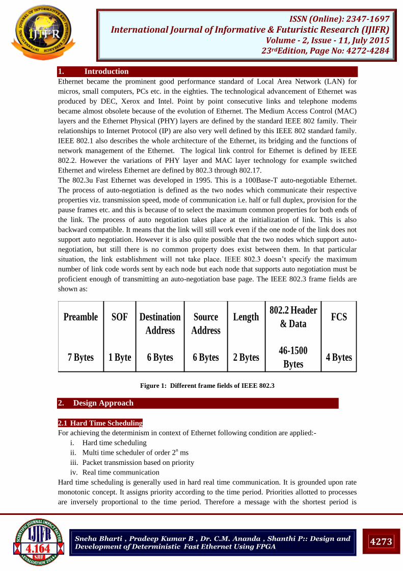
proficient enough of transmitting an auto-negotiation base page. The IEEE 802.3 frame fields are
shown as:
802.2 Header
& Data
46-1500
Bytes
Length
2 Bytes
Source
Address
6 Bytes
Destination
Address
6 Bytes
Preamble
7 Bytes
SOF
1 Byte
FCS
4 Bytes
Figure 1: Different frame fields of IEEE 802.3
2. Design Approach
2.1 Hard Time Scheduling
For achieving the determinism in context of Ethernet following condition are applied:-
i. Hard time scheduling
ii. Multi time scheduler of order 2n ms
iii. Packet transmission based on priority
iv. Real time communication
Hard time scheduling is generally used in hard real time communication. It is grounded upon rate
monotonic concept. It assigns priority according to the time period. Priorities allotted to processes
are inversely proportional to the time period. Therefore a message with the shortest period is
Page 3
4274
ISSN (Online): 2347-1697 International Journal of Informative & Futuristic Research (IJIFR)
Volume - 2, Issue - 11, July 2015 23rdEdition, Page No: 4272-4284
Sneha Bharti , Pradeep Kumar B , Dr. C.M. Ananda , Shanthi P:: Design and Development of Deterministic Fast Ethernet Using FPGA
allotted the highest priority. It executes a job with the shortest period first. It uses fixed priority
algorithm.
In this project Determinism in Ethernet was achieved by using Hard Time Scheduling. Hard Time
Scheduling is done by dividing the time in fixed interval and by assigning the fixed time period or
bandwidth to each Logical Link (LL). Allocation of bandwidth is done in between 1 ms to 128 ms.
The dimensions is determined by equation 1.
Bandwidth allocation = 2k ……...(1)
Where, k = an integer = 0 to 7.
The bandwidth allocation for each LL is allotted by the system integrator grounded on the
requirements of the application and is put in storage in the configuration tables for the end system
or switch.
Here base time is set as 1ms i.e. time is divided into 1ms time interval and goes up to 128 ms and it
repeats after every 128 ms. Here 8 packets namely T1, T2, T3, T4, T5, T6, T7, T8 are taken and
respective time periods 1ms, 2ms, 4ms, 8ms, 16ms, 32ms, 64ms, 128ms are assigned. T1 has
smallest period of 1ms which repeats after every 1ms and has highest priority. T2 repeats after
every 2ms and has second highest priority. Similarly, T3, T4, T5, T6, T7, T8 repeats after every
4ms, 8ms, 16ms, 32ms, 64ms, 128ms respectively.
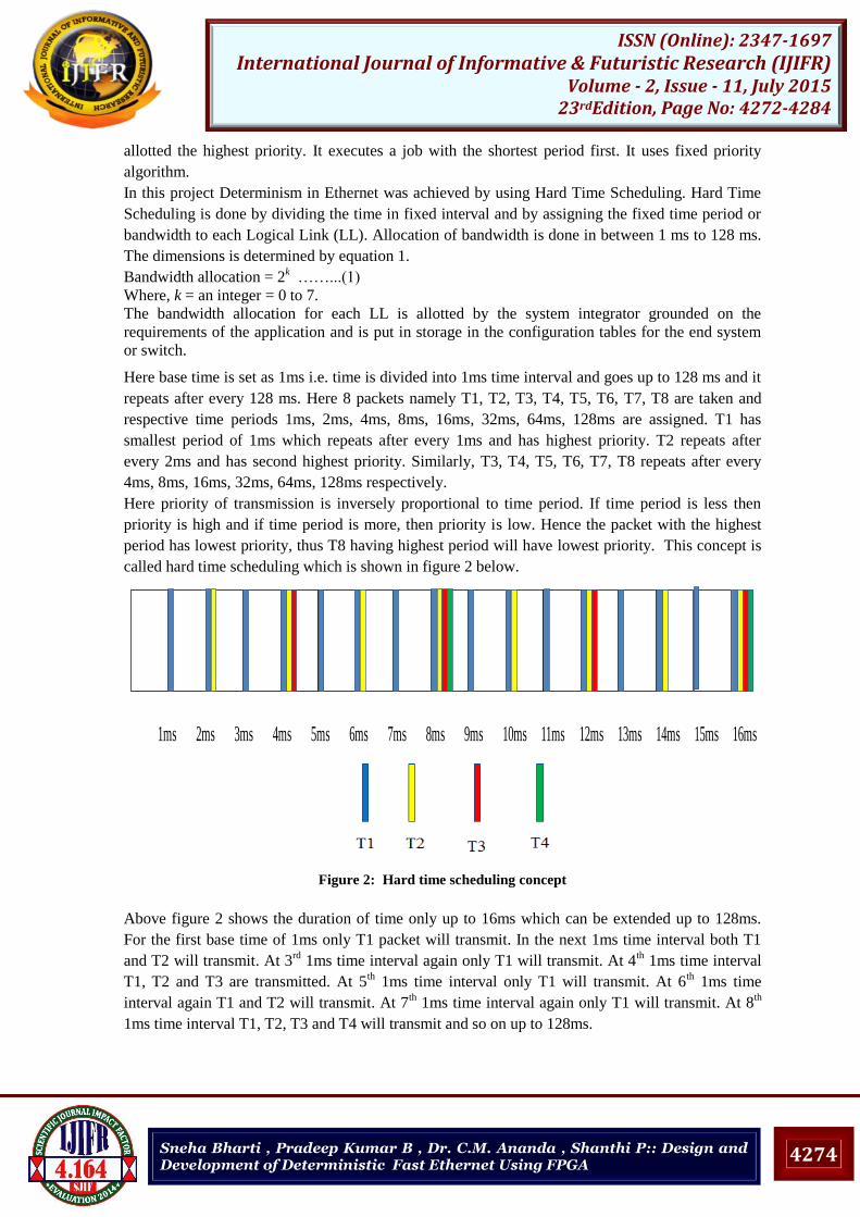
Here priority of transmission is inversely proportional to time period. If time period is less then
priority is high and if time period is more, then priority is low. Hence the packet with the highest
period has lowest priority, thus T8 having highest period will have lowest priority. This concept is
called hard time scheduling which is shown in figure 2 below.
1ms 2ms 3ms 4ms 5ms 6ms 7ms 8ms 9ms 10ms 11ms 12ms 13ms 14ms 15ms 16ms
Figure 2: Hard time scheduling concept
Above figure 2 shows the duration of time only up to 16ms which can be extended up to 128ms.
For the first base time of 1ms only T1 packet will transmit. In the next 1ms time interval both T1
and T2 will transmit. At 3rd
1ms time interval again only T1 will transmit. At 4th 1ms time interval
T1, T2 and T3 are transmitted. At 5th 1ms time interval only T1 will transmit. At 6
th 1ms time
interval again T1 and T2 will transmit. At 7th 1ms time interval again only T1 will transmit. At 8
th
1ms time interval T1, T2, T3 and T4 will transmit and so on up to 128ms.
Page 4
4275
ISSN (Online): 2347-1697 International Journal of Informative & Futuristic Research (IJIFR)
Volume - 2, Issue - 11, July 2015 23rdEdition, Page No: 4272-4284
Sneha Bharti , Pradeep Kumar B , Dr. C.M. Ananda , Shanthi P:: Design and Development of Deterministic Fast Ethernet Using FPGA
2.2 Frame structure
Preamble
7 Bytes
MAC
Destination
6 Bytes
SFD
1
Byte
MAC
Source
6 Bytes
UDP
Header
8 Bytes
IP
Header
20 Bytes
FCS
4
Bytes
IFG
12
Bytes
Padding
0-16
Bytes
Payload
1-18
Bytes
Type
IPv4
2 Bytes
Minimum Frame Length (64 Bytes)
Frame Begin Frame End
Preamble
7 Bytes
UDP
Header
8 Bytes
IP
Header
20 Bytes
IFG
12
Bytes
FCS
4
Bytes
Payload
1472 Bytes
SFD
1
Byte
MAC
Destination
6 Bytes
MAC
Source
6 Bytes
Type
IPv4
2 Bytes
Maximum Frame Length (1518 Bytes)
Frame EndFrame Begin
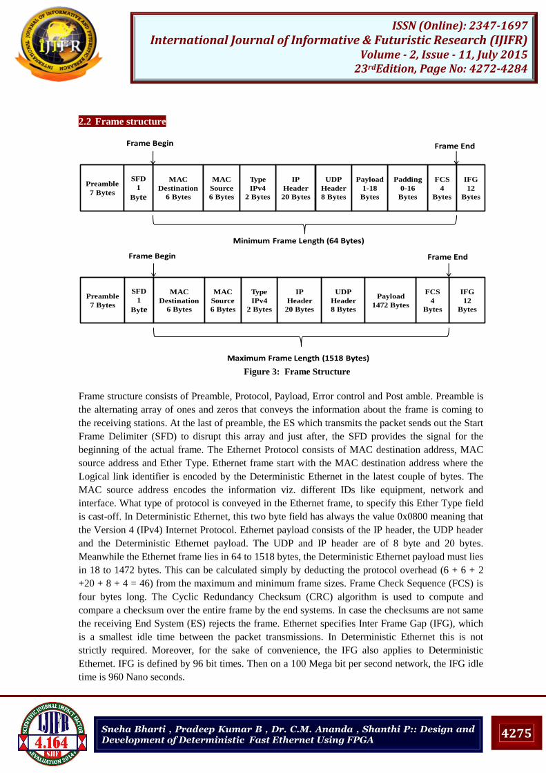
Figure 3: Frame Structure
Frame structure consists of Preamble, Protocol, Payload, Error control and Post amble. Preamble is
the alternating array of ones and zeros that conveys the information about the frame is coming to
the receiving stations. At the last of preamble, the ES which transmits the packet sends out the Start
Frame Delimiter (SFD) to disrupt this array and just after, the SFD provides the signal for the
beginning of the actual frame. The Ethernet Protocol consists of MAC destination address, MAC
source address and Ether Type. Ethernet frame start with the MAC destination address where the
Logical link identifier is encoded by the Deterministic Ethernet in the latest couple of bytes. The
MAC source address encodes the information viz. different IDs like equipment, network and
interface. What type of protocol is conveyed in the Ethernet frame, to specify this Ether Type field
is cast-off. In Deterministic Ethernet, this two byte field has always the value 0x0800 meaning that
the Version 4 (IPv4) Internet Protocol. Ethernet payload consists of the IP header, the UDP header
and the Deterministic Ethernet payload. The UDP and IP header are of 8 byte and 20 bytes.
Meanwhile the Ethernet frame lies in 64 to 1518 bytes, the Deterministic Ethernet payload must lies
in 18 to 1472 bytes. This can be calculated simply by deducting the protocol overhead (6 + 6 + 2
+20 + 8 + 4 = 46) from the maximum and minimum frame sizes. Frame Check Sequence (FCS) is
four bytes long. The Cyclic Redundancy Checksum (CRC) algorithm is used to compute and
compare a checksum over the entire frame by the end systems. In case the checksums are not same
the receiving End System (ES) rejects the frame. Ethernet specifies Inter Frame Gap (IFG), which
is a smallest idle time between the packet transmissions. In Deterministic Ethernet this is not
strictly required. Moreover, for the sake of convenience, the IFG also applies to Deterministic
Ethernet. IFG is defined by 96 bit times. Then on a 100 Mega bit per second network, the IFG idle
time is 960 Nano seconds.
Page 5
4276
ISSN (Online): 2347-1697 International Journal of Informative & Futuristic Research (IJIFR)
Volume - 2, Issue - 11, July 2015 23rdEdition, Page No: 4272-4284
Sneha Bharti , Pradeep Kumar B , Dr. C.M. Ananda , Shanthi P:: Design and Development of Deterministic Fast Ethernet Using FPGA
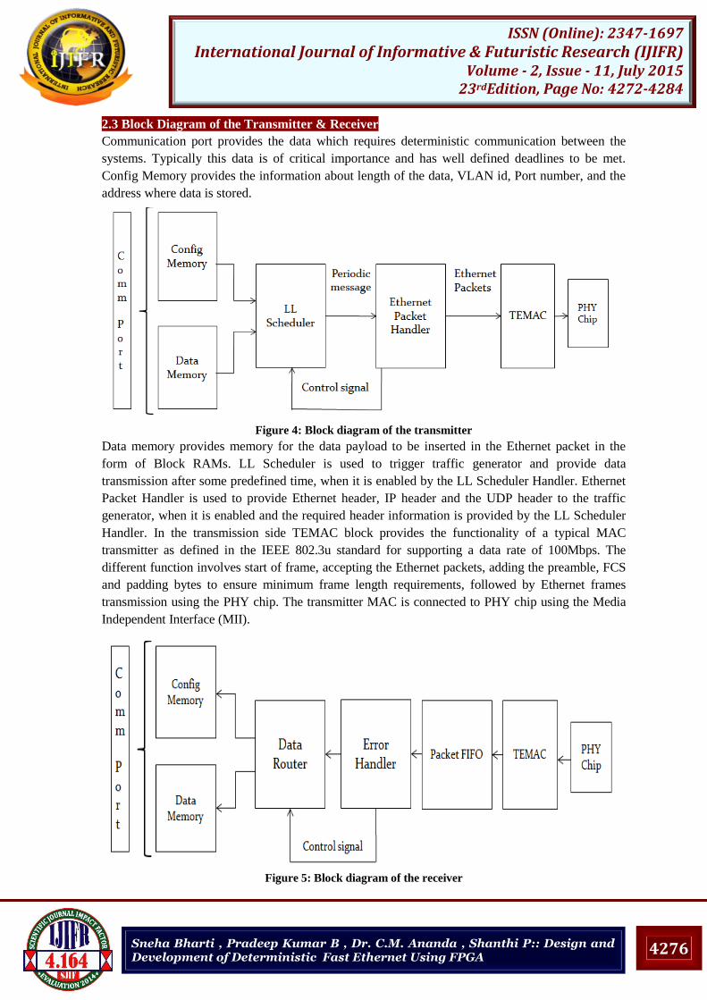
2.3 Block Diagram of the Transmitter & Receiver
Communication port provides the data which requires deterministic communication between the
systems. Typically this data is of critical importance and has well defined deadlines to be met.
Config Memory provides the information about length of the data, VLAN id, Port number, and the
address where data is stored.
Figure 4: Block diagram of the transmitter
Data memory provides memory for the data payload to be inserted in the Ethernet packet in the
form of Block RAMs. LL Scheduler is used to trigger traffic generator and provide data
transmission after some predefined time, when it is enabled by the LL Scheduler Handler. Ethernet
Packet Handler is used to provide Ethernet header, IP header and the UDP header to the traffic
generator, when it is enabled and the required header information is provided by the LL Scheduler
Handler. In the transmission side TEMAC block provides the functionality of a typical MAC
transmitter as defined in the IEEE 802.3u standard for supporting a data rate of 100Mbps. The
different function involves start of frame, accepting the Ethernet packets, adding the preamble, FCS
and padding bytes to ensure minimum frame length requirements, followed by Ethernet frames
transmission using the PHY chip. The transmitter MAC is connected to PHY chip using the Media
Independent Interface (MII).
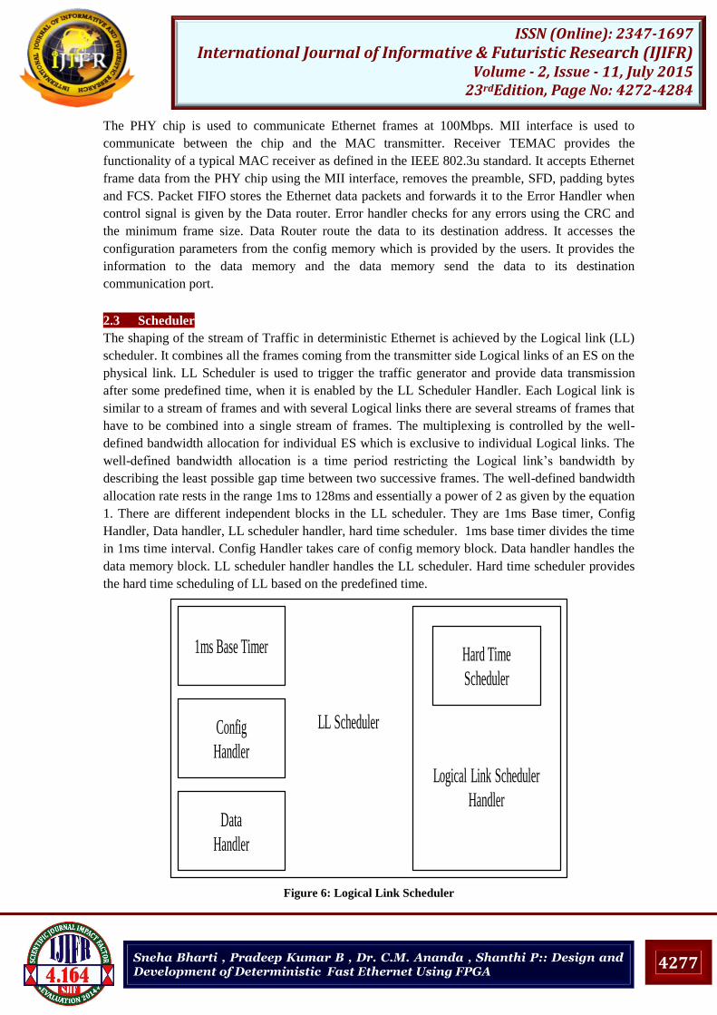
Figure 5: Block diagram of the receiver
Page 6
4277
ISSN (Online): 2347-1697 International Journal of Informative & Futuristic Research (IJIFR)
Volume - 2, Issue - 11, July 2015 23rdEdition, Page No: 4272-4284
Sneha Bharti , Pradeep Kumar B , Dr. C.M. Ananda , Shanthi P:: Design and Development of Deterministic Fast Ethernet Using FPGA
The PHY chip is used to communicate Ethernet frames at 100Mbps. MII interface is used to
communicate between the chip and the MAC transmitter. Receiver TEMAC provides the
functionality of a typical MAC receiver as defined in the IEEE 802.3u standard. It accepts Ethernet
frame data from the PHY chip using the MII interface, removes the preamble, SFD, padding bytes
and FCS. Packet FIFO stores the Ethernet data packets and forwards it to the Error Handler when
control signal is given by the Data router. Error handler checks for any errors using the CRC and
the minimum frame size. Data Router route the data to its destination address. It accesses the
configuration parameters from the config memory which is provided by the users. It provides the
information to the data memory and the data memory send the data to its destination
communication port.
2.3 Scheduler
The shaping of the stream of Traffic in deterministic Ethernet is achieved by the Logical link (LL)
scheduler. It combines all the frames coming from the transmitter side Logical links of an ES on the
physical link. LL Scheduler is used to trigger the traffic generator and provide data transmission
after some predefined time, when it is enabled by the LL Scheduler Handler. Each Logical link is
similar to a stream of frames and with several Logical links there are several streams of frames that
have to be combined into a single stream of frames. The multiplexing is controlled by the well-
defined bandwidth allocation for individual ES which is exclusive to individual Logical links. The
well-defined bandwidth allocation is a time period restricting the Logical link’s bandwidth by
describing the least possible gap time between two successive frames. The well-defined bandwidth
allocation rate rests in the range 1ms to 128ms and essentially a power of 2 as given by the equation
1. There are different independent blocks in the LL scheduler. They are 1ms Base timer, Config
Handler, Data handler, LL scheduler handler, hard time scheduler. 1ms base timer divides the time
in 1ms time interval. Config Handler takes care of config memory block. Data handler handles the
data memory block. LL scheduler handler handles the LL scheduler. Hard time scheduler provides
the hard time scheduling of LL based on the predefined time.
1ms Base Timer
Logical Link Scheduler
HandlerData
Handler
Config
Handler
Hard Time
Scheduler
LL Scheduler
Figure 6: Logical Link Scheduler
Page 7
4278
ISSN (Online): 2347-1697 International Journal of Informative & Futuristic Research (IJIFR)
Volume - 2, Issue - 11, July 2015 23rdEdition, Page No: 4272-4284
Sneha Bharti , Pradeep Kumar B , Dr. C.M. Ananda , Shanthi P:: Design and Development of Deterministic Fast Ethernet Using FPGA
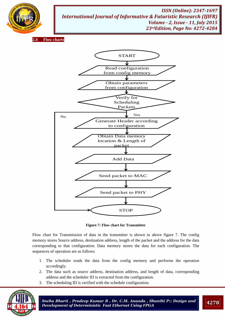
2.4 Flow charts
START
Generate Header according
to configuration
Verify for
Scheduling
Packets
YesNo
Obtain Data memory
location & Length of
packet
Add Data
Send packet to MAC
Send packet to PHY
STOP
Read configuration
from config memory
Obtain parameters
from configuration
Figure 7: Flow chart for Transmitter
Flow chart for Transmission of data in the transmitter is shown in above figure 7. The config
memory stores Source address, destination address, length of the packet and the address for the data
corresponding to that configuration. Data memory stores the data for each configuration. The
sequences of operation are as follows
1. The scheduler reads the data from the config memory and performs the operation
accordingly.
2. The data such as source address, destination address, and length of data, corresponding
address and the scheduler ID is extracted from the configuration.
3. The scheduling ID is verified with the schedule configuration.
Page 8
4279
ISSN (Online): 2347-1697 International Journal of Informative & Futuristic Research (IJIFR)
Volume - 2, Issue - 11, July 2015 23rdEdition, Page No: 4272-4284
Sneha Bharti , Pradeep Kumar B , Dr. C.M. Ananda , Shanthi P:: Design and Development of Deterministic Fast Ethernet Using FPGA
4. If the ID should be scheduled the trigger for the packet generation is generated. Else repeat
the step from 1 to 4.
5. The header is generated based on the configuration and the corresponding data from the
data memory is extracted.
6. The final packet is generated with MAC, IP, UDP and data is sent to TEMAC.
7. The final packet along with preamble and CRC is sent to Ethernet PHY.
START
Check Integrity
Receive Packet from the
PHY
Send Packet to MAC &
Remove Overheads
Store Packet in FIFO
YesNo
Send packet to its destination
STOP
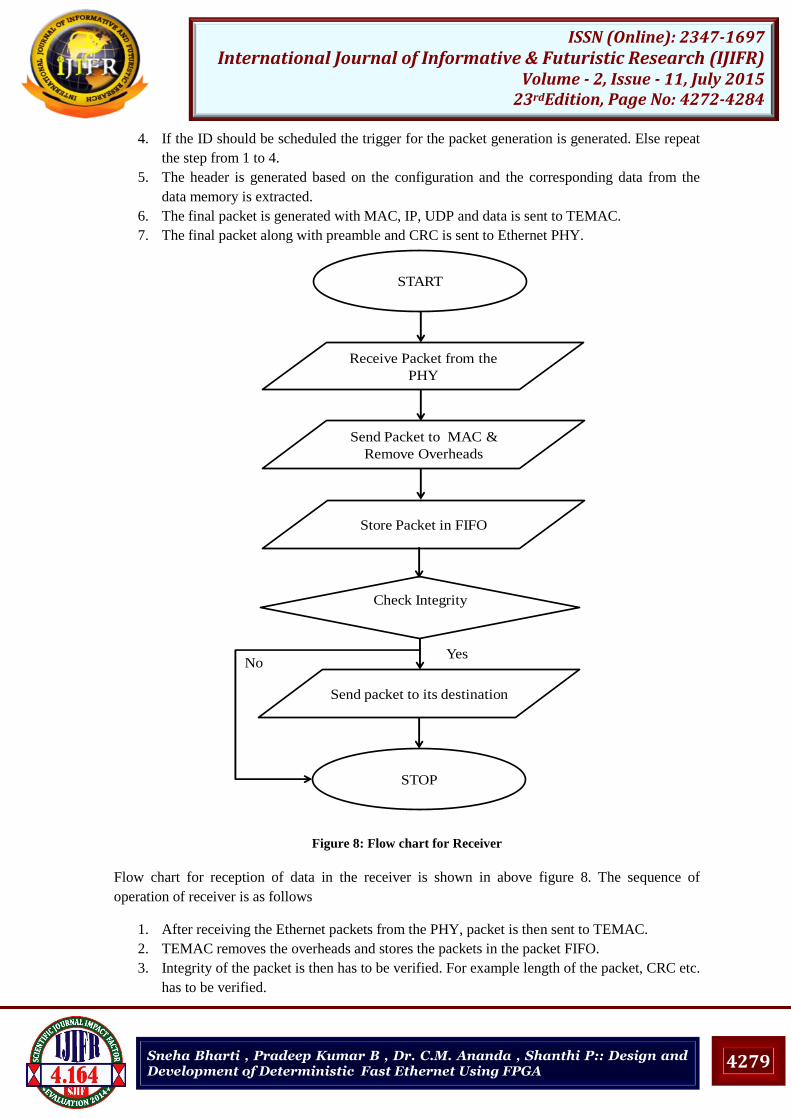
Figure 8: Flow chart for Receiver
Flow chart for reception of data in the receiver is shown in above figure 8. The sequence of
operation of receiver is as follows
1. After receiving the Ethernet packets from the PHY, packet is then sent to TEMAC.
2. TEMAC removes the overheads and stores the packets in the packet FIFO.
3. Integrity of the packet is then has to be verified. For example length of the packet, CRC etc.
has to be verified.
Page 9
4280
ISSN (Online): 2347-1697 International Journal of Informative & Futuristic Research (IJIFR)
Volume - 2, Issue - 11, July 2015 23rdEdition, Page No: 4272-4284
Sneha Bharti , Pradeep Kumar B , Dr. C.M. Ananda , Shanthi P:: Design and Development of Deterministic Fast Ethernet Using FPGA
4. If yes then send packets to its destination address according to the user configuration which
is provided by the configuration memory and stop the reception process.
5. If the CRC does not match with the received CRC, which is sent by the transmitter then the
corresponding packet is discarded and the process is stopped.
3. Test Results And Discussions
This section describes the simulation and implementation results of the design. Simulation is done
by using the ISIM (P.68d) which is a tool in the ISE. Implementation of the design is done by using
Wireshark, which is an open source packet analyser.
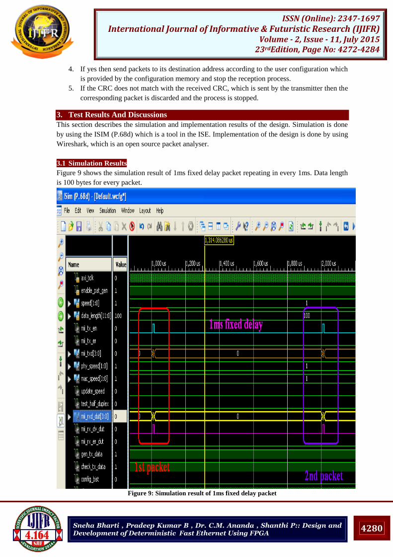
3.1 Simulation Results
Figure 9 shows the simulation result of 1ms fixed delay packet repeating in every 1ms. Data length
is 100 bytes for every packet.
Figure 9: Simulation result of 1ms fixed delay packet
Page 10
4281
ISSN (Online): 2347-1697 International Journal of Informative & Futuristic Research (IJIFR)
Volume - 2, Issue - 11, July 2015 23rdEdition, Page No: 4272-4284
Sneha Bharti , Pradeep Kumar B , Dr. C.M. Ananda , Shanthi P:: Design and Development of Deterministic Fast Ethernet Using FPGA
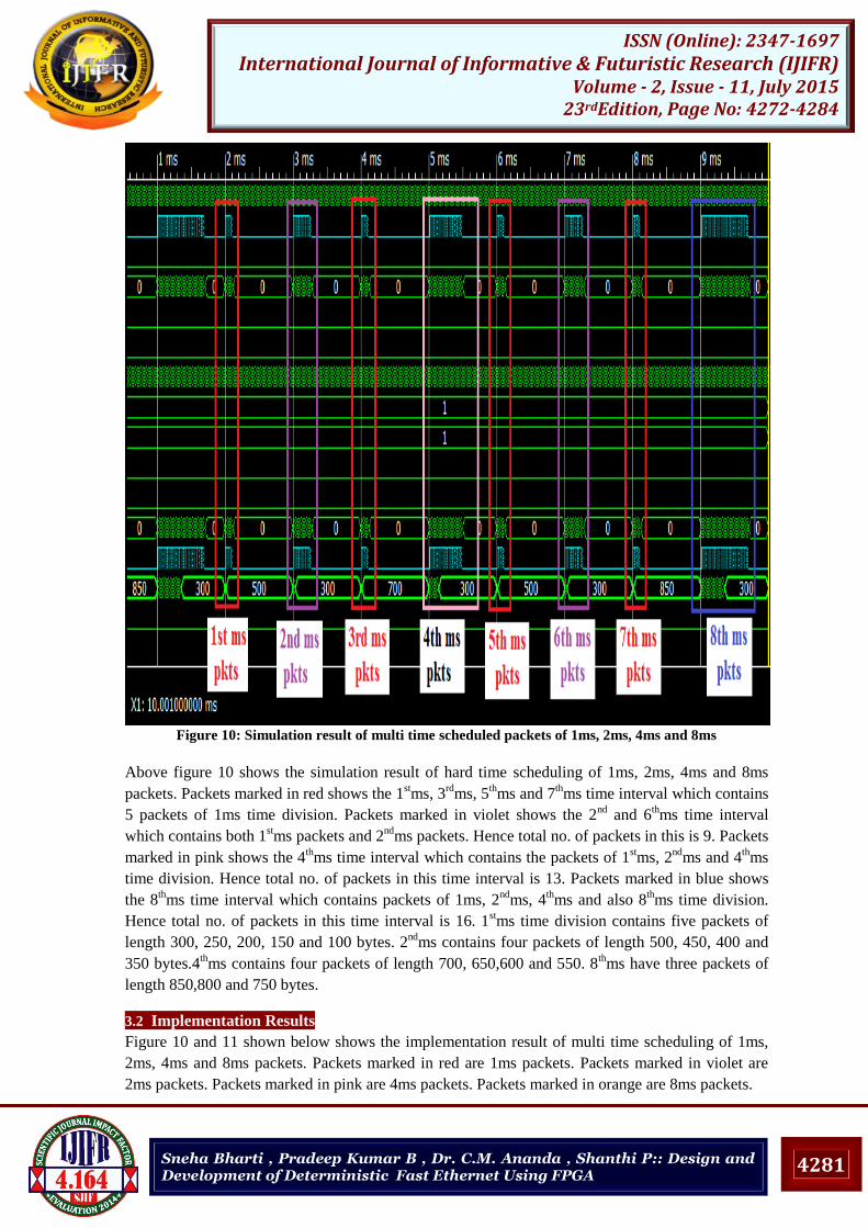
Figure 10: Simulation result of multi time scheduled packets of 1ms, 2ms, 4ms and 8ms
Above figure 10 shows the simulation result of hard time scheduling of 1ms, 2ms, 4ms and 8ms
packets. Packets marked in red shows the 1stms, 3
rdms, 5
thms and 7
thms time interval which contains
5 packets of 1ms time division. Packets marked in violet shows the 2nd
and 6thms time interval
which contains both 1stms packets and 2
ndms packets. Hence total no. of packets in this is 9. Packets
marked in pink shows the 4thms time interval which contains the packets of 1
stms, 2
ndms and 4
thms
time division. Hence total no. of packets in this time interval is 13. Packets marked in blue shows
the 8thms time interval which contains packets of 1ms, 2
ndms, 4
thms and also 8
thms time division.
Hence total no. of packets in this time interval is 16. 1stms time division contains five packets of
length 300, 250, 200, 150 and 100 bytes. 2nd
ms contains four packets of length 500, 450, 400 and
350 bytes.4thms contains four packets of length 700, 650,600 and 550. 8
thms have three packets of
length 850,800 and 750 bytes.
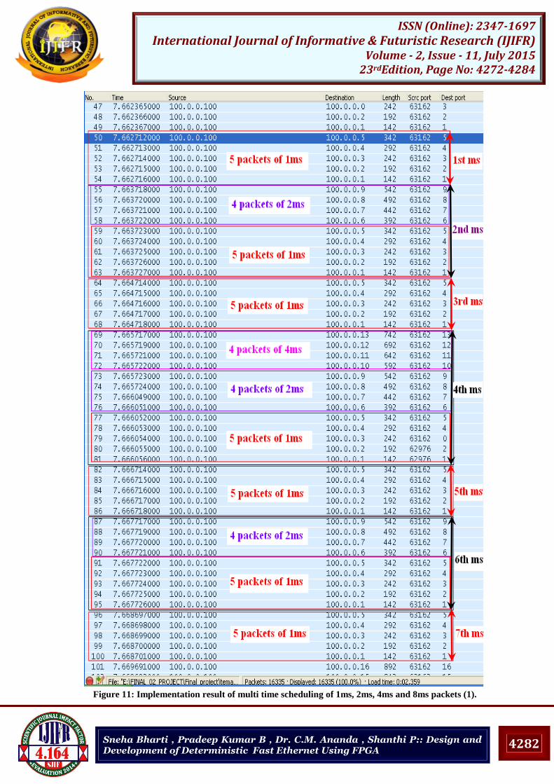
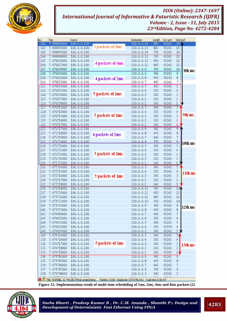
3.2 Implementation Results
Figure 10 and 11 shown below shows the implementation result of multi time scheduling of 1ms,
2ms, 4ms and 8ms packets. Packets marked in red are 1ms packets. Packets marked in violet are
2ms packets. Packets marked in pink are 4ms packets. Packets marked in orange are 8ms packets.
Page 11
4282
ISSN (Online): 2347-1697 International Journal of Informative & Futuristic Research (IJIFR)
Volume - 2, Issue - 11, July 2015 23rdEdition, Page No: 4272-4284
Sneha Bharti , Pradeep Kumar B , Dr. C.M. Ananda , Shanthi P:: Design and Development of Deterministic Fast Ethernet Using FPGA
Figure 11: Implementation result of multi time scheduling of 1ms, 2ms, 4ms and 8ms packets (1).
Page 12
4283
ISSN (Online): 2347-1697 International Journal of Informative & Futuristic Research (IJIFR)
Volume - 2, Issue - 11, July 2015 23rdEdition, Page No: 4272-4284
Sneha Bharti , Pradeep Kumar B , Dr. C.M. Ananda , Shanthi P:: Design and Development of Deterministic Fast Ethernet Using FPGA
Figure 12: Implementation result of multi time scheduling of 1ms, 2ms, 4ms and 8ms packets (2)
Page 13
4284
ISSN (Online): 2347-1697 International Journal of Informative & Futuristic Research (IJIFR)
Volume - 2, Issue - 11, July 2015 23rdEdition, Page No: 4272-4284
Sneha Bharti , Pradeep Kumar B , Dr. C.M. Ananda , Shanthi P:: Design and Development of Deterministic Fast Ethernet Using FPGA
4. Conclusion
It can be seen from the test results that implementation for the multi-scheduler based Deterministic
Ethernet has been successfully simulated, implemented and tested. This new technique can be
adopted for many real time applications specifically for packet transmission in hard real time
communications like avionics and marine communication. A complete Ethernet packet with the
MAC header, IP header, UDP header and the data payload has been created using Xilinx tools and
the results have been simulated and implemented on FPGA, for scheduling the Ethernet packets at a
predetermined time interval for real time deterministic communication.
References [1] C. Venkatramani and T. S. Chiueh, “Supporting real-time traffic on Ethernet”, Proc. IEEE RTSS’94, pp.
282-286, Dec. 1994
[2] D. W. Pritty, J. R. Malone, S. K. Banerjee and N. L. Lawrie, “A real-time upgrade for Ethernet based
factory networking”, Proc. IECON, pp. 1631-1637, 1995.
[3] Malcolm, N. and Zhao, W., “The timed token protocol for real-time communication”, Proc. IEEE
Computers, 27(1): 35 41, 1994.
[4] Gonzalo Carvajal, Chun Wah Wu, and Sebastian Fischmeister, “Evaluation of Communication
Architectures for Switched Real-Time Ethernet”, IEEE transactions on computers, Vol. 63, No. 1,
January 2014,pp: 218-229.
[5] Jozsef Suto and Stefan Oniga, “FPGA implemented reduced Ethernet MAC”, CogInfoCom 2013, 4th
IEEE International Conference on Cognitive Info-communications, December 2–5, 2013 , Budapest,
Hungary, pp: 29-32.
[6] S. Ouni and F. Kamoun, “Hard and soft real time message scheduling on Ethernet networks”, Proc. 2002
IEEE SMC, vol. 6, October 6-9, 2002, Hammamet, Tunisia.
[7] Krishna C.M. and Shin K.G, “Real-Time Systems”, Tata McGraw-Hill, 1997.
[8] ARINC 664, Aircraft Data Network Part 7 Avionics Full-Duplex Switched Ethernet Network. Annapolis,
Maryland, Aeronautical Radio Inc., 2009.