INTERNATIONAL JOURNAL OF SCIENCE AND P.O. Box 38, Plainfield, Indiana 46168, U.S.A. Editor-in-Chief Professor S. lmtlaz Ahmad, Eastern Michigan University Associate Editors Artificial Intelligence Professor Robert G. Reynolds, Wayne State University Database Systems Professor William Irvin Grosky, Wayne State Digital Signal Processing Professor Mustafa M. Fahmy, Queen's University .. , Diffusion in liquids & Polymeric Membranes Professor Abdul-Fattah A. Asfour, University of W indSor Electromag. Compatib. Assess. of Dev. Professor Abdul Haq Qureshi, Cleveland State University Engineering Hydraulics Professor John Alexander McCorquodale, University of Enhanced Oil Recovery Professor Francis Andrew Dullien, University of w alt erlcV\'11 Housing for Developing Countries Professor Guizar S. Haider, Carleton University Infonnation Technology Professor David C. Coll, Carleton University Laser and Applications Professor Walter W. Duley, York: Univer.sity Plasma Physics Professor Mazhar Hasan, Northern Illinois University- Production Systems Professor Salah E. Elmagbraby, North Carolina State Reliability Engineering Professor Elsayed A. Elsayed, Rutgers University Robotics Profe660r Paul G. Ra nky, The University of Michigan Systems and Controls Professor Nasiruddin Ahmed, University of Ottawa Viruses and Human Health Professor Syed Abdus Sattar, University of Ottawa VLSI Architecture for Signal Processing Professor M. Ahmed, Boston University X and Gama Ray Sources Professor Carl B. Collins, University of Texas at Dallas Executive Editor Dr. Iqbal J. Unus, Foundation for International Development INTERNATIONAL JOURNAL OF SCIENCE AND TECHNOLOGY- (ISSN-0891-5083) is published by FID, The Foundation for International Development. FID headquarters: P Plainfield, IN. 46168 USA. (31 7) 839 -8157. Annual subaiption: Individual US $20.00, Student US $10. 00 , $35.00. Overseas subscribers pay additional dues for postage. Please send subscription request and address Headquarters. Single copi es are charged US $10.00. Please send all orders to FID Headquarters. Ra tes for advertising in the Journal are available on request. Copright 1 987 by tbe Foundation for International Development. Copying and abstracting for noncommercial permitted provided that credit is given to the original source. Postmaster: Please send undelivered cop i es and address changes to FlD Headquarters, P.O.Box 38, USA Enquires regarding s ubscriptions, purchase orders and advertising should be directed to: Khadija Khuwayled Office M anager Foundation for International Development P.O.Box 38, Plainfield, IN. 46168 USA Phone: (317) 839-8157 *Tel ex: 650 255 4110
Transcript
INTERNATIONAL JOURNAL OF SCIENCE AND POBox 38 Plainfield Indiana 46168 USA
Editor-in-Chief Professor S lmtlaz Ahmad Eastern Michigan University
Associate Editors
Artificial Intelligence Professor Robert G Reynolds Wayne State University Database Systems Professor William Irvin Grosky Wayne State Universitv~middot)Jf
Digital Signal Processing Professor Mustafa M Fahmy Queens University Diffusion in liquids amp Polymeric Membranes Professor Abdul-Fattah A Asfour University of WindSor
Electromag Compatib Assess of Dev Professor Abdul Haq Qureshi Cleveland State University Engineering Hydraulics Professor John Alexander McCorquodale University of Enhanced Oil Recovery Professor Francis Andrew Dullien University of w alterlcV11
Housing for Developing Countries Professor Guizar S Haider Carleton University Infonnation Technology Professor David C Coll Carleton University
Laser and Applications Professor Walter W Duley York University Plasma Physics Professor Mazhar Hasan Northern Illinois Universityshy
Production Systems Professor Salah E Elmagbraby North Carolina State Reliability Engineering Professor Elsayed A Elsayed Rutgers University
Robotics Profe660r Paul G Ranky The University of Michigan Systems and Controls Professor Nasiruddin Ahmed University of Ottawa
Viruses and Human Health Professor Syed Abdus Sattar University of Ottawa VLSI Architecture for Signal Processing Professor H~n M Ahmed Boston University
X and Gama Ray Sources Professor Carl B Collins Universi ty of Texas at Dallas
Executive Editor Dr Iqbal J Unus Foundation for International Development
INTERNATIONAL JOURNAL OF SCIENCE AND TECHNOLOGYshy(ISSN-0891-5083) is published by FID The Foundation for International Development FID headquarters P Plainfield IN 46168 USA (317) 839-8157 Annual subaiption Individual US $2000 Student US $1000 Instillip~ $3500 Overseas subscribers pay additional dues for postage Please send subscription request and address chwiampt~ Headquarters Single copies are charged US $1000 Please send all orders to FID Headquarters
Rates for advertising in the Journal are available on request
Copright 1987 by tbe Foundation for International Development Copying and abstracting for noncommercial permitted provided that credit is given to the original source
Postmaster Please send undelivered copies and address changes to FlD Headquarters POBox 38 USA
Enquires regarding subscriptions purchase orders and advertising should be directed to
Khadija Khuwayled Office Manager
Foundation for International Development POBox 38 Plainfield IN 46168 USA
Phone (317) 839-8157 Telex 650 255 4110
BODNER-PARTOM VISCOPLASTIC CONSTITUTIVE MODEL AND THE NON
I NEAR FINITE ELEMENT ANALYSIS OF A STRESS CONCENTRATION AT
IGH TEMPERATURE F A Kolkailah Professor of Aeronautical Engineering California Polytechnic State University Sao Luis Obispo CA 93407
A J McPbate Professor of Mechanical Engineering Louisiana State University Baton Rouge lA 70803
middot ~ The design and analysis ofstructural components tc operate at elevated temperature and severe stress levels such as a low-cycle fatigue-limited jet engine disk require an accurate prediction ofthe nonlinear stress-strain
response encountered during the cyclic loading condiJions Nonlinear analysis ofsuch components is normally carried out by a finite element code making use ofconstitutive theories in which the material response is separated into the two important groups ofphenomena known as rate dependent creep and rate independent plasticity A number ofviscoplastic constitutive theories in which creep and plasticity effects are combined _into a unified plastic strain model have recendy been proposed and are still undergoing active deveibpment In this paper an elastic-plastic finite element model incorporating the Bodner-Parligtm model ofnonlinear time dependent material behavior is presented The parameters in the constitutive model are numerically extracted by a least-square fit to experimental data obtained from uniaxial stress-strain and creep tests at 65ifC The finite element model ofa double notched specimen is employe_d to determine the elastic-plastic strain and comparison is
made to experimental data
e
The constitutive model parameters evaluated in this paper are found IC be in good agreement with those obtained by other investigators However this numerical technique tends tc give bener agreement with the respo11Se curves than does the graphical methods used by the other investigators The model calculated ef4$1jc-plastic strain agreed well with the experimental
Inconel 718 is a high temperature superalloy of Rene 95 at 1200F Stouffer [2] used the state developed for low-cycle fatigue limited components variable constitutive equations of Bodner and Partom operating at high temperature and severe stress in a to calculate the mechanical response of IN 100 at hostile environment To properly use the alloy it is 1350F Hennerichs [3] estimated the materials necessar y to know and be able to properly constants in IN 100 by using Bodner and Partom characterize its time dependent elastic-plastic constitutive equations Milly [ 4 ] represented the properties A number of viscoplastic constitutive experimental data for Inconel 718 at 1200F from theores combining creep and plasticity effects into a which the material constants were determined by tbe unified plastic strain model have recently been method given by Stouffer [2] Milly applied the proposed and are undergoing active development Bodner constitutive equations and compared the One of these theories used in this study is the theory and experimental data and concluded the COnstitutive theory of Bodner and Partom [1] overall behavior was good
Bodner [1] utilized the constitutive equations of There are a large number of finite elements in use Bodner and Partom to represent the inelastic behavior today for both plane stress and plane strain analysis
Inti J Science and Technology 5 Volume 2 Number 2 F aii1 9891Winter 1990
for example the coostaot strain triangular elements hybrid elements and higher order isoparametric elements For linear elasticity the mathematical development of these elements is simple Since the coostant strain triangular elements have advantages of being simple and economical they were selected to be employed in this study The e~tic-plastic code was used in the numerical determination of Lbe elastic stress concentration (Kc) for benchmark notched specimen under constant tensile load and for the elastic-plastic response of that specimen for cyclic loading
Domas Sharpe Ward and Yau [7] in the analytical task of their study used the finite element method and calculated stress and strain at element centroids for good estimation of tbe elastic stress concentration factor (Kc)
Hennerichs (3] incorporated the Bodner constitutive model into a constant-strain triangular elements model to analyze creep aack growth in a nickel alloy at 1350F
The Constitutive Theory of Bodner and Par1om The constitutive theory of Bodner a(l) is based ooshy
the assumption of small strain and that the total strain rate pound t(t) is separable into elastic (reversible) pound c(t) and plastic (irreversible) ~ P(t) components both non-zero for all loadingunloading conditions
f I (t) bull f ~ (t) + poundP (t) (1) where
e P(t) shy a(t)~ (2)
For the plastic strain rate ep(t) the specific representation used by Bodner and Partom is given by
eP(t) bull _1_ pound1 Do ex [ (Z(t) ) 211 (n+l)) (3)V3 o(t) p 2 o(t) n
where o (t)=The current value of the stress
0 0 =a constant representing the limiting value of the plastic strain rate in shear Generally it is taken at 104 sec- except for conditions of very bigb rates of strain
n =a constant related t vi soosity of the dislocation motion It contro~ the strain rate sensitivity
Z(t) =the plastic state variable measure of the overall res~ce to plastic flow that i1 hardness
The evolution equation ie history dependence of the plastic state variable is generally sought in the form of a differential equation for the hardening rate Z that depends on stress temperature and hardness Z A more specific representation is based on the concept that only the plastic rate of working wP and
current hardness Z control the rate of hardening The complete expression for Z can be written as [11 middot Z = Zt- (Zt - Zo) exp (-mWp) or (Z - Zt) = (Zt - Zo) exp(-mWp)
where m =a material constant controlling the rate of woeki
hardening 1bull
Zt =the saturation value of Z for large Wp ie_ il is J the maximum value of Z taken to be constant middot ~ =the initial value of Z corresponding to tb~~
reference state from which Wp is measured Bounds are (0 s Zo s Z1)middot I
Wp is defined by the differential equation 1 middot~ bulltmiddotmiddot
P bullp z~coveryW - oe- + ____
m(Z1 - Z) (5) l ~
to give ti ~ middot p r middotp tlrecovery
W bull J o amp dt + J(Z _ Z) dt 1
where
z Zmiddot 1Z ~laquoOW) bull -AZt (- )
1
Therefore the complete differential expression or~ is written as
Z bull m(Z1- Z) WP -AZ1 (-- Z)Z1
where J~ t I bull
A =the coefficient controlling the rate of hardeJ t~ 1 recovery bull bull i
r =the exponent controlling lbe rate of bardenin - middot ~ recovery l
Z1 =the state variable value corresponding to the complete non-work hardened condition a functioo of temperature
In (8) the second term is hardening recovery negligible during brief load histories but for loog lime response such as aeep the second term is necessary middot During a teosile test fast compared to aeep equali~ (8) reduces to the first term only For a tensile test equation (8) becomes
z bull m(Z1- Z) WP (9) In lbis case wP is determined by only
Irtf J Science and Technology 6
In order to determine the viscoplastic material constants in these constitutive equations the constants are considered to be in two groups creep response and short time response The short time response constants are Do n m Zo and Z1 and they are determined based on stress-strain test data The creep
middot response constants are Zt r A and they are determined based on data from at least two creep tests at two different stress levels Step-by-step theoretical
-~ evaluation of tbe material paramete~ was developed _ by Bodner (1] for Rene 95 and by Stouffer (2] for In
100 Also Stouffer and Bodner [5] studied the relationship between theory and experiment for the state variable constitutive equation Therefore to
middot complete the study of the constitutive equations a numerical evaluation of the material paramete~ was
middot undertaken
Numerical Evaluation or the Material Parameters middot A numerical study of nonlinear time dependent material was considered where the material variables are numerically calculated using a direct curve fitting technique
In general the Bodner material parameters are dependent on temperature but by performing the
middot material characterization tests (stress-strain and creep) at the same t~mperature that the Bodner model will be applied the temperature dependence is suppressed
To determine the Bodner variables (n Zo Zb m A r Zt and Do) numerically we consider the measured
- and the simulation of the plastic strain For the
evaluation of simulated poundP (t) the total strain rate is considered the sum of elastic and plastic strain rates
(1)
where
pounde(t) bull a(t)IE (2)
Therefore we can rewrite equation (1) in the form
poundP(t) - pound1(t) - Ot)I E (11)
where a (t) is extracted from the data
For the evaluation of theoretical poundP we consider the flow law
~ poundP(t)- JS (12)
where S is the deviatoric stress and A is a scalar function of the state of the materiaL
k =k(X) where
lt X gt =ltnZoZtmArZiDogt Equation (12) becomes
poundP(t) bull A(X) S(t)
and
E 1(t) - E
1(0) +Ipound p(tdt+ if
where pound 1(0) is taken from tbe data
Now let
Qbull L W(t) (eodel - pound~a)2 Data
where w(t) is a positive weight function and
( E ~odel - e ~) is the time domain strain error Q
was minimized in a computerized numerical scheme by varying values of the material coefficients In this analysis a Runge Kutta (fourth order) algorithm was employed for the numerical time integration of the Bodner equations in the following system
trP Z -Z rZbullm(Zt-Z) w -AZ1 t-z-) (8)
(10)
(12)
I j
z2P 2 1
D2
- D exp [-(-) (n+- )] (17) I~ o 312 n n
rwhere J2 is the second stress invariant and equation middot
(17) is from reference (1]
Using a variant of Pbwells (6] search algorithm ~coupled with the integral square error function the specific material variables for the Bodner model were determined to best fit the tensile and creep data Tbe~men~JDa~
In the experimental part of this research a group of tensile and creep tests were performed for lncooel 718 at 650degC The Bodner model coupled with this set of data was employed to determine the material variables of Incooel 718 to best fit the data
To belp eliminate inconsistencies in data the same specimen geometry was used for all tests A drawing of the button-head specimen used in this study is presented in figure 1
All experiments were performed in an electrohydraulic testing machine equipped with a
(13)
(14)
(15)
middotbullt J
(16)
Inti J Science and Technology 7 Volume 2 Number 2 Faii1989Winter 1990 I
special high-temperature furnace Special attention was given to the alignment of the specimen to minimize the eccentricity of the load and to obtain a uniform temperature profile in the test section The machine was run under strain control The data (stress strain lime) was obtained by using the Interferometric StrainDisplacement Gage (ISDG) technique developed and conducted by W N Sharpe
The Elastic-Plastic Finite Element Model The locally written finite-element program
generates constant strain triangular elements with very fine elements in the root of the notch The 2-D program was formulated for plane stress calculaHon and uses the plastic force method to enforce plastic stra in Only one quarter of the specimen was modelled due to symmetry and an automatic mesh generation algorithm permitted easy variation of the total mesh size It was thus possible to easily select the proper balance between mesh fineness and computation time A mesh of 176 nodes and 300 elements was eventually chosen figure 2
Results and Conclusions Uniaxial tensile tests were run at strain rates of 16
X 103 067 X 104 10 X 10middot5 11 X 10-6 and 33 X
wmiddot1 sec middot l 1vo creep tests were run at 758 and 862 MPa The data for each test was smoothed and approximately 20 data points used for each test in the fitting procedure The modulus of elasticity was considered as a parameter increasing the number of constants to be determined to nine Different starling values were tried producing slightly different values of constants though no appreciable difference in the agreement with individual curves A unique set of constants was not already determined to cover the complete data base
The flnal parameters determined are listed in Table 1 where the values from Milly [4] are also listed Figures 3 4 5 and 6 show the response curves from the model and the experimental data Agreement in flgures 3 and 4 are reasonable except for the fastest tensile test Figures 5 and 6 are not good but the agreement is considerably better than other comparisons [24] The model modulus of elasticity 172 x 103
MPa is high for this material at this te~perature Other determinaHons place it at 155 x 10 MPa[3) As can be obsaved from figures 3 and 4 the modulus for the experimental data is higher still at the faster rates Nevertheless the Bodner Model describes the results fairly well given tbe wide range of strain rates and the fact that 650deg is near a phase transition
This numerical scheme for identifying the Bodner parameters is straightforward and lends to give better agreement with the response curves than graphical methods The Bodner model does reasonably wen io describing stress-strain curves covering a wide range
4of strain-rates (almost 10 in these experiments) and creep curves Actually it is a stiff requirement to ast a model to cover such a wide variety of material response The eight parameters of the Bodner model give it the requisite range but a unique set of parameters was not obtained In general one can make the following conclusions
( 1)A numerical evaluation of the material variables can be made by using Bodner constitutive theory through a numerical simulation of the tensile and creep response with reasonable curve fitting to tho experimental response
(2)Bodner Constitutive theory is sensitive to the variability of the experimental data Since the stress a is the driving force in the constitutive model special attention should be given to the time data for a smooth (a -t) curve
(3)As in Reference [1] Bodner constitutive theory may need further work to decide on improvements which can be made to include effects that would lead to tertiary creep in the representations
(4)From the fact that the calculated values for some of the variables are different for the same value of fltting error (and they should not be) and from the fact that for some runs 4 and Z1 have the same value (and they should not) it can be recognized that the material variables in Bodners Constitutive model are not well defined More specifically they are not universal which may address that 650deg is near a transition temperature for this material
The finite-element model does a good job of evaluating the theoretical elastic stress concentration K and predicting the notch behavior under low cycle loading at high loads The response at the notch is very complicated given the finite plastic strains generated Figure 7 shows the experimental data aod finite-element prediction for the comparison of measured notch strain with that predicted by the finite element durinsect the first cycle of continuous cyclic loading at 650 C
For further application using the Bodner-Partom state variable material model and model parameters developed from uniaxial test data creep aadt growth in Inconel 718 was analyzed by using the coostanl strain finite element for compact tension specimen (8]
Crack growth behavior identified solely from crack opening displacement measurements made on pre-cracked specimens was analyzed by examining various parameters around the models crack tip 1be
Inti J Science and Technology 8 Volume 2 Number 2 Fall1989tWinter 1990
J-integral was applied and used to predict crack loading and the aack propagation material state was growth initiation Promising results were obtained not the same as the initial state of the uniaxial test
In reviewing the response figure 8 one must keep specimen in mind the initial material uniaxial data The cracked
specimens were actually pre-cracked by fatigue
REFERENCES tBodner S R and Partom Y Constitutive
Equarion for Eastic-Viscoplastic Strain Hardening Materials Journal of Applied Mechanics Trans ASME ~ 385-389 1975
2Stouffer D C A Constitutive Representation for IN-100 Air Force Wright Aeronautical Laboratories AFWAL-TR-81-4039 30 pgs 1981
bull 3Hinnerichs T Nicholas T and Pulayatlo A A Hybrid Experimental-Numerical Procedure for Determining Creep Craclc Growth Rates Engineering Fracture Mechanics 16 265-277 1982
4Milly T M and Allen D H A Comparative Study of Nonlioear Rate-Dependent Medlanical Constitutive Theories for Crystalline Solids at Elevated Temperatures Report AP1-E-5-82-5 Virginia Polytechnic Institute and State University March 1982
5Stouffer D C and Bodner S R A Relationship Between Theory and Experiment for a State Variable Constitutive Equatioo AF WAL-TR-80-4194 Wright-Pattmon Air Force Base OH 1981
6Powell M H D An Effective Method for Finding the Minimum of a Function of Several Variables without Calculating the Derivatives Computer Journal 1 144-162 1964
Domas PA Sharpe WN Jr Ward M and Yau J Benchmark Notch Test for Ufe Prediction NASA-Lewis Research Center NASA CR-165571 220 pgs 1982
8Gupta Nirmalya The Threshold Creep Crack Prediction Using the Finite Element Method Master Thesis in Medlanical Engineering Louisiana State University 1984
Inti J Science and Technology 9 Volume 2 Number 2 F aJI1989(Winter 1990
0193
2 - Finite
This Work
07374
6520
7030
686x10-1
-4682x10
4734
3690
103x104
172x103
Volume 2 Number 2 Faii19891Winter 1990
1905Dia
ti===ittt-J==--~~ I
2540Dia
f 1 - Double-notched specimenlg ) Fig( dimensions in mm
TABLE 1
Constant Units Milly (8)
N 1167
Zo MPa 3130 z MPa 4140 m MPa 243x10-2
A -1 sec -411x10
R 2857
zl MPa 2760
Do sec -1 104
E MPa 165x103
lntJ J Science and Technology 10
I 0 M
lt ~ ~
V) V)
taJ a ~ V)
3 shy
t I 0 )(
lt ~ ~
~ taJ a ~ V)
t I 0
16
12
08
04
oo 05 10 1 5 20 HICROSTRAIN x 10-4
Experimental data and numerical tensile re~ponse
bull -7 )( pound bull33 x 10 sec-1 16
12
0 8
04
oo 05 10 15 2 0 HICROSTRAIN x tobull4
Experimental data and numerical tensile responsemiddot ( t bull16 X 10-J -1 )sec4 r-~r-~_y_
2o
4 I 1 5 0 )(
z 10 ltex f-o
0 V)
05 p u ~
0 0 0 8 16 24 32 TIME SECONDS x 10bull4
Fig 6 - Experimental data and creep response ( d bull862mpa )
4
2
0
-2
-4 -05 oo 05 10 15
NOTCH STRAIN MICROSTRAIN x 10middot4
Fig 7 - Experimental data and finite element prediction
4 I s
M
V)
~
~ z I
c lt 3
N
oo 20 40 60 80 00 44 88 132 176 22 0 TIME SECONDS x tobull4 TIME - SECONDS x 10 bull2
5 - Experimental data and Fig 8 - Experimental results forcteep response creep crack growth( d bull758mpa )
Inti J Science and Technology 11 Volume 2 Number 2 Faii1989Wlnter 1990
BODNER-PARTOM VISCOPLASTIC CONSTITUTIVE MODEL AND THE NON
I NEAR FINITE ELEMENT ANALYSIS OF A STRESS CONCENTRATION AT
IGH TEMPERATURE F A Kolkailah Professor of Aeronautical Engineering California Polytechnic State University Sao Luis Obispo CA 93407
A J McPbate Professor of Mechanical Engineering Louisiana State University Baton Rouge lA 70803
middot ~ The design and analysis ofstructural components tc operate at elevated temperature and severe stress levels such as a low-cycle fatigue-limited jet engine disk require an accurate prediction ofthe nonlinear stress-strain
response encountered during the cyclic loading condiJions Nonlinear analysis ofsuch components is normally carried out by a finite element code making use ofconstitutive theories in which the material response is separated into the two important groups ofphenomena known as rate dependent creep and rate independent plasticity A number ofviscoplastic constitutive theories in which creep and plasticity effects are combined _into a unified plastic strain model have recendy been proposed and are still undergoing active deveibpment In this paper an elastic-plastic finite element model incorporating the Bodner-Parligtm model ofnonlinear time dependent material behavior is presented The parameters in the constitutive model are numerically extracted by a least-square fit to experimental data obtained from uniaxial stress-strain and creep tests at 65ifC The finite element model ofa double notched specimen is employe_d to determine the elastic-plastic strain and comparison is
made to experimental data
e
The constitutive model parameters evaluated in this paper are found IC be in good agreement with those obtained by other investigators However this numerical technique tends tc give bener agreement with the respo11Se curves than does the graphical methods used by the other investigators The model calculated ef4$1jc-plastic strain agreed well with the experimental
Inconel 718 is a high temperature superalloy of Rene 95 at 1200F Stouffer [2] used the state developed for low-cycle fatigue limited components variable constitutive equations of Bodner and Partom operating at high temperature and severe stress in a to calculate the mechanical response of IN 100 at hostile environment To properly use the alloy it is 1350F Hennerichs [3] estimated the materials necessar y to know and be able to properly constants in IN 100 by using Bodner and Partom characterize its time dependent elastic-plastic constitutive equations Milly [ 4 ] represented the properties A number of viscoplastic constitutive experimental data for Inconel 718 at 1200F from theores combining creep and plasticity effects into a which the material constants were determined by tbe unified plastic strain model have recently been method given by Stouffer [2] Milly applied the proposed and are undergoing active development Bodner constitutive equations and compared the One of these theories used in this study is the theory and experimental data and concluded the COnstitutive theory of Bodner and Partom [1] overall behavior was good
Bodner [1] utilized the constitutive equations of There are a large number of finite elements in use Bodner and Partom to represent the inelastic behavior today for both plane stress and plane strain analysis
Inti J Science and Technology 5 Volume 2 Number 2 F aii1 9891Winter 1990
for example the coostaot strain triangular elements hybrid elements and higher order isoparametric elements For linear elasticity the mathematical development of these elements is simple Since the coostant strain triangular elements have advantages of being simple and economical they were selected to be employed in this study The e~tic-plastic code was used in the numerical determination of Lbe elastic stress concentration (Kc) for benchmark notched specimen under constant tensile load and for the elastic-plastic response of that specimen for cyclic loading
Domas Sharpe Ward and Yau [7] in the analytical task of their study used the finite element method and calculated stress and strain at element centroids for good estimation of tbe elastic stress concentration factor (Kc)
Hennerichs (3] incorporated the Bodner constitutive model into a constant-strain triangular elements model to analyze creep aack growth in a nickel alloy at 1350F
The Constitutive Theory of Bodner and Par1om The constitutive theory of Bodner a(l) is based ooshy
the assumption of small strain and that the total strain rate pound t(t) is separable into elastic (reversible) pound c(t) and plastic (irreversible) ~ P(t) components both non-zero for all loadingunloading conditions
f I (t) bull f ~ (t) + poundP (t) (1) where
e P(t) shy a(t)~ (2)
For the plastic strain rate ep(t) the specific representation used by Bodner and Partom is given by
eP(t) bull _1_ pound1 Do ex [ (Z(t) ) 211 (n+l)) (3)V3 o(t) p 2 o(t) n
where o (t)=The current value of the stress
0 0 =a constant representing the limiting value of the plastic strain rate in shear Generally it is taken at 104 sec- except for conditions of very bigb rates of strain
n =a constant related t vi soosity of the dislocation motion It contro~ the strain rate sensitivity
Z(t) =the plastic state variable measure of the overall res~ce to plastic flow that i1 hardness
The evolution equation ie history dependence of the plastic state variable is generally sought in the form of a differential equation for the hardening rate Z that depends on stress temperature and hardness Z A more specific representation is based on the concept that only the plastic rate of working wP and
current hardness Z control the rate of hardening The complete expression for Z can be written as [11 middot Z = Zt- (Zt - Zo) exp (-mWp) or (Z - Zt) = (Zt - Zo) exp(-mWp)
where m =a material constant controlling the rate of woeki
hardening 1bull
Zt =the saturation value of Z for large Wp ie_ il is J the maximum value of Z taken to be constant middot ~ =the initial value of Z corresponding to tb~~
reference state from which Wp is measured Bounds are (0 s Zo s Z1)middot I
Wp is defined by the differential equation 1 middot~ bulltmiddotmiddot
P bullp z~coveryW - oe- + ____
m(Z1 - Z) (5) l ~
to give ti ~ middot p r middotp tlrecovery
W bull J o amp dt + J(Z _ Z) dt 1
where
z Zmiddot 1Z ~laquoOW) bull -AZt (- )
1
Therefore the complete differential expression or~ is written as
Z bull m(Z1- Z) WP -AZ1 (-- Z)Z1
where J~ t I bull
A =the coefficient controlling the rate of hardeJ t~ 1 recovery bull bull i
r =the exponent controlling lbe rate of bardenin - middot ~ recovery l
Z1 =the state variable value corresponding to the complete non-work hardened condition a functioo of temperature
In (8) the second term is hardening recovery negligible during brief load histories but for loog lime response such as aeep the second term is necessary middot During a teosile test fast compared to aeep equali~ (8) reduces to the first term only For a tensile test equation (8) becomes
z bull m(Z1- Z) WP (9) In lbis case wP is determined by only
Irtf J Science and Technology 6
In order to determine the viscoplastic material constants in these constitutive equations the constants are considered to be in two groups creep response and short time response The short time response constants are Do n m Zo and Z1 and they are determined based on stress-strain test data The creep
middot response constants are Zt r A and they are determined based on data from at least two creep tests at two different stress levels Step-by-step theoretical
-~ evaluation of tbe material paramete~ was developed _ by Bodner (1] for Rene 95 and by Stouffer (2] for In
100 Also Stouffer and Bodner [5] studied the relationship between theory and experiment for the state variable constitutive equation Therefore to
middot complete the study of the constitutive equations a numerical evaluation of the material paramete~ was
middot undertaken
Numerical Evaluation or the Material Parameters middot A numerical study of nonlinear time dependent material was considered where the material variables are numerically calculated using a direct curve fitting technique
In general the Bodner material parameters are dependent on temperature but by performing the
middot material characterization tests (stress-strain and creep) at the same t~mperature that the Bodner model will be applied the temperature dependence is suppressed
To determine the Bodner variables (n Zo Zb m A r Zt and Do) numerically we consider the measured
- and the simulation of the plastic strain For the
evaluation of simulated poundP (t) the total strain rate is considered the sum of elastic and plastic strain rates
(1)
where
pounde(t) bull a(t)IE (2)
Therefore we can rewrite equation (1) in the form
poundP(t) - pound1(t) - Ot)I E (11)
where a (t) is extracted from the data
For the evaluation of theoretical poundP we consider the flow law
~ poundP(t)- JS (12)
where S is the deviatoric stress and A is a scalar function of the state of the materiaL
k =k(X) where
lt X gt =ltnZoZtmArZiDogt Equation (12) becomes
poundP(t) bull A(X) S(t)
and
E 1(t) - E
1(0) +Ipound p(tdt+ if
where pound 1(0) is taken from tbe data
Now let
Qbull L W(t) (eodel - pound~a)2 Data
where w(t) is a positive weight function and
( E ~odel - e ~) is the time domain strain error Q
was minimized in a computerized numerical scheme by varying values of the material coefficients In this analysis a Runge Kutta (fourth order) algorithm was employed for the numerical time integration of the Bodner equations in the following system
trP Z -Z rZbullm(Zt-Z) w -AZ1 t-z-) (8)
(10)
(12)
I j
z2P 2 1
D2
- D exp [-(-) (n+- )] (17) I~ o 312 n n
rwhere J2 is the second stress invariant and equation middot
(17) is from reference (1]
Using a variant of Pbwells (6] search algorithm ~coupled with the integral square error function the specific material variables for the Bodner model were determined to best fit the tensile and creep data Tbe~men~JDa~
In the experimental part of this research a group of tensile and creep tests were performed for lncooel 718 at 650degC The Bodner model coupled with this set of data was employed to determine the material variables of Incooel 718 to best fit the data
To belp eliminate inconsistencies in data the same specimen geometry was used for all tests A drawing of the button-head specimen used in this study is presented in figure 1
All experiments were performed in an electrohydraulic testing machine equipped with a
(13)
(14)
(15)
middotbullt J
(16)
Inti J Science and Technology 7 Volume 2 Number 2 Faii1989Winter 1990 I
special high-temperature furnace Special attention was given to the alignment of the specimen to minimize the eccentricity of the load and to obtain a uniform temperature profile in the test section The machine was run under strain control The data (stress strain lime) was obtained by using the Interferometric StrainDisplacement Gage (ISDG) technique developed and conducted by W N Sharpe
The Elastic-Plastic Finite Element Model The locally written finite-element program
generates constant strain triangular elements with very fine elements in the root of the notch The 2-D program was formulated for plane stress calculaHon and uses the plastic force method to enforce plastic stra in Only one quarter of the specimen was modelled due to symmetry and an automatic mesh generation algorithm permitted easy variation of the total mesh size It was thus possible to easily select the proper balance between mesh fineness and computation time A mesh of 176 nodes and 300 elements was eventually chosen figure 2
Results and Conclusions Uniaxial tensile tests were run at strain rates of 16
X 103 067 X 104 10 X 10middot5 11 X 10-6 and 33 X
wmiddot1 sec middot l 1vo creep tests were run at 758 and 862 MPa The data for each test was smoothed and approximately 20 data points used for each test in the fitting procedure The modulus of elasticity was considered as a parameter increasing the number of constants to be determined to nine Different starling values were tried producing slightly different values of constants though no appreciable difference in the agreement with individual curves A unique set of constants was not already determined to cover the complete data base
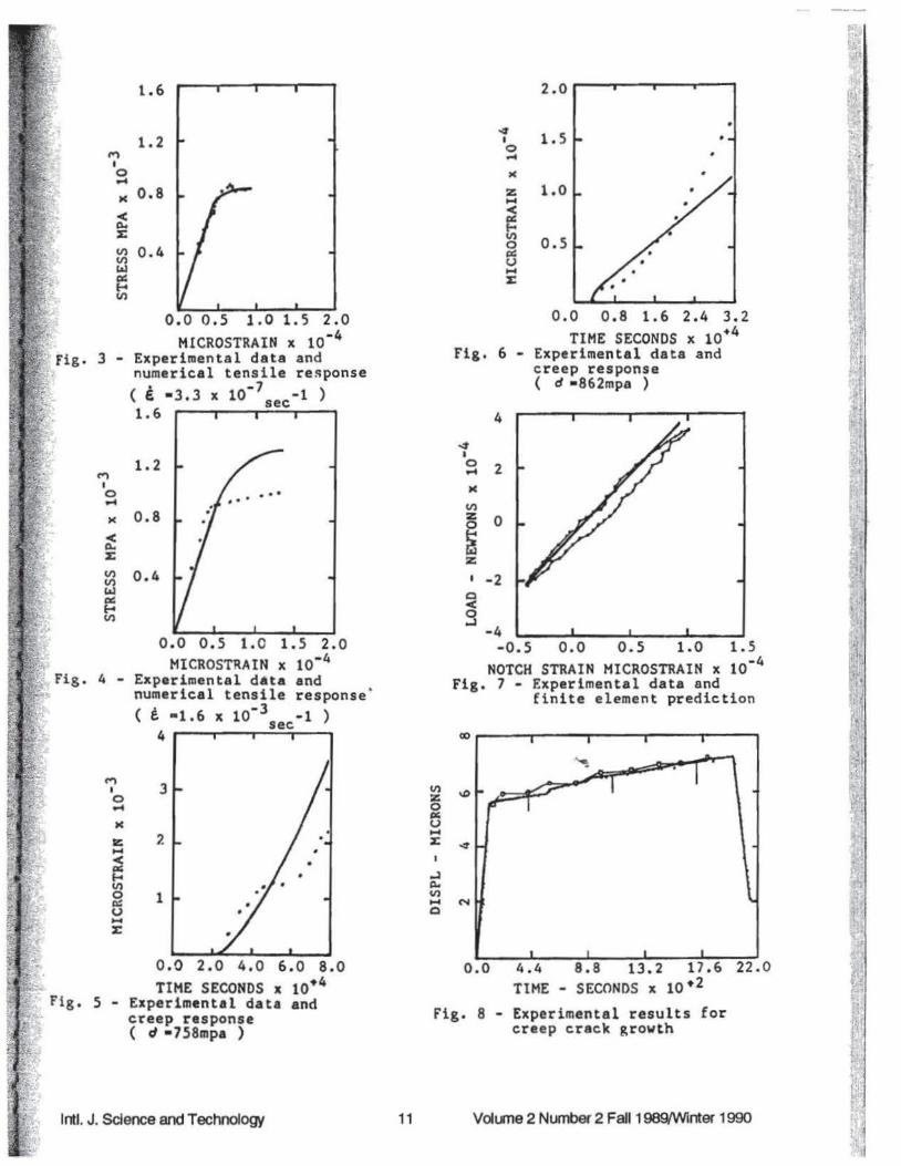
The flnal parameters determined are listed in Table 1 where the values from Milly [4] are also listed Figures 3 4 5 and 6 show the response curves from the model and the experimental data Agreement in flgures 3 and 4 are reasonable except for the fastest tensile test Figures 5 and 6 are not good but the agreement is considerably better than other comparisons [24] The model modulus of elasticity 172 x 103
MPa is high for this material at this te~perature Other determinaHons place it at 155 x 10 MPa[3) As can be obsaved from figures 3 and 4 the modulus for the experimental data is higher still at the faster rates Nevertheless the Bodner Model describes the results fairly well given tbe wide range of strain rates and the fact that 650deg is near a phase transition
This numerical scheme for identifying the Bodner parameters is straightforward and lends to give better agreement with the response curves than graphical methods The Bodner model does reasonably wen io describing stress-strain curves covering a wide range
4of strain-rates (almost 10 in these experiments) and creep curves Actually it is a stiff requirement to ast a model to cover such a wide variety of material response The eight parameters of the Bodner model give it the requisite range but a unique set of parameters was not obtained In general one can make the following conclusions
( 1)A numerical evaluation of the material variables can be made by using Bodner constitutive theory through a numerical simulation of the tensile and creep response with reasonable curve fitting to tho experimental response
(2)Bodner Constitutive theory is sensitive to the variability of the experimental data Since the stress a is the driving force in the constitutive model special attention should be given to the time data for a smooth (a -t) curve
(3)As in Reference [1] Bodner constitutive theory may need further work to decide on improvements which can be made to include effects that would lead to tertiary creep in the representations
(4)From the fact that the calculated values for some of the variables are different for the same value of fltting error (and they should not be) and from the fact that for some runs 4 and Z1 have the same value (and they should not) it can be recognized that the material variables in Bodners Constitutive model are not well defined More specifically they are not universal which may address that 650deg is near a transition temperature for this material
The finite-element model does a good job of evaluating the theoretical elastic stress concentration K and predicting the notch behavior under low cycle loading at high loads The response at the notch is very complicated given the finite plastic strains generated Figure 7 shows the experimental data aod finite-element prediction for the comparison of measured notch strain with that predicted by the finite element durinsect the first cycle of continuous cyclic loading at 650 C
For further application using the Bodner-Partom state variable material model and model parameters developed from uniaxial test data creep aadt growth in Inconel 718 was analyzed by using the coostanl strain finite element for compact tension specimen (8]
Crack growth behavior identified solely from crack opening displacement measurements made on pre-cracked specimens was analyzed by examining various parameters around the models crack tip 1be
Inti J Science and Technology 8 Volume 2 Number 2 Fall1989tWinter 1990
J-integral was applied and used to predict crack loading and the aack propagation material state was growth initiation Promising results were obtained not the same as the initial state of the uniaxial test
In reviewing the response figure 8 one must keep specimen in mind the initial material uniaxial data The cracked
specimens were actually pre-cracked by fatigue
REFERENCES tBodner S R and Partom Y Constitutive
Equarion for Eastic-Viscoplastic Strain Hardening Materials Journal of Applied Mechanics Trans ASME ~ 385-389 1975
2Stouffer D C A Constitutive Representation for IN-100 Air Force Wright Aeronautical Laboratories AFWAL-TR-81-4039 30 pgs 1981
bull 3Hinnerichs T Nicholas T and Pulayatlo A A Hybrid Experimental-Numerical Procedure for Determining Creep Craclc Growth Rates Engineering Fracture Mechanics 16 265-277 1982
4Milly T M and Allen D H A Comparative Study of Nonlioear Rate-Dependent Medlanical Constitutive Theories for Crystalline Solids at Elevated Temperatures Report AP1-E-5-82-5 Virginia Polytechnic Institute and State University March 1982
5Stouffer D C and Bodner S R A Relationship Between Theory and Experiment for a State Variable Constitutive Equatioo AF WAL-TR-80-4194 Wright-Pattmon Air Force Base OH 1981
6Powell M H D An Effective Method for Finding the Minimum of a Function of Several Variables without Calculating the Derivatives Computer Journal 1 144-162 1964
Domas PA Sharpe WN Jr Ward M and Yau J Benchmark Notch Test for Ufe Prediction NASA-Lewis Research Center NASA CR-165571 220 pgs 1982
8Gupta Nirmalya The Threshold Creep Crack Prediction Using the Finite Element Method Master Thesis in Medlanical Engineering Louisiana State University 1984
Inti J Science and Technology 9 Volume 2 Number 2 F aJI1989(Winter 1990
0193
2 - Finite
This Work
07374
6520
7030
686x10-1
-4682x10
4734
3690
103x104
172x103
Volume 2 Number 2 Faii19891Winter 1990
1905Dia
ti===ittt-J==--~~ I
2540Dia
f 1 - Double-notched specimenlg ) Fig( dimensions in mm
TABLE 1
Constant Units Milly (8)
N 1167
Zo MPa 3130 z MPa 4140 m MPa 243x10-2
A -1 sec -411x10
R 2857
zl MPa 2760
Do sec -1 104
E MPa 165x103
lntJ J Science and Technology 10
I 0 M
lt ~ ~
V) V)
taJ a ~ V)
3 shy
t I 0 )(
lt ~ ~
~ taJ a ~ V)
t I 0
16
12
08
04
oo 05 10 1 5 20 HICROSTRAIN x 10-4
Experimental data and numerical tensile re~ponse
bull -7 )( pound bull33 x 10 sec-1 16
12
0 8
04
oo 05 10 15 2 0 HICROSTRAIN x tobull4
Experimental data and numerical tensile responsemiddot ( t bull16 X 10-J -1 )sec4 r-~r-~_y_
2o
4 I 1 5 0 )(
z 10 ltex f-o
0 V)
05 p u ~
0 0 0 8 16 24 32 TIME SECONDS x 10bull4
Fig 6 - Experimental data and creep response ( d bull862mpa )
4
2
0
-2
-4 -05 oo 05 10 15
NOTCH STRAIN MICROSTRAIN x 10middot4
Fig 7 - Experimental data and finite element prediction
4 I s
M
V)
~
~ z I
c lt 3
N
oo 20 40 60 80 00 44 88 132 176 22 0 TIME SECONDS x tobull4 TIME - SECONDS x 10 bull2
5 - Experimental data and Fig 8 - Experimental results forcteep response creep crack growth( d bull758mpa )
Inti J Science and Technology 11 Volume 2 Number 2 Faii1989Wlnter 1990
for example the coostaot strain triangular elements hybrid elements and higher order isoparametric elements For linear elasticity the mathematical development of these elements is simple Since the coostant strain triangular elements have advantages of being simple and economical they were selected to be employed in this study The e~tic-plastic code was used in the numerical determination of Lbe elastic stress concentration (Kc) for benchmark notched specimen under constant tensile load and for the elastic-plastic response of that specimen for cyclic loading
Domas Sharpe Ward and Yau [7] in the analytical task of their study used the finite element method and calculated stress and strain at element centroids for good estimation of tbe elastic stress concentration factor (Kc)
Hennerichs (3] incorporated the Bodner constitutive model into a constant-strain triangular elements model to analyze creep aack growth in a nickel alloy at 1350F
The Constitutive Theory of Bodner and Par1om The constitutive theory of Bodner a(l) is based ooshy
the assumption of small strain and that the total strain rate pound t(t) is separable into elastic (reversible) pound c(t) and plastic (irreversible) ~ P(t) components both non-zero for all loadingunloading conditions
f I (t) bull f ~ (t) + poundP (t) (1) where
e P(t) shy a(t)~ (2)
For the plastic strain rate ep(t) the specific representation used by Bodner and Partom is given by
eP(t) bull _1_ pound1 Do ex [ (Z(t) ) 211 (n+l)) (3)V3 o(t) p 2 o(t) n
where o (t)=The current value of the stress
0 0 =a constant representing the limiting value of the plastic strain rate in shear Generally it is taken at 104 sec- except for conditions of very bigb rates of strain
n =a constant related t vi soosity of the dislocation motion It contro~ the strain rate sensitivity
Z(t) =the plastic state variable measure of the overall res~ce to plastic flow that i1 hardness
The evolution equation ie history dependence of the plastic state variable is generally sought in the form of a differential equation for the hardening rate Z that depends on stress temperature and hardness Z A more specific representation is based on the concept that only the plastic rate of working wP and
current hardness Z control the rate of hardening The complete expression for Z can be written as [11 middot Z = Zt- (Zt - Zo) exp (-mWp) or (Z - Zt) = (Zt - Zo) exp(-mWp)
where m =a material constant controlling the rate of woeki
hardening 1bull
Zt =the saturation value of Z for large Wp ie_ il is J the maximum value of Z taken to be constant middot ~ =the initial value of Z corresponding to tb~~
reference state from which Wp is measured Bounds are (0 s Zo s Z1)middot I
Wp is defined by the differential equation 1 middot~ bulltmiddotmiddot
P bullp z~coveryW - oe- + ____
m(Z1 - Z) (5) l ~
to give ti ~ middot p r middotp tlrecovery
W bull J o amp dt + J(Z _ Z) dt 1
where
z Zmiddot 1Z ~laquoOW) bull -AZt (- )
1
Therefore the complete differential expression or~ is written as
Z bull m(Z1- Z) WP -AZ1 (-- Z)Z1
where J~ t I bull
A =the coefficient controlling the rate of hardeJ t~ 1 recovery bull bull i
r =the exponent controlling lbe rate of bardenin - middot ~ recovery l
Z1 =the state variable value corresponding to the complete non-work hardened condition a functioo of temperature
In (8) the second term is hardening recovery negligible during brief load histories but for loog lime response such as aeep the second term is necessary middot During a teosile test fast compared to aeep equali~ (8) reduces to the first term only For a tensile test equation (8) becomes
z bull m(Z1- Z) WP (9) In lbis case wP is determined by only
Irtf J Science and Technology 6
In order to determine the viscoplastic material constants in these constitutive equations the constants are considered to be in two groups creep response and short time response The short time response constants are Do n m Zo and Z1 and they are determined based on stress-strain test data The creep
middot response constants are Zt r A and they are determined based on data from at least two creep tests at two different stress levels Step-by-step theoretical
-~ evaluation of tbe material paramete~ was developed _ by Bodner (1] for Rene 95 and by Stouffer (2] for In
100 Also Stouffer and Bodner [5] studied the relationship between theory and experiment for the state variable constitutive equation Therefore to
middot complete the study of the constitutive equations a numerical evaluation of the material paramete~ was
middot undertaken
Numerical Evaluation or the Material Parameters middot A numerical study of nonlinear time dependent material was considered where the material variables are numerically calculated using a direct curve fitting technique
In general the Bodner material parameters are dependent on temperature but by performing the
middot material characterization tests (stress-strain and creep) at the same t~mperature that the Bodner model will be applied the temperature dependence is suppressed
To determine the Bodner variables (n Zo Zb m A r Zt and Do) numerically we consider the measured
- and the simulation of the plastic strain For the
evaluation of simulated poundP (t) the total strain rate is considered the sum of elastic and plastic strain rates
(1)
where
pounde(t) bull a(t)IE (2)
Therefore we can rewrite equation (1) in the form
poundP(t) - pound1(t) - Ot)I E (11)
where a (t) is extracted from the data
For the evaluation of theoretical poundP we consider the flow law
~ poundP(t)- JS (12)
where S is the deviatoric stress and A is a scalar function of the state of the materiaL
k =k(X) where
lt X gt =ltnZoZtmArZiDogt Equation (12) becomes
poundP(t) bull A(X) S(t)
and
E 1(t) - E
1(0) +Ipound p(tdt+ if
where pound 1(0) is taken from tbe data
Now let
Qbull L W(t) (eodel - pound~a)2 Data
where w(t) is a positive weight function and
( E ~odel - e ~) is the time domain strain error Q
was minimized in a computerized numerical scheme by varying values of the material coefficients In this analysis a Runge Kutta (fourth order) algorithm was employed for the numerical time integration of the Bodner equations in the following system
trP Z -Z rZbullm(Zt-Z) w -AZ1 t-z-) (8)
(10)
(12)
I j
z2P 2 1
D2
- D exp [-(-) (n+- )] (17) I~ o 312 n n
rwhere J2 is the second stress invariant and equation middot
(17) is from reference (1]
Using a variant of Pbwells (6] search algorithm ~coupled with the integral square error function the specific material variables for the Bodner model were determined to best fit the tensile and creep data Tbe~men~JDa~
In the experimental part of this research a group of tensile and creep tests were performed for lncooel 718 at 650degC The Bodner model coupled with this set of data was employed to determine the material variables of Incooel 718 to best fit the data
To belp eliminate inconsistencies in data the same specimen geometry was used for all tests A drawing of the button-head specimen used in this study is presented in figure 1
All experiments were performed in an electrohydraulic testing machine equipped with a
(13)
(14)
(15)
middotbullt J
(16)
Inti J Science and Technology 7 Volume 2 Number 2 Faii1989Winter 1990 I
special high-temperature furnace Special attention was given to the alignment of the specimen to minimize the eccentricity of the load and to obtain a uniform temperature profile in the test section The machine was run under strain control The data (stress strain lime) was obtained by using the Interferometric StrainDisplacement Gage (ISDG) technique developed and conducted by W N Sharpe
The Elastic-Plastic Finite Element Model The locally written finite-element program
generates constant strain triangular elements with very fine elements in the root of the notch The 2-D program was formulated for plane stress calculaHon and uses the plastic force method to enforce plastic stra in Only one quarter of the specimen was modelled due to symmetry and an automatic mesh generation algorithm permitted easy variation of the total mesh size It was thus possible to easily select the proper balance between mesh fineness and computation time A mesh of 176 nodes and 300 elements was eventually chosen figure 2
Results and Conclusions Uniaxial tensile tests were run at strain rates of 16
X 103 067 X 104 10 X 10middot5 11 X 10-6 and 33 X
wmiddot1 sec middot l 1vo creep tests were run at 758 and 862 MPa The data for each test was smoothed and approximately 20 data points used for each test in the fitting procedure The modulus of elasticity was considered as a parameter increasing the number of constants to be determined to nine Different starling values were tried producing slightly different values of constants though no appreciable difference in the agreement with individual curves A unique set of constants was not already determined to cover the complete data base
The flnal parameters determined are listed in Table 1 where the values from Milly [4] are also listed Figures 3 4 5 and 6 show the response curves from the model and the experimental data Agreement in flgures 3 and 4 are reasonable except for the fastest tensile test Figures 5 and 6 are not good but the agreement is considerably better than other comparisons [24] The model modulus of elasticity 172 x 103
MPa is high for this material at this te~perature Other determinaHons place it at 155 x 10 MPa[3) As can be obsaved from figures 3 and 4 the modulus for the experimental data is higher still at the faster rates Nevertheless the Bodner Model describes the results fairly well given tbe wide range of strain rates and the fact that 650deg is near a phase transition
This numerical scheme for identifying the Bodner parameters is straightforward and lends to give better agreement with the response curves than graphical methods The Bodner model does reasonably wen io describing stress-strain curves covering a wide range
4of strain-rates (almost 10 in these experiments) and creep curves Actually it is a stiff requirement to ast a model to cover such a wide variety of material response The eight parameters of the Bodner model give it the requisite range but a unique set of parameters was not obtained In general one can make the following conclusions
( 1)A numerical evaluation of the material variables can be made by using Bodner constitutive theory through a numerical simulation of the tensile and creep response with reasonable curve fitting to tho experimental response
(2)Bodner Constitutive theory is sensitive to the variability of the experimental data Since the stress a is the driving force in the constitutive model special attention should be given to the time data for a smooth (a -t) curve
(3)As in Reference [1] Bodner constitutive theory may need further work to decide on improvements which can be made to include effects that would lead to tertiary creep in the representations
(4)From the fact that the calculated values for some of the variables are different for the same value of fltting error (and they should not be) and from the fact that for some runs 4 and Z1 have the same value (and they should not) it can be recognized that the material variables in Bodners Constitutive model are not well defined More specifically they are not universal which may address that 650deg is near a transition temperature for this material
The finite-element model does a good job of evaluating the theoretical elastic stress concentration K and predicting the notch behavior under low cycle loading at high loads The response at the notch is very complicated given the finite plastic strains generated Figure 7 shows the experimental data aod finite-element prediction for the comparison of measured notch strain with that predicted by the finite element durinsect the first cycle of continuous cyclic loading at 650 C
For further application using the Bodner-Partom state variable material model and model parameters developed from uniaxial test data creep aadt growth in Inconel 718 was analyzed by using the coostanl strain finite element for compact tension specimen (8]
Crack growth behavior identified solely from crack opening displacement measurements made on pre-cracked specimens was analyzed by examining various parameters around the models crack tip 1be
Inti J Science and Technology 8 Volume 2 Number 2 Fall1989tWinter 1990
J-integral was applied and used to predict crack loading and the aack propagation material state was growth initiation Promising results were obtained not the same as the initial state of the uniaxial test
In reviewing the response figure 8 one must keep specimen in mind the initial material uniaxial data The cracked
specimens were actually pre-cracked by fatigue
REFERENCES tBodner S R and Partom Y Constitutive
Equarion for Eastic-Viscoplastic Strain Hardening Materials Journal of Applied Mechanics Trans ASME ~ 385-389 1975
2Stouffer D C A Constitutive Representation for IN-100 Air Force Wright Aeronautical Laboratories AFWAL-TR-81-4039 30 pgs 1981
bull 3Hinnerichs T Nicholas T and Pulayatlo A A Hybrid Experimental-Numerical Procedure for Determining Creep Craclc Growth Rates Engineering Fracture Mechanics 16 265-277 1982
4Milly T M and Allen D H A Comparative Study of Nonlioear Rate-Dependent Medlanical Constitutive Theories for Crystalline Solids at Elevated Temperatures Report AP1-E-5-82-5 Virginia Polytechnic Institute and State University March 1982
5Stouffer D C and Bodner S R A Relationship Between Theory and Experiment for a State Variable Constitutive Equatioo AF WAL-TR-80-4194 Wright-Pattmon Air Force Base OH 1981
6Powell M H D An Effective Method for Finding the Minimum of a Function of Several Variables without Calculating the Derivatives Computer Journal 1 144-162 1964
Domas PA Sharpe WN Jr Ward M and Yau J Benchmark Notch Test for Ufe Prediction NASA-Lewis Research Center NASA CR-165571 220 pgs 1982
8Gupta Nirmalya The Threshold Creep Crack Prediction Using the Finite Element Method Master Thesis in Medlanical Engineering Louisiana State University 1984
Inti J Science and Technology 9 Volume 2 Number 2 F aJI1989(Winter 1990
0193
2 - Finite
This Work
07374
6520
7030
686x10-1
-4682x10
4734
3690
103x104
172x103
Volume 2 Number 2 Faii19891Winter 1990
1905Dia
ti===ittt-J==--~~ I
2540Dia
f 1 - Double-notched specimenlg ) Fig( dimensions in mm
TABLE 1
Constant Units Milly (8)
N 1167
Zo MPa 3130 z MPa 4140 m MPa 243x10-2
A -1 sec -411x10
R 2857
zl MPa 2760
Do sec -1 104
E MPa 165x103
lntJ J Science and Technology 10
I 0 M
lt ~ ~
V) V)
taJ a ~ V)
3 shy
t I 0 )(
lt ~ ~
~ taJ a ~ V)
t I 0
16
12
08
04
oo 05 10 1 5 20 HICROSTRAIN x 10-4
Experimental data and numerical tensile re~ponse
bull -7 )( pound bull33 x 10 sec-1 16
12
0 8
04
oo 05 10 15 2 0 HICROSTRAIN x tobull4
Experimental data and numerical tensile responsemiddot ( t bull16 X 10-J -1 )sec4 r-~r-~_y_
2o
4 I 1 5 0 )(
z 10 ltex f-o
0 V)
05 p u ~
0 0 0 8 16 24 32 TIME SECONDS x 10bull4
Fig 6 - Experimental data and creep response ( d bull862mpa )
4
2
0
-2
-4 -05 oo 05 10 15
NOTCH STRAIN MICROSTRAIN x 10middot4
Fig 7 - Experimental data and finite element prediction
4 I s
M
V)
~
~ z I
c lt 3
N
oo 20 40 60 80 00 44 88 132 176 22 0 TIME SECONDS x tobull4 TIME - SECONDS x 10 bull2
5 - Experimental data and Fig 8 - Experimental results forcteep response creep crack growth( d bull758mpa )
Inti J Science and Technology 11 Volume 2 Number 2 Faii1989Wlnter 1990