Integrated Geophysical and Geotechnical Subsoil Evaluation for Pre-foundation study of Proposed
Site of Vocational Skill and Entrepreneurship Center at The Polytechnic, Ibadan, Sw, Nigeria
Adejumo S.A,Oyerinde A.O,Aleem M.O
Abstract— An integrated geophysical and geotechnical investigation has been conducted as pre-foundation study at the proposed site of vocational skill and entrepreneurship centre, The Polytechnic, Ibadan, Nigeria. This is aimed at evaluating the competence of the the foundation materials in the near surface formation . The study involved twelve vertical electrical sounding (VES) using schlumberger electrode array and geotechnical laboratory test on six soil samples of the subsoil within the study area. Four distinct geo electric layers were delineated; the top soil, laterite, weathered layer and fractured basement. The layer resistivity and thickness ranges are 87.6-344.3ohm-m and 0.6-2.3m; 129.1-607.3ohm-m and 1.2-8.6m, 27.9-209.9 ohm-m and 6.3 -26..3m and 42.5-613 ohm-m for the four layers respectively. The overburden thickness in the area generally exceed 10m. The percentage passing 0.075mm, Liquid Limit, Plasticity Index, Linear Shrinkage, Natural moisture Content, Maximum Dry Density, Optimum Moisture Content and Unconfined Compressive Strength ranges are 21.3-32.4, 30-38%, 6.4-8.9%, 0.8-5.7%, 7.5-11.7,1.68-1.83g/cm3, 16-18% and 130 – 145KN/m2 respectively. In the area the subsoil within or on which civil engineering structure can be placed are composed mainly of clayey sand and laterite with a mean resistivity value of 240 ohm-m and all geotechnical parameters were within specification for subsoil foundation materials. It can be concluded therefore that the subsoil within the study area are generally competent as foundation material to host the proposed structure. Index Terms— civil engineering structure, competence, geeoelectric layers, geophysical, pre-foundation, Schlumberger electrode array, Vertical Electrical Sounding(VES)
—————————— ——————————
1 INTRODUCTION In recent times, the rate of failure of buildings and other engineering structures in Nigeria is alarming and thus requires an urgent attention. Apart from the enormous loss of financial investment, failure of building had always been accompanied by loss of valuable properties and lives as well as many causalities. Among general reason advanced to have been responsible for the occurrence of this ugly incident include poor quality of building material, salinity and old age of buildings (Oyedele et. al 2011). Little or no consideration is given to the subsurface conditions of the soils or rock on which the buildings are sited. Since nearly all engineering structure erected on the earth surface have its own substructure that are supported by soil and rocks, then it becomes highly essential to have adequate knowledge of the nature of the soil or rock supporting the substructure for structural integrity, safety and durability of the proposed structure on the site before the commencement of actual construction work. Hence the need for this work. Foundation evaluation of a new site is necessary so as to provide
subsurface and aerial information that normally assist civil engineers, builders and town planners in the design and sitting of foundations of civil engineering structures (Omoyoloye, et.al, 2008). The conventionally methods such as cone penetrometer test, and other geotechnical methods usually used by the civil and building engineers in assessing the strength of materials for the support of engineering structure are cost expensive, time consuming and not fully effective as they might not give adequate information about the entire area and good depth of investigation. Therefore, it is imperative to complement the conventional methods with cost effective geophysical method which commonly applied in engineering site investigation. (Olorunfemi et. al, 2002, Akintorinwa and Adesoji, 2009 and Akintorinwa and Adeusi, 2009). Engineering geophysics gives detail information on the degree of competence of the subsoil in foundation engineering (Ofomola et. al, 2009). Careful geophysical studies that are supported by improved during techniques yield very favorable results even in the problematic areas of the basement complex (Offordile, 1983). The choice of the geophysical methods is usually determined by the geologic set up and the existence of significant contrast in the physical properties of the subsurface layers (Olorunfemi et.al, 2002). In the present study, electrical resistivity method of geophysics had been integrated with geotechnical investigation in evaluating the competence of the subsoil at the proposed permanent site of Vocational Skills and Entrepreneurship Centre at The Polytechnic, Ibadan North Campus.
———————————————— • Adejumo S.A is a lecturer in the department of Geology, The Polytechnic,
Ibadan and currently pursuing PhD program in Applied Geophysics in University of Ibadan ,Nigeria. E-mail: [email protected]
• Oyerinde A.O is a lecturer in the department of Geology, The Polytechnic, Ibadan and currently pursuing PhD program in Applied Geophysics in University of Ibadan ,Nigeria. E-mail: [email protected]
• Aleem M.O is lecturer in the department of Quantity surveying, The Polytechnic,Ibadan,Nigeria
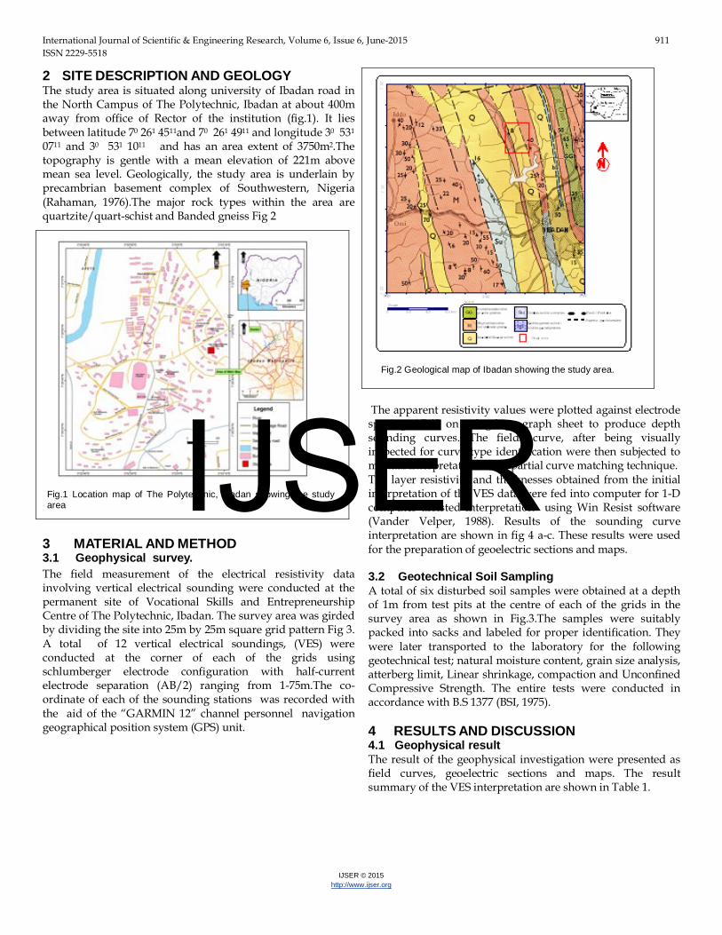
2 SITE DESCRIPTION AND GEOLOGY The study area is situated along university of Ibadan road in the North Campus of The Polytechnic, Ibadan at about 400m away from office of Rector of the institution (fig.1). It lies between latitude 70 261 4511and 70 261 4911 and longitude 30 531 0711 and 30 531 1011 and has an area extent of 3750m2.The topography is gentle with a mean elevation of 221m above mean sea level. Geologically, the study area is underlain by precambrian basement complex of Southwestern, Nigeria (Rahaman, 1976).The major rock types within the area are quartzite/quart-schist and Banded gneiss Fig 2
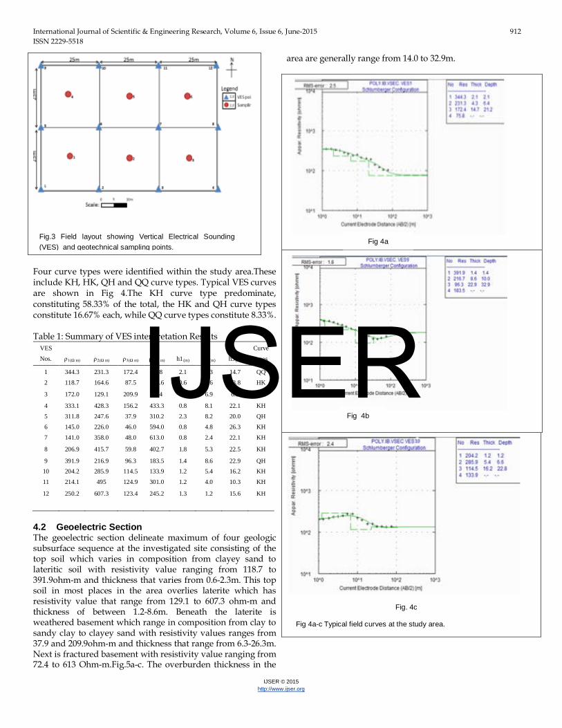
3 MATERIAL AND METHOD 3.1 Geophysical survey. The field measurement of the electrical resistivity data involving vertical electrical sounding were conducted at the permanent site of Vocational Skills and Entrepreneurship Centre of The Polytechnic, Ibadan. The survey area was girded by dividing the site into 25m by 25m square grid pattern Fig 3. A total of 12 vertical electrical soundings, (VES) were conducted at the corner of each of the grids using schlumberger electrode configuration with half-current electrode separation (AB/2) ranging from 1-75m.The co-ordinate of each of the sounding stations was recorded with the aid of the “GARMIN 12” channel personnel navigation geographical position system (GPS) unit.
The apparent resistivity values were plotted against electrode spacing AB/2 on a log-log graph sheet to produce depth sounding curves. The fields curve, after being visually inspected for curve type identification were then subjected to manual interpretation using partial curve matching technique. The layer resistivity and thicknesses obtained from the initial interpretation of the VES data were fed into computer for 1-D computer assisted interpretation using Win Resist software (Vander Velper, 1988). Results of the sounding curve interpretation are shown in fig 4 a-c. These results were used for the preparation of geoelectric sections and maps. 3.2 Geotechnical Soil Sampling A total of six disturbed soil samples were obtained at a depth of 1m from test pits at the centre of each of the grids in the survey area as shown in Fig.3.The samples were suitably packed into sacks and labeled for proper identification. They were later transported to the laboratory for the following geotechnical test; natural moisture content, grain size analysis, atterberg limit, Linear shrinkage, compaction and Unconfined Compressive Strength. The entire tests were conducted in accordance with B.S 1377 (BSI, 1975). 4 RESULTS AND DISCUSSION 4.1 Geophysical result The result of the geophysical investigation were presented as field curves, geoelectric sections and maps. The result summary of the VES interpretation are shown in Table 1.
Fig.1 Location map of The Polytechnic, Ibadan showing the study area
Fig.2 Geological map of Ibadan showing the study area.
Four curve types were identified within the study area.These include KH, HK, QH and QQ curve types. Typical VES curves are shown in Fig 4.The KH curve type predominate, constituting 58.33% of the total, the HK and QH curve types constitute 16.67% each, while QQ curve types constitute 8.33%. Table 1: Summary of VES interpretation Results
4.2 Geoelectric Section The geoelectric section delineate maximum of four geologic subsurface sequence at the investigated site consisting of the top soil which varies in composition from clayey sand to lateritic soil with resistivity value ranging from 118.7 to 391.9ohm-m and thickness that varies from 0.6-2.3m. This top soil in most places in the area overlies laterite which has resistivity value that range from 129.1 to 607.3 ohm-m and thickness of between 1.2-8.6m. Beneath the laterite is weathered basement which range in composition from clay to sandy clay to clayey sand with resistivity values ranges from 37.9 and 209.9ohm-m and thickness that range from 6.3-26.3m. Next is fractured basement with resistivity value ranging from 72.4 to 613 Ohm-m.Fig.5a-c. The overburden thickness in the
area are generally range from 14.0 to 32.9m.
Fig.3 Field layout showing Vertical Electrical Sounding (VES) and geotechnical sampling points. Fig 4a
Fig 4b
Fig. 4c Fig 4a-c Typical field curves at the study area.
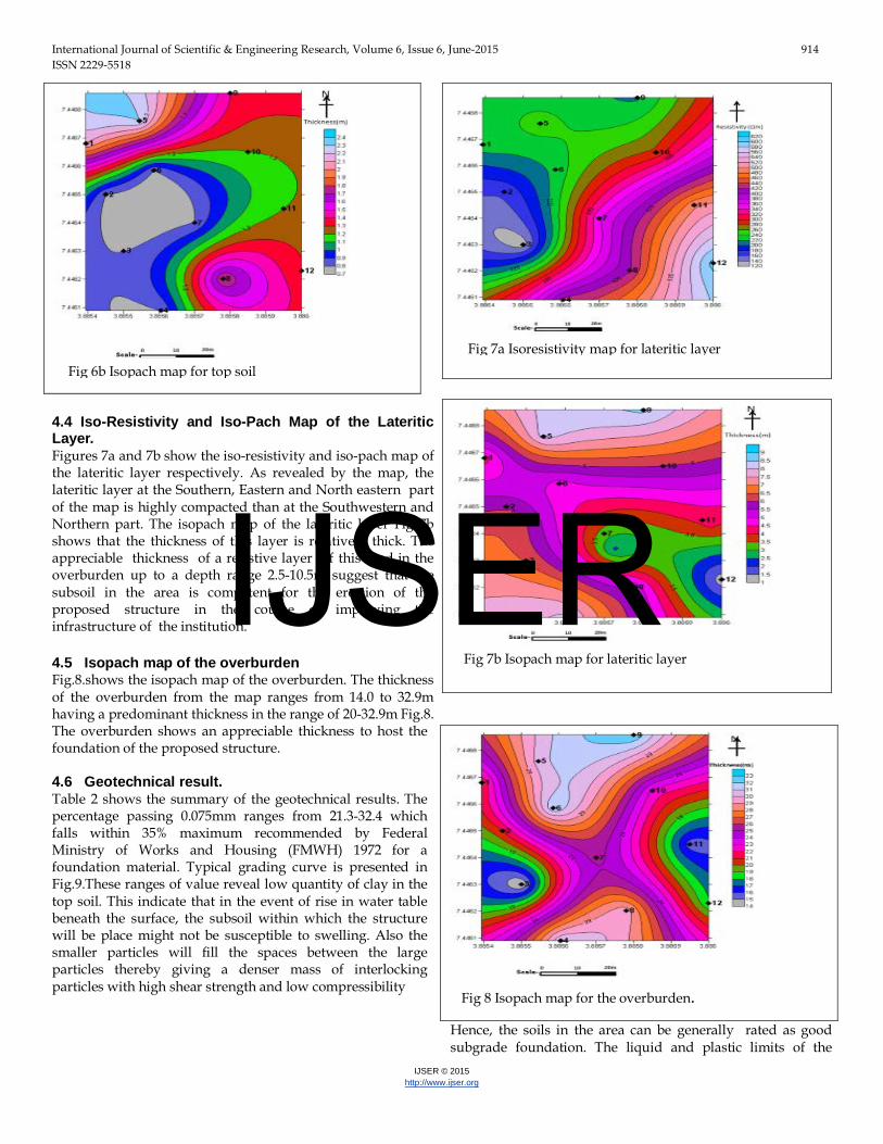
4.3 Iso-resistivity and Iso-pach Map of the Top soil. The iso-resistivity and isopach map of the top soil are respectively shown in Fig 6a and 6b .The top soil as revealed by the iso-resistivity map composed of clayey sand at the western and central part and lateritic portion at the southern, Northern and Eastern part of the map. The predominant resistivity value of this layer ranges from 118.7 to 391.9ohm-m. The isopach map of the top soil Fig 6b shows that the top soil in the area are generally relatively thin with the highest thickness up to 2.3m in the Northeastern part of the area. The top soil thickness as shown in the map generally < 2.5m Fig 6b
Fig 5b Geoelectric section across VES 5, 6, 7 and 8.
Fig 5c Geoelectric section across VES 9, 10, 11 and 12.
Fig 5a Geoelectric section across VES 1, 2 ,3 and 4
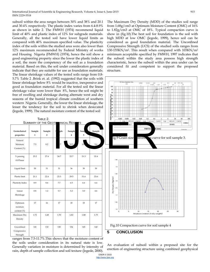
4.4 Iso-Resistivity and Iso-Pach Map of the Lateritic Layer. Figures 7a and 7b show the iso-resistivity and iso-pach map of the lateritic layer respectively. As revealed by the map, the lateritic layer at the Southern, Eastern and North eastern part of the map is highly compacted than at the Southwestern and Northern part. The isopach map of the lateritic layer Fig 7b shows that the thickness of this layer is relatively thick. The appreciable thickness of a resistive layer of this kind in the overburden up to a depth range 2.5-10.5m suggest that the subsoil in the area is competent for the erection of the proposed structure in the course of improving the infrastructure of the institution. 4.5 Isopach map of the overburden Fig.8.shows the isopach map of the overburden. The thickness of the overburden from the map ranges from 14.0 to 32.9m having a predominant thickness in the range of 20-32.9m Fig.8. The overburden shows an appreciable thickness to host the foundation of the proposed structure. 4.6 Geotechnical result. Table 2 shows the summary of the geotechnical results. The percentage passing 0.075mm ranges from 21.3-32.4 which falls within 35% maximum recommended by Federal Ministry of Works and Housing (FMWH) 1972 for a foundation material. Typical grading curve is presented in Fig.9.These ranges of value reveal low quantity of clay in the top soil. This indicate that in the event of rise in water table beneath the surface, the subsoil within which the structure will be place might not be susceptible to swelling. Also the smaller particles will fill the spaces between the large particles thereby giving a denser mass of interlocking particles with high shear strength and low compressibility
Hence, the soils in the area can be generally rated as good subgrade foundation. The liquid and plastic limits of the
subsoil within the area ranges between 30% and 38% and 20.1 and 30.4% respectively. The plastic index varies from 6.4-8.9% as shown in table 2. The FMWH (1974) recommend liquid limit of 40% and plastic index of 12% for subgrade materials. Generally, all the tested soil have lower liquid limits as compared with 40% maximum specified value. The plasticity index of the soils within the studied area were also lower than 12% maximum recommended by Federal Ministry of works and Housing Nigeria (FMWH) (1974), hence the soil show a good engineering property since the lower the plastic index of a soil, the more the competency of the soil as a foundation material. Based on this, the soil under consideration generally indicate that they are suitable for use as foundation materials. The linear shrinkage values of the tested soils range from 0.8-5.7% Table 2 .Brink et. al. (1992) suggested that the soils with linear shrinkage below 8% would be inactive, inexpensive and good as foundation material. For all the tested soil the linear shrinkage value were lower than 8%, hence the soil might be free of swelling and shrinkage during alternate west and dry seasons of the humid tropical climate condition of southern western Nigeria. Generally, the lower the linear shrinkage, the lesser the tendency for the soil to shrink when desiccated (Jegede, 1999). The natural moisture content of the tested soil TABLE 2. SUMMARY OF THE GEOTECHNICAL RESULTS
Geotechnical
properties
Sample
1
Sample
2
Sample
3
Sample
4
Sample
5
Sample
6
Natural
Moisture
Content (%)
7.5
8.2
11.7
10.5
10.9
9.4
% passing
0.075mm
25.2 27.4 24.7 22.7 21.3 32.4
Liquid limit
30 31 31 36 38 30
Plastic limit 21.1 22.4 23.3 29.5 31.4 23.6
Plasticity Index
8.9 8.6 7.7 6.5 6.6 6.4
Linear
Shrinkage
0.8 1.2 5.7 3.2 3.0 4.6
Optimum
moisture
content (%)
17 16 17 18 18 17
Maximum Dry
Density
1.72 1.68 1.70 1.82 1.80 1.73
Unconfined
Compressive
Strength
141
132 130 136 145 142
ranges from 7.5-11.7%.This shows that the moisture content of the soils under consideration in its natural state is low. Generally variation in moisture is determined by intensity of rain, depth of sample collection and soil texture (Jegede, 2000).
The Maximum Dry Density (MDD) of the studies soil range from 1.68g/cm3 at Optimum Moisture Content (OMC) of 16% to 1.82g/cm3 at OMC of 18%. Typical compaction curve is show in (fig.10).The best soil for foundation is the soil with high MDD at low OMC (Jegede, 1999), hence soil can be considered as good foundation material. The Unconfined Compressive Strength (UCS) of the studied soils ranges from 130-155KN/m2. This result when compared with 103KN/m2 minimum acceptable specified by FMWH, 1997 indicates that the subsoil within the study area possess high strength characteristic, hence the subsoil within the area under can be considered fit and competent to support the proposed structure.
5 CONCLUSION An evaluation of subsoil within a proposed site for the erection of engineering structure using combined geophysical
Fig.9 Grain size distribution curve for soil sample 3.
and geotechnical approach were carried out. This was to provide information on the geologic sequence, nature and competence of the subsoil in the area. To achieve these twelve Vertical Electrical Sounding (VES) stations were occupied and this was corroborated with geotechnical laboratory test on six soil samples collected within the study area. The investigation identified four geologic layer/sequence comprising the top soil, lateritic layer, weathered layer and fractured basement. The composition of the top soil is mostly clayey sand and laterite with a mean resistivity value of 236.10hm-m. The thickness of the top soil layer range from 0.8-2.3m. The lateritic layer which underlies the top soil has a mean resistivity value of 317.1Ohm -m and thickness value which range from 1.2 to 8.6m. These two layers constitute the subsurface geologic sequence within which normal civil engineering foundation is founded. The overburden in the area is relatively thick and there are no indication of any major bedrock structural features such as faults which can aid subsidence in the area. The geotechnical results shows that the soils are generally of low clay content as revealed by the percentage passing 0.075mm.
The geotechnical parameters determined for all the soils fall within the specification recommended by for foundation material by FMWH, 1972. For instance the geotechnical results show that the percentage passing 0.075mm generally less than 35% indicating that the soil has relatively low clay content. This was corroborated by the clayey sand and lateritic nature of the top soil as revealed by the geophysical results. It can be therefore concluded that, the subsoil on or within which the proposed engineering structure will be founded within the study area are generally competent.
REFERENCES [1] Akintorinwa, O.J and Adesoji, J.I 2009. “Application of
Geophysical and geotechnical investigations in Engineering site Evaluation”. International Journal of physical sciences, Vol. 4 (8).pp 443-454.
[2] Akintorinwa, O.J and Adeusi, F.A 2009. “Integration of Geophysical and Geotechnical Investigations for a proposed lecture Room complex at the Federal University of Technology, Akure, SW, Nigeria”. Ozean journal of Applied Sciences 2(3), Pp241-254.
[3] Brink, A.B.D., Parridge, J.C. and Williams, A.A.B 1992. “Soil survey for Engineering, Claredon,Oxford”.
[4] British Standards Institution (1975). BSI 1377: Methods of Testing Soils for civil Engineering purpose pp. 59-276.
[5] Federal Ministry of Works and Housing Nigeria (1974): specification for roads and bridges 26p.
[6] Federal Ministry of Work and Housing Nigeria (2000): specification for roads and bridges, Vol. 2.
[7] Federal Ministry of Works and Housing, Nigeria (1997).General specification for Road and Bridges.Federal Highway Department,Vol.II,pp 145-284.
[8] Jegede,G. (1999): Engineering Geological Significance of the superficial Deposits in carington Hill Area,country conc, Ireland. Nig. Journal of sciences Vol. 28: Pp 153-158.
[9] Jegede,G.(2000): Effect of soil properties on pavement failure along
the F209 highway at Ado-Ekiti, Southern western Nigeria. Journal of construction and building materials Vol. 14, Pp.311-315.
[10] Offordile, M.E 1983. “The occurrence of of exploration on groundwater in Nigeria Basement rocks. Nigeria journal of Mining and Geology Vol. 20, 131-146.
[11] Ofomola, M.O Adiat, K.A.N, Olagunju, G.M. and Ako, B.D 2009. “Integrated Geophysical methods for post foundational studies, Obanla staff Quarters of the federal university of technology, Akure, Nigeria”. Pacific Journal of science and Technology. 10(2): 93-111.
[12] Olorunfemi, M.O, Ojo, J.S and Ojelabi, E.A.2002. “Geophysical site investigation of the premises of Idu Flow station. Nigeria Agip company (NAOC) Limited. (for multipurpose oil services company limited, Port Harcourt) ”. Technical report.
[13] Omoyoloye, N.A.,Oladapo,M.I and Adeoye,O.O. 2008.“Engineering Geophysical study of Adagbakuja Newtown Development, South Western Nigerian”. Medwell online journal of Earth Science, Vol. 2(2), Pp. 55-63.
[14] Oyedele, K .F. Oladele, S.,andAdedoyin,O.2011.“Application of Geophisical and Geotechnical methods to site characterization for construction purpose at Ikoyi, Lagos, Nigeria” Journal of Earth sciences and Geotechnical Engineering, Vol. 1, No 1, 87-100.
[15] Rahaman, M.A (1976): Review of the basement Geology of south western Nigeria in Geologic of Nigeria. Elizabethan publishing company: Nigeria Pp.44-58.