INTERNSHIP REPORT SUBMISSION GRAMEENPHONE LTD GAZIPUR SUB CENTRE JHAJHOR,NATIONAL UNIVERSITY GAZIPUR. Prepared For Dr. M. Mofazzal Hossain Intern Advisor Professor Department of ECE Prepared By Samiour Rahaman 2011-3-58-028 Date of Submission: April 18, 2016
Transcript
INTERNSHIP REPORT SUBMISSION
[[G G G
GRAMEENPHONE LTD GAZIPUR SUB CENTRE JHAJHOR,NATIONAL UNIVERSITY GAZIPUR.
Prepared For Dr. M. Mofazzal Hossain Intern Advisor Professor Department of ECE
Prepared By Samiour Rahaman 2011-3-58-028
Date of Submission: April 18, 2016
Acceptance
This internship report is submitted to the Department of Electronics
&Communications Engineering East West University, Dhaka in partial fulfillment
of the requirement for the degree of B.Sc in Electronics & Telecommunications
Engineering under complete supervision of undersigned.
Dr. M. Mofazzal Hossain Md. Dudu Mia
Professor Manager
Department of Electronics &Communications Engineering, Grameenphone LTD.
Gazipur Sub-center
East West University,
Aftabnagar, Dhaka, Bangladesh
1 | P a g e
TABLE OF CONTENTS
Serial topic page
Chapter-1 Introduction 1-4
1.1 Origin of the Report 2
1.2 Objective of the Report 2
1.3 Scope of the Report 3
1.4 Methodology 3
1.5 Limitation 4
Chapter-02 Background of the Organization
5-10
2.1 An Overview of the Organization
6
2.2 Share Holders 6
2.3 Telenor Mobile Communications
7
2.4 Grameen Telecom 8
2.5 Company Mission 8
2.6 Company’s Objectives 9
2.7 Company’s strategy 9
2.8 Company’s Value 10
Chapter -3 Microwave link PNMS (Paso link Network Management
System)
11-21
3.1 System description 12
3.2 Functional description and components
12
3.3 IDU and ODU Components 15
3.4 IDU functional description 15
3.5 ODUFunctionalDescription 17
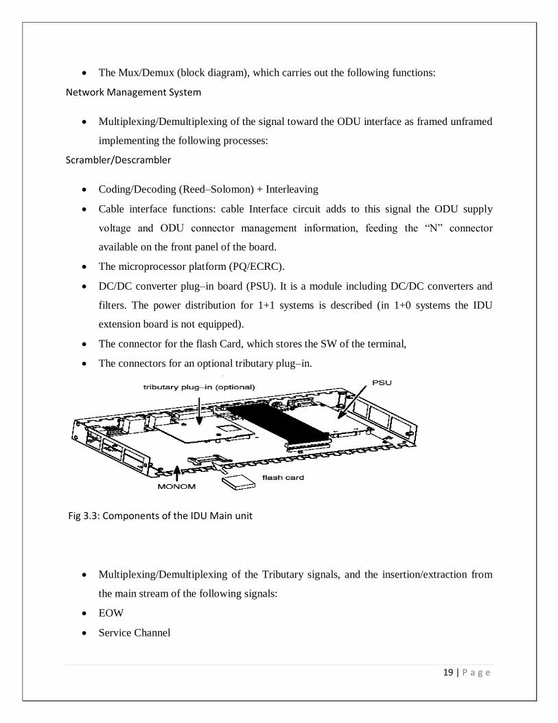
3.6 IDU (Indoor Unit) 19
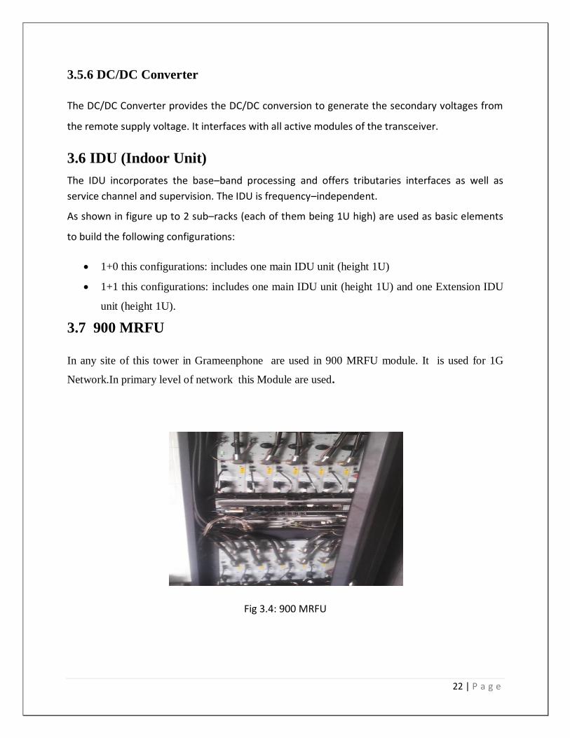
3.7 900 MRFU 19
3.8 1800 MRFU 20
3.9 2100 MRFU 20
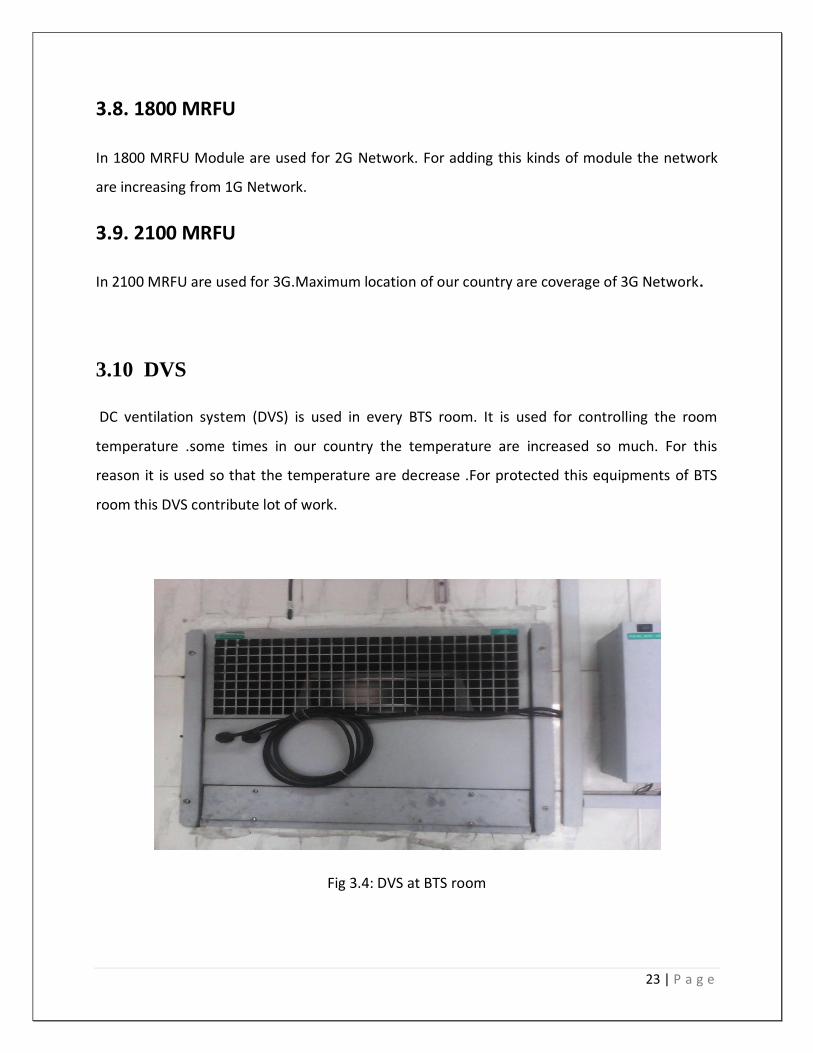
3.10 DVS 20
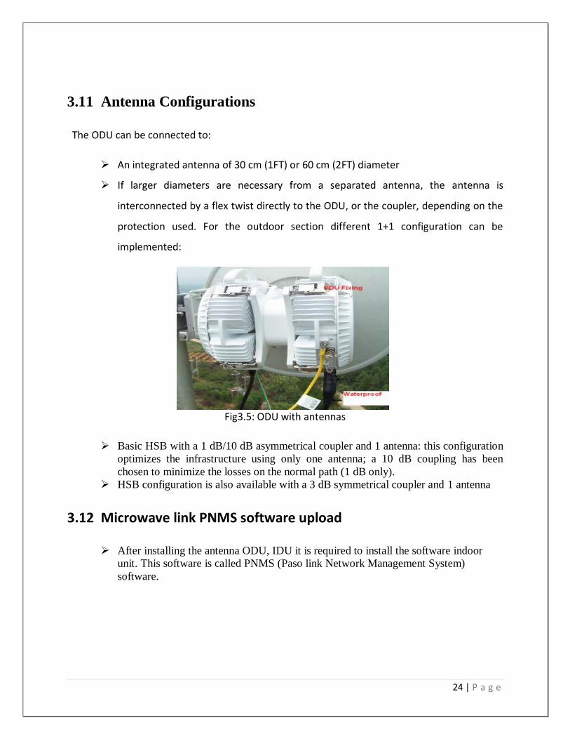
3.11 Antenna Configurations 21
Chapter -04 3G Network 22-29
4.1 3G services 23
4.2 Benefit of 3G 23
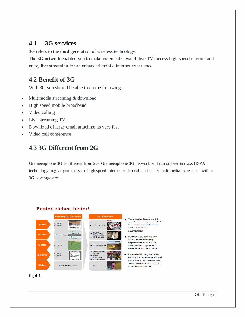
4.3 3G Different from 2G 23
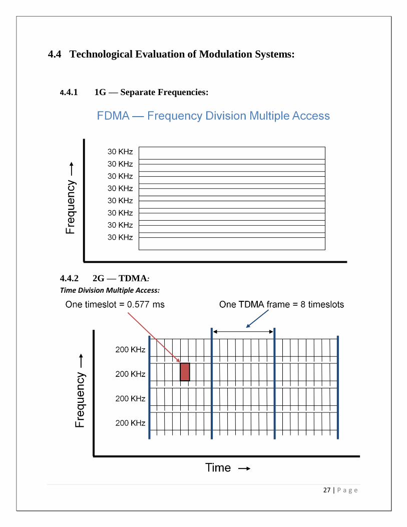
4.4 Technological Evaluation of 24
2 | P a g e
Modulation Systems
4.5 2G & 3G — CDMA 25
4.6 Universal Mobile Telecommunication System
25
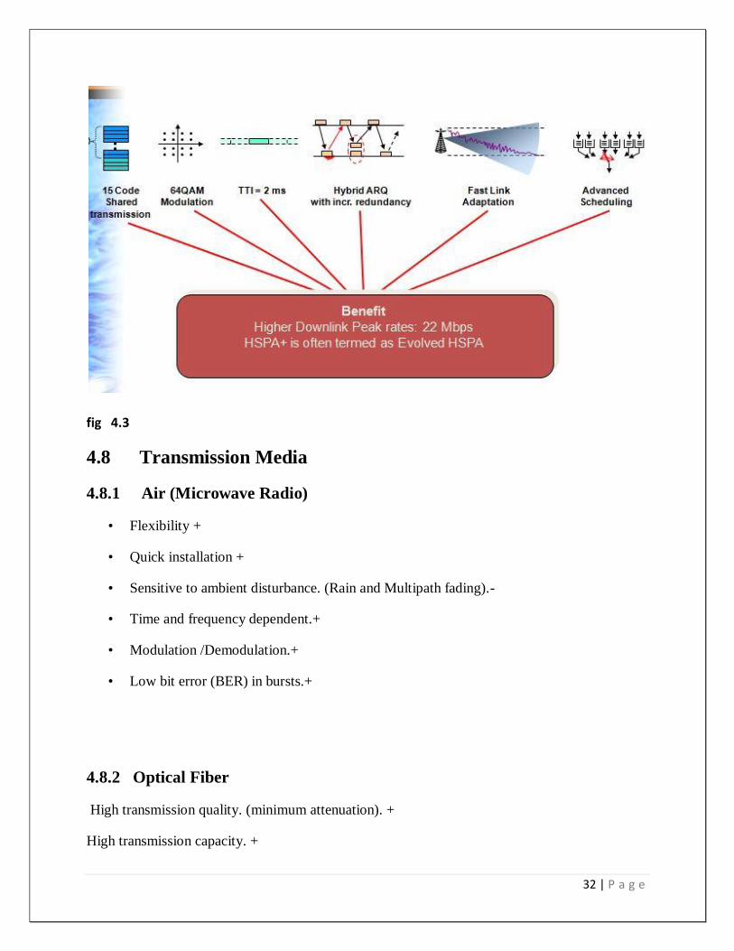
4.7 Introduction to HSPA 25
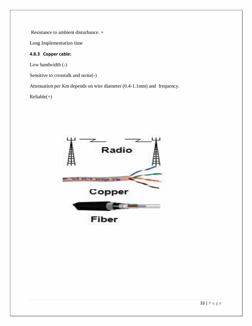
4.8 Transmission Media 28
Chapter -5 Global System for Mobile communication
30-46
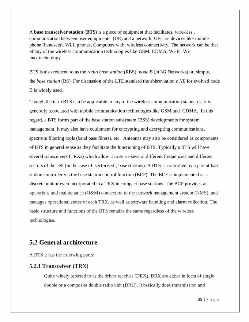
5.1 Base transceiver station (BTS) 31
5.2 General architecture 32
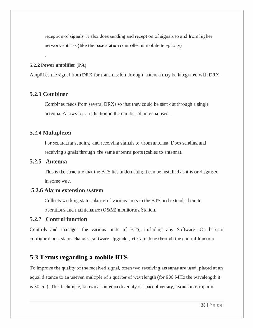
5.3 Terms regarding a mobile BTS 33
5.4 GSM Network Architecture 33
5.5 Topics 34
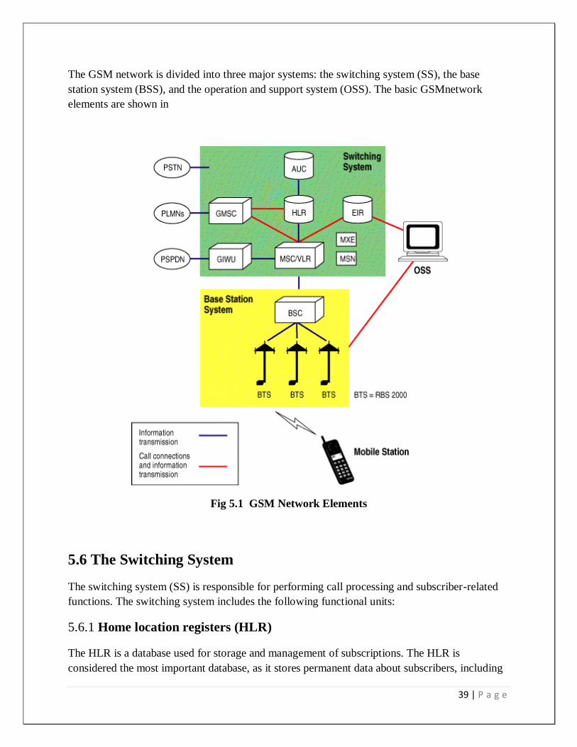
5.6 The Switching System 36
5.7 TRANSMISSION NETWORK 37
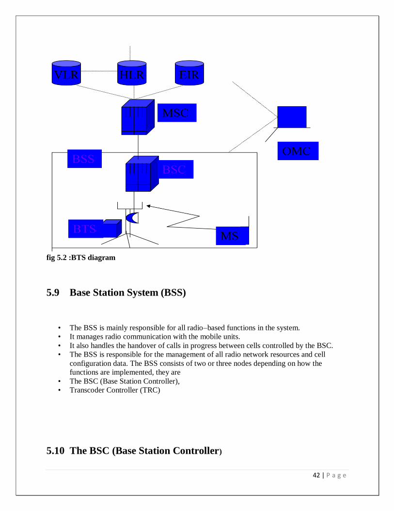
5.8 DIAGRAM 38
5.9 Base Station System (BSS) 38
5.10 The BSC (Base Station Controller)
39
5.11 Transcoder Controller (TRC) 39
5.12 BSS 39
5.13 Microwave link from one to another BTS tower
40
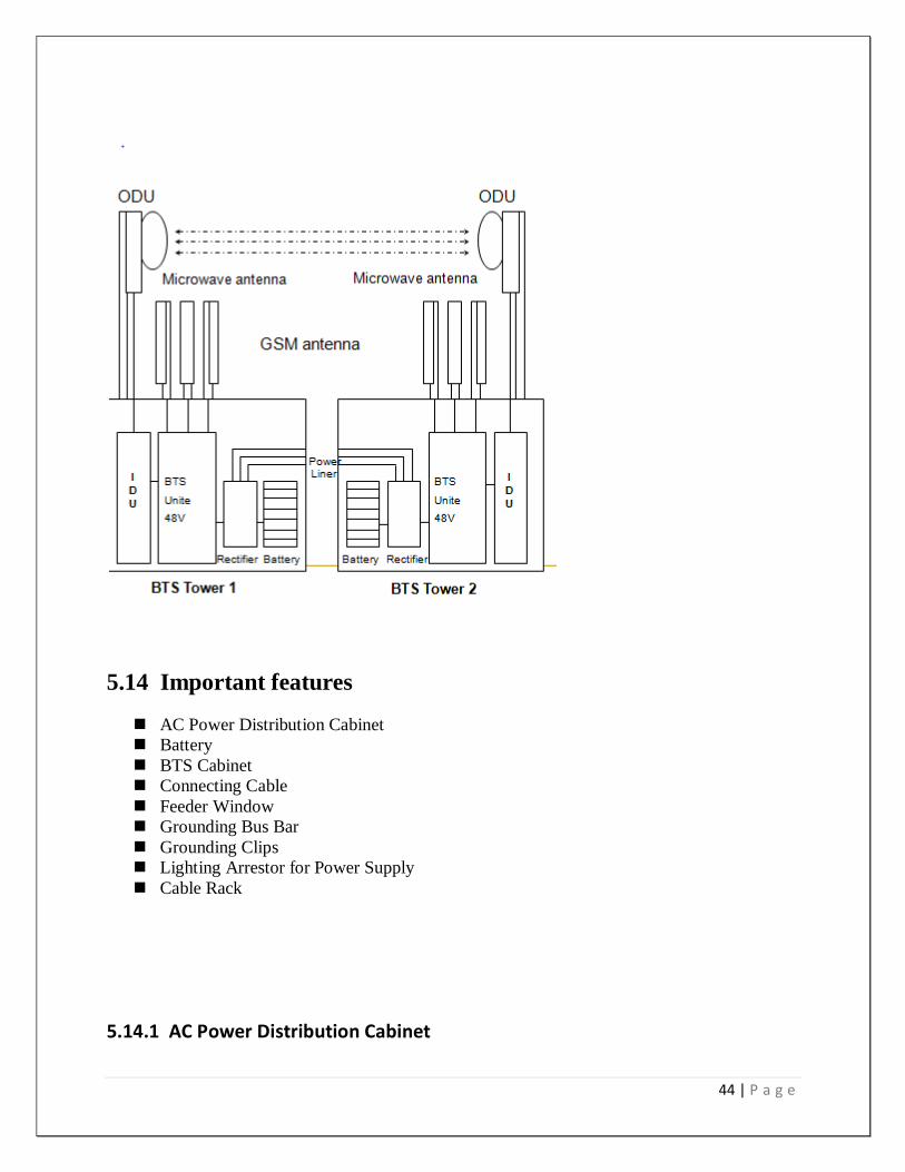
5.14 Important features 40
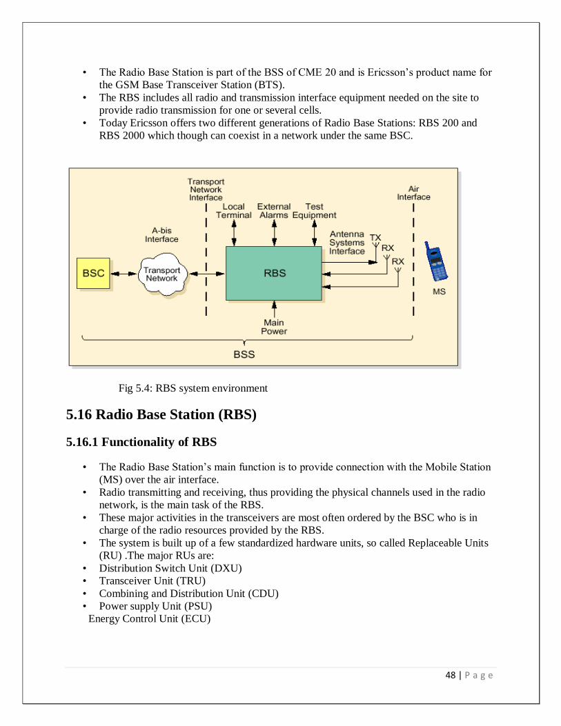
5.15 Radio Base Station (RBS) 44
5.16 Radio Base Station (RBS) 44
5.17 BSS Interfaces 45
5.18 PDS: Plesiochronous Digital Hierarchy
45
5.19 SDH: Synchronous Digital Hierarchy
45
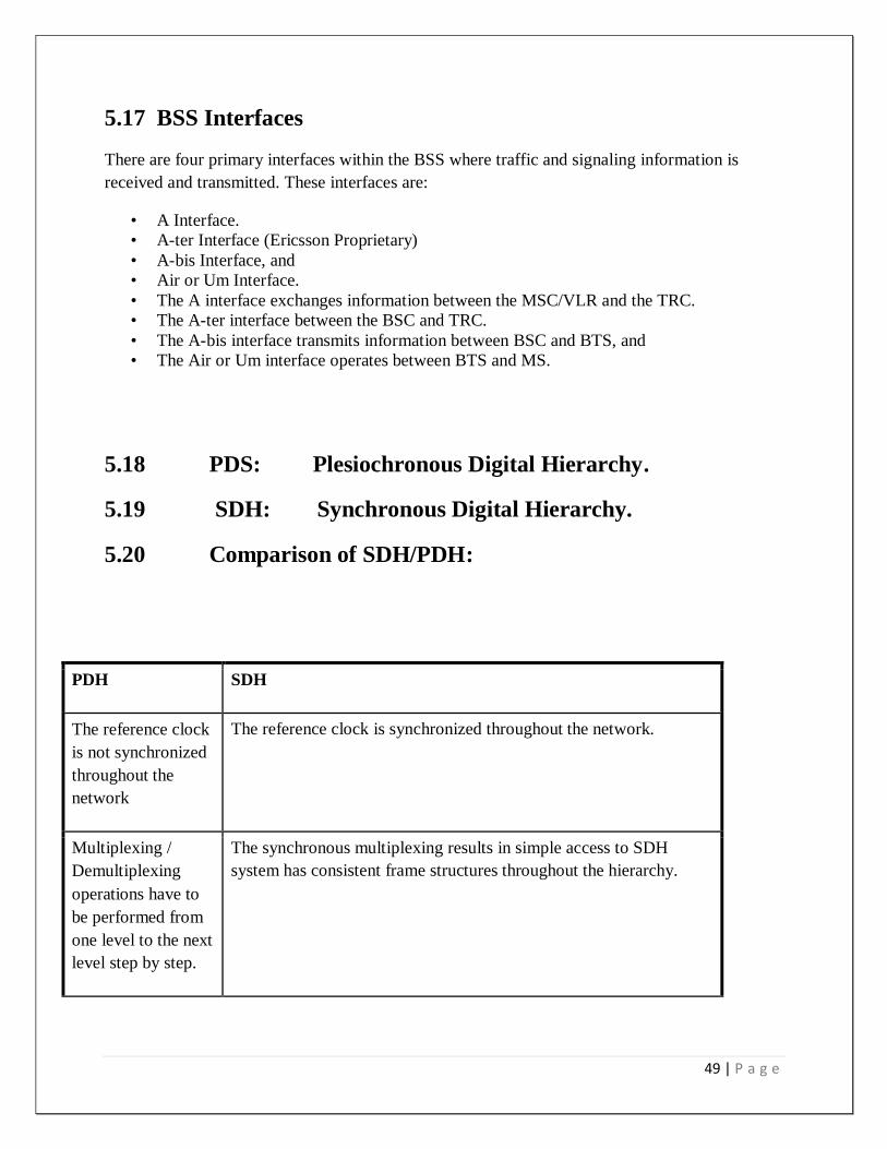
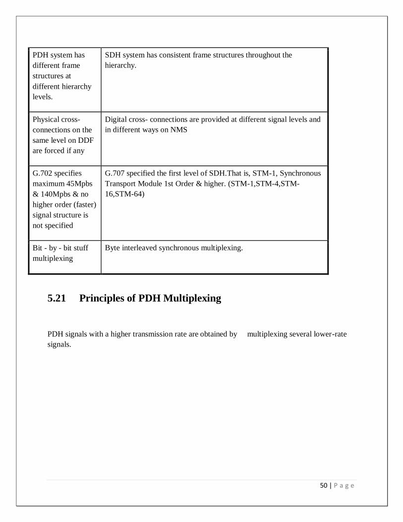
5.20 Comparison of SDH/PDH 45
5.21 Principles of PDH Multiplexing 46
CHAPTER-06 AC Power and Alarming System
47-59
6.1 Introduction 48
6.1 AC Settings 51
6.2 DC Settings 52
6.3 Rectifier Setting 53
6.4 Electrical Installation 54
6.5 Connecting Power Cables 54
3 | P a g e
6.6 Alarming system
55
6.7 I n s t a l l a t i o n o f S e n s o r 55
6.8 Smoke sensor 56
6.9 Operations: 56
6.10 Alarm Handling 57
6.11 CONCLUSION 59
Chapter-7 Reference 60
4 | P a g e
Chapter-1
5 | P a g e
Introduction
Telecommunication is the transmission of information, over significant distances, for the
purpose of communication. Today the globe is a village and telecommunication has become a
necessity to people’s life. Moreover, telecommunication has started introducing some
diversified areas with the help of its mobile network. Nowadays, people cannot think without
mobile phone. Many people depend on it for their ultimate connectivity. It has become a part
of people’s day to day life. Mobile technology is presently providing various cheap solutions in
people’s daily life. Information technology enables telecom companies to provide economic
solutions with a very cheap and easily available access, which was costly earlier and not
accessible to some extent. Using a mobile phone has become a common measure of
communication in our country. From a rickshaw puller to a higher official, everyone owns a
mobile phone. The number of mobile phone user is increasing day by day. So our country has
become an attractive market for mobile operators. Grameenphone is one of the leading mobile
operators in our country who have seen this great potential.
1.1 Origin of the Report
Internships provide an opportunity for students to link theory with practice and further serve as a
temporary labor pool for those organizations that have committed to participate in the internship
program. The internship program has following purposes:
It provides a student with a practical real world experience in the public or nonprofit sector
before entering into a job market. Such experience not only increases students‟ job prospects, but
also teaches what is expected in terms of professional behavior.
It enables a student to develop important skills which cannot be taught in the classroom.
It enables a student to compare theoretical ideas learned in the classroom within the world of work.
It permits a student to apply the technical skills learned in the classroom to real world problems.
I have prepared this report after the three months internship program in Grameenphone ltd.
This report is based on “Base Transceiver station(BTS) at Grameenphone. I have also covered
information regarding the organizational overview and what I did and learned everyday in
Grameenphone Ltd.
1.2 Objective of the Report There are two kinds of objectives of the report. They are:
Broad Objective
6 | P a g e
Specific Objective
1.2.1 Broad Objective The main objective of the report has been done to show the total working procedure of Base
Transceiver Station, fibber, etc at Grameenphone Ltd.
1.2.2 Specific Objective
The specific objectives of this internship report are:
To focus on the overview of Grameenphone Ltd
To focus on the work environment, employee behavior and have a quick glimpse of the
corporate culture of Grameenphone Ltd.
To focus on the recruitment and selection process of Grameenphone and learn how this
process takes place in reality
1.3 Scope of the Report
This study was undertaken aiming to know about the operation and maintenance of Base
Transceiver station(BTS). The scope of this study includes reviewing the technical, commercial
and customer service quality of Grameenphone and identifying tolls and techniques used by
Grameenphone to achieve remarkable performance level. Moreover, I have been worked under
system operation and system protection unit in Grameenphone and thus provide me the way to
get myself familiarized with the official environment for the first time. I had an experience by
working in the department. I had the opportunity to have close view of their activities. The area
of concentration of this report is confined in investigating different aspect of implementation
technical division
1.4 Methodology
This report was prepared in a systematic manner. My academic supervisor assigned the topic of
the report. All the information was collected from two sources:
1.4.1 Primary Sources My supervisor in Grameenphone Ltd helped me a lot in preparing the report. I interview him
face to face, he gave me all the necessary information that I needed. In addition I have also
gathered information by observing and by participating in recruitment and selection process.
7 | P a g e
1.4.2 Secondary Sources
I browsed the internet for as much information I could get. From the internet I got the
background information of the company
1.5 Limitation
Disclosing of much information is confidential. For that reason I was unable to disclose forms
that they use in the time of joining or what kind of information they keep in their personnel file.
In the following chapter I have given a glimpse of GP - their mission, vision, principles, purpose,
products, shareholders etc. This will help us to know about Grameenphone in a broader way.
8 | P a g e
Chapter-02
Background of the Organization
9 | P a g e
2.1 An Overview of the Organization
Grameenphone Ltd., the largest telecommunications service provider in Bangladesh, received its
operating license in November 1996 and started its operation from March 26, 1997, the
Independence Day of Bangladesh.Grameenphone provides services to rural and urban customers
across Bangladesh, where mobile telephony is acknowledged as a significant driver of socio-
economic development, both for individual and the nation.
Grameenphone launched a new, refreshed logo in November 2006.
The logo expresses the values Grameenphone is known for: trust,
reliability, quality and constant progress. It also signals the
company's continued focus on securing the best possible
communications services for its customers. It reflects the continuous
efforts to evolve the organization and its dynamics to serve the
customers even better in the future.Now, after 18 years of successful operations, Grameenphone
is the largest mobile phone service provider in Bangladesh, with more than 55 million
subscribers as June 2015. The Company was successfully listed on the stock exchanges in
November 2009- after completion of the largest IPO in the history of the Bangladesh capital
market.
2.2 Share Holders
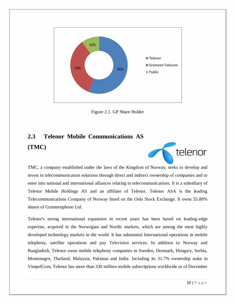
The shareholding structure comprises of mainly two sponsor Shareholders namely Telenor
Mobile Communications AS (55.80%) and Grameen Telecom (34.20%). The rest 10.00%
shareholding includes General Public & other Institutions.
10 | P a g e
Figure 2.1. GP Share Holder
2.3 Telenor Mobile Communications AS
(TMC)
TMC, a company established under the laws of the Kingdom of Norway, seeks to develop and
invest in telecommunication solutions through direct and indirect ownership of companies and to
enter into national and international alliances relating to telecommunications. It is a subsidiary of
Telenor Mobile Holdings AS and an affiliate of Telenor. Telenor ASA is the leading
Telecommunications Company of Norway listed on the Oslo Stock Exchange. It owns 55.80%
shares of Grameenphone Ltd.
Telenor's strong international expansion in recent years has been based on leading-edge
expertise, acquired in the Norwegian and Nordic markets, which are among the most highly
developed technology markets in the world. It has substantial International operations in mobile
telephony, satellite operations and pay Television services. In addition to Norway and
Bangladesh, Telenor owns mobile telephony companies in Sweden, Denmark, Hungary, Serbia,
Montenegro, Thailand, Malaysia, Pakistan and India. Including its 31.7% ownership stake in
VimpelCom, Telenor has more than 330 million mobile subscriptions worldwide as of December
56%34%
10%
Telenor
Grameen Telecom
Public
11 | P a g e
31, 2011.Telenor uses the expertise it has gained in its home and international markets for the
development of emerging markets like Bangladesh.As part of the conversion of Grameenphone
from a private limited to a public limited company, Telenor Mobile Communications AS
transferred 10 shares each on May 31, 2007 to its three (3) affiliate organizations namely Nye
Telenor Mobile Communications II AS, Norway; Telenor Asia Pte. Ltd., Singapore; and Nye
Telenor Mobile Communications III AS, Norway.
2.4 Grameen Telecom (GTC)
Grameen Telecom, which owns 34.20% of the shares of
Grameenphone, is a not-for-profit company in Bangladesh
established by Professor Muhammad Yunus, winner of the
Nobel Peace Prize 2006.GTC‟s mandate is to provide easy access to GSM cellular services in
rural Bangladesh and create new opportunities for income generation through self-employment
by providing villagers, mostly to the poor rural women with access to modern information and
communication-based technologies.Grameen Telecom, with its field network, administers the
Village Phone Program, through which Grameenphone provides its services to the fast growing
rural customers, Grameen Telecom trains the operators and handles all service-related
issues.GTC has been acclaimed for the innovative Village Phone Program. GTC & its Chairman
Nobel Peace prize laureate Professor Muhammad Yunus have received several awards which
include; First ITU World information Society Award in 2005; PetersburgPrize for Use of the IT
to improve Poor People‟s Lives” in 2004; GSM Association Award for “GSM in Community
Service” in 2000.As part of the conversion of Grameenphone from a private limited to a public
limited company, Grameen Telecom transferred share each on May 31, 2007 to its two affiliate
organizations namely GrameenKalyan and Grameen Shakti.
2.4 Grameen Telecom
Grameenphone‟s vision is “We’re here to help.” That means Grameenphone Ltd. is always
there to help the customers get the full assistance of communications services in their daily lives.
They want to make it simple for the customers to get what and when they want it.
12 | P a g e
2.5 Company Mission
The mission of Grameenphone Ltd is to deliver reliable, widespread, convenient mobile and cost
effective telephone services to the people in Bangladesh irrespective of where they live .They are
providing a total communication solution to its customers. To do this, the service advance of
Grameenphone has extensively developed over the last few years. Grameenphone
subscribers now enjoy all the modern data communication and content services. Mobile office,
internet access, MMS and modern music and download services are available through the
nationwide EDGE enabled network
2.6 Company’s Objectives
Grameenphone (GP) has been established to provide high-quality GSM cellular service at
affordable prices. Grameenphone has a dual purpose: To receive an economic return on its
investment
To contribute to the economic development of Bangladesh where
telecommunications can play a critical role The Company has developed its strategies so that it
earns healthy returns for its share holdersand at the same time, contributes to genuine
development of the country. This is why Grameenphone, in collaboration with Grameen Bank
and Grameen Telecom, is aiming to place one phone in each village to contribute significantly to
the economic benefit of the poor. It is on the way to get a total uprising in the telecommunication
field.
2.7 Company’s strategy
Grameenphone Limited's strategy was to effectively become the second national operator in
Bangladesh. Instead of focusing on a high-end, niche market; it pursued a low tariff strategy
designed to compete directly with BTTB
13 | P a g e
2.8 Company’s Value
2.9.1 Make it Easy
Grameenphone believes that they are sensible. Everything they create is easy to appreciate and
use as they never fail to remember that they are trying to make their customers' lives easier.
2.9.2 Be Inspiring
Grameenphone believes that they are imaginative. They convey energy and thoughts to their
network. Grameenphone wants to be a collaborator in the progress of our society. They are
passionate about our business, customers and country.
2.9.3 Keep Promise
Everything Grameenphone set out to do should work. If it does not, they are there to putting
right. They are about delivery, not over promising - actions not words.
2.9.4 Be Respectful
Grameenphone shows acknowledgement and admiration the local culture. They are courteous
and professional in regard to all interactions, both internally and externally. They are open,
helpful and friendly.
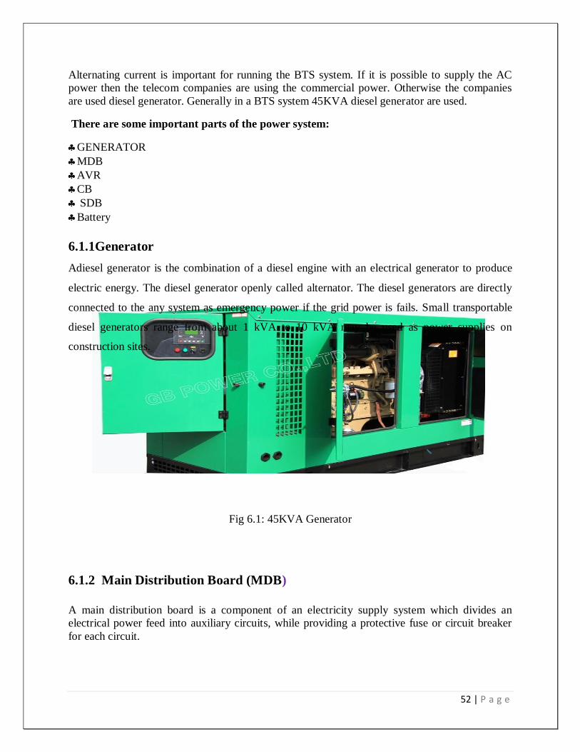
6.
14 | P a g e
Chapter -3
Microwave link PNMS (Paso link Network
Management System)
15 | P a g e
3.1 System description
This chapter gives the detailed description of the equipment features and subsystems that have
not been given in the previous part. Information given in the following is:
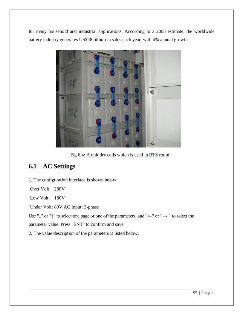
for many household and industrial applications. According to a 2005 estimate, the worldwide
battery industry generates US$48 billion in sales each year, with 6% annual growth.
Fig 6.4: A unit dry cells which is used in BTS room
6.1 AC Settings
1. The configuration interface is shown below:
Over Volt 280V
Low Volt: 180V
Under Volt: 80V AC Input: 3-phase
Use "↓" or "↑" to select one page or one of the parameters, and "←" or "→." to select the
parameter value. Press "ENT" to confirm and save.
2. The value description of the parameters is listed below:
56 | P a g e
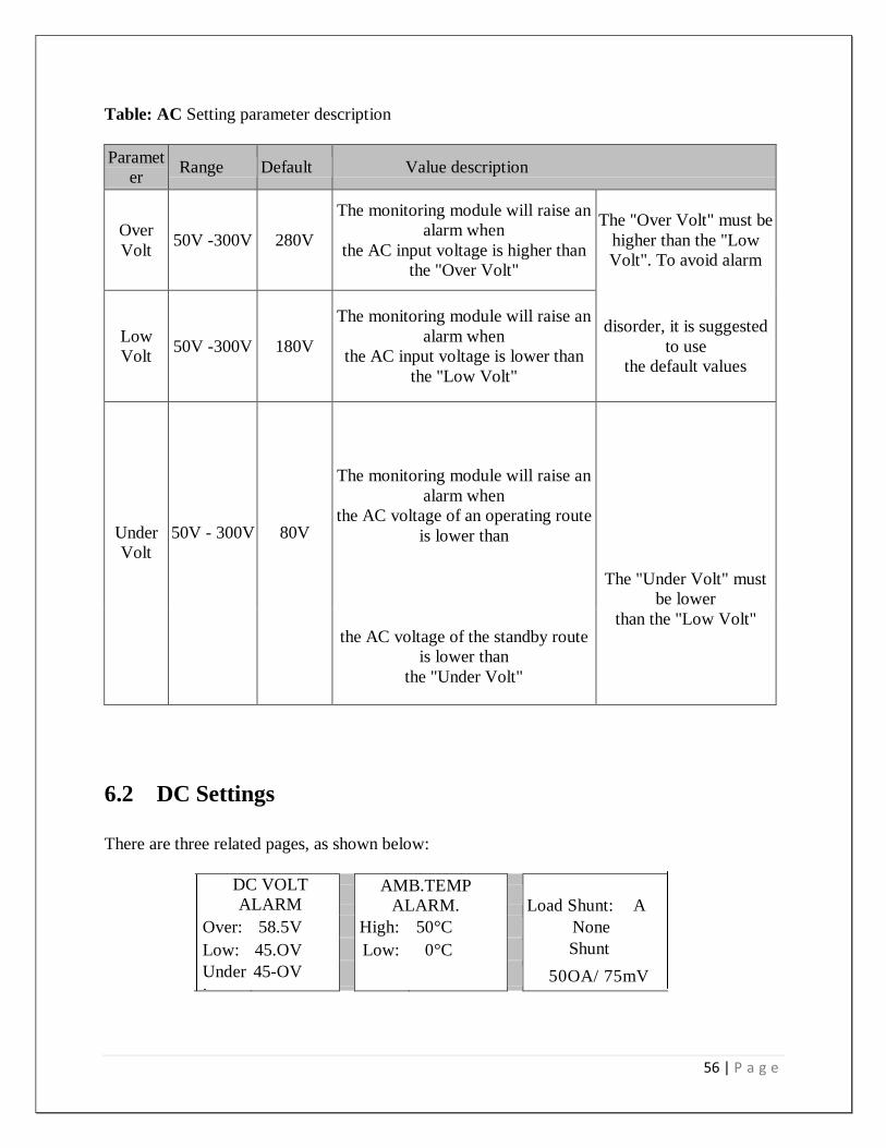
Table: AC Setting parameter description
Paramet
er Range Default Value description
Over
Volt 50V -300V 280V
The monitoring module will raise an
alarm when
the AC input voltage is higher than
the "Over Volt"
The "Over Volt" must be
higher than the "Low
Volt". To avoid alarm
Low
Volt 50V -300V 180V
The monitoring module will raise an
alarm when
the AC input voltage is lower than
the "Low Volt"
disorder, it is suggested
to use
the default values
Under
Volt
50V - 300V
80V
The monitoring module will raise an
alarm when
the AC voltage of an operating route
is lower than
The "Under Volt" must
be lower
the AC voltage of the standby route
is lower than
the "Under Volt"
than the "Low Volt"
6.2 DC Settings
There are three related pages, as shown below:
DC VOLT
ALARM
AMB.TEMP
ALARM.
Load Shunt: A
Over: 58.5V High: 50°C None
Low: 45.OV Low: 0°C Shunt
Coeff: Under
:
45-OV 50OA/ 75mV
57 | P a g e
Use "↑" or "↑" to select one page or one of the parameters, and " t " or to select the
parameter value. Press "ENT" to confirm and save.
6.3 Rectifier Setting
1. There are three related pages, as shown below:
Use "↓" or "↑" to select one page or one of the parameters, and "←" or →" to select the
parameter value. Press "ENT" to confirm and save.
2. The value description of the parameters is listed below:
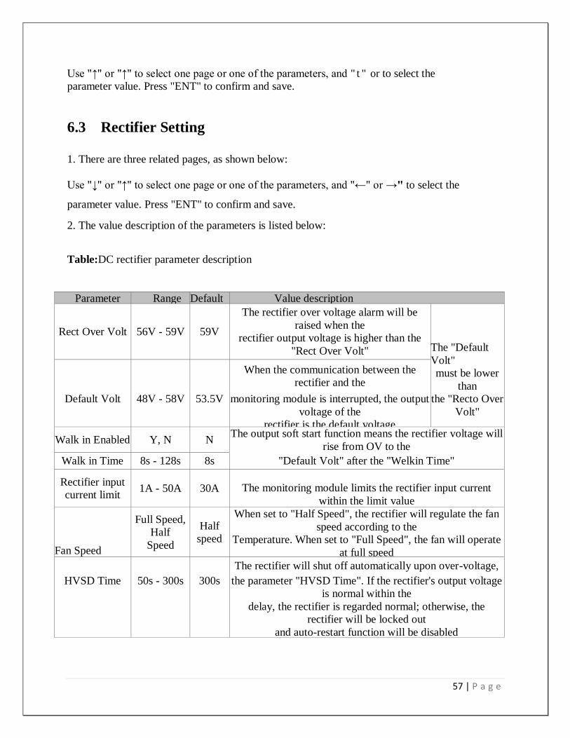
Table:DC rectifier parameter description
Parameter Range Default Value description
Rect Over Volt 56V - 59V 59V
The rectifier over voltage alarm will be
raised when the
rectifier output voltage is higher than the
"Rect Over Volt" The "Default
Volt"
must be lower
than
When the communication between the
rectifier and the
Default Volt 48V - 58V 53.5V monitoring module is interrupted, the output
voltage of the
rectifier is the default voltage
the "Recto Over
Volt"
Walk in Enabled Y, N N The output soft start function means the rectifier voltage will
rise from OV to the
Walk in Time 8s - 128s 8s "Default Volt" after the "Welkin Time"
Rectifier input
current limit 1A - 50A 30A The monitoring module limits the rectifier input current
within the limit value
Fan Speed
Full Speed,
Half
Speed
Half
speed
When set to "Half Speed", the rectifier will regulate the fan
speed according to the
Temperature. When set to "Full Speed", the fan will operate
at full speed
The rectifier will shut off automatically upon over-voltage,
HVSD Time 50s - 300s 300s the parameter "HVSD Time". If the rectifier's output voltage
is normal within the
delay, the rectifier is regarded normal; otherwise, the
rectifier will be locked out
and auto-restart function will be disabled
58 | P a g e
6.4 Electrical Installation
6.5.1 Connecting Power Cables
6.5.2 Danger:
Switch off all MCBs and pull out all fuses before the electrical connection.
Only the qualified personnel can do the mains cable connection.
6.5.3 Connecting grounding cable Connect one end of the grounding cable to the grounding bus bar of the machine room, and
the other end to thegrounding bus bar of the system.
6.5.4 Connecting AC cables
Take PS48300/1800-X1 system for example. Feed the AC cables into the cabinet from the top.
Connect them to theinput MCB.
6.5.5 Connection of load cables Connect the negative cable of the load to the upper terminal of "negative DC output MCB". Connect the positive cableof the load to the "positive DC output bus bar", as shown in Figure the batteries may have dangerous current. Before connecting the battery cables, the corresponding battery input muss or the battery cell connector must be disconnected to avoid live state of the power system after installation. 6.5.6 Connecting Signal Cables All the signal cables are connected to the signal transfer board. The position of the signal transfer board is shown in The temperature sensor (cable) is an optional accessory.
Operating voltage: 5V
Measurement range: -5°C - 100°C
Measurement precision: ± 2°C
Installation procedures:
Connect the 3-core plug of the temperature sensor cable to the J10 or J11 socket on board Put the temperature probe in the battery room where best represents the ambient temperature of the battery. Do not connect it to other heat-generating equipment
6.5.7 Safety Regulation Certain components in this power system have hazardous voltage and current. Always follow the
instructions below:
1. Only the adequately trained personnel with satisfactory knowledge of the
power system can carry out the installation. The most recent revision of these
safety rules and local safety rules in force shall be adhered to during the
installation.
2. All external circuits that are below 48V and connected to the power
systemmust comply with the requirements of SELV as defined in IEC 60950
59 | P a g e
3. Make sure that the power (mains and battery) to the system is cut off before
any operations can be carried out within the system cabinet.
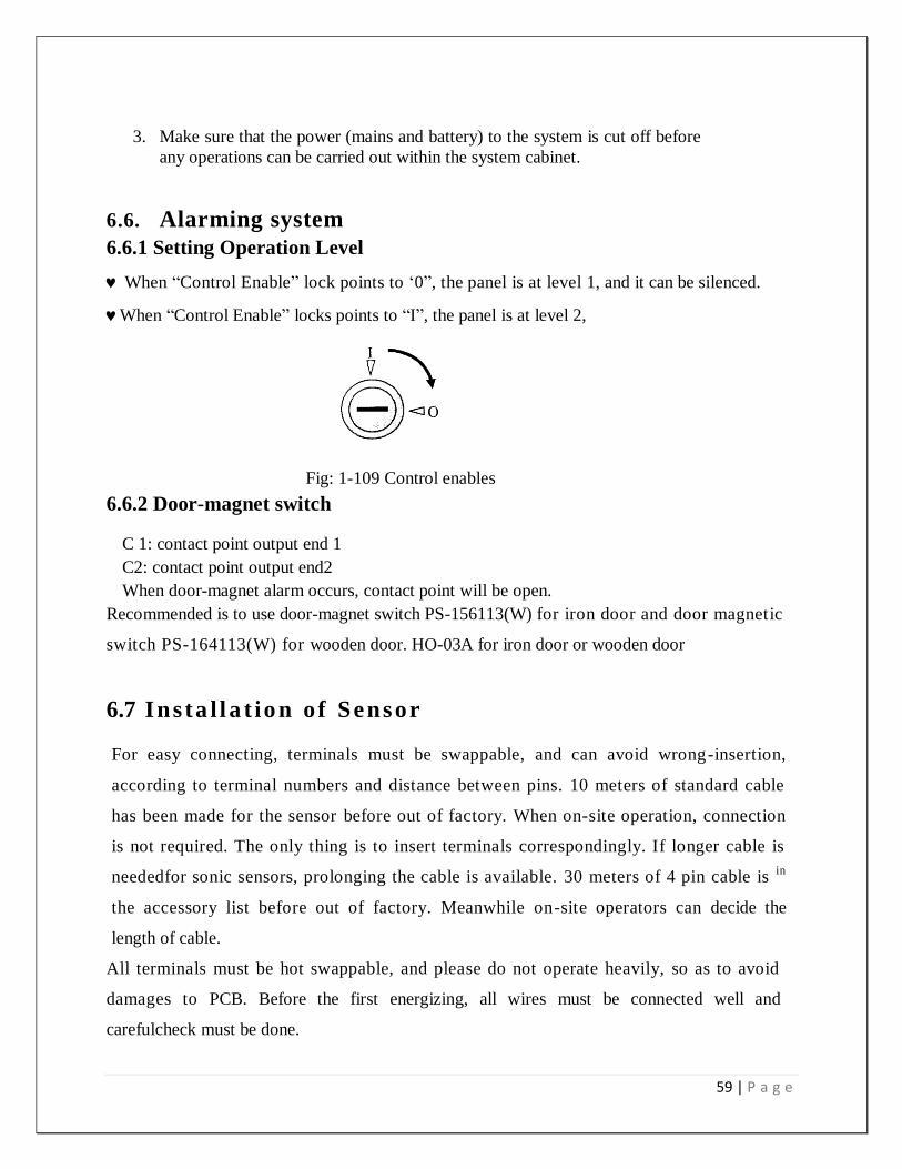
6.6. Alarming system
6.6.1 Setting Operation Level
When “Control Enable” lock points to „0”, the panel is at level 1, and it can be silenced.
When “Control Enable” locks points to “I”, the panel is at level 2,
Fig: 1-109 Control enables
6.6.2 Door-magnet switch
C 1: contact point output end 1
C2: contact point output end2
When door-magnet alarm occurs, contact point will be open.
Recommended is to use door-magnet switch PS-156113(W) for iron door and door magnetic
switch PS-164113(W) for wooden door. HO-03A for iron door or wooden door
6.7 Ins ta l l a t io n of Sensor
For easy connecting, terminals must be swappable, and can avoid wrong-insertion,
according to terminal numbers and distance between pins. 10 meters of standard cable
has been made for the sensor before out of factory. When on-site operation, connection
is not required. The only thing is to insert terminals correspondingly. If longer cable is
neededfor sonic sensors, prolonging the cable is available. 30 meters of 4 pin cable is in
the accessory list before out of factory. Meanwhile on-site operators can decide the
length of cable.
All terminals must be hot swappable, and please do not operate heavily, so as to avoid
damages to PCB. Before the first energizing, all wires must be connected well and
carefulcheck must be done.
60 | P a g e
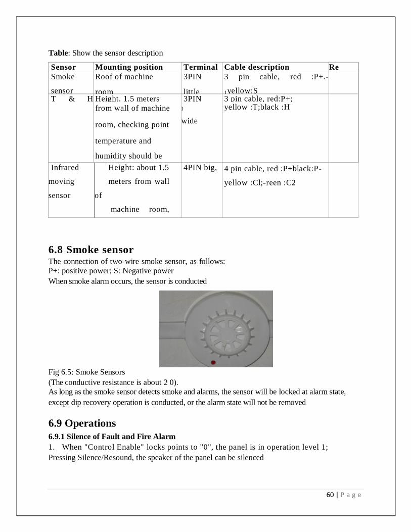
Table: Show the sensor description
Sensor Mounting position Terminal Cable description Re
m
ar
k
Smoke
sensor
Roof of machine
room
3PIN
little
3 pin cable, red :P+.-
1yellow:S
T & H
sensor
Height. 1.5 meters 3PIN 3 pin cable, red:P+;
from wall of machine
room, checking point
temperature and
humidity should be
Representative.
I
wide
yellow :T;black :H
Infrared
moving
sensor
Height: about 1.5
meters from wall
of
machine room,
can
detect the whole
Machine room.
4PIN big, 4 pin cable, red :P+black:P-
yellow :Cl;-reen :C2
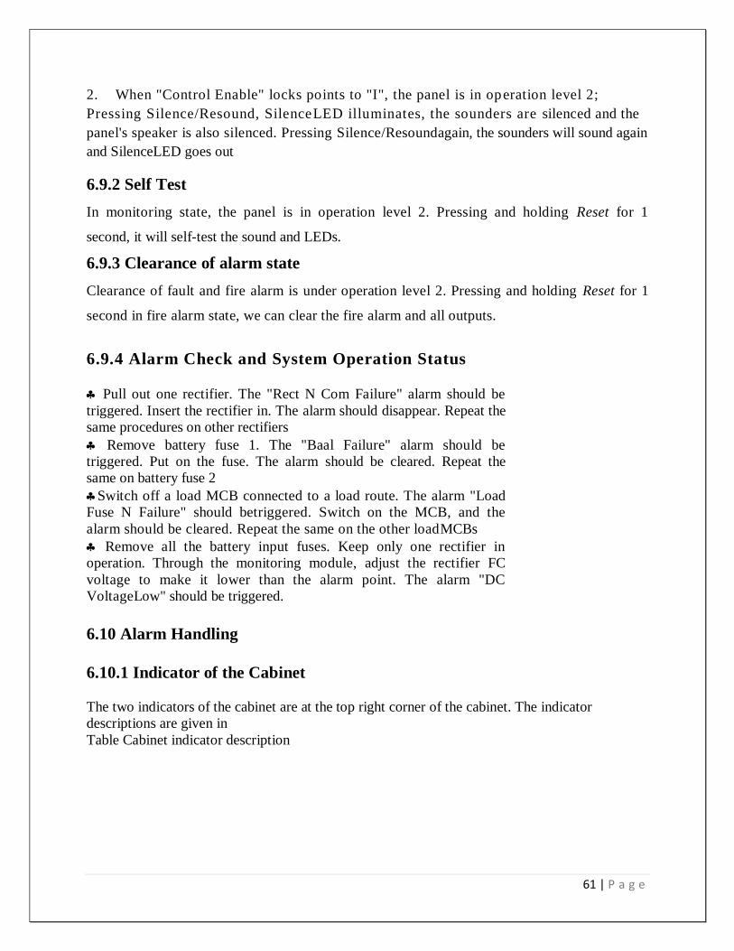
6.8 Smoke sensor The connection of two-wire smoke sensor, as follows:
P+: positive power; S: Negative power
When smoke alarm occurs, the sensor is conducted
Fig 6.5: Smoke Sensors
(The conductive resistance is about 2 0).
As long as the smoke sensor detects smoke and alarms, the sensor will be locked at alarm state,
except dip recovery operation is conducted, or the alarm state will not be removed
6.9 Operations
6.9.1 Silence of Fault and Fire Alarm
1. When "Control Enable" locks points to "0", the panel is in operation level 1;
Pressing Silence/Resound, the speaker of the panel can be silenced
61 | P a g e
2. When "Control Enable" locks points to "I", the panel is in operation level 2;
Pressing Silence/Resound, SilenceLED illuminates, the sounders are silenced and the
panel's speaker is also silenced. Pressing Silence/Resoundagain, the sounders will sound again
and SilenceLED goes out
6.9.2 Self Test
In monitoring state, the panel is in operation level 2. Pressing and holding Reset for 1
second, it will self-test the sound and LEDs.
6.9.3 Clearance of alarm state
Clearance of fault and fire alarm is under operation level 2. Pressing and holding Reset for 1
second in fire alarm state, we can clear the fire alarm and all outputs.
6.9.4 Alarm Check and System Operation Status
Pull out one rectifier. The "Rect N Com Failure" alarm should be
triggered. Insert the rectifier in. The alarm should disappear. Repeat the
same procedures on other rectifiers
Remove battery fuse 1. The "Baal Failure" alarm should be
triggered. Put on the fuse. The alarm should be cleared. Repeat the
same on battery fuse 2
Switch off a load MCB connected to a load route. The alarm "Load
Fuse N Failure" should betriggered. Switch on the MCB, and the
alarm should be cleared. Repeat the same on the other loadMCBs
Remove all the battery input fuses. Keep only one rectifier in
operation. Through the monitoring module, adjust the rectifier FC
voltage to make it lower than the alarm point. The alarm "DC
VoltageLow" should be triggered.
6.10 Alarm Handling
6.10.1 Indicator of the Cabinet
The two indicators of the cabinet are at the top right corner of the cabinet. The indicator
descriptions are given in
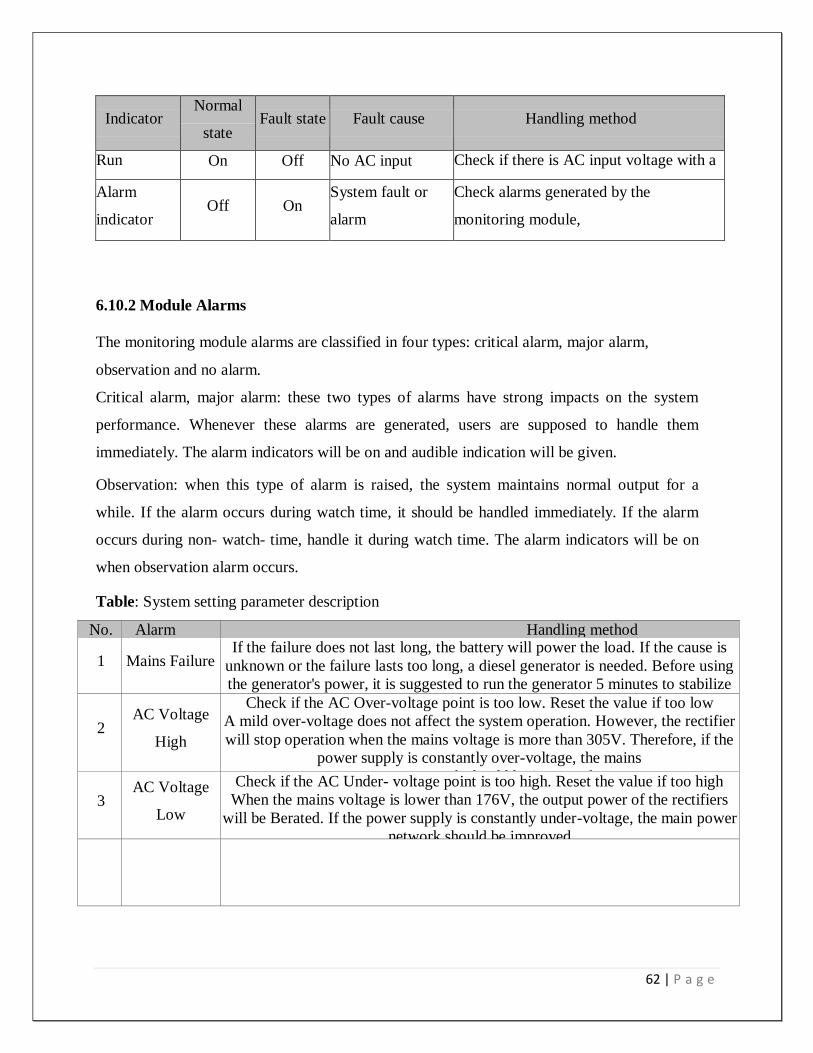
Table Cabinet indicator description
62 | P a g e
Indicator Normal
state Fault state Fault cause Handling method
Run
indicator
On Off No AC input Check if there is AC input voltage with a
multimeter Alarm
indicator Off On
System fault or
alarm
Check alarms generated by the
monitoring module,
6.10.2 Module Alarms
The monitoring module alarms are classified in four types: critical alarm, major alarm,
observation and no alarm.
Critical alarm, major alarm: these two types of alarms have strong impacts on the system
performance. Whenever these alarms are generated, users are supposed to handle them
immediately. The alarm indicators will be on and audible indication will be given.
Observation: when this type of alarm is raised, the system maintains normal output for a
while. If the alarm occurs during watch time, it should be handled immediately. If the alarm
occurs during non- watch- time, handle it during watch time. The alarm indicators will be on
when observation alarm occurs.
Table: System setting parameter description
No. Alarm Handling method
1 Mains Failure If the failure does not last long, the battery will power the load. If the cause is
unknown or the failure lasts too long, a diesel generator is needed. Before using
the generator's power, it is suggested to run the generator 5 minutes to stabilize
the power output
2 AC Voltage
High
Check if the AC Over-voltage point is too low. Reset the value if too low
A mild over-voltage does not affect the system operation. However, the rectifier
will stop operation when the mains voltage is more than 305V. Therefore, if the
power supply is constantly over-voltage, the mains
power network should be improved
3 AC Voltage
Low
Check if the AC Under- voltage point is too high. Reset the value if too high
When the mains voltage is lower than 176V, the output power of the rectifiers
will be Berated. If the power supply is constantly under-voltage, the main power
network should be improved
63 | P a g e
6.11 CONCLUSION
From our attachment program we have advanced knowledge on 3 Generation GSM technologies.
In Europe already 3.5 generation technology has been launched, in Bangladesh various mobile
operators are trying to launch 3.5G. We are very much indebted to grameenphone for this
attachment program. We wish more success of grameenphone ltd.
64 | P a g e
CHAPTER-07
References
65 | P a g e
www.grameenphone.com:
http://www.grameenphone.com
ARRL UHF/Microwave Experimenters Manual (American Radio Relay).
Freeman, R.L. Radio System Design for Telecommunication. 1987.
Hollemans , W., and A. Veschoor. Performance Study of Wave LAN and Arial Radio LANs:
Proceeding of the 5th IEEE Symposium on Personal, Indoor.
Lee, W.C.Y. Mobile Communication Design Fundamentals. 2nd
ed. Wiley and Sons, 1993.
Reudink, D. Advance Concept and Technologies for Communication Satellite: In Advance
Digital Communication. New York: Prentice Hall, 1987.