18
Strut Systems SS-18 Strut systems
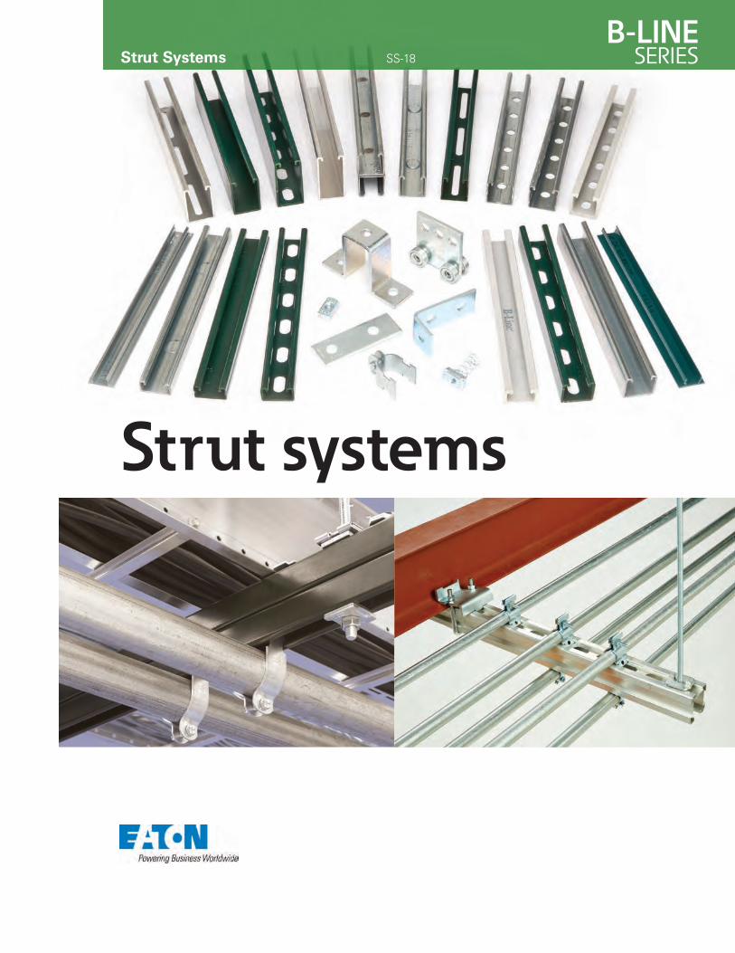
Strut Systems SS-18
Strut systems
B-Line series strut systemsEaton
Table of contents
NOTICEEaton reserves the right to change the specifications, materials, equipment, prices or the availability of products at any time without prior notice. While every effort has been made to assure the accuracy of information contained in this catalog at the time of publication, we are not responsible for inaccuracies resulting from undetected errors or omissions.
Eaton is a leading manufacturer and fabricator of steel and aluminum B-Line series products which are used in support of equipment for industrial, commercial, utility, and OEM installations. We are proud of the exacting standards of research, design, engineering, and manufacturing that go into each and every product that comprise our strut product line. Our customers have access to one of the most complete support systems offered in the industry, including metal framing, cable tray, pipe hangers, slotted angle, and fasteners.
Many of our products are listed by the Underwriter’s Laboratories, Inc. All of our strut system products are manufactured to meet or exceed Metal Framing Manufacturers Association (MFMA) and other industry standards set for their design and manufacture.
Metal Framing Manufacturers Association
1B-Line series strut systems Eaton
CoSPEC™ specifier center is designed to help you easily SELECT, VIEW and DOWNLOAD Eaton’sB-Line Series product design content in any one of nearly one hundred non-proprietary and proprietary CAD, BIM, PDMS, and graphics formats, which helps speed the integration of the content into your design project.
Features • Easy integration and configuration • Comprehensive library of 2D drawings and 3D models for CAD, BIM, PDMS, SP3D, and graphics output • Up-to-date software versions and product data information • Submittals and specification sheets in PDF format • Proprietary file format outputs are native to the chosen software
Nearly a Hundred Download Options • Aveva PDMS and Intergraph SmartPlant SP3D (on select products) content • Autodesk Revit output available • Proprietary formats from AutoCAD to SolidWorks to Catia • Non-proprietary formats like DXF and STEP, and more • Graphics files in a number of formats including EPS
Channel and CombinationsIntroduction .................................................................................................................................................................... 4 - 5
Technical Data
Materials and Finishes ......................................................................................................................................... 6 - 8 Welding and Corrosion ...................................................................................................................................... 9 - 11 Design of Strut Systems and Recommended Specification ........................................... 12 - 15
4Dimension™ Strut
Discontinued product . . . . . . . . . . . . . . . . . . . . . . . . . . . . . . . . . . . . . . . . . . . . . . . . . . . . . . . . . . 16 - 47
Channel and Combinations Information and Specifications and Selection Chart . . . . . . . . . . . . . . . . . . . . . . . . . . . . . 48 - 49 B11 Channel . . . . . . . . . . . . . . . . . . . . . . . . . . . . . . . . . . . . . . . . . . . . . . . . . . . . . . . . . . . . . . . . . . . 50 - 51 B12 Channel . . . . . . . . . . . . . . . . . . . . . . . . . . . . . . . . . . . . . . . . . . . . . . . . . . . . . . . . . . . . . . . . . . . 52 - 53 B22, B24, Channels . . . . . . . . . . . . . . . . . . . . . . . . . . . . . . . . . . . . . . . . . . . . . . . . . . . . . . . . . . . . 54 - 61 B32 Channel . . . . . . . . . . . . . . . . . . . . . . . . . . . . . . . . . . . . . . . . . . . . . . . . . . . . . . . . . . . . . . . . . . . 62 - 63 B42 Channel . . . . . . . . . . . . . . . . . . . . . . . . . . . . . . . . . . . . . . . . . . . . . . . . . . . . . . . . . . . . . . . . . . . 64 - 65 B52, B54, Channels . . . . . . . . . . . . . . . . . . . . . . . . . . . . . . . . . . . . . . . . . . . . . . . . . . . . . . . . . . . . 66 - 71 DISCONTINUED Telescoping Channel . . . . . . . . . . . . . . . . . . . . . . . . . . . . . . . . . . . . . . . . . 72 - 73 Channel Hole Patterns . . . . . . . . . . . . . . . . . . . . . . . . . . . . . . . . . . . . . . . . . . . . . . . . . . . . . . . . . 74 - 76 Channel Closure Strips . . . . . . . . . . . . . . . . . . . . . . . . . . . . . . . . . . . . . . . . . . . . . . . . . . . . . . . . . . . . . . 77 Hydraulic Cutter . . . . . . . . . . . . . . . . . . . . . . . . . . . . . . . . . . . . . . . . . . . . . . . . . . . . . . . . . . . . . . . . . . . 77b
Channel Nuts and Hardware
Information and Specifications . . . . . . . . . . . . . . . . . . . . . . . . . . . . . . . . . . . . . . . . . . . . . . . . . . . . . . 78 Channel Nuts Selection Charts . . . . . . . . . . . . . . . . . . . . . . . . . . . . . . . . . . . . . . . . . . . . . . . . . 79 - 83 Channel Nuts Slip and Pull-out Load Charts . . . . . . . . . . . . . . . . . . . . . . . . . . . . . . . . . . . . 84 - 85 Other Hardware . . . . . . . . . . . . . . . . . . . . . . . . . . . . . . . . . . . . . . . . . . . . . . . . . . . . . . . . . . . . . . . 86 - 92 KwikWire™ and Accessories . . . . . . . . . . . . . . . . . . . . . . . . . . . . . . . . . . . . . . . . . . . . . . . . . . . 93 - 104
Strut Fittings
Information and Specifications . . . . . . . . . . . . . . . . . . . . . . . . . . . . . . . . . . . . . . . . . . . . . . . . . . . . . 106 Flat Plate Fittings . . . . . . . . . . . . . . . . . . . . . . . . . . . . . . . . . . . . . . . . . . . . . . . . . . . . . . . . . . . . 107 - 109 90° Angle Fittings . . . . . . . . . . . . . . . . . . . . . . . . . . . . . . . . . . . . . . . . . . . . . . . . . . . . . . . . . . . . 110 - 115 Angular Fittings . . . . . . . . . . . . . . . . . . . . . . . . . . . . . . . . . . . . . . . . . . . . . . . . . . . . . . . . . . . . . . 116 - 118 Miscellaneous Seismic Fittings . . . . . . . . . . . . . . . . . . . . . . . . . . . . . . . . . . . . . . . . . . . . . . . 119 - 125 Braces . . . . . . . . . . . . . . . . . . . . . . . . . . . . . . . . . . . . . . . . . . . . . . . . . . . . . . . . . . . . . . . . . . . . . . . . . . . . . 126 Clevis Fittings . . . . . . . . . . . . . . . . . . . . . . . . . . . . . . . . . . . . . . . . . . . . . . . . . . . . . . . . . . . . . . . . . . . . . . 127 U-Fittings . . . . . . . . . . . . . . . . . . . . . . . . . . . . . . . . . . . . . . . . . . . . . . . . . . . . . . . . . . . . . . . . . . . . 128 - 131 Z-Fittings . . . . . . . . . . . . . . . . . . . . . . . . . . . . . . . . . . . . . . . . . . . . . . . . . . . . . . . . . . . . . . . . . . . . 132 - 134 Wing Fittings . . . . . . . . . . . . . . . . . . . . . . . . . . . . . . . . . . . . . . . . . . . . . . . . . . . . . . . . . . . . . . . . 134 - 137 Post Bases . . . . . . . . . . . . . . . . . . . . . . . . . . . . . . . . . . . . . . . . . . . . . . . . . . . . . . . . . . . . . . . . . . 137 - 139 Brackets . . . . . . . . . . . . . . . . . . . . . . . . . . . . . . . . . . . . . . . . . . . . . . . . . . . . . . . . . . . . . . . . . . . . . 139 - 147 Miscellaneous Fittings . . . . . . . . . . . . . . . . . . . . . . . . . . . . . . . . . . . . . . . . . . . . . . . . . . . . . . . 148 - 153
Beam Clamps and Accessories
Information and Specifications . . . . . . . . . . . . . . . . . . . . . . . . . . . . . . . . . . . . . . . . . . . . . . . . . . . . . 154 Beam Clamps and Accessories . . . . . . . . . . . . . . . . . . . . . . . . . . . . . . . . . . . . . . . . . . . . . . 155 - 167
Pipe/Conduit Clamps and Hangers
Information and Specifications . . . . . . . . . . . . . . . . . . . . . . . . . . . . . . . . . . . . . . . . . . . . . . . . . . . . . 168 Pipe Clamps and Vibra Clamps . . . . . . . . . . . . . . . . . . . . . . . . . . . . . . . . . . . . . . . . . . . . . . . 169 - 179 Armafix™ Clamps and Accessories . . . . . . . . . . . . . . . . . . . . . . . . . . . . . . . . . . . . . . . . . . . . . . . . . 180 Vibra Cushions . . . . . . . . . . . . . . . . . . . . . . . . . . . . . . . . . . . . . . . . . . . . . . . . . . . . . . . . . . . . . . . . . . . . . 181 Pipe Clamps, Hangers, and Brackets . . . . . . . . . . . . . . . . . . . . . . . . . . . . . . . . . . . . . . . . . 182 - 189 Pipe Block and Rollers . . . . . . . . . . . . . . . . . . . . . . . . . . . . . . . . . . . . . . . . . . . . . . . . . . . . . . . 190 - 195
Table of contents
B-Line series strut systems2Eaton
Table of contents
For additional information on Tolco™ brand part numbers beginning with Fig., visit Eaton.com/TOLCO.
DURA-BLOK™ Rooftop Supports
Information and Specifications . . . . . . . . . . . . . . . . . . . . . . . . . . . . . . . . . . . . . . . . . . . . . . . . . . . . . 196 Base Support - With and Without Channel . . . . . . . . . . . . . . . . . . . . . . . . . . . . . . . . . . . . . . . . . 197 Base Support - Pipe/Tubing Riser . . . . . . . . . . . . . . . . . . . . . . . . . . . . . . . . . . . . . . . . . . . . . . . . . . 198 Base Support Riser - Channel and Pipe Roller . . . . . . . . . . . . . . . . . . . . . . . . . . . . . . . . . . . . . . 199 Base Support - ‘H’ Stand . . . . . . . . . . . . . . . . . . . . . . . . . . . . . . . . . . . . . . . . . . . . . . . . . . . . . 200 - 201 Base Support - Pipe Roller . . . . . . . . . . . . . . . . . . . . . . . . . . . . . . . . . . . . . . . . . . . . . . . . . . . . . . . . . 202 Application and Roof-Top Walkway Photos . . . . . . . . . . . . . . . . . . . . . . . . . . . . . . . . . . . 203 - 205
Electrical Accessories
Information and Specifications . . . . . . . . . . . . . . . . . . . . . . . . . . . . . . . . . . . . . . . . . . . . . . . . . . . . . . 206 Selection Chart . . . . . . . . . . . . . . . . . . . . . . . . . . . . . . . . . . . . . . . . . . . . . . . . . . . . . . . . . . . . . . . . . . . . 207 Fluorescent Fixture Hangers . . . . . . . . . . . . . . . . . . . . . . . . . . . . . . . . . . . . . . . . . . . . . . . . . 208 - 210 Electrical Accessories . . . . . . . . . . . . . . . . . . . . . . . . . . . . . . . . . . . . . . . . . . . . . . . . . . . . . . . . 211 - 212 Junction Boxes and Strut Joiners . . . . . . . . . . . . . . . . . . . . . . . . . . . . . . . . . . . . . . . . . . . . 213 - 215 Electrical Hardware and Porcelain Saddles . . . . . . . . . . . . . . . . . . . . . . . . . . . . . . . . . . . . . . . . . 216 Insulclamp™ Cable Clamps . . . . . . . . . . . . . . . . . . . . . . . . . . . . . . . . . . . . . . . . . . . . . . . . . . . . . . . . . 217
Aluminum and Stainless Steel Materials
Information and Specifications . . . . . . . . . . . . . . . . . . . . . . . . . . . . . . . . . . . . . . . . . . . . . . . . . . . . . . 218 Aluminum . . . . . . . . . . . . . . . . . . . . . . . . . . . . . . . . . . . . . . . . . . . . . . . . . . . . . . . . . . . . . . . . . . . 219 - 221 Stainless Steel . . . . . . . . . . . . . . . . . . . . . . . . . . . . . . . . . . . . . . . . . . . . . . . . . . . . . . . . . . . . . . . 222 - 223
Fiberglass Materials
Information and Specifications . . . . . . . . . . . . . . . . . . . . . . . . . . . . . . . . . . . . . . . . . . . . . . . . 224 - 225 Channels . . . . . . . . . . . . . . . . . . . . . . . . . . . . . . . . . . . . . . . . . . . . . . . . . . . . . . . . . . . . . . . . . . . . 226 - 229 Hardware . . . . . . . . . . . . . . . . . . . . . . . . . . . . . . . . . . . . . . . . . . . . . . . . . . . . . . . . . . . . . . . . . . . . 230 - 231 Fittings . . . . . . . . . . . . . . . . . . . . . . . . . . . . . . . . . . . . . . . . . . . . . . . . . . . . . . . . . . . . . . . . . . . . . . 232 - 241
Mini Channel and Fittings
Information and Specifications . . . . . . . . . . . . . . . . . . . . . . . . . . . . . . . . . . . . . . . . . . . . . . . . . . . . . . 242 Mini Channels and Channel Nuts . . . . . . . . . . . . . . . . . . . . . . . . . . . . . . . . . . . . . . . . . . . . . 243 - 245 Mini Fittings . . . . . . . . . . . . . . . . . . . . . . . . . . . . . . . . . . . . . . . . . . . . . . . . . . . . . . . . . . . . . . . . . 245 - 253
Concrete Inserts
Information and Specifications . . . . . . . . . . . . . . . . . . . . . . . . . . . . . . . . . . . . . . . . . . . . . . . . 254 - 255 Continuous Inserts . . . . . . . . . . . . . . . . . . . . . . . . . . . . . . . . . . . . . . . . . . . . . . . . . . . . . . . . . . . 256 - 258 Spot Inserts . . . . . . . . . . . . . . . . . . . . . . . . . . . . . . . . . . . . . . . . . . . . . . . . . . . . . . . . . . . . . . . . . . . . . . . 259 Insert Accessories . . . . . . . . . . . . . . . . . . . . . . . . . . . . . . . . . . . . . . . . . . . . . . . . . . . . . . . . . . . . . . . . . 260 Anchors . . . . . . . . . . . . . . . . . . . . . . . . . . . . . . . . . . . . . . . . . . . . . . . . . . . . . . . . . . . . . . . . . . . . . 261 - 269
Slotted Angle
Information and Specifications . . . . . . . . . . . . . . . . . . . . . . . . . . . . . . . . . . . . . . . . . . . . . . . . . . . . . . 270 Slotted Angle Sizes . . . . . . . . . . . . . . . . . . . . . . . . . . . . . . . . . . . . . . . . . . . . . . . . . . . . . . . . . . . . . . . . 271 Slotted Angle Loading Charts . . . . . . . . . . . . . . . . . . . . . . . . . . . . . . . . . . . . . . . . . . . . . . . . 272 - 274 Slotted Angle Fittings . . . . . . . . . . . . . . . . . . . . . . . . . . . . . . . . . . . . . . . . . . . . . . . . . . . . . . . . . . . . . . 275
Reference Data . . . . . . . . . . . . . . . . . . . . . . . . . . . . . . . . . . . . . . . . . . . . . . . . . . . . . . . . . . . . . . 276 - 285
Tolco to B-Line series Cross . . . . . . . . . . . . . . . . . . . . . . . . . . . . . . . . . . . . . . . . . . . . . . . . . 286 - 289
Index . . . . . . . . . . . . . . . . . . . . . . . . . . . . . . . . . . . . . . . . . . . . . . . . . . . . . . . . . . . . . . . . . . . . . . . . . . 290 - 298
Strut Applications . . . . . . . . . . . . . . . . . . . . . . . . . . . . . . . . . . . . . . . . . . . . . . . . . . . . . . . . . . . 299 - 304
3B-Line series strut systems Eaton
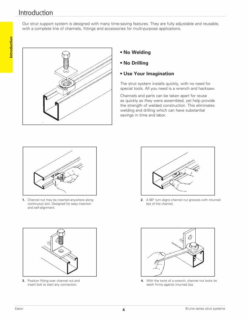
Our strut support system is designed with many time-saving features. They are fully adjustable and reusable, with a complete line of channels, fittings and accessories for multi-purpose applications.
• No Welding
• No Drilling
• Use Your Imagination
The strut system installs quickly, with no need for special tools. All you need is a wrench and hacksaw.
Channels and parts can be taken apart for reuseas quickly as they were assembled, yet help provide the strength of welded construction. This eliminateswelding and drilling which can have substantialsavings in time and labor.
1. Channel nut may be inserted anywhere along continuous slot. Designed for easy insertion and self-alignment.
2. A 90° turn aligns channel nut grooves with inturned lips of the channel.
3. Position fitting over channel nut and insert bolt to start any connection.
4. With the twist of a wrench, channel nut locks its teeth firmly against inturned lips.
Intr
oduc
tion
Introduction
B-Line series strut systems4Eaton
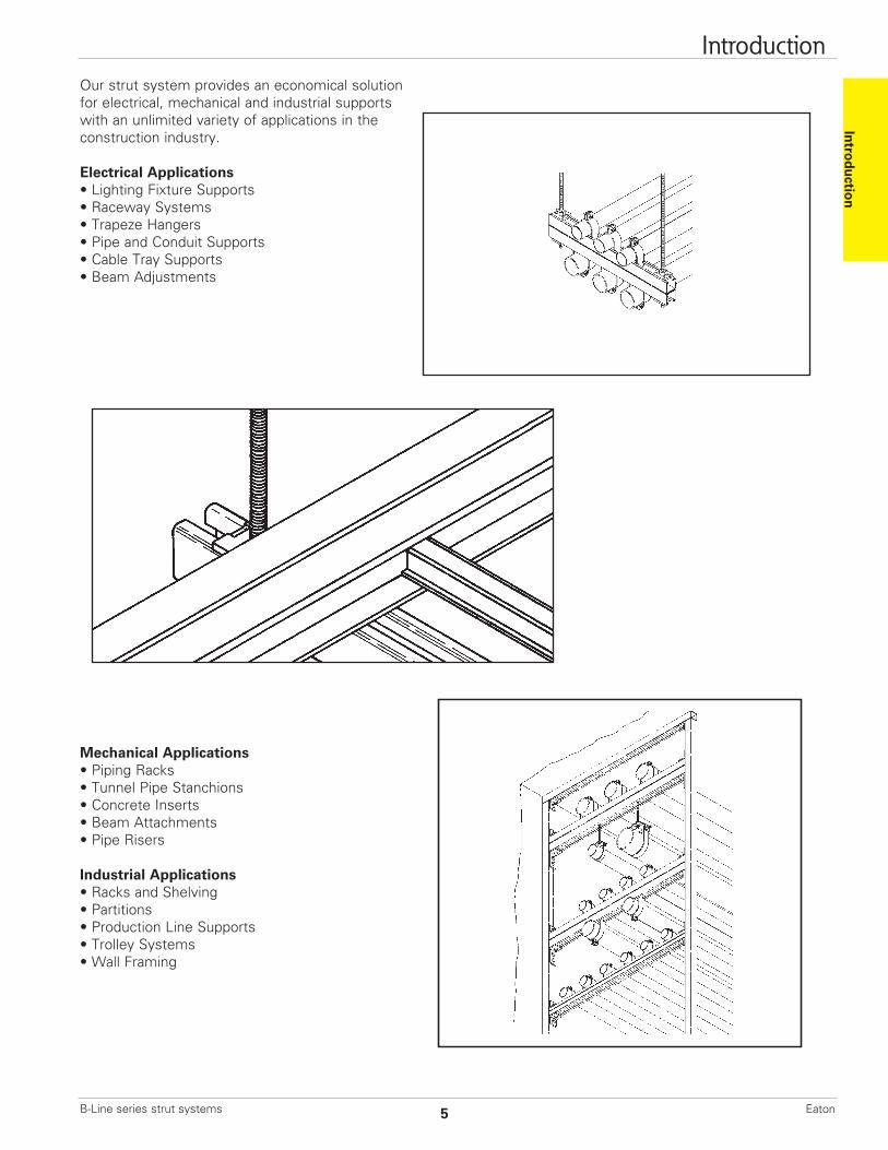
Our strut system provides an economical solution for electrical, mechanical and industrial supports with an unlimited variety of applications in the construction industry.
Electrical Applications• Lighting Fixture Supports• Raceway Systems• Trapeze Hangers• Pipe and Conduit Supports• Cable Tray Supports• Beam Adjustments
Mechanical Applications• Piping Racks• Tunnel Pipe Stanchions• Concrete Inserts• Beam Attachments• Pipe Risers
Industrial Applications• Racks and Shelving• Partitions• Production Line Supports• Trolley Systems• Wall Framing
Introduction Introduction
5B-Line series strut systems Eaton
Materials
Carbon SteelChannels made from high-quality carbon steel are continuously roll formed to precise dimensions. By cold working the steel mechanical properties are increased, allowing lightweight structures to carry the required load. Corrosion resistance of carbon steel varies widely with coating and alloy. See “Finishes” for more detailed information.
Stainless SteelStainless steel channel is available in AISI Type 304 or 316 material. Both are non-magnetic and belong to the austenitic stainless steels group, based on alloy content and crystallographic structure. Like carbon steel, stainless steel exhibits increased strength when cold worked by roll-forming.
Several conditions make the use of stainless steel ideal. These include reducing long term maintenance costs, high ambient temperatures, appearance, and stable structural properties such as yield strength, and high creep strength.
Type 304 resists most organic chemicals, dyestuffs and a wide variety of inorganic chemicals at elevated or cryogenic temperatures. Type 316 contains slightly more nickel and adds molybdenum to give it better corrosion resistance in chloride and sulfuric acid environments. For more information concerning the differences between types 304 and 316, visit Eaton.bline.com.
AluminumStandard aluminum channel is extruded from aluminum alloy 6063-T6. Strut fittings are made from aluminum alloy 5052-H32.
The high strength to weight ratio of channel made of aluminum helps greatly reduce the overall cost of installation through ease of handling and field cutting.
Aluminum owes its excellent corrosionresistance to its ability to form an aluminum oxide film that immediately reforms when scratched or cut. In most outdoor applications, aluminum has excellent resistance to “weatherin”. The resistance to chemicals, indoor or outdoor, can best be determined by tests conducted by the user with exposure to the specific conditions for which it is intended. The corrosion resistance of aluminum to some commonly known chemicals is shown in the CorrosionChart on page 10. For further information, contact us or the Aluminum Association.
FiberglassWe offer two fire retardant (FR) resins for strut systems, polyester and vinyl ester. Both resins are ideal for corrosive environments or nonconductive applications with moderate strength requirements. Some common types of environments where Vinyl Ester Resins are recommended, that Poly Esters are not, are paper mills, most any metal plating operation and any condition with
concentrated levels of Chlorine, [ Cl- ]. Please consult our fiberglass corrosion resistance charts on page 184 for specific chemical recommendation data.
Unlike other base materials depicted in this catalog, fiberglass exhibits unique physical property changes when operating in elevated temperature conditions that are a fraction of increase compared to steel or aluminum. Thus, it is advised against using fiberglass in temperatures greater than 200° F.
Please refer to the “Corrosion ResistanceGuid” on page 184 for specific applications.
The fiberglass strut systems are manufactured from glass fiber-reinforced plastic shapes that meet ASTM E-84, Class 1 Flame Rating and self-extinguishing requirements of ASTM D-635. A surface veil is applied during pultrusion to insure a resin-rich surface and ultraviolet resistance.
While polyester is sufficient for most uses,vinyl ester is suitable for a broader range of environments.
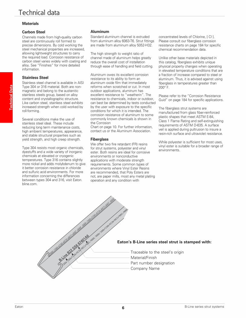
B-Line B22 SS6 87401A6
Eaton’s B-Line series steel strut is stamped with:
Traceable to the steel’s origin Material/Finish Part number designation Company Name
Tech
nica
l Dat
a Technical data
B-Line series strut systems6Eaton
Finishes
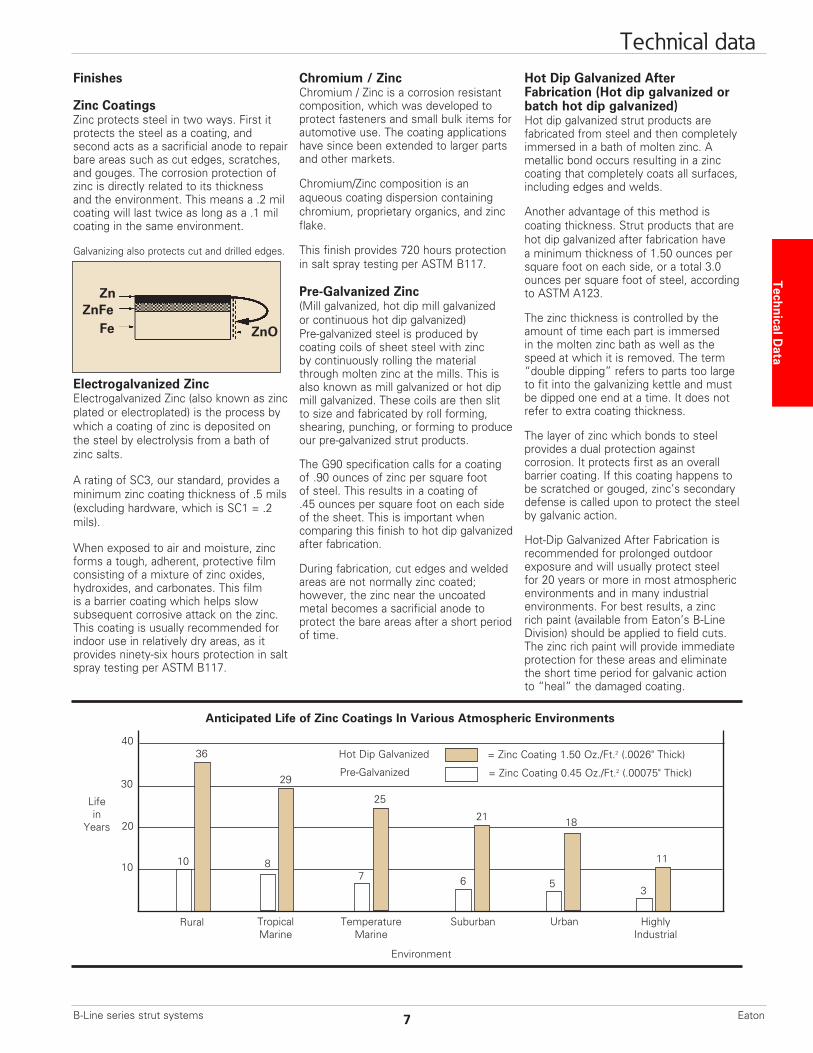
Zinc CoatingsZinc protects steel in two ways. First itprotects the steel as a coating, and second acts as a sacrificial anode to repair bare areas such as cut edges, scratches, and gouges. The corrosion protection of zinc is directly related to its thickness and the environment. This means a .2 mil coating will last twice as long as a .1 mil coating in the same environment.
Galvanizing also protects cut and drilled edges.
Electrogalvanized ZincElectrogalvanized Zinc (also known as zinc plated or electroplated) is the process by which a coating of zinc is deposited on the steel by electrolysis from a bath of zinc salts.
A rating of SC3, our standard, provides a minimum zinc coating thickness of .5 mils (excluding hardware, which is SC1 = .2 mils).
When exposed to air and moisture, zinc forms a tough, adherent, protective film consisting of a mixture of zinc oxides, hydroxides, and carbonates. This film is a barrier coating which helps slow subsequent corrosive attack on the zinc. This coating is usually recommended for indoor use in relatively dry areas, as it provides ninety-six hours protection in salt spray testing per ASTM B117.
Chromium / Zinc Chromium / Zinc is a corrosion resistantcomposition, which was developed toprotect fasteners and small bulk items forautomotive use. The coating applicationshave since been extended to larger parts and other markets.
Chromium/Zinc composition is an aqueous coating dispersion containing chromium, proprietary organics, and zinc flake.
This finish provides 720 hours protection in salt spray testing per ASTM B117.
Pre-Galvanized Zinc(Mill galvanized, hot dip mill galvanized or continuous hot dip galvanized) Pre-galvanized steel is produced by coating coils of sheet steel with zinc by continuously rolling the material through molten zinc at the mills. This is also known as mill galvanized or hot dip mill galvanized. These coils are then slit to size and fabricated by roll forming, shearing, punching, or forming to produce our pre-galvanized strut products.
The G90 specification calls for a coating of .90 ounces of zinc per square foot of steel. This results in a coating of .45 ounces per square foot on each side of the sheet. This is important when comparing this finish to hot dip galvanized after fabrication.
During fabrication, cut edges and welded areas are not normally zinc coated; however, the zinc near the uncoated metal becomes a sacrificial anode to protect the bare areas after a short period of time.
Hot Dip Galvanized After Fabrication (Hot dip galvanized or batch hot dip galvanized)Hot dip galvanized strut products are fabricated from steel and then completely immersed in a bath of molten zinc. A metallic bond occurs resulting in a zinc coating that completely coats all surfaces, including edges and welds.
Another advantage of this method is coating thickness. Strut products that are hot dip galvanized after fabrication have a minimum thickness of 1.50 ounces per square foot on each side, or a total 3.0 ounces per square foot of steel, according to ASTM A123.
The zinc thickness is controlled by the amount of time each part is immersed in the molten zinc bath as well as the speed at which it is removed. The term “double dipping” refers to parts too large to fit into the galvanizing kettle and must be dipped one end at a time. It does not refer to extra coating thickness.
The layer of zinc which bonds to steel provides a dual protection against corrosion. It protects first as an overall barrier coating. If this coating happens to be scratched or gouged, zinc’s secondary defense is called upon to protect the steel by galvanic action.
Hot-Dip Galvanized After Fabrication is recommended for prolonged outdoor exposure and will usually protect steel for 20 years or more in most atmospheric environments and in many industrial environments. For best results, a zinc rich paint (available from Eaton’s B-Line Division) should be applied to field cuts. The zinc rich paint will provide immediate protection for these areas and eliminate the short time period for galvanic action to “heal” the damaged coating.
Anticipated Life of Zinc Coatings In Various Atmospheric Environments
Hot Dip Galvanized
Pre-Galvanized
= Zinc Coating 1.50 Oz./Ft.2 (.0026" Thick)
= Zinc Coating 0.45 Oz./Ft.2 (.00075" Thick)
Rural TropicalMarine
TemperatureMarine
HighlyIndustrial
Lifein
Years
Suburban
Environment
Urban
10
20
30
40
10
36
8
29
7
25
6
21
5
18
3
11
Zn
FeZnFe
ZnO
Technical Data
Technical data
7B-Line series strut systems Eaton
DURA GREEN and DURA-COPPER Epoxy CoatingsDURA GREEN™ and DURA-COPPER™ epoxy coatings are water borne epoxy coatings applied to B-Line series products by a precisely controlled cathodic electro-deposition process. This process is accomplished using a conveyor to transport channel and fittings through several cleaning, phosphatizing and application stages prior to being baked (See diagram below).
This custom-designed paint system is used for painting all channels, channel combinations, slotted angle, and fittings.
Samples are selected on a routine basis for salt spray (fog) testing to verify the quality of the finish. These tests are performed in accordance with ASTM B117 and evaluated and related according to ASTM D1654 (Tables 1 and 2).
The DURA GREEN and DURA-COPPER epoxy coatings have been tested and listed by Underwriters Laboratories in
accordance with “Standard for Surface Metal Raceway and Fittings, UL5” and “Standard for Pipe Hanger Equipment for Fire Protection Service, UL203”.
Due to DURA GREEN’s organically based composition, it seats itself into porous surfaces more completely and efficiently than zinc coatings. As these porous caverns are filled along the material profile, the outer finished surface demonstrates an increased smooth uniform plane which produces considerably less off-gasing when tested.
DURA GREEN channel meets or exceeds 100 level clean room standards. This was confirmed by testing the channel in accordance with Boeing (PCL) Standards, which are more stringent and complete than ASTM E595-93. DURA GREEN was found to be a superior finish, due in part to its proven application process.
Unscribed Scribed 1/8" (3.2) Creepage Type of Finish 5% Failure (1) from Scribe (1)
DURA GREEN Epoxy 1000 Hours 312 Hours
Mill Galv. (Pre-Galv.) G90 192 Hours 288 Hours
Perma-Green 438 Hours 231 Hours
Zinc Chromate 36 Hours 96 Hours
Industry Green (Range) 10 to 36 Hours 4 to 30 Hours
Salt Spray Test Results
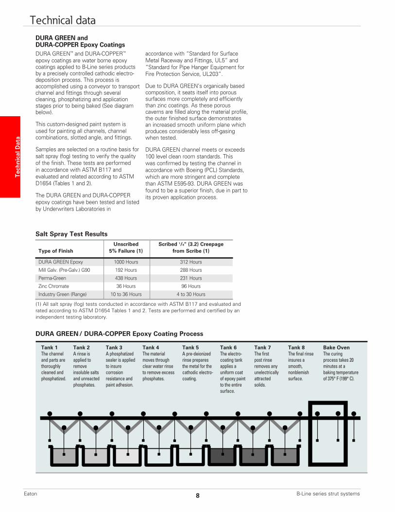
DURA GREEN / DURA-COPPER Epoxy Coating Process
Tank 1 Tank 2 Tank 3 Tank 4 Tank 5 Tank 6 Tank 7 Tank 8 Bake Oven The channel A rinse is A phosphatized The material A pre-deionized The electro- The first The final rinse The curing and parts are applied to sealer is applied moves through rinse prepares coating tank post rinse insures a process takes 20 thoroughly remove to insure clear water rinse the metal for the applies a removes any smooth, minutes at a cleaned and insoluble salts corrosion to remove excess cathodic electro- uniform coat unelectrically nonblemish baking temperature phosphatized. and unreacted resistance and phosphates. coating. of epoxy paint attracted surface. of 375° F (199° C). phosphates. paint adhesion. to the entire solids. surface.
(1) All salt spray (fog) tests conducted in accordance with ASTM B117 and evaluated and rated according to ASTM D1654 Tables 1 and 2. Tests are performed and certified by an independent testing laboratory.
Tech
nica
l Dat
a Technical data
B-Line series strut systems8Eaton
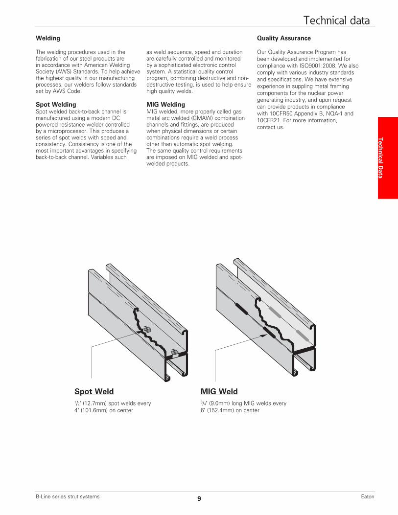
Welding
The welding procedures used in the fabrication of our steel products are in accordance with American Welding Society (AWS) Standards. To help achieve the highest quality in our manufacturing processes, our welders follow standards set by AWS Code.
Spot WeldingSpot welded back-to-back channel ismanufactured using a modern DC powered resistance welder controlled by a microprocessor. This produces a series of spot welds with speed and consistency. Consistency is one of the most important advantages in specifying back-to-back channel. Variables such
as weld sequence, speed and duration are carefully controlled and monitored by a sophisticated electronic control system. A statistical quality control program, combining destructive and non- destructive testing, is used to help ensure high quality welds.
MIG WeldingMIG welded, more properly called gas metal arc welded (GMAW) combination channels and fittings, are produced when physical dimensions or certain combinations require a weld process other than automatic spot welding. The same quality control requirements are imposed on MIG welded and spot- welded products.
Quality Assurance
Our Quality Assurance Program has been developed and implemented for compliance with ISO9001:2008. We also comply with various industry standards and specifications. We have extensive experience in suppling metal framing components for the nuclear power generating industry, and upon request can provide products in compliance with 10CFR50 Appendix B, NQA-1 and 10CFR21. For more information, contact us.
MIG WeldSpot Weld
Technical Data
Technical data
1/2" (12.7mm) spot welds every 4" (101.6mm) on center
3/4" (9.0mm) long MIG welds every 6" (152.4mm) on center
9B-Line series strut systems Eaton
CorrosionAll metal surfaces are affected by corrosion. Depending on the physical properties of the metal and the environment to which it is exposed, chemical or electromechanical corrosion may occur.
Atmospheric CorrosionAtmospheric corrosion occurs when metal is exposed to airborne liquids, solids or gases. Some sources of atmospheric corrosion are moisture, salt, dirt and sulphuric acid. This form of corrosion is typically more severe outdoors, especially near marine environments.
Chemical CorrosionChemical corrosion takes place when metal comes in direct contact with a corrosive solution. Some factors which affect the severity of chemical corrosion include: chemical concentration level, duration of contact, frequency of washing, and operating temperature.
Storage CorrosionWet storage stain (white rust) is caused by the entrapment of moisture between surfaces of closely packed and poorly ventilated material for an extended period. Wet storage stain is usually superficial, having no affect on the properties of the metal.
Light staining normally disappears with weathering. Medium to heavy buildup should be removed in order to allow the formation of normal protective film. Proper handling and storage will help to assure stain-free material. If product arrives wet, it should be unpacked and dried before storage. Dry material should be stored in a well ventilated “low moisture” environment to avoid condensation formation. Outdoor storage is undesirable, and should be avoided whenever possible.
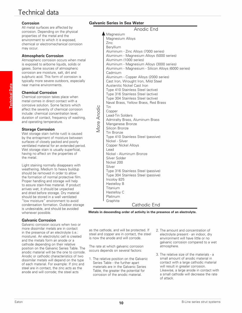
Galvanic CorrosionGalvanic corrosion occurs when two or more dissimilar metals are in contact in the presence of an electrolyte (i.e.: moisture). An electrolytic cell is created and the metals form an anode or a cathode depending on their relative position on the Galvanic Series Table. The anodic material will be the one to corrode. Anodic or cathodic characteristics of two dissimilar metals will depend on the type of each material. For example: If zinc and steel are in contact, the zinc acts as the anode and will corrode; the steel acts
as the cathode, and will be protected. If steel and copper are in contact, the steel is now the anode and will corrode.
The rate at which galvanic corrosion occurs depends on several factors:
1. The relative position on the Galvanic Series Table - the further apart materials are in the Galvanic Series Table, the greater the potential for corrosion of the anodic material.
Galvanic Series in Sea Water
Metals in descending order of activity in the presence of an electrolyte.
2. The amount and concentration of electrolyte present - an indoor, dry environment will have little or no galvanic corrosion compared to a wet atmosphere.
3. The relative size of the materials - a small amount of anodic material in contact with a large cathodic material will result in greater corrosion. Likewise, a large anode in contact with a small cathode will decrease the rate of attack.
Magnesium Magnesium Alloys
Zinc Beryllium Aluminum - Zinc Alloys (7000 series) Aluminum - Magnesium Alloys (5000 series) Aluminum (1000 series) Aluminum - Magnesium Alloys (3000 series) Aluminum - Magnesium - Silicon Alloys (6000 series) Cadmium Aluminum - Copper Alloys (2000 series) Cast Iron, Wrought Iron, Mild Steel Austenitic Nickel Cast Iron Type 410 Stainless Steel (active) Type 316 Stainless Steel (active) Type 304 Stainless Steel (active) Naval Brass, Yellow Brass, Red Brass Tin Copper Lead-Tin Solders Admiralty Brass, Aluminum Brass Manganese Bronze Silicon Bronze Tin Bronze Type 410 Stainless Steel (passive) Nickel - Silver Copper Nickel Alloys Lead Nickel - Aluminum Bronze Silver Solder Nickel 200 Silver Type 316 Stainless Steel (passive) Type 304 Stainless Steel (passive) Incoloy 825 Hastelloy B Titanium Hastelloy C Platinum Graphite
Mor
e A
nodi
c
Anodic End
Cathodic End
Tech
nica
l Dat
a Technical data
B-Line series strut systems10Eaton
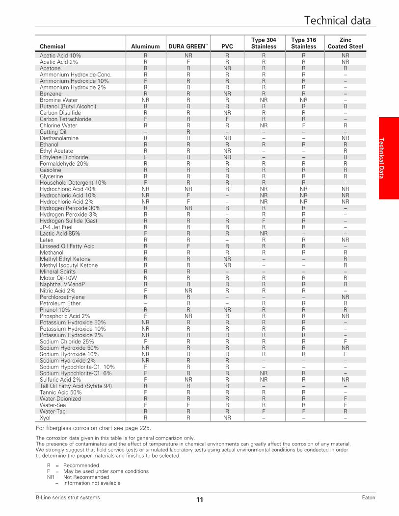
Type 304 Type 316 Zinc Chemical Aluminum DURA GREEN™ PVC Stainless Stainless Coated Steel
Acetic Acid 10% R NR R R R NR Acetic Acid 2% R F R R R NR Acetone R R NR R R R Ammonium Hydroxide-Conc. R R R R R – Ammonium Hydroxide 10% F R R R R – Ammonium Hydroxide 2% R R R R R – Benzene R R NR R R – Bromine Water NR R R NR NR – Butanol (Butyl Alcohol) R R R R R R Carbon Disulfide R R NR R R – Carbon Tetrachloride F R F R R – Chlorine Water R R R NR F R Cutting Oil – R – – – – Diethanolamine R R NR – – NR Ethanol R R R R R R Ethyl Acetate R R NR – – R Ethylene Dichloride F R NR – – R Formaldehyde 20% R R R R R R Gasoline R R R R R R Glycerine R R R R R R Household Detergent 10% F R R R R – Hydrochloric Acid 40% NR NR R NR NR NR Hydrochloric Acid 10% NR F – NR NR NR Hydrochloric Acid 2% NR F – NR NR NR Hydrogen Peroxide 30% R NR R R R – Hydrogen Peroxide 3% R R – R R – Hydrogen Sulfide (Gas) R R R F R – JP-4 Jet Fuel R R R R R – Lactic Acid 85% F R R NR – – Latex R R – R R NR Linseed Oil Fatty Acid R F R R R – Methanol R R R R R R Methyl Ethyl Ketone R R NR – – R Methyl Isobutyl Ketone R R NR – – R Mineral Spirits R R – – – – Motor Oil-10W R R R R R R Naphtha, VMandP R R R R R R Nitric Acid 2% F NR R R R – Perchloroethylene R R – – – NR Petroleum Ether – R – R R R Phenol 10% R R NR R R R Phosphoric Acid 2% F NR R R R NR Potassium Hydroxide 50% NR R R R R – Potassium Hydroxide 10% NR R R R R – Potassium Hydroxide 2% NR R R R R – Sodium Chloride 25% F R R R R F Sodium Hydroxide 50% NR R R R R NR Sodium Hydroxide 10% NR R R R R F Sodium Hydroxide 2% NR R R – – – Sodium Hypochlorite-C1. 10% F R R – – – Sodium Hypochlorite-C1. 6% F R R NR R – Sulfuric Acid 2% F NR R NR R NR Tall Oil Fatty Acid (Syfate 94) R R R – – – Tannic Acid 50% F R R R R – Water-Deionized R R R R R F Water-Sea F F R R R F Water-Tap R R R F F R Xyol R R NR – – –
For fiberglass corrosion chart see page 225.
The corrosion data given in this table is for general comparison only.The presence of contaminates and the effect of temperature in chemical environments can greatly affect the corrosion of any material.We strongly suggest that field service tests or simulated laboratory tests using actual environmental conditions be conducted in order to determine the proper materials and finishes to be selected.
R = Recommended F = May be used under some conditions NR = Not Recommended – Information not available
Technical Data
Technical data
11B-Line series strut systems Eaton
Design of B-Line seriesStrut Systems
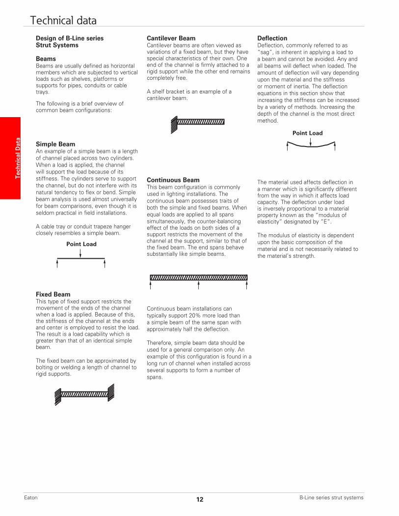
BeamsBeams are usually defined as horizontal members which are subjected to vertical loads such as shelves, platforms or supports for pipes, conduits or cable trays.
The following is a brief overview of common beam configurations:
Simple BeamAn example of a simple beam is a length of channel placed across two cylinders. When a load is applied, the channel will support the load because of its stiffness. The cylinders serve to support the channel, but do not interfere with its natural tendency to flex or bend. Simple beam analysis is used almost universally for beam comparisons, even though it is seldom practical in field installations.
A cable tray or conduit trapeze hangerclosely resembles a simple beam.
Fixed BeamThis type of fixed support restricts the movement of the ends of the channel when a load is applied. Because of this, the stiffness of the channel at the ends and center is employed to resist the load. The result is a load capability which is greater than that of an identical simple beam.
The fixed beam can be approximated by bolting or welding a length of channel to rigid supports.
Cantilever BeamCantilever beams are often viewed as variations of a fixed beam, but they have special characteristics of their own. One end of the channel is firmly attached to a rigid support while the other end remains completely free.
A shelf bracket is an example of a cantilever beam.
Continuous BeamThis beam configuration is commonly used in lighting installations. The continuous beam possesses traits of both the simple and fixed beams. When equal loads are applied to all spans simultaneously, the counter-balancing effect of the loads on both sides of a support restricts the movement of the channel at the support, similar to that of the fixed beam. The end spans behave substantially like simple beams.
Continuous beam installations can typically support 20% more load than a simple beam of the same span with approximately half the deflection.
Therefore, simple beam data should be used for a general comparison only. An example of this configuration is found in a long run of channel when installed across several supports to form a number of spans.
DeflectionDeflection, commonly referred to as “sag”, is inherent in applying a load to a beam and cannot be avoided. Any and all beams will deflect when loaded. The amount of deflection will vary depending upon the material and the stiffness or moment of inertia. The deflection equations in this section show that increasing the stiffness can be increased by a variety of methods. Increasing the depth of the channel is the most direct method.
The material used affects deflection in a manner which is significantly different from the way in which it affects load capacity. The deflection under load is inversely proportional to a material property known as the “modulus of elasticity” designated by “E”.
The modulus of elasticity is dependent upon the basic composition of the material and is not necessarily related to the material’s strength.
Point Load
Point Load
Tech
nica
l Dat
a Technical data
B-Line series strut systems12Eaton
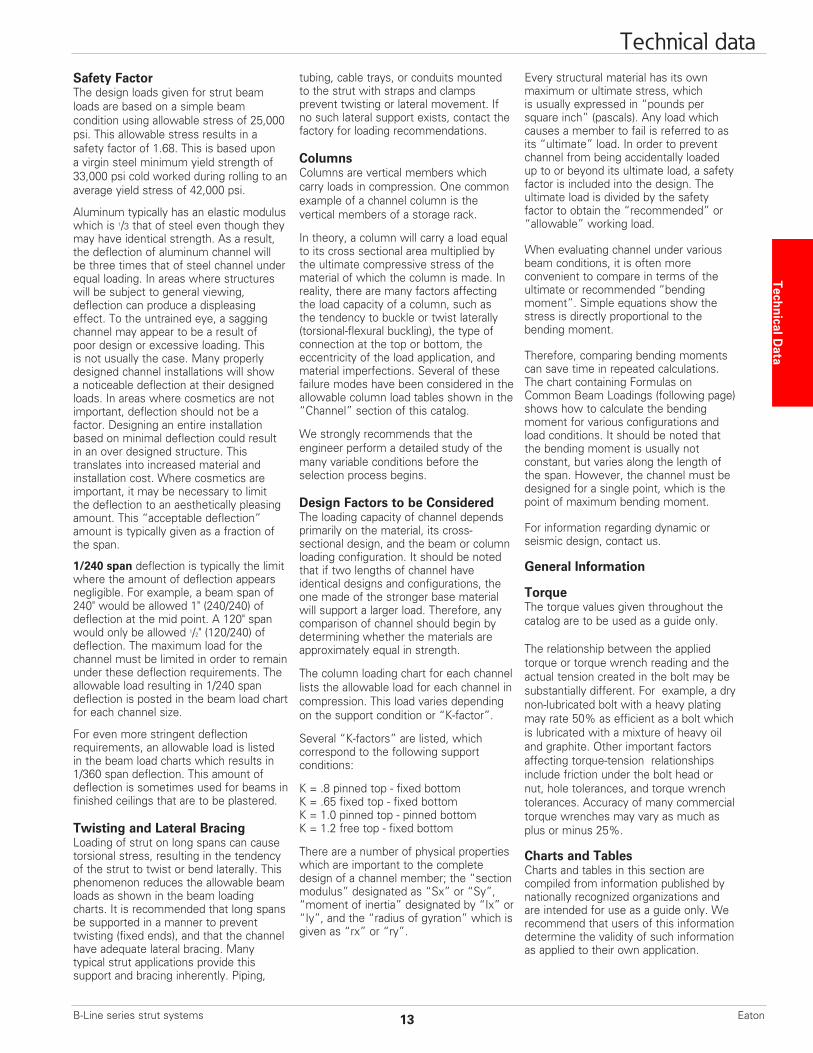
Safety FactorThe design loads given for strut beam loads are based on a simple beam condition using allowable stress of 25,000 psi. This allowable stress results in a safety factor of 1.68. This is based upon a virgin steel minimum yield strength of 33,000 psi cold worked during rolling to an average yield stress of 42,000 psi.
Aluminum typically has an elastic moduluswhich is 1/3 that of steel even though theymay have identical strength. As a result, the deflection of aluminum channel will be three times that of steel channel under equal loading. In areas where structures will be subject to general viewing, deflection can produce a displeasing effect. To the untrained eye, a sagging channel may appear to be a result of poor design or excessive loading. This is not usually the case. Many properly designed channel installations will show a noticeable deflection at their designed loads. In areas where cosmetics are not important, deflection should not be a factor. Designing an entire installation based on minimal deflection could result in an over designed structure. This translates into increased material and installation cost. Where cosmetics are important, it may be necessary to limit the deflection to an aesthetically pleasing amount. This “acceptable deflection” amount is typically given as a fraction of the span.
1/240 span deflection is typically the limit where the amount of deflection appears negligible. For example, a beam span of 240" would be allowed 1" (240/240) of deflection at the mid point. A 120" span would only be allowed 1/2" (120/240) of deflection. The maximum load for the channel must be limited in order to remain under these deflection requirements. The allowable load resulting in 1/240 span deflection is posted in the beam load chart for each channel size.
For even more stringent deflectionrequirements, an allowable load is listed in the beam load charts which results in 1/360 span deflection. This amount of deflection is sometimes used for beams in finished ceilings that are to be plastered.
Twisting and Lateral BracingLoading of strut on long spans can causetorsional stress, resulting in the tendency of the strut to twist or bend laterally. Thisphenomenon reduces the allowable beamloads as shown in the beam loading charts. It is recommended that long spans be supported in a manner to prevent twisting (fixed ends), and that the channel have adequate lateral bracing. Many typical strut applications provide this support and bracing inherently. Piping,
tubing, cable trays, or conduits mounted to the strut with straps and clamps prevent twisting or lateral movement. If no such lateral support exists, contact the factory for loading recommendations.
ColumnsColumns are vertical members which carry loads in compression. One commonexample of a channel column is the vertical members of a storage rack.
In theory, a column will carry a load equalto its cross sectional area multiplied by the ultimate compressive stress of the material of which the column is made. In reality, there are many factors affecting the load capacity of a column, such as the tendency to buckle or twist laterally (torsional-flexural buckling), the type of connection at the top or bottom, the eccentricity of the load application, and material imperfections. Several of these failure modes have been considered in the allowable column load tables shown in the “Channel” section of this catalog.
We strongly recommends that the engineer perform a detailed study of the many variable conditions before theselection process begins.
Design Factors to be ConsideredThe loading capacity of channel dependsprimarily on the material, its cross- sectional design, and the beam or column loading configuration. It should be noted that if two lengths of channel have identical designs and configurations, the one made of the stronger base material will support a larger load. Therefore, any comparison of channel should begin by determining whether the materials are approximately equal in strength.
The column loading chart for each channel lists the allowable load for each channel in compression. This load varies depending on the support condition or “K-factor”.
Several “K-factors” are listed, whichcorrespond to the following supportconditions:
K = .8 pinned top - fixed bottomK = .65 fixed top - fixed bottomK = 1.0 pinned top - pinned bottomK = 1.2 free top - fixed bottom
There are a number of physical properties which are important to the complete design of a channel member; the “section modulus” designated as “Sx” or “Sy”, “moment of inertia” designated by “Ix” or “Iy”, and the “radius of gyration” which is given as “rx” or “ry”.
Every structural material has its own maximum or ultimate stress, which is usually expressed in “pounds per square inch” (pascals). Any load which causes a member to fail is referred to as its “ultimate” load. In order to prevent channel from being accidentally loaded up to or beyond its ultimate load, a safety factor is included into the design. The ultimate load is divided by the safety factor to obtain the “recommended” or “allowable” working load.
When evaluating channel under variousbeam conditions, it is often more convenient to compare in terms of the ultimate or recommended “bending moment”. Simple equations show the stress is directly proportional to the bending moment.
Therefore, comparing bending momentscan save time in repeated calculations. The chart containing Formulas on Common Beam Loadings (following page) shows how to calculate the bending moment for various configurations and load conditions. It should be noted that the bending moment is usually not constant, but varies along the length of the span. However, the channel must be designed for a single point, which is the point of maximum bending moment.
For information regarding dynamic or seismic design, contact us.
General Information
TorqueThe torque values given throughout the catalog are to be used as a guide only.
The relationship between the applied torque or torque wrench reading and the actual tension created in the bolt may be substantially different. For example, a dry non-lubricated bolt with a heavy plating may rate 50% as efficient as a bolt which is lubricated with a mixture of heavy oil and graphite. Other important factors affecting torque-tension relationships include friction under the bolt head or nut, hole tolerances, and torque wrench tolerances. Accuracy of many commercial torque wrenches may vary as much as plus or minus 25%.
Charts and TablesCharts and tables in this section arecompiled from information published by nationally recognized organizations and are intended for use as a guide only. We recommend that users of this information determine the validity of such information as applied to their own application.
Technical Data
Technical data
13B-Line series strut systems Eaton
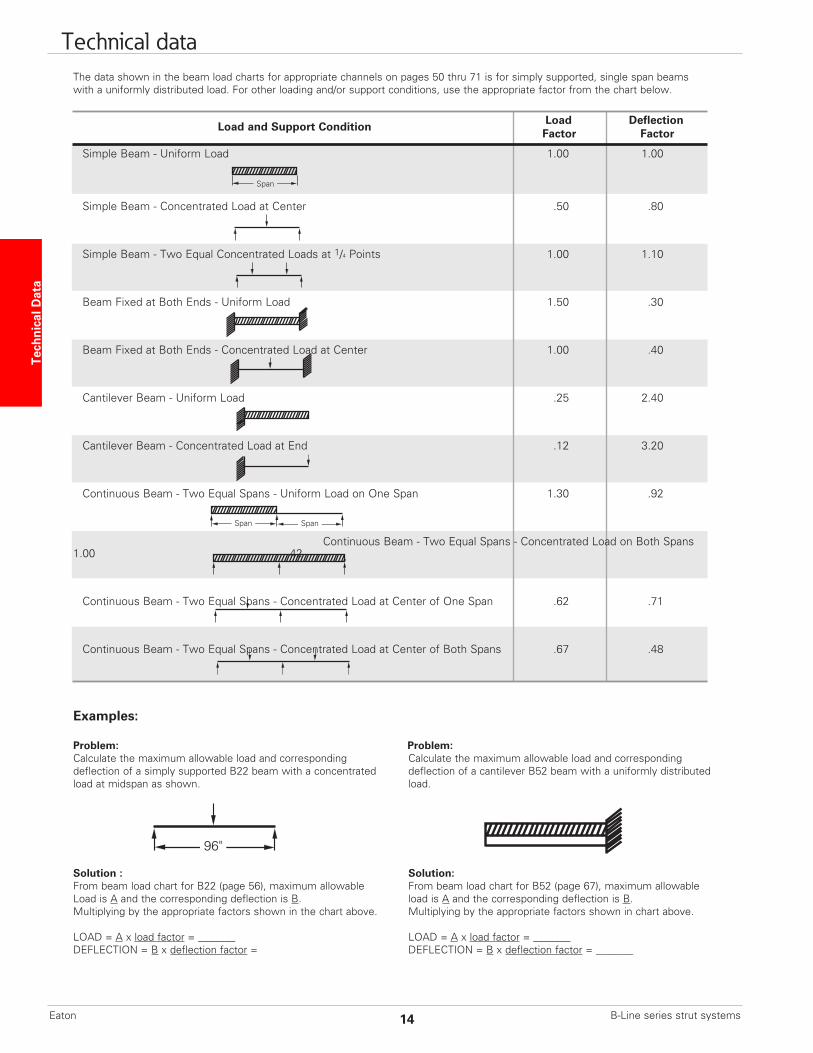
Load and Support Condition Load Deflection Factor Factor
Simple Beam - Uniform Load 1.00 1.00
Simple Beam - Concentrated Load at Center .50 .80
Simple Beam - Two Equal Concentrated Loads at 1/4 Points 1.00 1.10
Beam Fixed at Both Ends - Uniform Load 1.50 .30
Beam Fixed at Both Ends - Concentrated Load at Center 1.00 .40
Cantilever Beam - Uniform Load .25 2.40
Cantilever Beam - Concentrated Load at End .12 3.20
Continuous Beam - Two Equal Spans - Uniform Load on One Span 1.30 .92
Continuous Beam - Two Equal Spans - Concentrated Load on Both Spans 1.00 .42
Continuous Beam - Two Equal Spans - Concentrated Load at Center of One Span .62 .71
Continuous Beam - Two Equal Spans - Concentrated Load at Center of Both Spans .67 .48
Span
SpanSpan
The data shown in the beam load charts for appropriate channels on pages 50 thru 71 is for simply supported, single span beams with a uniformly distributed load. For other loading and/or support conditions, use the appropriate factor from the chart below.
Examples:
Problem: Problem:Calculate the maximum allowable load and corresponding Calculate the maximum allowable load and correspondingdeflection of a simply supported B22 beam with a concentrated deflection of a cantilever B52 beam with a uniformly distributedload at midspan as shown. load.
Solution : Solution:From beam load chart for B22 (page 56), maximum allowable From beam load chart for B52 (page 67), maximum allowableLoad is A and the corresponding deflection is B. load is A and the corresponding deflection is B.Multiplying by the appropriate factors shown in the chart above. Multiplying by the appropriate factors shown in chart above.
LOAD = A x load factor = _______ LOAD = A x load factor = _______DEFLECTION = B x deflection factor = DEFLECTION = B x deflection factor = _______
96"
Tech
nica
l Dat
a Technical data
B-Line series strut systems14Eaton
Brackets [ ] indicate alternativespecifications which may be substituted by the project engineer.
Part 1 - General1.01 Work IncludedA. Continuous slot, bolted framing channels and all associated fittings and hardware.
B. Trapeze type supports for cable tray, conduit, pipe and other similar systems.
C. Use of bolted metal framing as a surface metal raceway.
1.02 ReferencesA. ASTM A108 - Specification for SteelBars, Carbon, Cold Finished, StructuralQuality.
B. ASTM A123 - Specification for Zinc (hot-dip galvanized) Coatings on Products Fabricated from Rolled, Pressed, and Forged Steel Shapes, Plates, Bars and Strips.
C. ASTM A1011, 33,000 PSI min. yield - Specification for Steel, Sheet and Strip, Carbon, Hot-Rolled, Structural Quality.
D. ASTM B633 - Specification for Electrodeposited Coatings of Zinc on Iron and Steel.
E. ASTM A653 33,000 PSI min. yield G90- Specification for Steel Sheet, Zinc Coated (Galvanized) by the Hot-Dip Process, Structural Quality.
F. ASTM A1018 - Standard Specificationfor Steel, Sheet and Strip, Heavy-ThicknessCoils, Carbon, Hot-Rolled, StructuralQuality.
G. MFMA - Metal Framing StandardsPublication, MFMA-4.
1.03 Quality AssuranceA. Manufacturers: Firms regularly engaged in the manufacture of bolted metal framing of the types required, whose products have been in satisfactory use in similar service for not less than 5 years.
B. A material heat code number shall be stamped on all strut and fittings. This is required to maintain traceability of the product to the material test reports to the ASTM standard.
C. For stainless steel items, the part number shall contain a material designator (EXAMPLE: B-Line B22SS6 for type 316 or B22SS4 for type 304), or a separate stamp shall be included to reference the type of material used.
D. MFMA Compliance: comply with the latest revision of MFMA Standard Publication Number MFMA-4, “Metal Framing”.
E. NEC Compliance: Comply with the latest revision NFPA 70 - Article 352 “Surface Metal Raceways and Surface Nonmetallic Raceways”.
F. UL Compliance: Comply with UL “Standard for Surface Metal Raceway and Fittings”.
1.04 SubmittalsA. Submit drawings of strut and accessories including clamps, brackets, hanger rods and fittings.
B. Submit manufacturer’s product data on strut channels including, but not limited to, types, materials, finishes, gauge thickness and hole patterns. For each different strut cross section, submit cross sectional properties including Section Modulus (Sx) and Moment of Inertia (Ix).
1.05 Delivery, Storage and HandlingA. Deliver strut systems and components carefully to avoid breakage, denting, and scoring finishes. Do not install damaged equipment.
B. Store strut systems and components in original cartons and in clean dry space; protect from weather and construction traffic.
Part 2 - Products 2.01 Acceptable ManufacturersA. Manufacturer: Subject to compliance with these specifications, strut systems to be installed shall be as manufactured by Eaton’s B-Line Business [or engineer approved equal.]
2.02 Strut Channels and ComponentsA. General: Strut shall be 15/8" wide in varying heights and welded combinations as required to meet load capacities and designs indicated on the drawings.
B. Material and Finish: Material and finish specifications for each strut type are as follows:
1. Aluminum: Strut shall be manufactured of extruded aluminum alloy 6063-T6. All fittings and hardware shall be zinc plated according to ASTM B633. For outdoor use, all fittings and hardware shall be stainless steel Type 316 [Type 304] or chromium zinc, ASTM F1136 Gr. 3.
2. Epoxy Painted: Strut shall be made from steel meeting the minimum mechanical properties of ASTM A1011 33,000 PSI min yield, then painted with water borne epoxy applied by a cathodic electro-deposition
process. Fittings shall be manufactured from steel meeting the minimum requirements of ASTM A1018 33,000 PSI min. yield. The fittings shall have the same epoxy finish as the strut. Threaded hardware shall be zinc plated in accordance with ASTM B633 Service Class 1 (SC1). Service Class 1 is not an acceptable coating for fittings or components other than threaded hardware.
3. Pre-Galvanized Steel: Strut shall be made from structural quality steel meeting the minimum mechanical properties of ASTM A653 33,000 PSI min. yield, mill galvanized coating designation G90. Fittings shall be manufactured from steel meeting the minimum requirements of ASTM A1018 33,000 PSI min. yield and zinc plated in accordance with ASTM B633 service class 3 (SC3). Threaded hardware shall be zinc plated in accordance with ASTM B633 Service Class 1 (SC1). Service Class 1 is not an acceptable coating for fittings or components other than threaded hardware.
4. Hot-Dip Galvanized Steel: Strut shall be made from structural quality steel meeting the minimum mechanical properties of ASTM A1011 33,000 PSI min. yield and shall be hot-dip galvanized after fabrication in accordance with ASTM A123. Fittings shall be manufactured from steel meeting the minimum requirements of ASTM A1018 33,000 PSI min. yield, and hot-dip galvanized after fabrication in accordance with ASTM A123. All hardware shall be stainless steel Type 316 [Type 304] or chromium zinc ASTM F1136 Gr. 3. All hot-dip galvanized after fabrication products must be returned to point of manufacture after coating for inspection and removal of all sharp burrs.
5. Stainless Steel: All strut, fittings and hardware shall be made of AISI Type 316 [Type 304] stainless steel as indicated. Channels must be identified as required in previous section 1.03 Quality Assurance.
Part 3 - Execution3.01 InstallationA. Install strut as indicated; in accordance with equipment manufacturer’s recommendations, and with recognized industry practices.
B. All nuts and bolts shall be tightened to the following values.
Recommended Bolted Metal Framing (Strut System) Specification
Bolt Size Torque (ft-lbs) 1/4-20 6 5/16-18 11 3/8-16 19 1/2-13 50
Technical Data
Technical data
15B-Line series strut systems Eaton
4Dim
ensi
on S
trut
The 4Dimension strut system has been discontinued. Therefore, pages 16 to 47 have been removed from this catalog.
B-Line series strut systems16Eaton


