Robotics and Controls Tuesday Lab Group 1 Lab 4 – The GMF Work Cell Lab Conducted: 2/21/2006 Introduction This is the third and final lab involving the GM-Fanuc cylindrical robots. Throughout the previous two lab experiments, the students have familiarized themselves with standard operating procedures, concepts, and system synchronization. The purpose of this third experiment is to acquaint the students with the techniques needed to make multiple pieces of equipment work together to accomplish a task. Specifically, communication will be inserted into the processes of the previous RC controller laboratories code in order to enable cooperative communication between the 5-axis and 4-Axis GMF robots. The RC controller’s ability to interact with other pieces of equipment within the work cell was explored. By use of isolation relays, and the system device’s input and output (SDI/SDO) interface, a “Master-Slave” controller scheme was developed. This scheme transfers tasks between the two robots via a “handshaking” technique in order to pick, place, paint, and return a single part back to the main factory line. Work Cell Layout In order to fully understand the robots and their purpose it is best to view the work space in which they will be conducting the needed task of moving parts to be painted from an incoming rotary table to a painting conveyor, and returning them to the rotary table. On the following page the work cell layout is shown incorporating all pieces of equipment including robots, tables, work benches and conveyors into it (See Figures 1 and 2). The numbers within the figures on the following diagram coincide with the line of code that will be executed at that specific location in the work space. Hence, the robot’s location throughout the code can be followed for 1 of 19
Transcript
Robotics and Controls Tuesday Lab Group 1Lab 4 – The GMF Work Cell Lab Conducted: 2/21/2006
Introduction
This is the third and final lab involving the GM-Fanuc cylindrical robots. Throughout the previous two lab experiments, the students have familiarized themselves with standard operating procedures, concepts, and system synchronization. The purpose of this third experiment is to acquaint the students with the techniques needed to make multiple pieces of equipment work together to accomplish a task. Specifically, communication will be inserted into the processes of the previous RC controller laboratories code in order to enable cooperative communication between the 5-axis and 4-Axis GMF robots.
The RC controller’s ability to interact with other pieces of equipment within the work cell was explored. By use of isolation relays, and the system device’s input and output (SDI/SDO) interface, a “Master-Slave” controller scheme was developed. This scheme transfers tasks between the two robots via a “handshaking” technique in order to pick, place, paint, and return a single part back to the main factory line.
Work Cell Layout
In order to fully understand the robots and their purpose it is best to view the work space in which they will be conducting the needed task of moving parts to be painted from an incoming rotary table to a painting conveyor, and returning them to the rotary table.
On the following page the work cell layout is shown incorporating all pieces of equipment including robots, tables, work benches and conveyors into it (See Figures 1 and 2). The numbers within the figures on the following diagram coincide with the line of code that will be executed at that specific location in the work space. Hence, the robot’s location throughout the code can be followed for each step by matching the code with the location on the work cell diagram. To assure the safety and reliability for the robot’s arm movement, safety points were programmed into the code ensuring all of the joint locations are accounted for and known. Safety points were placed above the rotating table for the master robot, and the work bench for both the master and slave robots. Also, the slave robot had safe points placed above the conveyor for safe loading and unloading. Safety points were used at any time when the robot arm was in tight quarters and move towards or away a product part. An intermediate safety point was added in open spaces, this was not a necessary part of the code but this better insures that the arm remains consistent each time the process runs. Another reason as to why safe points are introduced into the programming code is to allow for speed changes in the program. The desired speed for the robot’s arm was programmed 1 through 8, dependent on the direction, position and use of the end gripper. Higher speeds, such as 7 or 8, were desired in open areas to try and reduce cycle time of the entire procedure, and slow speeds, 1 through 4, were needed for a process in the code that required the end gripper to pick up or drop off a part. The speed of the robot was slowed down slightly, to a medium range number, with a part on the gripper to insure the safety and to maintain consistent orientation of the part. Knowing that the robot’s joints are all in a safe location displays good pose control.
1 of 12
Robotics and Controls Tuesday Lab Group 1Lab 4 – The GMF Work Cell Lab Conducted: 2/21/2006
ANALYSIS OF THE MASTER CODE
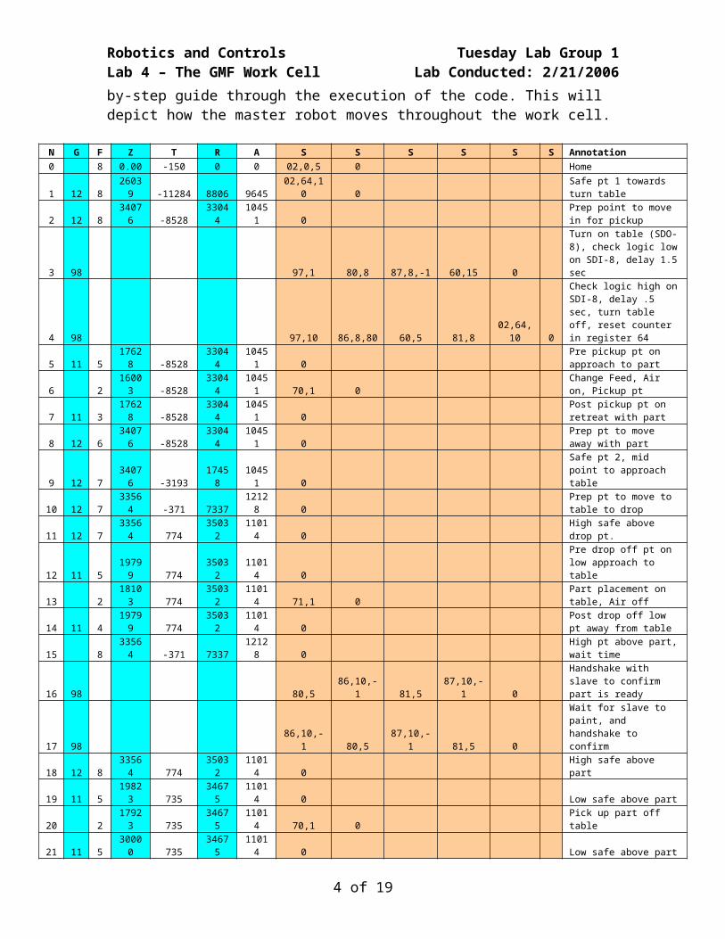
The table on the following page is the annotated code used for the master 4-axis robot. Following the code is a step-by-step guide through the execution of the code. This will depict how the master robot moves throughout the work cell.
2 of 12
Robotics and Controls Tuesday Lab Group 1Lab 4 – The GMF Work Cell Lab Conducted: 2/21/2006
N G F Z T R A S S S S S S Annotation0 8 0.00 -150 0 0 02,0,5 0 Home
30 12 8 23853 -13515 0 10451 97,2 81,8 0 Prep pt to move away to home base
31 98 80,6 86,10,-1 81,6 87,10,-1 0 Handshake with slave to go home
32 8
0.00
-150
0 0 99
Home, W/ end program and rewind
3 of 12
Robotics and Controls Tuesday Lab Group 1Lab 4 – The GMF Work Cell Lab Conducted: 2/21/2006
In the first line of the code, N0, there is a remnant of our old loop by defining a value of 5 in register number 0. This definition is not necessary for the operation of this program. In block N1, a new value of 10 is defined in register 64 as the robot moves to a safe point towards the turn table. This value will be used to designate the number of times to iterate through a constant amount of time established in Setting Parameter Data #10. This is one example of how the operator/programmer can establish a give time length when only given constant amounts of time. Using time in this manner is referred to as “timed input” as opposed to “blocking input.” An example of blocking input is the S87,8,-1 code in block N3. This code will wait forever until it reads logic low on the input. A drawback to this type of programming is that if the specific condition is never met, the program will never end. With “timed input,” there leaves a way for the program to terminate after a certain amount of time.
Continuing with our code, in block N3, a branch designator is assigned by the S97,1. Next, the output connection on terminal 8 is established by the S80,8 code. This effectively turns on the table, or conveyor. The program then waits for the signal to go logic low indefinitely on terminal 8 as designated by S87,8,-1. This will indicate that there is no part in front of the photo cell and the current part has moved away. Then a pause or delay of 1.5 seconds occurs.
In block N4, a branch designator is created by the S97,10 code. Next in the code is S86,8,80. What this S code does is wait for a part to enter the pickup area, which would make the system go logic high. The S86 code waits for the amount of time designated in Parameter Data #10, which happens to be 3.0 seconds, for the input 8 terminal to receive the 24V, making it logic high. If it does not go logic high in that 3 seconds, then the program will branch to S97,80, which is in block N29. This block will then decrement the value in register number 64 and make a comparison to zero. The S38,2 will branch to S97,2 (block N26) if the flag is < or = to zero, otherwise the S30,10 in N29 will make it branch back to the S97,10 (block N4) unconditionally. The basic principle is that this executes the 3 second wait a desired number of times as designated by the value in register 64. If the signal device input 8 terminal never goes logic high, meaning a part never shows up, the program will continue at block N30 heading towards home, telling the slave to go home, and finishing the program. If within the ten repeats of the 3 second intervals the input goes logic high, meaning a part has appeared, then the code will continue on block N4 with S60,5. This half-second delay allows enough time for the motor to disengage from the Geneva drive that turns the table in increments or step amounts. This is to prevent a load on the motor when it starts up again. After the half-second, the S81,8 code cuts power in the coil in the relay, effectively stopping the motor. After this has happened, the value of register 64 is reset to 10, which effectively resets the number of 3 second intervals that it should wait the next time.
Once a part has been seen by the photo eye, the program will continue on block N5, where the robot drops to a low safe point directly above the part. In block N6, the robot will drop down to the part and turn on the suction to the gripper using the RDO/RDI by the S70,1 command. Now that the robot has control of the part, in block N7 the robot will move to the low safe point above the pickup point, and then to the high safe point in
4 of 12
Robotics and Controls Tuesday Lab Group 1Lab 4 – The GMF Work Cell Lab Conducted: 2/21/2006block N8. The code in block N9 moves the master robot to a safe point between the turn table and the workbench where the part is to be dropped. Block N10 designates the position above the corner of the workbench. This position will be used as a waiting point while the slave robot takes over the part for painting. The robot then moves from the position in block N10 to N11, which is a high safe point above the drop off position. From here the robot drops to a low safe point in block N12, and then to the drop position in block N13 to place the part on the workbench. Now the robot releases the part using the S71,1 command. The robot then retreats from the drop position in block N14, and progresses back to the wait position on block N15.
The communication, or handshaking, proceeds in block N16. First the master SDO 5 is turned on to tell the slave that a part is available for pickup. Then the master waits for confirmation from the slave by the S86,10,-1 code. Once this acknowledgement is received, the master turns off SDO 5 and then waits for the slave to turn off its SDO 10 by the S87,10,-1 code. Further explanation of the handshaking procedure is described in the wiring section of this report.
Now the slave robot takes over the operation of the work cell. The master slave executes an S86,10,-1 code to receive acknowledgement that the slave machine is done with it’s portion of the operation. Once the master sees “logic high” on SDI 10, the master confirms to the slave by sending a “logic high” signal to the slave on the master SDO 5. Here the handshaking takes place again. The master will look for the slave to turn off its SDO 10 by the S87,10,-1 code. Once this has been achieved, the master will end the handshaking by turning off its SDO 5 by the S81,5 code. This handshaking procedure is contained in the N17 block of the program.
Now the master machine will continue with the operation of the work cell while the slave machine waits for the next part to appear. The master robot will now move to the high safe point above the pickup position in block N18, and continue to the low safe point in N19. In block N20, the master robot will move to the part and turn on the suction to the gripper by the RDO S70,1 command. The robot will now move back to the position above the turn table with the part through movements in blocks N21, N22, N23, and N24. The master will then drop to the low safe point above the turn table in block N25, and drop off the part in block N26 by turning off the air with the S71,1 code. The master will then return to the high safe point in blocks N27 and N28 where it will wait for a new part to appear by branching back to the code in N3.
If the master robot does not encounter another part, it will branch from block N29 to block N30. In block N30, the machine will move to a safe point on the way to the home position and turn off the turn table with the S81,8 code. From here, the master will communicate to the slave robot to tell it to also go home. This is done by handshaking again. The master robot will turn on its SDO 6, which sends a “logic high” signal to the slave machine. The master will then wait for acknowledgement on SDI 10 with the S86,10,-1 code. Once the acknowledgement has been received, the master will turn off the SDO 6 with the S81,6 code and wait for the slave robot to follow by turning off its SDO 10. The master will receive this “logic low” signal with the S87,10,-1 code. Now
5 of 12
Robotics and Controls Tuesday Lab Group 1Lab 4 – The GMF Work Cell Lab Conducted: 2/21/2006the handshaking is complete and both robots will continue to their home positions and end the programs.ANALYSIS OF THE SLAVE CODE
N G F Z T R A S S S S S Annotation0 8 0.00 -15000 0 0 0 home
1 12 8 42639 -12858 7170 244 0intermediate between home/pick-up
2 12 8 43105 -6966 14014 1324 0 high safe table
3 98 97,5 85,3,10 85,4,20 30,5 0wait for signal- 3 for part, 4 for go home
4 98 97,10 80,10 87,3,-1 81,10 0
send signal on SDO10, wait for logic low on SDI3, logic low on SDO10
29 11 6 37632 -6648 49941 1125 0 low safe table30 11 8 43008 -6648 49940 1125 0 high safe point above part31 12 8 43105 -6966 14014 1324 0 high safe above corner of table
32 98 80,10 86,3,-1 81,10 30,5 0SDO10, wait for SDI3, cut SDO10, unconditional branch to 5
33 98 97,20 80,10 87,4,-1 81,10 0SDO10 (logic high), < or = on SDI4, logic low on SDO10
34 12 8 42639 -12858 7170 244 0intermediate between home/pick-up
35 8 0.00 -15000 0 0 99 home
6 of 12
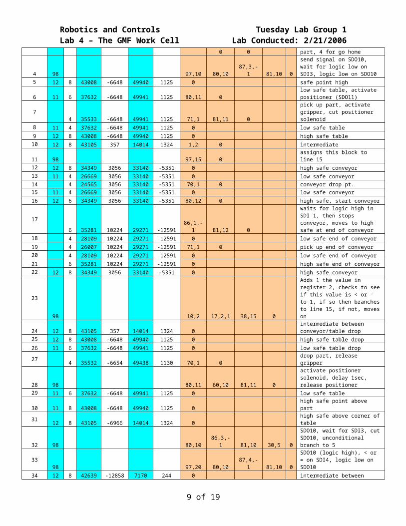
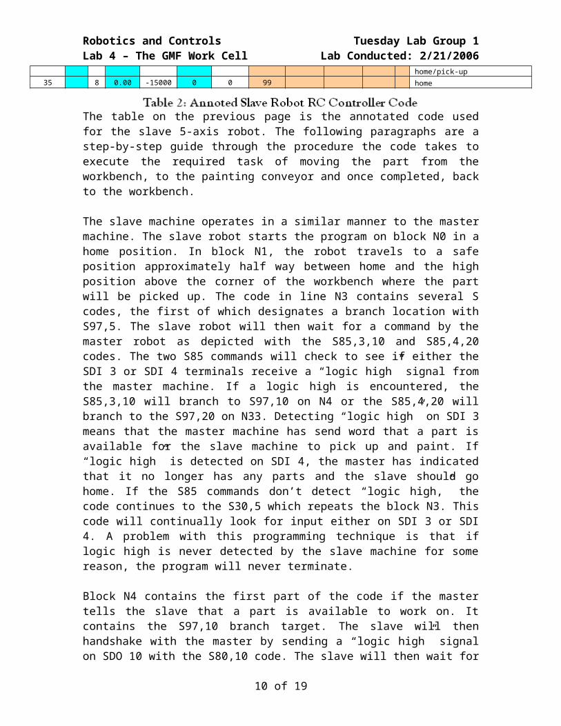
Robotics and Controls Tuesday Lab Group 1Lab 4 – The GMF Work Cell Lab Conducted: 2/21/2006The table on the previous page is the annotated code used for the slave 5-axis robot. The following paragraphs are a step-by-step guide through the procedure the code takes to execute the required task of moving the part from the workbench, to the painting conveyor and once completed, back to the workbench.
The slave machine operates in a similar manner to the master machine. The slave robot starts the program on block N0 in a home position. In block N1, the robot travels to a safe position approximately half way between home and the high position above the corner of the workbench where the part will be picked up. The code in line N3 contains several S codes, the first of which designates a branch location with S97,5. The slave robot will then wait for a command by the master robot as depicted with the S85,3,10 and S85,4,20 codes. The two S85 commands will check to see if either the SDI 3 or SDI 4 terminals receive a “logic high” signal from the master machine. If a logic high is encountered, the S85,3,10 will branch to S97,10 on N4 or the S85,4,20 will branch to the S97,20 on N33. Detecting “logic high” on SDI 3 means that the master machine has send word that a part is available for the slave machine to pick up and paint. If “logic high” is detected on SDI 4, the master has indicated that it no longer has any parts and the slave should go home. If the S85 commands don’t detect “logic high,” the code continues to the S30,5 which repeats the block N3. This code will continually look for input either on SDI 3 or SDI 4. A problem with this programming technique is that if logic high is never detected by the slave machine for some reason, the program will never terminate.
Block N4 contains the first part of the code if the master tells the slave that a part is available to work on. It contains the S97,10 branch target. The slave will then handshake with the master by sending a “logic high” signal on SDO 10 with the S80,10 code. The slave will then wait for the master to acknowledge by looking for “logic low” on SDI 3. Once this has been completed, the slave machine will turn off SDO 10 and continue with getting the part.
The slave machine will move to a high safe point above the part in block N5, and then to a low safe point in block N6. Also in block N6, the SDO 11 will be turned on to activate the solenoid valve controlling the pneumatic positioner. This positioner will push the part into a 3-pin jig to accurately locate it for picking up. The slave robot will then move down to the part and activate the gripper in block N7 with an S71,1 code. Also the SDO 11 will be turned off to release the positioner.
Now that the slave machine has control of the part, it will move to through the low safe and high safe positions above the workbench in blocks N8 and N9, respectively, and to an intermediate position between the workbench and the conveyor in block N10. Block N10 also contains S1,2 which clears, or sets a value of zero, to register number 2. This register will be used in a loop to control the number of times the part gets “painted.” Block N11 assigns a branch locater of S97,15. This locater is placed at this point in the code to return the robot if an additional coat of paint is required on the part.
The robot will move to a high safe position above the painting conveyor in block N12, and then to a low safe in block N13. Block N14 will place the part on the conveyor and release the gripper with an S70,1 command. The robot will then move to the low safe
7 of 12
Robotics and Controls Tuesday Lab Group 1Lab 4 – The GMF Work Cell Lab Conducted: 2/21/2006above the starting end of the conveyor in block N15, and then to the high safe position in block N16. Also in block N16, the conveyor is activated with an S80,12 code. The robot will then move to a high position at the opposite, or unloading, end of the conveyor in N17. Also, N17 contains S86,1,-1 which will wait for a part to be seen at the end of the conveyor by the photo cell. Once a “logic high” has been read on SDI 1, meaning the part has reached the end of the conveyor, the code continues with S81,12, which will turn off the conveyor. The slave robot will then move to a low safe position at the end of the conveyor in block N18, and pick up the part in block N19 using S71,1. The robot will then move back to the low safe position, the high safe position at the end of the conveyor, and then the high safe position at the start of the conveyor in blocks N20, N21, and N22, respectively. Block N23 will now check to see how many times the part has been painted. An S10,2 is executed, which will increment the value of register 2 by one. Next, an S17,2,1 will compare the value of register 2 to the value 1 and set a flag of <, >, or =. If the flag set is < or =, the code will branch to S97,15 on N11 and paint the part again. This is accomplished by using an S38,15 code. Otherwise, when the part has been painted twice the code will continue by bringing the part back to the workbench.
The part will then be placed back on the workbench in blocks N24, N25, N26, and N27. Block N24 is a position above the corner of the workbench. This position is also the wait position for the slave robot while the master has control of the part. Block N25 is the high safe position above the drop point on the workbench, and N26 is the low safe point. The part is released in block N27 with an S70,1 code. The positioner is activated in block N28 to reestablish an accurate location for the part. This is done by an S80,11 command, a delay of one second using S60,10, and then the release of the positioner with S81,11.
Now that the part is placed back on the workbench, the slave robot moves to the low safe position in block N29, the high safe position in N30, and then the wait position in N31 above the corner of the workbench. The slave will then tell the master that it has completed its portion of the operation by sending “logic high” with an S80,10 code. The slave will wait for acknowledgement from the master with S86,3,-1. Once this has occurred, the slave will turn off SDO 10 and branch back to S97,5 on block N3. Now the slave is back in position to wait for further instructions from the master robot.
If the slave is told to go home by the master, the code branches to S97,20 on N33. The slave will acknowledge this command by turning on SDO 10. It will then wait for a response with S87,4,-1. Once the master has sent its “logic low” signal, the slave will turn off SDO 10 and continue home. The robot will then move to an intermediate position on the way home in block N34, and finally to the home position in block N35. Here, an S99 is executed to end the program.
WIRING THE WORK CELL
There are three main components to the wiring of the entire work cell. The first two, which are the wiring of the turn table to the master robot and the conveyor to the slave robot, are quite similar. The third component is the wiring which establishes the
8 of 12
Robotics and Controls Tuesday Lab Group 1Lab 4 – The GMF Work Cell Lab Conducted: 2/21/2006interaction and communication between the two robots. The following schematic, seen in
Figure 3, will help visualize the wiring of the robots.
9 of 12
Robotics and Controls Tuesday Lab Group 1Lab 4 – The GMF Work Cell Lab Conducted: 2/21/2006
For the connection between the master and turn table, a photo eye, or photo cell, is used which has three wires coming out of it: blue, brown, and black. The blue wire is connected to pin 2 on the Relay 2, which is also connected to the ground terminal on the master SDI/SDO terminal. The brown wire is connected to pin 7 on the right relay, which is essentially connected to the master 24V through pin 2 on the Relay 1. When the photo eye receives light signal back into its sensor (indicating that a part is in front of it), it applies 24V to the black wire connected to pin 10 on the right relay. This effectively puts 24V across the coil connecting pins 2 and 10, which creates an electromagnetic field. This electromagnetic field throws the switch from normally closed (pin 5/6) to normally open (pin 6/7). This allows the 24V in pin 7 to flow through pin 6 and into input 8 on the SDI. The system then makes a comparison with the input voltage and a ground state. If this voltage difference is above three volts, the system creates a “logic high” state. Otherwise, if there is no voltage, the state is “logic low.”
Performing an S80 code allows the master SDO 10 terminal to connect to ground. This means that pin 10 on the Relay 1 is grounded and there is 24V on pin 2, creating an electromagnetic field in the Relay 1 coil. This has the same effect, causing the switch to throw to normally open (pins 6/7), effectively switching on the motor driving the table, or conveyor. When an S81 code is applied, the SDO 10 opens the circuit and the field drops, throwing the switch back to pins 5 and 6, opening the motor circuit, turning it off.
Similarly, the slave machine uses relays and SDI/SDO terminals to control the conveyor. When an S80,12 command is executed, this causes the slave output terminal 12 to connect to ground. This terminal is connected to pin 2 on Relay 8. Seeing as pin 10 on Relay 8 is connected to the slave 24V source, the coil in Relay 8 is activated. This electromagnetic field throws the switch from normally closed to normally open (pin 6/7), which activates the motor for the conveyor. When the coil is disconnected by an S81,12 command connecting the slave SDO 12 to ground, the switch returns to normally closed (pin 5/6 and pin 1/4). This normally closed position completes the AC circuit through pins 1 and 4 to apply power to the brake in the conveyor motor.
The same principle is used with the photocell on the slave robot as it is in the master robot. When the photocell detects a part on the conveyor, 24V is applied through the black wire on the photocell into pin 10 on Relay 7. This will generate the electromagnetic field in the Relay 7 coil because pin 2 is connected to the slave ground through pin 5. When the coil is active, the switch throws from normally closed (pin 5/6) to normally open (pin 6/7). This connects the slave SDI 1, which is wired to pin 6, to the slave 24V wired to pin 7. This 24V on SDI 1 will cause the robot control to read a “logic high” state. When the coil is inactive, the ground state will be seen through pin 5/6 on SDI 1, creating a “logic low” condition.
Once the part is placed on the table by the master robot and ready to be picked up by the slave robot, the part is pushed into a 3-pin jig for location by a pneumatic piston actuated
10 of 12
Robotics and Controls Tuesday Lab Group 1Lab 4 – The GMF Work Cell Lab Conducted: 2/21/2006by a solenoid valve. The solenoid is “powered” by Relay 3. Pin 2 on Relay 3 is connected to the slave SDO 11, which when S80,11 is called, will connect to ground. This causes the coil from pin 2 to pin 7 to activate because pin 7 is wired to the slave 24V source. This coil throws the switch from normally closed (pin 1/4) to normally open (pin 1/3). This causes the 24V in pin 3 to go through pin 1 to the black wire of the solenoid. The silver wire of the solenoid is then connected to ground through pin 4 on Relay 3. This solenoid controls a valve which allows air to push a pneumatic piston, essentially locating the part on the jig.
The communication or handshaking between the two robots is accomplished by the last three relays. Within the communication between the two robots, there are three main “phrases” exchanged, including the master telling the slave that a part is available for painting, the master telling the slave to go home after no parts have been encountered on the turn table, and basic acknowledgement between the two.
For the indication from the master that a part is available, the master robot connects SDO 5 to ground, which activates the coil in Relay 5. When the coil is active, the switch throws from normally closed (pin 1/4) to normally open (pin 1/3). This allows the 24V on pin 3 to go through pin 1 and into the slave SDI 3. Now the slave reads “logic high” on SDI 3. When the coil is inactive, pin 1 is connected through pin 4 to ground and the slave reads “logic low” on SDI 3.
When the master tells the slave to go home, the master SDO 6 is connected to ground, activating the coil in Relay 6 since pin 10 is connected to 24V. This throws the switch from normally closed (pin 5/6) to normally open (pin 6/7). This allows the 24V on pin 7 to flow through the switch to pin 6 and into the slave SDI 4. Now the slave reads “logic high” on SDI 4. When the coil is inactive, pin 6 is connected through pin 5 to ground and the slave reads “logic low” on SDI 4.
The acknowledgement from the slave to the master takes place with Relay 4. When the slave robot connects SDO 10 to ground, the 24V across pins A and B activates the coil in the relay. This throws the switch from normally closed (pin 9/3) to normally open (pin 9/6). As in Relay 5 and Relay 6, this allows the 24V at pin 6 to flow through pin 9 to the master SDI 10. The master now reads “logic high” on SDI 10.
The “handshaking” technique involves the master telling the slave a statement, either that a part is available or to go home. Then the slave machine sends acknowledgement back on SDI 10 with “logic high”. Then the master will confirm the acknowledgement by turning off the SDO terminal and then wait for a confirmation of that on SDI 10. The slave will turn off SDO 10, making the master SDI 10 read “logic low.” This is the basic concept of the handshaking in this work cell.
Conclusion
Although the code ran smoothly in the end, there were a few problems encountered at the initial execution of the code. The first error found involved the pose control of the 4-axis
11 of 12
Robotics and Controls Tuesday Lab Group 1Lab 4 – The GMF Work Cell Lab Conducted: 2/21/2006master robot. Once the part had been painted by the 5-axis slave robot and was placed on the workbench, the 4-axis was programmed with the incorrect safe point locations. In turn, the part was dragged across the workbench in such a manner that its orientation was changed within the robot’s vacuum grip and could not be placed properly back onto the rotating table. This problem was easily fixed by changing the movement between the pickup point and lower safe point.
One of the other problems encountered involved a miscommunication error between the master and slave robots. Towards the end of the program execution, when the rotating table had no parts on it, the master sent a “go home” command to the slave and waited for a reply from the slave robot. The slave in turn received the “go home” command and proceeded to its home location without sending a reply signal back to the master. This caused the master to sit in the waiting position for an infinite amount of time.
Another good procedure that should be incorporated in code is to keep the consistency of robot movements the same when it repeatedly moving from point to point. For example, a few times within the code the master robot did not move away from the drop off point on the work bench in the same manner every time. This made the code slightly difficult to follow. If the robot had always moved from the midpoint, to safe high, to safe low, to the drop off, and then moved away in the same exact manner as it came in, the code could have been more easily understood. Occasionally a new midpoint was used between the rotating table and work bench which made reading the code more difficult.
This code, although being relatively efficient has room for more improvement. If possible it would be nice to have multiple work pieces moving through the system at the same time. This would allow for both robots to be continually working on a task instead of waiting idly for another part to appear on the work bench. Also, there perhaps could be a way to have multiple drop locations on the work bench if there may be a large flow of parts into the work cell. By combining the interaction of the two robots as well as the turn table and conveyor through the use of the SDI/SDO terminals, the work cell was easily programmed for an automated process. This lab provided a perfect example of how robots can be programmed to perform simple tasks.