MDE-4199 Contactless Smart Card Retrofit Kit M05205K00X Installation Manual • January 2005 Page 1 Introduction Table of Contents Purpose This manual provides installation instructions for the M05205K00X Contactless Smart Card Retrofit Kits. These kits are used in the following units: The Contactless Smart Card Reader operates on an RF signal received by the antenna located behind the target on the CRIND graphics overlay. This provides customers with the capability of having their card read by simply passing the card within 2-inches of the target graphic with either of the flat sides of the card facing the logo. Note: This feature requires that the dispenser subject to installation contain the card reader option. Door replacement may be required for The Advantage Series dispensers that contain aluminum CRIND doors or pre-ADA doors. Topic Page "Introduction" Page 1 "Table of Contents" Page 1 "Purpose" Page 1 "Required Reading" Page 2 "Related Documents" Page 2 "Required Tools" Page 2 "Parts Lists" Page 3 "Important Safety Information" Page 5 "Installation" Page 7 "Installing M05205K001 Kit in an Encore Unit" Page 7 "Installing M05205K002 Kit in an Eclipse Unit" Page 12 "Installing M05205K003 Kit in The Advantage Series Unit W/O Cash Acceptor" Page 18 "Installing M05205K004 Kit in The Advantage Series Unit With Cash Acceptor" Page 26 Type Unit Kit Number The Encore ® units (Double Sided) M05205K001 The Eclipse ® Units (Double Sided) M05205K002 The Advantage ® Series dispenser with InfoScreen ® and monochrome Card Reader In Dispenser (CRIND ® ) features. M05205K003 The Advantage Series dispensers that contain the original Single-Line CRIND or American Disability Act (ADA) doors. M05205K004 MDE-4199 Contactless Smart Card Retrofit Kit M05205K00X Installation Manual January 2005
Transcript
MDE-4199Contactless Smart Card Retrofit Kit
M05205K00X Installation ManualJanuary 2005
Introduction
Table of Contents
PurposeThis manual provides installation instructions for the M05205K00X Contactless Smart Card Retrofit Kits. These kits are used in the following units:
The Contactless Smart Card Reader operates on an RF signal received by the antenna located behind the target on the CRIND graphics overlay. This provides customers with the capability of having their card read by simply passing the card within 2-inches of the target graphic with either of the flat sides of the card facing the logo.Note: This feature requires that the dispenser subject to installation contain the card reader
option. Door replacement may be required for The Advantage Series dispensers that contain aluminum CRIND doors or pre-ADA doors.
Topic Page
"Introduction" Page 1
"Table of Contents" Page 1
"Purpose" Page 1
"Required Reading" Page 2
"Related Documents" Page 2
"Required Tools" Page 2
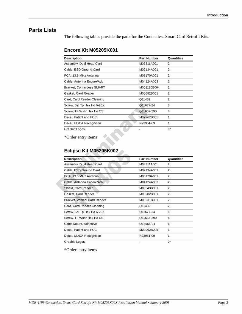
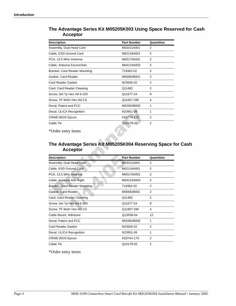
"Parts Lists" Page 3
"Important Safety Information" Page 5
"Installation" Page 7
"Installing M05205K001 Kit in an Encore Unit" Page 7
"Installing M05205K002 Kit in an Eclipse Unit" Page 12
"Installing M05205K003 Kit in The Advantage Series Unit W/O Cash Acceptor" Page 18
"Installing M05205K004 Kit in The Advantage Series Unit With Cash Acceptor" Page 26
Type Unit Kit Number
The Encore® units (Double Sided) M05205K001
The Eclipse® Units (Double Sided) M05205K002
The Advantage® Series dispenser with InfoScreen® and monochrome Card Reader In Dispenser (CRIND®) features.
M05205K003
The Advantage Series dispensers that contain the original Single-Line CRIND or American Disability Act (ADA) doors.
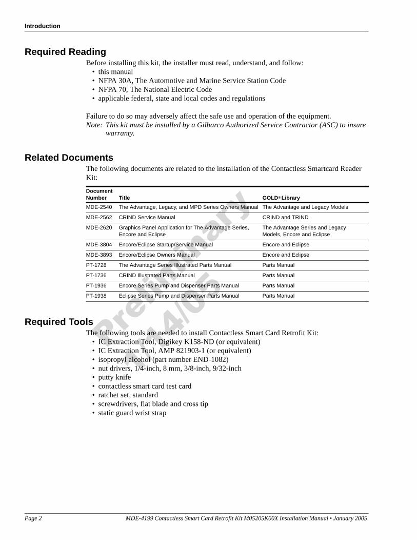
Required ReadingBefore installing this kit, the installer must read, understand, and follow:
• this manual• NFPA 30A, The Automotive and Marine Service Station Code• NFPA 70, The National Electric Code• applicable federal, state and local codes and regulations
Failure to do so may adversely affect the safe use and operation of the equipment.Note: This kit must be installed by a Gilbarco Authorized Service Contractor (ASC) to insure
warranty.
Related DocumentsThe following documents are related to the installation of the Contactless Smartcard Reader Kit:
Required ToolsThe following tools are needed to install Contactless Smart Card Retrofit Kit:
• IC Extraction Tool, Digikey K158-ND (or equivalent)• IC Extraction Tool, AMP 821903-1 (or equivalent)• isopropyl alcohol (part number END-1082)• nut drivers, 1/4-inch, 8 mm, 3/8-inch, 9/32-inch• putty knife• contactless smart card test card• ratchet set, standard• screwdrivers, flat blade and cross tip• static guard wrist strap
Document Number Title GOLD® Library
MDE-2540 The Advantage, Legacy, and MPD Series Owners Manual The Advantage and Legacy Models
MDE-2562 CRIND Service Manual CRIND and TRIND
MDE-2620 Graphics Panel Application for The Advantage Series, Encore and Eclipse
The Advantage Series and Legacy Models, Encore and Eclipse
MDE-3804 Encore/Eclipse Startup/Service Manual Encore and Eclipse
MDE-3893 Encore/Eclipse Owners Manual Encore and Eclipse
PT-1728 The Advantage Series Illustrated Parts Manual Parts Manual
PT-1736 CRIND Illustrated Parts Manual Parts Manual
PT-1936 Encore Series Pump and Dispenser Parts Manual Parts Manual
PT-1938 Eclipse Series Pump and Dispenser Parts Manual Parts Manual
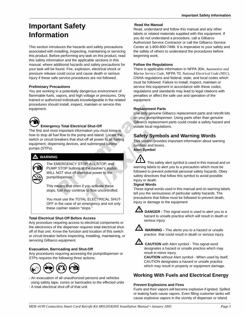
This section introduces the hazards and safety precautions associated with installing, inspecting, maintaining or servicing this product. Before performing any task on this product, read this safety information and the applicable sections in this manual, where additional hazards and safety precautions for your task will be found. Fire, explosion, electrical shock or pressure release could occur and cause death or serious injury if these safe service procedures are not followed.
Preliminary PrecautionsYou are working in a potentially dangerous environment of flammable fuels, vapors, and high voltage or pressures. Only trained or authorized individuals knowledgeable in the related procedures should install, inspect, maintain or service this equipment.
Emergency Total Electrical Shut-OffThe first and most important information you must know is how to stop all fuel flow to the pump and island. Locate the switch or circuit breakers that shut-off all power to all fueling equipment, dispensing devices, and submerged turbine pumps (STPs).
Total Electrical Shut-Off Before AccessAny procedure requiring access to electrical components or the electronics of the dispenser requires total electrical shut-off of that unit. Know the function and location of this switch or circuit breaker before inspecting, installing, maintaining, or servicing Gilbarco equipment.
Evacuation, Barricading and Shut-OffAny procedures requiring accessing the pump/dispenser or STPs requires the following three actions:
- An evacuation of all unauthorized persons and vehicles using safety tape, cones or barricades to the effected units- A total electrical shut-off of that unit
Read the ManualRead, understand and follow this manual and any other labels or related materials supplied with this equipment. If you do not understand a procedure, call a Gilbarco Authorized Service Contractor or call the Gilbarco Service Center at 1-800-800-7498. It is imperative to your safety and the safety of others to understand the procedures before beginning work.
Follow the RegulationsThere is applicable information in NFPA 30A; Automotive and Marine Service Code, NFPA 70; National Electrical Code (NEC), OSHA regulations and federal, state, and local codes which must be followed. Failure to install, inspect, maintain or service this equipment in accordance with these codes, regulations and standards may lead to legal citations with penalties or affect the safe use and operation of the equipment.
Replacement PartsUse only genuine Gilbarco replacement parts and retrofit kits on your pump/dispenser. Using parts other than genuine Gilbarco replacement parts could create a safety hazard and violate local regulations.
Safety Symbols and Warning WordsThis section provides important information about warning symbols and boxes.Alert Symbol
This safety alert symbol is used in this manual and on warning labels to alert you to a precaution which must be followed to prevent potential personal safety hazards. Obey safety directives that follow this symbol to avoid possible injury or death.Signal WordsThese signal words used in this manual and on warning labels tell you the seriousness of particular safety hazards. The precautions that follow must be followed to prevent death, injury or damage to the equipment
DANGER - This signal word is used to alert you to a hazard to unsafe practice which will result in death or serious injury
WARNING - This alerts you to a hazard or unsafe practice that could result in death or serious injury.
CAUTION with Alert symbol - This signal word designates a hazard or unsafe practice which may result in minor injury.CAUTION without Alert symbol - When used by itself, CAUTION designates a hazard or unsafe practice which may result in property or equipment damage.
Working With Fuels and Electrical Energy
Prevent Explosions and FiresFuels and their vapors will become explosive if ignited. Spilled or leaking fuels cause vapors. Even filling customer tanks will cause explosive vapors in the vicinity of dispenser or island.
The EMERGENCY STOP, ALL STOP, and PUMP STOP buttons at the cashier’s station WILL NOT shut off electrical power to the pump/dispenser.
This means that even if you activate these stops, fuel may continue to flow uncontrolled.
You must use the TOTAL ELECTRICAL SHUT-OFF in the case of an emergency and not only these cashier station “stops.”
Open flames from matches, lighters, welding torches or other sources can ignite fuels and their vapors.No Sparks - No Smoking
Sparks from starting vehicles, starting or using power tools, burning cigarettes, cigars or pipes can also ignite fuels and their vapors. Static electricity, including an electrostatic charge on your body, can cause a spark sufficient to ignite fuels and their vapors. After getting out of a vehicle, touch the metal of your vehicle to discharge any electrostatic charge before you approach the dispenser island.
Working AloneIt is highly recommended that someone who is capable of rendering first aid be present during servicing. Be familiar with Cardiopulmonary Resuscitation (CPR) methods if you are working with or around high voltages. This information is available from the American Red Cross. Always advise the station personnel about where you will be working, and caution them not to activate power while you are working on the equipment. Use the OSHA tag out and lock out procedures. If you are not familiar with this requirement, refer to information in the service manual and OSHA documentation.
Working With Electricity SafelyBe sure to use safe and established practices in working with electrical devices. Poorly wired devices may cause a fire, explosion or electrical shock. Be sure grounding connections are properly made. Make sure that sealing devices and compounds are in place. Be sure not to pinch wires when replacing covers Follow OSHA Lock-Out and Tag-Out requirements. Station employees and service contractors need to understand and comply with this program completely to ensure safety while the equipment is down.
Hazardous MaterialsSome materials present inside electronic enclosures may present a health hazard if not handled correctly. Be sure to clean hands after handling equipment. Do not place any equipment in mouth.
IMPORTANT: Oxygen may be needed at scene if gasoline has been ingested or inhaled. Seek medical advice immediately.
Emergency First Aid
Informing Emergency PersonnelCompile the following information for emergency personnel:Location of accident (for example, address, front/back of building, and so on.)Nature of accident (for example, possible heart attack, run over by car, burns, and so on.)Age of victim (for example, baby, teenager, middle-age, elderly)Whether or not victim has received first aid (for example, stopped bleeding by pressure, and so on.)Whether or not a victim has vomited (for example, if swallowed or inhaled something, and so on.)
IMPORTANT: Oxygen may be needed at scene if gasoline has been ingested or inhaled. Seek medical advice immediately.
Lockout/TagoutLockout/Tagout covers servicing and maintenance of Machines and equipment in which unexpected energizing or start up of the machine(s) or equipment or release of stored energy could cause injury to employees or personnel. Lockout/Tagout applies to all mechanical, hydraulic, chemical or other energy, but does not cover electrical hazards. Reference Subpart S of 29 CFR Part 1910 - Electrical Hazards, 29 CFR Part 1910.333 contains specific Lockout/Tagout provision for electrical hazards.
This area contains a chemical known to the State of California to cause cancer.
WARNING!
This area contains a chemical known to the State of California to cause birth defects or other reproductive harm.
WARNING!
Gasoline ingested may cause unconsciousness and burns to internal organs.Do not induce vomiting.Keep airway open. Oxygen may be needed at scene.Seek medical advice immediately.
WARNING!
Gasoline inhaled may cause unconsciousness and burns to lips, mouth and lungs.Keep airway open.Seek medical advice immediately.
WARNING!
Gasoline spilled in eyes may cause burns to eye tissue.Irrigate eyes with water for approximately 15 minutes.Seek medical advice immediately
WARNING!
Gasoline spilled on skin may cause burns.Wash area thoroughly with clear/water.Seek medical advice immediately.
Installing M05205K001 Kit in an Encore UnitThe M05205K001 Kit contains parts for both side 1 and side 2 of the Encore Unit. Therefore, all procedures performed on Side 1 of the unit must also be performed on Side 2.
Removing the Card Reader from the Encore UnitWhen installing a contactless smart card kit, the existing card reader must be removed and replaced with a dual head card assembly (part of the kit).
Remove the existing card reader as follows:
1 Read all instructions before beginning and observe all safety precautions during installation.
2 Obtain approval from store manager or responsible personnel to remove unit from service.
3 Remove AC power to the unit using the station circuit breaker. Refer to MDE-3893 Encore/Eclipse Owners Manual for details on removing system power.
4 Locate the Customer Interface Module (CIM) door, insert the key, and open the door.
5 Repeat Step 3 for side 2 of the unit.
6 From the rear of the CIM Door disconnect the cable harness or ribbon cable connection (Figure 1) connected to the card reader.
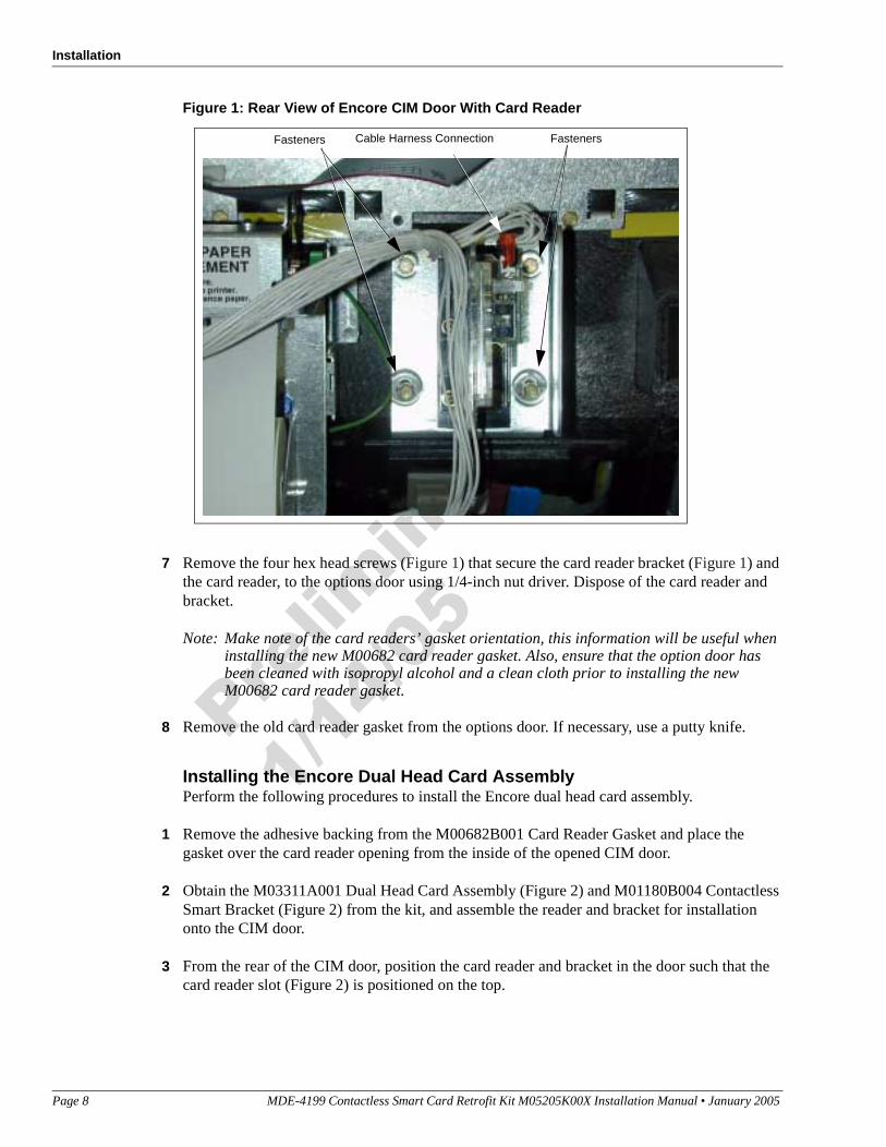
Figure 1: Rear View of Encore CIM Door With Card Reader
7 Remove the four hex head screws (Figure 1) that secure the card reader bracket (Figure 1) and the card reader, to the options door using 1/4-inch nut driver. Dispose of the card reader and bracket.
Note: Make note of the card readers’ gasket orientation, this information will be useful when installing the new M00682 card reader gasket. Also, ensure that the option door has been cleaned with isopropyl alcohol and a clean cloth prior to installing the new M00682 card reader gasket.
8 Remove the old card reader gasket from the options door. If necessary, use a putty knife.
Installing the Encore Dual Head Card AssemblyPerform the following procedures to install the Encore dual head card assembly.
1 Remove the adhesive backing from the M00682B001 Card Reader Gasket and place the gasket over the card reader opening from the inside of the opened CIM door.
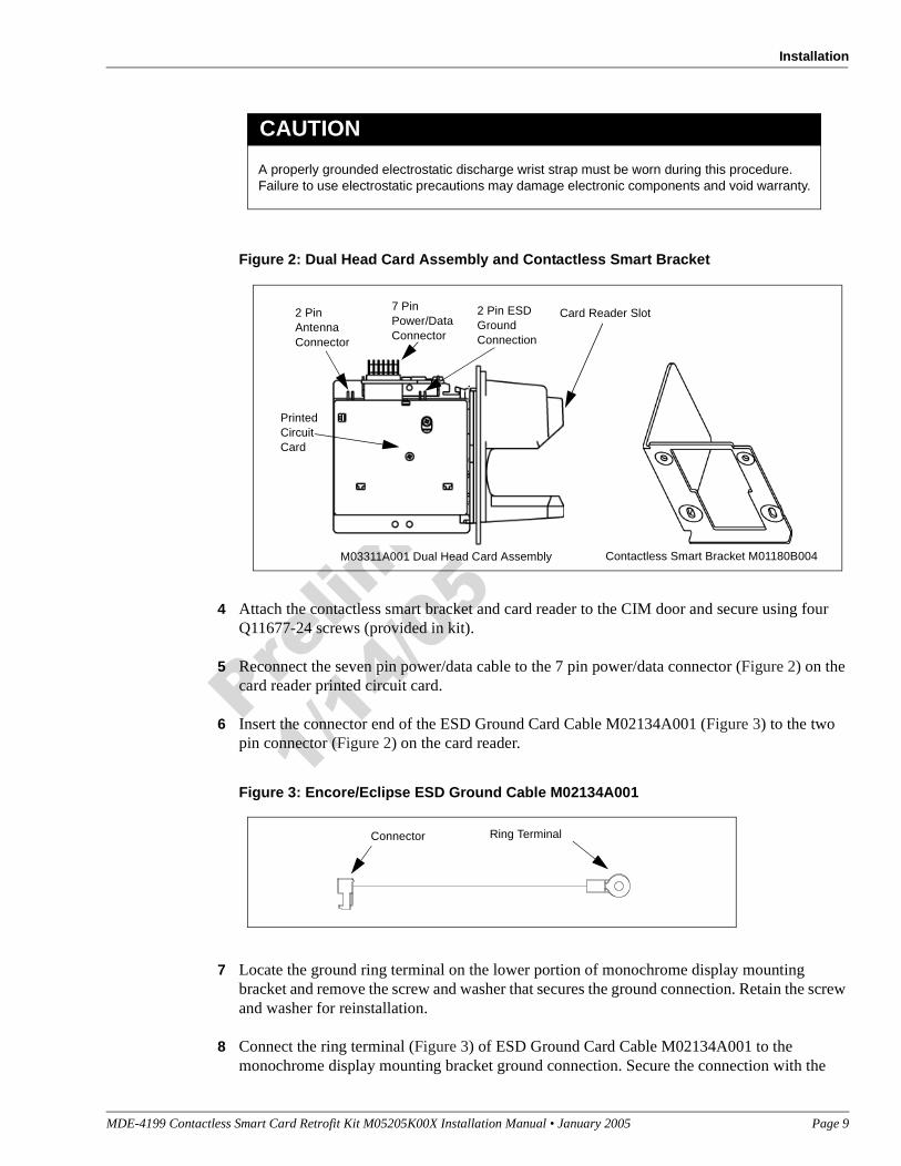
2 Obtain the M03311A001 Dual Head Card Assembly (Figure 2) and M01180B004 Contactless Smart Bracket (Figure 2) from the kit, and assemble the reader and bracket for installation onto the CIM door.
3 From the rear of the CIM door, position the card reader and bracket in the door such that the card reader slot (Figure 2) is positioned on the top.
7 Locate the ground ring terminal on the lower portion of monochrome display mounting bracket and remove the screw and washer that secures the ground connection. Retain the screw and washer for reinstallation.
8 Connect the ring terminal (Figure 3) of ESD Ground Card Cable M02134A001 to the monochrome display mounting bracket ground connection. Secure the connection with the
A properly grounded electrostatic discharge wrist strap must be worn during this procedure. Failure to use electrostatic precautions may damage electronic components and void warranty.
CAUTION
Card Reader Slot
M03311A001 Dual Head Card Assembly Contactless Smart Bracket M01180B004
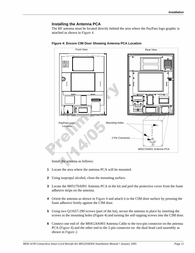
Installing the Antenna PCAThe RF antenna must be located directly behind the area where the PayPass logo graphic is attached as shown in Figure 4.
Figure 4: Encore CIM Door Showing Antenna PCA Location
Install the antenna as follows:
1 Locate the area where the antenna PCA will be mounted.
2 Using isopropyl alcohol, clean the mounting surface.
3 Locate the M05170A001 Antenna PCA in the kit and peel the protective cover from the foam adhesive strips on the antenna.
4 Orient the antenna as shown in Figure 4 and attach it to the CIM door surface by pressing the foam adhesive firmly against the CIM door.
5 Using two Q11657-290 screws (part of the kit), secure the antenna in place by inserting the screws in the mounting holes (Figure 4) and turning the self-tapping screws into the CIM door.
6 Connect one end of the M04124A003 Antenna Cable to the two-pin connector on the antenna PCA (Figure 4) and the other end to the 2-pin connector on the dual head card assembly as shown in Figure 2.
Completing Installation for the Encore UnitsPerform the following steps to complete installation.
1 Close and secure the main doors.
2 Close and secure the CIM Doors
3 Install the appropriate graphics.
4 Restore power to unit. Refer to MDE-3893 Encore/Eclipse Owners Manual.
5 Upgrade the CRIND BIOS using the Laptop Tool Software. See MDE-3921 for complete instructions on loading the Laptop Tool Software.
6 Test the RF Readers by sliding CRIND Diagnostic Card Q12534 through both readers the with the magnetic strip up.
7 Verify that a valid read was made from the diagnostic card.
8 Pass the Contactless Smartcard test card in front of the RF antenna (flat side toward antenna).
9 Verify that a valid read was made from the test card.
10 Apply appropriate graphic logos. These are order entry items. See MDE-2620 for graphic application instructions.
Installing M05205K002 Kit in an Eclipse UnitThe M05205K002 Kit contains parts for both side 1 and side 2 of the Eclipse Unit. Therefore, all procedures performed on Side 1 of the unit must also be performed on Side 2.
Installation of the PayPass RF Reader Kit M02139K002 for the Eclipse units involves performing the following categories of installation:
• “Preparing for Installation” on page 12• “Removing the Eclipse Existing Card Reader” on page 14• “Installing the Eclipse Dual Head Card Assembly” on page 15• “Installing the Antenna PCA” on page 17• “Completing Installation for the Eclipse Units” on page 17.
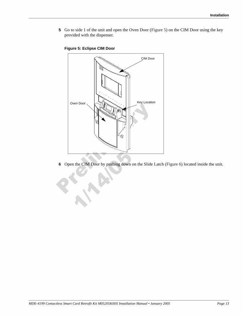
Preparing for InstallationPerform the following steps to prepare for the installation of PayPass RF Reader Kit M02139K002 for an Eclipse unit.
1 Read all instructions before beginning.
2 Observe all safety precautions.
3 Obtain approval from store manager or responsible personnel to remove unit from service.
4 Remove power from the fuelling unit. Refer to MDE-3804 Encore and Eclipse Series Start-Up/Service Manual.
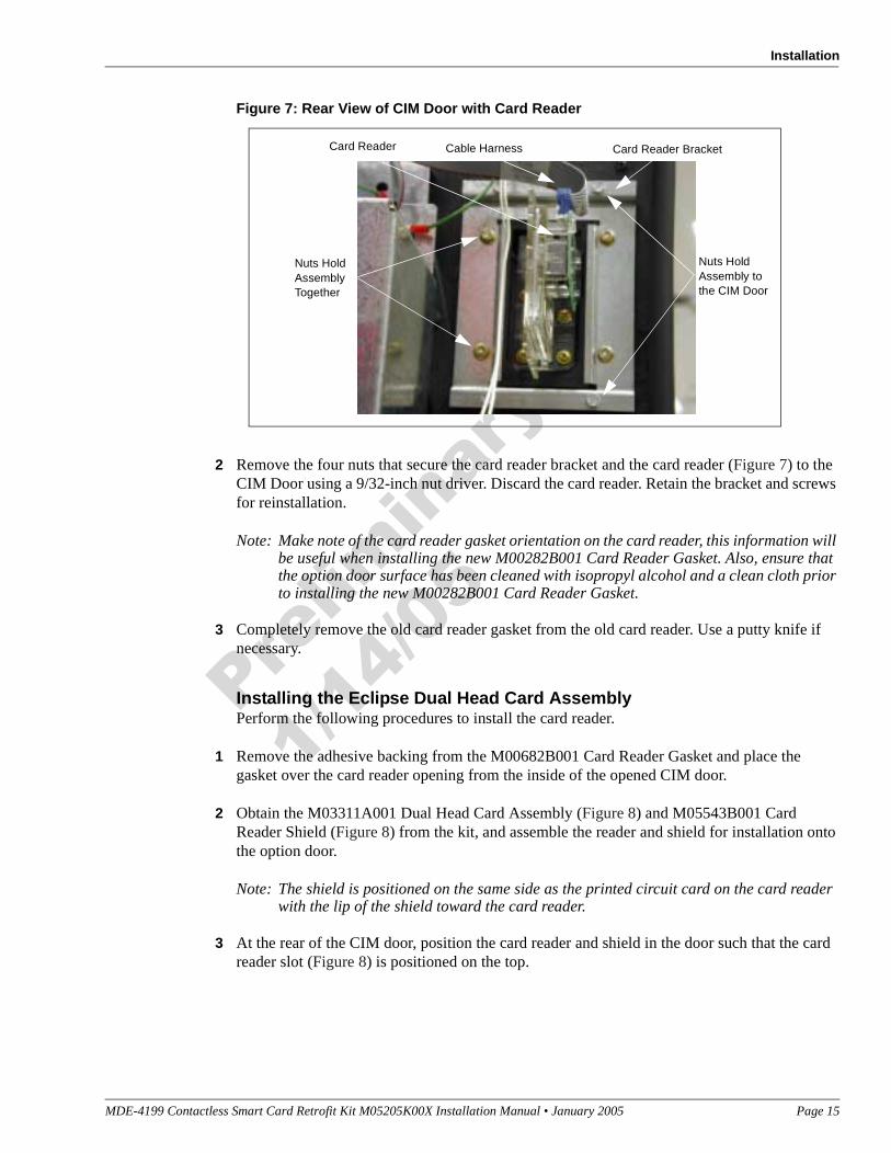
2 Remove the four nuts that secure the card reader bracket and the card reader (Figure 7) to the CIM Door using a 9/32-inch nut driver. Discard the card reader. Retain the bracket and screws for reinstallation.
Note: Make note of the card reader gasket orientation on the card reader, this information will be useful when installing the new M00282B001 Card Reader Gasket. Also, ensure that the option door surface has been cleaned with isopropyl alcohol and a clean cloth prior to installing the new M00282B001 Card Reader Gasket.
3 Completely remove the old card reader gasket from the old card reader. Use a putty knife if necessary.
Installing the Eclipse Dual Head Card AssemblyPerform the following procedures to install the card reader.
1 Remove the adhesive backing from the M00682B001 Card Reader Gasket and place the gasket over the card reader opening from the inside of the opened CIM door.
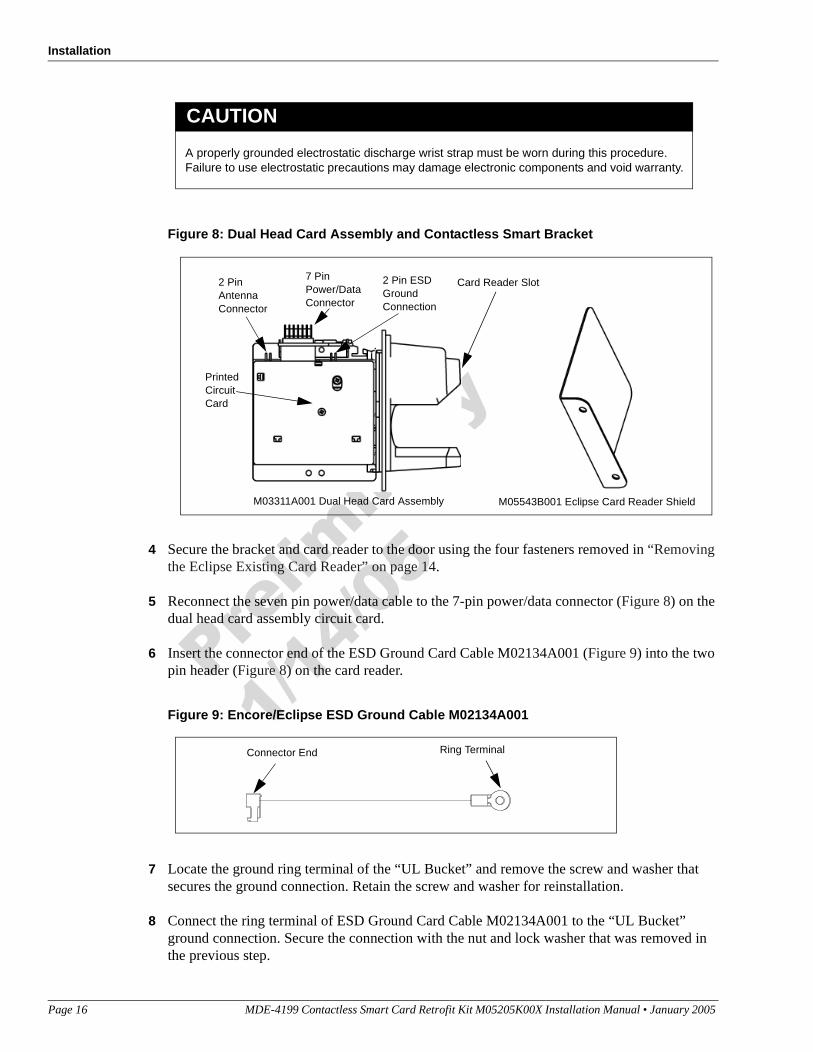
2 Obtain the M03311A001 Dual Head Card Assembly (Figure 8) and M05543B001 Card Reader Shield (Figure 8) from the kit, and assemble the reader and shield for installation onto the option door.
Note: The shield is positioned on the same side as the printed circuit card on the card reader with the lip of the shield toward the card reader.
3 At the rear of the CIM door, position the card reader and shield in the door such that the card reader slot (Figure 8) is positioned on the top.
7 Locate the ground ring terminal of the “UL Bucket” and remove the screw and washer that secures the ground connection. Retain the screw and washer for reinstallation.
8 Connect the ring terminal of ESD Ground Card Cable M02134A001 to the “UL Bucket” ground connection. Secure the connection with the nut and lock washer that was removed in the previous step.
A properly grounded electrostatic discharge wrist strap must be worn during this procedure. Failure to use electrostatic precautions may damage electronic components and void warranty.
CAUTION
Card Reader Slot
M03311A001 Dual Head Card Assembly M05543B001 Eclipse Card Reader Shield
9 Ensure that the all Ground Cables are secured to the unit with sufficient slack to prevent cable pulls and pinching.
Installing the Antenna PCAThe RF antenna must be located directly behind the area where the logo graphic is attached. Looking at the back of the oven door, the antenna will be located on the right side just above the center of the door (to the right of the keypad).
Install the antenna as follows:
1 Locate the area where the RF antenna will be mounted.
2 Using isopropyl alcohol, clean the mounting surface.
3 Locate the M05170A001 Antenna PCA in the kit and peel the protective cover from the foam adhesive strips on the antenna.
4 Position the antenna on the back of the oven door to the right and just above the center of the door (to the right of the keypad) and attach it to the door surface by pressing the foam adhesive firmly to the door.
5 Using two Q11657-290 screws (part of the kit), secure the antenna in place by inserting the screws in the mounting holes and turning the self-tapping screws into the oven door.
6 Connect one end of the M04124A002 Antenna Cable to the two-pin connector on the antenna PCA and the other end to the 2-pin connector on the dual head card assembly shown in Figure 8.
Completing Installation for the Eclipse UnitsPerform the following steps to complete installation.
1 Close and secure the Oven and CIM doors.
2 Install the appropriate graphics.
3 Restore power to unit. Refer to MDE-3893 Encore/Eclipse Owners Manual.
4 Upgrade the CRIND BIOS using the Laptop Tool Software. See MDE-3921 for complete instructions on loading the Laptop Tool Software.
5 Test the RF Reader by sliding CRIND Diagnostic Card Q12534 through the with the magnetic strip up.
6 Verify that a valid read was made from the diagnostic card.
7 Pass the CRIND Diagnostic card in front of the RF antenna (flat side toward antenna).
8 Verify that a valid read was made from the diagnostic card.
9 Apply appropriate graphic logos. These are order entry items. See MDE-2620 for graphic application instructions.
Installing M05205K003 Kit in The Advantage Series Unit W/O Cash AcceptorThe M05205K003 Kit contains parts for both side 1 and side 2 of The Advantage Series Unit with ADA Single Line or Monochrome Infoscreen.
If both sides of the unit are being updated, all procedures performed on Side A of the unit must be performed on Side B also.
Removing the Card Reader from the Advantage Series UnitWhen installing a PayPass RF Reader Retrofit kit, the existing card reader must be removed and replaced with a dual head card assembly (part of the kit). Remove the existing card reader as follows:
1 Read all instructions before beginning procedure.
2 Observe all safety precautions.
3 Obtain approval from store manager or responsible personnel to remove unit from service.
4 Remove power to the units. Refer to MDE-2540 The Advantage, Legacy, and MPD Series Owners Manual for details on removing system power.
5 Locate left and right options doors. Using the key, open the left and right option doors.
6 From side A, unlatch the four draw latches located behind the right and left options doors. Use a 5/32-inch Allen wrench or 3/8-inch Hex to loosen the four screws at bottom of main access door.
7 From side A, open the main access door by lifting slightly. Place the main access door hinge bracket pin into the end slot/lock position. This locks into a maximum 90° angle.
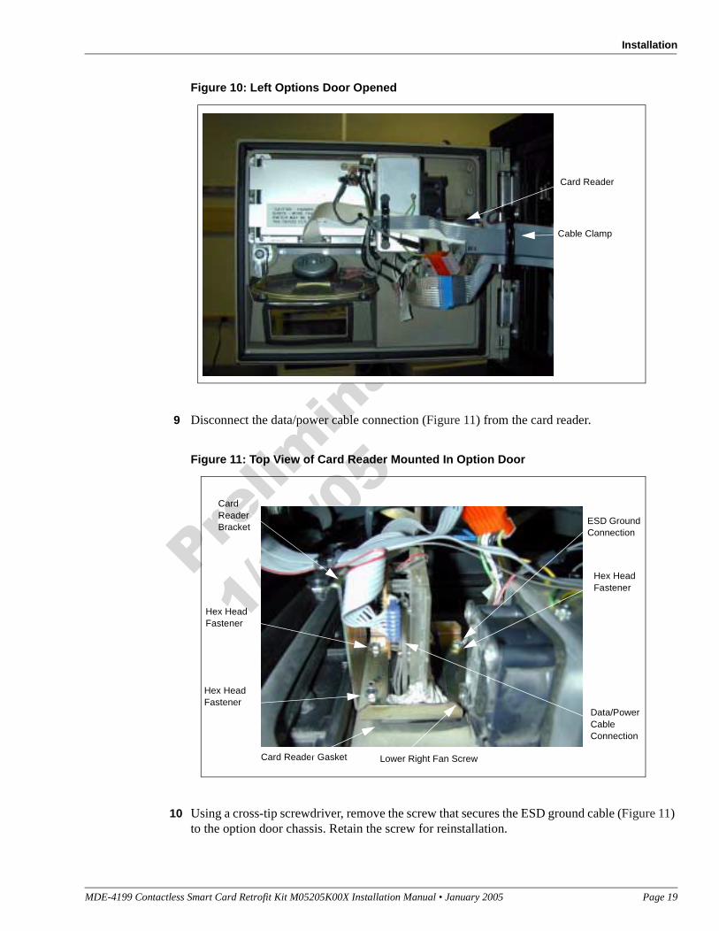
8 Remove the cable clamp (Figure 10) attached to the card reader mounting bracket.
9 Disconnect the data/power cable connection (Figure 11) from the card reader.
Figure 11: Top View of Card Reader Mounted In Option Door
10 Using a cross-tip screwdriver, remove the screw that secures the ESD ground cable (Figure 11) to the option door chassis. Retain the screw for reinstallation.
11 Using a 1/4-inch nut driver, remove the four hex head fasteners (Figure 11) that secure the card reader bracket (Figure 11) and the card reader to the options door. Dispose of the card reader.
Note: Make note of the card reader’s gasket orientation. This information will be useful when installing the new M00682B001 Card Reader Gasket. Also, ensure that the option door surface has been cleaned with isopropyl alcohol and a clean cloth prior to installing the new card reader gasket.
12 Remove the old card reader gasket (Figure 11) from the options door. Use a putty knife if necessary.
13 If installing a dual head card assembly on Side B, repeat steps 1 through 11.
Installing The Contactless Smartcard Reader
1 Remove the adhesive backing from the M00682B001 Card Reader Gasket and carefully place the gasket over the card reader opening from the inside of the opened option door.
Note: Fueling units that contain the InfoScreen option may require the removal of the lower right Infoscreen fan screw (Figure 11) to allow installation of the new RF Reader bracket. The screw may be discarded once the installation has been completed.
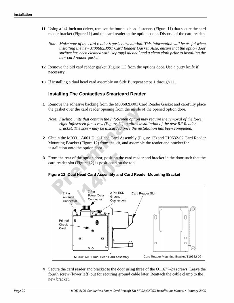
2 Obtain the M03311A001 Dual Head Card Assembly (Figure 12) and T19632-02 Card Reader Mounting Bracket (Figure 12) from the kit, and assemble the reader and bracket for installation onto the option door.
3 From the rear of the option door, position the card reader and bracket in the door such that the card reader slot (Figure 12) is positioned on the top.
Figure 12: Dual Head Card Assembly and Card Reader Mounting Bracket
4 Secure the card reader and bracket to the door using three of the Q11677-24 screws. Leave the fourth screw (lower left) out for securing ground cable later. Reattach the cable clamp to the new bracket.
Card Reader Slot
M03311A001 Dual Head Card Assembly Card Reader Mounting Bracket T19362-02
5 Reconnect the power/data cable to the seven-pin connector (Figure 12) on the Printed Circuit Card (PCA) located on the left side of the dual head card assembly.
6 Insert the connector end of the ESD Ground Cable M02134A001 (Figure 4) to the two-pin connector on the card reader PCA (Figure 12).
7 Attach the ring end of ESD Ground Cable M02134A001 (Figure 13) to the option door chassis using the screw removed in Step 10 of “Removing the Card Reader from the Advantage Series Unit”.
Refer to Figure 12 and ensure that the M02134A001 ESD Ground Cable is inserted into the correct connector on the dual head card assembly. Failure to connect the cable properly will damage the card reader.
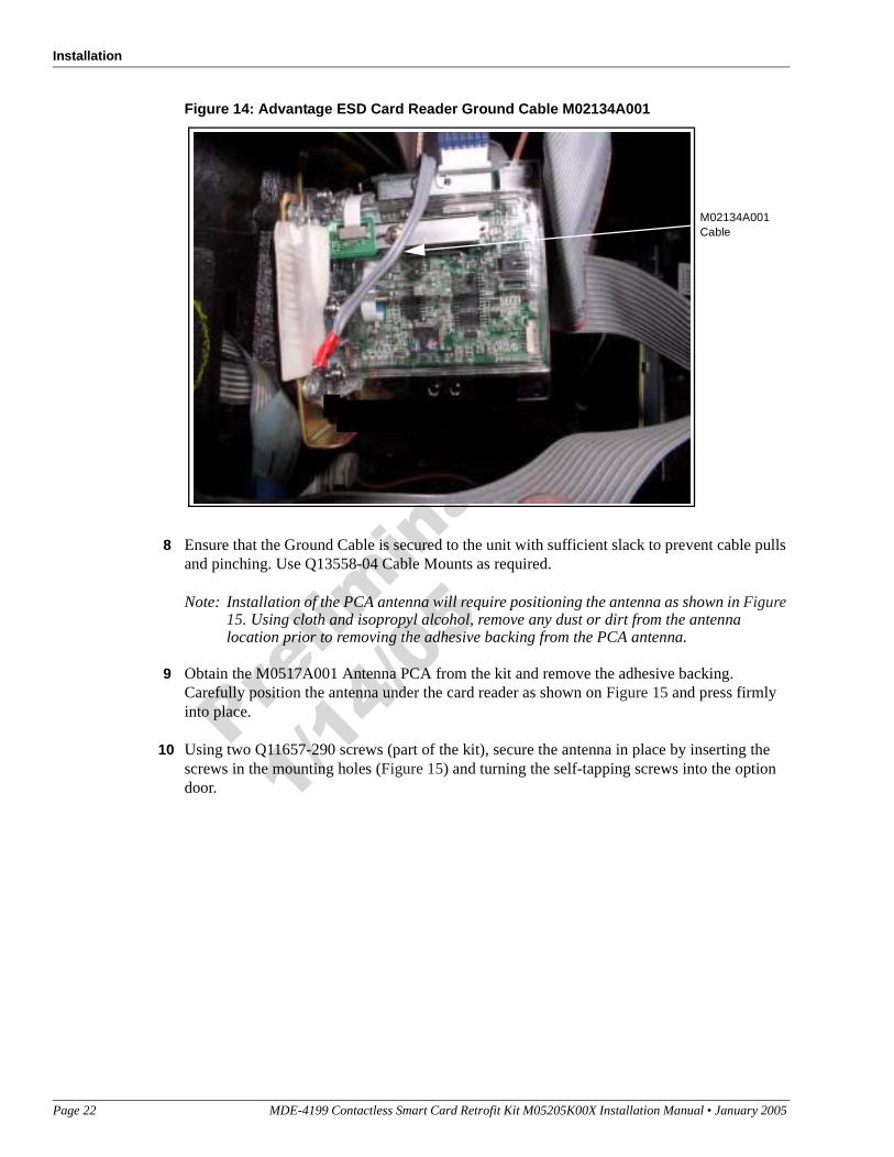
8 Ensure that the Ground Cable is secured to the unit with sufficient slack to prevent cable pulls and pinching. Use Q13558-04 Cable Mounts as required.
Note: Installation of the PCA antenna will require positioning the antenna as shown in Figure 15. Using cloth and isopropyl alcohol, remove any dust or dirt from the antenna location prior to removing the adhesive backing from the PCA antenna.
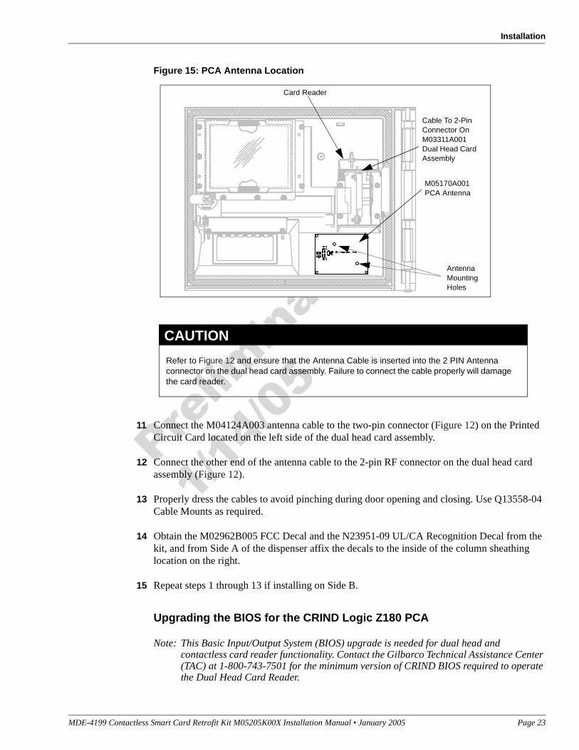
9 Obtain the M0517A001 Antenna PCA from the kit and remove the adhesive backing. Carefully position the antenna under the card reader as shown on Figure 15 and press firmly into place.
10 Using two Q11657-290 screws (part of the kit), secure the antenna in place by inserting the screws in the mounting holes (Figure 15) and turning the self-tapping screws into the option door.
11 Connect the M04124A003 antenna cable to the two-pin connector (Figure 12) on the Printed Circuit Card located on the left side of the dual head card assembly.
12 Connect the other end of the antenna cable to the 2-pin RF connector on the dual head card assembly (Figure 12).
13 Properly dress the cables to avoid pinching during door opening and closing. Use Q13558-04 Cable Mounts as required.
14 Obtain the M02962B005 FCC Decal and the N23951-09 UL/CA Recognition Decal from the kit, and from Side A of the dispenser affix the decals to the inside of the column sheathing location on the right.
15 Repeat steps 1 through 13 if installing on Side B.
Upgrading the BIOS for the CRIND Logic Z180 PCA
Note: This Basic Input/Output System (BIOS) upgrade is needed for dual head and contactless card reader functionality. Contact the Gilbarco Technical Assistance Center (TAC) at 1-800-743-7501 for the minimum version of CRIND BIOS required to operate the Dual Head Card Reader.
M05170A001PCA Antenna
Cable To 2-Pin Connector On M03311A001 Dual Head Card Assembly
Card Reader
Antenna Mounting Holes
Refer to Figure 12 and ensure that the Antenna Cable is inserted into the 2 PIN Antenna connector on the dual head card assembly. Failure to connect the cable properly will damage the card reader.
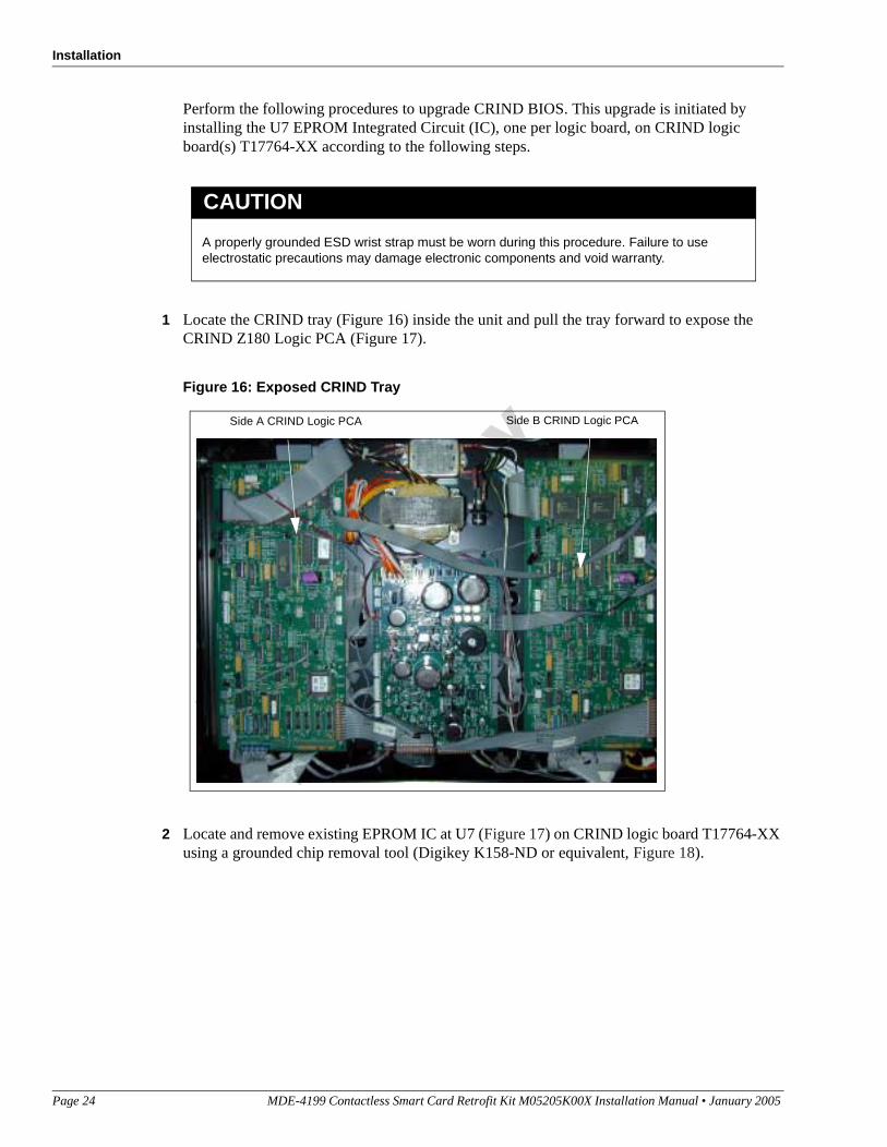
Perform the following procedures to upgrade CRIND BIOS. This upgrade is initiated by installing the U7 EPROM Integrated Circuit (IC), one per logic board, on CRIND logic board(s) T17764-XX according to the following steps.
1 Locate the CRIND tray (Figure 16) inside the unit and pull the tray forward to expose the CRIND Z180 Logic PCA (Figure 17).
Figure 16: Exposed CRIND Tray
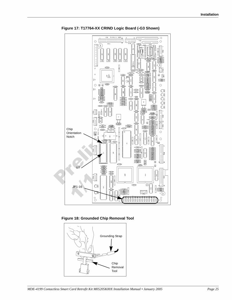
2 Locate and remove existing EPROM IC at U7 (Figure 17) on CRIND logic board T17764-XX using a grounded chip removal tool (Digikey K158-ND or equivalent, Figure 18).
A properly grounded ESD wrist strap must be worn during this procedure. Failure to use electrostatic precautions may damage electronic components and void warranty.
3 Install EPROM IC (one per logic board) at position U7, orienting notch on chip with indication mark on board as shown on Figure 17.
4 Install a jump jack on JP-11 (Figure 17) for each side of unit, as needed in order to Cold Start the unit.Note: Jumper on JP-11 informs the CRIND that a system Cold Start is present.
5 Restore power to the unit. Refer to MDE-2540 The Advantage, Legacy, and MPD Series Owners Manual for details on restoring system power.
6 Observe that CRIND BIOS software installs and runs properly. Refer to MDE-2562 CRIND Service Manual for details on CRIND BIOS installs and prompts.
7 Upon receiving a prompt from the CRIND BIOS to remove the Cold Start jumper, remove power from the unit. Refer to MDE-2540 The Advantage, Legacy, and MPD Series Owners Manual for details on removing system power.
8 Once power has been removed, remove the Cold Start jumper from JP-11 on the CRIND Logic board.
9 Restore the CRIND Tray to its original position.
Completing The Advantage Series InstallationPerform the following steps to complete installation.
1 Close and secure option and main doors.
2 Restore power to unit. Refer to MDE-2540 The Advantage, Legacy, and MPD Series Owners Manual.
3 Test the dual head card assembly by tapping the test card against the logo. The CRIND beeper will emit an audible beep upon performing a successful read.
4 Apply appropriate graphics and logos. These are order entry items. See MDE-2620 for graphic application instructions.
Installing M05205K004 Kit in The Advantage Series Unit With Cash AcceptorThe M05205K004 Kit contains parts for both side 1 and side 2 of The Advantage Series Unit. If both sides of the unit are being updated, all procedures performed on Side A of the unit must also be performed on Side B.
Removing the Card Reader from the Advantage Series UnitWhen installing a PayPass RF Reader Retrofit kit, the existing card reader must be removed and replaced with a dual head card assembly (part of the kit). Remove the existing card reader as follows:
1 Read all instructions before beginning procedure.
3 Obtain approval from store manager or responsible personnel to remove unit from service.
4 Remove power to the units. Refer to MDE-2540 The Advantage, Legacy, and MPD Series Owners Manual for details on removing system power.
5 Locate left and right options doors. Using the key, open the left and right option doors.
6 From side A, unlatch the four draw latches located behind the right and left options doors. Use a 5/32-inch Allen wrench or 3/8-inch Hex to loosen the four screws at bottom of main access door.
7 From side A, open the main access door by lifting slightly. Place the main access door hinge bracket pin into the end slot/lock position. This locks into a maximum 90° angle.
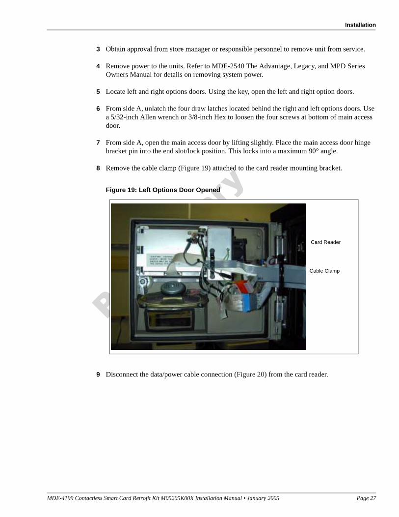
8 Remove the cable clamp (Figure 19) attached to the card reader mounting bracket.
Figure 19: Left Options Door Opened
9 Disconnect the data/power cable connection (Figure 20) from the card reader.
Figure 20: Top View of Card Reader Mounted In Option Door
10 Using a cross-tip screwdriver, remove the screw that secures the ESD ground cable (Figure 20) to the option door chassis. Retain the screw for reinstallation.
11 Using a 1/4-inch nut driver, remove the four hex head fasteners (Figure 20) that secure the card reader bracket (Figure 20) and the card reader to the options door. Dispose of the card reader and retain the fasteners for reinstallation.
Note: Make note of the card reader’s gasket orientation. This information will be useful when installing the new M00682B001 Card Reader Gasket. Also, ensure that the option door surface has been cleaned with isopropyl alcohol and a clean cloth prior to installing the new card reader gasket.
12 Remove the old card reader gasket (Figure 20) from the options door. Use a putty knife if necessary.
13 If installing a dual head card assembly on Side B, repeat steps 1 through 11.
Installing The Contactless Smartcard Reader Assembly
1 Remove the adhesive backing from the M00682B001 Card Reader Gasket and carefully place the gasket over the card reader opening from the inside of the opened option door.
Note: Fueling units that contain the InfoScreen option may require the removal of the lower right Infoscreen fan screw (Figure 20) to allow installation of the new RF Reader bracket. The screw may be discarded once the installation has been completed.
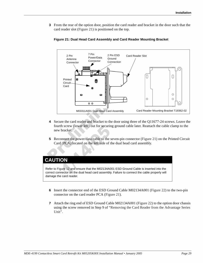
2 Obtain the M03311A001 Dual Head Card Assembly (Figure 21) and T19632-02 Card Reader Mounting Bracket (Figure 21) from the kit, and assemble the reader and bracket for installation onto the option door.
3 From the rear of the option door, position the card reader and bracket in the door such that the card reader slot (Figure 21) is positioned on the top.
Figure 21: Dual Head Card Assembly and Card Reader Mounting Bracket
4 Secure the card reader and bracket to the door using three of the Q11677-24 screws. Leave the fourth screw (lower left) out for securing ground cable later. Reattach the cable clamp to the new bracket.
5 Reconnect the power/data cable to the seven-pin connector (Figure 21) on the Printed Circuit Card (PCA) located on the left side of the dual head card assembly.
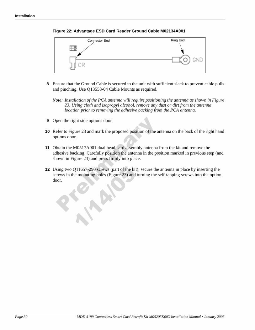
6 Insert the connector end of the ESD Ground Cable M02134A001 (Figure 22) to the two-pin connector on the card reader PCA (Figure 21).
7 Attach the ring end of ESD Ground Cable M02134A001 (Figure 22) to the option door chassis using the screw removed in Step 9 of “Removing the Card Reader from the Advantage Series Unit”.
Card Reader Slot
M03311A001 Dual Head Card Assembly Card Reader Mounting Bracket T19362-02
Printed Circuit Card
2 Pin Antenna Connector
7 Pin Power/Data Connector
2 Pin ESD Ground Connection
Refer to Figure 12 and ensure that the M02134A001 ESD Ground Cable is inserted into the correct connector on the dual head card assembly. Failure to connect the cable properly will damage the card reader.
8 Ensure that the Ground Cable is secured to the unit with sufficient slack to prevent cable pulls and pinching. Use Q13558-04 Cable Mounts as required.
Note: Installation of the PCA antenna will require positioning the antenna as shown in Figure 23. Using cloth and isopropyl alcohol, remove any dust or dirt from the antenna location prior to removing the adhesive backing from the PCA antenna.
9 Open the right side options door.
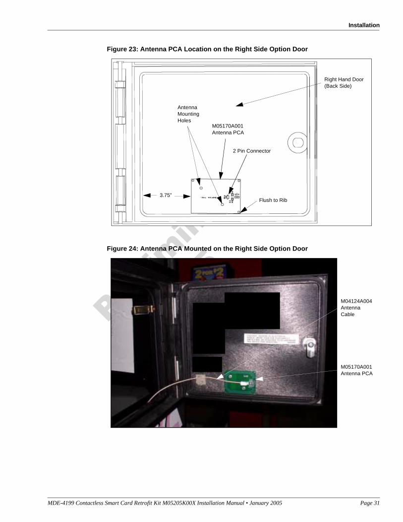
10 Refer to Figure 23 and mark the proposed position of the antenna on the back of the right hand options door.
11 Obtain the M0517A001 dual head card assembly antenna from the kit and remove the adhesive backing. Carefully position the antenna in the position marked in previous step (and shown in Figure 23) and press firmly into place.
12 Using two Q11657-290 screws (part of the kit), secure the antenna in place by inserting the screws in the mounting holes (Figure 23) and turning the self-tapping screws into the option door.
13 Connect the M04124A004 antenna cable to the two-pin connector (Figure 21) on the Printed Circuit Assembly located on the dual head card assembly.
14 Connect the other end of antenna cable to the 2-pin RF connector on the antenna (Figure 23).
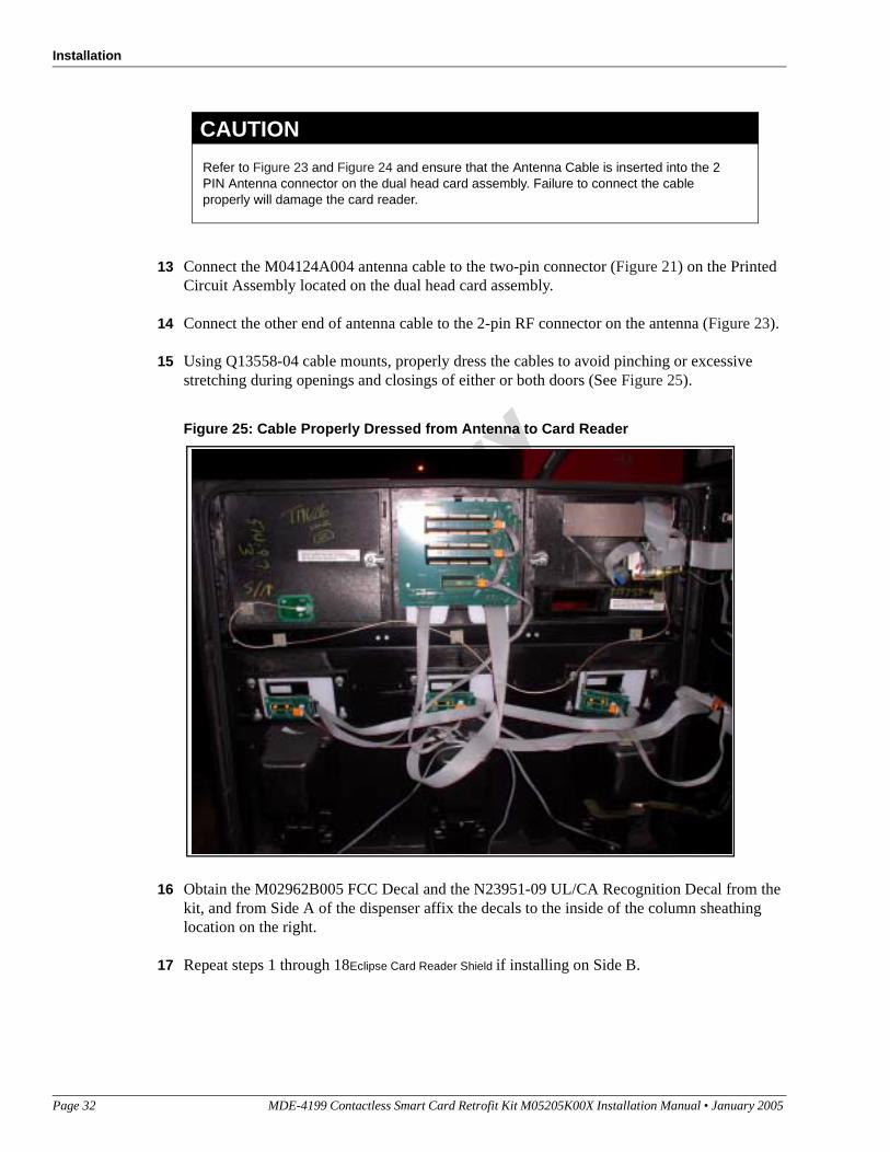
15 Using Q13558-04 cable mounts, properly dress the cables to avoid pinching or excessive stretching during openings and closings of either or both doors (See Figure 25).
Figure 25: Cable Properly Dressed from Antenna to Card Reader
16 Obtain the M02962B005 FCC Decal and the N23951-09 UL/CA Recognition Decal from the kit, and from Side A of the dispenser affix the decals to the inside of the column sheathing location on the right.
17 Repeat steps 1 through 18Eclipse Card Reader Shield if installing on Side B.
Refer to Figure 23 and Figure 24 and ensure that the Antenna Cable is inserted into the 2 PIN Antenna connector on the dual head card assembly. Failure to connect the cable properly will damage the card reader.
Note: This Basic Input/Output System (BIOS) upgrade is needed for dual head card assembly functionality. Contact the Gilbarco Technical Assistance Center (TAC) at 1-800-743-7501 for the minimum version of CRIND BIOS required to operate the Dual Head Card Reader.
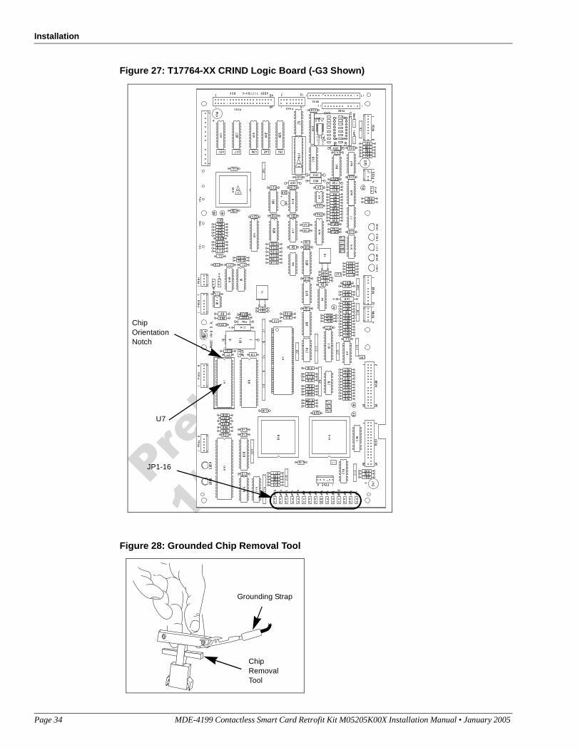
Perform the following procedures to upgrade CRIND BIOS. This upgrade is initiated by installing the U7 EPROM Integrated Circuit (IC), one per logic board, on CRIND logic board(s) T17764-XX according to the following steps.
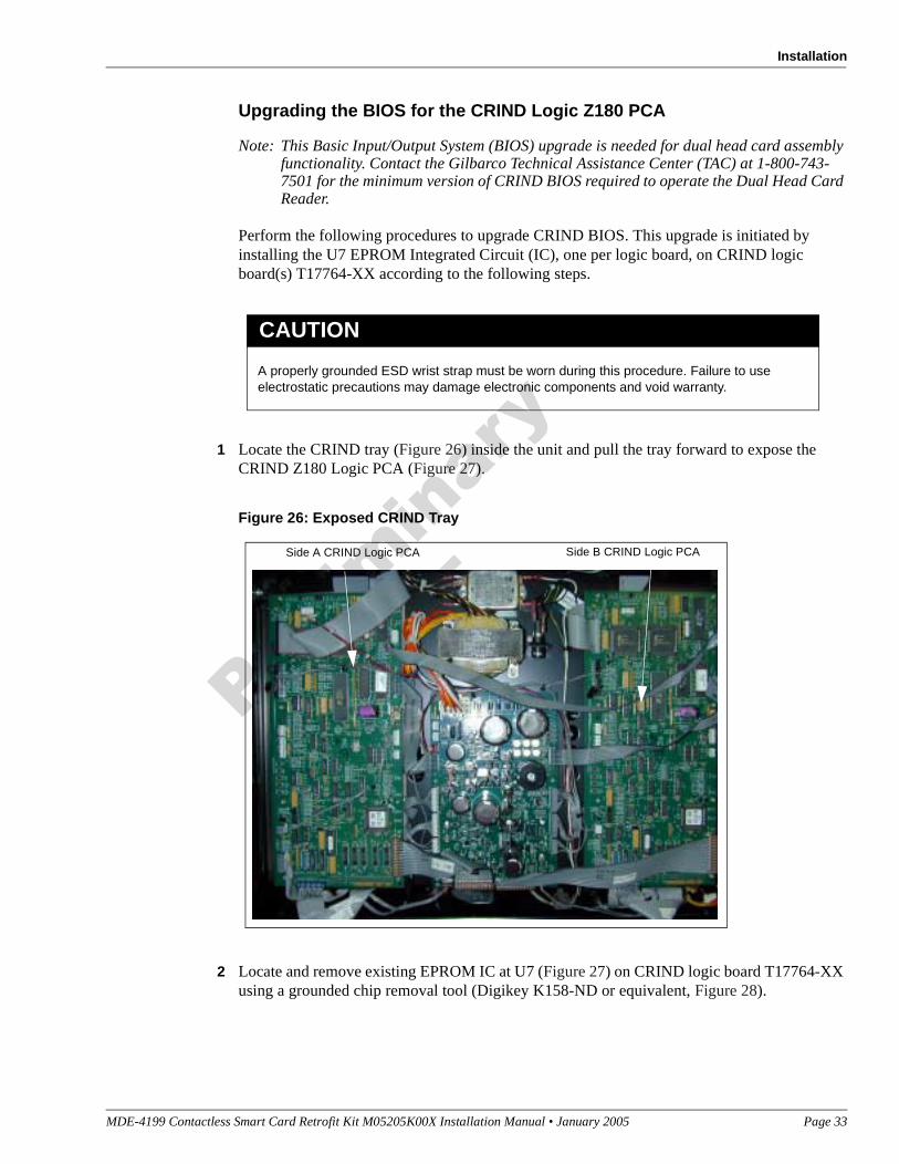
1 Locate the CRIND tray (Figure 26) inside the unit and pull the tray forward to expose the CRIND Z180 Logic PCA (Figure 27).
Figure 26: Exposed CRIND Tray
2 Locate and remove existing EPROM IC at U7 (Figure 27) on CRIND logic board T17764-XX using a grounded chip removal tool (Digikey K158-ND or equivalent, Figure 28).
A properly grounded ESD wrist strap must be worn during this procedure. Failure to use electrostatic precautions may damage electronic components and void warranty.
3 Install EPROM IC (one per logic board) at position U7, orienting notch on chip with indication mark on board as shown on Figure 27.
4 Install a jump jack on JP-11 (Figure 27) for each side of unit, as needed in order to Cold Start the unit.Note: Jumper on JP-11 informs the CRIND that a system Cold Start is present.
5 Restore power to the unit. Refer to MDE-2540 The Advantage, Legacy, and MPD Series Owners Manual for details on restoring system power.
6 Observe that CRIND BIOS software installs and runs properly. Refer to MDE-2562 CRIND Service Manual for details on CRIND BIOS installs and prompts.
7 Upon receiving a prompt from the CRIND BIOS to remove the Cold Start jumper, remove power from the unit. Refer to MDE-2540 The Advantage, Legacy, and MPD Series Owners Manual for details on removing system power.
8 Once power has been removed, remove the Cold Start jumper from JP-11 on the CRIND Logic board.
9 Restore the CRIND Tray to its original position.
Completing The Advantage Series InstallationPerform the following steps to complete installation.
1 Close and secure option and main doors.
2 Restore power to unit. Refer to MDE-2540 The Advantage, Legacy, and MPD Series Owners Manual.
3 Test the dual head card assembly by tapping the test card against the logo. The CRIND beeper will emit an audible beep upon performing a successful read.
4 Apply appropriate graphic logos. These are order entry items. See MDE-2620 for graphic application instructions.
CRIND®, Eclipse®, Encore®, GOLD®, Infoscreen®, The Advantage® Series, and TRIND® are registered trademarks of Gilbarco Inc.MasterCard® is a registered trademark of MasterCard International, IncorporatedPayPass™ is a trademark of MasterCard International, Incorporated