Introduction The Bioline Dosing Management Controller (BDMC) is designed to operate: • A simplex effluent pump (Duplex pump models available) • An automatic backflushing filter • A field flush valve • An indexing valve with up to eight zones • Up to 8 electric solenoid zone valves Glossary of Terms Dose – The volume of effluent sent to any one zone during a single pump cycle. Dose Event – The sequence of actions the controller manages which leads to the dispersal of effluent to a specific zone for an interval of time. Dose Time – The length of time in minutes that the controller directs water to a zone during a dose event. Dose Interval – The time between the start of two dose events as set by the doses per day. Field Flush – The event where water is rapidly pushed through the drip lines and all manifolds to remove accumulated debris. The flush water is returned to the pump tank or the treatment process. Field Flush Cycle – The event where a field flush occurs once for every zone. Field Flush Valve – Normally closed, this valve actuates a field flush when opened. Filter Backflush – Water flow through the filter is reversed to dislodge accumulated debris. The water used to backflush is returned to the treatment system. Normal filtration resumes after a filter backflush event. Float Tree – An assembly of float switches in the pump tank. The floats actuate the controller based on the effluent level in the pump tank. Indexing Valve – A simple mechanical valve that enables multiple zone operation without any electric solenoids. Pump, Simplex – A single pump used to operate all dosing and flushing operations. Pump, Duplex – Two pumps used alternately or in parallel to perform dosing and flushing operations. Zone – Refers to the combined distribution manifold, return manifold, drip lines and area of land receiving effluent from a single valve outlet. Zone Valve – Used to control the flow of effluent to a zone.
Transcript
Introduction The Bioline Dosing Management Controller (BDMC) is designed to operate:
• A simplex effluent pump(Duplex pump models available)
• An automatic backflushing filter • A field flush valve • An indexing valve with up to eight
zones• Up to 8 electric solenoid zone valves
Glossary of Terms
Dose – The volume of effluent sent to any one zone during a single pump cycle.
Dose Event – The sequence of actions the controller manages which leads to the dispersal of effluent to a specific zone for an interval of time.
Dose Time – The length of time in minutes that the controller directs water to a zone during a dose event.
Dose Interval – The time between the start of two dose events as set by the doses per day.
Field Flush – The event where water is rapidly pushed through the drip lines and all manifolds to remove accumulated debris. The flush water is returned to the pump tank or the treatment process.
Field Flush Cycle – The event where a field flush occurs once for every zone.
Field Flush Valve – Normally closed, this valve actuates a field flush when opened.
Filter Backflush – Water flow through the filter is reversed to dislodge accumulated debris. The water used to backflush is returned to the treatment system. Normal filtration resumes after a filter backflush event.
Float Tree – An assembly of float switches in the pump tank. The floats actuate the controller based on the effluent level in the pump tank.
Indexing Valve – A simple mechanical valve that enables multiple zone operation without any electric solenoids.
Pump, Simplex – A single pump used to operate all dosing and flushing operations.
Pump, Duplex – Two pumps used alternately or in parallel to perform dosing and flushing operations.
Zone – Refers to the combined distribution manifold, return manifold, drip lines and area of land receiving effluent from a single valve outlet.
Zone Valve – Used to control the flow of effluent to a zone.
For installations requiring a headworks heater, a Ground Fault Circuit Interrupter is installed in the external power connection box.
Pumps
The BDMC standard pump outputs are for single-phase, 120VAC, ½ HP, submersible turbine pumps.
Higher voltage/larger pump outputs are available by special order.
Hardware
• Sturdy plastic watertight outdoor boxes• Stainless Steel Clasp on main box• External power connection box available• Wall mounting hardware included• Most hardware is corrosion resistant
plastic, aluminum or stainless steel• Audible and visual alarms with a silence
button
BDMC Control Capabilities
Pumps: Simplex or Duplex configurationsZones: Up to 3 standard
Up to 8 by special orderAutomatic field flush valve controlCompatible with indexing valves
Filter: Requires an electric solenoidcontrolled flushing filterMultiple filter flushing by special order
Settings:Manage the number of zones,dose time and doses per day with the beep code programming and numbered dial
Alarms: High water alarmFloat error alarmHigh duty float alarm
General OperationThe Dose Schedule
The BDMC uses a schedule to evenly spread doses across a day. The user sets the number of doses per day which translates into the dose interval. For example, at 24 doses per day, the BDMC would try to dose once per hour.
When the time arrives for a dose, the BDMC checks the low float before proceeding. If the float is up, the dose begins. If the float is down, the BDMC skips this dose and waits until the next scheduled dose event. For multi-zone systems, skipping a dose event does not change which zone is next. The BDMC waits to increment the next scheduled zone until after a dose successfully starts.
Field Flush Cycle
A field flush cycle occurs anytime the controller is restarted and approximately once a week. The field flush cycle ends when all zones are flushed once. Systems that are set up with multiple zones will flush each zone in sequential scheduled doses.
The field flushes are important for keeping the drip emitters clean of biologic growth and sediment debris.
Duplex vs. Simplex Pump System
Simplex (single) pump setup: Only one pump runs for all filter flush, field flush and normal dose operations.
Duplex (double) pump setup:Two pumps run during filter and field flushes. The pumps alternate every dose for the regular dose time period. With the high duty float up, both pumps will run during the regular dose time as well.
The BDMC comes standard as a simplex mode controller. The duplex controller requires extra hardware and will need to be ordered specifically as duplex.
Start-Up OperationDose with Filter and Field Flush
After any power reset, the controller immediately restarts the dosing schedule and goes through a new field flush cycle.
The BDMC checks the status of the low float and begins a dose if the float is up. See “Normal Operation: Dose with Field Flush” for the sequence of events that follows.
If the BDMC is set to dose multiple zones, each zone is field flushed once at the normal scheduled interval.
Disabling the Field Flush
Depressing the “Silence Alarm” button during start-up disables the initial field flush cycle feature. To disable: depress the Silence Alarm Button while turning on the power to the controller using the BDMC breaker switch. Release the button after the beep.
*If you hold the button too long, the controller will enter into programming mode.
If sufficient water is available in the pump tank, the controller will perform a standard timed dose upon release of the switch.
Normal OperationNormal Dose Event
With the high duty float down and low float up, the BDMC will initiate a normal dose event.
1. Turn on pump (both for duplex)2. Filter flush for 30 seconds3. If duplex, turn off one pump4. Open the next scheduled zone valve5. Disperse effluent for the set dose
time6. Close the zone valve7. Turn off the pump
Dose Event with Field Flush
With the high duty float down and low float up, the BDMC will initiate a normal dose event.
1. Turn on pump (both for duplex)2. Filter flush for 30 seconds3. Open the next scheduled zone valve
and field flush valve4. Field flush for 6 minutes5. Close the field flush valve6. If duplex, turn off one pump7. If the dose time is greater than 6
minutes, continue to dose for the remainder of the dose time. A 10 minute dose time results in 4 minutes of remaining time.
8. Close the zone valve9. Turn off the pump
High Duty OperationMid Float/High Duty Float Up
If the mid float is up, any dose events will add 4 minutes to the dose time. If the system is setup for duplex operation, both pumps will come on just in case one pump failed.
When the mid float goes down, the controller will use normal dose times again.
1. Turn on pump (both for duplex)2. Filter flush for 30 seconds3. Open the next scheduled zone valve4. Disperse effluent for the set dose
time5. Continue dosing for 4 extra minutes6. Close the zone valve7. Turn off the pump(s).
The High Duty Float Alarm
If the high duty float ever rises, the alarm LED on the front panel will begin flashing to alert maintenance personnel that the system has had a high water level at some point. The LED flashes at a slow rate of ON for 2 seconds then OFF for 2 seconds.
Clear: Press the Silence Alarm Button.Auto Clear: If the mid float goes down, the alarm will clear itself
High Water Alarm ModeHigh Float/Alarm Float Up
The BDMC does not automatically start the high water alarm when the high float goes up. It will first try a couple extra times to lower the water level in an effort to prevent backflow into an owner's home.
If the alarm float is up while the controller is idle between doses, it immediately begins the following alarm dose sequence:
1. Turn on pump (both for duplex)2. Filter flush for 30 seconds3. Open the next scheduled zone valve4. Disperse effluent for 8 minutes5. Close the zone valve6. Turn off the pump(s).7. Check the alarm float – sound alarm
if float is still up
If the controller is successful at lowering the water level but the alarm float rises again later, it will repeat the above sequence. If the alarm float rises a third time in between scheduled doses, the alarm immediately sounds and the controller will not run through the alarm dose event.
The High Water Alarm
The alarm consists of evenly spaced beeps at approximately 1.5 beeps per second with a solid red alarm LED.
Silence: Press the Silence Alarm Button. Note that the alarm will resume beeping after 24 hrs of being silenced without a new “Silence Alarm” button push or system reset.Clear: Hold the “Silence Alarm” button for 8 seconds until the controller emits a double chirp then release the button.Auto Clear: If the alarm float goes down, the alarm will clear itself
FloatsThe BDMC uses three normally open Sensor Floats to manage the effluent in the pump tank. These floats must match the following specifications: a non-mechanical mercury switch with hysteresis of less than one inch. Floats similar to the SJE-Rhombus Sensor Float series are recommended.
The Float Malfunction Alarm
If the floats activate out of order (mid float before the low float for example), the controller enters an alarm state indicated by two rapid beeps/flashes followed by a short pause. The BDMC will continue to function as long as the low float still works.
The alarm can be silenced and will clear when the floats appear to be on in the correct order.
Float Operation ChartFloat Function
High (Alarm) Float
Indicates very high water level in pump tank and initiates action to relieve this condition
Mid (High Duty) Float
Indicates above average water level in storage tank. Adds 4 minutes to scheduled dosing time.
Low Float Assures the pump will not run dry. When it is in the up position, the controller will do the scheduled doses.
InstallationWarning! Working with high voltage electricity can be deadly. Use caution and safe electrical work practices when installing or hire an experienced electrician. Always turn off the power “downstream” of the part you are working on.
Preparing the Enclosures
Preparations for mounting
Use the included hanging kit to attach the four mounting feet to the back of the main box.
Place the BDMC against the wall in the planned location and mark the holes needed for pilot holes or anchors.
These screws will not require washers to securely hold the mounting feet in place.
Conduit Preparations
At this point, plan the wiring conduit runs. Most likely, ¾”-1” conduit will handle all the wire carrying needs but check local electrical code to size the wiring then figure out the minimum conduit size.
Once the necessary conduit fittings are determined, drill the proper holes in the BDMC enclosures. Make sure the holes are sized correctly to provide a tight fit with the fittings.
When installing the fittings, make sure to seal the gap around the fitting to keep water, insects, and gases out of the BDMC.Silicone sealant or rubber gaskets are fine.
Hole Saw Sizing1/2” Conduit: 7/8”3/4” Conduit: 1-1/16” (best fit) or 1-1/8”1” Conduit: 1-5/16” (best fit) or 1-3/8”
Hole Location Suggestions
Power Connections
For wire size reference, the continuous load values for the components are:
120VACPump (½ HP): 10 A (per pump)BDMC Controls: 1 AHeater: 1 A
24VACZone Solenoid: 0.13 AFilter Flush: 0.25 A
5VDCFloats: 5 mA
Check with local code to determine the wire gauge necessary to run power wire to the BDMC and wire to the pumps.
For short wire runs (<30 ft), these wire gauges are a good place to start:
Once the wire and conduit is determined, finish hanging the BDMC and prepare to install the circuit breaker and conduit from the home's electrical service distribution box.
The next steps should be performed by a professional electrician to ensure proper safety and correct wiring .
Before working in the electrical service distribution box, use the power disconnect to remove power and verify with a voltmeter. Install the new circuit breaker for the BDMC (see previous section Specifications: Electrical). Finish the
conduit between the BDMC and electrical service distribution box. Pull the Line, Neutral, and Ground wires to the BDMC.
Note: For a BDMC without an external power terminal box, the middle plate must be removed from the controller to access the power and pump terminals. Otherwise, finish the power connections in the external box.
Power Terminal ConnectionsPower 120VAC:
Line (hot) wire from circuit breakerPower Neutral:
Neutral wire from neutral busGrounding Lug/Terminal:
Ground wire from separate ground bus
Once wiring is complete, close up the electrical service distribution box and switch power back on. Test the new connection to the BDMC with a voltmeter.
Before continuing installation, TURN OFF the BDMC power circuit breaker in the electrical service distribution box and verify that no power is reaching the BDMC.
External Terminal Box
No External Terminal Box
Installation Procedure: Pump Power
Install the conduit from the BDMC to the pump tank riser and pull the Power, Neutral, and Ground wires (per pump). A junction box in the conduit run may be necessary for the pump connection splices.
Pump Terminal ConnectionsPump Power:
Line (hot) wire to pumpPump Neutral:
Neutral wire to pumpGrounding Lug/Terminal:
Ground wire to pump
IMPORTANT: Seal the the conduit and wire exit into the pump tank riser. Gases and moisture can destroy BDMC parts if they travel through the conduit into the box.
External Terminal Box
No External Terminal Box
Installation Procedure: Floats
While installing the float wire conduit, add a junction box either inside the pump tank riser or just outside the riser. This will allow you to run just four wires out to the floats and provides an air gap between the float wires and the BDMC. Past experiences have shown that gases can travel through the float wire insulation.
Float Wires1. Low Float Signal2. Mid (High Duty) Float Signal3. High (Alarm) Float Signal4. Float Common
In the junction box, connect the white wires of all the floats to the Float Common and then each black wire to its respective signal wire.
IMPORTANT: Seal the the conduit between the BDMC and junction box. Gases and moisture can destroy BDMC parts if they travel through the conduit.
In the BDMC, each float has a pair of wire terminals. The terminal marked with a diamond represents the common 5VDC output sent to the floats. The unmarked terminal is the float's signal input.
Connect the Float Common to one of the terminals marked by the small diamond. Each signal wire goes to the appropriate signal input terminal.
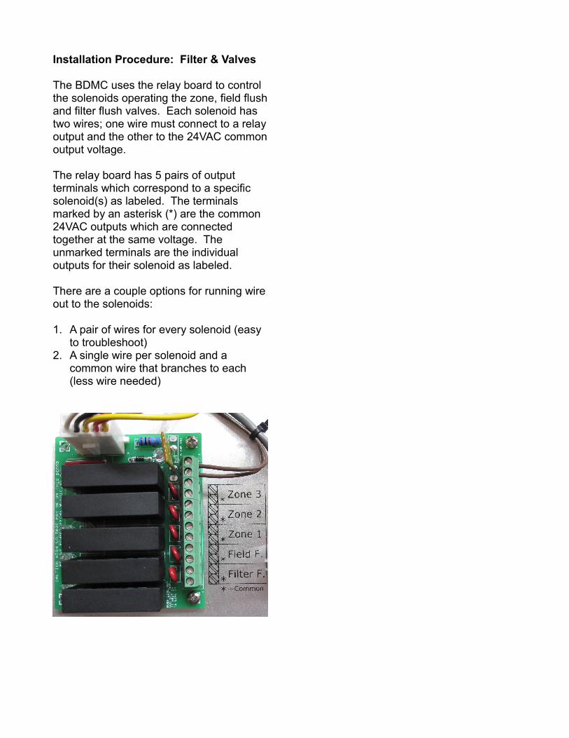
Installation Procedure: Filter & Valves
The BDMC uses the relay board to control the solenoids operating the zone, field flush and filter flush valves. Each solenoid has two wires; one wire must connect to a relay output and the other to the 24VAC common output voltage.
The relay board has 5 pairs of output terminals which correspond to a specific solenoid(s) as labeled. The terminals marked by an asterisk (*) are the common 24VAC outputs which are connected together at the same voltage. The unmarked terminals are the individual outputs for their solenoid as labeled.
There are a couple options for running wire out to the solenoids:
1. A pair of wires for every solenoid (easy to troubleshoot)
2. A single wire per solenoid and a common wire that branches to each (less wire needed)
BDMC SettingsAccess the Setup Mode
The BDMC settings and diagnostics modes are entered through a beep code menu system.
To access these modes:
1. Turn OFF the BDMC power2. Hold down the Silence Alarm Button
and do not release until specified later3. Turn ON the BDMC power4. The controller will beep and flash all 4
LEDs then holds the “Power On” and “System Alarm” LEDs active
5. After 8 seconds, the BDMC enters the programming mode and emit a series of beeps like:
1. beep, pause2. beep-beep, pause3. beep-beep-beep, pause4. etc.
6. The number of consecutive beeps represents the setup mode, i.e. beep-beep means mode 2
7. Release the Silence Alarm Button after the set of beeps representing the desired setup mode
8. After the set of 5 beeps, the controller will not restart the beep series; cycle the power and enter programming mode again if trying to get to an earlier setup mode
Number of Beeps
Setup Mode
1 Float Check Mode2 Firmware Version Mode3 Dose Time Setup4 Number of Zones Setup5 Manual Diagnostics Mode
Float Status Mode
This diagnostics mode allows the user to test each float and demonstrate the High Water Alarm.
The BDMC checks the floats and emits certain beeps if a float is up. The following list is the order and output for the floats:
Low: beep, pauseMid: beep-beep, pauseHigh: High Water Alarm (stops the routine
and the system MUST be reset)
As long as the high float is down, the float status mode will keep looping after going through the beep outputs for the low and mid floats (if any). Test the high float only after the low and mid float.
Exit this mode by pressing the Silence Alarm Button until the BDMC does two chirps.
Firmware Version Mode
Going into this mode outputs the firmware version of the controller microprocessor.
The firmware version consists of three numbers and will be output in a format of: beeps (1st number), pause, beeps (2nd
number), pause, beeps (3rd number). After a long pause, the BDMC will loop through the firmware beeps again.
Count the consecutive beeps of the three series to find the firmware numbers.
For example:beep, pause, beep-beep, pause, beep-beep-beep-beep → version 1.2.4
Exit this mode by pressing the Silence Alarm Button until the BDMC does two chirps.
Dose Time Setup
Initially, the default dose time is set to six (6) minutes which is appropriate for many systems operating in heavy soils. Please check with the system designer to figure out the correct dose time for a given soil type and required daily dispersal.
As soon as the BDMC enters this mode, it will begin emitting a number of beeps indicating the current dose time in minutes (e.g. six consecutive beeps for 6 minutes).
The rotary dial has 16 positions numbered 1-16 which will be used to set the pump run time. In this mode, each position represents the dose time in minutes so only 6-16 are valid settings. For example, a dial setting of 10 would be for 10-minute doses
To change the dose time:1. Turn the rotary dial to the new position 2. If the dial was already on the new
setting, turn it to position 1 until the controller stops beeping then put it back to the correct position
3. The controller will now confirm the setting chosen by beeping out that number
4. Make sure it beeps out the correct number; it might take another series of beeps to get the right output
5. Press the Silence Alarm Button until the controller chirps twice then release
6. The new setting is now saved and the controller will restart
Number of Zones Setup
The default number of zones is one (1). No programming is necessary for single zone systems. All systems allow settings for 1-8 zones; however, if the BDMC does not have enough zone outputs, the pumps will still run and just dead head.
When entering the zone setup mode, the BDMC will begin beeping out the current number-of-zones setting as a series of consecutive beeps. For example, three zones would be three beeps in a row followed by a pause.
This mode uses the rotary dial like the dose time setup mode. Positions 1-8 are valid and correspond directly to the number of zones.
To change the number of zones:1. Turn the rotary dial to the new position 2. If the dial was already on the new
setting, turn it to a different position until the BDMC starts beeping the temporary position's number; now turn the dial to the desired number
3. The controller will now confirm the setting chosen by beeping out that number
4. Make sure it beeps out the correct number; it might take another series of beeps to get the right output
5. Press the Silence Alarm Button until the controller chirps twice then release
6. The new setting is now saved and the controller will restart
Manual Diagnostics Mode
In this diagnostics mode, the user can turn on a specific zone and pump using the dial.
This can be used to check that the pumps are working or that the solenoids on the field valves are working properly.
Just turn the dial to the position corresponding to the desired pump/zone combination. The BDMC will activate them automatically and will keep the outputs on until the dial is changed or the controller is reset.
To exit this mode and turn off the pumps and valves, press the Silence Alarm Button until the BDMC chirps twice. Release and the controller will reset.
Manual Field Flush
If the drip system is only equipped with a manual field flush valve, then open the valve and dose/flush the zones in the manual diagnostics mode.
Programming Shortcut
After exiting a programming mode, the controller chirps twice and and will reset the controller when the Silence Alarm Button is released. Immediately following the button release, press and hold the button again and proceed as if power had just been turned on.
This method skips cycling the power just to get to another programming mode.
This setting is not reached through the beep codes. Instead, just set the dial to the position desired then reset the power. The controller looks at the dial position when it powers up to figure out which dose interval it should use. Any dial position changes while the BDMC is on will not be read.
This setting should be specified by the drip system designer but the calculations are usually as follows:
Assuming every zone has similar flows:
System Daily Flow gal /day One Zone Dispersal gpm
=Daily RunTime
min /day
Daily RunTime min /dayDose Length min /dose
=Doses per Day
Typically, the result should be rounded up to the next available dosing schedule. An extra couple of doses per day is less of a problem than too few and can help with the occasional water overload days.
Note: A system with many doses per day and short dose lengths reacts to the high water use periods better than less but longer doses. The pump tank never gets a chance to fill up if it is constantly getting pumped down little by little. The downside is possible extra component wear. The system designer should take these ideas into consideration when specifying the settings.