56
Introduction to 3G Mobile Communications Systems Communications Systems Dr. Hicham Aroudaki Damascus, 15 h May 2010
Introduction to 3G Mobile Communications SystemsCommunications Systems
Dr. Hicham Aroudaki
Damascus, 15h May 2010

2nd Generation Mobile Communications Systems
GSMGlobal System for Mobile Communicationsince 1992900, 1800 & 1900 MHz
PDCPersonal Digital Cellularsince 1993/94Japan only800 & 1500 MHz
IS-95Interim Standard-95since 1995America & S. Korea800 & 1900 MHz, 1700 MHz (Korea)
D-AMPSDigital AMPSsince 1991/92USA, Kanada800 & 1900 MHzAMPS/D-AMPS
� Digital systems
� Roaming
� Voice & data
� Comfortable use

What End Users are Looking for
adsvideo
2
news
gamesbanking
sport results
payment
email/MMS
stocks

Bandwidth Demand of Different Service Types
Se
rvic
e
Database accessInformation services
Video telephony
Teleshopping
TelebankingFinancial services
Electronic newspaperImages / sound files
3
10 kbps 100 kbps 1 Mbps
Information services
Voice
Development in Mobile Communications
The technical development is driven by 3 main aspects
4
� More bandwidth/data rate on the Air Interface
� ALL IP
� Network intelligence to a “service” layer

Development Directions
• Faster Data
rates
• Decreased • Access independence for
services
FASTER
Wid
er S
co
pe
5
Radio Network Core Network
• Decreased
Latency
• High Cell Edge
Throughput
• Spectrum
Flexibility
services
• Standardized multimedia
services
• Mobility and IP
interworking for all
accesses
Wid
er S
co
pe
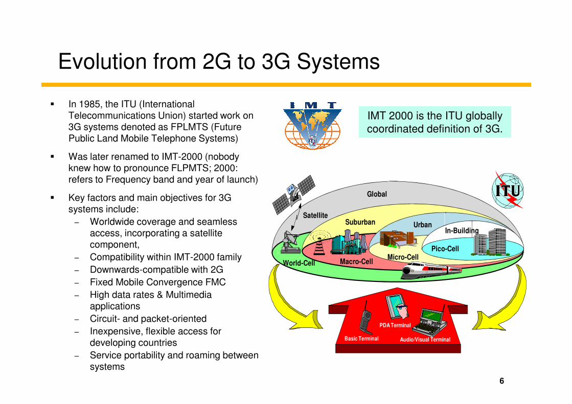
Evolution from 2G to 3G Systems
� In 1985, the ITU (International Telecommunications Union) started work on 3G systems denoted as FPLMTS (Future Public Land Mobile Telephone Systems)
� Was later renamed to IMT-2000 (nobody knew how to pronounce FLPMTS; 2000: refers to Frequency band and year of launch)
� Key factors and main objectives for 3G Global
IMT 2000 is the ITU globally
coordinated definition of 3G.
� Key factors and main objectives for 3G systems include:
– Worldwide coverage and seamless access, incorporating a satellite component,
– Compatibility within IMT-2000 family
– Downwards-compatible with 2G
– Fixed Mobile Convergence FMC
– High data rates & Multimedia applications
– Circuit- and packet-oriented
– Inexpensive, flexible access for developing countries
– Service portability and roaming between systems
6
Satellite
Macro-CellMicro-Cell
UrbanIn-Building
Pico-Cell
Suburban
Basic Terminal
PDA Terminal
Audio/Visual Terminal
World-Cell

Evolution from 2G to 3G Systems
� During the evaluation of different proposals by the ITU it turned out that the vision
of a global standard with a single radio interface was not realizable for 3G
systems.
� This was due to the various 2G technologies used in different regions in the
world. It would have been impossible to find one technology as an evolutionary
path for all existing 2G systems.
� Therefore, a five member family concept was adopted and agreed upon at the � Therefore, a five member family concept was adopted and agreed upon at the
end of 1999.
� These five standards are now being further developed in the regional
standardization bodies.
• IMT-2000 CDMA Direct Spread, also known as UTRA FDD including WCDMA in Japan, ARIB / DoCoMo recommendation. UMTS is developed by 3GPP.
• IMT-2000 CDMA Multi-carrier, also known as Cdma2000 (3X) developed by 3GPP2
• IMT-2000 CDMA2000 includes 1X components, like cdma2000 1X EV-DO.
• IMT-2000 CDMA TDD, also known as UTRA TDD and TD-SCDMA. TD-SCDMA is developed in China and supported by TD_SCDMA Forum
• IMT-2000 TDMA Single Carrier, also known as UWC-136 (Edge) supported by UWCC
• IMT-2000 DECT supported by DECT Forum
7

What is 3GPP?
� 3GPP is a collaborative agreement between Standards Development
Organizations (SDOs) and other related bodies for the production of a complete
set of globally applicable Technical Specifications & Reports for:
– a 3G System based on the evolved GSM core network and the Universal Terrestrial Radio Access
(UTRA), FDD and TDD modes.
– the Global System for Mobile communication (GSM) including GSM evolved radio access
technologies.
� 3GPP has no legal status, but:
– The 3GPP results are jointly owned by
the Organizational Partners (i.e. the SDOs).
– The Organizational Partners transpose the results into their own deliverables (e.g. Standards) .
� 3GPP is open to the members who belong to each Organizational Partner.
� Currently, more than 450 Individual Member companies are actively engaged in
the work of 3GPP.
8
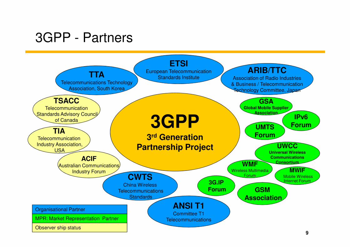
3GPP - Partners
3GPP
ETSIEuropean Telecommunication
Standards InstituteARIB/TTC
Association of Radio Industries
& Business / Telecommunication
Technology Committee, Japan
UMTS
GSAGlobal Mobile Supplier
Association
TSACCTelecommunication
Standards Advisory Council
of Canada
TTATelecommunications Technology
Association, South Korea
IPv6
Forum
9
3GPP3rd Generation
Partnership Project
CWTSChina Wireless
Telecommunications
Standards
UMTS
Forum
GSM
Association
MPR: Market Representation Partner
Organisational Partner
Observer ship status
TIATelecommunication
Industry Association,
USA
ANSI T1Committee T1
Telecommunications
UWCCUniversal Wireless
Communications
Consortium
Forum
WMFWireless Multimedia
ForumMWIF
Mobile WirelessInternet Forum3G.IP
Forum
ACIFAustralian Communications
Industry Forum

IMT 2000 Standards Family Members
UMTS
Standard CDMA2000UTRA-FDD UTRA-TDD UWCC136 DECTTD-SCDMA
unpairedFreq. band unpairedunpaired pairedpaired paired
Page 10
IMT-2000
Core network compatibility
Standardisation
bodies
IMT-MCIMT-DS IMT-TD IMT-SC IMT-FT
ANSI-41GSM MAP GSM MAP ANSI-41 ISDN
3GPP23GPP 3GPP
GSM MAP
CWTS
3GPP
ETSITIA (U.S.)
IMT-2000 CDMA MC (multi carrier)
IMT-2000 CDMA DS (direct spread)
IMT-2000 TDMA SC (single carrier)
IMT-2000 FDMA/TDMA
IMT-TD
One mode ofIMT-2000 CDMA TDD(�UTRA-TDD)
Freq. band
Other mode of IMT-2000 CDMA TDD(�TD-SCDMA)
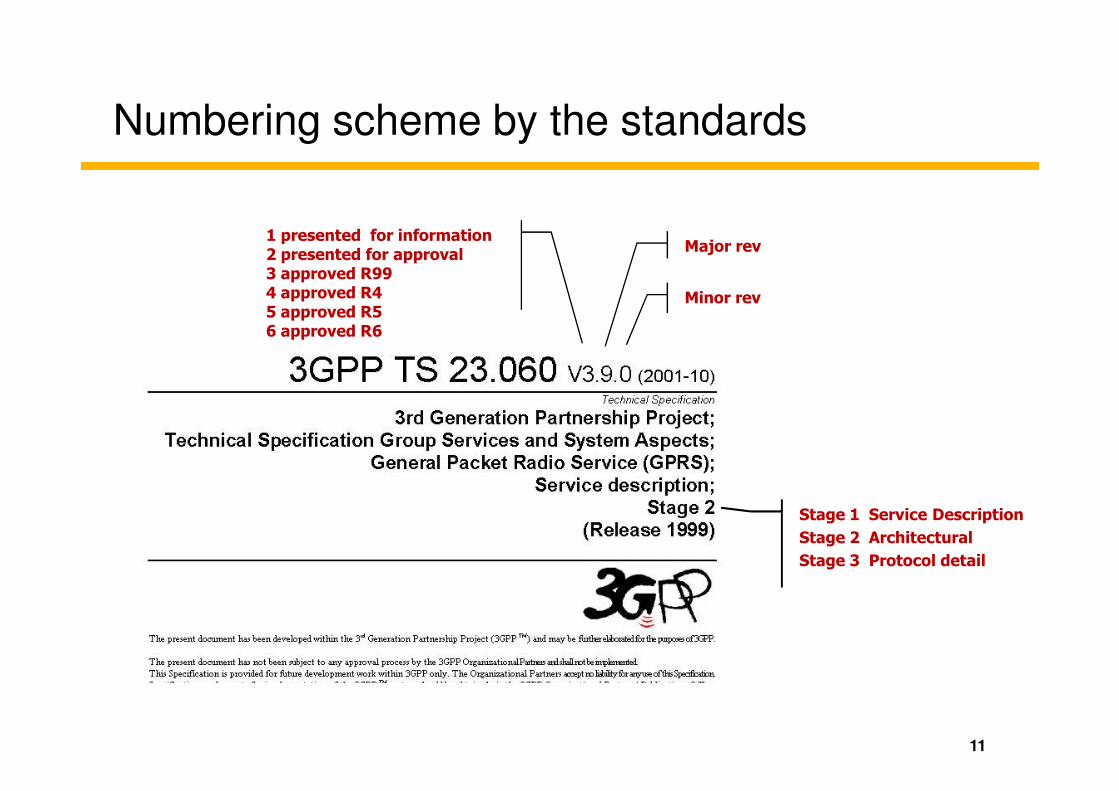
Numbering scheme by the standards
1 presented for information2 presented for approval3 approved R994 approved R45 approved R56 approved R6
Major rev
Minor rev
11
Stage 1 Service Description
Stage 2 Architectural
Stage 3 Protocol detail
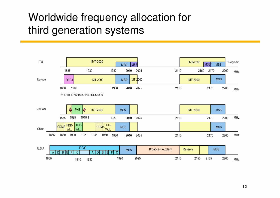
Worldwide frequency allocation for third generation systems
ITU
2010 20251980
MSS MSS*
1930
IMT-2000MSSMSS*
IMT-2000
2160 2170 2200 MHz
*Region2
1885 2110
1980 2110 22002170
IMT-2000 MSS
19001880
DECT
2010
MSSIMT-2000 IMT-2000
2025 MHz
Europe
** 1710-1755/1805-1850:DCS1800
12
PHS
20101980 2025
JAPAN
2110 22002170
IMT-2000 MSSMSSIMT-2000
18951885 1918.1 MHz
2110 220021652150
Reserve MSSBroadcast Auxilary
1990 2025
MSS
1850
PCS
A
PCS
1910 1930
B CD E F A B CD E F
MHz
U.S.A
20101980 2025
China
2110 22002170
MSSMSS
1900 1920 MHz1865 1880 1945 1960
CDMAFDD-
WLL
FDD-
WLLCDMA
TDD-
WLL
PCSPCS
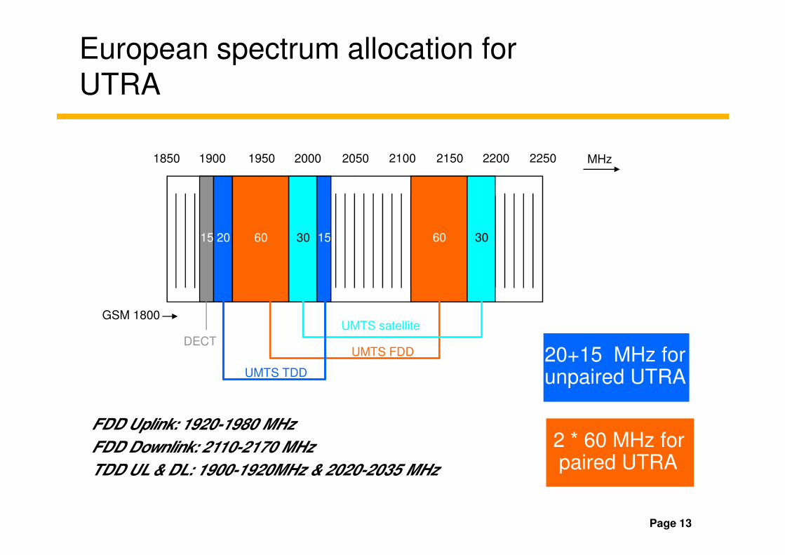
1850 1900 1950 2000 2050 2100 2150 2200 2250
15 20 60 30 15 60 30
MHz
European spectrum allocation for UTRA
Page 13
20+15 MHz for unpaired UTRA
2 * 60 MHz forpaired UTRA
UMTS satellite
DECT
GSM 1800
UMTS FDD
UMTS TDD
FDD Uplink: 1920-1980 MHz
FDD Downlink: 2110-2170 MHz
TDD UL & DL: 1900-1920MHz & 2020-2035 MHz
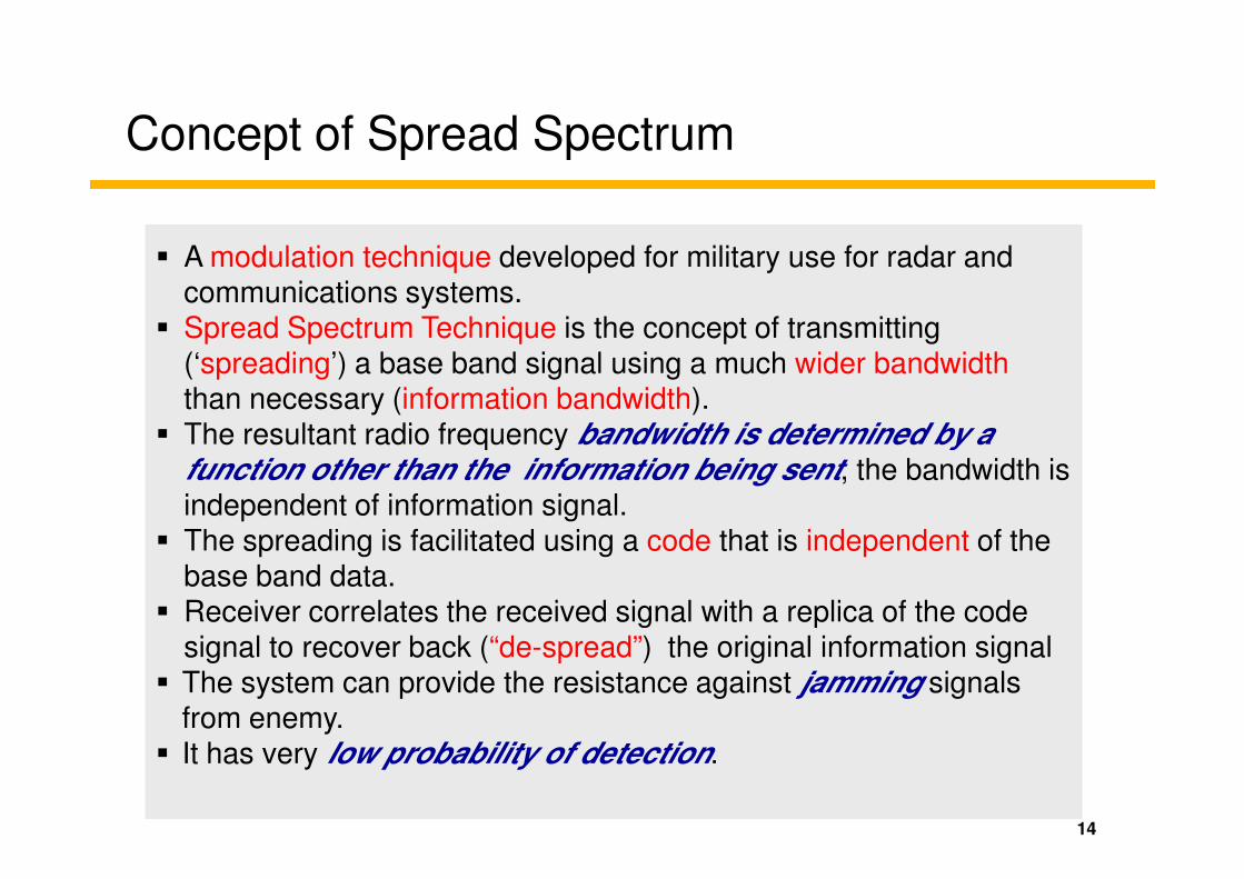
Concept of Spread Spectrum
� A modulation technique developed for military use for radar and communications systems.
� Spread Spectrum Technique is the concept of transmitting (‘spreading’) a base band signal using a much wider bandwidththan necessary (information bandwidth).
� The resultant radio frequency bandwidth is determined by a
14
� The resultant radio frequency bandwidth is determined by a function other than the information being sent, the bandwidth is independent of information signal.
� The spreading is facilitated using a code that is independent of the base band data.
� Receiver correlates the received signal with a replica of the code signal to recover back (“de-spread”) the original information signal
� The system can provide the resistance against jamming signals from enemy.
� It has very low probability of detection.
Historical Background
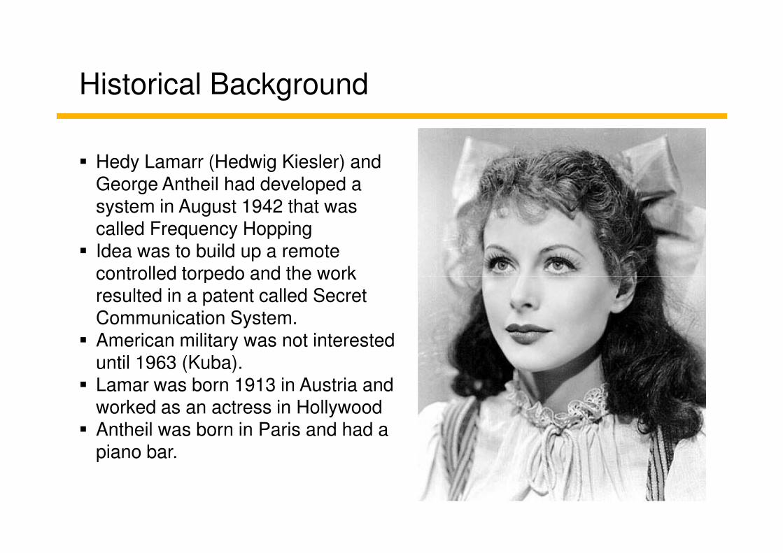
� Hedy Lamarr (Hedwig Kiesler) and George Antheil had developed a system in August 1942 that was called Frequency Hopping
� Idea was to build up a remote controlled torpedo and the work controlled torpedo and the work resulted in a patent called Secret Communication System.
� American military was not interested until 1963 (Kuba).
� Lamar was born 1913 in Austria and worked as an actress in Hollywood
� Antheil was born in Paris and had a piano bar.

Lamarr and Antheil's patent
Two pages of drawings from Lamarr and Antheil's patent. Note the player-piano-like slotted paper on the second sheet. Markey is the name of Hedy Lamarr's second of six husbands.
16

Spread Spectrum Modulation
Information Bits
Spreading Sequence
Spread SignalSpreading Sequence has a higher Rate-of Transition, causing the Spreading of the Spectrum.
17
[ -1 1 1 -1 1 -1 1 -1-1 1]
Information Bits
Spreading Sequence
Spreading Signal
“1” “0”
-1
+1

Spread Spectrum Transmitter/Receiver
Base band
signal
RF
Modulator
Code
Generator
X
Multiplier
Code Bits (Chips)
Digital Signal (Bits)BasebandSpectrum
f
“Spread” FrequencySpectrum
f
18
Generator Spectrum
RF
DemodulatorDespread
Signal
Code
Generator
X
Multiplier
Code Bits (Chips)
Transmitter
Receiver
BasebandSpectrum
f
“Spread” FrequencySpectrum
f
LP
Filter

Spread Spectrum PrinciplesInterference Suppression
MODf
P
f
PSignal
19
LPDEMOD
f
P
f
P
f
P
Narrowband interference
Wideband interference
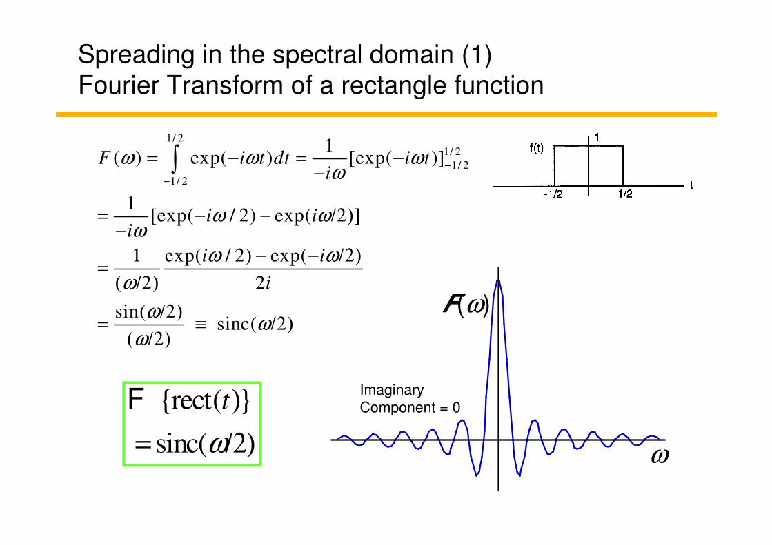
Spreading in the spectral domain (1)
Fourier Transform of a rectangle function
1/ 2
1/ 2
1/ 2
1/ 2
1( ) exp( ) [exp( )]
1[exp( / 2) exp(
exp( / 2) exp(
2
F i t dt i ti
i ii
i i
i
ω ω ωω
ω ωω
ω ω
ω
−
−
= − = −−
= − − /2)]−
1 − − /2)=
( /2)
∫
2
sin(sinc(
iω
ωω
ω
=( /2)
/2)= ≡ /2)
( /2)
{rect( }
sinc(
t
ω
)
= /2)
FImaginary
Component = 0
F(ω)
ω

Spreading in the spectral domain (2)
The Scale Theorem
f(t) F(ω)
Short
pulse
ωt
The shorter the pulse,
the broader the spectrum!
Medium-
length
pulse
Long
pulse
ω
ω
t
t
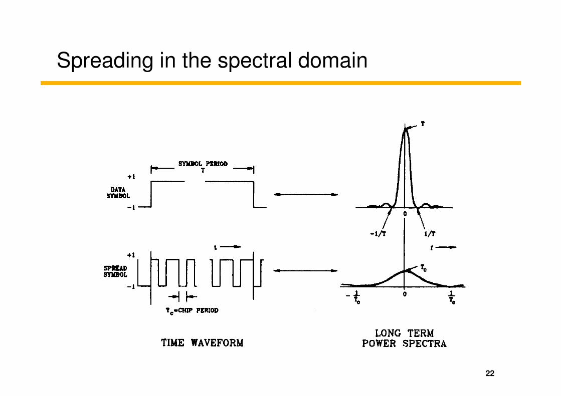
Spreading in the spectral domain
22
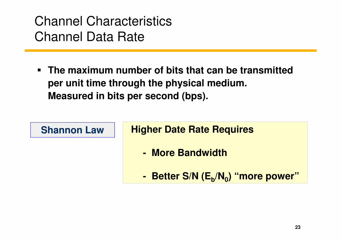
Channel CharacteristicsChannel Data Rate
� The maximum number of bits that can be transmitted
per unit time through the physical medium.
Measured in bits per second (bps).
23
Higher Date Rate Requires
- More Bandwidth
- Better S/N (Eb/N0) “more power”
Shannon Law

How Transmission Performance is Measured?
BER
Operating Point
24
Target: low error and low energy/bit
S/NLink Margin
Spread Spectrum Concept
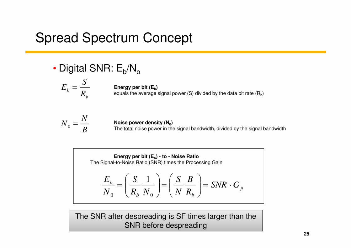
• Digital SNR: Eb/No
b
bR
SE = Energy per bit (Eb)
equals the average signal power (S) divided by the data bit rate (Rb)
NN =0
Noise power density (N0)
25
p
bb
b GSNRR
B
N
S
NR
S
N
E⋅=
=
=
00
1
Energy per bit (Eb) - to - Noise RatioThe Signal-to-Noise Ratio (SNR) times the Processing Gain
BN =0
Noise power density (N0)The total noise power in the signal bandwidth, divided by the signal bandwidth
The SNR after despreading is SF times larger than the
SNR before despreading

26
CDMA concept

CDMA - Transmission and Reception
De-
Spreading
CodeGenerator
De-
Modulation
Time
synchronization
RC
RB
User 1
Pow
er
Spreading
CodeGenerator
WidebandModulation
CarrierGenerator
RB
RC fT
bits chipssymbols
Pow
er
Air Interface
27
de-spreading
using Code No.3
Frequency
Pow
er
RB: Bit Rate
RC : Chip Rate
fT : Carrier frequency
User 1
f
Pow
er
f
Pow
er
f
Frequency
Frequency
Frequency
User 2
User 3
ΣΣΣΣ spread signals
Frequency
Pow
er
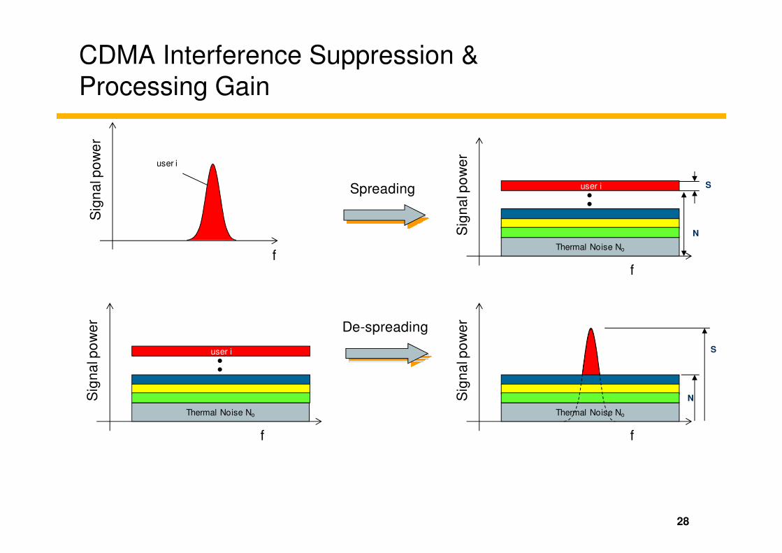
CDMA Interference Suppression &
Processing Gain
f
Sig
na
l po
we
r
user i
Spreading
f
Thermal Noise No
Sig
na
l po
we
r
user i�
�
S
N
28
f
f
Thermal Noise No
Sig
na
l po
we
r
user i�
�
De-spreading
f
Thermal Noise No
Sig
na
l po
we
r
S
N

Code Orthogonality
Orthogonal functions have zero correlation.
Geometry Information Theory
29
Two binary sequences are orthogonal if the
process of multiplying them results in equal +1s
& -1s
Example: -1 -1 1 1
-1 1 -1 1
1 -1 -1 1

Spreading Sequences – Desired Properties
• Autocorrelation
– suppression of self interference (non-zero time shifts of the
same code)
– ideally a delta pulse
E{c1(t)c1(t+τ)}
τ
30
– ideally a delta pulse
– in practice close to zero at τ≠0
• Cross-correlation
– suppression of inter-user interference
– ideally zero
– in practice close to zero
τ
τ
E{c1(t)c2(t+τ)}

Code Correlation
Input Data +1 -1 +1
Case I: Autocorrelation using a PN Code
Receiver and Transmitter use identical code at same time offset
+1 –1 +1 +1 –1 -1 +1 -1 +1 –1 +1 +1 –1 -1 +1 -1 +1 –1 +1 +1 –1 -1 +1 -1
PN code used
in Transmitter
x x x
+1 –1 +1 +1 –1 -1 +1 -1 -1 +1 -1 -1 +1 +1 -1 +1 +1 –1 +1 +1 –1 -1 +1 -1Transmitted
= = =Transmitter
+1 -1 +1Divide by
Code Length
+8 -8 +8
Integrate
Result
Integrate Integrate Integrate
+1 –1 +1 +1 –1 -1 +1 -1 -1 +1 -1 -1 +1 +1 -1 +1 +1 –1 +1 +1 –1 -1 +1 -1Transmitted
Sequence
+1 +1 +1 +1 +1 +1 +1 +1 -1 –1 –1 –1 –1 –1 –1 -1 +1 +1 +1 +1 +1 +1 +1 +1
= = =
+1 –1 +1 +1 –1 -1 +1 -1 +1 –1 +1 +1 –1 -1 +1 -1 +1 –1 +1 +1 –1 -1 +1 -1PN Code
Used in Receiver
x x x
Receiver

Code Correlation
Input Data +1 -1 +1
+1 –1 +1 +1 –1 -1 +1 -1 +1 –1 +1 +1 –1 -1 +1 -1 +1 –1 +1 +1 –1 -1 +1 -1
+1 –1 +1 +1 –1 -1 +1 -1 -1 +1 -1 -1 +1 +1 -1 +1 +1 –1 +1 +1 –1 -1 +1 -1
PN code used
in Transmitter
Transmitted
Case II: Cross-Correlation using PN Codes
Receiver and Transmitter use different codes
x x x
= = =Transmitter
+1 –1 +1 +1 –1 -1 +1 -1 -1 +1 -1 -1 +1 +1 -1 +1 +1 –1 +1 +1 –1 -1 +1 -1
-1 +1 –1 +1 +1 –1 -1 +1 +1 -1 +1 –1 +1 +1 –1 -1 -1 +1 +1 +1 –1 -1 +1 +1
-1 –1 –1 +1 –1 +1 –1 -1 -1 –1 –1 +1 +1 +1 +1 -1 -1 –1 +1 +1 +1 +1 +1 -1
Transmitted
Sequence
PN Code
Used in Receiver
-4 0 2
Integrate
Result
-0.50
0.25Divide by
Code Length
Integrate Integrate Integrate
x x x
= = =Receiver

CDMA – Basic concept
ft
f
t
f
User1: C1
User2: C2
User3: C3
time
Power
33
f
t
f
t
User3: C3
User4: C4
frequency
� The communications Channel is the Code.
� Physical resource occupancy is the transmit power.
A physical resource is a Coded channel transmitted at a given level of Power for a certain time length "Frame”.
� No time or frequency Orthogonality between users is required.

Spreading in
34
Spreading in
WCDMA
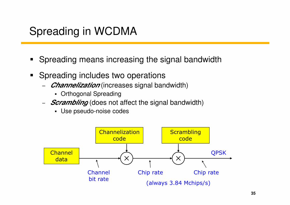
Spreading in WCDMA
� Spreading means increasing the signal bandwidth
� Spreading includes two operations– Channelization (increases signal bandwidth)
� Orthogonal Spreading
– Scrambling (does not affect the signal bandwidth)– Scrambling (does not affect the signal bandwidth)
� Use pseudo-noise codes
35
Channel data
Channelization code
Scrambling code
Channel bit rate
Chip rate Chip rate
(always 3.84 Mchips/s)
QPSK
Channelization in WCDMA
� Increases the bandwidth– Based on Orthogonal Variable Spreading Factor (OVSF)
– Codes are fully orthogonal, i.e., they do not interfere with each other
– Only if the codes are time synchronized
� It can separate the transmissions from a single source
� In DL: it can separate different users within one cell/sector
In UL: it separates the physical channels/services of one user � In UL: it separates the physical channels/services of one user
� Limited orthogonal codes must be reused in every cell– Problems:
� In DL: Interference, if two cells use the same code
� In UL: Mobiles are not synchronized in time
� Two mobiles can use the same code
– Solution is Scrambling :
� Scrambling codes are used to separate different users in the UL &
different cells in the DL.
36
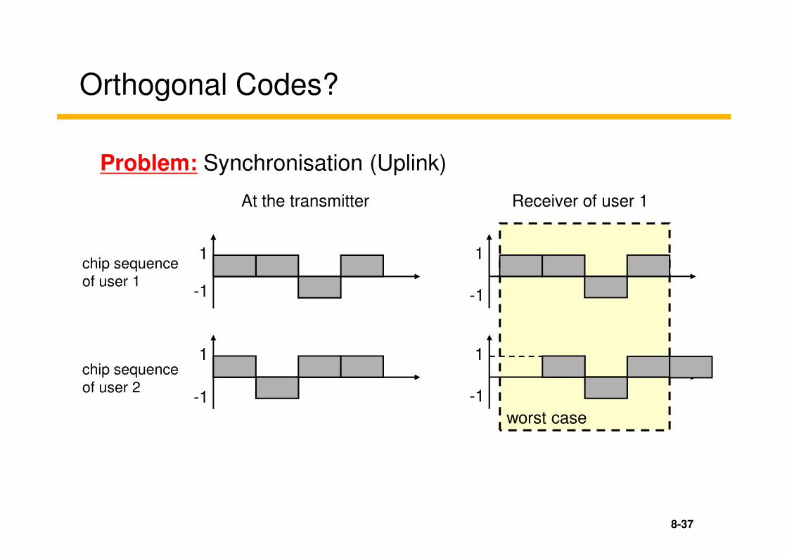
Orthogonal Codes?
Problem: Synchronisation (Uplink)
1 1chip sequence
of user 1
At the transmitter Receiver of user 1
8-37
-1
1
-1
-1
1
-1
worst case
of user 1
chip sequence
of user 2
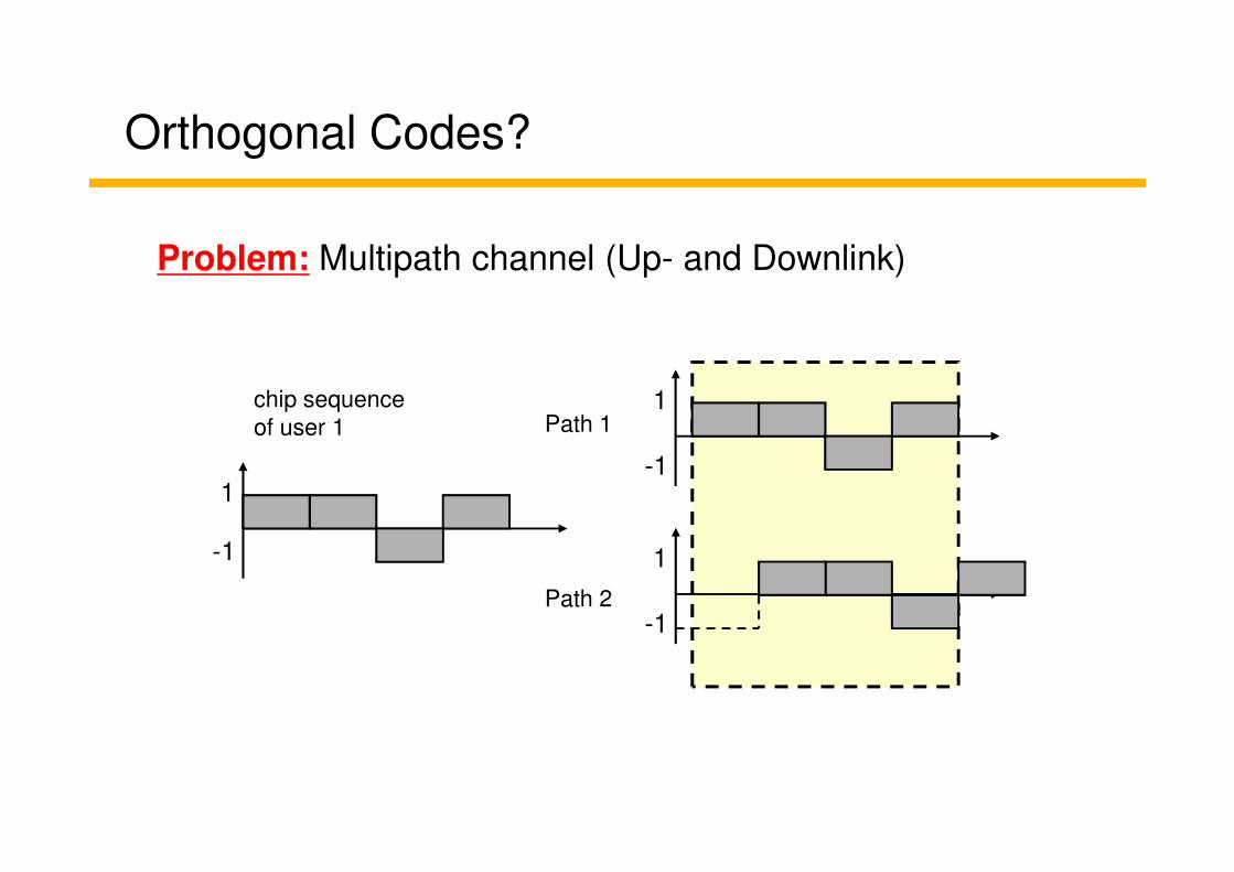
Orthogonal Codes?
Problem: Multipath channel (Up- and Downlink)
1chip sequence
of user 1 Path 1
1
-1
-1
1
-1
of user 1 Path 1
Path 2
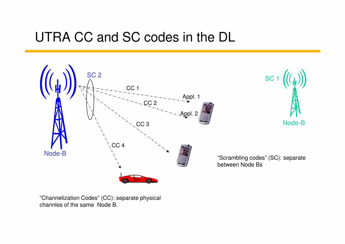
UTRA CC and SC codes in the DL
SC 2
CC 1
CC 2
CC 3
Appl. 1
Appl. 2
SC 1
Node-BCC 3
CC 4
Node-B
Node-B
“Channelization Codes” (CC): separate physical channles of the same Node B.
“Scrambling codes” (SC): separate between Node Bs

UTRA CC and SC code in the UL
SC 2CC 1
CC 2
“Scrambling Codes” (SC): Differentiate between UE (RNC allocated)
Node-B
CC 1
CC 2
CC 3
SC1“Channelization codes” (CC): separate UL different applicationsof 1 UE (max. 6; SF variable)

Orthogonal Codes
• When you send data using Orthogonal Codes...
User 1 Data: Multiply with Orthogonal Code User 1 Orthogonal-spread Data:
Transmitted “chips”Data
Orthogonal Code
D/A conv.
41
User 1 Data:
1 0 1
Multiply with Orthogonal Code
1 –1 1-1
User 1 Orthogonal-spread Data:
-1 1-1 1 1-1 1-1 -1 1-1 1
You send one orthogonal (channelization) code for every data bit!
If you want to send a digital “0”, you transmit the assigned channelization code
If you want to send a digital “1”, you transmit the inverted channelization code
D/A conv.
-1 +1 -1
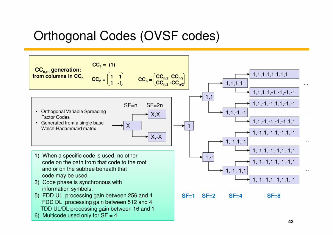
Orthogonal Codes (OVSF codes)
1,1
1,1,1,1
1,1,-1,-1
1,1,-1,-1,1,1,-1,-1
1,1,1,1,1,1,1,1
1,1,1,1,-1,-1,-1,-1
...
...
CC1 = (1)
CC2 = 1 1
1 -1CCn =
CCn/2 CCn/2
CCn/2 -CCn/2
CCn,m generation:from columns in CCn
X,X
SF=n SF=2n• Orthogonal Variable Spreading
Factor Codes
42
SF=1 SF=2 SF=4 SF=8
1
1,-1
1,-1,1,-1
1,-1,-1,1
1,-1,-1,1,1,-1,-1,1
1,-1,-1,1,-1,1,1,-1
1,-1,1,-1,1,-1,1,-1
1,-1,1,-1,-1,1,-1,1
1,1,-1,-1,-1,-1,1,1
...
...
X
X,-X
Factor Codes
• Generated from a single base
Walsh-Hadammard matrix
1) When a specific code is used, no other code on the path from that code to the root and or on the subtree beneath that code may be used.
3) Code phase is synchronous withinformation symbols.
5) FDD UL processing gain between 256 and 4FDD DL processing gain between 512 and 4
TDD UL/DL processing gain between 16 and 16) Multicode used only for SF = 4

Orthogonal Codes (OVSF codes)
• OVSF Code Space: 8 users; one 8-bit code per user
Chip Rate = 3.840 Mcps1
1-1 11
43
480 kb/s 480 kb/s 480 kb/s 480 kb/s 480 kb/s 480 kb/s 480 kb/s 480 kb/s
1-11-1 1-1-11 11-1-1 1111
1-11-11-11-11-11-1-11-11 1-1-111-1-111-1-11-111-1 11-1-111-1-111-1-1-1-111 1111-1-1-1-1 11111111
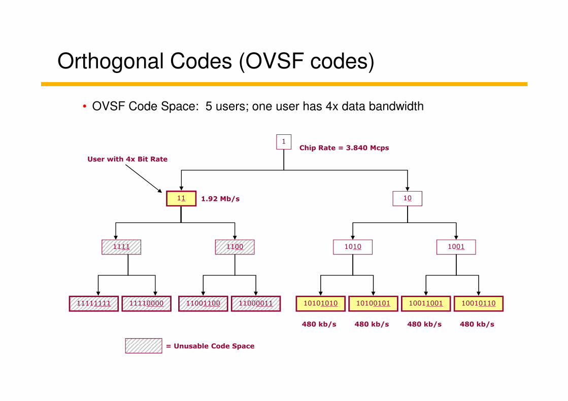
Orthogonal Codes (OVSF codes)
• OVSF Code Space: 5 users; one user has 4x data bandwidth
User with 4x Bit Rate
1.92 Mb/s
Chip Rate = 3.840 Mcps1
11 10
= Unusable Code Space
480 kb/s 480 kb/s 480 kb/s 480 kb/s
1.92 Mb/s11 10
1111 1100 1010 1001
11111111 11110000 11001100 11000011 10101010 10100101 10011001 10010110

WCDMA Shared Resources
Codes(Orthogonal)
kbps*
3840
1920
960
480
240
120
…
• Gross bitrate.Effective bitrate is less due to channel overhead
SF
1
2
4
8
16
32
…
45
Max PowerPower
15 256
Code 1
Code 2
Code 3

Channelization & Scrambling codes
46

GSM & UMTS Network Architecture
BTSBSC
MSC PSTN
PCU
circuit switched traffic
3G MSC
47
NodeB
NodeB SGSN Serving GPRS Supprt Node
GGSN Gateway GPRS Support Node
SGSN InternetGGSN
BTS BSC
RNC Radio Network Controller
PCUpacket oriented traffic
RNC
RNC
Iur
3G SGSN 3G GGSN

Defining UTRAN
GMSCMSC
Core Network
Node B Iub
Node B
USIM
Cu
Uu
AN (UTRAN)
AN (UTRAN)
Iu
Iu CS
UE
RNC
Iur
� The user
equipment (UE)
can be roughly
divided into USIM
(UMTS
Subscriber
Identity Module)
and ME (Mobile INHLR
GGSNSGSN
Node BRNC
Node BRNS
ME
Iu PS
and ME (Mobile
Equipment).
� The Uu-interface
is the radio
interface between
UE and the
Access Network
(UTRAN).
� The UMTS Terrestrial Radio Access Network (UTRAN) identifies that part of the network
which consists of RNCs and Node Bs (between the Uu- and Iu-interface).
� Within the UTRAN there are additional interfaces, e.g. Iub and Iur.
� The Iu-interface is the interconnection between UTRAN and the core network.

Network Structure
MSC
G MSC
A
VLR
Core Network (CN)
B
F D
PSTN
MSC/VLR
HLR/AC
BTS
Node B
BSC
Abis
BTS
BSSIu
49
S GSN
G GSN
Iu PS
HLREIR ACSCP/CSE
F D
C
H
Gf Gr Gc
Gi
Gp
Gn
UMSC
HLR/ACHLR-i
Node B
Node B
RNC
Iub
Node BRNS
Node B
USIM
UE
Cu
Uu
ME

Tasks of the single components (I)
MSC
� Mobile-services Switching Centre (MSC)� Routing of interlocutions
� Localisation procedures
� Handover procedures
� Home Location Register (HLR)
� Visitor Location Register (VLR)� Location information about locally registered MS
� Copies of data from the HLRVLR
� Home Location Register (HLR)� Subscriber information
� Current VLR, SGSN
� Service-specific information/authorisationHLR

Tasks of the single components (II)
SGSN
� Serving GPRS Support Node (SGSN)� Subscriber information
� Micro-mobility
� Routing of packets
� Gateway GPRS Support Node (GGSN)
� GPRS Register (GR)� Part of the HLR
� Storage of the permitted PDP contextsGR
� Gateway GPRS Support Node (GGSN)� Endpoint of the IP-tunnel
� Implementation onto GTP-u, PDP context
� Macro-mobilityGGSN

Tasks of the single components (III)
� Radio Network Controller (RNC)� Resource assignment, Handover decision
� Macro-Diversity (Soft Handover)
� MAC, RLC, RRC und Iu-Interface
RNC
Node B� Node B� BTS in GSM
� Inner Loop Power Control, Synchronisation
� Layer 1 tasks (PHY)
Node B
� User Equipment (UE)� UTRA-TDD, UTRA-FDD, GSM Single or
Multimode Terminal
� Contains the USIM
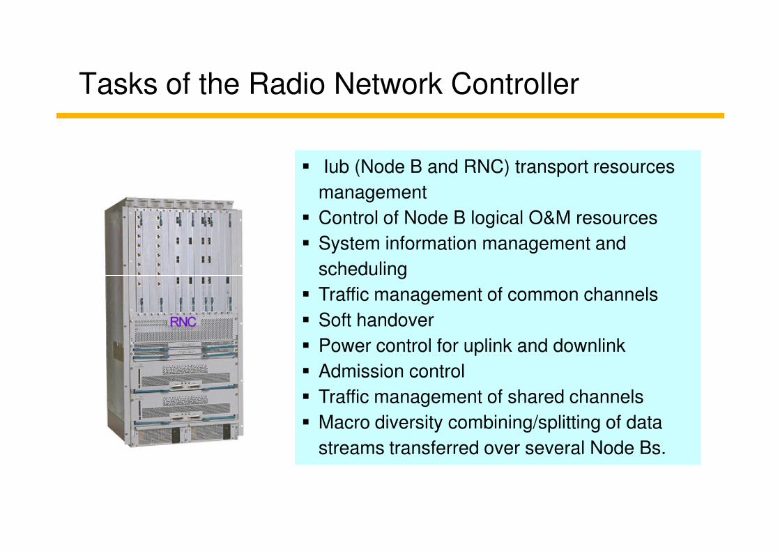
� Iub (Node B and RNC) transport resources
management
� Control of Node B logical O&M resources
� System information management and
scheduling
� Iub (Node B and RNC) transport resources
management
� Control of Node B logical O&M resources
� System information management and
scheduling
Tasks of the Radio Network Controller
scheduling
� Traffic management of common channels
� Soft handover
� Power control for uplink and downlink
� Admission control
� Traffic management of shared channels
� Macro diversity combining/splitting of data
streams transferred over several Node Bs.
scheduling
� Traffic management of common channels
� Soft handover
� Power control for uplink and downlink
� Admission control
� Traffic management of shared channels
� Macro diversity combining/splitting of data
streams transferred over several Node Bs.

Tasks of Node B
� Node B is the UMTS equivalent of a base station transceiver. It may support one or more cells, although in general only one cell one Node B.
� It is a logical terminal and the base station is often used for physical entity.
� Functions– Mapping of Node B logical resources onto
hardware resources
– Uplink power control
– Reporting of uplink interference measurements and downlink power information
– Contains the air interface physical layer, it has to perform many functions such as RF processing, modulations, coding, and so on.

UE as Node B counterpart, e.g.:
� FEC (encoding & Interleaving), rate adaption
� Spreading & Modulation, RF processing
� Power Control (Outer & Inner Loop)
� Meassurements (BER, FER, S/N, signal quality and signal strength),...
UE as Node B counterpart, e.g.:
� FEC (encoding & Interleaving), rate adaption
� Spreading & Modulation, RF processing
� Power Control (Outer & Inner Loop)
� Meassurements (BER, FER, S/N, signal quality and signal strength),...
Tasks of the UE
UE as RNC counterpart, e.g.:
� BEC (Acknowledged Transmission)
� Participates at RRC (Request, ...)
� Handover (CS) & cell selection (PS)
� Ciphering and deciphering, ...
UE as RNC counterpart, e.g.:
� BEC (Acknowledged Transmission)
� Participates at RRC (Request, ...)
� Handover (CS) & cell selection (PS)
� Ciphering and deciphering, ...
UE as CN counterpart, e.g.:
• Mobility Management
• (Location Registration, Authentication, IMEI Check, ...)
• Bearer Negotiation
• Service Request
UE as CN counterpart, e.g.:
• Mobility Management
• (Location Registration, Authentication, IMEI Check, ...)
• Bearer Negotiation
• Service Request


