11/10/2016 1 By Matt Horvath, P.E. November 10, 2016 Introduction to Bus Protection Presentation Outline 1. Physical Bus Types 2. Typical Bus Configurations 3. Bus Protection Methods & Schemes 4. High Impedance Bus Differential Protection At the end of this presentation you will be able to: • Identify common bus arrangements • Identify and understand the operation of common bus protection schemes • Understand high impedance bus differential operating principles (SEL-587Z) Purpose & Learning Objectives
Transcript
11/10/2016
1
By Matt Horvath, P.E.
November 10, 2016
Introduction to Bus Protection
Presentation Outline1. Physical Bus Types2. Typical Bus Configurations3. Bus Protection Methods & Schemes4. High Impedance Bus Differential Protection
At the end of this presentation you will be able to:• Identify common bus arrangements• Identify and understand the operation of common bus
protection schemes• Understand high impedance bus differential operating
principles (SEL-587Z)
Purpose & Learning Objectives
11/10/2016
2
Electrical Buses
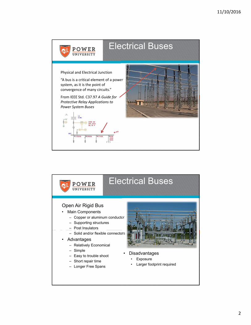
Physical and Electrical Junction
“A bus is a critical element of a power system, as it is the point of convergence of many circuits.”
From IEEE Std. C37.97 A Guide for Protective Relay Applications to Power System Buses
Open Air Rigid Bus• Main Components
– Copper or aluminum conductor
– Supporting structures
– Post Insulators
– Solid and/or flexible connectors
• Advantages– Relatively Economical
– Simple
– Easy to trouble shoot
– Short repair time
– Longer Free Spans
Electrical Buses
• Disadvantages• Exposure
• Larger footprint required
11/10/2016
3
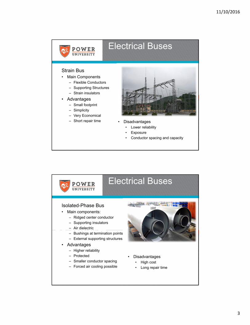
Strain Bus• Main Components
– Flexible Conductors
– Supporting Structures
– Strain insulators
• Advantages– Small footprint
– Simplicity
– Very Economical
– Short repair time
Electrical Buses
• Disadvantages• Lower reliability
• Exposure
• Conductor spacing and capacity
Isolated-Phase Bus• Main components:
– Ridged center conductor
– Supporting insulators
– Air dielectric
– Bushings at termination points
– External supporting structures
• Advantages– Higher reliability
– Protected
– Smaller conductor spacing
– Forced air cooling possible
Electrical Buses
• Disadvantages• High cost
• Long repair time
11/10/2016
4
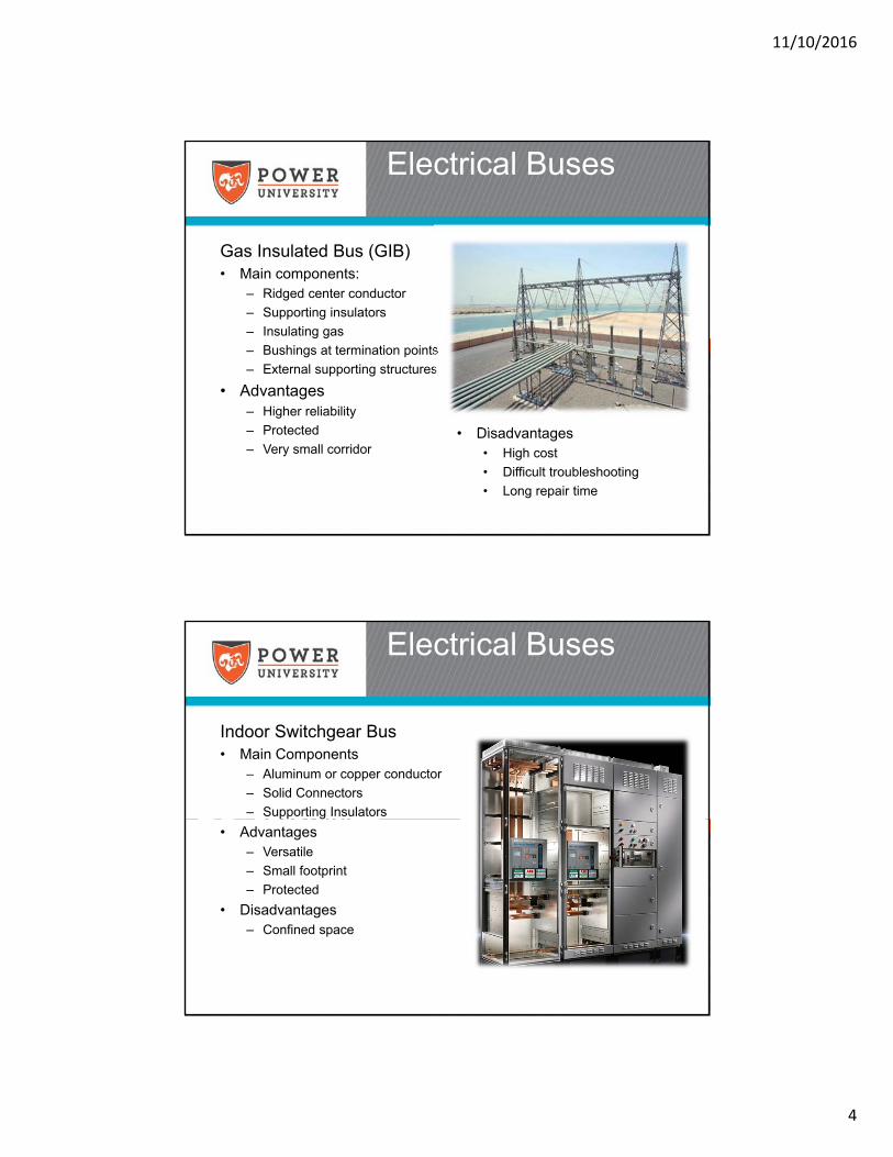
Gas Insulated Bus (GIB)• Main components:
– Ridged center conductor
– Supporting insulators
– Insulating gas
– Bushings at termination points
– External supporting structures
• Advantages– Higher reliability
– Protected
– Very small corridor
Electrical Buses
• Disadvantages• High cost
• Difficult troubleshooting
• Long repair time
Indoor Switchgear Bus• Main Components
– Aluminum or copper conductor
– Solid Connectors
– Supporting Insulators
• Advantages– Versatile
– Small footprint
– Protected
• Disadvantages– Confined space
Electrical Buses
11/10/2016
5
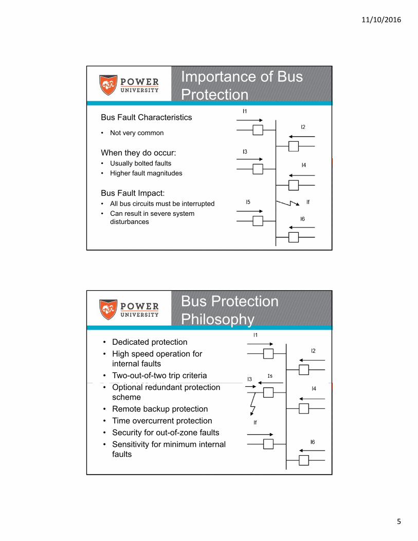
Bus Fault Characteristics
• Not very common
When they do occur:• Usually bolted faults
• Higher fault magnitudes
Bus Fault Impact:• All bus circuits must be interrupted
• Can result in severe system disturbances
Importance of Bus Protection
• Dedicated protection
• High speed operation for internal faults
• Two-out-of-two trip criteria
• Optional redundant protection scheme
• Remote backup protection
• Time overcurrent protection
• Security for out-of-zone faults
• Sensitivity for minimum internal faults
Bus Protection Philosophy
11/10/2016
6
Principle and Operation• Trips and lockouts the bus
breakers
• Many output contacts
• Operation isolates its trip coil
• Very fast operation
• Hardwired to breaker trip circuits
• Can be used to protect relay contacts
Bus Lockout Relays
• Improves system reliability
• Minimizes Impact of Outages
• Various Arrangements– Combined Arrangements
– Operating Flexibility
– Selectivity
– Bus protection must adapt
Bus Sectionalizing
11/10/2016
7
• One of the most basic and economical designs
• No operating flexibility
• No selectivity
• Zone of Protection: Encompasses the whole bus.
• Bus fault will interrupt all associated services
Single Bus – Single Breaker
• Zone of Protection: Bus and Transformer protection is combined.
• Usually used in distribution substations
• No selectivity
• No flexibility
• Fault location difficulty
• Very economical
Bus & Transformer –Single Breaker
11/10/2016
8
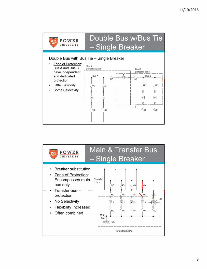
Double Bus with Bus Tie – Single Breaker
Double Bus w/Bus Tie – Single Breaker
• Zone of Protection: Bus A and Bus B have independent and dedicated protection.
• Little Flexibility
• Some Selectivity
Main & Transfer Bus – Single Breaker
• Breaker substitution
• Zone of Protection: Encompasses main bus only.
• Transfer bus protection
• No Selectivity
• Flexibility Increased
• Often combined
11/10/2016
9
Double Bus – Single Breaker
• Zone of Protection: Bus 1 and Bus 2 have independent protection assigned based on switching condition.
• Lots of operating flexibility
• Some selectivity
• Complex switching
• CT winding assignments change
• Not commonly used in the U.S.
Double Bus – Double Breaker
• Zone of Protection: Bus 1 and Bus 2 have independent protection
• Full operating flexibility
• Improved Selectivity
• Increased cost
• Very common
11/10/2016
10
Ring Bus
• No dedicated bus protection
• Full operating flexibility
• Good selectivity
• Shared breakers
• Economical
Breaker-And-A-Half Bus
• Full operating flexibility
• Excellent selectivity
• Widely used
• Zone of Protection: Bus A and Bus B have independent and dedicated protection zones.
• Line position protection provided by branch circuits
• Economical
11/10/2016
11
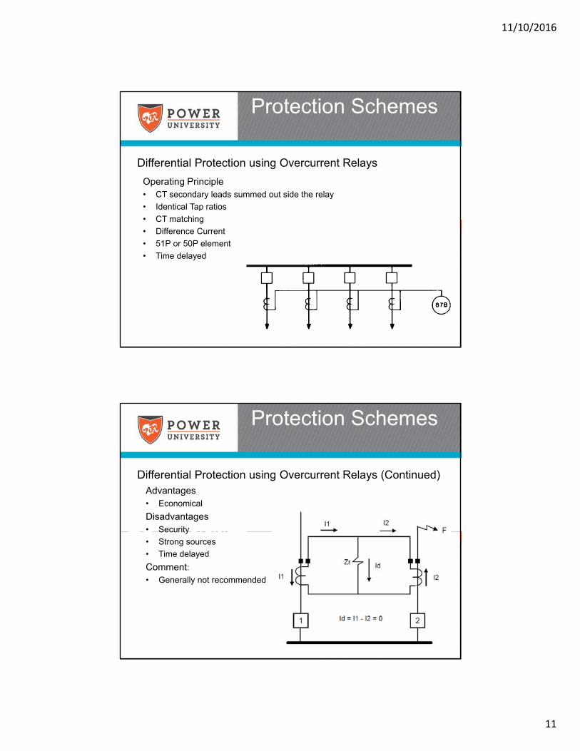
Differential Protection using Overcurrent Relays
Protection Schemes
Operating Principle• CT secondary leads summed out side the relay
• Identical Tap ratios
• CT matching
• Difference Current
• 51P or 50P element
• Time delayed
Advantages • Economical
Disadvantages• Security
• Strong sources
• Time delayed
Comment:• Generally not recommended
Differential Protection using Overcurrent Relays (Continued)
Protection Schemes
11/10/2016
12
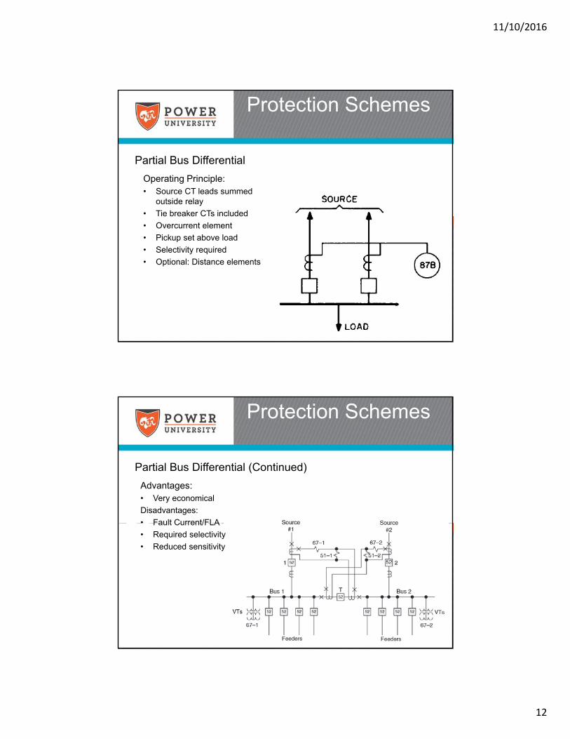
Partial Bus Differential
Protection Schemes
Operating Principle: • Source CT leads summed
outside relay
• Tie breaker CTs included
• Overcurrent element
• Pickup set above load
• Selectivity required
• Optional: Distance elements
Partial Bus Differential (Continued)
Protection Schemes
Advantages: • Very economical
Disadvantages:
• Fault Current/FLA
• Required selectivity
• Reduced sensitivity
11/10/2016
13
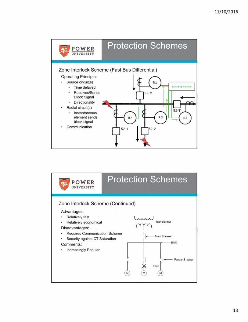
Zone Interlock Scheme (Fast Bus Differential)
Protection Schemes
Operating Principle:• Source circuit(s)
• Time delayed
• Receives/Sends Block Signal
• Directionality
• Radial circuit(s)
• Instantaneous element sends block signal
• Communication
Zone Interlock Scheme (Continued)
Protection Schemes
Advantages:• Relatively fast
• Relatively economical
Disadvantages:• Requires Communication Scheme
• Security against CT Saturation
Comments:• Increasingly Popular
11/10/2016
14
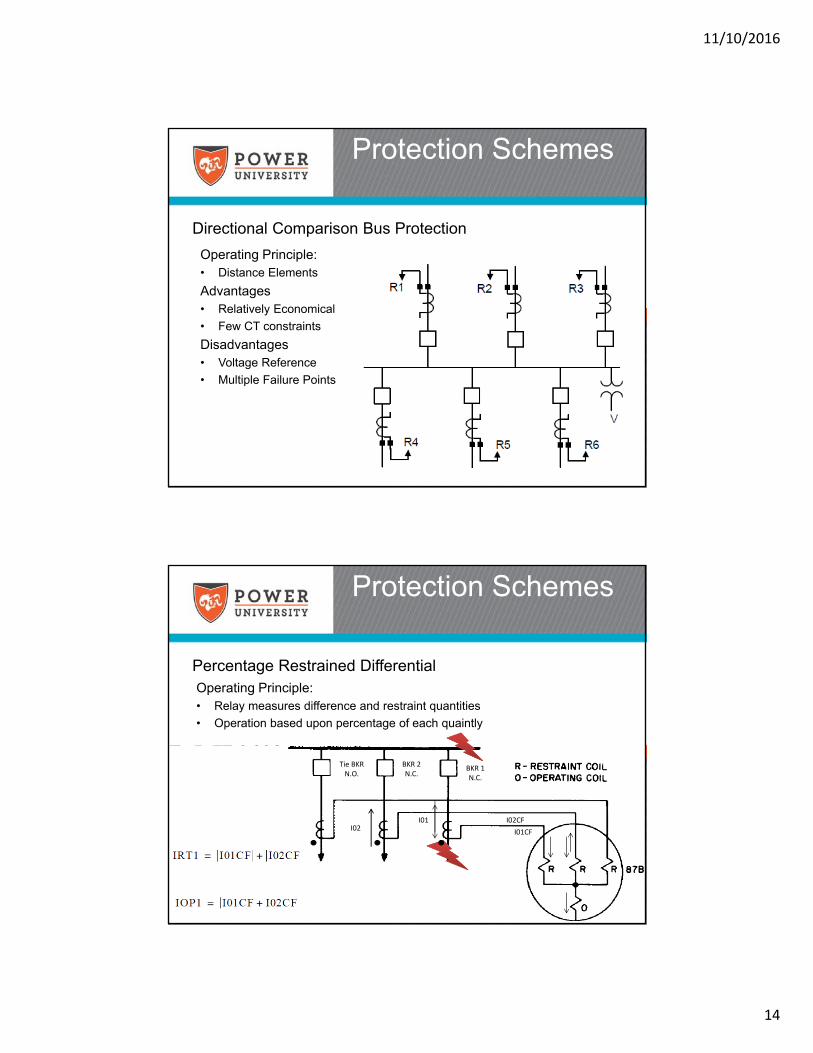
Directional Comparison Bus Protection
Protection Schemes
Operating Principle:• Distance Elements
Advantages• Relatively Economical
• Few CT constraints
Disadvantages• Voltage Reference
• Multiple Failure Points
Percentage Restrained Differential
Protection Schemes
Operating Principle:• Relay measures difference and restraint quantities
• Operation based upon percentage of each quaintly
Tie BKR N.O.
I01CF
I02CFI01I02
BKR 2N.C.
BKR 1N.C.
11/10/2016
15
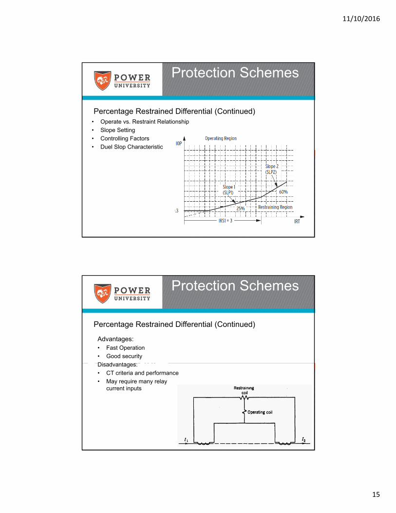
Percentage Restrained Differential (Continued)
Protection Schemes
• Operate vs. Restraint Relationship
• Slope Setting
• Controlling Factors
• Duel Slop Characteristic
Percentage Restrained Differential (Continued)
Protection Schemes
Advantages:• Fast Operation
• Good security
Disadvantages:
• CT criteria and performance
• May require many relay current inputs
11/10/2016
16
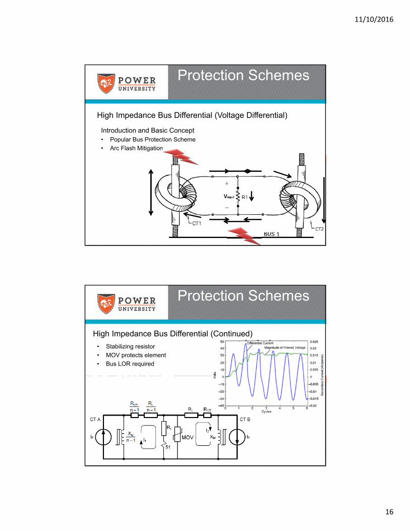
High Impedance Bus Differential (Voltage Differential)
Protection Schemes
Introduction and Basic Concept• Popular Bus Protection Scheme
• Arc Flash Mitigation
VsmallVbig
High Impedance Bus Differential (Continued)
Protection Schemes
• Stabilizing resistor
• MOV protects element
• Bus LOR required
11/10/2016
17
High Impedance Bus Differential (Continued)
Protection Schemes
• SEL 587Z Relay
• Uses a 2000Ω resistor
• MOV size options
• SEL Recommended Settings (Per AN2008-01)
• Vs setting of 200V
• Optional Time Delayed Setting
High Impedance Bus Differential (Continued)
Protection Schemes
Manufacturer Internal Fault Testing• Test currents of 20 kA, 40 kA and 60 kA applied.
• Heavy CT saturation observed
11/10/2016
18
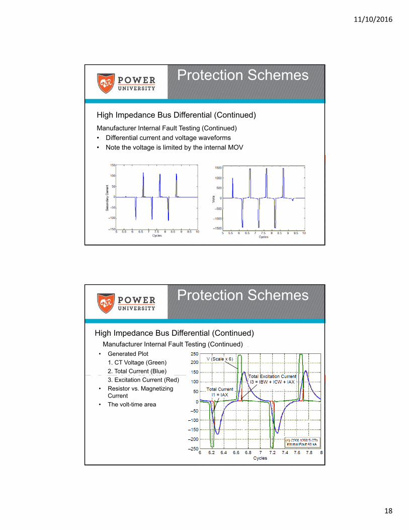
High Impedance Bus Differential (Continued)
Protection Schemes
Manufacturer Internal Fault Testing (Continued)
• Differential current and voltage waveforms
• Note the voltage is limited by the internal MOV
High Impedance Bus Differential (Continued)
Protection Schemes
Manufacturer Internal Fault Testing (Continued)
• Generated Plot
1. CT Voltage (Green)
2. Total Current (Blue)
3. Excitation Current (Red)
• Resistor vs. Magnetizing Current
• The volt-time area
11/10/2016
19
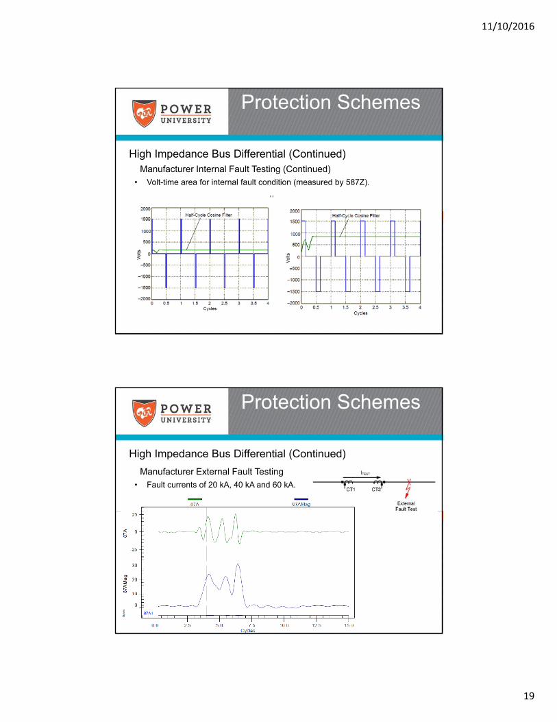
Manufacturer Internal Fault Testing (Continued)
• Volt-time area for internal fault condition (measured by 587Z).
High Impedance Bus Differential (Continued)
Protection Schemes
High Impedance Bus Differential (Continued)
Manufacturer External Fault Testing
• Fault currents of 20 kA, 40 kA and 60 kA.
Protection Schemes
11/10/2016
20
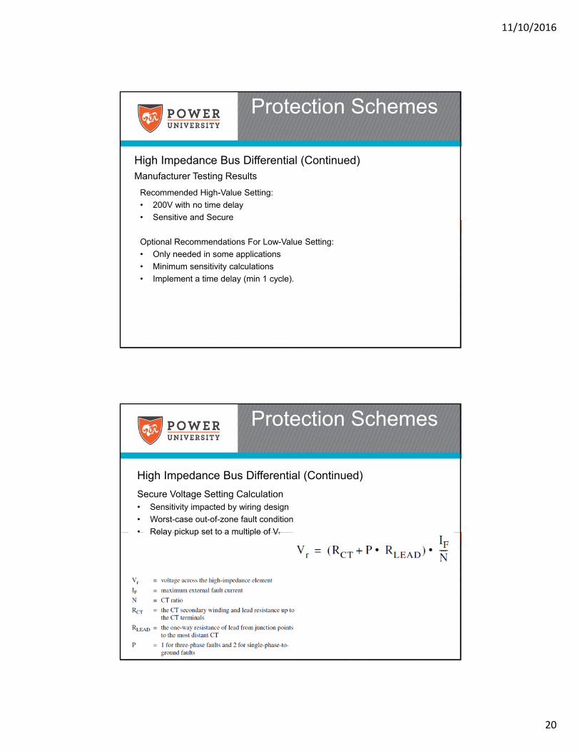
High Impedance Bus Differential (Continued)
Protection Schemes
Manufacturer Testing Results
Recommended High-Value Setting:
• 200V with no time delay
• Sensitive and Secure
Optional Recommendations For Low-Value Setting:
• Only needed in some applications
• Minimum sensitivity calculations
• Implement a time delay (min 1 cycle).
High Impedance Bus Differential (Continued)
Protection Schemes
Secure Voltage Setting Calculation• Sensitivity impacted by wiring design
• Worst-case out-of-zone fault condition
• Relay pickup set to a multiple of Vr
11/10/2016
21
High Impedance Bus Differential (Continued)
Protection Schemes
Minimum Sensitivity Calculation• Verify for Internal Fault
• Ignore MOV leakage current
• CT Excitation Characteristic
High Impedance Bus Differential (Conclusion)
Protection Schemes
Advantages
• Very fast operation
• High security
Disadvantages
• Important CT criteria
• Sensitivity
bjohnson
Typewriter
Ie calculated for Vs/2 Ir calculated for Vs
11/10/2016
22
• Bus protection is critical
• Bus Sectionalizing– Operating flexibility
– Selectivity
• Bus Protection Schemes– Differential Variant Recommended
• High Impedance Bus differential– Resistor element across CT
summation junction
– Pickup in terms of Voltage
– CT Saturation is not a concern
– Sensitivity should be verified
Summary
• IEEE Std. C37.97, Guide for Protective Relay Applications to Power Buses.
• Blackburn, J. Lewis, Protective Relaying, Principles and Applications, Third Edition, New York: Marcel Dekker, 1998.
• Basler Electric Company, Bus Protective Relaying, Methods and Application, Revision Date: 6-8-2005
• General Electric Company, Bus Differential Protection, WPRC 1995, GER-3961
• Zocholl, E. Stanley and Costello, David, Schweitzer Engineering Laboratories, Inc., Application Guidelines for Microprocessor-Based, High-Impedance Bus Differential Relays
• Costello, David and Mooney, Joe, Applying the SEL-587Z in Switchgear, SEL Application Note AN2008-01
References
11/10/2016
23
Thank you for your time!
This concludes the educational content of this activity.