Introduction to electrical and mechanical power measurement CYCLE-BASED POWER CALCULATIONS FOR ELECTRICAL AND MECHANICAL QUANTITIES René Bastiaanssen Business Development Manager Electric Power Testing
Transcript
Introduction to electrical and mechanical power measurementCYCLE-BASED POWER CALCULATIONS FOR ELECTRICAL AND MECHANICAL QUANTITIES
René BastiaanssenBusiness Development ManagerElectric Power Testing
Agenda
UNRESTRICTED2
1. Measuring the basics, voltage and current input methods
2. Sampling rate and fundamental power
3. Averaging in power calculations
4. Dynamic power measurement
5. Mechanical power measurement
6. Accuracy vs dynamic in mechanical power measurement
7. Cyle based electrical power vs instantaneous torque
8. Cycle based efficiency calculation
9. summary
UNRESTRICTED3
Measuring the basicsvoltage and current input methods
UNRESTRICTED4
Our theoretical Device Under Test today
Frequency inverterDC power source TransmissionElectrical machine
Voltage measurements at different voltage levels (recap)
5
• Direct voltage inputs up to +/- 1500 V DC˗ 0.015% + 0.02% accuracy˗ Phase to phase or phase to (artificial) star
• 5 kV differential probe˗ 0.1% accuracy˗ Certified and always USER safe
• Higher voltages up to 20 kV including isolation ->Fiber optical isolated
front ends paired with HV dividersUNRESTRICTED
Current measurement methods (recap)
6
Zero-Flux Current transformer• High accuracy and medium bandwidth
• Some effort in installation (circuit needs to be opened)
• Connected using burden resistors
Current clamps or Rogowski coils• Low accuracy and high bandwidth
• Rogowski coils -> AC only
• Easy to install
UNRESTRICTED
UNRESTRICTED7
Sampling rate and fundamental power
8
Fundamental matters for useful power
Current sensor bandwidth as limiting factor
Catching rise time Not for power measurement
If we do want to catch the switching behavior of the inverter components, sample rates >100MS/s
Sampling Rate
UNRESTRICTED
9
DC Battery Voltage & Current
Three Phase inverter Voltage & Current
These are our inputs for the electric power calculations
Simple multiplication?
From measured signals to results Could the inverter cause a challenge?
UNRESTRICTED
10
Point by point multiplication gives high frequency results
“Instant power” is not useful• No steady values• Positive to negative power swings• Power swings at inverter frequency˗ 3 phase power
˗ DC power
Calculating “Instant” Power
UNRESTRICTED
11
AC from inverter is coupled to the DC from the battery or source
High frequency content because of inverter switching
How to average this?• Filter?• RMS?• Mean?
How to calculate power?
DC Inverter input – Not true DC
UNRESTRICTED
12
4A AC added to a 10A DC gives a good example of why we need to measure correctly
Average voltage and current• Mean averages the AC out of
the value if the average is periodic• RMS includes the AC value
Power• u_mean*i_mean No AC accounted for in power• U_RMS*I_RMS No Phase accounted for in power• Mean(u_1*i_1) Correct Power for correct period
Calculating DC Average and DC Power
Phase offset of AC components
UNRESTRICTED
13
PWM driven inverter has high frequency switches creating a sinusoidal voltage
Current is a result of this high frequency sinusoidal voltage
Considerations:• Phase shift between Voltage
and Current• Reactive and apparent power• RMS Period
AC Inverter output – phase shifted and distorted signals
UNRESTRICTED
14
RMS Voltage * RMS current does not give real power• Phase offset needs to be accounted for• Real Power P = Mean(voltage*current)• Apparent Power S = Vrms* Irms• Reactive Power Q = sqrt(S^2-P^2)˗ Averaging basis also effects angle measurement
Calculation also based on cycle period
Calculating Real Power
– Current– Voltage
– Random Averaging Period– Cycle based averaging period
– RMS based on random averaging period– RMS based synchronous averaging period
– Random S– Cycle based S
UNRESTRICTED
UNRESTRICTED15
Averaging in power calculations
16
Voltage with an asymmetrical ripple
A random averaging period (Black) will give an RMS/average with an asymmetric signal• Black RMS bouncing around depending on average period
A cycle based averaging period (RED) is used to capture the whole asymmetric event• Red RMS measurement is constant
Averaging Period Matters
– Voltage– Random averaging period – Sync Averaging period
– RMS based on random averaging period
– RMS based synchronous averaging period
UNRESTRICTED
17
Characterize AC signals with RMS calculation
RMS calculation can be done on any• Random• Rotational• Cycle based
Not all time basis will give a correct output• Only Cycle based or increments
of cycle based give a proper output
RMS shown for Cycle based and Random calculation periods
RMS Periods matter
– Current
– Random Averaging Period– Cycle based averaging period
– RMS based on random averaging period– RMS based synchronous averaging period
UNRESTRICTED
Conventional power analyzers use “Analog” PLL-based cycle detection• Problem: This only works in steady state load conditions
The HBM eDrive system detects the cycles in real time using advanced digital algorithms• Then the power calculations are executed over a half cycle (or any multiple of this)• This delivers all cycle and thus accurate power results also in dynamic load changes
eDrive: Cycle detection – the key to correct power readings
Current trace used for Cycle detection (green) and resulting “CycleMaster” trace (red)
eDrive Cycle detection working during machine startup at rapidly changing fundamental frequencies
UNRESTRICTED18
UNRESTRICTED19
Dynamic power measurement
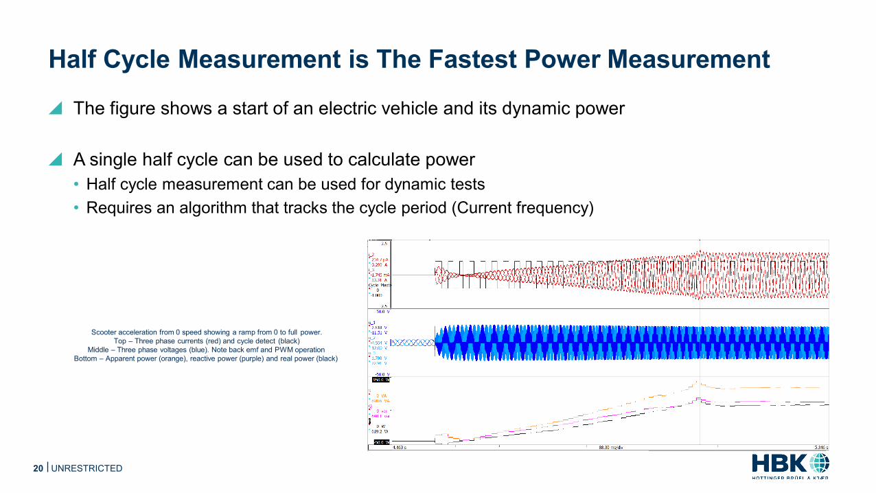
The figure shows a start of an electric vehicle and its dynamic power
A single half cycle can be used to calculate power• Half cycle measurement can be used for dynamic tests• Requires an algorithm that tracks the cycle period (Current frequency)
Half Cycle Measurement is The Fastest Power Measurement
Scooter acceleration from 0 speed showing a ramp from 0 to full power.Top – Three phase currents (red) and cycle detect (black)
Middle – Three phase voltages (blue). Note back emf and PWM operation Bottom – Apparent power (orange), reactive power (purple) and real power (black)
UNRESTRICTED20
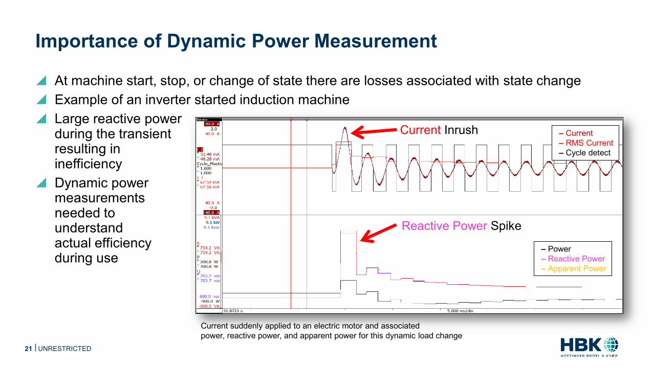
At machine start, stop, or change of state there are losses associated with state change Example of an inverter started induction machine Large reactive power
during the transient resulting in inefficiency
Dynamic power measurements needed to understand actual efficiency during use
Importance of Dynamic Power Measurement
Current suddenly applied to an electric motor and associated power, reactive power, and apparent power for this dynamic load change
Reactive Power Spike
Current Inrush
– Power– Reactive Power– Apparent Power
– Current– RMS Current– Cycle detect
UNRESTRICTED21
Increased losses in dynamic situations makes drive cycle testing necessary
Testing the system the way a user will do this; this gives accurate range estimations
Cycle based power analyzer can accurately measure dynamic power
Understand control behavior to disturbances
Dynamic power is needed to optimize the machine controller
Real World Load Test Dynamics
Dynamic signals from laps around a track on an electric scooter. Including: starts, stops, coasts, uphills and downhills
– Instantaneous Signals– RMS Signals
– Power– Reactive Power– Apparent Power
UNRESTRICTED22
UNRESTRICTED23
Mechanical power measurement
UNRESTRICTED24
Torque transducers details• Measurement body –> straingage-> bridge amplifier -> telemetry -> DAQ• Any speed transducer
Signal interfaces• Analog?• Digital?
Torque measurement (recap)
UNRESTRICTED25
Advantages frequency output:• Accurate (Differential transmission no noise, no drift)• Easy to T-off
Consideration: Electronics (Counter) needed to convert frequency back to torque• Counter inputs have a systematic error based on time limits
˗ Short counting time gives dynamic torque but larger error˗ Long counting time gives accurate torque but less dynamic signal˗ Higher centre frequency (for 0 Nm) gives higher accuracy and better dynamic range
Frequency output for torque transducers (recap)
UNRESTRICTED26
Cyle based electrical power vs instantaneous torque
UNRESTRICTED27
Shown below results:• cycle based electrical power measurement• Instantaneous torque and speed used to calculate mechanical power• Efficiency calculated based on these results
What does this mean?
Cyle based electrical power vs instantaneous torque
UNRESTRICTED28
Cycle based efficiency calculation
UNRESTRICTED29
Better: use cycle base from electrical power calculation as averaging period for mechanicalpower
Example of cycle based electrical and mechanical power and derived efficiencies. Effect of averaging on MU
Cycle based efficiency calculation
UNRESTRICTED30
Same approach allows us to track effects on a system level• How does a load step influence the inverter and motor individually• What does this mean on a system level• Losses
Cycle based calculations on a system level
UNRESTRICTED31
Summary
Fast and Accurate - Power is Calculated on a ½ Cycle Basis
To compute any power result the “cycles” of the signals are needed
The eDrive hardware detects the cycles using advanced digital algorithms in a DSP
RMS values, power, efficiency, and advanced calculations are done on the cycle basis• Allows for dynamic testing• Highly dynamic raw signals available in
parallel for other purposes as e.g. NVH analysis
Accuracy 0.015% +0.02% • And Auto Range
Current –Cycle Detect –
Current and cycle detect for a single phase of a 3-phase system. This highlights the cycle detect identifying ½ cycles for calculation.
3232 UNRESTRICTED
Dynamic Testing with Cycle Detect
Transient power measurements allows to dynamically measure efficiency
Cycle detect allows measurement of signals as frequency is changing
Dynamic testing allows to characterize real world scenarios
Measure power accurately during frequency changes
Current –Voltage –Power –Reactive Power –Apparent Power –
Vehicle acceleration from 0 to full speed showing a ramp from 0 to full power.
33 UNRESTRICTED33
Auditable Testing – All data recorded & public equations
eDrive stores all signals to hard disk at 2 MS/s per channel
Calculated power results have the data to support them
Correlate tests to models
Execute equations in real time to cut down post process time
Current and voltage for a 3-phase machine. Line to line voltage measurements are shown.
Current –Voltage –
34
Power calculations done with public formulas. User formulas can be added.


![Measurement of electrical resistance and mechanical … BUREAUOFSTANDARDS GeorgeK.Burgess,Director TECHNOLOGICPAPERSOFTHEBUREAUOFSTANDARDS,No.271 [PartofVol.18] MEASUREMENTOFELECTRICAL](https://static.documents.pub/doc/80x56/5b0074fd7f8b9a6a2e8ca9be/measurement-of-electrical-resistance-and-mechanical-bureauofstandards-georgekburgessdirector.jpg)


