PIPE 6014 1 Introduction to Piping and Pipe Fittings Learning Outcome When you complete this module you will be able to: Discuss the basic types of piping, pipe connections, supports, drainage devices and insulation. Learning Objectives Here is what you will be able to do when you complete each objective: 1. State the applications for the most common materials used in piping. 2. Describe the common methods used to identify the size of commercial pipe. 3. Describe methods of connection for screwed, flanged and welded pipe and identify fittings and their markings. 4. Describe methods and devices used to allow for pipe expansion and support. 5. Explain the need for good drainage of steam piping and describe separators and steam traps. Explain water hammer. 6. Explain the need for piping insulation and describe materials and methods of insulation.
Transcript
PIPE 6014 1
Introduction to Piping and Pipe Fittings
Learning Outcome When you complete this module you will be able to:
Discuss the basic types of piping, pipe connections, supports, drainage devices and insulation.
Learning Objectives Here is what you will be able to do when you complete each objective:
1. State the applications for the most common materials used in piping. 2. Describe the common methods used to identify the size of commercial pipe.
3. Describe methods of connection for screwed, flanged and welded pipe and identify fittings and their markings.
4. Describe methods and devices used to allow for pipe expansion and support.
5. Explain the need for good drainage of steam piping and describe separators and steam traps. Explain water hammer.
6. Explain the need for piping insulation and describe materials and methods of
insulation.
PIPE 6014 2
INTRODUCTION Piping is used in power plants to convey fluids to and from their place of usage and forms an essential part of the operation of the plant. It is advantageous for the student at Fourth Class level to understand the differences between piping requirements for the various fluids concerned, the materials best to be used, commercial pipe sizes, methods of connection and fittings. PIPING MATERIALS The material to be used for pipe manufacture must be chosen to suit the operating conditions of the piping system. Guidance in selecting the correct material can be obtained from standard piping codes. As an example, the ASME Code for Pressure Piping contains sections on Power Piping, Industrial Gas and Air Piping, Refinery and Oil Piping, and Refrigeration Piping Systems. The object being to ensure that the material used is entirely safe under the operating conditions of pressure, temperature, corrosion, and erosion expected. Some of the materials most commonly used for power plant piping are discussed in the following sections. Steel Steel is the most frequently used material for piping. Forged steel is extensively used for fittings while cast steel is primarily used for special applications. Pipe is manufactured in two main categories - seamless and welded. Cast Iron Cast iron has a high resistance to corrosion and to abrasion and is used for ash handling systems, sewage lines and underground water lines. It is, however, very brittle and is not suitable for most power plant services. It is made in different grades such as gray cast iron, malleable cast iron and ductile cast iron. Brass and Copper Non-ferrous material such as copper and copper alloys are used in power plants in instrumentation and water services where temperature is not a prime factor.
PIPE 6014 3
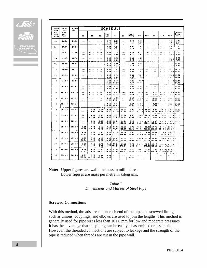
COMMERCIAL PIPE SIZES Commercial pipe is made in standard sizes each having several different wall thicknesses or weights. Up to and including 304.8 mm pipe, the size is expressed as nominal (approximate) inside diameter. Above 304.8 mm, the size is given as the actual outside diameter. All classes of pipe of a given size have the same outside diameter, with the extra thickness for different weights on the inside. For example, if a pipe was designated as 152.4 mm size this would mean that it has a nominal or approximate inside diameter of 152.4 mm. The outside diameter is 168.28 mm. This is a constant value no matter what the wall thickness is. The actual inside diameter of the pipe will depend upon its wall thickness. For a standard wall thickness, the actual inside diameter of 152.4 mm pipe is 154.06 mm. For an extra strong wall thickness, the actual inside diameter is 146.34 mm. There are two systems used to designate the various wall thicknesses of different sizes of pipe. The older method lists pipe as standard (S), extra strong (XS) and double extra strong (XXS). The newer method, which is superseding the older method, uses schedule numbers to designate wall thickness. These numbers are 10, 20, 30, 40, 60, 80, 100, 120, 140 and 160. In most sizes of pipe, schedule 40 corresponds to standard and schedule 80 corresponds to extra strong. Table 1 lists the dimensions and the mass in kg/m of different sizes of steel pipe with varying wall thicknesses. METHODS OF CONNECTING PIPE There are three general methods used to join or connect lengths of pressure piping. These include:
1. Using threaded pipe and screwed connections. 2. Using flanges. 3. Using welded joints.
Each of these methods has certain advantages and disadvantages and each will be discussed in the following sections.
AK_1_0_1a.jpg G
AK_1_0_1b.jpg G
AK_1_0_1c.jpg G
PIPE 6014 4
Note: Upper figures are wall thickness in millimetres. Lower figures are mass per metre in kilograms.
Table 1
Dimensions and Masses of Steel Pipe Screwed Connections With this method, threads are cut on each end of the pipe and screwed fittings such as unions, couplings, and elbows are used to join the lengths. This method is generally used for pipe sizes less than 101.6 mm for low and moderate pressures. It has the advantage that the piping can be easily disassembled or assembled. However, the threaded connections are subject to leakage and the strength of the pipe is reduced when threads are cut in the pipe wall.
PIPE 6014 5
Fig. 1 illustrates various screwed fittings that may be used when fabricating a pipe system.
Figure 1 Threaded Pipe Fittings
The purposes of the fittings illustrated in Fig. 1 may be generally stated as follows: Elbows - for making angle turns in piping. Nipples - for making close connections. They are threaded on both ends with the close nipple threaded for its entire length. Couplings - for connecting two pieces of pipe of the same size in a straight line. Unions - for providing an easy method for dismantling piping. Tees and Crosses - for making branch line connections at 90°. Y-bends - for making branch line connections at 45°. Return Bends - for reversing direction of a pipe run. Plugs and Caps - for closing off open pipe ends or fittings.
AK_1_0_2.jpg G
AK_1_0_4.jpg G
AK_1_0_5.jpg G
AK_1_0_6.jpg G
AK_1_0_46.mov V
AK_1_0_9.jpg G
PIPE 6014 6
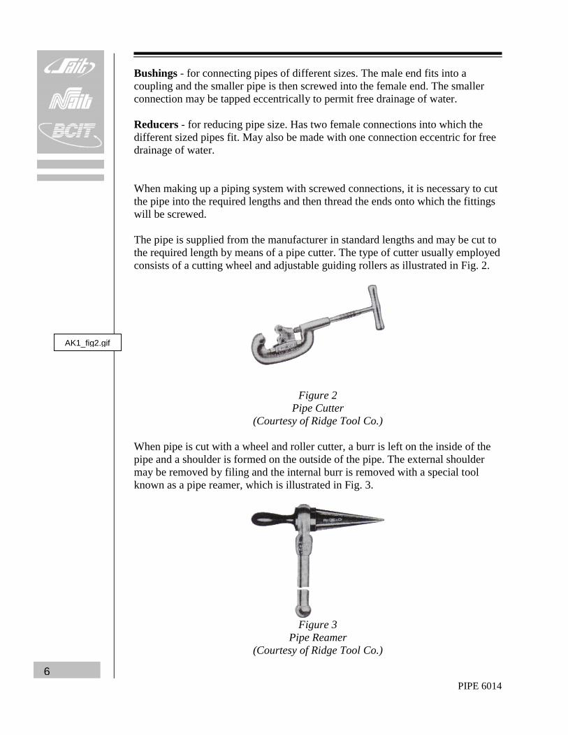
Bushings - for connecting pipes of different sizes. The male end fits into a coupling and the smaller pipe is then screwed into the female end. The smaller connection may be tapped eccentrically to permit free drainage of water. Reducers - for reducing pipe size. Has two female connections into which the different sized pipes fit. May also be made with one connection eccentric for free drainage of water. When making up a piping system with screwed connections, it is necessary to cut the pipe into the required lengths and then thread the ends onto which the fittings will be screwed. The pipe is supplied from the manufacturer in standard lengths and may be cut to the required length by means of a pipe cutter. The type of cutter usually employed consists of a cutting wheel and adjustable guiding rollers as illustrated in Fig. 2.
Figure 2 Pipe Cutter
(Courtesy of Ridge Tool Co.) When pipe is cut with a wheel and roller cutter, a burr is left on the inside of the pipe and a shoulder is formed on the outside of the pipe. The external shoulder may be removed by filing and the internal burr is removed with a special tool known as a pipe reamer, which is illustrated in Fig. 3.
Figure 3
Pipe Reamer (Courtesy of Ridge Tool Co.)
AK1_fig2.gif
PIPE 6014 7
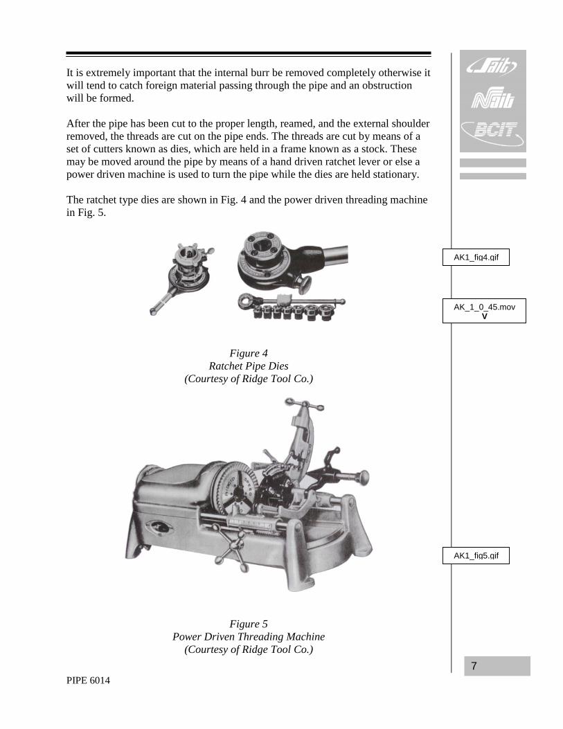
It is extremely important that the internal burr be removed completely otherwise it will tend to catch foreign material passing through the pipe and an obstruction will be formed. After the pipe has been cut to the proper length, reamed, and the external shoulder removed, the threads are cut on the pipe ends. The threads are cut by means of a set of cutters known as dies, which are held in a frame known as a stock. These may be moved around the pipe by means of a hand driven ratchet lever or else a power driven machine is used to turn the pipe while the dies are held stationary. The ratchet type dies are shown in Fig. 4 and the power driven threading machine in Fig. 5.
Figure 4 Ratchet Pipe Dies
(Courtesy of Ridge Tool Co.)
Figure 5 Power Driven Threading Machine
(Courtesy of Ridge Tool Co.)
AK1_fig4.gif
AK1_fig5.gif
AK_1_0_45.mov V
PIPE 6014 8
Flanged Connections This method uses flanges, which are bolted together, face to face, usually with a gasket between the two faces. Flanged connections have the advantage over welded connections of permitting disassembly and are more convenient to assemble and disassemble than the screwed connections. There are three general types of pipe flanges used and these are classified according to the method of attaching to the pipe end. These types are the screwed flange, the welded flange and the loose or lapped Van Stone flange and are illustrated in Fig. 6. Note that two types of welded flanges are shown; the slip-on weld and the weld-neck type. In the weld-neck type, the hub of the flange is butt welded to the pipe whereas the slip-on flange is attached by two fillet welds. Van Stone flanges are used in piping systems constructed from stainless steel or other costly materials. The flanges in the system are usually of carbon steel. In the Van Stone type, the flange fits loosely on the pipe and the pipe end is lapped over and faced off as shown in the figure. The pipe to be connected is similarly lapped and has a loose companion flange. A gasket is used between the two lapped faces of the pipes.
Figure 6 Pipe Flange Types
AK_1_0_10.jpg G
AK_1_0_11.jpg G
AK_1_0_12.jpg G
AK_1_0_13.gif G
AK_1_0_14.gif G
AK_1_0_15.gif G
AK_1_0_16.gif G
AK_1_0_17.gif G
AK1_fig6.gif
PIPE 6014 9
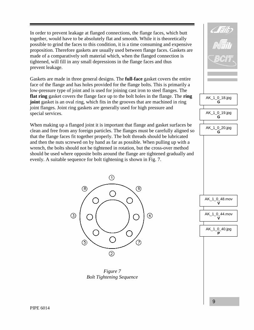
In order to prevent leakage at flanged connections, the flange faces, which butt together, would have to be absolutely flat and smooth. While it is theoretically possible to grind the faces to this condition, it is a time consuming and expensive proposition. Therefore gaskets are usually used between flange faces. Gaskets are made of a comparatively soft material which, when the flanged connection is tightened, will fill in any small depressions in the flange faces and thus prevent leakage. Gaskets are made in three general designs. The full-face gasket covers the entire face of the flange and has holes provided for the flange bolts. This is primarily a low-pressure type of joint and is used for joining cast iron to steel flanges. The flat ring gasket covers the flange face up to the bolt holes in the flange. The ring joint gasket is an oval ring, which fits in the grooves that are machined in ring joint flanges. Joint ring gaskets are generally used for high pressure and special services. When making up a flanged joint it is important that flange and gasket surfaces be clean and free from any foreign particles. The flanges must be carefully aligned so that the flange faces fit together properly. The bolt threads should be lubricated and then the nuts screwed on by hand as far as possible. When pulling up with a wrench, the bolts should not be tightened in rotation, but the cross-over method should be used where opposite bolts around the flange are tightened gradually and evenly. A suitable sequence for bolt tightening is shown in Fig. 7.
Figure 7 Bolt Tightening Sequence
AK_1_0_18.jpg G
AK_1_0_19.jpg G
AK_1_0_20.jpg G
AK_1_0_44.mov V
AK_1_0_40.jpg P
AK_1_0_48.mov V
PIPE 6014 10
Welded Connections In this method, the pipe lengths are welded directly to one another and directly to any valves or fittings that may be required. The use of these welded joints for piping has several advantages over the use of screwed connections or flanged connections:
1. The possibility of leakage is removed with the elimination of screwed or flanged joints.
2. The weight of the piping system is reduced due to the elimination of
connecting flanges or fittings.
3. The cost of material and the need for maintenance are reduced with the elimination of flanges and fittings.
4. The piping looks neater and is easier to insulate with the elimination of
bulky flanges and fittings.
5. Welded joints give more flexibility to the piping design as the pipes may be joined at practically any angle to each other.
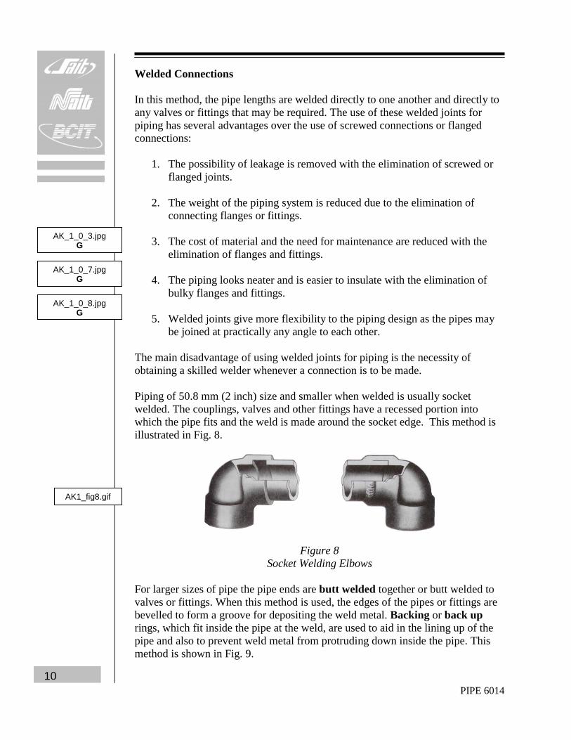
The main disadvantage of using welded joints for piping is the necessity of obtaining a skilled welder whenever a connection is to be made. Piping of 50.8 mm (2 inch) size and smaller when welded is usually socket welded. The couplings, valves and other fittings have a recessed portion into which the pipe fits and the weld is made around the socket edge. This method is illustrated in Fig. 8.
Figure 8 Socket Welding Elbows
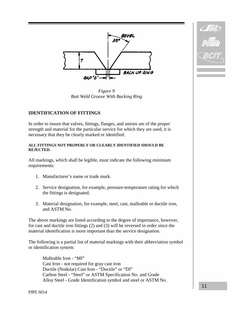
For larger sizes of pipe the pipe ends are butt welded together or butt welded to valves or fittings. When this method is used, the edges of the pipes or fittings are bevelled to form a groove for depositing the weld metal. Backing or back up rings, which fit inside the pipe at the weld, are used to aid in the lining up of the pipe and also to prevent weld metal from protruding down inside the pipe. This method is shown in Fig. 9.
AK_1_0_3.jpg G
AK_1_0_7.jpg G
AK_1_0_8.jpg G
AK1_fig8.gif
PIPE 6014 11
Figure 9 Butt Weld Groove With Backing Ring
IDENTIFICATION OF FITTINGS In order to insure that valves, fittings, flanges, and unions are of the proper strength and material for the particular service for which they are used, it is necessary that they be clearly marked or identified. ALL FITTINGS NOT PROPERLY OR CLEARLY IDENTIFIED SHOULD BE REJECTED. All markings, which shall be legible, must indicate the following minimum requirements:
1. Manufacturer’s name or trade mark.
2. Service designation, for example, pressure-temperature rating for which the fittings is designated.
3. Material designation, for example, steel, cast, malleable or ductile iron,
and ASTM No. The above markings are listed according to the degree of importance, however, for cast and ductile iron fittings (2) and (3) will be reversed in order since the material identification is more important than the service designation. The following is a partial list of material markings with their abbreviation symbol or identification system: Malleable Iron - “MI” Cast Iron - not required for gray cast iron Ductile (Nodular) Cast Iron - “Ductile” or “DI” Carbon Steel - “Steel” or ASTM Specification No. and Grade Alloy Steel - Grade Identification symbol and steel or ASTM No.
PIPE 6014 12
The following is a list of service symbols that may be encountered:
A, to signify Air O, to signify Oil G, to signify Gas S, to signify Steam L, to signify Liquid W, to signify Water
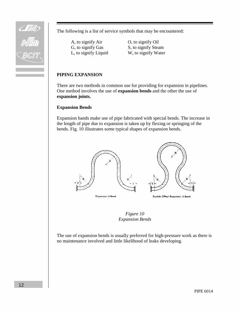
PIPING EXPANSION There are two methods in common use for providing for expansion in pipelines. One method involves the use of expansion bends and the other the use of expansion joints. Expansion Bends Expansion bands make use of pipe fabricated with special bends. The increase in the length of pipe due to expansion is taken up by flexing or springing of the bends. Fig. 10 illustrates some typical shapes of expansion bends.
Figure 10 Expansion Bends
The use of expansion bends is usually preferred for high-pressure work as there is no maintenance involved and little likelihood of leaks developing.
PIPE 6014 13
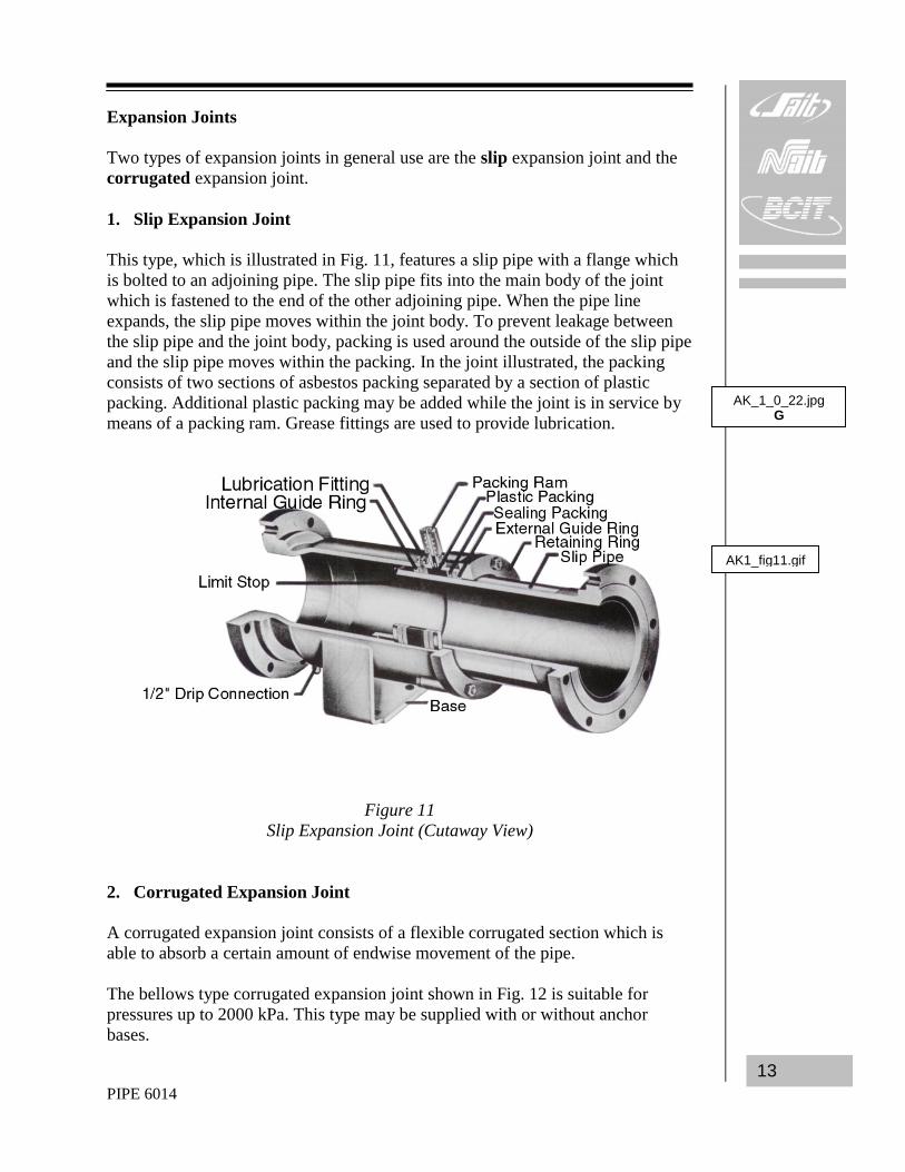
Expansion Joints Two types of expansion joints in general use are the slip expansion joint and the corrugated expansion joint. 1. Slip Expansion Joint This type, which is illustrated in Fig. 11, features a slip pipe with a flange which is bolted to an adjoining pipe. The slip pipe fits into the main body of the joint which is fastened to the end of the other adjoining pipe. When the pipe line expands, the slip pipe moves within the joint body. To prevent leakage between the slip pipe and the joint body, packing is used around the outside of the slip pipe and the slip pipe moves within the packing. In the joint illustrated, the packing consists of two sections of asbestos packing separated by a section of plastic packing. Additional plastic packing may be added while the joint is in service by means of a packing ram. Grease fittings are used to provide lubrication.
Figure 11 Slip Expansion Joint (Cutaway View)
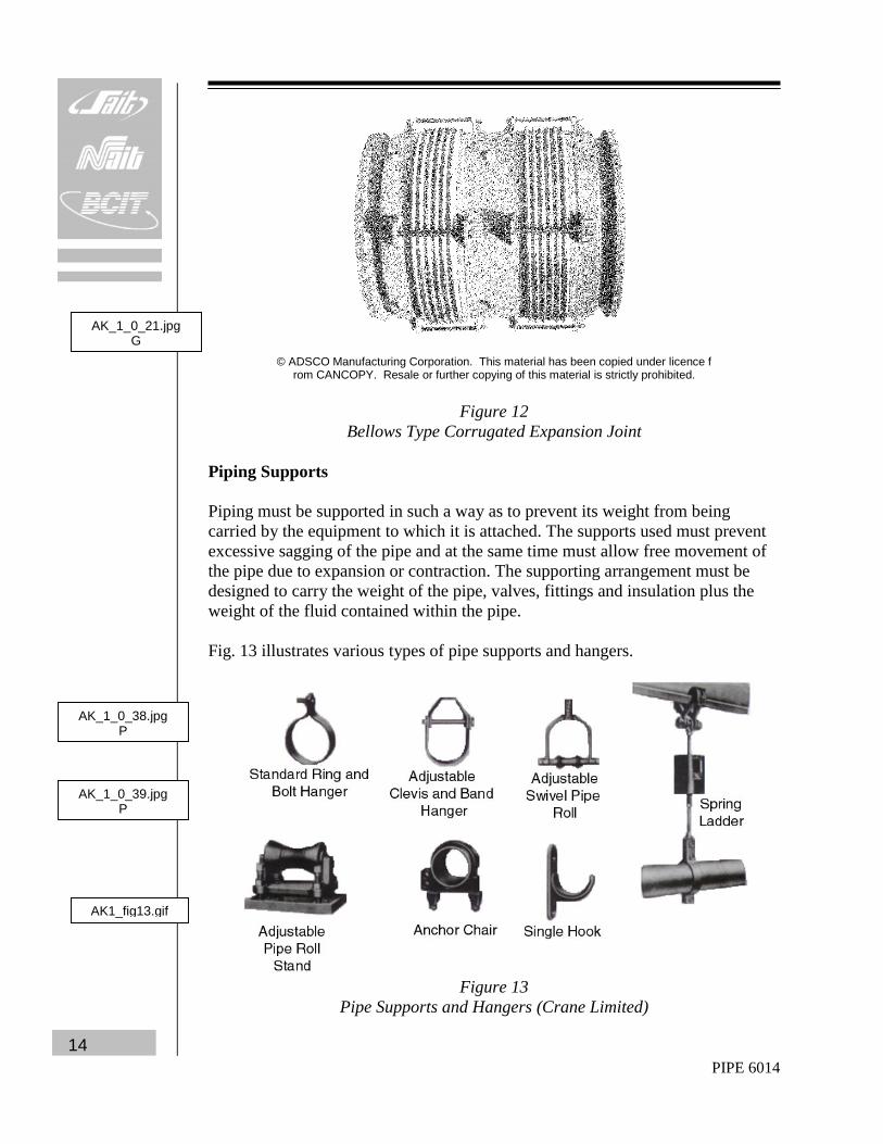
2. Corrugated Expansion Joint A corrugated expansion joint consists of a flexible corrugated section which is able to absorb a certain amount of endwise movement of the pipe. The bellows type corrugated expansion joint shown in Fig. 12 is suitable for pressures up to 2000 kPa. This type may be supplied with or without anchor bases.
Bellows Type Corrugated Expansion Joint Piping Supports Piping must be supported in such a way as to prevent its weight from being carried by the equipment to which it is attached. The supports used must prevent excessive sagging of the pipe and at the same time must allow free movement of the pipe due to expansion or contraction. The supporting arrangement must be designed to carry the weight of the pipe, valves, fittings and insulation plus the weight of the fluid contained within the pipe. Fig. 13 illustrates various types of pipe supports and hangers.
Figure 13
Pipe Supports and Hangers (Crane Limited)
AK_1_0_21.jpg G
AK_1_0_38.jpg P
AK_1_0_39.jpg P
AK1_fig13.gif
PIPE 6014 15
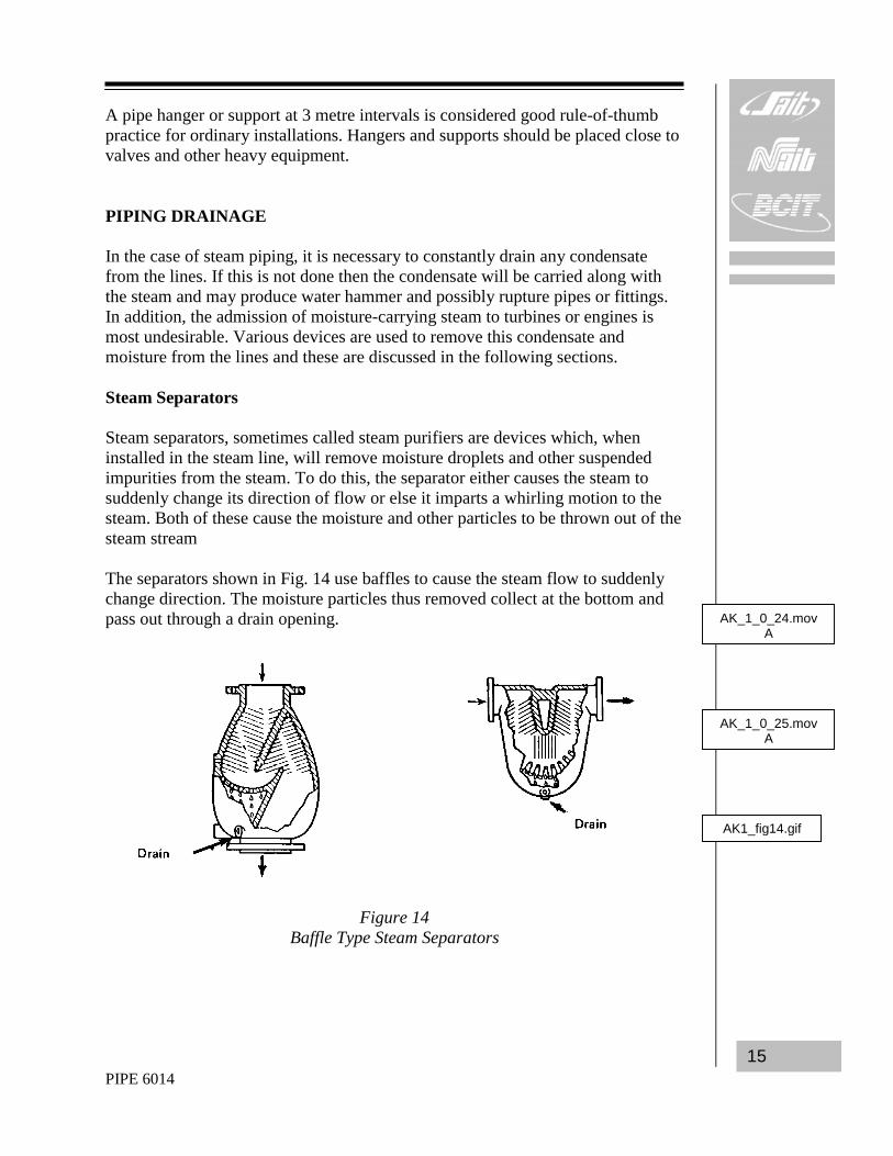
A pipe hanger or support at 3 metre intervals is considered good rule-of-thumb practice for ordinary installations. Hangers and supports should be placed close to valves and other heavy equipment. PIPING DRAINAGE In the case of steam piping, it is necessary to constantly drain any condensate from the lines. If this is not done then the condensate will be carried along with the steam and may produce water hammer and possibly rupture pipes or fittings. In addition, the admission of moisture-carrying steam to turbines or engines is most undesirable. Various devices are used to remove this condensate and moisture from the lines and these are discussed in the following sections. Steam Separators Steam separators, sometimes called steam purifiers are devices which, when installed in the steam line, will remove moisture droplets and other suspended impurities from the steam. To do this, the separator either causes the steam to suddenly change its direction of flow or else it imparts a whirling motion to the steam. Both of these cause the moisture and other particles to be thrown out of the steam stream The separators shown in Fig. 14 use baffles to cause the steam flow to suddenly change direction. The moisture particles thus removed collect at the bottom and pass out through a drain opening.
Figure 14 Baffle Type Steam Separators
AK_1_0_24.mov A
AK_1_0_25.mov A
AK1_fig14.gif
PIPE 6014 16
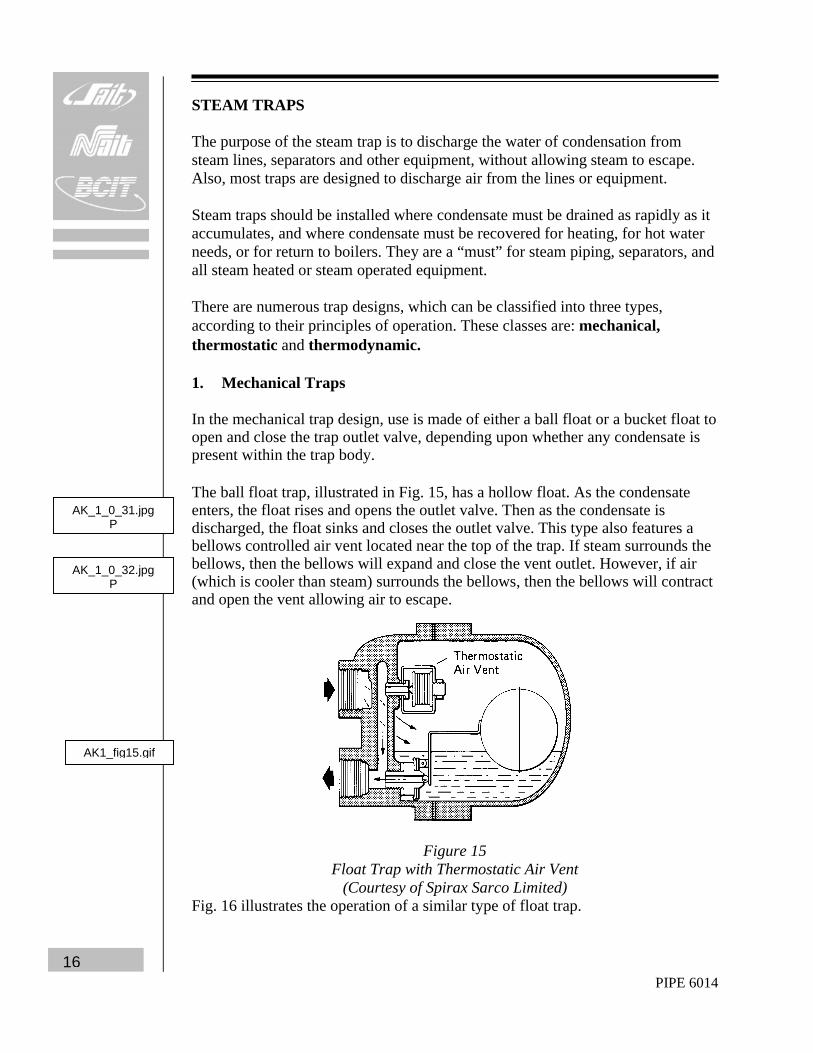
STEAM TRAPS The purpose of the steam trap is to discharge the water of condensation from steam lines, separators and other equipment, without allowing steam to escape. Also, most traps are designed to discharge air from the lines or equipment. Steam traps should be installed where condensate must be drained as rapidly as it accumulates, and where condensate must be recovered for heating, for hot water needs, or for return to boilers. They are a “must” for steam piping, separators, and all steam heated or steam operated equipment. There are numerous trap designs, which can be classified into three types, according to their principles of operation. These classes are: mechanical, thermostatic and thermodynamic. 1. Mechanical Traps In the mechanical trap design, use is made of either a ball float or a bucket float to open and close the trap outlet valve, depending upon whether any condensate is present within the trap body. The ball float trap, illustrated in Fig. 15, has a hollow float. As the condensate enters, the float rises and opens the outlet valve. Then as the condensate is discharged, the float sinks and closes the outlet valve. This type also features a bellows controlled air vent located near the top of the trap. If steam surrounds the bellows, then the bellows will expand and close the vent outlet. However, if air (which is cooler than steam) surrounds the bellows, then the bellows will contract and open the vent allowing air to escape.
Figure 15
Float Trap with Thermostatic Air Vent (Courtesy of Spirax Sarco Limited)
Fig. 16 illustrates the operation of a similar type of float trap.
AK_1_0_31.jpg P
AK_1_0_32.jpg P
AK1_fig15.gif
PIPE 6014 17
Figure 16
Float Trap Operation (Courtesy of Armstrong Machine Works)
The float trap will work equally well whether the condensate load is light or heavy; its operation is not affected by changes in steam pressure. It does not become air-locked upon start-up when there is a large amount of air present because it will discharge this air immediately and automatically. The ball float trap, however, does have the disadvantage of being vulnerable to damage from water hammer. In addition, this type of trap is not suited for outdoor use because it will freeze in cold weather. Another common mechanical trap is the inverted bucket trap. Also called an inverted open-float trap, two styles are shown in Fig. 17.
Figure 17
Inverted Bucket Trap (Courtesy of Spirax Sarco Limited)
AK_1_0_41.mov V
AK_1_0_26.jpg G
AK_1_0_27.jpg G
AK_1_0_28.jpg P
AK_1_0_36.jpg P
AK1_fig17.gif
PIPE 6014 18
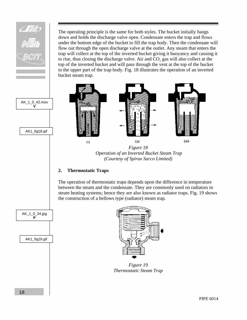
The operating principle is the same for both styles. The bucket initially hangs down and holds the discharge valve open. Condensate enters the trap and flows under the bottom edge of the bucket to fill the trap body. Then the condensate will flow out through the open discharge valve at the outlet. Any steam that enters the trap will collect at the top of the inverted bucket giving it buoyancy and causing it to rise, thus closing the discharge valve. Air and CO2 gas will also collect at the top of the inverted bucket and will pass through the vent at the top of the bucket to the upper part of the trap body. Fig. 18 illustrates the operation of an inverted bucket steam trap.
Figure 18
Operation of an Inverted Bucket Steam Trap (Courtesy of Spirax Sarco Limited)
2. Thermostatic Traps The operation of thermostatic traps depends upon the difference in temperature between the steam and the condensate. They are commonly used on radiators in steam heating systems; hence they are also known as radiator traps. Fig. 19 shows the construction of a bellows type (radiator) steam trap.
Figure 19
Thermostatic Steam Trap
AK_1_0_42.mov V
AK_1_0_34.jpg P
AK1_fig18.gif
AK1_fig19.gif
PIPE 6014 19
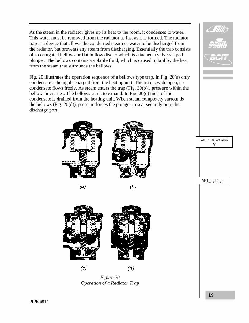
As the steam in the radiator gives up its heat to the room, it condenses to water. This water must be removed from the radiator as fast as it is formed. The radiator trap is a device that allows the condensed steam or water to be discharged from the radiator, but prevents any steam from discharging. Essentially the trap consists of a corrugated bellows or flat hollow disc to which is attached a valve-shaped plunger. The bellows contains a volatile fluid, which is caused to boil by the heat from the steam that surrounds the bellows. Fig. 20 illustrates the operation sequence of a bellows type trap. In Fig. 20(a) only condensate is being discharged from the heating unit. The trap is wide open, so condensate flows freely. As steam enters the trap (Fig. 20(b)), pressure within the bellows increases. The bellows starts to expand. In Fig. 20(c) most of the condensate is drained from the heating unit. When steam completely surrounds the bellows (Fig. 20(d)), pressure forces the plunger to seat securely onto the discharge port.
Figure 20
Operation of a Radiator Trap
AK_1_0_43.mov V
AK1_fig20.gif
PIPE 6014 20
Another type of thermostatic trap is the bimetal steam trap shown in Fig. 21.
Figure 21
Bimetal Steam Trap in the Open Position (Courtesy of Spirax Sarco Limited)
This design consists of bimetal strips (dissimilar metals, welded together), which deflect when heated. As the condensate passes through the trap its temperature will increase, deflecting the bimetal strip so that the valve opens and allows the condensate to flow through the trap. However, when the trap fills with steam the bimetal strip will deflect downwards, enough to fully close the valve. 3. Thermodynamic Traps This type of trap employs the heat energy in the steam and condensate to control its operation. One design of thermodynamic trap is the impulse trap, shown in Fig. 22.
Figure 22
Impulse Trap
AK_1_0_33.jpg P
PIPE 6014 21
This design consists of a piston type valve working within a control cylinder. When cool condensate enters the trap, the pressure of the condensate acting upon the piston disk will lift the valve to the open position thus allowing the condensate to escape through the outlet orifice. A portion of the condensate, however, instead of escaping through the outlet orifice, passes up past the piston disk into the upper part of the control cylinder and then down through a small hole drilled through the center of the piston valve to the outlet. If the condensate entering the trap is at steam temperature then the part entering the upper section of the control cylinder will flash into steam as the section is at a lower pressure (outlet pressure). The large volume of steam resulting will plug or choke the small hole through the center of the valve and pressure will build up above the piston disc thus forcing the valve into the shut position. Fig. 23 is a cutaway view of the impulse trap.
Figure 23
Impulse Trap Cutaway View (Yarnall Waring Co.)
AK1_fig23.gif
PIPE 6014 22
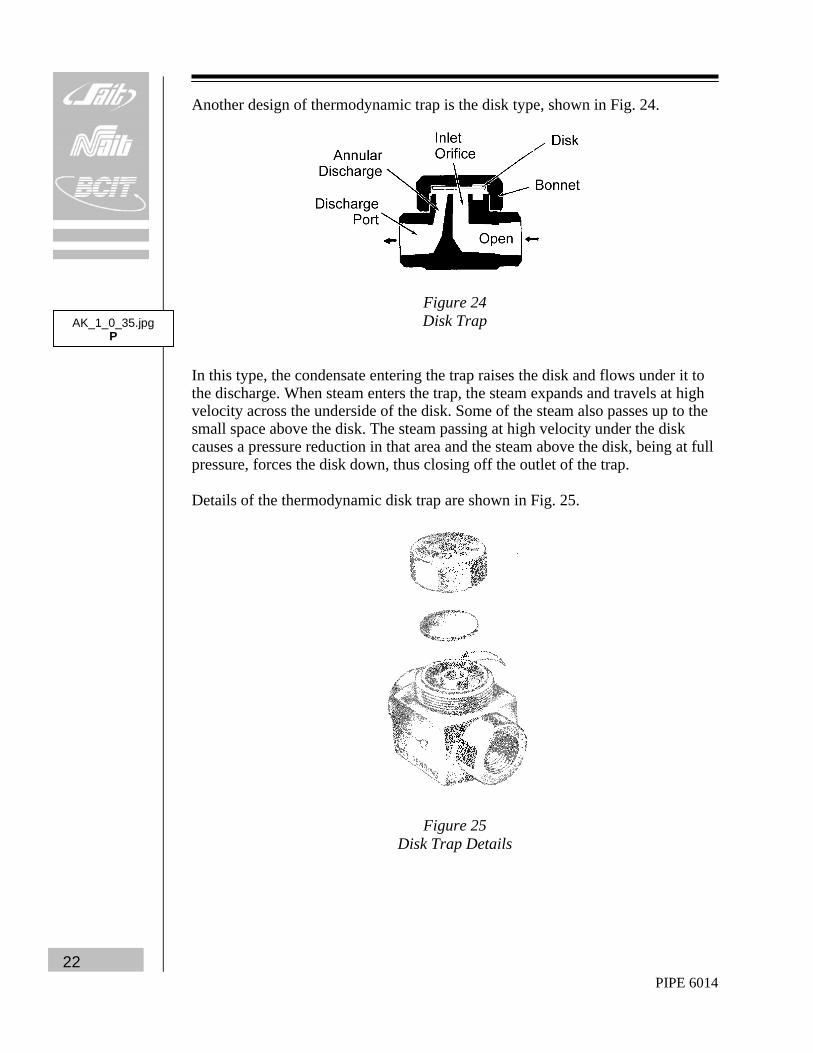
Another design of thermodynamic trap is the disk type, shown in Fig. 24.
Figure 24 Disk Trap
In this type, the condensate entering the trap raises the disk and flows under it to the discharge. When steam enters the trap, the steam expands and travels at high velocity across the underside of the disk. Some of the steam also passes up to the small space above the disk. The steam passing at high velocity under the disk causes a pressure reduction in that area and the steam above the disk, being at full pressure, forces the disk down, thus closing off the outlet of the trap. Details of the thermodynamic disk trap are shown in Fig. 25.
Figure 25 Disk Trap Details
AK_1_0_35.jpg P
PIPE 6014 23
1. Trap Installation First, blow new lines clear of all foreign matter before installing the trap. Install the trap below the lowest point in the system with the line leading to the trap pitched downward to assure good drainage. Always install a sediment separator just ahead of the trap to prevent the entry of foreign matter. Inlet and outlet gate valves permit isolating the trap for inspection and cleaning. A bypass line with a globe valve makes it possible to rid the system of condensate by hand throttling while the trap is out of service. Fig. 26 shows the piping arrangement.
Figure 26 Typical Piping Arrangement for Inverted Open Float Steam Trap
(Crane Limited) To put the trap into operation, close the gate valve in the outlet line, open the inlet gate valve, and allow condensate to fill the trap. When the trap is filled, open the outlet gate valve. 3. Trap Inspection and Servicing Frequency of inspection depends on condition of the line. To isolate the trap for inspection, close the inlet and outlet gate valves and open the sediment blow-off or the test valve to relieve the pressure. Inspection or repairs can be made while the trap is in the line or the trap can be removed from the line easily by loosening the unions.
AK_1_0_30.jpg P
AK_1_0_37.jpg P
AK_1_0_49.mov V
AK_1_0_47.mov V
PIPE 6014 24
WATER HAMMER Water hammer is the term used to describe a series of shocks produced by a sudden change in velocity of water flowing within a pipeline. This sudden change of velocity may be caused by the rapid closing or opening of a valve or by the rapid condensation of a pocket of steam within the pipe. Another situation that produce water hammer is the sudden stopping of a motor driven centrifugal pump due to a power interruption or “trip out”. When this happens, the water in the pump discharge line will stop and then reverse direction. Subsequent rapid closing of the check valve at the pump will cause water hammer. Water hammer will also be produced if steam is admitted to a pipe containing water or condensate. The steam on passing through, above the surface of the water, will raise up behind it a mass of water and thus a pocket of steam will be formed. This steam will rapidly condense due to contact with the water and a vacuum will be formed in the pocket. The water rushing into this vacuum will produce water hammer, which can rupture piping or fittings. It must be stressed therefore, that before admitting steam to any piping system, all water or condensate must be positively removed from all parts of the system. Traps which are fitted to main lines, branch lines, and separators for drainage purposes must be installed with bypass lines around them which may be opened to ensure positive drainage, as shown in Fig. 26. PIPING INSULATION Most power plant piping systems are used to convey substances that are at temperatures much higher than that of the surrounding air. Examples would include the main steam piping and feedwater piping. In order to reduce the amount of heat lost to the surrounding air from the hot substance, the piping is covered with insulation. The insulation not only retains the heat in the hot lines but also prevents the temperature inside the power plant building from becoming uncomfortably high. In addition, insulation of hot pipe lines will prevent injury to personnel due to contact with the bare surfaces of the pipe. In the case of piping that carries substances at a lower temperature than that of the surrounding air, insulating the piping will prevent sweating of the pipe and consequent dripping and corrosion.
AK_1_0_23.gif G
PIPE 6014 25
A material that is suitable for use as an insulation should have the following characteristics.
1. High insulating value. 2. Long life. 3. Vermin proof. 4. Non corrosive. 5. Ability to retain its shape and insulating value when wet. 6. Ease of application and installation.
An insulating material may be defined as one that transmits heat poorly. It has been found that substances having a large number of microscopic air pockets dispersed throughout the material make the most efficient insulators. This is because the extremely small air spaces restrict the formation of convection currents and the air itself is a poor conductor of heat. Some of the more common materials used for piping insulating are discussed in the following sections. Diatomaceous Silica This material is bonded with clay and asbestos and is used for temperatures up to 1030°C. Asbestos Pipe covering sections are molded from asbestos fibre and are used for temperatures up to 650°C. Calcium Silicate This insulation is made from silica and lime and is suitable for temperatures up to 650°C. Cellular Glass This material is glass which has been melted and foamed and then molded into pipe covering forms. It can be used for temperatures up to 430°C. Magnesia (85%) This material is composed of magnesium carbonate with asbestos fibre. It is available in molded form for pipe covering and also is supplied in powdered form to be mixed with water to form an insulating cement which is used to cover pipe fittings. Magnesia pipe covering is suitable for service up to 315°C.
PIPE 6014 26
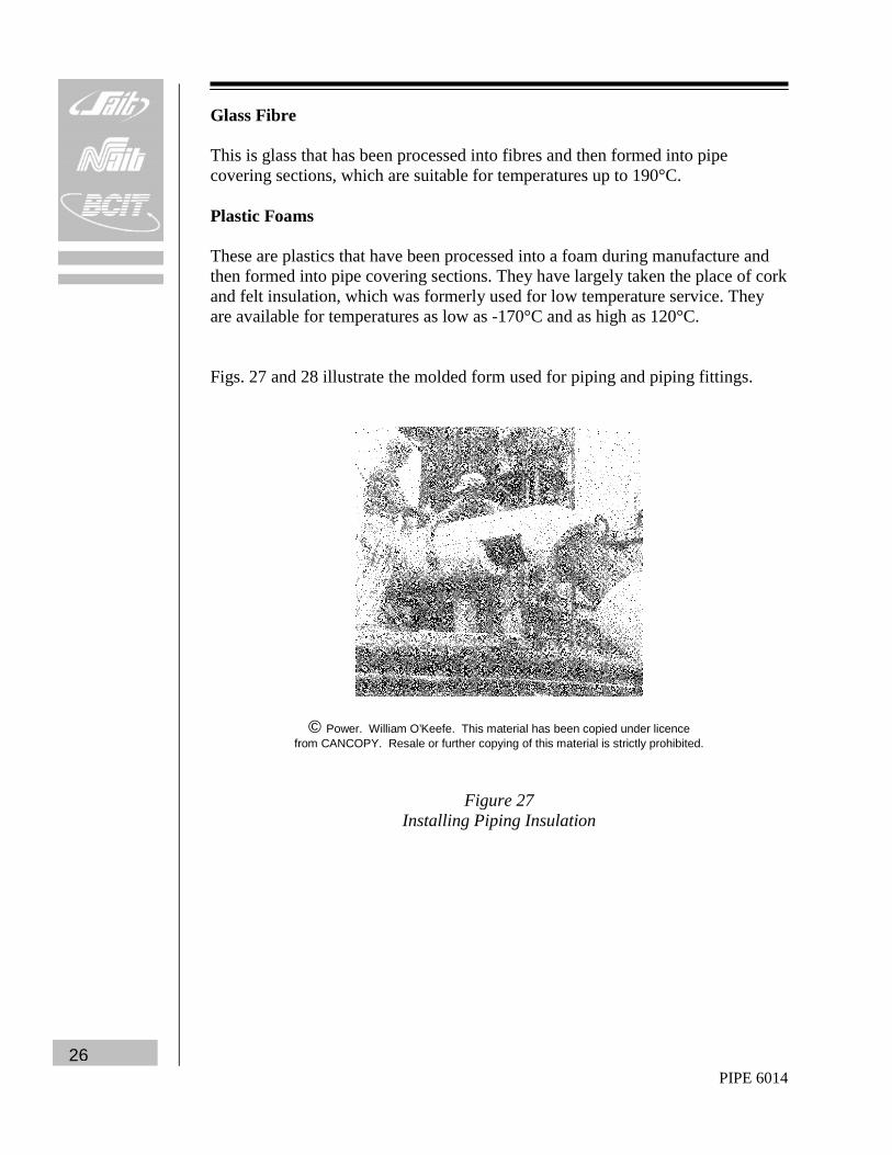
Glass Fibre This is glass that has been processed into fibres and then formed into pipe covering sections, which are suitable for temperatures up to 190°C. Plastic Foams These are plastics that have been processed into a foam during manufacture and then formed into pipe covering sections. They have largely taken the place of cork and felt insulation, which was formerly used for low temperature service. They are available for temperatures as low as -170°C and as high as 120°C. Figs. 27 and 28 illustrate the molded form used for piping and piping fittings.