Introduction to VMware vSphere ESX 4.1 ESXi 4.1 vCenter Server 4.1 This document supports the version of each product listed and supports all subsequent versions until the document is replaced by a new edition. To check for more recent editions of this document, see http://www.vmware.com/support/pubs. EN-000284-00
Transcript
Introduction to VMware vSphereESX 4.1
ESXi 4.1vCenter Server 4.1
This document supports the version of each product listed andsupports all subsequent versions until the document is replacedby a new edition. To check for more recent editions of thisdocument, see http://www.vmware.com/support/pubs.
VMware is a registered trademark or trademark of VMware, Inc. in the United States and/or other jurisdictions. All other marksand names mentioned herein may be trademarks of their respective companies.
VMware, Inc.3401 Hillview Ave.Palo Alto, CA 94304www.vmware.com
Introduction to VMware vSphere provides information about the features and functionality of VMware® vSphere.Introduction to VMware vSphere describes ESX, ESXi, and vCenter Server.
Intended AudienceThis information is for those who need to familiarize themselves with the components and capabilities ofVMware vSphere. This information is for experienced Windows or Linux system administrators who arefamiliar with virtual machine technology and datacenter operations.
VMware Technical Publications GlossaryVMware Technical Publications provides a glossary of terms that might be unfamiliar to you. For definitionsof terms as they are used in VMware technical documentation, go to http://www.vmware.com/support/pubs.
Document FeedbackVMware welcomes your suggestions for improving our documentation. If you have comments, send yourfeedback to:
Technical Support and Education ResourcesThe following technical support resources are available to you. To access the current version of this book andother books, go to http://www.vmware.com/support/pubs.
Online and TelephoneSupport
To use online support to submit technical support requests, view your productand contract information, and register your products, go to http://www.vmware.com/support.
Customers with appropriate support contracts should use telephone supportfor the fastest response on priority 1 issues. Go to http://www.vmware.com/support/phone_support.html.
Support Offerings Find out how VMware support offerings can help meet your business needs.Go to http://www.vmware.com/support/services.
VMware ProfessionalServices
VMware Education Services courses offer extensive hands-on labs, case studyexamples, and course materials designed to be used as on-the-job referencetools. Courses are available onsite, in the classroom, and live online. For onsitepilot programs and implementation best practices, VMware ConsultingServices provides offerings to help you assess, plan, build, and manage yourvirtual environment. To access information about education classes,certification programs, and consulting services, go to http://www.vmware.com/services.
VMware vSphere leverages the power of virtualization to transform datacenters into simplified cloudcomputing infrastructures and enables IT organizations to deliver flexible and reliable IT services. VMwarevSphere virtualizes and aggregates the underlying physical hardware resources across multiple systems andprovides pools of virtual resources to the datacenter.
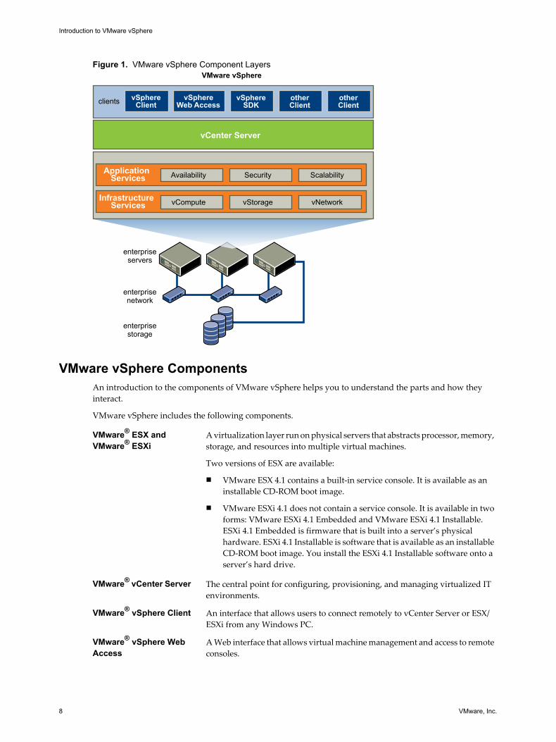
As a cloud operating system, VMware vSphere manages large collections of infrastructure (such as CPUs,storage, and networking) as a seamless and dynamic operating environment, and also manages the complexityof a datacenter. The following component layers make up VMware vSphere.
Infrastructure Services Infrastructure Services are the set of services provided to abstract, aggregate,and allocate hardware or infrastructure resources. Infrastructure Services arecategorized into several types.
n VMware vCompute, which includes the VMware capabilities that abstractaway from underlying disparate server resources. vCompute servicesaggregate these resources across many discrete servers and assign themto applications.
n VMware vStorage, which is the set of technologies that enables the mostefficient use and management of storage in virtual environments.
n VMware vNetwork, which is the set of technologies that simplify andenhance networking in virtual environments.
Application Services Application Services are the set of services provided to ensure availability,security, and scalability for applications. Examples include High Availabilityand Fault Tolerance.
VMware vCenter Server VMware vCenter Server provides a single point of control of the datacenter. Itprovides essential datacenter services such as access control, performancemonitoring, and configuration.
Clients Users can access the VMware vSphere datacenter through clients such as thevSphere Client or Web Access through a Web browser.
Figure 1 shows the relationships between the component layers of VMware vSphere.
VMware vSphere ComponentsAn introduction to the components of VMware vSphere helps you to understand the parts and how theyinteract.
VMware vSphere includes the following components.
VMware® ESX andVMware® ESXi
A virtualization layer run on physical servers that abstracts processor, memory,storage, and resources into multiple virtual machines.
Two versions of ESX are available:
n VMware ESX 4.1 contains a built-in service console. It is available as aninstallable CD-ROM boot image.
n VMware ESXi 4.1 does not contain a service console. It is available in twoforms: VMware ESXi 4.1 Embedded and VMware ESXi 4.1 Installable.ESXi 4.1 Embedded is firmware that is built into a server’s physicalhardware. ESXi 4.1 Installable is software that is available as an installableCD-ROM boot image. You install the ESXi 4.1 Installable software onto aserver’s hard drive.
VMware® vCenter Server The central point for configuring, provisioning, and managing virtualized ITenvironments.
VMware® vSphere Client An interface that allows users to connect remotely to vCenter Server or ESX/ESXi from any Windows PC.
VMware® vSphere WebAccess
A Web interface that allows virtual machine management and access to remoteconsoles.
Introduction to VMware vSphere
8 VMware, Inc.
VMware® VirtualMachine File System(VMFS)
A high performance cluster file system for ESX/ESXi virtual machines.
VMware® Virtual SMP Feature that enables a single virtual machine to use multiple physicalprocessors simultaneously.
VMware® vMotion andStorage vMotion
VMware vMotion enables the live migration of running virtual machines fromone physical server to another with zero down time, continuous serviceavailability, and complete transaction integrity. Storage vMotion enables themigration of virtual machine files from one datastore to another without serviceinterruption. You can choose to place the virtual machine and all its disks in asingle location, or select separate locations for the virtual machineconfiguration file and each virtual disk. The virtual machine remains on thesame host during Storage vMotion.
Migration with vMotion lets you move a powered-on virtual machine to a newhost. Migration with vMotion allows you to move a virtual machine to a newhost without any interruption in the availability of the virtual machine.Migration with vMotion cannot be used to move virtual machines from onedatacenter to another.
Migration with Storage vMotion lets you move the virtual disks orconfiguration file of a powered-on virtual machine to a new datastore.Migration with Storage vMotion allows you to move a virtual machine'sstorage without any interruption in the availability of the virtual machine.
VMware® HighAvailability (HA)
Feature that provides high availability for virtual machines. If a server fails,affected virtual machines are restarted on other production servers that havespare capacity.
VMware® DistributedResource Scheduler(DRS)
Feature that allocates and balances computing capacity dynamically acrosscollections of hardware resources for virtual machines. This feature includesdistributed power management (DPM) capabilities that enable a datacenter tosignificantly reduce its power consumption.
VMware® vSphere SDK Feature that provides a standard interface for VMware and third-partysolutions to access the VMware vSphere.
VMware® FaultTolerance
When Fault Tolerance is enabled for a virtual machine, a secondary copy of theoriginal (or primary) virtual machine is created. All actions completed on theprimary virtual machine are also applied to the secondary virtual machine. Ifthe primary virtual machine becomes unavailable, the secondary machinebecomes active, providing continuous availability.
vNetwork DistributedSwitch (vDS)
Feature that includes a distributed virtual switch (vDS), which spans manyESX/ESXi hosts enabling significant reduction of on-going networkmaintenance activities and increasing network capacity. This allows virtualmachines to maintain consistent network configuration as they migrate acrossmultiple hosts.
VMware vSphere Introduction
VMware, Inc. 9
Host Profiles Feature that simplifies host configuration management through user-definedconfiguration policies. The host profile policies capture the blueprint of aknown, validated host configuration and use this to configure networking,storage, security, and other settings across multiple hosts. The host profilepolicies also monitor compliance to standard host configuration settings acrossthe datacenter. Host profiles reduce manual steps involved in configuring ahost and can help maintain consistency and correctness across the datacenter.
Pluggable StorageArchitecture (PSA)
A storage partner plug-in framework that enables greater array certificationflexibility and improved array-optimized performance. PSA is a multipath I/Oframework allowing storage partners to enable their array asynchronously toESX release schedules. VMware partners can deliver performance-enhancingmultipath load-balancing behaviors that are optimized for each array.
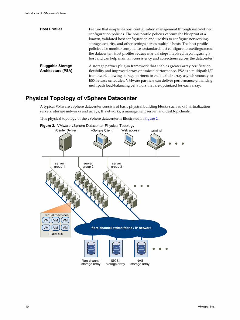
Physical Topology of vSphere DatacenterA typical VMware vSphere datacenter consists of basic physical building blocks such as x86 virtualizationservers, storage networks and arrays, IP networks, a management server, and desktop clients.
This physical topology of the vSphere datacenter is illustrated in Figure 2.
The vSphere datacenter topology includes the following components.
Computing servers Industry standard x86 servers that run ESX/ESXi on the bare metal. ESX/ESXisoftware provides resources for and runs the virtual machines. Each computingserver is referred to as a standalone host in the virtual environment. You cangroup a number of similarly configured x86 servers with connections to thesame network and storage subsystems to provide an aggregate set of resourcesin the virtual environment, called a cluster.
Storage networks andarrays
Fibre Channel SAN arrays, iSCSI SAN arrays, and NAS arrays are widely usedstorage technologies supported by VMware vSphere to meet differentdatacenter storage needs. The storage arrays are connected to and sharedbetween groups of servers through storage area networks. This arrangementallows aggregation of the storage resources and provides more flexibility inprovisioning them to virtual machines.
IP networks Each computing server can have multiple NICs to provide high bandwidth andreliable networking to the entire VMware vSphere datacenter.
vCenter Server vCenter Server provides a single point of control to the datacenter. It providesessential datacenter services such as access control, performance monitoring,and configuration. It unifies the resources from the individual computingservers to be shared among virtual machines in the entire datacenter. It doesthis by managing the assignment of virtual machines to the computing serversand the assignment of resources to the virtual machines within a givencomputing server based on the policies that the system administrator sets.
Computing servers continue to function even in the unlikely event that vCenterServer becomes unreachable (for example, if the network is severed). Serverscan be managed separately and continue to run the virtual machines assignedto them based on the resource assignment that was last set. After connectionto vCenter Server is restored, it can manage the datacenter as a whole again.
Management clients VMware vSphere provides several interfaces for datacenter management andvirtual machine access. These interfaces include VMware vSphere Client(vSphere Client), web access through a web browser, vSphere Command-LineInterface (vSphere CLI), or vSphere Management Assistant (vMA).
Virtual Datacenter ArchitectureVMware vSphere virtualizes the entire IT infrastructure including servers, storage, and networks.
VMware vSphere aggregates these resources and presents a uniform set of elements in the virtual environment.With VMware vSphere, you can manage IT resources like a shared utility and dynamically provision resourcesto different business units and projects.
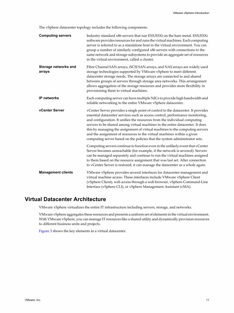
Figure 3 shows the key elements in a virtual datacenter.
VMware vSphere Introduction
VMware, Inc. 11
Figure 3. Virtual Datacenter Architecture
cluster1
host1
VM
VM
VM
VM
VM
VM
VM
RP1 RP3
RP2
datastores
network A
network B
You can use vSphere to view, configure, and manage these key elements. The following is a list of the keyelements:
n Computing and memory resources called hosts, clusters, and resource pools
n Storage resources called datastores
n Networking resources called networks
n Virtual machines
A host is the virtual representation of the computing and memory resources of a physical machine runningESX/ESXi. When two or more physical machines are grouped to work and be managed as a whole, the aggregatecomputing and memory resources form a cluster. Machines can be dynamically added or removed from acluster. Computing and memory resources from hosts and clusters can be finely partitioned into a hierarchyof resource pools.
Datastores are virtual representations of combinations of underlying physical storage resources in thedatacenter. These physical storage resources can come from the following sources:
n Local SCSI, SAS, or SATA disks of the server
n Fibre Channel SAN disk arrays
n iSCSI SAN disk arrays
n Network Attached Storage (NAS) arrays
Networks in the virtual environment connect virtual machines to one another and to the physical networkoutside of the virtual datacenter.
Virtual machines can be designated to a particular host, cluster or resource pool, and a datastore when theyare created. After they are powered-on, virtual machines consume resources dynamically as the workloadincreases or give back resources dynamically as the workload decreases.
Provisioning of virtual machines is much faster and easier than physical machines. New virtual machines canbe created in seconds. When a virtual machine is provisioned, the appropriate operating system andapplications can be installed unaltered on the virtual machine to handle a particular workload as though theywere being installed on a physical machine. A virtual machine can be provisioned with the operating systemand applications installed and configured.
Introduction to VMware vSphere
12 VMware, Inc.
Resources get provisioned to virtual machines based on the policies that are set by the system administratorwho owns the resources. The policies can reserve a set of resources for a particular virtual machine to guaranteeits performance. The policies can also prioritize and set a variable portion of the total resources to each virtualmachine. A virtual machine is prevented from being powered-on and consuming resources if doing so violatesthe resource allocation policies. For more information on resource and power management, see the ResourceManagement Guide.
Hosts, Clusters, and Resource PoolsHosts, clusters, and resources pools provide flexible and dynamic ways to organize the aggregated computingand memory resources in the virtual environment and link them back to the underlying physical resources.
A host represents the aggregate computing and memory resources of a physical x86 server. For example, if thephysical x86 server has four dual-core CPUs running at 4GHz each and 32GB of system memory, the host has32GHz of computing power and 32GB of memory available for running virtual machines that are assigned toit.
A cluster acts and can be managed as a single entity. It represents the aggregate computing and memoryresources of a group of physical x86 servers sharing the same network and storage arrays. For example, if thegroup contains eight servers with four dual-core CPUs each running at 4GHz and 32GB of memory, the clusterhas an aggregate 256GHz of computing power and 256GB of memory available for running virtual machines.
Resource pools are partitions of computing and memory resources from a single host or a cluster. Resourcepools can be hierarchical and nested. You can partition any resource pool into smaller resource pools to divideand assign resources to different groups or for different purposes.
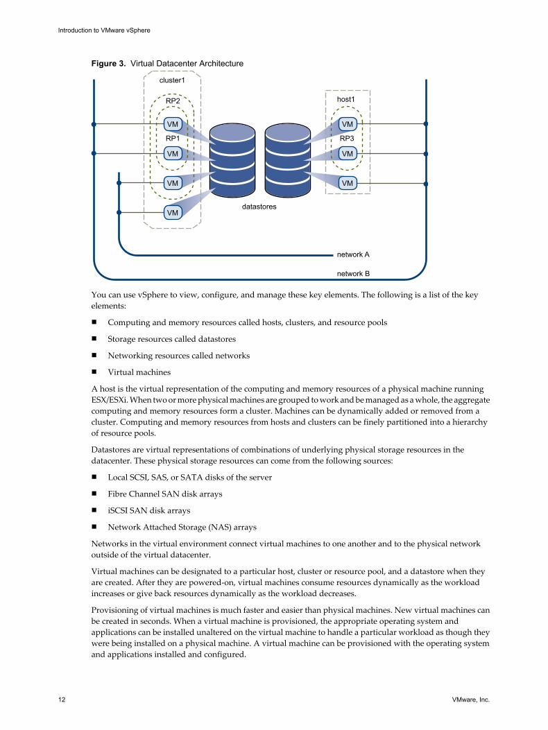
Figure 4 illustrates the use of resource pools. Three x86 servers with 4GHz computing power and 16GB ofmemory each are aggregated to form a cluster of 12GHz computing power and 48GB of memory. The FinanceDepartment resource pool reserves 8GHz of computing power and 32GB of memory from the cluster. Theremaining 4GHz computing power and 16GB of memory are reserved for the other virtual machine. From theFinance Department resource pool, the smaller Accounting resource pool reserves 4GHz computing powerand 16GB of memory for the virtual machines from the accounting department. That leaves 4GHz of computingpower and 16GB of memory for the virtual machine called Payroll.
Figure 4. Hosts, Clusters, and Resource Pools
x86 server4 GHz
16 GB RAM
Cluster12 GHz
48 GB RAM
x86 server4 GHz
16 GB RAM
x86 server4 GHz
16 GB RAM
VM VMVM VM VM
8 GHz32 GB RAM
4 GHz16 GB RAM
Finance Department
Accounting
Other Payroll
virtual
physical
VMware vSphere Introduction
VMware, Inc. 13
You can dynamically change resource allocation policies. For example, at year end, the workload onAccounting increases, and which requires an increase in the Accounting resource pool reserve of 4GHz ofpower to 6GHz. You can make the change to the resource pool dynamically without shutting down theassociated virtual machines.
When reserved resources are not being used by a resource pool or a virtual machine, the resources can beshared. In the example, if the 4GHz of resources reserved for the Accounting department are not being used,the Payroll virtual machine can use those gigahertz during its peak time. When Accounting resource demandsincrease, Payroll dynamically returns them. Resources are reserved for different resource pools, but resourcesare not wasted if an owner does not use them. This capability helps to maximize resource use while alsoensuring that reservations are met and resource policies enforced.
As demonstrated by the example, resource pools can be nested, organized hierarchically, and dynamicallyreconfigured so that the IT environment matches the company organization. Individual business units canreceive dedicated resources while still exploiting from the efficiency of resource pooling.
ESX/ESXi provides a memory compression cache to improve virtual machine performance when you usememory overcommitment. Memory compression is enabled by default. When a host's memory becomesovercommitted, ESX/ESXi compresses virtual pages and stores them in memory.
Because accessing compressed memory is faster than accessing memory that has been swapped to disk,memory compression in ESX/ESXi allows you to overcommit memory without hindering performance. Whena virtual page needs to be swapped, ESX/ESXi first attempts to compress the page. Pages that can be compressedto 2 KB or smaller are stored in the virtual machine's compression cache, increasing the capacity of the host.
VMware vSphere Distributed ServicesVMware vMotion, VMware Storage vMotion, VMware DRS, Storage I/O Control, VMware HA, and FaultTolerance are distributed services that enable efficient and automated resource management and highavailability for virtual machines.
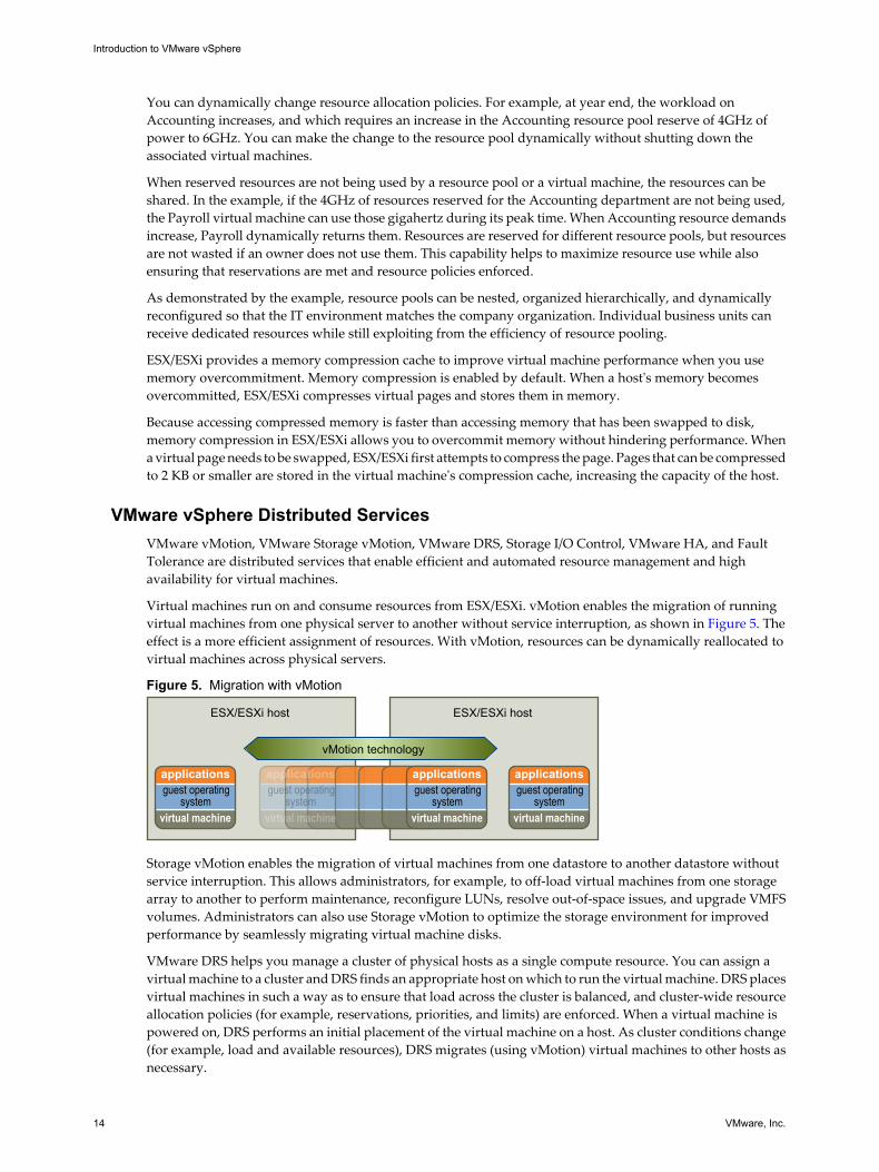
Virtual machines run on and consume resources from ESX/ESXi. vMotion enables the migration of runningvirtual machines from one physical server to another without service interruption, as shown in Figure 5. Theeffect is a more efficient assignment of resources. With vMotion, resources can be dynamically reallocated tovirtual machines across physical servers.
Figure 5. Migration with vMotion
ESX/ESXi host
vMotion technology
ESX/ESXi host
applications
virtual machine
guest operatingsystem
applications
virtual machine
guest operatingsystem
applications
virtual machine
guest operatingsystem
applications
virtual machine
guest operatingsystem
Storage vMotion enables the migration of virtual machines from one datastore to another datastore withoutservice interruption. This allows administrators, for example, to off-load virtual machines from one storagearray to another to perform maintenance, reconfigure LUNs, resolve out-of-space issues, and upgrade VMFSvolumes. Administrators can also use Storage vMotion to optimize the storage environment for improvedperformance by seamlessly migrating virtual machine disks.
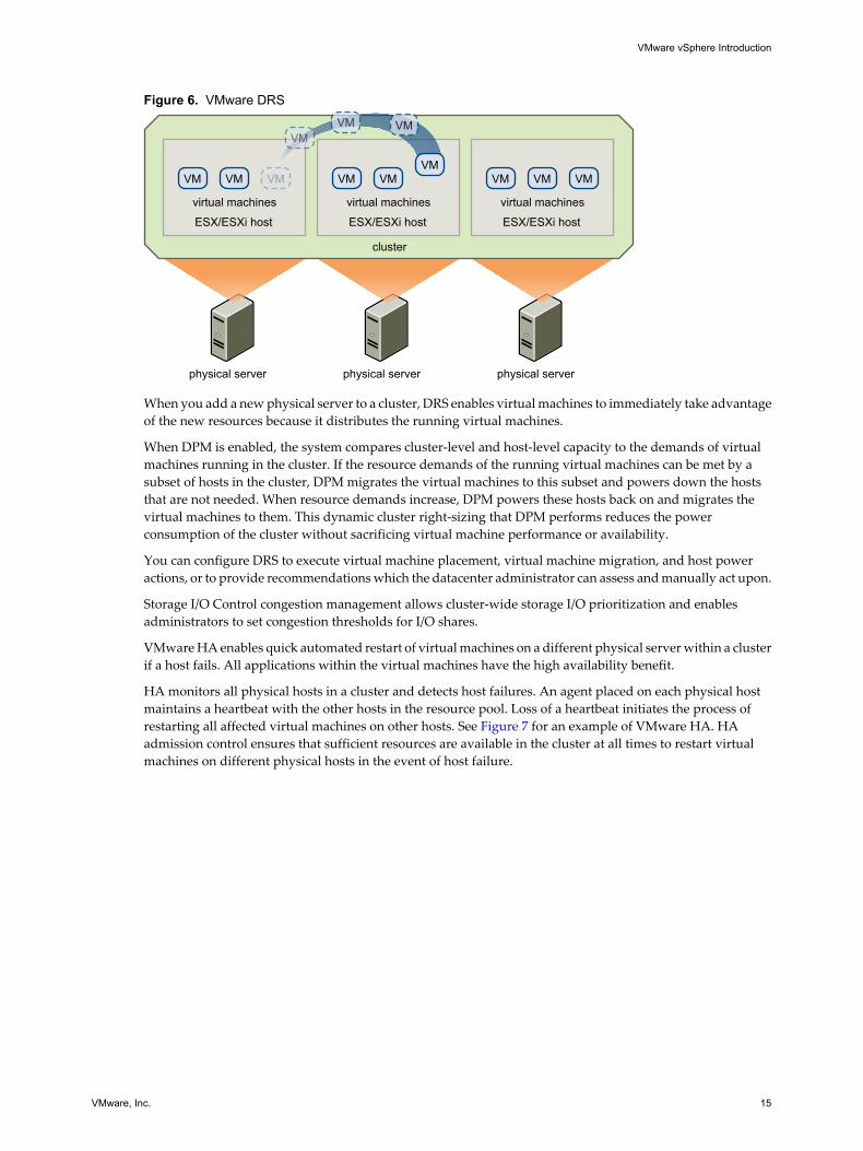
VMware DRS helps you manage a cluster of physical hosts as a single compute resource. You can assign avirtual machine to a cluster and DRS finds an appropriate host on which to run the virtual machine. DRS placesvirtual machines in such a way as to ensure that load across the cluster is balanced, and cluster-wide resourceallocation policies (for example, reservations, priorities, and limits) are enforced. When a virtual machine ispowered on, DRS performs an initial placement of the virtual machine on a host. As cluster conditions change(for example, load and available resources), DRS migrates (using vMotion) virtual machines to other hosts asnecessary.
Introduction to VMware vSphere
14 VMware, Inc.
Figure 6. VMware DRS
physical server
cluster
ESX/ESXi host
virtual machines
VM VM VM
physical server
ESX/ESXi host
virtual machines
VM VM
physical server
ESX/ESXi host
virtual machines
VM VM VM
VMVM VM
VM
When you add a new physical server to a cluster, DRS enables virtual machines to immediately take advantageof the new resources because it distributes the running virtual machines.
When DPM is enabled, the system compares cluster-level and host-level capacity to the demands of virtualmachines running in the cluster. If the resource demands of the running virtual machines can be met by asubset of hosts in the cluster, DPM migrates the virtual machines to this subset and powers down the hoststhat are not needed. When resource demands increase, DPM powers these hosts back on and migrates thevirtual machines to them. This dynamic cluster right-sizing that DPM performs reduces the powerconsumption of the cluster without sacrificing virtual machine performance or availability.
You can configure DRS to execute virtual machine placement, virtual machine migration, and host poweractions, or to provide recommendations which the datacenter administrator can assess and manually act upon.
Storage I/O Control congestion management allows cluster-wide storage I/O prioritization and enablesadministrators to set congestion thresholds for I/O shares.
VMware HA enables quick automated restart of virtual machines on a different physical server within a clusterif a host fails. All applications within the virtual machines have the high availability benefit.
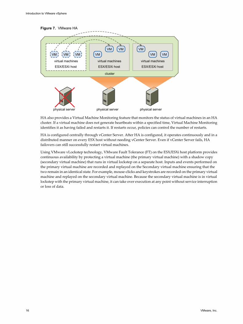
HA monitors all physical hosts in a cluster and detects host failures. An agent placed on each physical hostmaintains a heartbeat with the other hosts in the resource pool. Loss of a heartbeat initiates the process ofrestarting all affected virtual machines on other hosts. See Figure 7 for an example of VMware HA. HAadmission control ensures that sufficient resources are available in the cluster at all times to restart virtualmachines on different physical hosts in the event of host failure.
VMware vSphere Introduction
VMware, Inc. 15
Figure 7. VMware HA
physical server
cluster
ESX/ESXi host
virtual machines
VM VM VM
physical server
ESX/ESXi host
virtual machines
VMVM VM
physical server
ESX/ESXi host
virtual machines
VMVM VM
HA also provides a Virtual Machine Monitoring feature that monitors the status of virtual machines in an HAcluster. If a virtual machine does not generate heartbeats within a specified time, Virtual Machine Monitoringidentifies it as having failed and restarts it. If restarts occur, policies can control the number of restarts.
HA is configured centrally through vCenter Server. After HA is configured, it operates continuously and in adistributed manner on every ESX host without needing vCenter Server. Even if vCenter Server fails, HAfailovers can still successfully restart virtual machines.
Using VMware vLockstep technology, VMware Fault Tolerance (FT) on the ESX/ESXi host platform providescontinuous availability by protecting a virtual machine (the primary virtual machine) with a shadow copy(secondary virtual machine) that runs in virtual lockstep on a separate host. Inputs and events performed onthe primary virtual machine are recorded and replayed on the Secondary virtual machine ensuring that thetwo remain in an identical state. For example, mouse-clicks and keystrokes are recorded on the primary virtualmachine and replayed on the secondary virtual machine. Because the secondary virtual machine is in virtuallockstep with the primary virtual machine, it can take over execution at any point without service interruptionor loss of data.
Introduction to VMware vSphere
16 VMware, Inc.
Network ArchitectureVMware vSphere has a set of virtual networking elements that lets you network the virtual machines in thedatacenter like a physical environment.
Figure 8. Networking with vNetwork Standard Switches
physical network adapters
Host1
Host1
Host2
Host2
portgroups
NetworkC
VM VM VM VMVM
vSwitch
A B C D E
vSwitch
A B C D E
virtual
physical
physical network
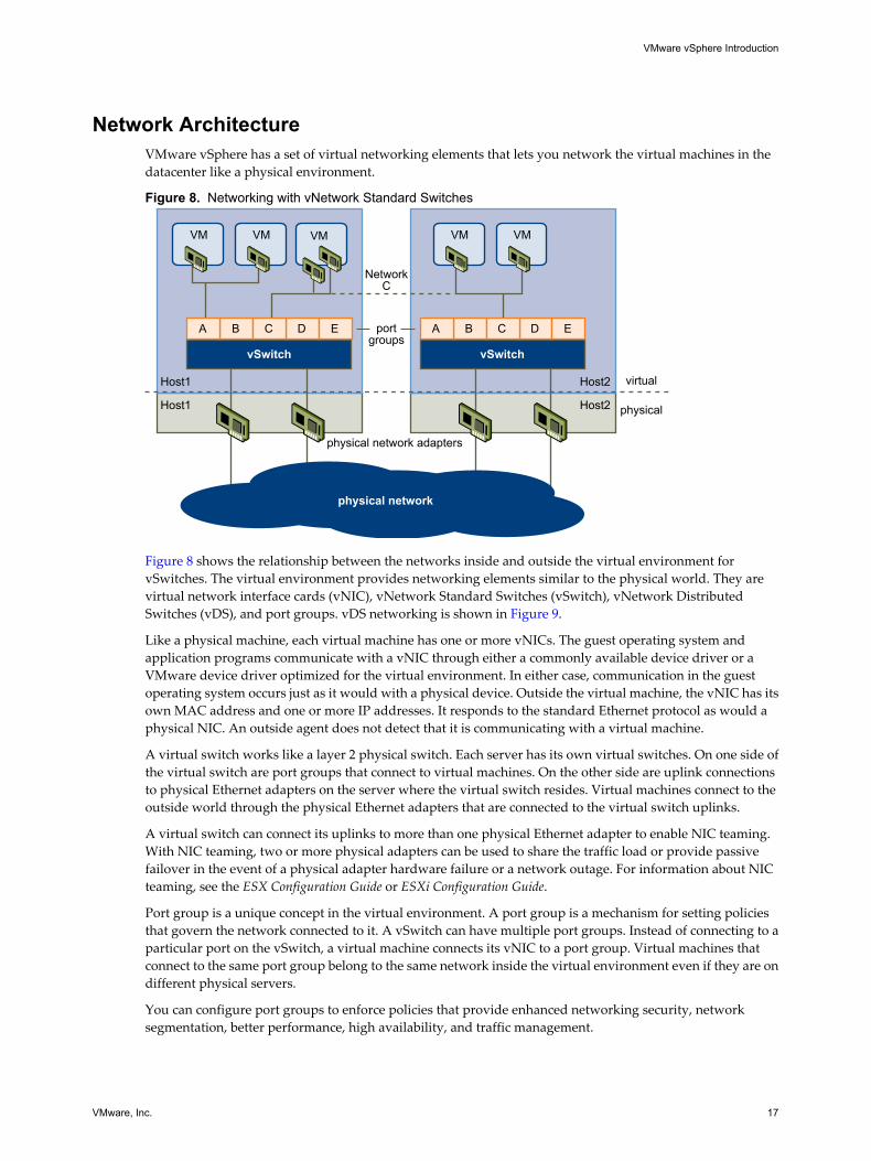
Figure 8 shows the relationship between the networks inside and outside the virtual environment forvSwitches. The virtual environment provides networking elements similar to the physical world. They arevirtual network interface cards (vNIC), vNetwork Standard Switches (vSwitch), vNetwork DistributedSwitches (vDS), and port groups. vDS networking is shown in Figure 9.
Like a physical machine, each virtual machine has one or more vNICs. The guest operating system andapplication programs communicate with a vNIC through either a commonly available device driver or aVMware device driver optimized for the virtual environment. In either case, communication in the guestoperating system occurs just as it would with a physical device. Outside the virtual machine, the vNIC has itsown MAC address and one or more IP addresses. It responds to the standard Ethernet protocol as would aphysical NIC. An outside agent does not detect that it is communicating with a virtual machine.
A virtual switch works like a layer 2 physical switch. Each server has its own virtual switches. On one side ofthe virtual switch are port groups that connect to virtual machines. On the other side are uplink connectionsto physical Ethernet adapters on the server where the virtual switch resides. Virtual machines connect to theoutside world through the physical Ethernet adapters that are connected to the virtual switch uplinks.
A virtual switch can connect its uplinks to more than one physical Ethernet adapter to enable NIC teaming.With NIC teaming, two or more physical adapters can be used to share the traffic load or provide passivefailover in the event of a physical adapter hardware failure or a network outage. For information about NICteaming, see the ESX Configuration Guide or ESXi Configuration Guide.
Port group is a unique concept in the virtual environment. A port group is a mechanism for setting policiesthat govern the network connected to it. A vSwitch can have multiple port groups. Instead of connecting to aparticular port on the vSwitch, a virtual machine connects its vNIC to a port group. Virtual machines thatconnect to the same port group belong to the same network inside the virtual environment even if they are ondifferent physical servers.
You can configure port groups to enforce policies that provide enhanced networking security, networksegmentation, better performance, high availability, and traffic management.
VMware vSphere Introduction
VMware, Inc. 17
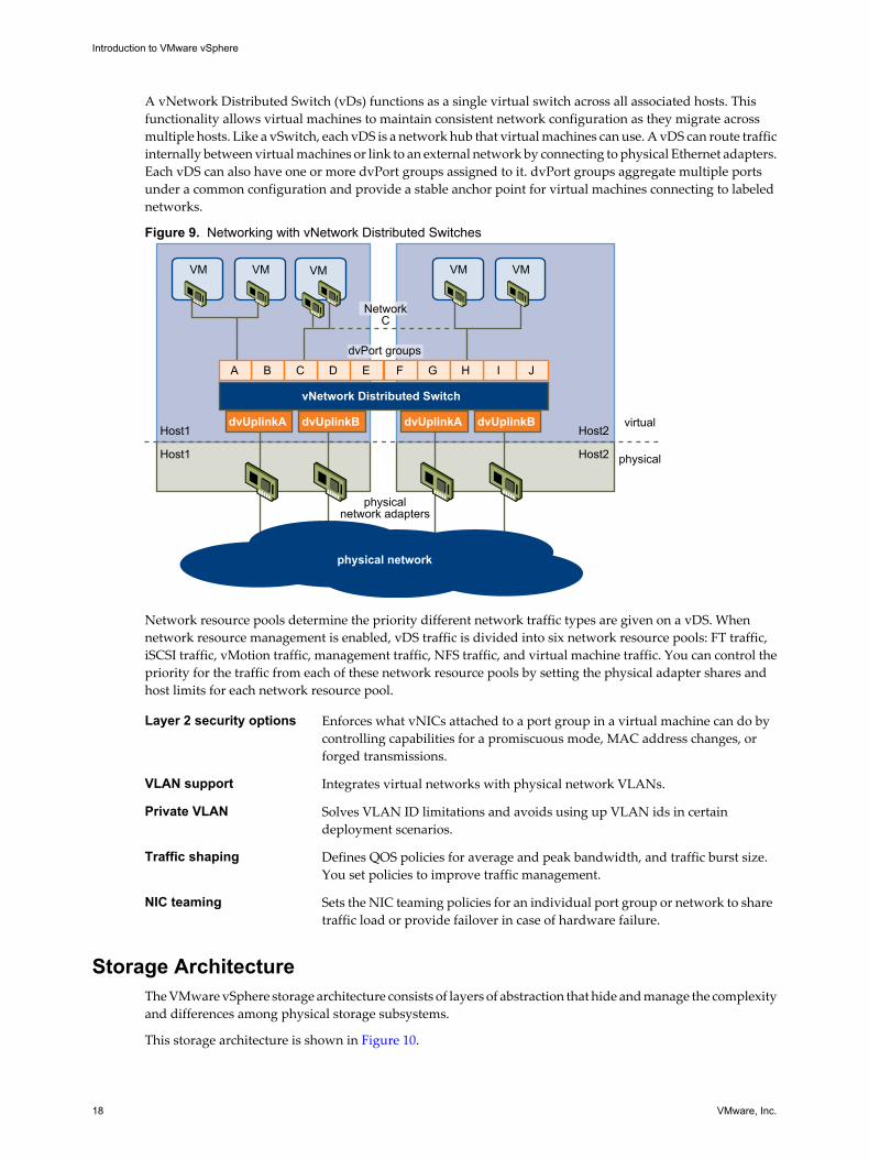
A vNetwork Distributed Switch (vDs) functions as a single virtual switch across all associated hosts. Thisfunctionality allows virtual machines to maintain consistent network configuration as they migrate acrossmultiple hosts. Like a vSwitch, each vDS is a network hub that virtual machines can use. A vDS can route trafficinternally between virtual machines or link to an external network by connecting to physical Ethernet adapters.Each vDS can also have one or more dvPort groups assigned to it. dvPort groups aggregate multiple portsunder a common configuration and provide a stable anchor point for virtual machines connecting to labelednetworks.
Figure 9. Networking with vNetwork Distributed Switches
physical network adapters
Host1
Host1
Host2
Host2
NetworkC
VM VM VM VMVM
vNetwork Distributed Switch
dvUplinkA dvUplinkB dvUplinkA dvUplinkB
A B C D E F G H I J
virtual
dvPort groups
physical
physical network
Network resource pools determine the priority different network traffic types are given on a vDS. Whennetwork resource management is enabled, vDS traffic is divided into six network resource pools: FT traffic,iSCSI traffic, vMotion traffic, management traffic, NFS traffic, and virtual machine traffic. You can control thepriority for the traffic from each of these network resource pools by setting the physical adapter shares andhost limits for each network resource pool.
Layer 2 security options Enforces what vNICs attached to a port group in a virtual machine can do bycontrolling capabilities for a promiscuous mode, MAC address changes, orforged transmissions.
VLAN support Integrates virtual networks with physical network VLANs.
Private VLAN Solves VLAN ID limitations and avoids using up VLAN ids in certaindeployment scenarios.
Traffic shaping Defines QOS policies for average and peak bandwidth, and traffic burst size.You set policies to improve traffic management.
NIC teaming Sets the NIC teaming policies for an individual port group or network to sharetraffic load or provide failover in case of hardware failure.
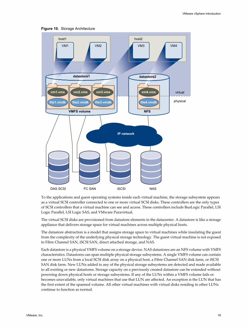
Storage ArchitectureThe VMware vSphere storage architecture consists of layers of abstraction that hide and manage the complexityand differences among physical storage subsystems.
This storage architecture is shown in Figure 10.
Introduction to VMware vSphere
18 VMware, Inc.
Figure 10. Storage Architecture
VMFS volume
DAS SCSI FC SAN iSCSI NAS
NFS
VM1 VM2 VM3 VM4
file1.vmdk
vm1.vmx
file2.vmdk
vm2.vmx
file3.vmdk
vm3.vmx
file4.vmdk
vm4.vmx
datastore1 datastore2
virtual
physical
host1 host2
IP network
To the applications and guest operating systems inside each virtual machine, the storage subsystem appearsas a virtual SCSI controller connected to one or more virtual SCSI disks. These controllers are the only typesof SCSI controllers that a virtual machine can see and access. These controllers include BusLogic Parallel, LSILogic Parallel, LSI Logic SAS, and VMware Paravirtual.
The virtual SCSI disks are provisioned from datastore elements in the datacenter. A datastore is like a storageappliance that delivers storage space for virtual machines across multiple physical hosts.
The datastore abstraction is a model that assigns storage space to virtual machines while insulating the guestfrom the complexity of the underlying physical storage technology. The guest virtual machine is not exposedto Fibre Channel SAN, iSCSI SAN, direct attached storage, and NAS.
Each datastore is a physical VMFS volume on a storage device. NAS datastores are an NFS volume with VMFScharacteristics. Datastores can span multiple physical storage subsystems. A single VMFS volume can containone or more LUNs from a local SCSI disk array on a physical host, a Fibre Channel SAN disk farm, or iSCSISAN disk farm. New LUNs added to any of the physical storage subsystems are detected and made availableto all existing or new datastores. Storage capacity on a previously created datastore can be extended withoutpowering down physical hosts or storage subsystems. If any of the LUNs within a VMFS volume fails orbecomes unavailable, only virtual machines that use that LUN are affected. An exception is the LUN that hasthe first extent of the spanned volume. All other virtual machines with virtual disks residing in other LUNscontinue to function as normal.
VMware vSphere Introduction
VMware, Inc. 19
Each virtual machine is stored as a set of files in a directory in the datastore. The disk storage associated witheach virtual guest is a set of files within the guest's directory. You can operate on the guest disk storage as anordinary file. The disk storage can be copied, moved, or backed up. New virtual disks can be added to a virtualmachine without powering it down. In that case, a virtual disk file (.vmdk) is created in VMFS to provide newstorage for the added virtual disk or an existing virtual disk file is associated with a virtual machine.
VMFS is a clustered file system that leverages shared storage to allow multiple physical hosts to read and writeto the same storage simultaneously. VMFS provides on-disk locking to ensure that the same virtual machineis not powered on by multiple servers at the same time. If a physical host fails, the on-disk lock for each virtualmachine is released so that virtual machines can be restarted on other physical hosts.
VMFS also features failure consistency and recovery mechanisms, such as distributed journaling, a failure-consistent virtual machine I/O path, and virtual machine state snapshots. These mechanisms can aid quickidentification of the cause and recovery from virtual machine, physical host, and storage subsystem failures.
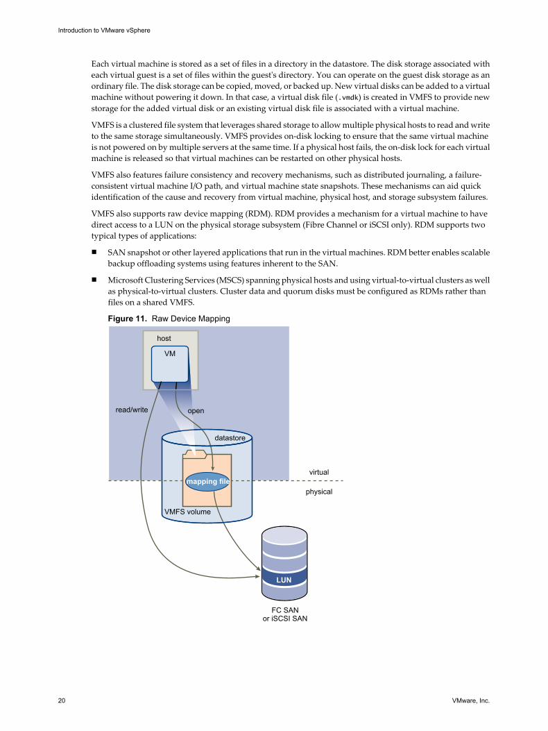
VMFS also supports raw device mapping (RDM). RDM provides a mechanism for a virtual machine to havedirect access to a LUN on the physical storage subsystem (Fibre Channel or iSCSI only). RDM supports twotypical types of applications:
n SAN snapshot or other layered applications that run in the virtual machines. RDM better enables scalablebackup offloading systems using features inherent to the SAN.
n Microsoft Clustering Services (MSCS) spanning physical hosts and using virtual-to-virtual clusters as wellas physical-to-virtual clusters. Cluster data and quorum disks must be configured as RDMs rather thanfiles on a shared VMFS.
Figure 11. Raw Device Mapping
VMFS volume
FC SANor iSCSI SAN
LUN
datastore
openread/write
virtual
physical
host
mapping file
VM
Introduction to VMware vSphere
20 VMware, Inc.
An RDM is a symbolic link from a VMFS volume to a raw LUN. The mapping makes LUNs appear as files ina VMFS volume. The mapping file, not the raw LUN, is referenced in the virtual machine configuration.
When a LUN is opened for access, the mapping file is read to obtain the reference to the raw LUN. Thereafter,reads and writes go directly to the raw LUN rather than going through the mapping file.
VMware vCenter ServerVMware vCenter Server provides centralized management for datacenters.
vCenter Server aggregates physical resources from multiple ESX/ESXi hosts and presents a central collectionof flexible resources for the system administrator to provision to virtual machines in the virtual environment.
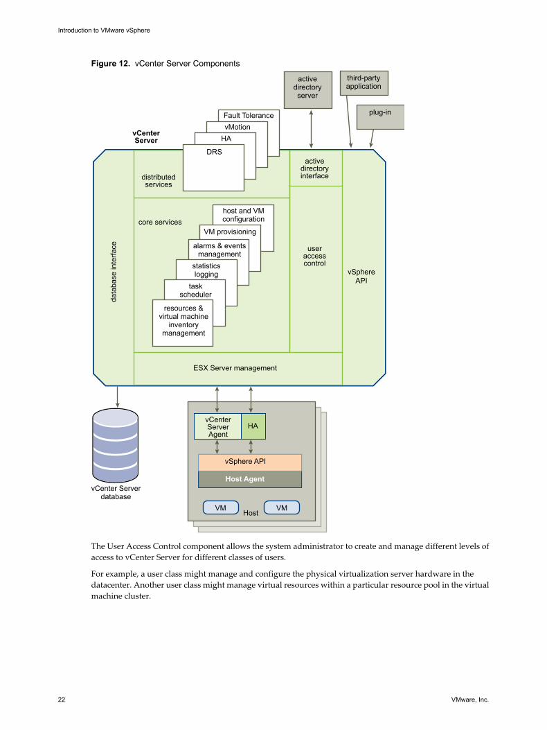
vCenter Server components are user access control, core services, distributed services, plug-ins, and variousinterfaces.
Figure 12 shows the key components of vCenter Server.
VMware vSphere Introduction
VMware, Inc. 21
Figure 12. vCenter Server Components
vMotionFault Tolerance
DRS
host and VMconfiguration
vSphereAPI
HAvCenterServer
ESX Server management
core services
distributedservices
useraccesscontrol
activedirectoryinterface
data
base
inte
rface
vCenter Serverdatabase
VM provisioning
resources &virtual machine
inventorymanagement
taskscheduler
statisticslogging
alarms & eventsmanagement
activedirectoryserver
third-partyapplication
plug-in
Host
vCenter ServerAgent
VMVM
HA
Host Agent
vSphere API
The User Access Control component allows the system administrator to create and manage different levels ofaccess to vCenter Server for different classes of users.
For example, a user class might manage and configure the physical virtualization server hardware in thedatacenter. Another user class might manage virtual resources within a particular resource pool in the virtualmachine cluster.
Introduction to VMware vSphere
22 VMware, Inc.
vCenter Server Core ServicesCore Services are basic management services for a virtual datacenter.
Core Services include the following services:
Virtual machineprovisioning
Guides and automates the provisioning of virtual machines and theirresources.
Host and VMconfiguration
Allows the configuration of hosts and virtual machines.
Resources and virtualmachine inventorymanagement
Organizes virtual machines and resources in the virtual environment andfacilitates their management.
Statistics and logging Logs and reports on the performance and resource use statistics of datacenterelements, such as virtual machines, hosts, storage, and clusters.
Alarms and eventmanagement
Tracks and warns users on potential resource overuse or event conditions. Youcan set alarms to trigger on events and notify when critical error conditionsoccur. Alarms are triggered only when they satisfy certain time conditions tominimize the number of false triggers.
Task scheduler Schedules actions such as vMotion to occur at a given time.
Consolidation Analyzes the capacity and use of a datacenter’s physical resources. Providesrecommendations for improving use by discovering physical systems that canbe converted to virtual machines and consolidated onto ESX/ESXi. Automatesthe consolidation process, but also provides the user with flexibility inadjusting consolidation parameters.
vApp A vApp has the same basic operation as a virtual machine, but can containmultiple virtual machines or appliances. With vApps, you can performoperations on multitier applications as separate entities (for example, clone,power on and off, and monitor). vApps package and manage thoseapplications.
Distributed Services are solutions that extend VMware vSphere capabilities beyond a single physical server.These solutions include: VMware DRS, VMware HA, and VMware vMotion. Distributed Services allow theconfiguration and management of these solutions centrally from vCenter Server.
Multiple vCenter Server systems can be combined into a single connected group. When a vCenter Server hostis part of a connected group, you can view and manage the inventories of all vCenter Server hosts in that group.
VMware vSphere Introduction
VMware, Inc. 23
vCenter Server Plug-InsPlug-ins are applications that you can install on top of vCenter Server. Plug-ins add additional features andfunctionality.
vCenter Server Plug-ins include the following:
VMware vCenterConverter
Enables users to convert physical machines, and virtual machines in a varietyof formats, to ESX/ESXi virtual machines. Converted systems can be importedinto any location in the vCenter Server inventory.
VMware Update Manager Enables security administrators to enforce security standards across ESX/ESXihosts and managed virtual machines. This plug-in lets you create user-definedsecurity baselines that represent a set of security standards. Securityadministrators can compare hosts and virtual machines against these baselinesto identify and remediate virtual machines that are not in compliance.
vCenter Server InterfacesvCenter Server interfaces integrate vCenter Server with third party products and applications.
vCenter Server has the following key interfaces:
ESX management Interfaces with the vCenter Server agent to manage each physical server in thedatacenter.
VMware vSphere API Interfaces with VMware management clients and third-party solutions.
Database interface Connects to Oracle, Microsoft SQL Server, or IBM DB2 to store information,such as virtual machine configurations, host configurations, resources andvirtual machine inventory, performance statistics, events, alarms, userpermissions, and roles.
Active Directoryinterface
Connects to Active Directory to obtain user access control information.
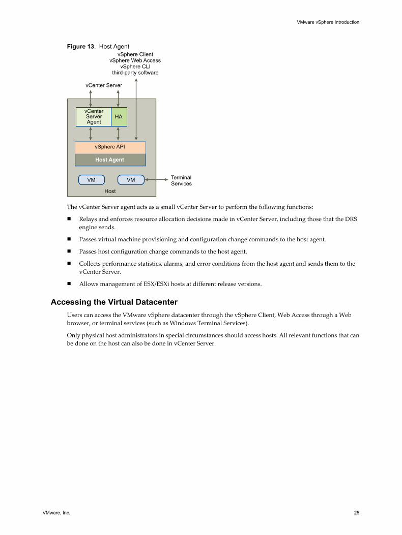
Communication Between vCenter Server and ESXvCenter Server communicates with the ESX/ESXi host agent through the VMware vSphere API.
When you first add a host to vCenter Server, vCenter Server sends a vCenter Server agent to run on the host. AsFigure 13 shows, that agent communicates with the host agent.
Introduction to VMware vSphere
24 VMware, Inc.
Figure 13. Host Agent
Host
vCenter ServerAgent
vCenter Server
TerminalServices
vSphere ClientvSphere Web Access
vSphere CLIthird-party software
VMVM
HA
Host Agent
vSphere API
The vCenter Server agent acts as a small vCenter Server to perform the following functions:
n Relays and enforces resource allocation decisions made in vCenter Server, including those that the DRSengine sends.
n Passes virtual machine provisioning and configuration change commands to the host agent.
n Passes host configuration change commands to the host agent.
n Collects performance statistics, alarms, and error conditions from the host agent and sends them to thevCenter Server.
n Allows management of ESX/ESXi hosts at different release versions.
Accessing the Virtual DatacenterUsers can access the VMware vSphere datacenter through the vSphere Client, Web Access through a Webbrowser, or terminal services (such as Windows Terminal Services).
Only physical host administrators in special circumstances should access hosts. All relevant functions that canbe done on the host can also be done in vCenter Server.
VMware vSphere Introduction
VMware, Inc. 25
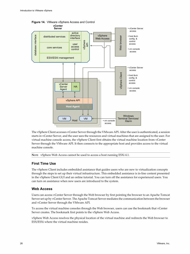
Figure 14. VMware vSphere Access and Control
Host
vSphere Web Access
vCenter ServerAgent
VMVM
HAvS
pher
e A
PI
WindowsTerminal Services/
XtermW
eb b
row
ser
vSph
ere
Clie
nt
• vCenter Server access
• host &vm config. & control access
• vm console access
• vCenter Server access
• host &vm config. & control access
• vm console access
vCenterServer
ESX/ESXi management
distributed services
core servicesuser
accesscontrol
activedirectoryinterface
data
base
inte
rface
Host Agent
vSphere API
• vm console access
The vSphere Client accesses vCenter Server through the VMware API. After the user is authenticated, a sessionstarts in vCenter Server, and the user sees the resources and virtual machines that are assigned to the user. Forvirtual machine console access, the vSphere Client first obtains the virtual machine location from vCenterServer through the VMware API. It then connects to the appropriate host and provides access to the virtualmachine console.
NOTE vSphere Web Access cannot be used to access a host running ESXi 4.1.
First Time UseThe vSphere Client includes embedded assistance that guides users who are new to virtualization conceptsthrough the steps to set up their virtual infrastructure. This embedded assistance is in-line content presentedin the vSphere Client GUI and an online tutorial. You can turn off the assistance for experienced users. Youcan turn on assistance when new users are introduced to the system.
Web AccessUsers can access vCenter Server through the Web browser by first pointing the browser to an Apache TomcatServer set up by vCenter Server. The Apache Tomcat Server mediates the communication between the browserand vCenter Server through the VMware API.
To access the virtual machine consoles through the Web browser, users can use the bookmark that vCenterServer creates. The bookmark first points to the vSphere Web Access.
vSphere Web Access resolves the physical location of the virtual machine and redirects the Web browser toESX/ESXi where the virtual machine resides.
Introduction to VMware vSphere
26 VMware, Inc.
If the virtual machine is running and the user knows the IP address of the virtual machine, the user can accessthe virtual machine console by using standard tools, such as Windows Terminal Services.
NOTE Web Access is turned off by default for ESX hosts.
Additional ResourcesYou must perform additional tasks to set up a virtual infrastructure. Each task described has references to thedocumentation that contains details about the task.
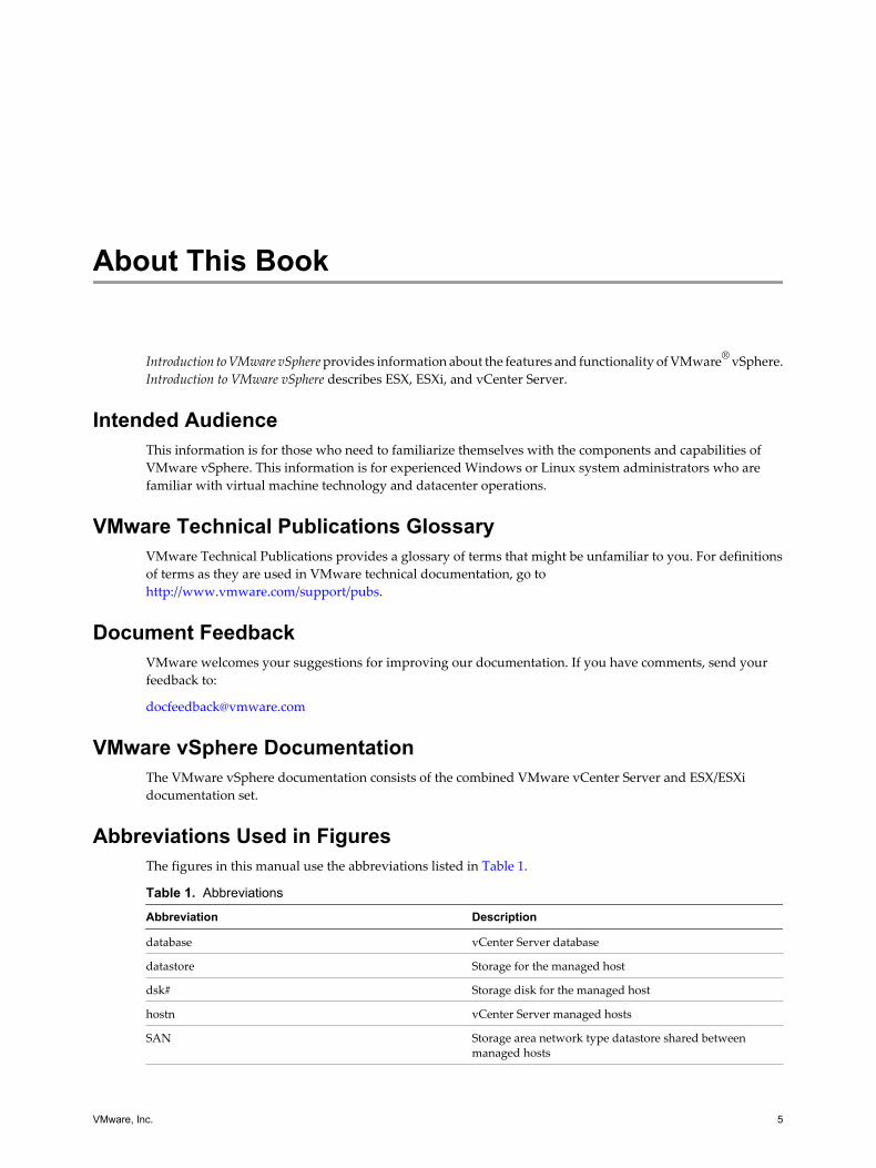
Table 2 lists the tasks and references documentation for setting up VMware vSphere. Documentation also existsfor the following topics:
n Documentation road map and quick start
n Virtual machine mobility planning
n VMware SDK and API developer resources
n Configuration maximums and release notes
Table 2. Documentation
Tasks Documents
Install vCenter Server and the vSphere Client ESX and vCenter Server Installation GuideESXi Installable and vCenter Server Setup Guide
Install ESX 4.1Install and Configure ESXi 4.1 Installable
ESX and vCenter Server Installation GuideESXi Installable and vCenter Server Setup Guide
Upgrade vCenter Server, vSphere Clients, ESX, or ESXi Upgrade Guide
Obtain and install licenses Datacenter Administration GuideESXi Installable and vCenter Server Setup Guide
Configure storage iSCSI SAN Configuration GuideFibre Channel SAN Configuration GuideESX Configuration GuideESXi Configuration Guide