Chapter 12 INTRUSION DETECTION AND EVENT MONITORING IN SCADA NETWORKS Paul Oman and Matthew Phillips Abstract This paper describes the implementation of a customized intrusion de- tection and event monitoring system for a SCADA/sensor testbed. The system raises alerts upon detecting potential unauthorized access and changes in device settings. By markedly increasing the logging of crit- ical network events, the system shows dramatic improvements in both the security and overall auditing capabilities. In addition to its role in securing SCADA networks, the system assists operators in identifying common configuration errors. Keywords: Intrusion detection, real-time monitoring, SCADA networks 1. Introduction Power system control was once a laborious process. Prior to the use of digital control equipment and communications networks, engineers had to travel to each substation to view system conditions and make changes. Technological advances enabled engineers to monitor their systems from a central location, controlling dozens of substations from a single terminal [8]. Further advances now permit engineers to control their systems – even from home – using the Internet, telephone system and wireless networks [2]. When control systems were stand-alone, devices were required to meet strict standards on operating temperatures, electrical disturbances and other envi- ronmental concerns. The operating environment has changed. In addition to meeting the harsh realities of an industrial environment, engineers must now account for new “disturbances” – electronic attacks. Process control systems are very heterogeneous environments. A power sub- station may have devices from a dozen different manufacturers. Some devices may communicate serially or via proprietary protocols on proprietary cabling, others may use Ethernet, and still others tunneling protocols over Ethernet. Some devices may be 20 years old, while others are brand new.
Transcript
Chapter 12
INTRUSION DETECTION AND EVENTMONITORING IN SCADA NETWORKS
Paul Oman and Matthew Phillips
Abstract This paper describes the implementation of a customized intrusion de-tection and event monitoring system for a SCADA/sensor testbed. Thesystem raises alerts upon detecting potential unauthorized access andchanges in device settings. By markedly increasing the logging of crit-ical network events, the system shows dramatic improvements in boththe security and overall auditing capabilities. In addition to its role insecuring SCADA networks, the system assists operators in identifyingcommon configuration errors.
Power system control was once a laborious process. Prior to the use of digitalcontrol equipment and communications networks, engineers had to travel toeach substation to view system conditions and make changes. Technologicaladvances enabled engineers to monitor their systems from a central location,controlling dozens of substations from a single terminal [8]. Further advancesnow permit engineers to control their systems – even from home – using theInternet, telephone system and wireless networks [2].
When control systems were stand-alone, devices were required to meet strictstandards on operating temperatures, electrical disturbances and other envi-ronmental concerns. The operating environment has changed. In addition tomeeting the harsh realities of an industrial environment, engineers must nowaccount for new “disturbances” – electronic attacks.
Process control systems are very heterogeneous environments. A power sub-station may have devices from a dozen different manufacturers. Some devicesmay communicate serially or via proprietary protocols on proprietary cabling,others may use Ethernet, and still others tunneling protocols over Ethernet.Some devices may be 20 years old, while others are brand new.
162 CRITICAL INFRASTRUCTURE PROTECTION
Process control systems are built to operate in high stress, time-sensitiveenvironments. The devices are simple and dedicated to performing their lim-ited tasks well. Therefore, most devices do not have the memory, processingpower and bandwidth required to perform security functions. Real-time controlsystems have several additional limitations, including:
Weak authentication mechanisms that do not differentiate between hu-man users.
No privilege separation or user account management to control access(e.g., one account, one password).
Most devices do not record login attempts (e.g., success, failure and num-ber of attempts).
Most devices cannot run user programs; they can only perform simplelogic operations.
Many users do not change the factory default settings of devices.
Many control networks are not designed with cyber security in mind.
Proprietary protocols slow the integration of security tools in control net-works.
Overall lack of monitoring and auditing (e.g., tracking changes to settingsand firmware upgrades).
Devices are notoriously difficult to set up and are typically configuredonce and left alone.
Heterogeneous control networks with components varying in age and ca-pabilities require singular attention to secure, making broad adoptionunaffordable.
These factors severely hamper efforts to secure control systems [1, 9]. For-tunately, the solutions are well-known in the information technology field [5].Indeed, many security solutions can be realized using existing technology at areasonable cost.
We have identified common security weaknesses in automated process con-trol systems, with particular attention to remotely-accessible power substa-tions [3, 4], and have created a model SCADA/sensor testbed for experimen-tation. This paper describes the implementation of a customized intrusiondetection and event monitoring system for the testbed. The system raisesalerts upon detecting potential unauthorized access and changes in device set-tings. It is useful for securing SCADA networks as well as assisting operatorsin identifying erroneous or malicious settings on SCADA devices.
Oman & Phillips 163
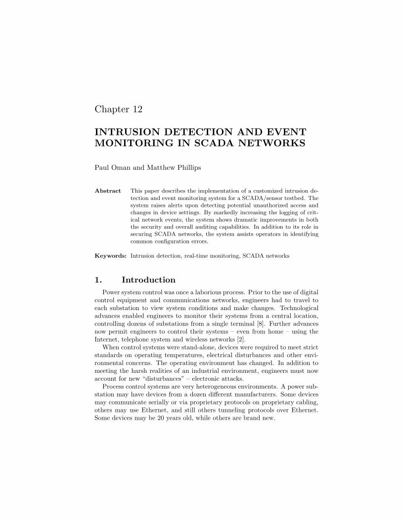
Figure 1. SCADA/sensor system testbed.
2. SCADA/Sensor System Testbed
Our SCADA/sensor system testbed was created to provide a learning andresearch environment for efforts related to SCADA security and survivability.The testbed leverages facilities at the University of Idaho’s Electrical Engineer-ing Power Laboratory, a fully functioning high-voltage facility [10, 11].
A schematic diagram of the testbed is presented in Figure 1. The testbedincorporates a communications system, sensor system, digital fault simulatorand a priority messaging system. The communication system includes a wiredEthernet network, which simulates Internet or corporate LAN traffic, and an802.11b wireless network. These networks connect a substation communica-tions processor to the SCADA master unit and other computers to enable re-mote access. The communications processor is a microprocessor-based devicethat replaces the traditional (and archaic) remote terminal unit (RTU) stillfound in many SCADA systems. It is logically programmable and serves as adata collection and communications hub with connections to the sensor systemand protective relay equipment. The wireless component of the communica-
164 CRITICAL INFRASTRUCTURE PROTECTION
tions system consists of two wireless bridges configured to communicate via apoint to multi-point topology. Protective relays are used to monitor the powersystem, control circuit breakers and report faults. The testbed incorporatesmotion and temperature sensors that raise various alarm conditions.
The power laboratory includes electrical machinery with integral horsepowermotor-generator sets ranging in size from 5 to 20 HP. A mix of AC and DCmachines permits flexible experimentation with active loads. The largest is a20 HP synchronous generator used to protect generators from internal faults.This machine, which has been modified to support development and testingschemes, is connected to the SCADA/sensor systems via power quality mea-surement equipment. Supply capability includes: 240V three phase AC at115A, 120V three phase AC at 150A, 120V at 400A DC, and 240V at 180ADC. Each supply is fed at 480V three phase AC via transformers housed in thelaboratory. DC is generated by motor-generator sets.
The laboratory also incorporates a transient network analyzer, which can beconfigured to have four transmission line segments for modeling a transmissionsystem. Full instrumentation is available for SCADA and power system pro-tection; this facilitates a wide range of experimentation related to protectingpower systems. The controls for the prime movers on the system are adjustable,allowing it to reproduce dynamic oscillations on a power grid and to demon-strate how changes in SCADA control settings can impact its behavior. Thesystem can also be used for modeling and testing custom electronic power con-trollers. Central to the ability to perform analysis of specific transient scenariosis the implementation of a computer-controlled fault generator. The fault gen-erator enables complex multiple and progressive faults to be modeled, makingreal-time voltage and current behavior during these events available for anal-ysis. The laboratory incorporates mechanical circuit breakers controlled bycommercial protective relays.
3. Research Objectives
A network intrusion detection system acts as an eavesdropping tool, listen-ing on a network for different types of traffic and payload data. Such a toolcould noticeably improve security in a SCADA network. SCADA networks alsoneed tools that remotely track changes to device configurations and settings.Monitoring network traffic and auditing network device settings provide the ba-sis for intrusion detection in IT networks; they are just as effective in SCADAnetworks [6, 10, 11].
Our research had three objectives. First, we wanted to better secure thecommunication systems of SCADA networks by monitoring for commands thatcould adversely impact the reliable operation of these networks. Second, wewanted to better monitor the settings on SCADA devices by using an auto-mated technique for gathering settings and comparing them with known (work-ing) values. Third, we wanted to use existing technologies in an extensible,cost-effective approach to improving intrusion detection and event monitoringin SCADA networks.
Oman & Phillips 165
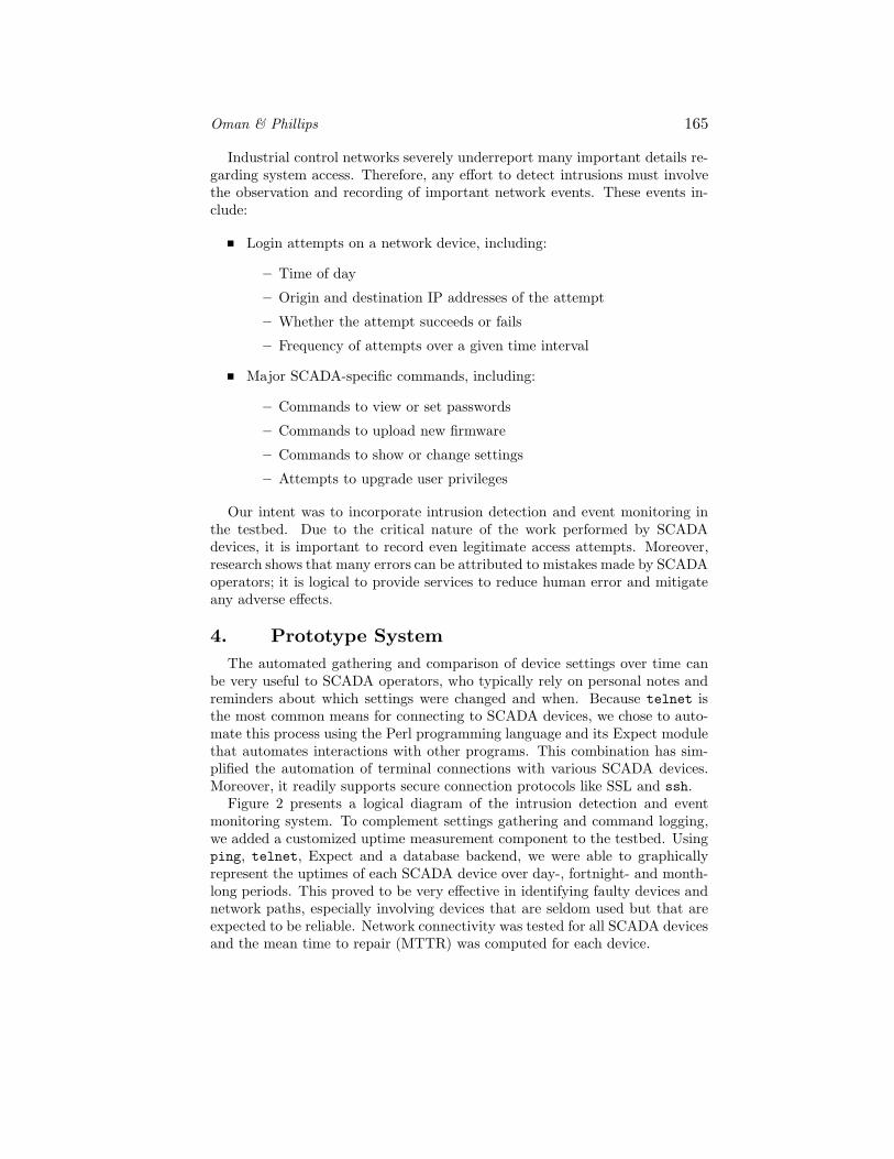
Industrial control networks severely underreport many important details re-garding system access. Therefore, any effort to detect intrusions must involvethe observation and recording of important network events. These events in-clude:
Login attempts on a network device, including:
– Time of day
– Origin and destination IP addresses of the attempt
– Whether the attempt succeeds or fails
– Frequency of attempts over a given time interval
Major SCADA-specific commands, including:
– Commands to view or set passwords
– Commands to upload new firmware
– Commands to show or change settings
– Attempts to upgrade user privileges
Our intent was to incorporate intrusion detection and event monitoring inthe testbed. Due to the critical nature of the work performed by SCADAdevices, it is important to record even legitimate access attempts. Moreover,research shows that many errors can be attributed to mistakes made by SCADAoperators; it is logical to provide services to reduce human error and mitigateany adverse effects.
4. Prototype System
The automated gathering and comparison of device settings over time canbe very useful to SCADA operators, who typically rely on personal notes andreminders about which settings were changed and when. Because telnet isthe most common means for connecting to SCADA devices, we chose to auto-mate this process using the Perl programming language and its Expect modulethat automates interactions with other programs. This combination has sim-plified the automation of terminal connections with various SCADA devices.Moreover, it readily supports secure connection protocols like SSL and ssh.
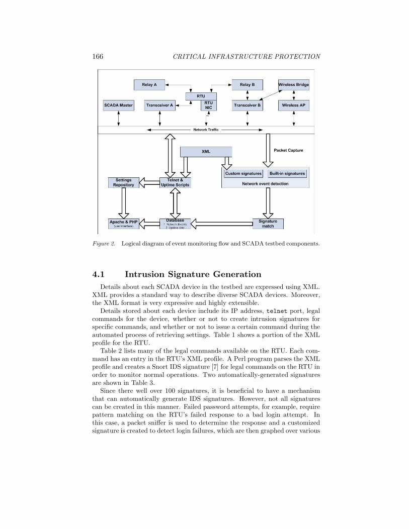
Figure 2 presents a logical diagram of the intrusion detection and eventmonitoring system. To complement settings gathering and command logging,we added a customized uptime measurement component to the testbed. Usingping, telnet, Expect and a database backend, we were able to graphicallyrepresent the uptimes of each SCADA device over day-, fortnight- and month-long periods. This proved to be very effective in identifying faulty devices andnetwork paths, especially involving devices that are seldom used but that areexpected to be reliable. Network connectivity was tested for all SCADA devicesand the mean time to repair (MTTR) was computed for each device.
166 CRITICAL INFRASTRUCTURE PROTECTION
Figure 2. Logical diagram of event monitoring flow and SCADA testbed components.
4.1 Intrusion Signature Generation
Details about each SCADA device in the testbed are expressed using XML.XML provides a standard way to describe diverse SCADA devices. Moreover,the XML format is very expressive and highly extensible.
Details stored about each device include its IP address, telnet port, legalcommands for the device, whether or not to create intrusion signatures forspecific commands, and whether or not to issue a certain command during theautomated process of retrieving settings. Table 1 shows a portion of the XMLprofile for the RTU.
Table 2 lists many of the legal commands available on the RTU. Each com-mand has an entry in the RTU’s XML profile. A Perl program parses the XMLprofile and creates a Snort IDS signature [7] for legal commands on the RTU inorder to monitor normal operations. Two automatically-generated signaturesare shown in Table 3.
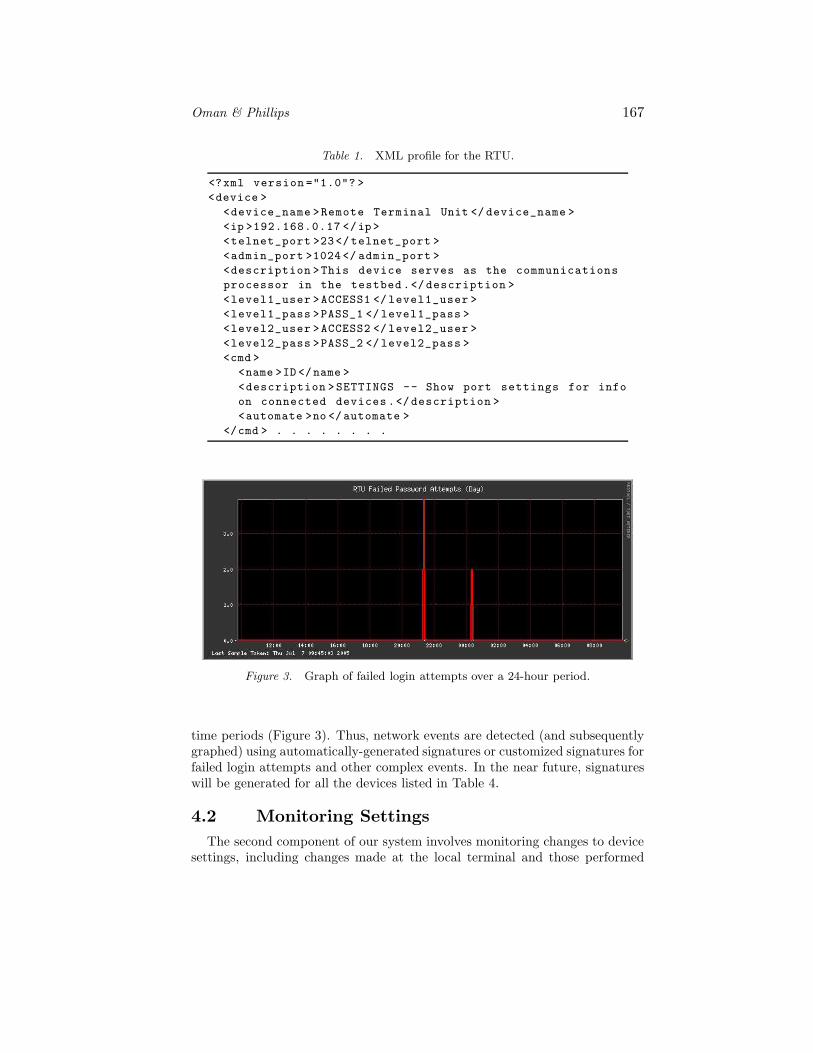
Since there well over 100 signatures, it is beneficial to have a mechanismthat can automatically generate IDS signatures. However, not all signaturescan be created in this manner. Failed password attempts, for example, requirepattern matching on the RTU’s failed response to a bad login attempt. Inthis case, a packet sniffer is used to determine the response and a customizedsignature is created to detect login failures, which are then graphed over various
<description >SETTINGS -- Show port settings for infoon connected devices .</description ><automate >no </automate >
</cmd > . . . . . . . .
Figure 3. Graph of failed login attempts over a 24-hour period.
time periods (Figure 3). Thus, network events are detected (and subsequentlygraphed) using automatically-generated signatures or customized signatures forfailed login attempts and other complex events. In the near future, signatureswill be generated for all the devices listed in Table 4.
4.2 Monitoring Settings
The second component of our system involves monitoring changes to devicesettings, including changes made at the local terminal and those performed
168 CRITICAL INFRASTRUCTURE PROTECTION
Table 2. Common commands used in the testbed.
Command Description
BROADCAST Communicate with all IEDsCLEAR Clear information from a memory areaDNP View DNP data and settingsMODBUS View MODBUS data and settingsDATE View or change the dateHELP Provide information on available commandsID Display device identification informationCLOCK Force time update using IRIG outputPORT Provide direct access to a portACCESS Change access level to Level 12ACCESS Change access level to Level 2QUIT Revert to access Level 0SETTINGS Show all device settingsSTATUS Display status and configuration informationTIME View or change the timeVIEW View information from the databaseWHO Show directly connected devicesCOPY Copy settings between portsLOAD Initiate firmware upgrade sequencePASSWORD View or change passwordsPING Ping a network deviceFTP FTP metering data from a device
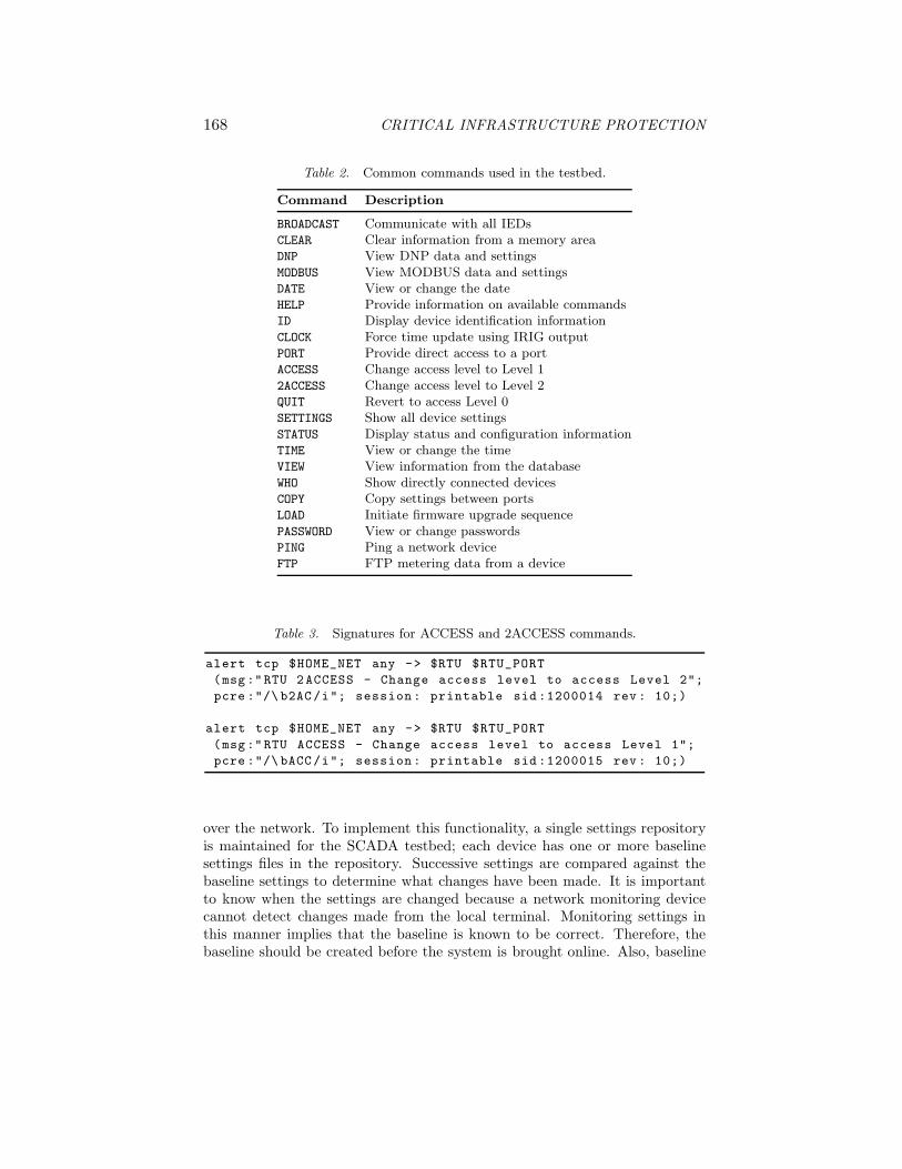
Table 3. Signatures for ACCESS and 2ACCESS commands.
alert tcp $HOME_NET any -> $RTU $RTU_PORT(msg:"RTU 2ACCESS - Change access level to access Level 2";
over the network. To implement this functionality, a single settings repositoryis maintained for the SCADA testbed; each device has one or more baselinesettings files in the repository. Successive settings are compared against thebaseline settings to determine what changes have been made. It is importantto know when the settings are changed because a network monitoring devicecannot detect changes made from the local terminal. Monitoring settings inthis manner implies that the baseline is known to be correct. Therefore, thebaseline should be created before the system is brought online. Also, baseline
Oman & Phillips 169
Table 4. Testbed devices.
Device IP Address
RTU Network Card 192.168.0.17Transceiver A 192.168.0.11Transceiver B 192.168.0.12Digital Relay A Accessible via RTUDigital Relay B Accessible via RTUWireless AP 192.168.0.227Wireless Bridge 192.168.0.225Wireless Client 192.168.0.14SCADA-MASTER 192.168.0.140Gateway 192.168.0.1
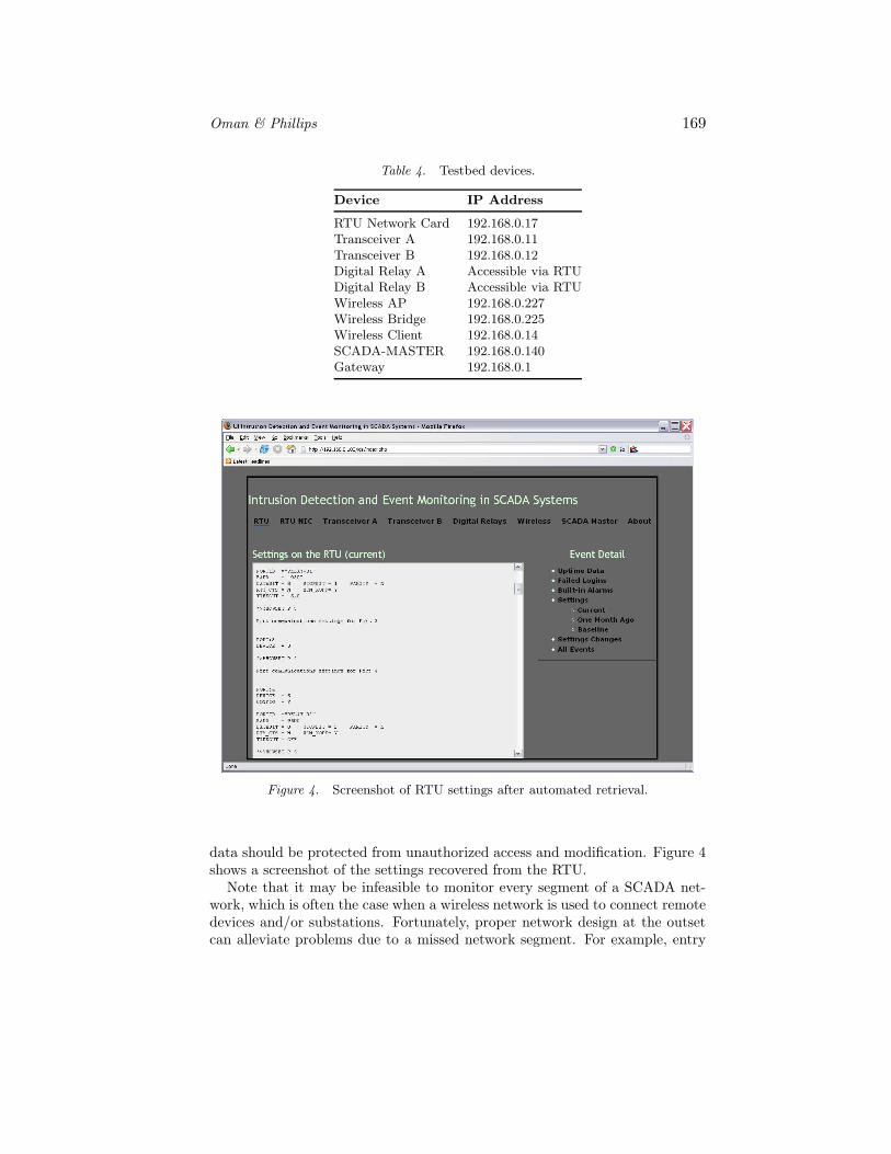
Figure 4. Screenshot of RTU settings after automated retrieval.
data should be protected from unauthorized access and modification. Figure 4shows a screenshot of the settings recovered from the RTU.
Note that it may be infeasible to monitor every segment of a SCADA net-work, which is often the case when a wireless network is used to connect remotedevices and/or substations. Fortunately, proper network design at the outsetcan alleviate problems due to a missed network segment. For example, entry
170 CRITICAL INFRASTRUCTURE PROTECTION
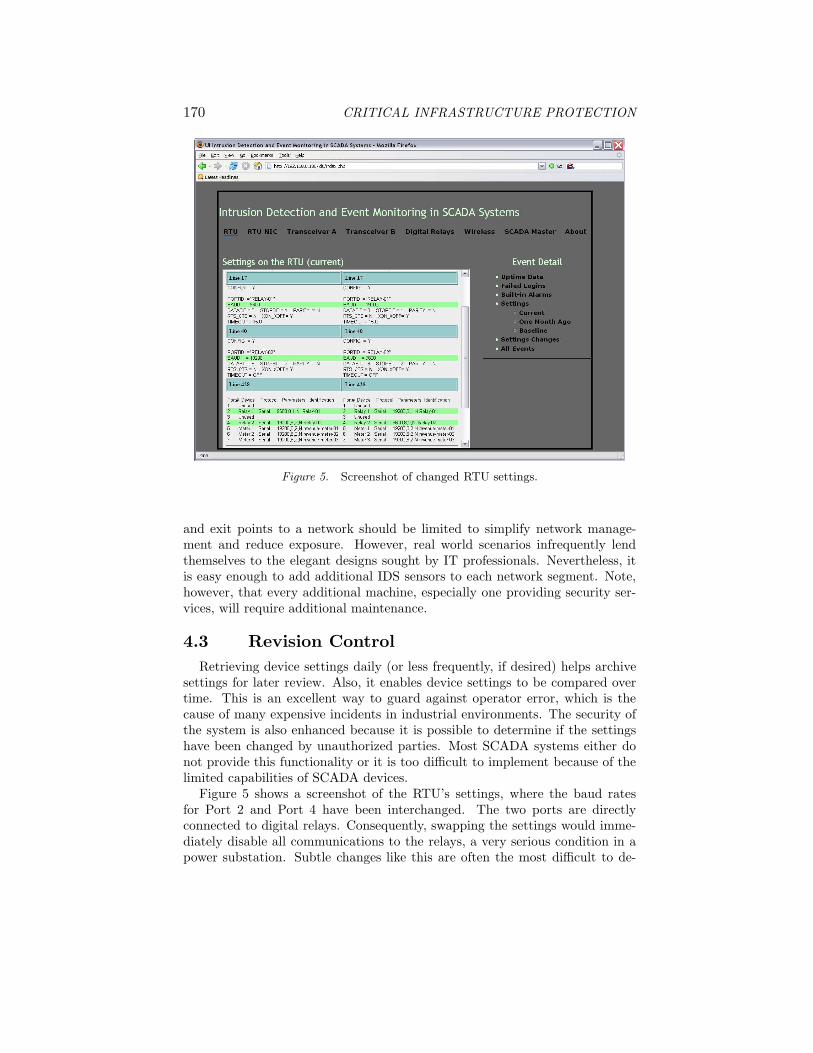
Figure 5. Screenshot of changed RTU settings.
and exit points to a network should be limited to simplify network manage-ment and reduce exposure. However, real world scenarios infrequently lendthemselves to the elegant designs sought by IT professionals. Nevertheless, itis easy enough to add additional IDS sensors to each network segment. Note,however, that every additional machine, especially one providing security ser-vices, will require additional maintenance.
4.3 Revision Control
Retrieving device settings daily (or less frequently, if desired) helps archivesettings for later review. Also, it enables device settings to be compared overtime. This is an excellent way to guard against operator error, which is thecause of many expensive incidents in industrial environments. The security ofthe system is also enhanced because it is possible to determine if the settingshave been changed by unauthorized parties. Most SCADA systems either donot provide this functionality or it is too difficult to implement because of thelimited capabilities of SCADA devices.
Figure 5 shows a screenshot of the RTU’s settings, where the baud ratesfor Port 2 and Port 4 have been interchanged. The two ports are directlyconnected to digital relays. Consequently, swapping the settings would imme-diately disable all communications to the relays, a very serious condition in apower substation. Subtle changes like this are often the most difficult to de-
Oman & Phillips 171
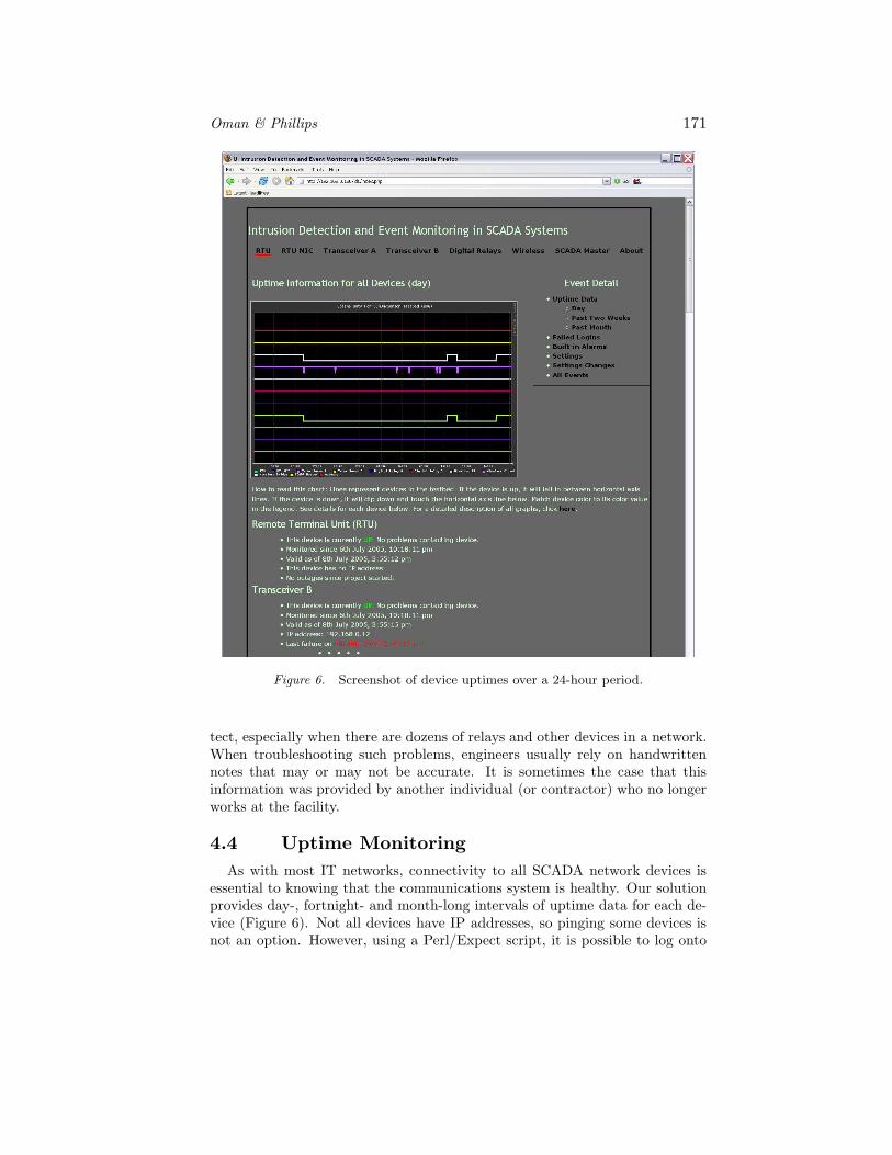
Figure 6. Screenshot of device uptimes over a 24-hour period.
tect, especially when there are dozens of relays and other devices in a network.When troubleshooting such problems, engineers usually rely on handwrittennotes that may or may not be accurate. It is sometimes the case that thisinformation was provided by another individual (or contractor) who no longerworks at the facility.
4.4 Uptime Monitoring
As with most IT networks, connectivity to all SCADA network devices isessential to knowing that the communications system is healthy. Our solutionprovides day-, fortnight- and month-long intervals of uptime data for each de-vice (Figure 6). Not all devices have IP addresses, so pinging some devices isnot an option. However, using a Perl/Expect script, it is possible to log onto
172 CRITICAL INFRASTRUCTURE PROTECTION
these devices and issue a simple command – if the command succeeds, there isverification that the path is healthy.
The script for polling devices runs every five minutes and the data gathered isstored in a database. A second script graphs the data. Such graphing providesan immediate indication when a device is unreachable; even for devices that arereachable only through others. Figure 6, for example, shows that the wirelessbridge is probably down, which results in transceiver B becoming unreachable.Mean time to repair (MTTR) can be calculated based on how long it takes onthe average to re-establish contact.
5. Conclusions
The intrusion detection and event monitoring system is useful for securingSCADA networks as well as assisting operators in identifying erroneous or ma-licious settings on SCADA devices. The automated gathering and comparisonof device settings over time is very useful to SCADA operators, who typicallyrely on personal notes and reminders about device settings.
The current prototype automates intrusion detection and settings retrievalonly for RTUs. It is currently being extended to provide this functionalityfor other SCADA devices. Special attention will be paid to retrieving settingsand detecting events involving digital relays, which are the backbone of manycritical infrastructures. Our longer term goals are to place all SCADA devicesettings under revision control and to generate signatures for unauthorizedaccess to other devices. Once this is accomplished, the system will be adaptedto vendor-specific needs and other SCADA configurations.
Acknowledgements
This research was partially supported by the National Science Foundationunder Grant DUE–0114016 (Cyber Service Training and Education) and GrantDUE–0416757 (Capacity Building for the University of Idaho Scholarship forService Program).
References
[1] Office of Energy Assurance, 21 Steps to Improve Cyber Security of SCADANetworks, U.S. Department of Energy, Washington, DC, 2002.
[2] P. Oman, A. Krings, D. Conte de Leon and J. Alves-Foss, Analyzing thesecurity and survivability of real-time control systems, Proceedings of theFifth Annual IEEE Systems, Man and Cybernetics Information AssuranceWorkshop, pp. 342–349, 2004.
[3] P. Oman, E. Schweitzer and D. Frincke, Concerns about intrusions intoremotely accessible substation controllers and SCADA systems, Proceed-ings of the Twenty-Seventh Annual Western Protective Relay Conference,2000.
Oman & Phillips 173
[4] P. Oman, E. Schweitzer and J. Roberts, Protecting the grid from cyberattack – Part 1: Recognizing our vulnerabilities, Utility Automation &Enginering T&D, vol. 6(7), pp. 16–22, 2001.
[5] P. Oman, E. Schweitzer and J. Roberts, Protecting the grid from cyberattack – Part 2: Safeguarding IEDs, substations and SCADA systems,Utility Automation & Enginering T&D, vol. 7(1), pp. 25–32, 2002.
[6] M. Phillips, Event Monitoring and Intrusion Detection in SCADA Sys-tems, M.S. Thesis, Department of Computer Science, University of Idaho,Moscow, Idaho, 2005.
[7] M. Roesch, Snort (www.snort.org).
[8] F. Sheldon, T. Potok, A. Krings and P. Oman, Critical energy infrastruc-ture survivability: Inherent limitations, obstacles and mitigation strategies,International Journal of Power and Energy Systems, pp. 86–92, 2004.
[9] U.S. House of Representatives (Committee on Government Reform),Telecommunications and SCADA: Secure links or open portals to the se-curity of our nation’s critical infrastructure, Serial No. 108–196, U.S. Gov-ernment Printing Office, Washington, DC, March 30, 2004.
[10] J. Waite, A Testbed for SCADA Security and Survivability Research andInstruction, M.S. Thesis, Department of Computer Science, University ofIdaho, Moscow, Idaho, 2004.
[11] J. Waite, J. Oman, M. Phillips, S. Melton and V. Nair, A SCADA testbedfor teaching and learning, Proceedings of the Thirty-Sixth Annual NorthAmerican Power Symposium, pp. 447–451, 2004.