Intrusion-Tolerant SCADA for the Power Grid by Thomas J. Tantillo A dissertation submitted to The Johns Hopkins University in conformity with the requirements for the degree of Doctor of Philosophy. Baltimore, Maryland September, 2018 c ⃝ Thomas J. Tantillo 2018 All rights reserved
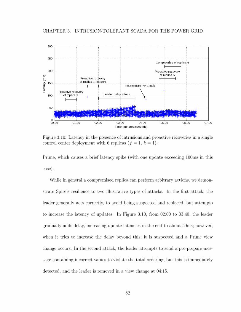
Transcript
Intrusion-Tolerant SCADA for the Power Grid
by
Thomas J. Tantillo
A dissertation submitted to The Johns Hopkins University in conformity with the
requirements for the degree of Doctor of Philosophy.
Baltimore, Maryland
September, 2018
c⃝ Thomas J. Tantillo 2018
All rights reserved
Abstract
Supervisory Control and Data Acquisition (SCADA) systems form the monitor-
ing and control backbone of the power grid. It is critical to ensure that SCADA
systems are continuously available and operating correctly at their expected level of
performance. However, as key components of the power grid infrastructure, SCADA
systems are likely to be targeted by nation-state-level attackers willing to invest con-
siderable resources to disrupt the power grid.
We present the first intrusion-tolerant SCADA system that is resilient to both
system-level compromises and sophisticated network-level attacks and compromises.
While existing SCADA systems often deploy two control centers for fault tolerance,
we show that two control centers, even if active at the same time, cannot provide the
necessary resilience. We develop a novel architecture that distributes the SCADA
system management across three or more active sites to ensure continuous availabil-
ity in the presence of simultaneous intrusions and network attacks. To make our
architecture viable for deployment by power companies that budget for no more than
two control centers, we extend our architecture to allow the two control centers used
ii
ABSTRACT
today to be augmented with one or more commodity data center sites to provide the
same level of resilience at a feasible cost.
The system design is implemented in the Spire intrusion-tolerant SCADA system,
which is available as open source. Spire was recently tested in a red-team exper-
iment, during which an experienced hacker team completely compromised a tradi-
tional SCADA system setup according to best practices, but was unable to impact
Spire’s guarantees over several days of attack. In addition, a wide-area deployment
of Spire, using two control centers and two data centers spanning 250 miles (similar
to large U.S. power grids), delivered nearly 99.999% of all SCADA updates initiated
over a 30-hour period within 100ms. These results demonstrate that Spire provides
meaningful security advantages over traditional SCADA systems and that Spire can
meet the latency requirements of SCADA for the power grid.
Advisor: Dr. Yair Amir
Readers: Dr. Yair Amir, Dr. Aviel Rubin, Dr. Marco Platania
iii
Acknowledgments
I am immensely grateful to my advisor, Yair Amir, for all of his advice, support,
and patience during my many years at Hopkins. Yair is an ideal mentor and friend,
displaying professionalism, integrity, enthusiasm, sensitivity, unselfishness, and con-
stant availability towards students and colleagues. I have tremendous respect for Yair
and admire his ability to identify hard problems that remain relevant for years and
galvanize a group of people to work on them. Over the past eight years of working
together, I have grown tremendously, both in the field of Computer Science and as
a person. Yair has taught me the importance of seeing the big picture, and I can
honestly say that I would not be where I am today without his help.
I am profoundly thankful to Amy Babay for being an amazing colleague, re-
searcher, and friend. Amy collaborated with me on all aspects of this dissertation,
and the work would not have been possible without her. When it comes to conduct-
ing high quality research, Amy possesses the complete package; she has the necessary
knowledge and reasoning to work on hard and interesting problems, the engineering
skills to produce quality and correct implementations, and an unrivaled ability to ar-
iv
ACKNOWLEDGMENTS
ticulate technological work in a clear and concise manner. Amy constantly challenged
and questioned our work to ensure it was of the highest quality, and I consider myself
truly lucky to have been able to work with her.
I am especially thankful to Daniel Obenshain, who started alongside me in the
Distributed Systems and Networks (DSN) lab and worked with me every day for sev-
eral years. Daniel demonstrated how to be a professional researcher and encouraged
me to work hard each day. Daniel helped me gain confidence in my abilities as a
researcher, and he played a major role in my decision to start pursuing a PhD. He is
one of the most intelligent and kind persons I know, and I consider him a true friend.
I wish to thank my fellow members of the DSN lab for all of the wonderful col-
laborations and experiences over the years. I thank Marco Platania for recognizing
the benefits of diversity and proactive recovery, leading the initial work on intrusion-
tolerant SCADA, serving on my GBO and dissertation committees, and sharing my
love for the Baltimore Ravens. Thanks to Trevor Aron for his invaluable work on de-
signing and implementing several critical aspects of the SCADA system that make it
deployable today, and for always putting a smile on my face. I thank Samuel Beckley
for his contribution of a new and exciting SCADA scenario, and thank James Charles
and Akshay Srivatsan for their work on preliminary stages of this research. Finally,
thanks to Emily Wagner, Jeffrey DallaTezza, Karin Wu, Ned Duhaime, and Henrik
Schuh for being excellent labmates and friends.
v
ACKNOWLEDGMENTS
I thank John Schultz from Spread Concepts LLC for his help over the years with
the various software projects used in this work. John is one of the best engineers I
know and was always a great resource for any software-related design and implemen-
tation questions that came up. I also want to especially thank John for dedicating
several weeks of his important time to help ensure that the red-team experiment was
a success.
I thank Jonathan Kirsch and Cristina Nita-Rotaru for their collaboration over
the years. Jonathan regularly shared his expertise on intrusion-tolerant replication
and SCADA systems, and Cristina helped me improve the academic quality of my
research and scientific writing.
The wide-area deployment and evaluation of this research would not have been
possible without the help of the team at LTN Global Communications. Many thanks
to John Lane, Nilo Rivera, Jacob Green, and Jonathan Stanton for working with us
at all hours of the day to ensure that the machines in the data centers were setup
for us to deploy our software and run experiments. Thanks also to Jonathan for his
cloud expertise, which was invaluable in securing and configuring our machines for
the red-team experiment. I would also like to thank Malik Khan, Yousef Javadi, and
Michal Miskin-Amir for believing in the importance of this work, and thank Michal
for her advice over the years.
I wish to thank a number of faculty members at Johns Hopkins for their help and
support. Thanks to Aviel Rubin for making security research exciting, working with
vi
ACKNOWLEDGMENTS
me on one of my qualifying projects, serving on my GBO and dissertation commit-
tees, and giving valuable advice over the years. Thanks to Matthew Green for various
discussions regarding practical cryptography and for serving on my GBO committee.
And thanks to Andreas Andreou for advising me throughout my undergraduate stud-
ies and chairing my GBO committee.
I thank Kevin Jordan from Resurgo LLC for recognizing the importance of protect-
ing SCADA systems and inspiring our group to work on intrusion-tolerant SCADA
systems for the power grid. I thank Howard Shrobe, Robert Laddaga, and Daniel
Adams for their confidence in my group’s ability to use intrusion tolerance to pro-
tect the nation’s critical infrastructure. I also wish to thank Eamon Jordan, Kevin
Ruddell, Ryan Ito, Kelli Goodin, Kara Knight, Matt Troglia, and Dianne Jordan
from Resurgo LLC, as well as James Brown, Clifton Eyre, David Linneman, and
Beverly Johnson from Pacific Northwest National Labs, for their help in setting up
and running a two-week-long red-team experiment.
I thank Steven Beitzel and other colleagues at Applied Communication Sciences
with whom I worked with in the summer of 2015. During my time there, I gained
new perspectives, broadened my skill set, and became a stronger researcher.
I have made many special friends during my time at Hopkins. I wish to especially
thank Kelleher Guerin, my first friend in the graduate program, who constantly helped
me throughout my PhD and has grown to be one of my closet friends. Thanks also to
vii
ACKNOWLEDGMENTS
Ian Miers, Christina Garman, Chris Paxton, Anand Malpani, Princy Parsana, Colin
Lea, and Michael Rushanan for making my time at Hopkins enjoyable.
I would like to thank my parents, Mary and Tom (“Chief”), for their love and
support over the years. My parents continue to be my role models and taught me
to set high goals, be a perfectionist in my work, and live each day with positivity
and generosity. I also thank my twin brother and best man, Nick, for his life-long
friendship and support.
Last but certainly not least, I thank my wife, Megan, for her unending love,
encouragement, and support throughout the entirety of our nine wonderful years to-
gether. Megan has become my closest friend and continues to keep me motivated in
my endeavors with her own amazing accomplishments and work ethic. I cherish the
time we spend together and eagerly look forward to our future.
During my time at Hopkins, I received support from the Defense Advanced Re-
search Projects Agency (DARPA) grant N660001-1-2-4014 to Johns Hopkins Univer-
sity and from the Department of Defense (DoD) Environmental Security Technology
Certification Program (ESTCP) Project EW-201607 to Resurgo LLC.
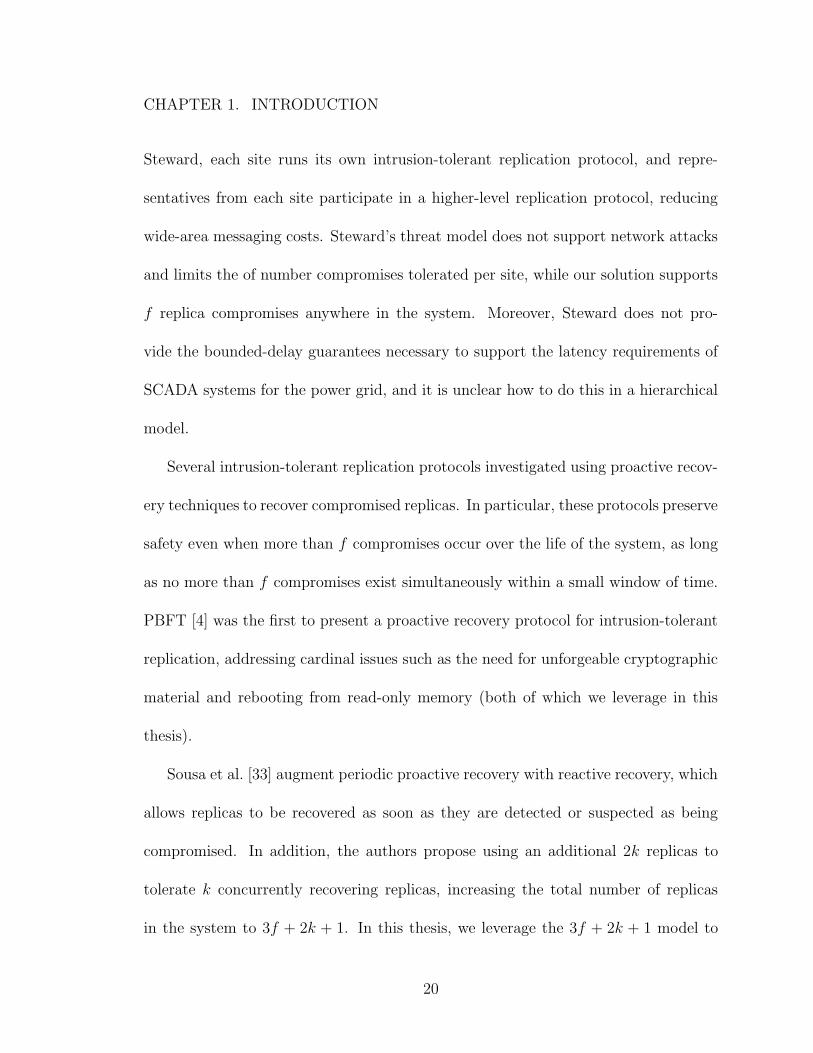
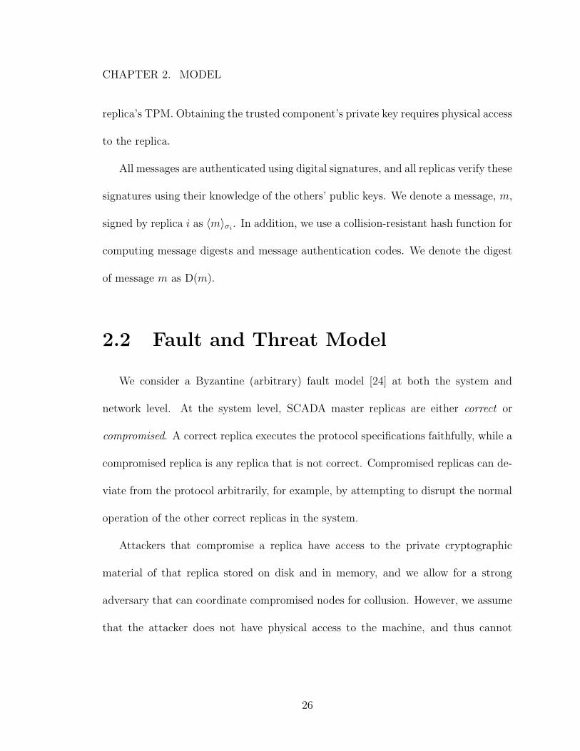
1.1 Standard SCADA architecture, consisting of a replicated SCADA mas-ter that manages physical equipment in the field and displays the gridstatus to human operators at the HMI. . . . . . . . . . . . . . . . . . 4
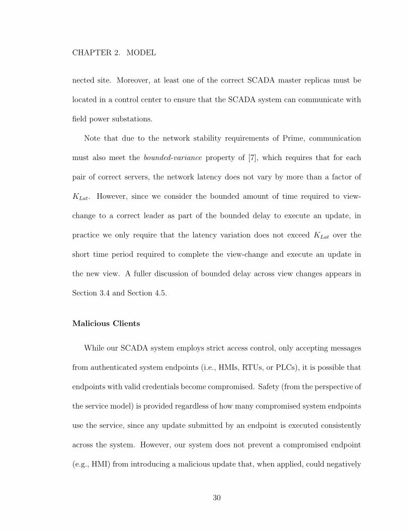
1.2 Modern resilient SCADA architecture using two control centers. Ahot-backup SCADA master is used within each control center, andthe cold-backup control center can be activated if the primary controlcenter fails. . . . . . . . . . . . . . . . . . . . . . . . . . . . . . . . . 7
3.1 Normal path of update through Prime (f = 1, k = 0). . . . . . . . . . 453.2 Example of Prime’s ordering matrix. Row i is the latest signed sum-
mary vector (po-aru) from replica i. Sorting each column j and takingthe 2f + k + 1th highest value indicates the requests from j that havebeen cumulatively pre-ordered by a quorum and are ready to be ordered. 46
3.3 Example of inconsistencies that can arise with proactive recoveries inan ephemeral approach. In the first step, the red compromised replicaassigns message m to sequence number x and orders it with 2f + k+1replicas (quorum) on one side of a partition. In the second step, one ofthe original replicas undergoes proactive recovery and comes back intoa different network partition. If the compromised replica now assignsm′ to x, it will be ordered by these 2f + k + 1 replicas, creating aninconsistency in the ordering regarding the content of message x. . . . 49
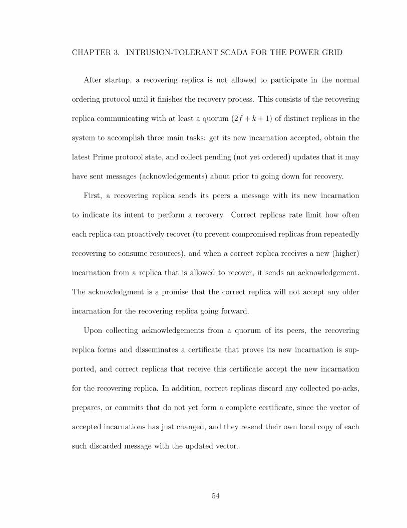
3.4 Example of the new Prime ordering matrix supporting proactive re-covery. Each vector now contains a tuple (incarnation, sequence) foreach other replica’s po-requests. Sorting each column j and taking the2f +k+1th highest value from the same incarnation quorum indicatesthe requests from j that have been pre-ordered by a quorum. If nosuch quorum exists, the last executed value is used. . . . . . . . . . . 57
3.5 Intrusion-Tolerant SCADA system architecture for a single control cen-ter deployment with 6 replicas (f = 1, k = 1). . . . . . . . . . . . . . 70
3.6 Example of an HMI created for a small power grid installation usingour pvbrowser-based solution. . . . . . . . . . . . . . . . . . . . . . . 73
xii
LIST OF FIGURES
3.7 Spire SCADA master replica, containing both the SCADA master andthe paired Prime daemon. The numbered arrows show the path of anupdate through the system originating from an HMI or RTU/PLC proxy. 75
3.8 Update latency histogram over 1-hour deployment in a single controlcenter with 6 replicas (f = 1, k = 1). . . . . . . . . . . . . . . . . . . 79
3.9 Update latencies over 1-hour deployment in a single control center with6 replicas (f = 1, k = 1). . . . . . . . . . . . . . . . . . . . . . . . . . 80
3.10 Latency in the presence of intrusions and proactive recoveries in a singlecontrol center deployment with 6 replicas (f = 1, k = 1). . . . . . . . 82
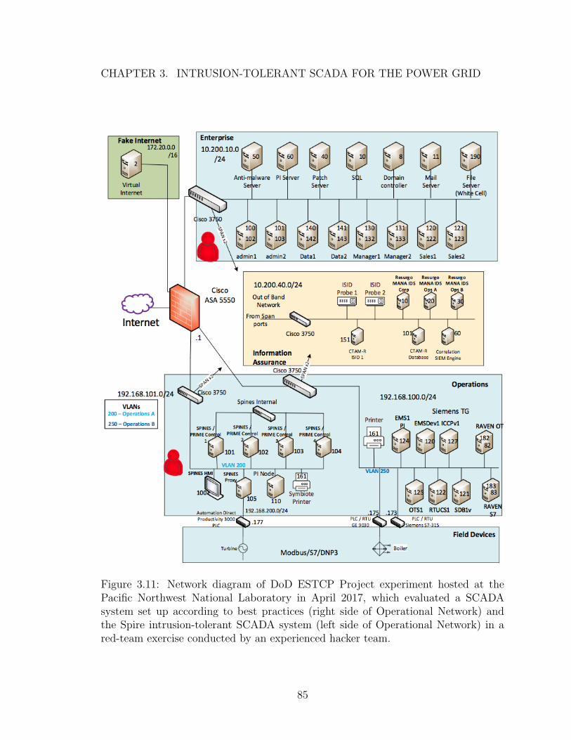
3.11 Network diagram of DoD ESTCP Project experiment hosted at thePacific Northwest National Laboratory in April 2017, which evaluateda SCADA system set up according to best practices (right side of Oper-ational Network) and the Spire intrusion-tolerant SCADA system (leftside of Operational Network) in a red-team exercise conducted by anexperienced hacker team. . . . . . . . . . . . . . . . . . . . . . . . . . 85
4.1 Illustration of specific SCADA system configurations’ ability to supportthe threat model we consider, including all combinations of a replicabeing unavailable due to proactive recovery, a site disconnection due tonetwork attack or failure, and an intrusion (SCADA master compromise). 92
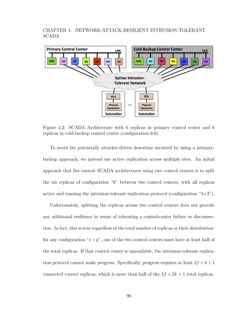
4.2 SCADA Architecture with 6 replicas in primary control center and 6replicas in cold-backup control center (configuration 6-6). . . . . . . . 96
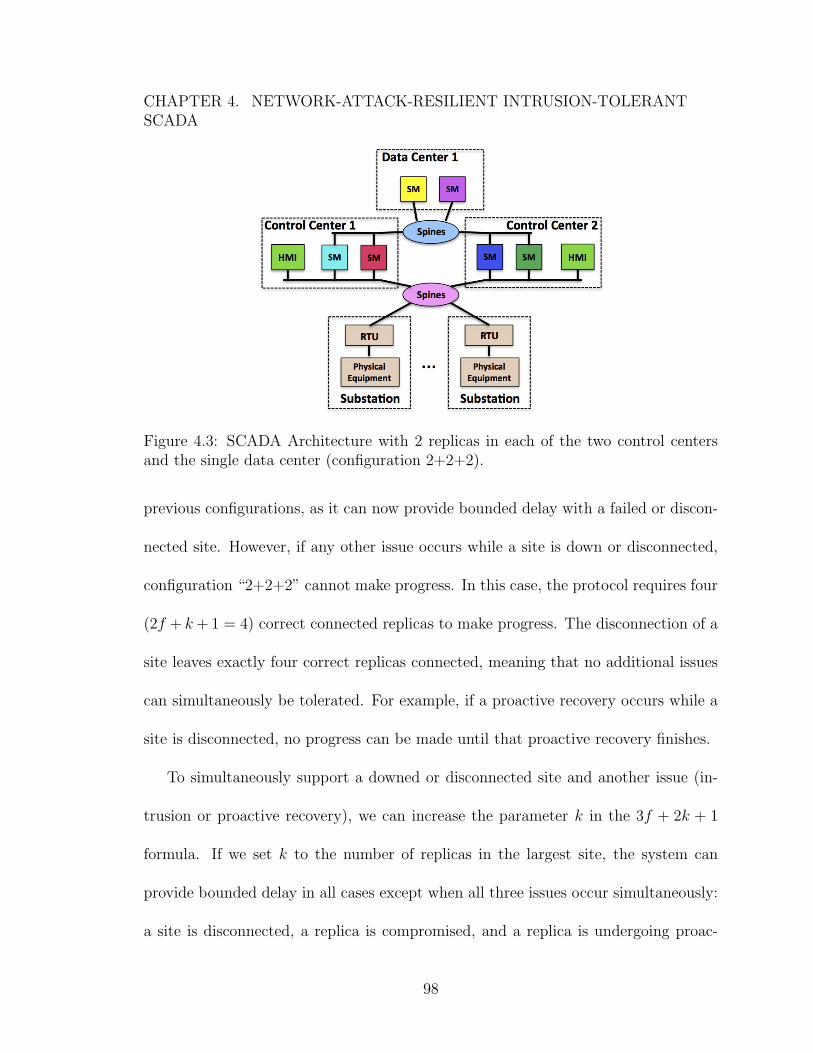
4.3 SCADA Architecture with 2 replicas in each of the two control centersand the single data center (configuration 2+2+2). . . . . . . . . . . . 98
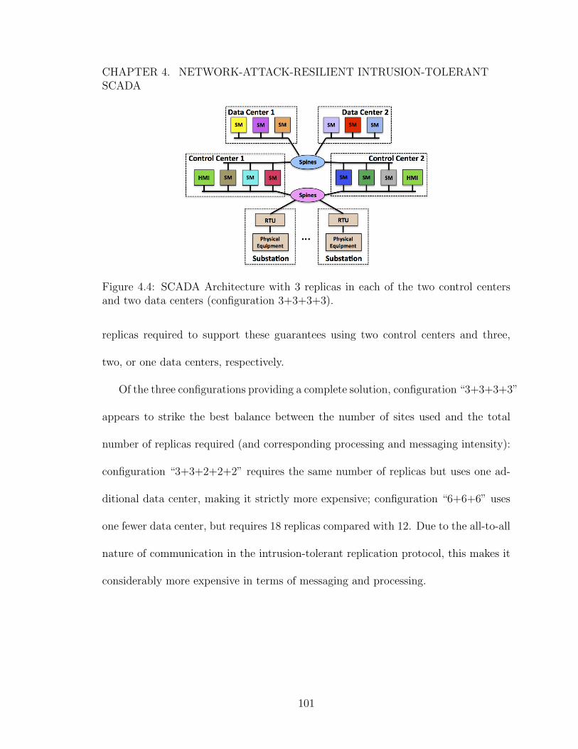
4.4 SCADA Architecture with 3 replicas in each of the two control centersand two data centers (configuration 3+3+3+3). . . . . . . . . . . . . 101
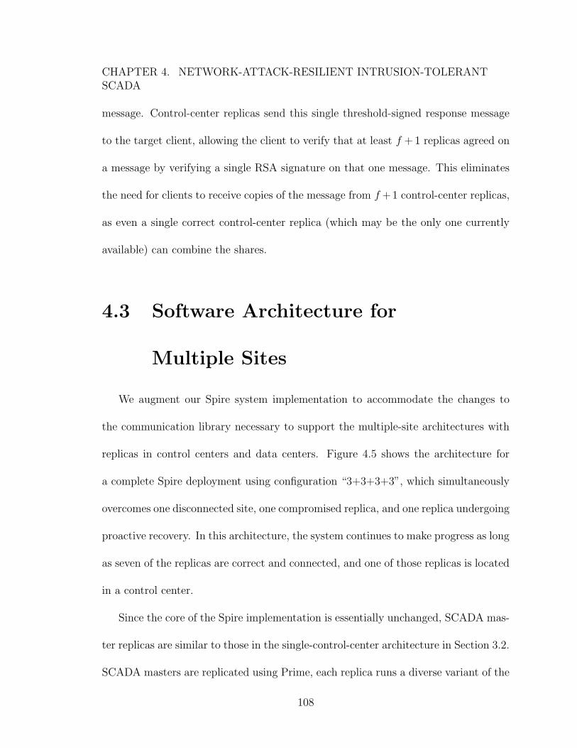
4.5 Intrusion-Tolerant SCADA system architecture for configuration “3+3+3+3”.1094.6 Updated Spire SCADA master replica for multiple-site architectures,
with threshold-signed response messages. The numbered arrows showthe path of an update through the system originating from an HMI orRTU/PLC proxy. . . . . . . . . . . . . . . . . . . . . . . . . . . . . . 116
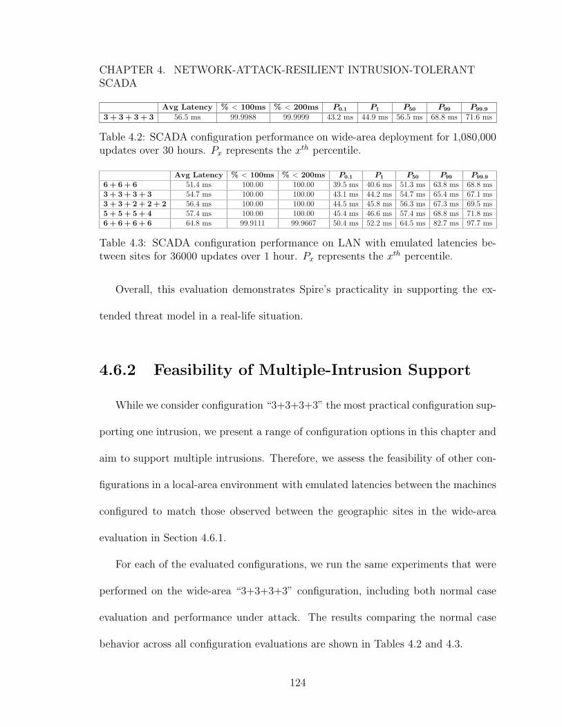
4.7 3+3+3+3 configuration. Update latency histogram over 30-hour wide-area deployment (13 updates over 100ms not visible). . . . . . . . . . 119
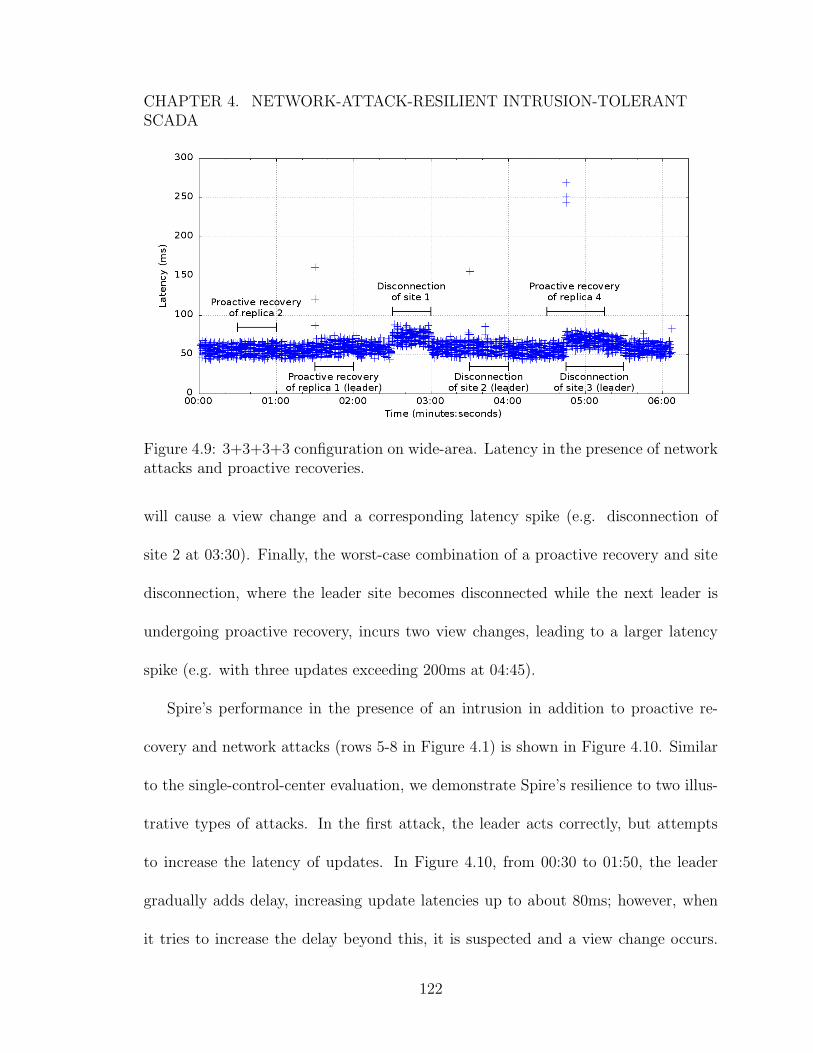
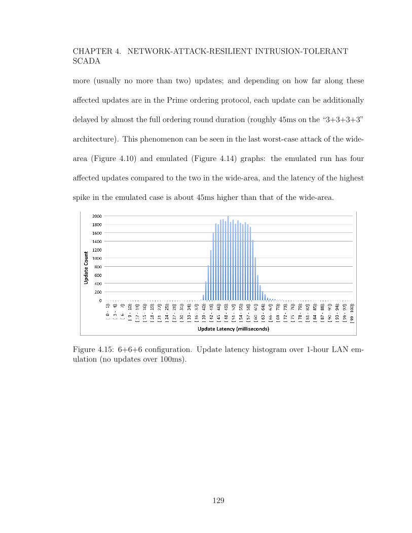
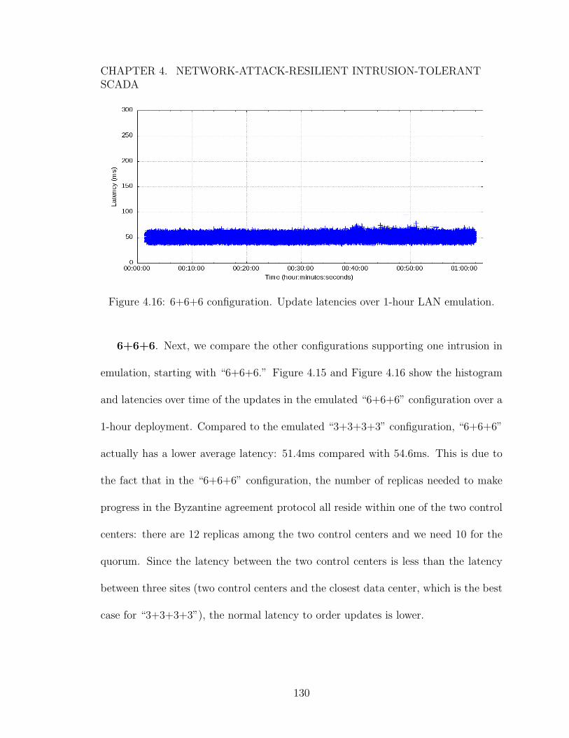
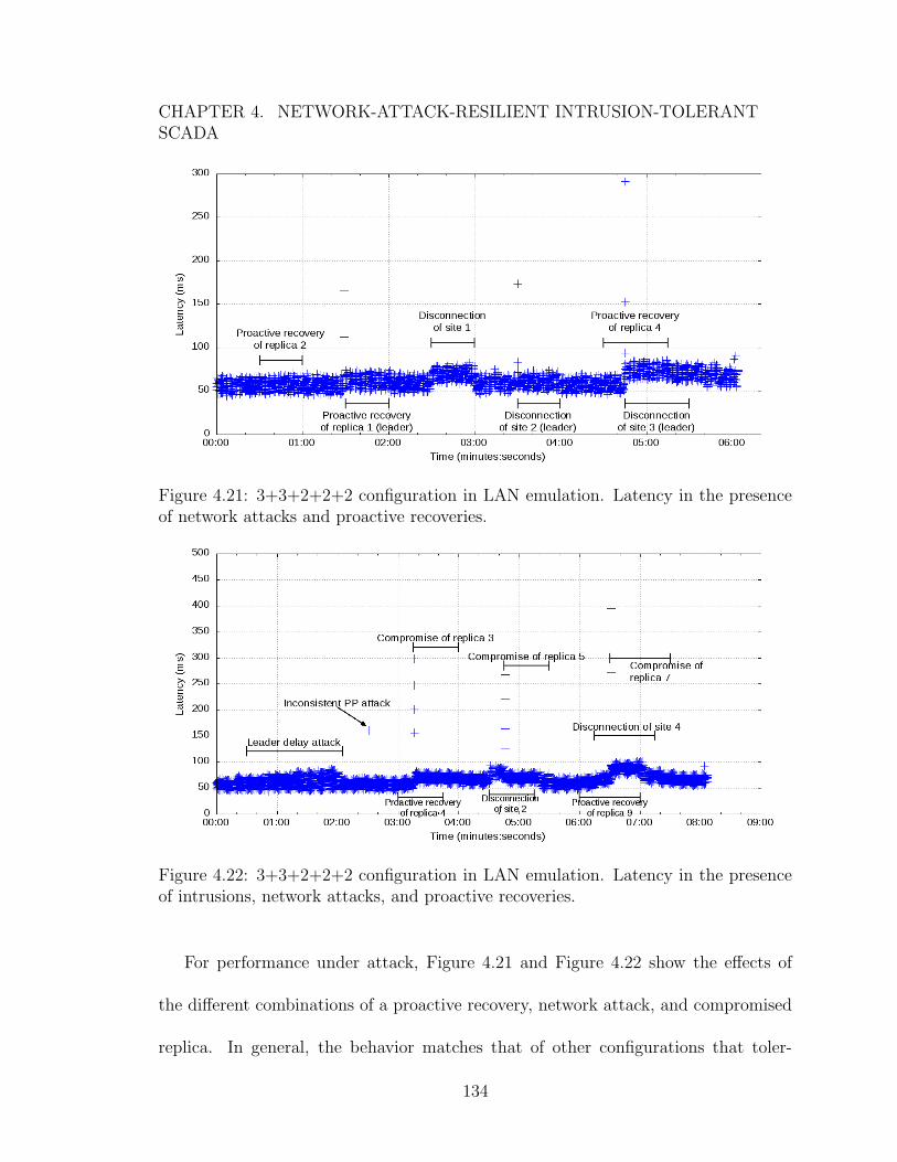
of network attacks and proactive recoveries. . . . . . . . . . . . . . . 1344.22 3+3+2+2+2 configuration in LAN emulation. Latency in the presence
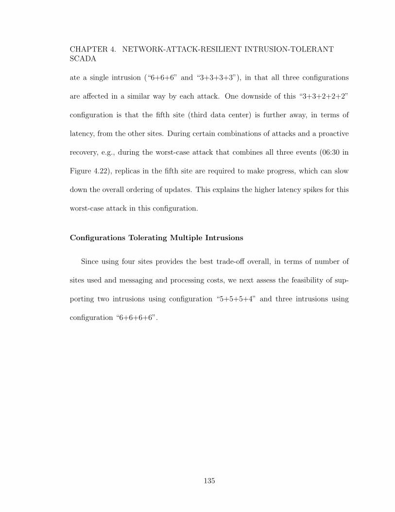
of intrusions, network attacks, and proactive recoveries. . . . . . . . . 1344.23 5+5+5+4 configuration. Update latency histogram over 1-hour LAN
emulation (no updates over 100ms). . . . . . . . . . . . . . . . . . . . 1364.24 5+5+5+4 configuration. Update latencies over 1-hour LAN emulation. 1374.25 5+5+5+4 configuration in LAN emulation. Latency in the presence of
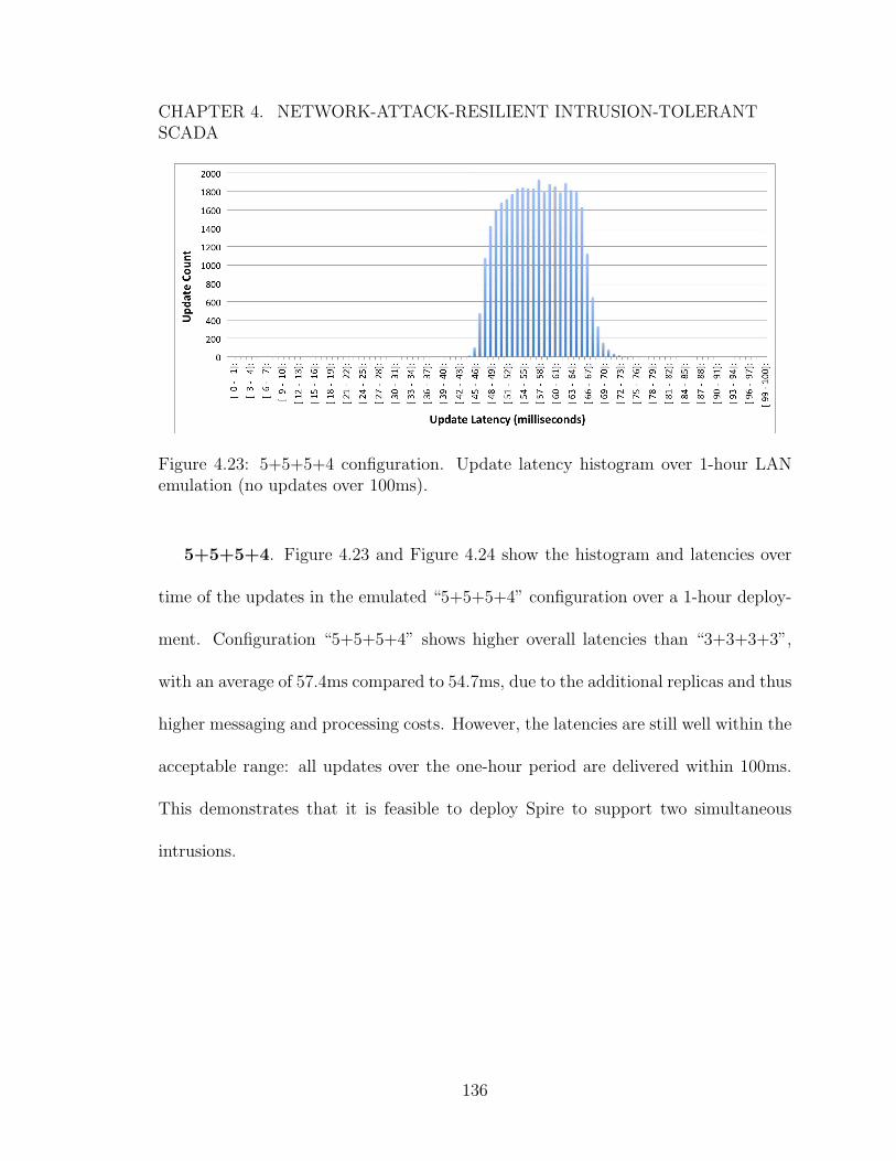
network attacks and proactive recoveries. . . . . . . . . . . . . . . . . 1374.26 5+5+5+4 configuration LAN emulation. Latency in the presence of
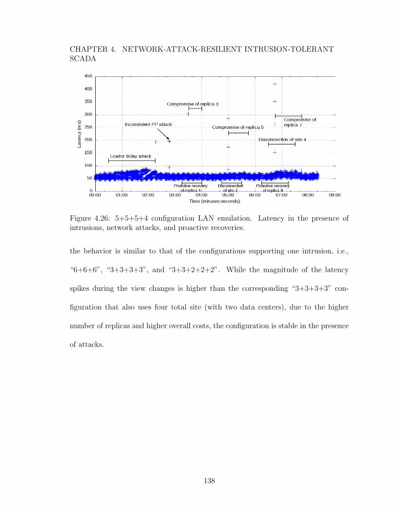
intrusions, network attacks, and proactive recoveries. . . . . . . . . . 1384.27 6+6+6+6 configuration. Update latency histogram over 1-hour LAN
emulation (32 updates over 100ms not visible). . . . . . . . . . . . . . 1394.28 6+6+6+6 configuration. Update latencies over 1-hour LAN emulation. 1404.29 6+6+6+6 configuration in LAN emulation. Latency in the presence of
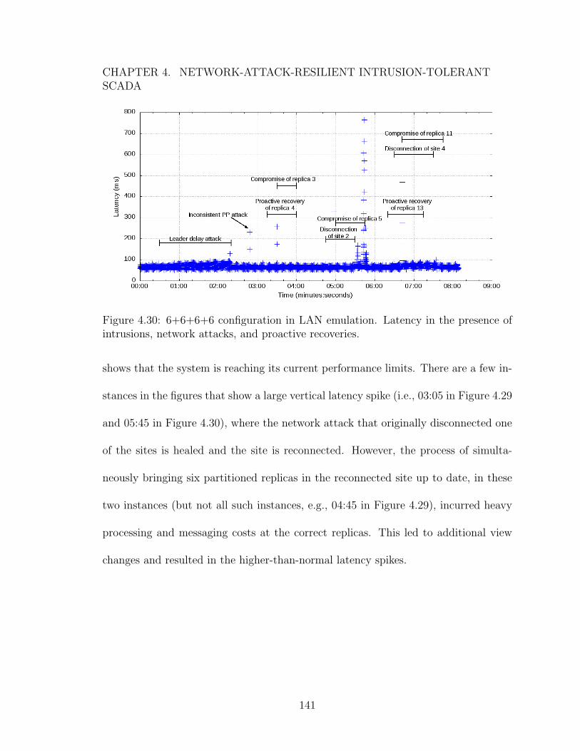
network attacks and proactive recoveries. . . . . . . . . . . . . . . . . 1404.30 6+6+6+6 configuration in LAN emulation. Latency in the presence of
intrusions, network attacks, and proactive recoveries. . . . . . . . . . 1415.1 SCADA architecture for 3+3+3+3 configuration (using two cloud data
centers) with only abstract state stored in the cloud SCADA masterreplicas. . . . . . . . . . . . . . . . . . . . . . . . . . . . . . . . . . . 148
xiv
Chapter 1
Introduction
Supervisory Control and Data Acquisition (SCADA) systems form the monitoring
and control backbone of the power grid. SCADA systems use a distributed architec-
ture to connect field devices and physical equipment located in power substations
with centralized control centers, enabling simultaneous control over a wide variety
of devices that combine to make up a typical grid installation. With this setup,
grid operators in a control center can monitor the status of the grid, detect abnor-
mal conditions, and issue control commands to manage the physical equipment in
substations.
With power as a fundamental and crucial aspect of life today, it is critical to en-
sure that SCADA systems are continuously available and operating correctly at their
expected level of performance. Failures and downtime of SCADA systems can lead to
grid equipment damage and extended power outages, which can severely impact ser-
1
CHAPTER 1. INTRODUCTION
vices that our society relies on, such as sanitation, communications, transportation,
and public safety, among many others. As a result, SCADA systems are high-value
targets for attack. In extreme cases, a successful cyberattack of a SCADA system
managing a critical electric utility could impact millions of people in the affected
geographic area.
Unfortunately, SCADA systems were never designed to withstand malicious at-
tacks; a large number of security vulnerabilities have been identified in a variety of
SCADA products, and security experts project that more exist that have yet to be dis-
covered [1,2]. Originally, SCADA systems were deployed on closed, private networks,
creating an “air gap” that isolated the systems (and any associated vulnerabilities)
from attackers. But today, more and more SCADA systems (and Industrial Control
Systems in general) are becoming connected to the Internet, exposing them to hostile
environments in which vulnerabilities can be exploited.
To date, the majority of efforts invested in securing SCADA systems have focused
on creating a strong perimeter defense to keep attackers out of the trusted environ-
ment. While this approach is necessary, it is only a partial solution. There have been
a number of reported attacks that have successfully penetrated perimeter defenses,
and in specific cases, shut down targeted equipment in substations to cause power
outages [3].
These examples demonstrate that additional security measures beyond a tradi-
tional perimeter defense are required to adequately protect our critical infrastructure.
2
CHAPTER 1. INTRODUCTION
To this end, intrusion tolerance (or Byzantine fault tolerance) principles can provide
a system with the ability to continue operating correctly even after part of that sys-
tem is compromised and under the control of an attacker. There has been extensive
work in creating and improving general-purpose intrusion-tolerant replication proto-
cols (e.g., [4–12]), and some work has even applied intrusion tolerance in the context
of SCADA systems [13–15].
However, none of the existing work on intrusion-tolerant replication is resilient
to sophisticated network attacks. Such attacks can completely disrupt the commu-
nication between system components, and in the case of SCADA, can impair the
ability to manage the grid without requiring any specialized knowledge of the power
domain. In addition, previous efforts to create intrusion-tolerant SCADA systems
have focused on integrating general-purpose intrusion-tolerant replication protocols
with existing SCADA systems. However, these SCADA systems were not designed
to support intrusion tolerance; there are important mismatches between the models
and performance needs of SCADA systems and those provided by existing intrusion-
tolerant technologies, resulting in solutions that are complex, difficult to extend, and
limited in scalability.
In this thesis, we create the first intrusion-tolerant SCADA system that simulta-
neously addresses system compromises and network attacks. The system is designed
from the ground up to support intrusion-tolerant replication that meets the strict
needs of SCADA for the power grid. We show that the system maintains high avail-
3
CHAPTER 1. INTRODUCTION
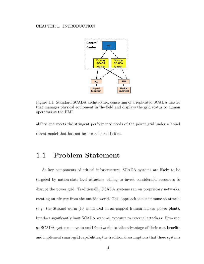
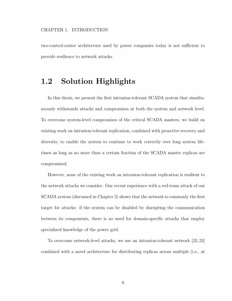
Figure 1.1: Standard SCADA architecture, consisting of a replicated SCADA masterthat manages physical equipment in the field and displays the grid status to humanoperators at the HMI.
ability and meets the stringent performance needs of the power grid under a broad
threat model that has not been considered before.
1.1 Problem Statement
As key components of critical infrastructure, SCADA systems are likely to be
targeted by nation-state-level attackers willing to invest considerable resources to
disrupt the power grid. Traditionally, SCADA systems ran on proprietary networks,
creating an air gap from the outside world. This approach is not immune to attacks
(e.g., the Stuxnet worm [16] infiltrated an air-gapped Iranian nuclear power plant),
but does significantly limit SCADA systems’ exposure to external attackers. However,
as SCADA systems move to use IP networks to take advantage of their cost benefits
and implement smart-grid capabilities, the traditional assumptions that these systems
4
CHAPTER 1. INTRODUCTION
are air-gapped and inaccessible to outside attackers no longer hold. Recent reports
show that SCADA systems are increasingly subject to attack [3, 17].
While today’s SCADA systems employ fault tolerance to overcome benign failures,
they were never designed to withstand malicious attacks. As shown in Figure 1.1,
SCADA systems typically use primary-backup approaches to provide recovery capa-
bilities, with a hot-backup of the central control server (the SCADA master) taking
over immediately if the primary master fails. The SCADA master is the critical
component responsible for collecting and logging data from Remote Terminal Units
(RTUs) and Programmable Logic Controllers (PLCs), presenting the current status of
the infrastructure (including detected problems) to a human operator via the Human-
Machine Interface (HMI), and issuing control commands to the RTUs and PLCs. The
RTUs and PLCs connect to the physical equipment in the power substations to trans-
late signals (e.g. current, phase, voltage) into digital data, send status updates to the
control center via a wide-area network, and control the physical devices based on su-
pervisory commands from the SCADA master. To provide real-time monitoring and
control capabilities, SCADA systems for the power grid must deliver device status
updates and supervisory commands within 100-200ms [18,19].
While the current primary-backup architectures provide sufficient resilience to
overcome benign failures, they are not adequate to cope with the hostile environments
that SCADA systems are now being exposed to. In these environments, SCADA
systems are vulnerable both to system-level compromises and network-level attacks.
5
CHAPTER 1. INTRODUCTION
System-level compromises of the SCADA master servers can have devastating
system-wide consequences. A compromised SCADA master can issue malicious com-
mands to damage physical power grid components and simultaneously manipulate
monitoring information to prevent operators from correcting or even being able to
observe the problem.
In addition, network-level attacks can disrupt or delay communication between the
SCADA system components, impairing the ability to manage the grid with the nec-
essary performance guarantees. For example, certain sophisticated denial-of-service
attacks (i.e., Crossfire [20] and Coremelt [21]) can target and isolate a site from the
rest of the network at the time of the attacker’s choosing, and can be made to persist
for an extended duration by evading normal IP rerouting mechanisms. If the target
of such an attack is a power substation in the field, the effect is localized and the
SCADA system may lose the ability to manage that portion of the grid. However,
if the target is the main control center containing the SCADA master servers, the
entire grid can effectively be left unmanaged.
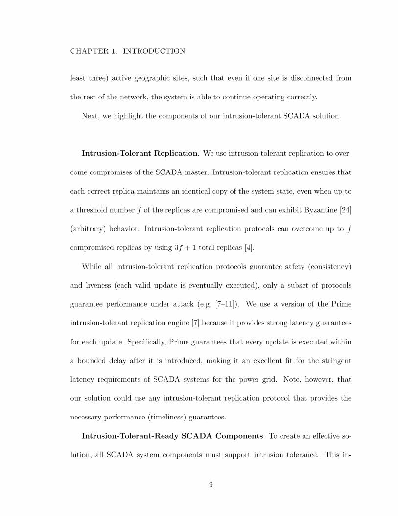
Clearly, a SCADA system architecture containing more than one site is required;
and in fact, state-of-the-art SCADA systems today (as shown in Figure 1.2) utilize
a cold-backup control center that can be activated within a couple of hours if the
primary control center fails. However, even this primary-backup architecture span-
ning two geographically-dispersed locations cannot sufficiently overcome sophisticated
network attacks. A cold-backup approach inherently incurs downtime to bring the
6
CHAPTER 1. INTRODUCTION
Figure 1.2: Modern resilient SCADA architecture using two control centers. A hot-backup SCADAmaster is used within each control center, and the cold-backup controlcenter can be activated if the primary control center fails.
backup online. When a control center fails as the result of a benign problem, the
downtime incurred while activating the backup is likely to occur at a non-critical
time, and therefore is considered acceptable today; however, a malicious attack can
be intentionally launched at the worst possible time (e.g. during a major snowstorm
or during a coordinated large-scale attack in multiple domains).
To avoid the inherent downtime associated with cold-backup approaches, we can
consider switching to a hot-backup approach, where the backup control center is
always active and ready to take over should the primary fail. However, even this
active hot-backup approach is not sufficient due to its vulnerability to the “split-
brain” problem: if the primary and backup sites cannot communicate (either due
to benign network failures or malicious network attacks), they will both attempt to
assume the role of the primary and can issue conflicting control commands, leading
to inconsistent behavior. In fact, as we will demonstrate, any deployment using the
7
CHAPTER 1. INTRODUCTION
two-control-center architecture used by power companies today is not sufficient to
provide resilience to network attacks.
1.2 Solution Highlights
In this thesis, we present the first intrusion-tolerant SCADA system that simulta-
neously withstands attacks and compromises at both the system and network level.
To overcome system-level compromises of the critical SCADA masters, we build on
existing work on intrusion-tolerant replication, combined with proactive recovery and
diversity, to enable the system to continue to work correctly over long system life-
times as long as no more than a certain fraction of the SCADA master replicas are
compromised.
However, none of the existing work on intrusion-tolerant replication is resilient to
the network attacks we consider. Our recent experience with a red-team attack of our
SCADA system (discussed in Chapter 3) shows that the network is commonly the first
target for attacks: if the system can be disabled by disrupting the communication
between its components, there is no need for domain-specific attacks that employ
specialized knowledge of the power grid.
To overcome network-level attacks, we use an intrusion-tolerant network [22, 23]
combined with a novel architecture for distributing replicas across multiple (i.e., at
8
CHAPTER 1. INTRODUCTION
least three) active geographic sites, such that even if one site is disconnected from
the rest of the network, the system is able to continue operating correctly.
Next, we highlight the components of our intrusion-tolerant SCADA solution.
Intrusion-Tolerant Replication. We use intrusion-tolerant replication to over-
come compromises of the SCADA master. Intrusion-tolerant replication ensures that
each correct replica maintains an identical copy of the system state, even when up to
a threshold number f of the replicas are compromised and can exhibit Byzantine [24]
(arbitrary) behavior. Intrusion-tolerant replication protocols can overcome up to f
compromised replicas by using 3f + 1 total replicas [4].
While all intrusion-tolerant replication protocols guarantee safety (consistency)
and liveness (each valid update is eventually executed), only a subset of protocols
guarantee performance under attack (e.g. [7–11]). We use a version of the Prime
intrusion-tolerant replication engine [7] because it provides strong latency guarantees
for each update. Specifically, Prime guarantees that every update is executed within
a bounded delay after it is introduced, making it an excellent fit for the stringent
latency requirements of SCADA systems for the power grid. Note, however, that
our solution could use any intrusion-tolerant replication protocol that provides the
necessary performance (timeliness) guarantees.
Intrusion-Tolerant-Ready SCADA Components. To create an effective so-
lution, all SCADA system components must support intrusion tolerance. This in-
9
CHAPTER 1. INTRODUCTION
cludes a SCADA master that is able to be replicated using intrusion-tolerant repli-
cation and HMIs, RTUs, and PLCs that can correctly interact with the replicated
SCADA master. However, existing SCADA systems were not designed to support
intrusion tolerance; there are several important mismatches between the models and
performance needs of SCADA systems and those provided by existing intrusion-
tolerant technologies.
Therefore, we design our SCADA system from the ground up, with intrusion
tolerance as a core design principle: it includes a SCADA master designed from
scratch to support intrusion-tolerant replication, RTU/PLC proxies that allow the
SCADA master to interact with RTUs and PLCs in an event-driven intrusion-tolerant
manner, and an intrusion-tolerant communication library that connects HMIs and
RTU/PLC proxies to the replicated SCADA masters. The result is a scalable SCADA
system that ensures all correct SCADA master replicas deterministically process the
same updates in the same order.
Diversity. Intrusion-tolerant replication protocols only guarantee correctness as
long as the number of compromised replicas does not exceed the tolerated threshold f .
However, if all replicas in the system are identical copies of one another, an attacker
who successfully exploits one replica can simply reuse the same exploit to compromise
all of the replicas in the system.
To prevent an attacker from gaining control of more than f replicas, the sys-
tem must ensure that the replicas present diverse attack surfaces. Diversity can be
10
CHAPTER 1. INTRODUCTION
achieved using approaches such as N-version programming [25,26], operating system
diversity [27], or software diversification at compilation or run time [28–31]. We use
the MultiCompiler [28], which employs techniques such as stack padding, no-op inser-
tion, equivalent instruction substitution, and function reordering to diversify the code
layout of an application. The MultiCompiler uses a 64-bit random seed to generate
diversity from a large entropy space, making it unlikely that the same attack on the
codebase will successfully compromise any two distinct variants.
Proactive Recovery. Even if replicas are sufficiently diverse, given enough
time, a dedicated attacker will eventually be able to craft enough distinct attacks to
compromise more than f replicas. Therefore, it is necessary to use proactive recovery
to ensure survivability over the lifetime of the system (which can be years for SCADA
systems) [4, 32].
In proactive recovery, each replica is periodically brought down and restarted
from a known clean state (removing any compromises) with a new diverse variant
of the software (and potentially of the entire operating system) that is with high
probability different from all past and future variants. This makes the job of the
attacker significantly harder, as they now must simultaneously compromise more than
f replicas within a limited time window. To maintain availability in the presence of
both f intrusions and k simultaneous proactive recoveries, a system with 3f + 1
replicas (e.g. Prime) must be extended to use 3f + 2k + 1 total replicas [33].
11
CHAPTER 1. INTRODUCTION
Intrusion-Tolerant Network. While intrusion-tolerant replication (with diver-
sity and proactive recovery) ensures correct operation despite SCADA-master com-
promises, it does not provide resilience to network attacks. If an attacker disrupts the
communication between the control center and the power substations, the SCADA
system loses its ability to monitor and control the power grid, even if all the SCADA
masters are working correctly. Therefore, a resilient networking foundation is essential
for a complete intrusion-tolerant SCADA solution.
We use the Spines overlay messaging framework [22], which provides the ability to
deploy an intrusion-tolerant network [23]. Spines uses an overlay approach to over-
come attacks and compromises in the underlying network: overlay sites are connected
with redundancy, forcing an attacker to successfully attack many links in the under-
lying networks to disrupt communication to a single site. By using multihoming at
each site, Spines can leverage multiple underlying networks (e.g., ISP backbones) to
tolerate the complete failure of one or more underlying networks. To overcome com-
promises of the overlay nodes, intrusion-tolerant protocols authenticate all traffic,
employ redundant dissemination, and enforce fairness [23].
Multiple Active Geographic Sites. The intrusion-tolerant network protects
against large-scale network disruption, overcomes malicious routing attacks, and sub-
stantially increases the effort and resources required to launch a successful denial of
service attack. However, because SCADA systems are high-value targets, it is likely
that dedicated nation-state-level attackers will invest considerable resources to dis-
12
CHAPTER 1. INTRODUCTION
rupt these systems. With enough resources, it is possible to execute sophisticated
denial of service attacks that can target a specific site and isolate it from the rest
of the network, such as the Coremelt [21] and Crossfire [20] attacks. However, we
believe that it is nearly infeasible for an attacker to create the complete simultaneous
meltdown of multiple ISP backbones necessary to target and disconnect multiple sites
when using the intrusion-tolerant network (discussed further in Section 4.4.1).
Therefore, to be truly resilient to network attacks, the SCADA system must con-
tinue to operate correctly even when one of the control centers is disconnected from
the rest of the network. To overcome these sophisticated attacks, we develop a novel
framework that distributes replicas across three or more active sites. As a result,
even if an attacker is able to target and isolate a control center from the rest of the
network, the SCADA system will continue to operate correctly and remain available
as long as the number of compromises in the rest of the system does not exceed the
tolerated threshold.
To make our architecture viable for deployment, it must fit the current power
company model that budgets for and deploys no more than two control centers that
can control physical devices in substations. Our novel architecture allows the two
control centers to be augmented with one or more commodity data centers that do
not need to control field devices, providing the same resilience at a feasible cost.
Spire. The system design is implemented in the Spire intrusion-tolerant SCADA
system [34], which is available as open source. We deploy and evaluate Spire in
13
CHAPTER 1. INTRODUCTION
several architectures and configurations, both in normal conditions and while under
attack. A single-control-center deployment of Spire was recently tested in a red-team
experiment, during which an experienced hacker team completely compromised a tra-
ditional SCADA system setup according to best practices, but was unable to impact
Spire’s guarantees over several days of attack. In addition, a wide-area deployment
of Spire, using two control centers and two data centers, spanning 250 miles (similar
to large U.S. power grids), delivered nearly 99.999% of all SCADA updates initiated
over a 30-hour period within 100ms. Out of 1.08 million updates, only 13 took over
100ms, and only one of those 13 exceeded 200ms. These results demonstrate that
Spire provides meaningful security advantages over traditional SCADA systems and
that Spire can meet the latency requirements of SCADA for the power grid.
Resilient SCADA as a Service. Successfully translating this research to de-
ployment in the independently-operated electric utility installations requires that each
utility be proficient in state-of-the-art intrusion-tolerance principles and secure net-
work and machine configuration. Given the current power grid ecosystem, such a
level of expertise is unlikely to exist in the near future, creating a natural fit for a
service provider solution that can provide intrusion tolerance to a large number of
installations at a feasible cost.
Despite the benefits, using a cloud-based SCADA provider raises security and
confidentiality issues for power utilities regarding sensitive information. To address
these concerns, we present a vision for leveraging the benefits of the cloud to manage
14
CHAPTER 1. INTRODUCTION
intrusion-tolerant SCADA systems without revealing sensitive information by provid-
ing only an abstract representation of that data to the cloud.
The primary contributions of this thesis are:
• We invent the first intrusion-tolerant SCADA system that simultaneously ad-
dresses system compromises and network attacks. To support this expanded
threat model, we develop a novel architecture that distributes SCADA master
replicas across the required three or more active geographic sites.
• We extend the architecture to leverage commodity data centers (that may not
be able to control field devices) to avoid constructing additional power company
control centers, reducing costs and making the architecture viable for deploy-
ment.
• We present a SCADA system designed from the ground up with intrusion tol-
erance and security in mind. The system uses a SCADA master built from
scratch and RTU/PLC proxies to enable a scalable event-driven architecture
rather than a traditional polling-based approach. The system maintains back-
wards compatibility with existing RTUs and PLCs that speak standard SCADA
communication protocols, while isolating the usage of these insecure standards
to a single connection behind the secure proxies.
15
CHAPTER 1. INTRODUCTION
• We implement our system design as the Spire intrusion-tolerant SCADA system
and make it available as open source.
• We deploy and evaluate Spire in a single-control-center architecture and test
it in a red-team experiment. Spire successfully withstood several days of at-
tacks, demonstrating that Spire provides meaningful security advantages over
the traditional SCADA systems that were assessed and compromised.
• We deploy and evaluate Spire on a wide-area network with a geographic foot-
print similar to that of large U.S. power grids. We show that the system can
meet the stringent latency requirements of the power grid.
• We describe a vision for providing resilient SCADA as a service to power grid
installations to create a coordinated grid defense that preserves the privacy of
individual installations.
1.3 Thesis Organization
The remainder of this thesis is organized as follows:
• The next section presents previous research in intrusion-tolerant replication,
intrusion-tolerant SCADA systems, and complimentary intrusion-handling ap-
proaches.
• Chapter 2 presents the system model, threat model, and service properties.
16
CHAPTER 1. INTRODUCTION
• Chapter 3 presents our intrusion-tolerant SCADA system for the power grid,
including the various subcomponents and the Spire system implementation. In
addition, the chapter provides an evaluation of a single-control-center deploy-
ment of Spire and details the results of a recent red-team experiment.
• Chapter 4 presents our network-attack-resilient architecture that distributes
replicas across multiple active geographic sites to overcome an isolated site
due to network attacks. We deploy Spire in several wide-area configurations
and present an evaluation of Spire both in normal conditions and while under
attack.
• Chapter 5 describes our vision for resilient SCADA as a service that uses
of the total 3f + 2k + 1 replicas) can communicate with one another at any given
time. In our broad threat model, in addition to system-level compromises and proac-
tive recoveries, we assume that at most one site can be disconnected from the rest of
the network due to sophisticated network attacks. Therefore, in the worst case, the
connected set of correct replicas must exclude the f compromised replicas, the one
replica undergoing proactive recovery, and all of the replicas located in the discon-
29
CHAPTER 2. MODEL
nected site. Moreover, at least one of the correct SCADA master replicas must be
located in a control center to ensure that the SCADA system can communicate with
field power substations.
Note that due to the network stability requirements of Prime, communication
must also meet the bounded-variance property of [7], which requires that for each
pair of correct servers, the network latency does not vary by more than a factor of
KLat. However, since we consider the bounded amount of time required to view-
change to a correct leader as part of the bounded delay to execute an update, in
practice we only require that the latency variation does not exceed KLat over the
short time period required to complete the view-change and execute an update in
the new view. A fuller discussion of bounded delay across view changes appears in
Section 3.4 and Section 4.5.
Malicious Clients
While our SCADA system employs strict access control, only accepting messages
from authenticated system endpoints (i.e., HMIs, RTUs, or PLCs), it is possible that
endpoints with valid credentials become compromised. Safety (from the perspective of
the service model) is provided regardless of how many compromised system endpoints
use the service, since any update submitted by an endpoint is executed consistently
across the system. However, our system does not prevent a compromised endpoint
(e.g., HMI) from introducing a malicious update that, when applied, could negatively
30
CHAPTER 2. MODEL
impact the SCADA system or managed physical equipment. This is a concern when
we consider safety (correctness) holistically for our complete SCADA system and not
just from the perspective of the intrusion-tolerant replication protocol.
Tolerating certain malicious actions from compromised system endpoints is pos-
sible. For example, to protect against a compromised HMI injecting malicious up-
dates, expert SCADA domain knowledge could be used to screen updates coming
from HMIs; any update that is detected as abnormal or malicious can be rejected
before it is executed by the system [47]. For the most critical HMI updates that can
severely affect the grid, requiring the “two-person concept” for execution can provide
additional protection. This technique, originally designed to prevent a single per-
son from accidentally or maliciously launching nuclear weapons, can prevent a single
compromised HMI or insider threat (e.g., disgruntled employee) controlling an HMI
from independently forcing the SCADA system to execute critical commands.
Employing these additional techniques presents a trade-off. On one hand, the
techniques create a system that is more resilient against compromised endpoints; on
the other hand, the techniques introduce additional cost and complexity to the already
nontrivial SCADA solution we are proposing, resulting in a less usable system. It is
up to the system designer to determine whether using these techniques are worth the
additional costs.
Given that resources are limited, we focus our efforts on tolerating compromises
of only the SCADA master, the most critical component. Nevertheless, our SCADA
31
CHAPTER 2. MODEL
architecture provides protection for all system endpoints (HMIs, RTUs, and PLCs)
using a proxy-based approach. The network between SCADA components is made se-
cure and intrusion-tolerant by connecting each endpoint to a proxy. The proxies com-
municate through the Spines intrusion-tolerant network (described in Section 3.1.6)
and sit directly next to the components they protect. While such a solution does not
provide full intrusion tolerance, it substantially enhances the overall resistance of the
system to intrusions and is practical for near-term deployment.
Supporting Our Assumptions
The safety and bounded delay guarantees of the service model rely on the two
key assumptions we stated earlier: no more than f of the SCADA master replicas
can be compromised simultaneously, and at most one site can be disconnected due to
network attacks at any given time.
To support the assumption on number of compromised replicas, we use diversity
and proactive recovery. We diversify the SCADA master replicas using the Multi-
Compiler [49], which generates diverse variants of the software from a large entropy
space, making it highly unlikely that the same attack will successfully compromise
two distinct variants. Combined with proactive recovery, where periodically a replica
is rejuvenated from a known clean state with a distinct new variant, an attacker is
forced to compromise more than f diverse variants within a confined time window
32
CHAPTER 2. MODEL
(rather than over the entire lifetime of the system) to violate the assumptions. As a
result, the job of the attacker is made significantly harder.
To support the assumption on sites’ network connectivity, we use the intrusion-
tolerant network as the foundation for all communication in the SCADA system.
This network is built as a resilient overlay that makes use of multiple Internet Service
Provider (ISP) backbones and connects sites with redundancy, forcing an adversary to
successfully attack many links in the underlying networks in order to completely cut
communication to a single site (more details on this resilient network architecture are
presented in Section 4.4.1). The intrusion-tolerant network withstands compromises
both in the underlying network and at the overlay level.
With this foundation, it is extremely difficult for an attacker to disconnect a site
(i.e., isolate a control center) from the rest of the network. Though it is difficult, we
believe a dedicated state-sponsored attacker can invest sufficient resources to discon-
nect a single targeted site. However, we believe that the intrusion-tolerant network
makes it nearly infeasible for an attacker to create the complete simultaneous melt-
down of multiple ISP backbones necessary to target and disconnect multiple sites,
supporting our threat model that considers at most one successfully disconnected
site.
33
CHAPTER 2. MODEL
2.4 Supporting a SCADA Historian
To support the real-time monitoring and control aspect of SCADA for the power
grid, our SCADA masters continuously collect and deliver the latest (i.e., most recent)
updates from RTUs and PLCs in substations. Updates are applied with overtaken-
by-event semantics: the value stored for each device is replaced with the new value
in the latest update, maintaining (as much as possible) an accurate model of the grid
at that instant from which to make decisions.
In addition to real-time monitoring and control, commercial SCADA masters com-
monly also maintain a historian, which logs SCADA system updates and commands
to a database for analysis (e.g., to calculate trends over time). In this setting, SCADA
master replicas that fall behind or lose their state must recover the missing history
to catch up. Ensuring that these replicas can recover the history in the presence of
other compromised replicas requires application-specific state checkpointing and an
efficient state transfer protocol [4,37]. In practice, these protocols must be tailored to
the application being replicated (in our case a specific historian), taking into account
specific implementation details of both the application and its underlying database.
In some cases, the application or database may even need to be altered to guarantee
that checkpointing is deterministic and will be consistent across all correct replicas
at any point in the order of execution.
In this thesis, we focus on providing an intrusion-tolerant SCADA solution that
meets the stringent timeliness requirements of the power grid under a broad threat
34
CHAPTER 2. MODEL
model that has not been considered before. Our SCADA system features a SCADA
master built from scratch to natively support intrusion-tolerant replication and pro-
vide real-time monitoring and control.
Currently, our SCADA master does not have a historian. In our setting, SCADA
master replicas that fall behind or lose their state can quickly catch up solely by
obtaining the latest set of RTU/PLC updates from other up-to-date replicas. And in
extreme cases, e.g., if all replicas experience a crash-fault and lose their state, replicas
can go directly to the source and poll each of the RTUs and PLCs to obtain the latest
set of updates. As a result, we use an ephemeral approach for our SCADA master,
and consider supporting a historian beyond the scope of this thesis.
While our SCADA master does not currently have a historian, it does implement
key functionality that allows it to be extended to support historians in the future. In
particular, the SCADA master uses signalling between the replication layer and appli-
cation layer to instruct the application to create snapshots of its state at synchronized
points of execution and transfer these snapshots to replicas that have fallen behind
(see Section 3.1.3 for further details). To support a historian, the same signalling
framework can be combined with the recovery protocols we describe in Platania et
al. [37]. This work presents an algorithm for supporting applications with large state,
including state checkpointing and transfer strategies. In addition, the work presents
several trade-offs that the system designer can choose from, such as two different state
transfer strategies that prioritize either fast data retrieval or minimal bandwidth us-
35
CHAPTER 2. MODEL
age. By choosing the appropriate trade-offs and tailoring the state checkpointing
strategies to the specific implementation details of the target historian, the system
designer can create a SCADA master solution that supports the target historian.
Note on Persistency
It is important to note that throughout the above discussion on supporting a
SCADA historian, the SCADA masters use an ephemeral approach to maintain state;
no persistent solution is used. At first, this may seem incorrect. Replicas using an
ephemeral approach lose their copy of the state after a crash or proactive recovery,
and the historian database should be preserved across these events. However, as long
as recovering replicas can collect f +1 matching copies (or one copy and f matching
digests) of the state from other replicas in the system, they can reconstruct a correct
copy of the state.
Under the service model of the thesis (Section 2.3), there are at most f simulta-
neous compromises and k simultaneous replicas undergoing proactive recovery. As a
result, under this model, at least f + 1 correct replicas are available to help replicas
during a recovery. In fact, under this model, there are always at least 2f + k + 1
correct replicas available at any given time: 3f + 2k + 1 total - f compromises - k
recoveries = 2f + k + 1 correct replicas.
Although a persistent approach is not required under this model, there are two
general scenarios in which it is necessary.
36
CHAPTER 2. MODEL
• To enable the state validation optimization during proactive recovery
With an ephemeral approach, replicas that undergo proactive recovery lose their
state and rely on state transfer to reconstruct a correct copy of the state. In contrast,
a replica with persistent state has the ability to first validate its copy of the state with
other peer replicas before performing state transfer. If the state correctly validates
with at least f + 1 other replicas, which is typically the case when a correct replica
undergoes recovery, no state transfer is needed. This effectively reduces the cost and
completion time of proactive recovery in the typical benign case, which is especially
useful if the application state is quite large. Note that similar to state checkpointing,
state validation must be tailored to the specific application to ensure validation is
deterministic and efficient. The recovery protocols we describe in [37] also include
state validation strategies for a persistent state solution.
However, state validation is not always helpful. A recovering replica that was
previously compromised may have an invalid copy of the state or may be missing
state altogether. In this worst case, the replica needs a complete state transfer of the
state from its peers.
To guarantee correctness, proactive recovery protocols and models (e.g., [37]) must
budget sufficient time and resources to support this worst-case scenario during every
proactive recovery. While state validation is a useful optimization in practice, it
cannot be a requirement. In contrast, state transfer of consistent checkpoints, which
is utilized in both persistent and ephemeral approaches, is ultimately what is required
37
CHAPTER 2. MODEL
to support all recovery cases. Recovering replicas in an ephemeral approach are simply
viewed as worst-case failures that require a complete state transfer.
• To preserve application history after the simultaneous crash of more than f+2k
replicas out of the 3f + 2k + 1 total replicas
If more than f + 2k replicas simultaneously crash when using an ephemeral ap-
proach, there are less than 2f + 1 replicas remaining in the system with state. Since
up to f of these remaining replicas can be compromised, there may be less than the
required f+1 replicas available to help a recovering replica reconstruct a correct copy
of the state. In this case, the application history can become unrecoverable across the
system. In contrast, using a persistent approach allows replicas to retain their state
across restarts, ensuring that the application history is not lost when many (or even
all) replicas crash. Persistency would therefore be required if this failure scenario was
covered by the model.
While such a failure model is more severe in terms of the number of simultaneous
crashes compared with the service model of this thesis, the ability to support such
a large fraction of crashing replicas can be useful in practice. For example, system
administrators may want to bring down all replicas at once to perform system-wide
maintenance. However, such operational concerns (and the expanded crash model)
are beyond the scope of this work and are a promising avenue for future work.
38
Chapter 3
Intrusion-Tolerant SCADA for the
Power Grid
This chapter presents the design and specification of a scalable intrusion-tolerant
SCADA system that overcomes attacks and compromises at both the system and
network level. The system combines several novel components with proven open-
source technologies to provide a resilient and secure solution that meets the stringent
performance requirements of SCADA systems for the power grid. The system design
is implemented in the Spire intrusion-tolerant SCADA system [34], which is available
as open source.
We present a SCADA system architecture that is designed to serve a power grid
managed and operated by a single control center. We deploy Spire in this single-
control-center architecture and assess its ability to support the timeliness require-
39
CHAPTER 3. INTRUSION-TOLERANT SCADA FOR THE POWER GRID
ments of the power grid, both in normal conditions and while under attack. Finally,
we report the positive and promising results of a recent red-team experience, in which
an experienced hacker team attacked both a commercial SCADA system setup ac-
cording to best practices and our Spire system.
3.1 Intrusion-Tolerant SCADA System
While there are several different components in SCADA systems that can cause
damage if compromised, the SCADA master is the most critical component, since
compromises of the master can have devastating system-wide consequences. A com-
promised SCADA master can issue malicious commands to damage physical power
grid components and can manipulate monitoring information to prevent operators
from correcting or even being able to observe the problem. Therefore, we focus our
efforts to protect the SCADA master, using intrusion tolerance techniques to over-
come compromises of the SCADA master.
However, existing SCADA systems were not designed to support intrusion tol-
erance. Previous work that added intrusion tolerance to an existing SCADA prod-
uct [15], as well as our initial efforts to add intrusion tolerance to an existing open-
source SCADA system, observed important mismatches between the models and per-
formance needs of SCADA systems and those provided by existing intrusion-tolerant
technologies. Conventional SCADA systems are server-driven, with SCADA masters
40
CHAPTER 3. INTRUSION-TOLERANT SCADA FOR THE POWER GRID
periodically polling the RTUs and PLCs in the field substations to acquire the latest
status updates; intrusion-tolerant replication systems are traditionally client-driven,
with replicas waiting passively for clients to submit updates for ordering and execu-
tion. These mismatches made the resulting prototypes complex, difficult to extend,
and limited in scalability.
Therefore, our SCADA system is designed from the ground up, with intrusion
tolerance, security, and performance as core design principles. It includes a SCADA
master designed from scratch to support intrusion-tolerant replication, RTU/PLC
proxies that allow the SCADA master to interact with RTUs and PLCs in an event-
driven manner, and an intrusion-tolerant communication library to enable the HMIs
and RTU/PLC proxies to correctly interact with the replicated SCADA master. To
fully achieve the desired intrusion tolerance, the SCADA system leverages proven
open-source components; the SCADA master is replicated using the Prime intrusion-
tolerant replication engine [50], and all of the SCADA system communication is done
over a Spines intrusion-tolerant network [22].
3.1.1 Event-Based SCADA Master
While previous work compensated for the discrepancy between conventional SCADA
systems and intrusion-tolerant replication systems using complex protocols [15], we
instead re-design the SCADA master from scratch, offloading its traditional polling
functionality to RTU/PLC proxies (described in Section 3.1.4). This new design
41
CHAPTER 3. INTRUSION-TOLERANT SCADA FOR THE POWER GRID
enables a scalable event-driven solution that fits the communication pattern require-
ments of intrusion-tolerant replication systems, while maintaining backwards com-
patibility with RTUs and PLCs that expect to be polled and eliminating the com-
plexities required to integrate with existing SCADA systems. From the point of view
of the SCADA masters, updates simply arrive from the HMIs or RTUs/PLCs (via an
RTU/PLC proxy) and are processed accordingly.
The SCADA master is replicated using a Byzantine fault tolerant replication sys-
tem to overcome compromises of the SCADA master. In our case, the SCADA master
uses the Prime replication engine (described next in Section 3.1.2) to obtain strong
latency guarantees for each SCADA update.
When a SCADA master receives an update from an HMI or RTU/PLC proxy, that
update cannot be applied immediately because it could lead to an inconsistent system;
there is no guarantee (at this point) that all replicas will receive the same updates in
the same order. Instead, SCADA masters first give updates to their corresponding
Prime daemon. The Prime daemons work together to produce a total ordering across
all valid updates injected by all SCADA masters. Each Prime daemon delivers this
stream of updates to its local SCADA master to process and apply in order, producing
a consistent view of the system at each correct SCADA master replica.
After applying an update, the SCADA master may need to generate a response.
For example, an HMI command may require a feedback control message to be sent
to the relevant RTU/PLC, or new status changes collected from an RTU/PLC may
42
CHAPTER 3. INTRUSION-TOLERANT SCADA FOR THE POWER GRID
require a display update to be sent to the HMI for a human operator to view. If a
response is needed, the SCADA masters create the response message and send it to
the appropriate client.
Each SCADA master replica maintains a local copy of the system state. The
SCADA system application state, i.e., the state of the grid after applying the latest
update from each RTU and PLC, is maintained ephemerally at each SCADA master
process, and the replication protocol state (specific to Prime) is maintained by each
Prime daemon. As long as a replica is connected with a working quorum of replicas
in the system, it receives all updates and the state remains consistent and up to date.
But in certain cases, e.g., due to a temporary network partition or proactive recovery,
a replica may fall behind or even need to obtain a fresh copy of the state. We describe
how replicas overcome such issues in Section 3.1.3,
3.1.2 Prime Support for Proactive Recovery
To overcome compromises of our SCADA master, we replicate it using a version
of the Prime intrusion-tolerant replication engine. This version, like the original
Prime system [7], provides needed latency guarantees for each SCADA system update,
but also incorporates proactive recovery and diversity to ensure that the SCADA
system can remain correct over the full system lifetime (i.e., over years). Moreover,
this version uses an ephemeral approach to maintain the protocol state. While this
strategy fits SCADA systems well, the ephemeral approach requires a new recovery
43
CHAPTER 3. INTRUSION-TOLERANT SCADA FOR THE POWER GRID
protocol specifically tailored to Prime. Next, we provide a background on Prime and
describe the key parts of the ephemeral recovery protocol.
3.1.2.1 Prime Primer
Prime [7] was the first intrusion-tolerant (or Byzantine fault tolerant) replica-
tion system to provide performance guarantees under attack. The creators showed
that existing intrusion-tolerant replication protocols at the time (e.g., PBFT [4],
Steward [36]), while meeting traditional safety (consistency) and liveness (eventual
progress) requirements, were vulnerable to significant performance degradation by a
compromised leader. To overcome such performance attacks, Prime introduced a new
correctness criterion, called Bounded Delay, which bounds the amount of delay that
a malicious leader can cause. As a result, Prime provides per-update latency guaran-
tees, where the latency between a correct Prime replica receiving a client update and
the correct replicas executing that update is bounded.
Prime adds two key ideas to traditional BFT to provide bounded delay. First,
Prime minimizes the leader’s responsibility, only holding the leader accountable for
performing a constant, well-defined amount of work (dependent on the number of
replicas) once per time interval, regardless of client-injected load. Second, the Prime
replicas run a distributed monitoring protocol that continuously measures network
round-trip times to determine an acceptable latency that a correct leader should meet
to order updates. With only a fixed amount of work necessary to order all pending
44
C H A P T E R 3. I N T R U SI O N- T O L E R A N T S C A D A F O R T H E P O W E R G RI D
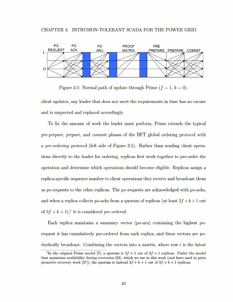
Fi g ur e 3. 1: N or m al p at h of u p d at e t hr o u g h Pri m e ( f = 1, k = 0).
cli e nt u p d at es, a n y l e a d er t h at d o es n ot m e et t h e r e q uir e m e nts i n ti m e h as n o e x c us e
a n d is s us p e ct e d a n d r e pl a c e d a c c or di n gl y.
T o fi x t h e a m o u nt of w or k t h e l e a d er m ust p erf or m, Pri m e e xt e n ds t h e t y pi c al
p r e- p r e p a r e , p r e p a r e , a n d c o m mit p h as es of t h e B F T gl o b al or d eri n g pr ot o c ol wit h
a p r e- o r d e ri n g pr ot o c ol (l eft si d e of Fi g ur e 3. 1). R at h er t h a n s e n di n g cli e nt o p er a-
ti o ns dir e ctl y t o t h e l e a d er f or or d eri n g, r e pli c as first w or k t o g et h er t o pr e- or d er t h e
o p er ati o n a n d d et er mi n e w hi c h o p er ati o ns s h o ul d b e c o m e eli gi bl e. R e pli c as assi g n a
r e pli c a-s p e ci fi c s e q u e n c e n u m b er t o cli e nt o p er ati o ns t h e y r e c ei v e a n d br o a d c ast t h e m
as p o-r e q u ests t o t h e ot h er r e pli c as. T h e p o-r e q u ests ar e a c k n o wl e d g e d wit h p o- a c ks,
a n d w h e n a r e pli c a c oll e cts p o- a c ks fr o m a q u or u m of r e pli c as ( at l e ast 2 f + k + 1 o ut
of 3 f + k + 1), 1 it is c o nsi d er e d p r e- o r d e r e d .
E a c h r e pli c a m ai nt ai ns a s u m m ar y v e ct or ( p o- ar u) c o nt ai ni n g t h e hi g h est p o-
r e q u est it h as c u m ul ati v el y pr e- or d er e d fr o m e a c h r e pli c a, a n d t h es e v e ct ors ar e p e-
ri o di c all y br o a d c ast. C o m bi ni n g t h e v e ct ors i nt o a m atri x, w h er e r o w i is t h e l at est
1 I n t h e o ri gi n al P ri m e m o d el [ 7], a q u or u m i s 2 f + 1 o ut of 3 f + 1 r e pli c a s. U n d er t h e m o d elt h at m ai nt ai n s a v ail a bilit y d u ri n g r e c o v eri e s [ 3 3], w hi c h w e u s e i n t hi s w or k ( a n d h a v e u s e d i n p ri orp r o a cti v e r e c o v er y w or k [ 3 7]), t h e q u or u m i s i n st e a d 2 f + k + 1 o ut of 3 f + k + 1 r e pli c a s.
4 5
CHAPTER 3. INTRUSION-TOLERANT SCADA FOR THE POWER GRID
Figure 3.2: Example of Prime’s ordering matrix. Row i is the latest signed summaryvector (po-aru) from replica i. Sorting each column j and taking the 2f + k + 1th
highest value indicates the requests from j that have been cumulatively pre-orderedby a quorum and are ready to be ordered.
vector from the ith replica, indicates which po-requests are eligible for ordering and
execution. Specifically, sorting column j and taking the 2f +k+1th highest sequence
number (i.e., at least 2f + k + 1 vectors show this value or higher) indicates that all
po-requests from j up through and including this sequence are ready to be ordered.
Figure 3.2 shows an example.
When summary vectors form a matrix indicating new progress (i.e., at least one
new po-request is eligible in this matrix compared to the previous one), the new
matrix is sent to the leader as a proof-matrix message. Upon receiving a proof-
matrix showing new progress, the leader simply has to reflect the most up-to-date
matrix in a pre-prepare message at the next time interval. Since these matrices are
self-contained proofs containing signed vectors, a correct leader can always send the
pre-prepare fast enough (barring network connectivity issues) to meet the timing
challenges of the non-leader replicas, even if the leader has yet to receive or pre-order
46
CHAPTER 3. INTRUSION-TOLERANT SCADA FOR THE POWER GRID
the po-requests itself. Once a valid pre-prepare is sent, the replicas run the standard
BFT prepare and commit phases (right side of Figure 3.1) to bind the pre-prepare
content and execute the updates in agreed order.
Each pre-prepare message essentially orders client updates in waves: the difference
between the matrix in pre-prepare i and the matrix in pre-prepare i − 1 indicates a
new set of po-requests from each replica that should be ordered and executed. The
total order is obtained by applying each replica’s new set (which may be empty for
some replicas) in ascending order by replica ID: all new po-requests from replica 1
are applied, then all new po-requests from replica 2, and so on, though replica n.
3.1.2.2 Proactive Recovery Protocol
We next describe the proactive recovery protocol for Prime that supports an
ephemeral approach to maintaining state. We discuss several requirements for a cor-
rect proactive recovery protocol, identify challenges introduced by the original Prime
protocol in meeting some of these requirements, and describe the key changes made
to Prime and overall strategies to address these challenges.
Proactive Recovery Requirements
• Recovering application and replication-protocol state
Before a recovering replica can rejoin the system, it must first ensure that it has
a consistent copy of the state. Depending on the circumstances, this replica’s state
47
CHAPTER 3. INTRUSION-TOLERANT SCADA FOR THE POWER GRID
may be entirely consistent, may be incorrect or missing if the replica was compro-
mised prior to recovery, may be out of date if the system progressed since the replica
went down for recovery, or even may be nonexistent by design if the system uses
an ephemeral approach to maintain state. By working with the other replicas in the
system, the recovering replica can identify whether its state is inconsistent and, if nec-
essary, obtain a correct and current copy of the application and replication-protocol
state. Application state is specific to the application, and in this case is the latest
set of RTU and PLC updates for the SCADA system. Replication-protocol state is
information used by the intrusion-tolerant replication protocol (in this case, Prime)
to order updates and maintain consistency.
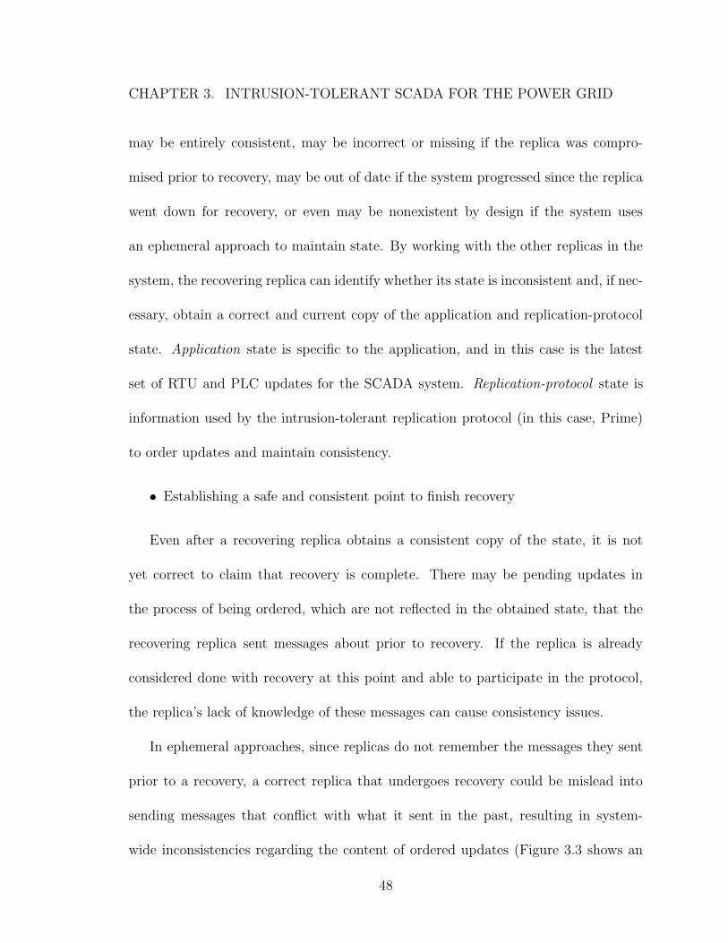
• Establishing a safe and consistent point to finish recovery
Even after a recovering replica obtains a consistent copy of the state, it is not
yet correct to claim that recovery is complete. There may be pending updates in
the process of being ordered, which are not reflected in the obtained state, that the
recovering replica sent messages about prior to recovery. If the replica is already
considered done with recovery at this point and able to participate in the protocol,
the replica’s lack of knowledge of these messages can cause consistency issues.
In ephemeral approaches, since replicas do not remember the messages they sent
prior to a recovery, a correct replica that undergoes recovery could be mislead into
sending messages that conflict with what it sent in the past, resulting in system-
wide inconsistencies regarding the content of ordered updates (Figure 3.3 shows an
48
CHAPTER 3. INTRUSION-TOLERANT SCADA FOR THE POWER GRID
Figure 3.3: Example of inconsistencies that can arise with proactive recoveries in anephemeral approach. In the first step, the red compromised replica assigns message mto sequence number x and orders it with 2f +k+1 replicas (quorum) on one side of apartition. In the second step, one of the original replicas undergoes proactive recoveryand comes back into a different network partition. If the compromised replica nowassignsm′ to x, it will be ordered by these 2f+k+1 replicas, creating an inconsistencyin the ordering regarding the content of message x.
example). In persistent approaches, replicas remember what they sent (eliminating
inconsistency issues), but now a compromised replica that is recovered may be working
with malicious state (e.g., a message log); the replica can only be considered correct
once its potentially-malicious state is no longer relevant to currently ordered updates.
Therefore, a recovering replica must work with the rest of the system to clearly identify
a consistent point in the global ordering at which it can safely complete recovery and
rejoin the system.
49
CHAPTER 3. INTRUSION-TOLERANT SCADA FOR THE POWER GRID
• Resetting data structures to allow previously malicious replicas to rejoin as
correct replicas
Although proactive recovery cleanses compromises from a replica once it is reju-
venated, care must be taken to ensure that while the replica was compromised, it
was not able to block future instantiations of that replica from correctly rejoining
the system after recovering. If such an attack is possible, compromised replicas could
be made permanently unavailable (i.e., unable to help the system make progress),
undermining the benefits and defenses that proactive recovery should provide.
To prevent such attacks, the data structures at both the recovering replica and
the other peer replicas in the system may need to be reset in such a way to remove
the effects of the prior malicious actions. For example, if the compromised replica
was previously added to a blacklist by the other correct replicas, it should be taken
off once recovery is complete to be allowed to participate again. As another example,
if a compromised replica exhausts some sequence number space or contributes a mal-
formed share to a data structure maintained in a distributed manner, the sequence
numbers or share may need to be rolled back or refreshed to enable the recovered
replica’s new messages to validate and be accepted.
Note that this requirement is not solely the responsibility of the recovery protocol,
but also a design criterion that the intrusion-tolerant replication system must consider
in order to provide a solution that supports proactive recovery.
50
CHAPTER 3. INTRUSION-TOLERANT SCADA FOR THE POWER GRID
Proactive Recovery Challenges for Prime
Recovering the application state of the SCADA system and the replication pro-
tocol state of Prime is relatively straightforward. Since we are using an ephemeral
approach, the replica undergoing recovery has no local copy of the state to work with,
and instead must rely on its peers to recover the state. Under the 3f +2k+1 model,
the recovering replica is considered part of the k recovering replicas until it finishes
its recovery, and it is therefore guaranteed to be able to communicate with at least
a quorum (2f + k + 1) of correct replicas to collect (and validate) an up-to-date and
correct version of the state.
However, establishing a safe and consistent point to complete the recovery process
is challenging in Prime when using an ephemeral approach, compared to more tradi-
tional intrusion-tolerant replication protocols (e.g., PBFT [4]). Traditional protocols
use a single global sequence number space to order updates, employing a high water-
mark (upper bound) on the range of sequence numbers concurrently being assigned to
updates. Even with no persistent message log, a recovering replica in these protocols
can simply wait to rejoin the system until a full high watermark number of sequence
numbers have been assigned since starting its recovery. This method guarantees that
the recovering replica will not send messages that are inconsistent with any message
it may have sent (and forgot about) prior to recovery.
In Prime, we cannot use this exact approach, due to the pre-ordering protocol that
fixes the workload of the leader and helps provide bounded delay. In addition to a
51
CHAPTER 3. INTRUSION-TOLERANT SCADA FOR THE POWER GRID
global sequence number space, each replica in Prime manages its own replica-specific
sliding window of sequence numbers that get assigned (and acknowledged) in the
pre-ordering protocol. In order to prevent a recovering replica from sending an incon-
sistent message, both the global sequence number space and the individually-managed
pre-order sequence number spaces must be advanced by a full high watermark. How-
ever, since some of the replicas may be compromised, there is no simple way to force
all replicas to advance their respective window.
Beyond this issue, Prime also uses several distributed data structures that must be
adjusted to safely remove the effects of a previously compromised replica and allow
the recovered replica to once again participate. The most sensitive data structure
is the monotonically-increasing matrix that appears in global ordinals (Figure 3.2
above), where each replica continually contributes a vector to this matrix to order
updates. For this matrix, keeping the contributed vector as is from the replica’s prior
instantiation is unsafe, since it may represent an impossible state (e.g., too far ahead
in the future) that no correct replica could reach. In addition, rolling back the vector
to a previously-known correct state is unsafe because it may result in the matrix indi-
cating backwards progress, violating the monotonically-increasing behavior. We need
a strategy that allows the recovering replica to continue participating in the ordering
protocol without breaking the guarantees or expectations of the Prime protocol.
52
CHAPTER 3. INTRUSION-TOLERANT SCADA FOR THE POWER GRID
Key Strategies and Modifications to Prime to Support Recovery
We create an ephemeral proactive recovery solution for Prime that addresses these
challenges by leveraging a replica-specific monotonically-increasing incarnation num-
ber that is incremented when a replica undergoes proactive recovery. Replicas include
their current incarnation number in the header of every Prime protocol message to
identity which instantiation the replica was in when it sent a message.
In addition, we augment several message types (i.e., po-acks, prepares, and com-
mits), which combine to form different certificates related to the ordering protocol, to
include a vector of the currently accepted incarnations of each replica in the system.
By enforcing that these message types have matching incarnation vectors to form a
certificate, we can prevent two conflicting ordinals with the same sequence number
but different content from being ordered due to a replica recovery (e.g., the scenario
presented in Figure 3.3). We elaborate more on this point next in the high-level
description of the recovery process.
High-Level Recovery Process. Each time a replica starts up (e.g., due to a
proactive recovery), it uses its Trusted Platform Module (TPM) to generate a new
public-private session key pair (since the previous pair may have been compromised)
and a random number. The random number is used, along with the Prime bitcode
(intermediate representation) and MultiCompiler [49] stored in read-only memory, to
generate a new diverse variant of Prime. In addition, the TPM is used to obtain a
monotonically-increasing number that serves as the incarnation for this instantiation.
53
CHAPTER 3. INTRUSION-TOLERANT SCADA FOR THE POWER GRID
After startup, a recovering replica is not allowed to participate in the normal
ordering protocol until it finishes the recovery process. This consists of the recovering
replica communicating with at least a quorum (2f + k+ 1) of distinct replicas in the
system to accomplish three main tasks: get its new incarnation accepted, obtain the
latest Prime protocol state, and collect pending (not yet ordered) updates that it may
have sent messages (acknowledgements) about prior to going down for recovery.
First, a recovering replica sends its peers a message with its new incarnation
to indicate its intent to perform a recovery. Correct replicas rate limit how often
each replica can proactively recover (to prevent compromised replicas from repeatedly
recovering to consume resources), and when a correct replica receives a new (higher)
incarnation from a replica that is allowed to recover, it sends an acknowledgement.
The acknowledgment is a promise that the correct replica will not accept any older
incarnation for the recovering replica going forward.
Upon collecting acknowledgements from a quorum of its peers, the recovering
replica forms and disseminates a certificate that proves its new incarnation is sup-
ported, and correct replicas that receive this certificate accept the new incarnation
for the recovering replica. In addition, correct replicas discard any collected po-acks,
prepares, or commits that do not yet form a complete certificate, since the vector of
accepted incarnations has just changed, and they resend their own local copy of each
such discarded message with the updated vector.
54
CHAPTER 3. INTRUSION-TOLERANT SCADA FOR THE POWER GRID
Next, correct replicas send their latest global ordinal certificates to the recovering
replica, which prove that the system has progressed up through the specified ordinal.
These certificates enable the recovering replica to obtain the necessary Prime protocol
state to begin processing messages, including the view (current leader), global and
replica-specific sequence numbers, and session keys of each replica.
Lastly, correct replicas send the pending updates (po-requests from the pre-ordering
phase) and pending global ordinals (pre-prepares) that they know about to the re-
covering replica.2 Since at least a quorum of replicas transfer their knowledge, the
recovering replica is guaranteed to learn about any update that at least one replica
in the system could have collected a certificate for, even if not currently connected.
Any partially ordered update that is not known by at least one correct replica in this
quorum cannot have completed a certificate (and thus cannot have been pre-ordered
or ordered) using the recovering replica’s previous incarnation, and the discarding and
reissuing of incomplete certificate parts (po-acks, prepares, and commits as mentioned
above) ensures that only a single non-conflicting certificate using the new incarnation
is possible going forward.
Once the replica finishes the tasks above, it is safe to finish recovery, but the replica
must establish a consistent point to rejoin the system. To achieve this, the replica
submits a special first update to be ordered solely by its peers; the recovering replica
is not permitted to help order its first special update. The global ordinal which
2Note that the number of potentially pending po-requests and pre-prepares is bounded due to ahigh watermark enforced on both the global sequence number space and the replica-specific sequencenumber space that limits the number of concurrently pending messages.
55
CHAPTER 3. INTRUSION-TOLERANT SCADA FOR THE POWER GRID
contains this update marks the synchronization point at which the replica finishes
recovery and its new incarnation is installed. When the recovering replica executes
this ordinal, it signals the SCADA master to perform an application-specific state
transfer (discussed in Section3.1.3 below) and resumes the normal Prime protocol.
Note that this is the point at which a replica that was previously compromised is
considered correct again.
Resetting Data Structures. The last modifications to Prime alter specific
data structures to ensure that a recovering replica can correctly rejoin the system
and participate in the ordering protocol, even if it was previously compromised. In
particular, we modify the replica-specific sequence number space (used for originating
po-requests) to now use (current incarnation, sequence number) tuples. After a
recovery, replicas restart their specific sequence number space from sequence 1 (with
their new incarnation) to counteract any potentially malicious behavior of a previously
compromised incarnation (e.g., gaps or inconsistencies created in their replica-specific
window).
As a result, the matrix used in the global ordering protocol is modified to use these
tuples as the entries in the vectors (see Figure 3.4). For example, a vector from replica
i with tuple (x,y) in column j indicates that replica i has cumulatively acknowledged
po-requests 1 through y (inclusive) originated by replica j in incarnation x.
With the introduction of the tuples in the vectors, it is now possible for more
than one incarnation to be present when sorting a column in the matrix. Therefore,
56
CHAPTER 3. INTRUSION-TOLERANT SCADA FOR THE POWER GRID
Figure 3.4: Example of the new Prime ordering matrix supporting proactive recovery.Each vector now contains a tuple (incarnation, sequence) for each other replica’s po-requests. Sorting each column j and taking the 2f + k + 1th highest value from thesame incarnation quorum indicates the requests from j that have been pre-orderedby a quorum. If no such quorum exists, the last executed value is used.
we alter the sorting strategy and introduce an additional last executed vector that
continually keeps track of the highest po-request from each replica that has been
made eligible for execution. For a given column j, if at least a quorum of entries have
matching incarnations, we sort just these entries and take the 2f + k + 1th highest
po-request as being made eligible for execution from j, updating the last executed
vector if progress was made. If no such quorum exists, which can legitimately occur
in the middle of a recovery, this particular matrix is inconclusive with respect to j;
we carry over the previous value from the last executed vector and consider it as a
no-op. Figure 3.4 shows an example of both cases.
Summary. We have described an ephemeral proactive recovery approach specif-
ically tailored for Prime that correctly restores a copy of the state, establishes a safe
57
CHAPTER 3. INTRUSION-TOLERANT SCADA FOR THE POWER GRID
and consistent point for the recovering replica to rejoin the system, and ensures that
compromised replicas cannot block future instantiations from participating in the
Prime protocol. The recovery protocol operates within the 3f + 2k + 1 replication
model to maintain overall system availability and timeliness as long as no more than
k replicas are simultaneously undergoing recovery and no more than f replicas are
simultaneously compromised.
3.1.3 Prime and SCADA Master Interaction
In our replication model, replicas are composed of both the SCADA master and its
associated Prime daemon. The SCADA master handles the SCADA system-specific
functionality and maintains the SCADA application state, and the Prime daemon
provides an intrusion-tolerant ordering service to deliver a totally ordered stream of
updates to the master. Despite these separate responsibilities, it is the interaction
between these two components that combine to produce a complete SCADA master
replica that is capable of operating correctly in spite of network connectivity issues,
across crashes and proactive recoveries, and in the presence of compromised peer
replicas.
Normal System Operation. As we described above in Section 3.1.1, the
SCADA masters forward all received updates from the HMIs and RTUs/PLCs (i.e.,
all inputs) to their Prime daemons for ordering. As the updates are ordered by Prime,
each Prime daemon delivers a contiguous stream of ordered updates to its SCADA
58
CHAPTER 3. INTRUSION-TOLERANT SCADA FOR THE POWER GRID
master, producing a consistent view of the system at each correct SCADA master
replica.
After applying an update, the SCADA master may need to generate a response.
Since each correct SCADA master processes updates in the same order, each one will
also generate the same response message in the same order. Therefore, rather than
needing to perform another ordering to sequence the response message, each SCADA
master can simply reuse the ordinal number that Prime assigned to the original
incoming update by assigning it to the response message. HMIs and RTUs/PLCs
that receive these responses can apply them according to this order and will be able
to collect enough matching messages from the SCADA masters, as is required by the
intrusion-tolerant communication library (see Section 3.1.5).
Note that this optimization is meaningful due to the differences between SCADA
systems and the general kinds of applications that intrusion-tolerant systems have
supported in the past. Traditionally, intrusion-tolerant replication systems considered
update latency as the time between a client introducing an update and that client
getting the response back for that update. But for SCADA systems, that is not
enough; the relevant end-to-end latency includes introducing the original update,
delivering that update, generating a new message in response, and then delivering
this response to the relevant client. Therefore, by eliminating the need to perform a
second intrusion-tolerant ordering phase (i.e., Prime’s Byzantine agreement protocol)
59
CHAPTER 3. INTRUSION-TOLERANT SCADA FOR THE POWER GRID
on the response messages, we reduce the overall end-to-end latency of the SCADA
system updates.
Seamless Catchup. As long as a SCADAmaster replica stays connected with the
working quorum of replicas, it receives all SCADA system updates and its copy of the
state remains consistent and up to date. However, there may be network connectivity
issues, e.g., short bursts of network loss, that cause a replica to miss messages and
fall behind for a short amount of time. In this case, we can use a seamless catchup
mechanism, with the help of other replicas in the system, to recover and deliver all
of the updates that were missed in order. The seamless catchup essentially masks
the short-lived connectivity issue altogether, since there is effectively no difference
between the replica that originally fell behind and other correct replicas.
In our system, the seamless catchup mechanism is managed by Prime. Each Prime
daemon maintains a catchup history of ordered updates that can be retransmitted on
demand to other replicas in the case that they fall behind. If a replica misses some
messages, its Prime daemon will discover that it is behind in the global ordering
ordering protocol and request to be caught up via one of the more up-to-date Prime
daemons. With only short connectivity issues, the out-of-date Prime daemon should
be within the catchup history of another Prime daemon, and the out-of-date Prime
is simply resent the ordered updates it is missing from this history. These ordered
updates include a certificate proving their validity and can be delivered in the correct
order to the SCADA master as they are received. As a result, from the point of
60
CHAPTER 3. INTRUSION-TOLERANT SCADA FOR THE POWER GRID
view of the SCADA master process, every update in the ordering stream was received
contiguously and the SCADA system state remains consistent.
Jump with State Transfer. In more severe network connectivity scenarios, a
replica may experience a network partition for an extended (albeit still temporary)
amount of time. As a result, once it reconnects, the replica may be too far behind
the catchup history of any correct replica in the system to be helped with seamless
catchup. In this case, the Prime daemon will be able to resynchronize at the repli-
cation protocol level by jumping ahead, but the SCADA master will inevitably miss
out on applying some of the updates in the ordering stream; in order to become con-
sistent again, the SCADA master will need to collect a fresh copy of the state via
state transfer. Due to the relatively small size and latest-update-wins nature of the
SCADA application state, this jump with state transfer approach is both feasible and
simple.
The jump with state transfer approach is implemented using a combination of
Prime and SCADA master functionality. When a Prime daemon discovers that it is
too far behind to be helped by means of normal catchup, it requests to be jumped
ahead in the global ordering and waits to receive a valid jump certificate from one of
the up-to-date replicas. This certificate provides the out-of-date Prime daemon with
everything it needs to become current and able to participate at the specified point
in the global ordering protocol.
61
CHAPTER 3. INTRUSION-TOLERANT SCADA FOR THE POWER GRID
While this jump brings the Prime daemon up to date at the replication-protocol
level, the SCADA application state stored at the SCADA master is still potentially
stale because the ordered updates that Prime jumped over were not delivered. Since
these skipped updates cannot be delivered at this point, the SCADA master needs
a state transfer of the application state to become up to date. Due to the presence
of potentially compromised SCADA masters, receiving a single copy of the state is
not guaranteed to be correct. The out-of-date SCADA master needs to obtain f + 1
matching copies of the state to be considered correct, but this requires that the state
be sent at a consistent agreed-upon point from the perspective of correct SCADA
masters.
To achieve this, after a Prime daemon jumps, it will submit, on behalf of its
SCADA master, a special state-transfer update that is ordered by the normal Prime
protocol. When the out-of-date SCADA master processes the state-transfer update
for itself, it prepares to collect copies of the state from its peers; and when other
SCADA masters process the update, they send their copy of the application state
at that point to the target SCADA master. By appearing in the global ordering
stream, this state-transfer update provides a synchronization point to enable correct
SCADA masters to send identical copies of their application state, ensuring that the
out-of-date master can collect the required f + 1 matching copies. Once the state is
collected and adopted, the SCADA master resumes normal operation, processing the
62
CHAPTER 3. INTRUSION-TOLERANT SCADA FOR THE POWER GRID
contiguous stream of updates from its Prime daemon, including ones that may have
been queued during the state collection process.
Proactive Recovery. Restoring a SCADA master’s application state after a
proactive recovery is quite similar to the jump with state transfer case. From the
Prime daemon’s point of view, it must first go through the entire proactive recovery
protocol (as described above in Section 3.1.2) to safely rejoin at the replication-
protocol level. But once this is complete, the Prime daemon submits the same state-
transfer request on behalf of its SCADA master to bring the application state up to
date. From the SCADA master’s point of view, it sees a gap in the ordering stream
and adopts the state collected at the state-transfer update synchronization point;
there is no additional recovery-related work that is necessary in this case.
General Crash Resilience. Beyond network connectivity issues and proactive
recoveries that affect the entire SCADA master replica, there may be scenarios in
which only the SCADA master or Prime daemon restart. If only the SCADA master
restarts, it will expect to receive ordered updates from Prime starting at sequence “1”,
but the Prime daemon may be further along in the global ordering protocol. In this
case, since it just started, the SCADAmaster creates a state-transfer update of its own
and gives the update to its Prime daemon in order to get a current copy of the state
transferred. If only the Prime daemon restarts, this is viewed as a proactive recovery
at the Prime protocol level. During this time, the SCADA master is effectively
63
CHAPTER 3. INTRUSION-TOLERANT SCADA FOR THE POWER GRID
partitioned from its peers, and once Prime finishes recovering, the SCADA master is
transferred the current application state.
Putting it All Together. We described several interactions between the SCADA
master and its associated Prime daemon that are tailored specifically for SCADA
systems. By combining these different interactions, we have an efficient and resilient
SCADA master replica that is capable of operating correctly in spite of network
connectivity issues, across crashes and proactive recoveries, and in the presence of
compromised peer replicas.
Threat Model Note: Shared-Fate Model. As far as compromised replicas
are concerned, the SCADA master and Prime daemon operate under a shared-fate
model, where if either (or both) components are compromised, the entire replica is
considered compromised. This view is accounted for in our model (which considers
compromises as the entire replica being malicious) and is further supported by the
fact that each SCADA master only forwards new updates to and receives ordered
updates from its own Prime daemon.
3.1.4 RTU/PLC Proxy
The RTU/PLC proxy is a system component that plays a vital role in our intrusion-
tolerant SCADA system architecture. The RTU/PLC proxy sits in-between the RTUs
and PLCs in the field sites (e.g., power substations) and the SCADA masters in the
control center, and takes responsibility for polling the RTUs and PLCs. As a re-
64
CHAPTER 3. INTRUSION-TOLERANT SCADA FOR THE POWER GRID
sult, we are able to design our SCADA master to be event-driven to fit the natural
communication model of intrusion-tolerant replication, while maintaining backwards
compatibility with existing RTUs and PLCs that expect to be polled on a regular
basis.
The RTU/PLC proxy polls the RTUs and PLCs and collects their current state
using one of the appropriate SCADA communication protocols that each RTU or
PLC is already equipped to speak; examples of these SCADA protocols include open
industry standards such as Modbus or DNP3, or popular proprietary protocols such
as Siemens S3. When the RTU/PLC proxy detects a change in the state collected
from the RTUs and PLCs, it sends an update to the replicated SCADA master that is
ordered and executed using the intrusion-tolerant replication engine. The proxies also
send periodic status updates to the SCADA master even if no change has occurred,
but this interval may be relatively long (e.g. on the order of a second or more).
This event-driven approach allows the SCADA system to scale to many RTUs
and PLCs, as the intrusion-tolerant replication engine does not need to process each
individual poll (which may occur frequently, e.g. at 100ms intervals). This load
reduction is important for an intrusion-tolerant system, as processing each update
is relatively expensive: the replicas must all agree on and order the update, which
involves exchanging several rounds of messages between the replicas over a (potentially
wide-area) network.
65
CHAPTER 3. INTRUSION-TOLERANT SCADA FOR THE POWER GRID
Moreover, the RTU/PLC proxy can batch status updates from all the RTUs and
PLCs in its substation, further reducing the number of distinct updates the SCADA
masters must process. To achieve scalability without requiring RTUs and PLCs to be
connected to the network, a hierarchical approach can be used, in which each RTU
or PLC is directly connected (via cable) to a simple “bump-in-the-wire” proxy, and
aggregator proxies batch commands from many such proxies. This new design allows
the system to support a large number of RTUs/PLCs, while still maintaining the
required timeliness in the presence of intrusions.
Many of the existing SCADA communication protocols were never designed to
hold up in the presence of attackers. Therefore, our architecture protects the RTUs
and PLCs by limiting the use of their insecure communication protocols (e.g. Modbus
and DNP3) to only the connection between an RTU or PLC and its proxy. To provide
the strongest protection, this connection can be limited to a physical wire (as opposed
to a network). Then, the status updates sent from the proxy to the SCADA masters
(and in fact, all of the other traffic in our SCADA system) use IP over the intrusion-
tolerant network (Section 3.1.6). This network provides confidentiality, integrity, and
authentication, as well as protection against denial of services attacks.
In addition, when installed at a field site, the RTU/PLC proxy can serve as a
secure gateway for all of the RTUs and PLC in that site, providing IP-level protection
mechanisms such as state-of-the-art firewalls. In many cases the RTUs and PLCs
are simple devices that cannot be hardened (on their own) to survive in the wild.
66
CHAPTER 3. INTRUSION-TOLERANT SCADA FOR THE POWER GRID
As our recent experience with a red team shows (Section 3.5.2 below), targeting the
network is a common strategy for attackers, and these additional security mechanisms
significantly improve the resiliency of the RTUs and PLCs. Note, however, that if an
attacker is able to compromise an RTU/PLC proxy, they may be able to compromise
the RTU or PLC from that position, which our threat model does not cover (as noted
in Chapter 2).
Ideally, an RTU/PLC proxy is placed in each field site and is responsible for
managing all the RTUs and PLCs in that site. However, if this is not possible, the
proxies may be placed anywhere between the SCADA master and the field sites,
including in the control center. In fact, for the foreseeable future, many substations
are likely to use non-IP communication and will need to communicate via proxies
located in the control centers.
3.1.5 Intrusion-Tolerant Communication Library
System components that interact with the replicated SCADA master (e.g. the
HMI and RTU/PLC proxies) cannot simply send updates to a single replica. Recall
that under our threat model, the control center may include up to f compromised
replicas and one replica undergoing proactive recovery. Therefore, each update must
be sent to at least f + 2 replicas to ensure that at least one correct replica receives
the update in a timely manner.3
3Alternatively, the update may initially be sent to fewer replicas and re-sent to more replicasafter a timeout only if necessary, but this adds latency.
67
CHAPTER 3. INTRUSION-TOLERANT SCADA FOR THE POWER GRID
To ensure that a message received from the SCADA master replicas is valid,
the HMI or RTU/PLC proxy must know that at least one correct replica reached
agreement on that message. By waiting to receive f + 1 identical copies of the
message from different replicas before considering it valid, a strategy employed by
many intrusion-tolerant replications systems, an HMI or RTU/PLC proxy ensures
that at least one correct replica agrees with the content.
To facilitate communication between the replicated SCADA masters and the HMI
and RTU/PLC proxies, we created an intrusion-tolerant communication library that
takes care of implementing these communication strategies. The HMI and RTU/PLC
proxy use the library, which takes care of sending copies of each update to f + 2
SCADA master replicas and collecting at least f + 1 matching copies of a response
from the SCADA masters before delivering it to the HMI or RTU/PLC proxies.
3.1.6 Spines Intrusion-Tolerant Network
While intrusion-tolerant replication of the SCADA masters (with diversity and
it does not provide resilience to network attacks. If an attacker disrupts the commu-
nication between the control center and the power substations, the SCADA system
loses its ability to monitor and control the power grid, even if all the SCADA masters
are working correctly. Previous work provides timeliness and quality-of-service guar-
antees for SCADA networks [51, 52], but these solutions are not resilient to attacks.
68
CHAPTER 3. INTRUSION-TOLERANT SCADA FOR THE POWER GRID
Therefore, a resilient networking solution is essential for a complete intrusion-tolerant
SCADA system.
Our intrusion-tolerant SCADA system uses the Spines overlay messaging frame-
work [22], which provides the ability to deploy an intrusion-tolerant network [23].
Spines uses an overlay approach to overcome attacks and compromises in the under-
lying networks: overlay sites are connected with redundancy, forcing an attacker to
successfully attack many links in the underlying networks to disrupt communication
to a single site (Section 4.4.1 presents a full description of this resilient architecture).
In addition, Spines provides confidentiality, integrity, and authentication of all
traffic on the overlay. System administrators define the set of authorized overlay
nodes (which in practice is small, on the order of tens of nodes) as well as the overlay
topology. Overlay nodes are given this information, along with the public key of
each of authorized node, to perform the various cryptographic functionalities. How-
ever, cryptographic authentication is not sufficient to protect against an attacker that
compromises an overlay node, thus gaining access to that node’s credentials.
Spines ensures that compromised overlay nodes cannot prevent messages sent by
correct overlay nodes from reaching their destination (provided that some correct path
through the overlay still exists). This is done using redundant dissemination schemes
to ensure that messages reach correct overlay nodes and fairness schemes to ensure
that correct nodes will forward messages from all sources fairly, even if compromised
nodes launch resource consumption attacks.
69
CHAPTER 3. INTRUSION-TOLERANT SCADA FOR THE POWER GRID
Figure 3.5: Intrusion-Tolerant SCADA system architecture for a single control centerdeployment with 6 replicas (f = 1, k = 1).
From the point of view of the SCADA system, each of the system components
(i.e., SCADA master, HMI, and RTU/PLC proxy) connects to a local Spines overlay
node to gain access to the deployed intrusion-tolerant network. All communication
between these components is sent over Spines, providing the needed protection against
network level attacks and compromises.
3.2 Intrusion-Tolerant SCADA
Architecture
Figure 3.5 shows the architecture for a complete intrusion-tolerant SCADA system
deployment using a single control center containing six replicas, which simultaneously
overcomes one compromised replica and one replica undergoing proactive recovery.
70
CHAPTER 3. INTRUSION-TOLERANT SCADA FOR THE POWER GRID
In this architecture, the system continues to make progress as long as four of the
replicas are correct and connected.
The SCADA master is replicated using Prime, and each replica runs a diverse
variant of the software (represented as different colors in Figure 3.5). Periodically,
the replicas are rejuvenated one at time, in a round-robin manner, to remove any
potentially undetected compromises. Rejuvenating replicas follow the proactive re-
covery procedure, which includes generating a new diverse variant of the software
that is different from all past, present, and future variants (with high probability).
We deploy two separate intrusion-tolerant Spines networks to carry the two dif-
ferent types of SCADA system traffic. A coordination network (purple Spines nodes
in Figure 3.5) connects all of the replicas and carries traffic solely between the repli-
cas for the intrusion-tolerant replication protocol; A dissemination network (blue
Spines nodes in Figure 3.5) connects the SCADA master replicas with the HMIs
and RTU/PLC proxies in field sites (substations), carrying the SCADA updates,
responses, and control commands. Note that SCADA master replicas are simultane-
ously connected on both of these intrusion-tolerant networks.
Normal System Operation. SCADA system updates are generated by the
HMI and RTU/PLC proxies: the HMI sends an update when a human operator
enters a command (e.g., via mouse click), and the RTU/PLC proxies send updates
when new status updates are collected from the RTUs and PLCs. These updates
are sent over the dissemination (blue) Spines network to f + 2 replicas in the control
71
CHAPTER 3. INTRUSION-TOLERANT SCADA FOR THE POWER GRID
center. Updates received at the SCADA master replicas are ordered by Prime on the
coordination (purple) Spines network and then executed (in order) by the SCADA
masters.
If an update triggers a response from the SCADA master replicas, the response is
signed by each correct replica and sent over the dissemination (blue) network to the
relevant HMI or RTU/PLC proxy. When an HMI or RTU/PLC proxy receives f + 1
copies of a response message from different replicas with matching content, it knows
that the response is valid and came from at least one correct SCADA master, and it
applies the response in the correct order.
3.3 Implementation Considerations
The intrusion-tolerant SCADA system presented above, along with several other
additional components and considerations discussed next, are combined and imple-
mented as the Spire [34] system. Spire is meant to provide a complete top-to-bottom
intrusion-tolerant SCADA solution for the power grid, serving as the realization of
a SCADA system with protection against attacks at both the system and network
level that can meet the timeliness requirements of the power grid. Spire is available
as open source and is deployable in a number of different architectures and configu-
rations, including the ones presented in this thesis, depending on the guarantees and
resiliency needed by power grid operators.
72
CHAPTER 3. INTRUSION-TOLERANT SCADA FOR THE POWER GRID
Figure 3.6: Example of an HMI created for a small power grid installation using ourpvbrowser-based solution.
pvbrowser-based HMI. The HMI solution provided in Spire is a derivative
of the HMI that comes with the open-source pvbrowser SCADA software suite [53].
pvbrowser is a mature SCADA solution that has been used to manage a real power grid
deployment in Romania spanning 10,000 square kilometers with 50 power switches.
However, pvbrowser also shares the same server-driven polling model as conventional
SCADA systems, making it complex to integrate intrusion-tolerant replication and
motivating the need to create our own solution from scratch.
Nonetheless, the HMI and Modbus protocol implementation (described next) of
pvbrowser are high-quality, useful components to leverage and incorporate. The
pvbrowser HMI provides the system operator with the ability to define a graphi-
cal user interface (GUI) (e.g., including custom images, buttons, and knobs) that
supports the target SCADA scenario. Figure 3.6 shows an example HMI created us-
73
CHAPTER 3. INTRUSION-TOLERANT SCADA FOR THE POWER GRID
ing our solution. We re-architected the HMI to to communicate with the rest of our
intrusion-tolerant SCADA system via the intrusion-tolerant communication library,
while maintaining the existing GUI development functionality. The HMI communi-
cates only through Spines and does not accept out-of-band communication.
SCADA Communication Protocol Support. The RTU/PLC proxy collects
the latest status updates from RTUs and PLCs in the field sites by speaking the
appropriate SCADA communication protocols. Today, there are a large number of
different protocols in use, and simultaneously supporting all of them from the start
is a difficult task (especially considering that many are proprietary). Therefore, the
RTU/PLC proxy was created to initially support two of the widely-used open stan-
dard SCADA protocols, Modbus and DNP3, to be able speak with as many PLCs
and RTUs as possible up front. Over time, the proxy can be improved to add support
for additional SCADA protocols as needed. To support Modbus and DNP3, we lever-
age the open-source implementations available from pvbrowser and OpenDNP3 [54]
respectively.
For each supported SCADA communication protocol, the RTU/PLC proxy spawns
a process that manages all of its connections to the RTUs and PLCs it is responsible
for that speak that protocol. For example, a RTU/PLC proxy that is responsible
for polling three Modbus and two DNP3 PLCs spawns both the Modbus and DNP3
management processes, whereas a proxy that speaks to four DNP3 RTUs only spawns
the DNP3 management process. Upon startup, each RTU/PLC proxy reads a con-
74
CHAPTER 3. INTRUSION-TOLERANT SCADA FOR THE POWER GRID
figuration file to determine which RTU/PLCs it is responsible for, connects using the
appropriate SCADA protocol, and collects updates at the specified polling interval.
Communication Library. Each SCADA system component (i.e., SCADA mas-
ter, HMI, and RTU/PLC proxy) spawns a thread to manage the intrusion-tolerant
communication library functionality discussed in Section 3.1.5. This logically sepa-
rates the SCADA-related functionality from the intrusion-tolerant behavior, enabling
a simpler system design: rather than requiring large design changes to the SCADA
components to operate in the intrusion-tolerant architecture, only minimal changes
are needed to integrate each component with the associated separate thread.
Figure 3.7: Spire SCADA master replica, containing both the SCADA master andthe paired Prime daemon. The numbered arrows show the path of an update throughthe system originating from an HMI or RTU/PLC proxy.
75
CHAPTER 3. INTRUSION-TOLERANT SCADA FOR THE POWER GRID
Replica Architecture. Figure 3.7 shows the process and thread architecture
of the Spire SCADA master replica. Each replica is composed of a SCADA master
process (gray box) and an associated Prime daemon process (green box). The SCADA
master process contains several threads to facilitate the communication between the
SCADA master and Prime. New updates coming from the HMIs or RTU/PLC proxies
are received by the inject thread at the SCADA master and forwarded locally to
Prime. If too many local updates are currently pending ordering, the Prime daemon
blocks the inject thread until it has room to accept more.
Once updates are ordered by Prime, they are delivered to the SCADA master at
the intrusion-tolerant reliable channel thread, which is the main thread that manages
the intrusion-tolerant communication library functionality. New updates are passed to
the SCADA master thread, which actually processes and applies the SCADA updates
to the state and generates responses. These responses are passed back to the main
intrusion-tolerant thread, where they are signed and sent to the relevant HMI or
RTU/PLC proxy.
PLC Emulation. In power grid deployments, the RTU/PLC proxies connect
with real RTUs and PLCs in power substations. However, when designing and testing
new SCADA system scenarios, it is helpful to be able to quickly create and emulate
PLCs that are accurate representations of how the physical devices will behave. To
emulate PLCs, Spire uses OpenPLC [55], an open source project that provides an open
76
CHAPTER 3. INTRUSION-TOLERANT SCADA FOR THE POWER GRID
and fully functional PLC that can be programmed and deployed both in software and
on hardware devices.
Security Considerations. While the intrusion-tolerant system is able to over-
come compromises, it is also important to protect the different components in the
architecture with good security practices; these considerations effectively create a
strong perimeter that serves as a first line of defense. Some examples of such security
considerations include keeping the operating systems patched with the latest security
updates and installing strict firewalls. As our recent red-team experience shows, tar-
geting the network is a common strategy for attackers, as it does not require domain
or application-specific knowledge to disrupt service, and building a secure perimeter
is quite valuable for a SCADA system.
3.4 Bounded Delay with Proactive
Recoveries
As discussed in Section 2.3, Spire guarantees bounded delay. However, as noted
in [37], the original analysis of Prime’s bounded delay guarantee in [7] did not account
for proactive recovery. The original analysis relied on the fact that eventually a leader
will be elected that will never be suspected; however, when proactive recovery is used,
even a correct leader will eventually be taken down for rejuvenation and lose its role
as leader.
77
CHAPTER 3. INTRUSION-TOLERANT SCADA FOR THE POWER GRID
Because Prime’s view change protocol completes within a bounded amount of
time, Spire can still support bounded delay, as long as we can bound the number of
view changes required to settle on a new correct leader.4 In the worst case, when a
correct leader is taken down for recovery, we may simultaneously have f compromised
replicas that are the next f replicas in the round-robin order to be tried as the new
leader. In this case, the number of required view changes is f + 1.
3.5 Evaluation
We deploy Spire in the single control center architecture described in Section 3.2
and evaluate its ability to support the timeliness needs of the power grid in that
setting, both in normal conditions and while under attack. We then describe our
recent participation in a red-team exercise in a single control center environment,
where an experienced hacker team attacked both a commercial SCADA system setup
according to best practices and our Spire system.
3.5.1 Single Control Center Deployment
Spire was deployed in a single control center using six total SCADAmaster replicas
(Figure 3.5 above), which simultaneously overcomes one compromised replica and one
4As originally specified, Prime does not guarantee that every correct replica can act as the leader:the f slowest correct replicas may be suspected and removed from their role. However, in the single-control-center architecture, we can impose a floor on the acceptable turnaround time in the LANenvironment such that the leader is never required to provide a faster turnaround time than theslowest correct replica is capable of.
78
CHAPTER 3. INTRUSION-TOLERANT SCADA FOR THE POWER GRID
Figure 3.8: Update latency histogram over 1-hour deployment in a single controlcenter with 6 replicas (f = 1, k = 1).
replica undergoing proactive recovery. In this experiment, we setup a mock control
center using our development lab. Each SCADA master replica (both the SCADA
master and its Prime daemon) was placed on a separate machine on a local area
network (LAN). Spire monitored and controlled ten emulated power substations that
introduced updates to the SCADA system via RTU/PLC proxies at the rate of one
update per second. All communication was done over either the dissemination or
coordination Spines intrusion-tolerant networks that were deployed.
Normal Case Operation. We first evaluate Spire’s ability to support the time-
liness requirements of the power grid in a single control center in normal operating
conditions, without attacks. We conducted a test over a one-hour period, during
which each update submitted by an RTU/PLC proxy was ordered by Prime and de-
livered to the SCADA masters, which then generated a response message that was
79
CHAPTER 3. INTRUSION-TOLERANT SCADA FOR THE POWER GRID
Figure 3.9: Update latencies over 1-hour deployment in a single control center with6 replicas (f = 1, k = 1).
sent back to the relevant proxy. For each update, we calculated the latency from
the time the update was submitted to the time the response was received, which
effectively characterizes the roundtrip latency of the SCADA system.
Figure 3.8 summarizes the update latencies observed over the one-hour period in a
histogram. The average and median latencies were both 26.7ms (milliseconds), with
99.8% of the updates having latencies between 13.1ms and 39.4ms. The latency for
each update over the one-hour period is plotted in Figure 3.9. All 36,000 updates had
latencies below 100ms, which is the optimistic latency target to achieve to support
the real-time nature of the power grid.
These measured latencies are consistent with what we expect from Spire de-
ployed in a single control center setup. There are largely two sources of latency
that contribute to the overall roundtrip times: the time to send messages between
80
CHAPTER 3. INTRUSION-TOLERANT SCADA FOR THE POWER GRID
the RTU/PLC proxies and SCADA masters in the control center, and the time for
the Prime daemons to order each update with the Byzantine agreement protocol. In
our setup, it takes between 5ms and 7ms to send a message between the proxies and
SCADA masters, which is representative of the fact that the RTUs and PLCs are
not necessarily co-located with the control center, but rather located some distance
away in field sites.5 For Prime, even though replicas are all connected by a LAN,
the normal ordering protocol uses batching and regularly-scheduled ordering inter-
vals, based on a system parameter (e.g., every 20ms in our setup), to fix and reduce
the workload of the leader (as described in Section 3.1.2.1). Therefore, depending
on when each update is introduced and received at the leader, the time to order the
update in Prime can vary within the parameter range (with an average of half the
range, or 10ms, per update). This behavior can been seen in the fixed-size band of
latencies in both Figure 3.8 and Figure 3.9.
Performance Under Attack. To evaluate Spire’s performance under attack,
we launched targeted attacks designed to test the system’s ability to withstand a
proactive recovery, a compromised replica, and the combination of the two. We
present the results of these attacks in Figure 3.10. Proactive recovery of a non-leader
replica (e.g. of replica 2 at 00:30) has no effect on the system’s performance. Proactive
recovery of the current leader (e.g. of replica 1 at 01:30) leads to a view change in
5This 5-7ms latency between field sites and the control center is a parameter of our system setupthat we estimated to be accurate for typical power grid installations in North America spanninga few hundred miles. In practice, this latency will differ for each installation depending on thecorresponding deployment characteristics. But in all cases, this latency contributes a constantamount of time (at the edges) to the overall roundtrip latency Spire provides.
81
CHAPTER 3. INTRUSION-TOLERANT SCADA FOR THE POWER GRID
Figure 3.10: Latency in the presence of intrusions and proactive recoveries in a singlecontrol center deployment with 6 replicas (f = 1, k = 1).
Prime, which causes a brief latency spike (with one update exceeding 100ms in this
case).
While in general a compromised replica can perform arbitrary actions, we demon-
strate Spire’s resilience to two illustrative types of attacks. In the first attack, the
leader generally acts correctly, to avoid being suspected and replaced, but attempts
to increase the latency of updates. In Figure 3.10, from 02:00 to 03:40, the leader
gradually adds delay, increasing update latencies in the end to about 50ms; however,
when it tries to increase the delay beyond this, it is suspected and a Prime view
change occurs. In the second attack, the leader attempts to send a pre-prepare mes-
sage containing incorrect values to violate the total ordering, but this is immediately
detected, and the leader is removed in a view change at 04:15.
82
CHAPTER 3. INTRUSION-TOLERANT SCADA FOR THE POWER GRID
The last attack shows the combination of an intrusion with a proactive recovery.
At 04:45, the replica that would become the next leader (if there was a view change)
starts proactive recovery. Then at 05:00, the current leader, which is compromised,
acts maliciously and is detected and removed, but since the next leader is undergoing
proactive recovery, it causes two view changes to occur before settling on a correct
leader.
Overall, this evaluation demonstrates Spire’s effectiveness in providing a intrusion-
tolerant SCADA solution for a single control center deployment.
3.5.2 Red-Team Exercise
In April 2017, we participated in a red-team exercise as part the DoD Environ-
mental Security Technology Certification Program (ESTCP), in which an experienced
hacker team from Sandia National Labs attacked both a commercial SCADA system
set up according to best practices and our Spire intrusion-tolerant SCADA system.
The goal of the experiment was to assess the extent to which existing SCADA systems
using best practices can stand up to sophisticated cyber attacks, as well as determine
(and demonstrate) the potential benefits of a fault and intrusion-tolerant SCADA
system (i.e. Spire).
Figure 3.11 shows the network diagram of the single control center in which both
SCADA systems were deployed to monitor and control the mini power grid. The
network has two main parts: the enterprise network (top of the Figure 3.11) and
83
CHAPTER 3. INTRUSION-TOLERANT SCADA FOR THE POWER GRID
the operational network (bottom of the figure). The enterprise network connects the
non-critical power grid components that reside within the site, such as a mail server
or file server. In contrast, the operational network connects the critical SCADA
system components, including the SCADA masters, HMIs, and RTUs/PLCs. The
operational network is separated from the enterprise network via a strict firewall that
should prevent any malicious and undesired network traffic from reaching the critical
SCADA components. Figure 3.11 shows the two SCADA systems deployed side-by-
side in the operational network: the commercial SCADA system is on the right, and
Spire is on the left.
Part 1: Attacking Commercial SCADA set up with Best Practices. The
red team was first given an access point within the enterprise network and asked to
try and affect the commercial SCADA system in the operations network. Within just
a few hours of attacking the system from outside the operations network firewall, the
red team completely took over the PLC controlling the mini power grid set up in the
exercise by launching a man-in-the-middle attack between the SCADA master and the
PLC. With direct access to the PLC, they were able to make changes to the registers
and settings, and were even able upload their own malicious configuration file to affect
the PLC more persistently, requiring manual fixes by the system operator. The red
team was then placed directly inside the operations network, on the same network
switch as the commercial SCADA system. From this point, they were also able to
84
CHAPTER 3. INTRUSION-TOLERANT SCADA FOR THE POWER GRID
Figure 3.11: Network diagram of DoD ESTCP Project experiment hosted at thePacific Northwest National Laboratory in April 2017, which evaluated a SCADAsystem set up according to best practices (right side of Operational Network) andthe Spire intrusion-tolerant SCADA system (left side of Operational Network) in ared-team exercise conducted by an experienced hacker team.
85
CHAPTER 3. INTRUSION-TOLERANT SCADA FOR THE POWER GRID
take over the connection between the HMI and SCADA master of the commercial
system via a similar man-in-the-middle attack.
Part 2: Attacking Spire. The red team was then tasked to launch the same
attacks against the Spire intrusion-tolerant SCADA system. Over the course of two
days of attacks, both from the enterprise network and from within the operations
network, the red team was not able to cause any disruption. From the enterprise
network, the red team could not even see any of Spire’s traffic, let alone affect any of
the normal system behavior.
Once placed in the operations network, the red team launched a variety of attacks,
including ARP poisoning, sending IPv6 traffic (that should not normally be present),
spoofing IP addresses of Spire machines, and sending bursts of traffic to Spire compo-
nents to attempt denial of service attacks. None of these attacks were effective in any
way due to the secure network setup with cloud expertise that prevented ARP poi-
soning attacks and enforced strict firewall rules,6 the authentication and encryption
of all traffic by Spire’s intrusion-tolerant network, and the architecture that enforced
that the PLC only communicate through the secure RTU/PLC proxy.
On the last day, the red team was given access to a machine running one of Spire’s
SCADA master replicas and Spines nodes on both the dissemination and coordination
networks. This was effectively testing Spire’s ability to overcome a compromised
replica inside the system. Over the course of the day, the red team was gradually
6We were fortunate to receive help from friends at Spread Concepts LLC [56] and LTN GlobalCommunications [57] that have cloud expertise in hardening machines and securely setting up net-works to safely exist on the Internet.
86
CHAPTER 3. INTRUSION-TOLERANT SCADA FOR THE POWER GRID
given increased access on the machine: they started with user-level access, then they
were given root-level access, and finally they were given the source code with a pointer
to the corresponding files and functions that are responsible for the intrusion-tolerant
functionality. From this position inside the system, the red team launched denial of
service attacks, but were unsuccessful due to the fairness enforced by the intrusion-
tolerant protocols. In addition, they tried to attack the Spines intrusion-tolerant
network implementation, but were unable to affect any of the other Spines nodes in
the system or affect the guarantees.
Lessons Learned. There are several key takeaways from the experiment. First,
current SCADA systems deployed in the approximately 3,200 U.S. electric utilities
are vulnerable, even if set up according to best practices. With more SCADA systems
moving to use IP, along with other attack vectors in even air-gapped systems (e.g.,
Stuxnet [16]), attackers will likely be able to gain presence inside a utility’s network,
and exploitations of this vulnerability are a real threat (and in some cases, may be
inevitable).
Second, the red team largely focused their efforts on network-level attacks, even
from a compromised node inside the system. From an attacker’s point of view, this
makes sense; if generic network attacks can take down the system, there is no need to
invest resources in developing sophisticated domain-specific attacks. This observation
reinforces the need to address the expanded threat model we consider in this work that
simultaneously considers network attacks and system compromises. The experiment
87
CHAPTER 3. INTRUSION-TOLERANT SCADA FOR THE POWER GRID
showed that successfully protecting the network requires both a secure network setup
and intrusion-tolerant network protocols.
Finally, there is a significant difference between the protection provided by con-
ventional SCADA systems and that provided by our Spire intrusion-tolerant SCADA
system. We are not claiming that Spire is completely immune to attacks; however,
the results show that the same red team that was able to obliterate existing SCADA
systems in just a couple of hours was unable to affect the intrusion-tolerant SCADA
system in any way over three days. Spire’s intrusion tolerance kept the SCADA sys-
tem working in spite of a compromised replica, and the security design principles
kept normally unprotected components secure. Most notably, the RTU/PLC proxy
protected the vulnerable PLC against the red team’s numerous attempts to gain
access.
88
Chapter 4
Network-Attack-Resilient
Intrusion-Tolerant SCADA
While deploying our intrusion-tolerant SCADA system in the single-control-center
architecture presented in Chapter 3 provides significant resiliency benefits compared
with conventional SCADA systems, the architecture does not completely address the
types of network attacks that we know exist today. Specifically, recent sophisticated
DDoS attacks [20, 21] can target and isolate a site from the network at a time of
the attacker’s choosing. With only a single control center site managing the grid, the
attacker can disconnect this control center and disrupt its ability to communicate with
the field substations, causing system-wide downtime of grid monitoring and control.
To address these network attacks, clearly more than one site is needed; and in fact,
state-of-the-art SCADA systems deployed today actually use two control centers: a
Figure 4.1: Illustration of specific SCADA system configurations’ ability to supportthe threat model we consider, including all combinations of a replica being unavailabledue to proactive recovery, a site disconnection due to network attack or failure, andan intrusion (SCADA master compromise).
x replicas in the first control center, y replicas in a second control center, and so on.
Each configuration shown in Figure 4.1 is discussed in Section 4.1.2, 4.1.3, or 4.1.4.
Below, we explain the meaning of the colored cells in Figure 4.1, which is also shown
in the key below the table.
A green cell represents a fully operational system with performance guarantees
under attack. In this case, the system is guaranteed to process any update within the
Table 4.1: SCADA system configurations using 2 control centers and 1, 2, or 3 datacenters to simultaneously tolerate a proactive recovery, disconnected site, and 1, 2,or 3 intrusions
k = max
(f + 3,
⌈3f + S + 1
S − 2
⌉)
As before, after obtaining a value for k, we calculate the total number of required
replicas, based on the requirement n ≥ 3f +2k+1. To distribute the replicas among
the sites, f + 2 replicas must first be placed in each control center. The remaining
replicas must then be distributed such that no single site has more than k−1 replicas,
which can be achieved by distributing replicas as evenly as possible across the sites.
Table 4.1 presents the minimal number of replicas required to tolerate one, two,
or three intrusions while simultaneously supporting a single proactive recovery and a
single disconnected site with two control centers and one, two, or three data centers
(for a total of three, four, or five sites). In the table, the first two numbers in each
cell represent the number of replicas in each of the two control centers, while the
remaining numbers represent the number of replicas in each data center.
As Table 4.1 shows, configurations with more sites require fewer total replicas,
because losing any one site has less impact on the system. This presents a trade-off
between the cost of additional sites, compared with the cost of additional replicas and
guaranteed to get that update to a correct replica, as that entire control center may
currently be disconnected due to a network attack. Therefore, each update must be
sent to at least f +2 replicas in each control center to ensure that at least one correct
control-center replica receives the update in a timely manner.1
Threshold Cryptography. With the original strategy, a HMI or RTU/PLC
proxy must wait to receive f + 1 matching copies of a response message before it
can ensure that the message is valid and from at least one correct SCADA master.
However, considering our complete threat model and the new architectures where only
control-center replicas can directly communicate with HMIs and RTU/PLC proxies,
it may not be possible at all times to receive f + 1 matching copies from control-
center replicas. For example, consider the “3+3+3+3” configuration during which one
control center is disconnected and the other control center has both a compromised
replica and a replica undergoing proactive recovery. In this case, only one control
center is available to send a copy of the response, but the HMIs and RTU/PLC
proxies require f + 1 = 2 matching copies.
Therefore, we instead use an (f + 1, n) threshold signature scheme [58], where
at least f + 1 out of n total shares are required to create a valid signature. All
replicas, both in control centers and data centers, create their respective share for
each response message and send it to the control-center replicas, which each combine
f + 1 shares with matching content into a single RSA signature on the response
1As stated earlier, the update may alternatively be sent initially to fewer replicas and re-sent tomore replicas after a timeout, only if necessary, at the cost of additional latency.
then depending on the number of total sites, we augment the control centers with one,
two, or three commodity data centers, each equipped with their own overlay node.
We leverage commodity data centers because they are well-provisioned: ISPs invest
in such locations by laying independent fiber connections between them. By selecting
data centers that are relatively close to the control centers, we can use the underlying
network topology (based on available ISP backbone maps) to create short overlay
links between the sites such that Internet routing between these overlay neighbors is
predictable.2 The resulting overlay topology spans three to five total sites and cov-
ers the geographic footprint of the designated power grid with a resilient networking
infrastructure. The field sites connect to both control centers for redundancy, either
via secure client connections to the control center overlay nodes or by hosting their
own overlay node that is part of the resilient topology.
The resilient network architecture makes it significantly harder to isolate a target
site using an attack like Coremelt or Crossfire; a successful attack must simultaneously
affect multiple overlay links (enough to cut the site from the rest of the network
at the overlay level), attacking each such overlay link on multiple ISPs (enough to
cut any combination of ISPs available on that overlay link). SCADA systems are
key infrastructure components that are likely to be targeted by nation-state-level
attackers willing to invest considerable resources to disrupt the power grid, and it
is possible for a site to be disconnected due to attack. However, we believe that
2In addition, having data centers close to control centers reduces the normal-case latency ofSCADA updates, which now must go through several rounds of wide-area network messaging in themultiple-site architectures to complete the intrusion-tolerant ordering protocol.
Figure 4.6: Updated Spire SCADA master replica for multiple-site architectures,with threshold-signed response messages. The numbered arrows show the path of anupdate through the system originating from an HMI or RTU/PLC proxy.
to the additional threshold-signature phase in the normal update path (introduced in
Section 4.2).
4.5 Bounded Delay with Sophisticated
Network Attacks
In Section 3.4, we expanded the original bounded delay guarantees from Prime
to account for proactive recoveries, in addition to the potential presence of up to
f compromised replicas. Next, we expand bounded delay further to also include a
potentially disconnected site due to a network attack, by incorporating the effects of
the disconnected site on the number of view changes required to settle on a correct
leader.3
In the worst case, when a correct leader is taken down for recovery, we may simul-
taneously have f compromised replicas and one disconnected or failed site. Because
Prime chooses leaders in round-robin order, we leverage replica striping (Section 4.4.2
above) to prevent repeatedly trying to switch to a new leader in the same failed site.
For example, in configuration “3+3+3+3”, settling on a correct leader may require
executing f + 2 = 3 view changes (where the first view change tries to elect a replica
from the disconnected site, the second tries to elect the compromised replica, and the
third successfully elects a correct replica).
In general, the worst-case number of view changes required is: f + 2 +⌊f+1S−1
⌋,
assuming striping of replicas across sites. This accounts for the proactive recovery, f
compromises, and disconnected site, as well as the fact that when the total number
of sites S is less than or equal f+2, we can cycle through all S sites and try to elect a
leader in the disconnected site multiple times. Note that the worst case occurs when
the leader is in the site that becomes disconnected, the next leader is recovering, and
the next f leaders are compromised.
3As originally specified, Prime does not guarantee that every correct replica can act as the leader:the f slowest replicas may be suspected and removed from their role. However, when the geographiclocations of the replicas and the normal-case latencies between them are known, this is easily fixed byimposing a floor on the acceptable turnaround time, so that the leader is never required to provide afaster turnaround time than the slowest correct replica is capable of (while not subject to a networkattack).
6 + 6+ 6 51.4 ms 100.00 100.00 39.5 ms 40.6 ms 51.3 ms 63.8 ms 68.8 ms3 + 3+ 3+ 3 54.7 ms 100.00 100.00 43.1 ms 44.2 ms 54.7 ms 65.4 ms 67.1 ms3 + 3+ 2+ 2+ 2 56.4 ms 100.00 100.00 44.5 ms 45.8 ms 56.3 ms 67.3 ms 69.5 ms5 + 5+ 5+ 4 57.4 ms 100.00 100.00 45.4 ms 46.6 ms 57.4 ms 68.8 ms 71.8 ms6 + 6+ 6+ 6 64.8 ms 99.9111 99.9667 50.4 ms 52.2 ms 64.5 ms 82.7 ms 97.7 ms
Table 4.3: SCADA configuration performance on LAN with emulated latencies be-tween sites for 36000 updates over 1 hour. Px represents the xth percentile.
Overall, this evaluation demonstrates Spire’s practicality in supporting the ex-
tended threat model in a real-life situation.
4.6.2 Feasibility of Multiple-Intrusion Support
While we consider configuration “3+3+3+3” the most practical configuration sup-
porting one intrusion, we present a range of configuration options in this chapter and
aim to support multiple intrusions. Therefore, we assess the feasibility of other con-
figurations in a local-area environment with emulated latencies between the machines
configured to match those observed between the geographic sites in the wide-area
evaluation in Section 4.6.1.
For each of the evaluated configurations, we run the same experiments that were
performed on the wide-area “3+3+3+3” configuration, including both normal case
evaluation and performance under attack. The results comparing the normal case
behavior across all configuration evaluations are shown in Tables 4.2 and 4.3.
redesigning expensive parts of the replication protocol, or exchanging some expensive
cryptographic mechanisms for more feasible ones.
We note that while it is always better to support more simultaneous intrusions,
the theoretical model in [37] shows that most of the benefit of proactive recovery can
be obtained by supporting two intrusions, rather than one. Supporting more than
two intrusions provides additional benefits, but with diminishing returns. Therefore,
the ability to support two simultaneous intrusions in our demanding threat model
(including network attacks) is a meaningful milestone.
143
Chapter 5
Resilient SCADA as a Service
As our experience with the red team shows (Section 3.5.2), conventional SCADA
systems currently deployed in electric utility installations, even if setup according
to best practices, are vulnerable to knowledgeable attackers. Successfully protect-
ing critical SCADA systems requires cloud-like expertise in network and machine
configuration, state-of-the-art intrusion-tolerance techniques, and the use of multiple
active control sites, potentially using commodity data centers for feasibility (Chap-
ter 4), to create Internet-ready environments that can withstand successful attacks
and compromises.
However, the scarcity of this expertise, combined with the current state of the
heavily-regulated power grid ecosystem, which does not list intrusion tolerance as
a top priority on the regulators’ checklists, makes it unlikely that many individual
power companies will be able to independently deploy SCADA systems capable of
144
CHAPTER 5. RESILIENT SCADA AS A SERVICE
overcoming sophisticated attacks in the near future. Moreover, an unfortunate real-
ization is that even if a handful of utility companies were able to deploy the multi-site
intrusion-tolerant solution we are proposing, there could be consequences due to the
interconnected nature of the power grid (e.g., the Eastern and Western Interconnec-
tions of North America, or the Continental Synchronous Area of Europe) [60]. While
these large interconnects were designed to provide economies of scale and improve
resiliency to benign failures, compromised installations in one area of the grid may
be able to cause cascading failures of other well-protected installations due to the
effects of malicious reporting on the tightly-synchronized grid. Switching from these
interconnects to smaller independent deployments would take significant financial
investment over several years [60].
Effective solutions for the current power grid model should provide a coordinated
defense that brings the necessary resiliency expertise to many individual utility in-
stallations simultaneously, creating a natural fit for a service provider solution. Mi-
grating SCADA systems to cloud-like settings can lower utility companies’ costs,
increase scalability, and offer new features and resilient services that would otherwise
be unobtainable. A few large cloud SCADA providers with specialized knowledge
of state-of-the-art security and intrusion-tolerance principles could manage SCADA
systems for many individual utility companies that make up the interconnected grids.
Despite these potential benefits, using a cloud SCADA provider raises security
and confidentiality issues. A utility company may want to keep certain sensitive in-
145
CHAPTER 5. RESILIENT SCADA AS A SERVICE
formation about its SCADA system private and avoid revealing those details to the
cloud provider, for example, due to concerns about cloud data breaches or unau-
thorized access by other users of the cloud. Such sensitive information may include
the locations and IP addresses (or other communication/access methods) of field sites
and RTUs/PLCs, and may potentially include other types of data as well (e.g., status
updates or commands specific to the grid).
In this chapter, we present a vision for leveraging the benefits of the cloud to
manage SCADA systems without revealing sensitive information by providing only
an abstract representation of that data to the cloud. Rather than storing physical
addresses in the cloud, utility companies can assign logical addresses to their field sites
and RTUs/PLCs. The cloud’s abstract state only includes these logical addresses, and
only the specific utility company’s sites can translate the logical addresses back into
physical addresses to accurately display the state of the physical system and issue
control commands to the correct RTUs/PLCs in the field sites. Next, we present
several different SCADA system architectures using a cloud provider setup that aim
to preserve a utility company’s privacy.
146
CHAPTER 5. RESILIENT SCADA AS A SERVICE
5.1 Privacy-Preserving Cloud-Based
SCADA Architectures
In the first architecture, the SCADA system includes SCADA master replicas
distributed across both utility company control centers and one or more cloud data
centers. Figure 5.1 shows this architecture for the “3+3+3+3” configuration pre-
sented in Chapter 4, using two utility company control centers and two cloud data
centers. The system uses an intrusion-tolerant replication protocol to agree on ab-
stract operations.1 These operations use the logical addresses of the actual endpoints
(i.e., HMIs and RTU/PLC proxies) to keep the physical addresses private from the
cloud. As long as one correct SCADA master is available in one of the utility com-
pany control centers and enough total correct and connected replicas are available
across the system, the system will be able to reach agreement on the operations, and
the correct control center SCADA master will be able to translate from abstract to
physical state and issue commands to the remote units in the field sites.
A cheaper alternative to the configuration in Figure 5.1 is to use virtualization to
run multiple SCADA master replicas on a single physical machine. Virtualization can
be employed in the control centers sites, data center sites, or both. It is also possible
for a single site to use a combination of physical and virtual replicas. Note that while
1While we present cloud-based architectures using intrusion-tolerant replication protocols, simi-lar architectures are deployable for benign fault-tolerant replication protocols (which require feweroverall replicas to tolerate f non-malicious faults) that also want to preserve privacy.
147
CHAPTER 5. RESILIENT SCADA AS A SERVICE
Figure 5.1: SCADA architecture for 3+3+3+3 configuration (using two cloud datacenters) with only abstract state stored in the cloud SCADA master replicas.
virtualization reduces cost, it does require that utility company operators additionally
trust that the hypervisor underlying the virtual machines on a single physical machine
remains correct; if the hypervisor is compromised, then all virtual machines on that
physical machine are also compromised, which may affect system availability or even
break the assumptions if now more than f replicas are compromised.
In the network-attack-resilient intrusion-tolerant SCADA architectures presented
in Chapter 4, RTU/PLC proxies must receive a threshold-signed proof that a suf-
ficient number of replicas agreed on the abstract operation, and must be able to
verify that the translation from abstract to physical state was done correctly to avoid
the problem of a compromised SCADA master performing incorrect translation. If
148
CHAPTER 5. RESILIENT SCADA AS A SERVICE
only the physical addresses are abstracted, the RTU/PLC proxies can know their
own logical address to determine whether the commands they receive were correctly
translated and were actually intended for them. More generally, the proxies can know
the translation function between abstract and physical state to make sure that the
translation is correct.
In another architecture, SCADA master replicas can run only in cloud data cen-
ters. This can be useful, for example, if a utility company does not want to run its
own SCADA master replicas, e.g., due to cost or capability constraints, or to simplify
management. One approach is to have one or more utility company control sites (not
necessarily containing replicas) that translate abstract state to physical state to issue
commands to the relevant RTUs and PLCs via the proxies.
Note that if there is only one utility company control site, it becomes a single point
of failure, since it must be available to translate and issue commands and is vulnerable
to a sophisticated network attack (as explained in Chapter 4). Nonetheless, for utility
companies that did not have more than one control site available to begin with, this
architecture is likely still beneficial.
If a utility company does not have multiple control sites available to deploy re-
dundant SCADA masters or translation units, it can avoid having a single control
site as a single point of failure by moving the translation closer to the RTUs/PLCs in
the field sites at the cost of revealing slightly more information to the cloud provider.
Each field site can have its RTU/PLC proxy perform the translation. Cloud sites will
149
CHAPTER 5. RESILIENT SCADA AS A SERVICE
need to know the physical address of the relevant proxies to directly communicate
with them, but do no need to know physical information about the rest of the system
(including the actual RTUs and PLCs contained within the field sites, behind the
proxy).
In addition to using logical addresses, utility companies may consider using ab-
stract representations of other aspects of the system state and operations. In this
case, the utility company SCADA masters or translators would not only convert be-
tween physical addresses and logical addresses, but also convert between real system
state and operations and abstract data. Cloud data center SCADA masters would use
functions that can take abstract updates as input and generate the correct abstract
responses without knowing what the update or response really means. These func-
tions may be similar in nature to homomorphic encryption techniques (e.g., [61,62]);
such techniques allow computation to be performed on encrypted data, generating
an encrypted result that, once decrypted, matches the result of the operation as if it
had been performed on the plaintext.
150
Chapter 6
Conclusion
As key components of critical infrastructure, SCADA systems are likely to be
targeted by nation-state-level attackers willing to invest considerable resources to
disrupt the power grid. However, SCADA systems were never designed to withstand
malicious attacks, and as more SCADA systems become connected to the Internet for
the cost and scalability benefits, they are exposed to hostile environments in which
vulnerabilities can be exploited. State-of-the-art intrusion tolerance techniques can
considerably improve the resilience of SCADA systems, enabling them to remain
correct and available even in the presence of successful compromises.
In this thesis, we presented the first intrusion-tolerant SCADA system that simul-
taneously addresses system compromises and network attacks. Our SCADA system
is designed from the ground up to support intrusion-tolerant replication that meets
the strict needs of SCADA for the power grid. The design is implemented in the
151
CHAPTER 6. CONCLUSION
Spire intrusion-tolerant SCADA system [34] and is publicly available as open source
(www.dsn.jhu.edu/spire). A deployment of Spire in a mini power grid setup suc-
cessfully withstood a red-team experiment by an experienced hacker team, and a
wide-area evaluation of Spire showed that it can support the requirements of power
grid control systems under attack.
While our intrusion-tolerant SCADA system addresses a broad threat model that
has not been considered before, it is not a solution to the entire security problem
facing power grids today. The grid is a large and complex system with many moving
parts that are vulnerable to attack. By releasing our work as open source, we hope
to educate the power community about new solutions that are possible and promote
an ecosystem of collaboration among the research community, power companies, and
government. Such an ecosystem can draw on community expertise to develop, test,
and improve new technologies in response to emerging threats, and ultimately lead
to the realization of an intrusion-tolerant power grid.
152
Bibliography
[1] C. W. Ten, C. C. Liu, and G. Manimaran, “Vulnerability assessment of cyberse-
curity for scada systems,” IEEE Transactions on Power Systems, vol. 23, no. 4,
pp. 1836–1846, Nov 2008.
[2] D. J. Kang, J. J. Lee, S. J. Kim, and J. H. Park, “Analysis on cyber threats
to SCADA systems,” in 2009 Transmission Distribution Conference Exposition:
Asia and Pacific, Oct 2009, pp. 1–4.
[3] C. M. Davis and T. J. Overbye, “Confirmation of a Coordinated Attack on the
Ukrainian Power Grid,” SANS Industrial Control Systems Security Blog, 2016.
[4] M. Castro and B. Liskov, “Practical Byzantine fault tolerance and proactive