141
Inverter Inverter i550 Cabinet 0.25 ... 75 kW Project planning | EN

InverterInverter i550 Cabinet 0.25 ... 75 kW
Project planning | EN


ContentsAbout Lenze 4
The 5 phases 4Portfolio overview 5Inverter overview 6
About this document 8Document description 8Notations and conventions 9
Project planning 10Procedure of an inverter configuration process 10
Dimensioning 10Operation in motor and generator mode 13Overcurrent operation 14
Safety instructions 15Application as directed 15Handling 16Residual hazards 17
Control cabinet structure 18Arrangement of components 18Cables 19Earthing concept 19EMC-compliant installation 20
i550 22
Appendix 136Good to know 136
Approvals/directives 136Operating modes of the motor 137Motor control types 138Switching frequencies 140Enclosures 140
Contents
3

About Lenze
The 5 phases
Lenze makes many things easy for you.With our motivated and committed approach, we work together with you to create the bestpossible solution and set your ideas in motion - whether you are looking to optimise an exist-ing machine or develop a new one. We always strive to make things easy and seek perfectiontherein. This is anchored in our thinking, in our services and in every detail of our products.It's as easy as that!
1 Developing ideasAre you looking to build the best machine possible and already have some initial ideas? Thenget these down on paper together with us, starting with small innovative details and stretch-ing all the way to completely new machines. Working together, we will develop an intelligentand sustainable concept that is perfectly aligned with your specific requirements.
2 Drafting conceptsWe see welcome challenges in your machine tasks, supporting you with our comprehensiveexpertise and providing valuable impetus for your innovations. We take a holistic view of theindividual motion and control functions here and draw up consistent, end-to-end drive andautomation solutions for you - keeping everything as easy as possible and as extensive as nec-essary.
3 Implementing solutionsOur easy formula for satisfied customers is to establish an active partnership with fast decisionmaking processes and an individually tailored offer. We have been using this principle to meetthe ever more specialised customer requirements in the field of machine engineering formany years.
4 Manufacturing machinesFunctional diversity in perfect harmony: as one of the few full-range providers in the market,we can provide you with precisely those products that you actually need for any machine task— no more and no less. Our L-force product portfolio a consistent platform for implementingdrive and automation tasks, is invaluable in this regard
5 Ensuring productivityProductivity, reliability and new performance peaks on a daily basis these are our key successfactors for your machine. After delivery, we offer you cleverly devised service concepts toensure continued safe operation. The primary focus here is on technical support, based on theexcellent application expertise of our highly-skilled and knowledgeable after-sales team.
About LenzeThe 5 phases
4

Portfolio overview
Lenze products undergo the most stringent testing in our own laboratory. This allows us toensure that you will receive consistently high quality and a long service life. In addition to this,five logistics centres ensure that the Lenze products you select are available for quick deliveryanywhere across the globe.
As easy as that.
Controllers
Gearboxes
Motors
Visualisation
Inverters
Time and event-controlled motion
Speed and torque-controlled motion
Controlling and visualising events
Automating and visualising machine modules
Logic Control Machine module-Control
Automating and visualising machines
Machine Control
Position-controlled single-axis and multi-axis motion
Mains operation Inverter operation Servo inverter operation
About LenzePortfolio overview
5

Inverter overview
Comparison of i500Inverter i510 i550
Application area Pumps and fans, conveyor, travelling, winding, forming, tool and hoist drives Electrical supply sys-tem
1/N/PE 1/3/PE 3/PE 1/N/PE 1/3/PE 3/PE 3/PEAC 170 ... 264 V AC 170 ... 264 V AC 340 ... 528 V AC 170 ... 264 V AC 170 ... 264 V AC 170 ... 264 V AC 340 ... 528 V
45 ... 65 Hz 45 ... 65 Hz 45 ... 65 Hz 45 ... 65 Hz 45 ... 65 Hz 45 ... 65 Hz 45 ... 65 HzMotor power 0.25 ... 2.2 kW 0.25 ... 2.2 kW 0.37 ... 2.2 kW 0.25 ... 2.2 kW 0.25 ... 2.2 kW 4.0 ... 5.5 kW 0.37 ... 75 kWInverter output cur-rent
1.7 ... 9.6 A 1.7 ... 9.6 A 1.3 ... 5.6 A 1.7 ... 9.6 A 1.7 ... 9.6 A 16.5 ... 23 A 1.3 ... 150 A
Inverter efficiencyclass
IE2 according to EN 50598-2
Max. inverter outputcurrent
150 % at an overload time of 60 s200 % at an overload time of 3 s
RFI filters Integrated not integrated Integrated Integrated not integrated Integrated IntegratedDissipation of regen-erative energy
- - - Brake resistor Brake resistor Brake resistor Brake resistorDC-bus connec-tion
Inverter version Control cabinet Degree of protection IP20 according to EN 60529 Inverter mountingtype
Installation, easy mounting via keyhole suspension
Control connectionsand networks
Basic I/Os Standard-I/O
5 digital inputs - 1 digital output 5 digital inputs - 1 digital output 2 analog inputs - 1 analog output 2 analog inputs - 1 analog output HTL incremental encoder via 2 digital inputs Modbus or CANopen (switchable) Modbus CANopen EtherCAT EtherNet/IP PROFIBUS PROFINET Application I/O 7 digital inputs - 2 digital outputs 2 analog inputs - 2 analog outputs HTL incremental encoder via 2 digital inputsMore connections Relay Relay Connection for PTC or thermal contact External 24 V supplyFunctional safety Without STO (Safe torque off)Approvals CE, RoHS2, UL (for USA and Canada), EAC Interference suppres-sion
Residential areas C1, industrial premises C2
About LenzeInverter overview
6

Function Inverter Available as of firmware versioni510 i550 V1.1 V2.1 V3.0
Motor control V/f characteristic control linear/square-law (VFC plus) V/f characteristic control Midpoint Sensorless vector control (SLVC) Energy saving function (VFCeco) Servo control for asynchronous motors Torque mode Motor functions Flying restart circuit Slip compensation DC braking Oscillation damping Skip frequencies Automatic identification of the motor data Brake energy management Holding brake control Rotational Energy Ride Through (RERT) Speed feedback (HTL encoder) Application functions Process controller Parameter change-over S-shaped ramps for smooth acceleration Motor potentiometer Flexible I/O configuration Access protection Automatic restart Sequencer Position counter Monitoring Short circuit, earth fault Device overload monitoring (I x t) Motor overload monitoring (I2x t)
Mains phase failure, motor phase failure Stalling protection Motor current limit Maximum torque Ultimate motor current Motor speed monitoring Load loss detection Motor temperature monitoring Diagnostics Error history buffer, logbook LED status display Network CANopen Modbus PROFIBUS EtherCAT EtherNet/IP PROFINET Functional safety (optional) STO (Safe torque off)
About LenzeInverter overview
7
About this document
Document descriptionThis document is aimed at all persons who want to project inverters with the described prod-ucts.
The data and information compiled here serve to support you in dimensioning and selectingand preparing the electrical and mechanical installation. You will receive information on prod-uct extensions and accessories.
More informationFor certain tasks, more information is available in additional documents.
Document Contents/topicsCommissioning document Setting and parameterising the invertersMounting Instructions Basic information for the mechanical and electrical installation
• Is supplied with each component."Functional safety" configuration document Information on this (optional) function
Information and tools with regard to the Lenze products can be found on theInternet:http://www.lenze.com à Download
About this documentDocument description
8

Notations and conventionsThis document uses the following conventions to distinguish different types of information:
Numbers Decimal separator Point In general, the decimal point is used.
Example: 1 234.56Warning UL warning UL Are used in English and French. UR warning URText Programs » « Software
Example: »Engineer«, »EASY Starter«Icons Page reference ¶ Reference to another page with additional information
Example: ¶ 16 = see page 16 Documentation reference , Reference to another documentation with additional information
Example: , EDKxxx = see documentation EDKxxx
Layout of the safety instructions
DANGER!This note refers to an imminent danger which, if not avoided, may result in death or seriousinjury.
WARNING!This note refers to a danger which, if not avoided, may result in death or serious injury.
CAUTION!This note refers to a danger which, if not avoided, may result in minor or moderate injury.
NOTICEThis note refers to a danger which, if not avoided, may result in damage to material assets.
About this documentNotations and conventions
9

Project planning
Procedure of an inverter configuration process
Dimensioning
3 methods for dimensioningFast: Selection of the inverter based on the motor data of a 4-pole asynchronous motor.
Detailed: In order to optimise the selection of the inverter and all drive components, it isworth to execute the detailed system dimensioning based on the physical requirements of theapplication. For this purpose, Lenze provides the «Drive Solution Designer» (DSD) design pro-gram.
Manual: The following chapter guides you step by step to the selection of a drive system.
Workflow of a configuration process Define required input variable
Calculate range of adjustment and determine rated point
Determine motor based on the rated data
Define correction factors for the inverter
Determine inverter based on the rated data
Check motor/inverter combination
Determine brake resistance
Final configuration
Define required input variablesOperating mode S1 or S6Max. load torque ML,max Nm
Max. load speed nL,max rpm
Min. load speed nL,min rpm
Site altitude H m Temperature in the control cabinet TU °C
Calculate range of adjustment and determine rated point CalculationSetting range
= L,max
L,min
nV
n
Project planningProcedure of an inverter configuration processDimensioning
10

Setting range Rated point
Motor with integral fan≤ 2.50 (20 - 50 Hz)≤ 4.35 (20 - 87Hz)≤ 6 (20 - 120Hz)
50 Hz87 Hz120 Hz
Motor with blower ≤ 10.0 (5 - 50 Hz)≤ 17.4 (5 - 87Hz)≤ 24 (5 - 120Hz)
50 Hz87 Hz120 Hz
Motor with integral fan(reduced torque)
Determine motor based on the rated data CheckRated torque Operating mode S1 Mrated Nm
³´
L,maxN
H,Mot U,Mot
MM
T T
Operating mode S6 Mrated Nm³
´ ´L,max
NH,Mot U,Mot
MM
2 T T
Rated speed nrated rpm nrated ≥ nL,max
£nL,min
nn
V
NoteRated torque Mrated Nm
→ Rated motor dataRated speed nrated rpm
Rated point at Hz → setting rangePower factor cos ϕ
→ Rated motor dataRated current IN,MOT A
Rated power Prated kW
Correction factor - site altitude TH,MOT → Technical motor data
Correction factor - ambient temperature TU,MOT
Select motor
Correction factors for the inverterSite altitude Amsl H
[m] ≤ 1000 ≤ 2000 ≤ 3000 ≤ 4000
kH,INV 1.00 0.95 0.90 0.85
Temperature in the control cabinet TU
[°C] ≤ 40 ≤ 45 ≤ 50 ≤ 55Switching frequency 2 or 4 kHz kTU,INV
1.00 1.00 0.875 0.750 8 or 16 kHz 1.00 0.875 0.750 0.625
Determine inverter based on the rated data CheckOutput current Continuous operation Iout A Iout ≥ IN,Mot / (kH,INV x kTU,INV)
Overcurrent operation cycle 15 s Iout A Iout ≥ IN,Mot x 2 / (kH,INV x kTU,INV)
Overcurrent operation cycle 180 s Iout A Iout ≥ IN,Mot x 1.5 / (kH,INV x kTU,INV)
Check motor/inverter combination CalculationMotor torque M Nm
( )æ ö= - - j ´ç ÷ç ÷ jè ø
2out,INV 2 N
N,MOT
l MM 1 cos
I cos
Project planningProcedure of an inverter configuration process
Dimensioning
11

CheckOverload capacity of the inverter
£L,maxM1.5
M
Braking operation without additional measuresTo decelerate small masses, the "DC injection brake DCB" function can be parameterised. DC-injection braking enables a quick deceleration of the drive to standstill without the need foran external brake resistor.• A code can be used to select the braking current.• The maximum braking torque to be realised by the DC braking current amounts to approx.
20 ... 30 % of the rated motor torque. It is lower compared to braking action in generatormode with external brake resistor.
• Automatic DC-injection braking (Auto-DCB) improves the starting performance of the motorwhen the operation mode without speed feedback is used.
Braking operation with external brake resistorTo decelerate greater moments of inertia or with a longer operation in generator mode anexternal brake resistor is required. It converts braking energy into heat.
The brake resistor is connected if the DC-bus voltage exceeds the switching threshold. übers-chreitet. This prevents the controller from setting pulse inhibit through the "Overvoltage" faultand the drive from coasting. The external brake resistor serves to control the braking processat any time.
The brake chopper integrated in the controller connects the external brake resistor.
Determine brake resistance Application With active load With passive loadRated power Prated kW
³ ´h ´h ´ 1N max e m
z
tP P
t´h ´h
³ ´max e m 1N
z
P tP
2 t
Thermal capacity Cth kWs ³ ´h ´h ´th max e m 1C P t ´h ´h³ ´max e m
th 1P
C t2
Rated resistance Rrated Ω³
´h ´h
2DC
Nmax e m
UR
P
Active load Can start to move independent of the drive (e.g. unwinder)Passive load Can stop independent of the drive (e.g. horizontal travelling drives, centrifuges, fans)UDC [V] Switching threshold - brake chopper
Pmax [W] Maximum occurring braking power
η e Electrical efficiency
η m Mechanical efficiency
t1 [s] Braking time
tz [s] Cycle time = time between two successive braking processes (t1+ dead time)
Final configurationProduct extensions and accessories can be found here:• Product extensions ^ 77• Accessories ^ 97
Project planningProcedure of an inverter configuration processDimensioning
12

Operation in motor and generator modeThe energy analysis differs between operation in motor mode and generator mode.
During operation in motor mode, the energy flows from the supplying mains via the inverterto the motor which converts electrical energy into mechanical energy (e. g. for lifting a load).
During operation in generator mode, the energy flows back from the motor to the inverter.The motor converts the mechanical energy into electrical energy - it acts as a generator (e. g.when lowering a load).
The drive brakes the load in a controlled manner.
The energy recovery causes a rise in the DC-bus voltage. If this voltage exceeds an upper limit,the output stage of the inverter will be blocked to prevent the device from being destroyed.
The drive coasts until the DC-bus voltage reaches the permissible value range again.
In order that the excessive energy can be dissipated, a brake resistor or a regenerative moduleis required.
Project planningProcedure of an inverter configuration process
Operation in motor and generator mode
13

Overcurrent operationThe inverters can be driven at higher amperages beyond the rated current if the duration ofthis overcurrent operation is time limited.
Two utilisation cycles of 15 s and 180 s are defined. Within these utilisation cycles, an overcur-rent is possible for a certain time if afterwards an accordingly long recovery phase takes place.
Cycle 15 s
During this operation, the inverter may be loaded for 3 s with up to 200 % of the rated currentif afterwards a recovery time of 12 s with max. 75 % of the rated current is observed. A cyclecorresponds to 15 s.
Cycle 180 s
During this operation, the inverter may be loaded for 60 s with up to 150 % of the rated cur-rent if afterwards a recovery time of 120 s with max. 75 % of the rated current is observed. Acycle corresponds to 180 s.
The monitoring of the device utilisation (Ixt) causes the set error response if one of the twoutilisation values exceeds the threshold of 100 %.
The maximum output currents correspond to the switching frequencies and theoverload behaviour of the inverters are given in the rated data.
In case of rotating frequencies < 10 Hz, the time-related overload behaviourmay be reduced.
The graphics shows a cycle. The basic conditions given in the table (graphics field highlightedin grey) have to be complied with in order that the inverter will not be overloaded. Both cyclescan be combined with each other.
t
I [%]
100
T1 T2
0
A
B
Max. output current Max. overload time Max. output current duringthe recovery time
Min. recovery time
A T1 B T2
% s % sCycle 15 s 200 3 75 12Cycle 180 s 150 60 75 120
Project planningProcedure of an inverter configuration processOvercurrent operation
14

Safety instructionsDisregarding the following basic safety measures and safety information may lead to severepersonal injury and damage to property!
Please observe the specific safety information in the other sections!
Application as directed• The product must only be operated under the operating conditions prescribed in this docu-mentation.
• The product meets the protection requirements of 2014/35/EU: Low-Voltage Directive.• The product is not a machine in terms of 2006/42/EC: Machinery Directive.• Commissioning or starting the operation as directed of a machine with the product is notpermitted until it has been ensured that the machine meets the regulations of the EC Direc-tive 2006/42/EC: Machinery Directive; observe EN 60204−1.
• Commissioning or starting the operation as directed is only allowed when there is compli-ance with the EMC Directive 2014/30/EU.
• The harmonised standard EN 61800−5−1 is used for the inverters.• The product is not a household appliance, but is only designed as component for commer-
cial or professional use in terms of EN 61000−3−2.• The product can be used according to the technical data if drive systems have to comply
with categories according to EN 61800−3.
In residential areas, the product may cause EMC interferences. The operator is responsiblefor taking interference suppression measures.
• The product must only be actuated with motors that are suitable for the operation withinverters.• Lenze L-force motors meet the requirements• Exception: m240 motors are designed for mains operation only.
Project planningSafety instructions
Application as directed
15

Handling
Transport, storageObserve the notes regarding transport, storage and correct handling. Ensure proper handlingand avoid mechanical stress. Do not bend any components and do not change any insulationdistances during transport or handling. Do not touch any electronic components and contacts.Inverters contain electrostatically sensitive components which can easily be damaged by inap-propriate handling. Do not damage or destroy any electrical components since thereby yourhealth could be endangered!
InstallationThe technical data and supply conditions can be obtained from the nameplate and the docu-mentation. They must be strictly observed.
The inverters have to be installed and cooled according to the regulations given in the corre-sponding documentation Observe the climatic conditions according to the technical data. Theambient air must not exceed the degree of pollution 2 according to EN 61800−5−1.
Electrical connectionWhen working on live inverters, observe the applicable national regulations for the preventionof accidents.
The electrical installation must be carried out according to the appropriate regulations (e. g.cable cross-sections, fuses, PE connection). Additional information can be obtained from thedocumentation.
This documentation contains information on installation in compliance with EMC (shielding,earthing, filter, and cables). These notes must also be observed for CE-marked inverters. Themanufacturer of the system is responsible for compliance with the limit values demanded byEMC legislation. The inverters must be installed in housings (e. g. control cabinets) to meet thelimit values for radio interferences valid at the site of installation. The housings must enablean EMC-compliant installation. Observe in particular that e. g. the control cabinet doors havea circumferential metal connection to the housing. Reduce housing openings and cutouts to aminimum.
Inverters may cause a DC current in the PE conductor. If a residual current device (RCD) is usedfor protection against direct or indirect contact for an inverter with three-phase supply, only aresidual current device (RCD) of type B is permissible on the supply side of the inverter. If theinverter has a single-phase supply, a residual current device (RCD) of type A is also permissi-ble. Apart from using a residual current device (RCD), other protective measures can be takenas well, e. g. electrical isolation by double or reinforced insulation or isolation from the supplysystem by means of a transformer.
OperationIf necessary, systems including inverters must be equipped with additional monitoring andprotection devices according to the valid safety regulations.
After the inverter has been disconnected from the supply voltage, all live components andpower terminals must not be touched immediately because capacitors can still be charged.Please observe the corresponding stickers on the inverter.
All protection covers and doors must be shut during operation.
You may adapt the inverters to your application by parameter setting within the limits availa-ble. For this, observe the notes in the documentation.
Safety functionsCertain inverter versions support safety functions (e. g. ”safe torque off”, formerly ”safe stand-still”) according to the requirements of the EC Machinery Directive 2006/42/EC. The notes onthe integrated safety provided in this documentation must be observed.
Maintenance and servicingThe inverters do not require any maintenance if the prescribed operating conditions areobserved.
Project planningSafety instructionsHandling
16

DisposalIn accordance with the current provisions, inverters and accessories have to be disposed of bymeans of professional recycling. Inverters contain recyclable raw material such as metal, plas-tics an electronic components.
Residual hazardsEven if notes given are taken into consideration and protective measures are implemented,the occurrence of residual risks cannot be fully prevented.
The user must take the residual hazards mentioned into consideration in the risk assessmentfor his/her machine/system.
If the above is disregarded, this can lead to severe injuries to persons and damage to prop-erty!
Protection of persons
Before working on the inverter, check if no voltage is applied to the power terminals.• Depending on the device, the power terminals X105 remain live for up to 3 ... 20 minutes.• The power terminalsX100 and X105 remain live even when the motor is stopped.
Motor protection
With some settings of the inverter, the connected motor can be overheated.• E. g. by longer operation of self-ventilated motors at low speed.• E. g. by longer operation of the DC-injection brake.
Protection of the machine/system
Drives can reach dangerous overspeeds.• E. g. by setting high output frequencies in connection with motors and machines not suita-
ble for this purpose.• The inverters do not provide protection against such operating conditions. For this purpose,
use additional components.
Switch contactors in the motor cable only if the controller is inhibited.• Switching while the inverter is enabled is only permissible if no monitoring functions areactivated.
MotorIf there is a short circuit of two power transistors, a residual movement of up to 180°/numberof pole pairs can occur at the motor! (For 4-pole motor: residual movement max. 180°/2 =90°).
Parameter set transfer
During the parameter set transfer, control terminals of the inverters can adopt undefinedstates.• Thus, the control terminal of the digital input signals have to be removed before the trans-
fer.• This ensures that the inverter is inhibited. The control terminals are in a defined state.
Project planningSafety instructions
Residual hazards
17

Control cabinet structure
Control cabinet requirements• Protection against electromagnetic interferences• Compliance with the ambient conditions of the installed components
Mounting plate requirements• The mounting plate must be electrically conductive.- Use zinc-coated mounting plates or mounting plates made of V2A.- Varnished mounting plates are unsuitable, even if the varnish is removed from the con-
tact surfaces.• When using several mounting plates, make a conductive connection over a large surface
(e. g. using grounding strips).
Arrangement of components• Division into power and control areas
Fig. 1: Example for the ideal arrangement of components in the control cabinet
Project planningControl cabinet structureArrangement of components
18

CablesRequirements• The cables used must correspond to the requirements at the location (e. g. EN 60204−1,
UL).• The cable cross-section must be dimensioned for the assigned fusing. Observe national and
regional regulations.• You must observe the regulations for minimum cross-sections of PE conductors. The cross-section of the PE conductor must be at least as large as the cross-section of the power con-nections.
Installation inside the control cabinet• Always install cables close to the mounting plate (reference potential), as freely suspended
cables act like aerials.• Use separated cable channels for motor cables and control cables. Do not mix up different
cable types in one cable channel.• Lead the cables to the terminals in a straight line (avoid tangles of cables).• Minimise coupling capacities and coupling inductances by avoiding unnecessary cable
lengths and reserve loops.• Short-circuit unused cores to the reference potential.• Install the cables of a 24 V DC supply (positive and negative cable) close to each other or
twisted over the entire length to avoid loops.
Installation outside the control cabinet• In the case of greater cable lengths, a greater cable distance between the cables is required.• In the case of parallel routing (cable trays) of cables with different types of signals, the
degree of interference can be minimised by using a metallic cable separator or isolatedcable ducts.
Earthing concept• Set up the earthing system with a star topology.• Connect all components (inverters, filters, chokes) to a central earthing point (PE rail).• Comply with the corresponding minimum cross-sections of the cables.• When using several mounting plates, make a conductive connection over a large surface
(e. g. using grounding strips).
Project planningControl cabinet structure
Cables
19

EMC-compliant installationStructure of a CE-typical drive system
The drive system (frequency inverter and drive) corresponds to 2014/30/EU: EMC Directive ifit is installed according to the specifications of the CE-typical drive system.The structure in the control cabinet must support the EMC-compliant installation with shiel-ded cables.• Please use highly conductive shield connections.• Connect the housing with shielding effect to the grounded mounting plate with a surface as
large as possible, e. g. of inverters and RFI filters.• Use central earthing points.
Matching accessories makes effective shielding easier.• Shield sheets• Shield clips/shield clamps• Metallic cable ties
Mains connection, DC supply• Inverters, mains chokes, or mains filters may only be connected to the mains via unshielded
single cores or unshielded cables.• When a line filter is used, shield the cable between mains filter or RFI filter and inverter if its
length exceeds 300 mm. Unshielded cores must be twisted.• In DC-bus operation or DC supply, use shielded cables.- Only certain inverters are provided with this connection facility.
Voltages for the DC-bus operationVoltage on the motor side DC supply Voltage range
VAC VDC VDC
400 565 480 - 0 % ... 622 + 0 %2/PE
480 675 577 - 0 % ... 747 + 0 %
Project planningControl cabinet structureEMC-compliant installation
20

Motor cable• Only use low-capacitance and shielded motor cables with braid made of tinned or nickel-
plated copper.- The overlap rate of the braid must be at least 70 % with an overlap angle of 90 °.- Shields made of steel braids are not suitable.
• Shield the cable for motor temperature monitoring (PTC or thermal contact) and install itseparately from the motor cable.- In Lenze system cables, the cable for brake control is integrated into the motor cable. If
this cable is not required for brake control, it can also be used to connect the motor tem-perature monitoring up to a length of 50 m.
- Only certain inverters are provided with this connection facility.• Connect the shield with a large surface and fix it with metal cable binders or conductive
clamp. The following is suitable for the connection of the shield:- The mounting plate- A central grounding rail- A shield sheet, optional where necessary
• This is optimal:- The motor cable is separated from the mains cables and control cables.- The motor cable only crosses mains cables and control cables at right angles.- The motor cable is not interrupted.
• If the motor cable must be opened all the same (e. g. by chokes, contactors, or terminals):- The unshielded cable ends must not be longer than 100 mm (depending on the cablecross-section).
- Install chokes, contactors, terminals etc. spatially separated from other components (witha minimum distance of 100 mm).
- Install the shield of the motor cable directly before and behind the point of separation tothe mounting plate with a large surface.
• Connect the shield with a large surface to PE in the terminal box of the motor at the motorhousing.- Metal EMC cable glands at the motor terminal box ensure a large surface connection of
the shield with the motor housing.
Control cables• Install the cables so that no induction-sensitive loops arise.• Distance of shield connections of control cables to shield connections of motor cables and
DC cables:- At least 50 mm
• Control cables for analog signals:- Must always be shielded- Connect the shield on one side of the inverter
• Control cables for digital signals:
Cable length< ca. 5 m ca. 5 m ... ca. 30 m > ca. 30 m
Design unshielded option unshielded twisted option always shieldedconnected on both sides
Network cables• Cables and wiring must comply with the specifications and requirements of the used net-
work.- Ensures the reliable operation of the network in typical systems.
Project planningControl cabinet structure
EMC-compliant installation
21
InverterInverter i550 Cabinet 0.25 ... 75 kW
Project planning | EN

InhaltProduct information 26
Product description 26Equipment 27The modular system 28
The concept 28Topologies / network 29Ways of commissioning 30
Functions 31Overview 31Motor control types 31
Features 32Motor setting range 32
The name of the product 34
Technical data 35Standards and operating conditions 35
Conformities/approvals 35Protection of persons and device protection 35EMC data 36Motor connection 36Environmental conditions 36Electrical supply conditions 37
1-phase mains connection 230/240 V 38Rated data 38Fusing and terminal data 40
1/3-phase mains connection 230/240 V 42Rated data 43Fusing and terminal data 45
3-phase mains connection 230/240 V 47Rated data 47Fusing and terminal data 48
3-phase mains connection 400 V 49Rated data 49Fusing and terminal data 54
3-phase mains connection 480 V 59Rated data 59Fusing and terminal data 64
Dimensions 690.25 kW ... 0.37 kW 690.55 kW ... 0.75 kW 701.1 kW ... 2.2 kW 713 kW ... 5.5 kW 727.5 kW ... 11 kW 7315 kW ... 22 kW 7430 kW ... 45 kW 7555 kW ... 75 kW 76
Inhalt
23

Product extensions 77Overview 77I/O extensions 78
Standard-I/O 78Application I/O 79Data of control connections 80
More control connections 83Relay output 83PTC input 84
Networks 85CANopen 85Modbus 87PROFIBUS 89EtherCAT 91EtherNet/IP 92PROFINET 94
Functional safety 96Safety module 96
Accessories 97Overview 97Operation and diagnostics 98
Keypad 98USB module 98WLAN module 99Blanking cover 100Setpoint potentiometer 101
Memory modules 101Memory module copier 101Brake resistors 102Mains chokes 105
1-phase mains connection 230/240 V 1051/3-phase mains connection 230/240 V 1053-phase mains connection 230/240 V 1063-phase mains connection 400 V 1063-phase mains connection 480 V 106
RFI filters / Mains filters 107Sine filter 112Power supply units 113Brake switches 113Mounting 114
Shield mounting kit 114Terminal strips 115
Inhalt
24

Mounting/ installation 116Electrical installation 118
Important notes 118Mains connection 121
1-phase mains connection 230/240 V 1221/3-phase mains connection 230/240 V 1233-phase mains connection 230/240 V 1243-phase mains connection 400 V 1253-phase mains connection 480 V 126
Motor connection 127Switching in the motor cable 127
Connection of motor temperature monitoring 127Brake resistor connection 128Control connections 129
Purchase order 130Notes on ordering 130Order code 131
Inhalt
25
Product information
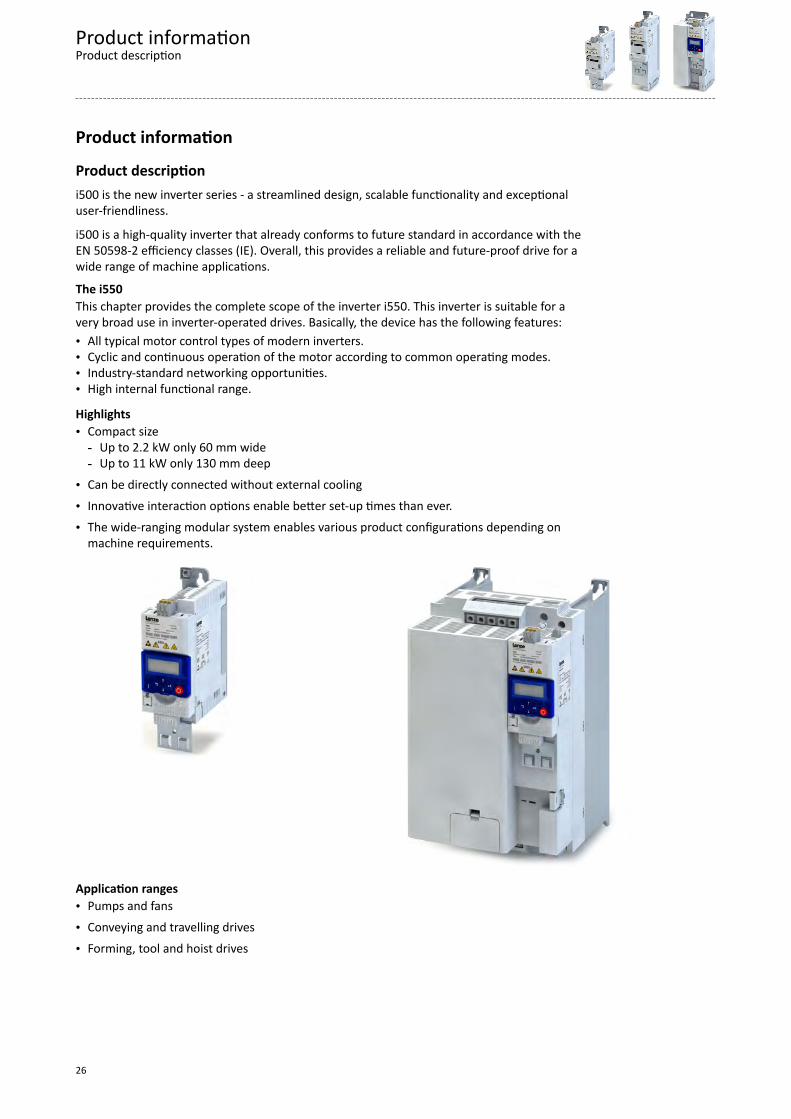
Product descriptioni500 is the new inverter series - a streamlined design, scalable functionality and exceptionaluser-friendliness.
i500 is a high-quality inverter that already conforms to future standard in accordance with theEN 50598-2 efficiency classes (IE). Overall, this provides a reliable and future-proof drive for awide range of machine applications.
The i550This chapter provides the complete scope of the inverter i550. This inverter is suitable for avery broad use in inverter-operated drives. Basically, the device has the following features:• All typical motor control types of modern inverters.• Cyclic and continuous operation of the motor according to common operating modes.• Industry-standard networking opportunities.• High internal functional range.
Highlights• Compact size- Up to 2.2 kW only 60 mm wide- Up to 11 kW only 130 mm deep
• Can be directly connected without external cooling
• Innovative interaction options enable better set-up times than ever.
• The wide-ranging modular system enables various product configurations depending onmachine requirements.
Application ranges• Pumps and fans
• Conveying and travelling drives
• Forming, tool and hoist drives
Product informationProduct description
26

Equipment
PE connecon
Mains connecon X100
Relay output X9
Network X2xx
Interface X16
Memory module X20
Control terminal X3
Shield connecon
Safety module X1
IT screw
DIP switch
Inverter status LEDs
Shield connecon
IT screw
Network status-LEDs
Motor connecon X105
Opon
CANopen/Modbus
Baud rate and bus address
(CANopen/Modbus/PROFIBUS)
PTC input X109
Control connecons
Standard-I/O or Applicaon-I/O
Diagnosc module
Interface
Brake resistor connecon X105
DC bus connecon X100
Terminal designations X... see connection plans
Position and meaning of the nameplatesComplete inverter Inverter consisting of components
①④
②
①②
①
③
① Technical data of the inverter ① Technical data of the component④ Technical data of the control unit
Type and serial number of the inverter② Type and serial number of the component③ Technical data, type and serial number of the safety module
Product informationEquipment
27
The modular system
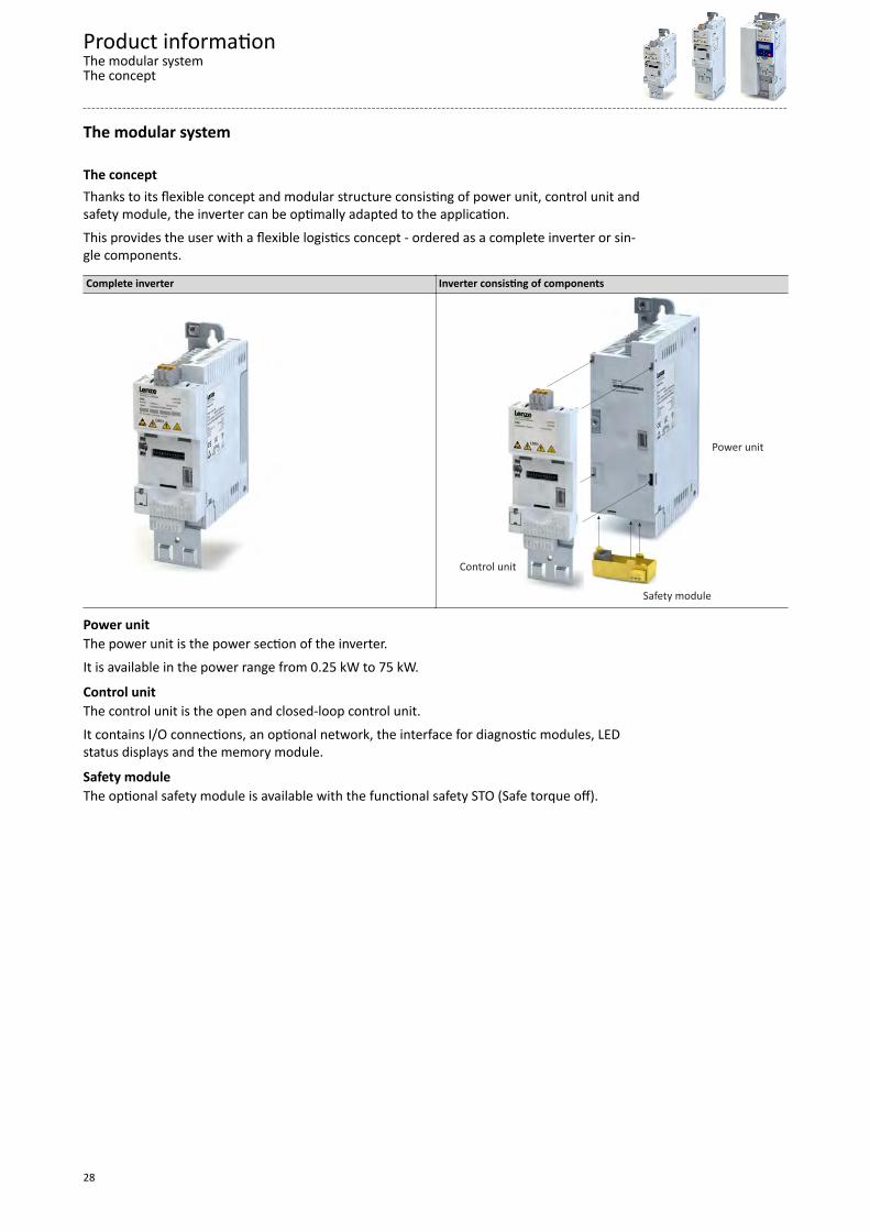
The conceptThanks to its flexible concept and modular structure consisting of power unit, control unit andsafety module, the inverter can be optimally adapted to the application.
This provides the user with a flexible logistics concept - ordered as a complete inverter or sin-gle components.
Complete inverter Inverter consisting of components
Control unit
Power unit
Safety module
Power unitThe power unit is the power section of the inverter.
It is available in the power range from 0.25 kW to 75 kW.
Control unitThe control unit is the open and closed-loop control unit.
It contains I/O connections, an optional network, the interface for diagnostic modules, LEDstatus displays and the memory module.
Safety moduleThe optional safety module is available with the functional safety STO (Safe torque off).
Product informationThe modular systemThe concept
28

Topologies / networkThe inverters can be equipped with different fieldbus networks.
The topologies and protocols typical for the prevailing networks are supported.
Currently available networks:
CANopen® is a communication protocol based on CAN.CANopen® is a registered community trademark of the CAN user organisation CiA® (CAN in Automation e. V.).The EDS device description files for CANopen can be found here:http://www.lenze.com/application-knowledge-base/artikel/200413930/0/
The Modbus protocol is an open communication protocol based on a client/server architecture and developed forthe communication with programmable logic controllers.The further development is carried out by the international user organisation Modbus Organization, USA.
PROFIBUS® (Process Field Bus) is a widely-used fieldbus system for the automation of machines and productionplants.PROFIBUS® is a registered trademark and patented technology licensed by the PROFIBUS & PROFINET International(PI) user organisation.The GSE device description files for PROFIBUS can be found here:http://www.lenze.com/application-knowledge-base/artikel/200412329/0/
EtherCAT® (Ethernet for Controller and Automation Technology) is an Ethernet-based fieldbus system which fulfilsthe application profile for industrial realtime systemsEtherCAT® is a registered trademark and patented technology, licensed by Beckhoff Automation GmbH, Germany.The XML device description files for EtherCAT can be found here:http://www.lenze.com/application-knowledge-base/artikel/200800381/0/
EtherNet/IP™ (EtherNet Industrial Protocol) is a fieldbus system based on Ethernet which uses the Common Indus-trial Protocol™ (CIP™) for data exchange.EtherNet/IP™ and Common Industrial Protocol™ (CIP™) are trademarks and patented technologies, licensed by theuser organisation ODVA (Open DeviceNet Vendor Association), USA.The EDS device description files for EtherNet/IP can be found here:http://www.lenze.com/application-knowledge-base/artikel/201207514/0/
PROFINET® (Process Field Network) is a real-time capable fieldbus system based on Ethernet.PROFINET® is a registered trademark and patented technology licensed by the PROFIBUS & PROFINET International(PI) user organisation.The GSDML device description files for PROFINET can be found here:http://www.lenze.com/application-knowledge-base/artikel/200804173/0/
More information on the supported networks can be found at http://www.lenze.com
Product informationThe modular system
Topologies / network
29

Ways of commissioningThere are three methods to commission the inverter quickly and easily.
Thanks to Lenze’s engineering philosophy, the high functionality is still easy to grasp. Parame-terisation and set-up are impressive thanks to clear structure and simple dialogues, leading tothe desired outcome quickly and reliably.• Keypad
If it’s only a matter of setting a few key parameters such as acceleration and decelerationtime, this can be done quickly on the keypad.
• Smart-Keypad-App for AndroidThe intuitive smartphone app enables adjustment to a simple application such as a con-veyor belt.
The Lenze Smart keypad app can be found in the Google Play Store.
• »EASY Starter«If functions such as the holding brake control or sequencer need to be set, it’s best to usethe »EASY Starter« engineering tool.
Product informationThe modular systemWays of commissioning
30

Functions
OverviewWith regard to their functionality, the inverters i550 are adapted to extensive applications.This is also reflected in the total scope of the products.
FunctionsMotor control Monitoring V/f characteristic control linear/square-law (VFC plus) Short circuit Sensorless vector control (SLVC) Earth fault Energy saving function (VFCeco) Device overload monitoring (i*t) Servo control for asynchronous motors (SC ASM) Motor overload monitoring (i²*t)Motor functions Mains phase failure Flying restart circuit Stalling protection Slip compensation Motor current limit DC braking Maximum torque Oscillation damping Ultimate motor current Skip frequencies Motor speed monitoring Automatic identification of the motor data Load loss detection Brake energy management Motor temperature monitoring (PTC and thermal contact) Holding brake control Diagnostics Voltage add – function Error history buffer Rotational Energy Ride Through (RERT) Logbook Speed feedback (HTL encoder) LED status displays Brake resistor control (brake chopper integrated) Keypad language selection German, English DC-bus connection (400V devices) NetworkApplication functions CANopen Process controller Modbus Process controller - idle state and rinse function PROFIBUS Freely assignable favorite menu EtherCAT Parameter change-over EtherNet/IP S-shaped ramps for smooth acceleration PROFINET Motor potentiometer Safety functions Flexible I/O configuration STO (Safe torque off) Access protection Automatic restart OEM parameter set
Motor control typesThe following table contains the possible control types with Lenze motors.
Motors V/f characteristic control Sensorless vector control ASM servo control VFCplus SLVC SC ASMThree-phase AC motors MD
MF mH m500
Product informationFunctionsOverview
31

Features
Motor setting range
Rated point 120 Hz
Only possible with Lenze MF motors.
The rated motor torque is available up to 120 Hz.
Compared to the 50-Hz operation, the setting range increases by 2.5 times.
It is quite simply not possible for a drive to be operated any more efficiently in a machine.
V/f at 120 Hz
120 Hz f
M, U
MN
UAC
V Voltage UAC Mains voltage
M Torque Mrated Rated torque
f Frequency
Rated point 87 HzThe rated motor torque is available up to 87 Hz.
Compared to the 50-Hz operation, the setting range increases by 1.74 times.
For this purpose, a motor with 230/400 V in star connection is driven by a 400-V inverter.
The inverter must be dimensioned for a rated motor current of 230 V.
V/f at 87 Hz
f
M, U
MN
UAC
fN
Product informationFeaturesMotor setting range
32

V Voltage UAC Mains voltage
M Torque Mrated Rated torque
f Frequency frated Rated frequency
Rated point 50 HzThe rated motor torque is available up to 50 Hz.
V/f at 50 Hz
f
M, U
MN
UAC
fN
V Voltage UAC Mains voltage
M Torque Mrated Rated torque
f Frequency frated Rated frequency
Product informationFeatures
Motor setting range
33
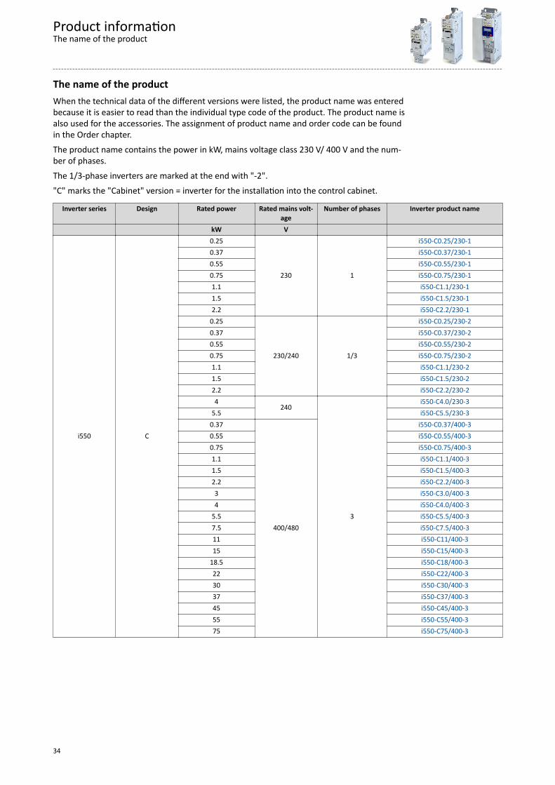
The name of the productWhen the technical data of the different versions were listed, the product name was enteredbecause it is easier to read than the individual type code of the product. The product name isalso used for the accessories. The assignment of product name and order code can be foundin the Order chapter.
The product name contains the power in kW, mains voltage class 230 V/ 400 V and the num-ber of phases.
The 1/3-phase inverters are marked at the end with "-2".
"C" marks the "Cabinet" version = inverter for the installation into the control cabinet.
Inverter series Design Rated power Rated mains volt-age
Number of phases Inverter product name
kW V
i550 C
0.25
230 1
i550-C0.25/230-10.37 i550-C0.37/230-10.55 i550-C0.55/230-10.75 i550-C0.75/230-11.1 i550-C1.1/230-11.5 i550-C1.5/230-12.2 i550-C2.2/230-1
0.25
230/240 1/3
i550-C0.25/230-20.37 i550-C0.37/230-20.55 i550-C0.55/230-20.75 i550-C0.75/230-21.1 i550-C1.1/230-21.5 i550-C1.5/230-22.2 i550-C2.2/230-24
240
3
i550-C4.0/230-35.5 i550-C5.5/230-3
0.37
400/480
i550-C0.37/400-30.55 i550-C0.55/400-30.75 i550-C0.75/400-31.1 i550-C1.1/400-31.5 i550-C1.5/400-32.2 i550-C2.2/400-33 i550-C3.0/400-34 i550-C4.0/400-3
5.5 i550-C5.5/400-37.5 i550-C7.5/400-311 i550-C11/400-315 i550-C15/400-3
18.5 i550-C18/400-322 i550-C22/400-330 i550-C30/400-337 i550-C37/400-345 i550-C45/400-355 i550-C55/400-375 i550-C75/400-3
Product informationThe name of the product
34

Technical data
Standards and operating conditions
Conformities/approvalsConformities CE 2014/35/EU Low-Voltage Directive
2014/30/EU EMC Directive (reference: CE-typical drive system)EAC TR TC 004/2011 Eurasian conformity: safety of low voltage equipment
TP TC 020/2011 Eurasian conformity: electromagnetic compatibility of technicalmeans
RoHS 2 2011/65/EU Restrictions for the use of specific hazardous materials in electricand electronic devices
Approvals UL UL 61800-5-1 for USA and Canada (requirements of the CSA 22.2 No. 274) 0.25 kW … 45 kW (55 kW … 75 kW in preparation)
Protection of persons and device protectionDegree of protection IP20 EN 60529
Type 1 NEMA 250 Protection against contact Open type only in UL-approved systemsInsulation resistance Overvoltage category III EN 61800-5-1 0 … 2000 m a.m.s.l. Overvoltage category II above 2000 m a.m.s.l.Control circuit isolation Safe mains isolation by double/reinforced insu-
lationEN 61800-5-1
Protective measures against Short circuit
earth fault Earth fault strength depends on the operating statusovervoltage Motor stalling
Motor overtemperature PTC or thermal contact, I²xt monitoringLeakage current > 3.5 mA AC, > 10 mA DC EN 61800-5-1 Observe regulations and safety instructions!Cyclic mains switching 3 times per minute Without restrictionsStarting current ≤ 3 x rated mains current
Technical dataStandards and operating conditions
Conformities/approvals
35

EMC dataActuation on public supply systems Implement measures to limit the radio interfer-
ence to be expected: The machine or plant manufacturer is responsible for compliance
with the requirements for the machine/plant! < 1 kW: with mains choke EN 61000-3-2
> 1 kW at mains current ≤ 16 A: withoutadditional measures
Mains current > 16 A: with mains choke ormains filter, with dimensioning for ratedpower. Rsce ≥ 120 is to be met.
EN 61000-3-12 RSCE: short-circuit power ratio at the connection point of themachine/plant to the public network.
Noise emission Category C1 EN 61800-3 Type-dependent, for motor cable lengths see rated data
Category C2 Noise immunity Meets requirement in compliance with EN 61800-3
Motor connectionRequirements to the shielded motor cable Capacitance per unit length
C-core-core/C-core-shield < 75/150 pF/m ≤ 2.5 mm² / AWG 14C-core-core/C-core-shield < 150/300 pF/m ≥ 4 mm² / AWG 12
Electric strength Uo/U = 0.6/1.0 kV Uo = r.m.s. value external conductor to PE
U = r.m.s. value external conductor/external conductor U ≥ 600 V UL
Environmental conditionsEnergy efficiency Class IE2 EN 50598-2 Reference: Lenze setting (switching frequency 8 kHz variable)Climate 1K3 (-25 ... +60 °C) EN 60721-3-1 Storage
2K3 (-25 ... +70 °C) EN 60721-3-2 Transport3K3 (-10 ... +55 °C) EN 60721-3-3 operation Operation at a switching frequency of 2 or 4 kHz: above +45°C,
reduce rated output current by 2.5 %/°C Operation at a switching frequency of 8 or 16 kHz: above +40°C,
reduce rated output current by 2.5 %/°CSite altitude 0 … 1000 m a.m.s.l. 1000 … 4000 m a.m.s.l. Reduce rated output current by 5 %/1000 mPollution Degree of pollution 2 EN 61800-5-1 Vibration resistance Transport
2M2 (sine, shock) EN 60721-3-2operation Amplitude 1 mm Germanischer Lloyd 5 ... 13.2 Hz
Acceleration resistant up to 0.7 g 13.2 ... 100 HzAmplitude 0.075 mm EN 61800-5-1 10 ... 57 Hz
Acceleration resistant up to 1 g 57 ... 150 Hz
Technical dataStandards and operating conditionsEMC data
36

Electrical supply conditionsThe connection to different supply forms enables a worldwide application of the inverters.The following is supported:• 1-phase mains connection 230/240 V ^ 38• 1/3-phase mains connection 230/240 V ^ 42• 3-phase mains connection 230/240 V ^ 47• 3-phase mains connection 400 V ^ 49• 3-phase mains connection 480 V ^ 59
Permissible mains systems TT Voltage to earth/ground: max. 300 V
TN IT Apply the measures described for IT systems!
IT systems are not relevant for UL-approved systems
Technical dataStandards and operating conditions
Electrical supply conditions
37
1-phase mains connection 230/240 V
Rated data
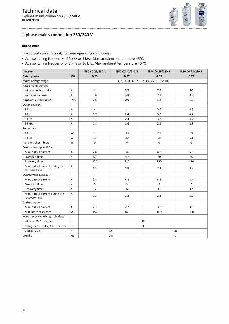
The output currents apply to these operating conditions:• At a switching frequency of 2 kHz or 4 kHz: Max. ambient temperature 45°C.• At a switching frequency of 8 kHz or 16 kHz: Max. ambient temperature 40 °C.
Inverter i550-C0.25/230-1 i550-C0.37/230-1 i550-C0.55/230-1 i550-C0.75/230-1Rated power kW 0.25 0.37 0.55 0.75Mains voltage range 1/N/PE AC 170 V ... 264 V, 45 Hz ... 65 HzRated mains current without mains choke A 4 5.7 7.6 10 with mains choke A 3.6 4.8 7.1 8.8Apparent output power kVA 0.6 0.9 1.2 1.6Output current 2 kHz A - - 3.2 4.2 4 kHz A 1.7 2.4 3.2 4.2 8 kHz A 1.7 2.4 3.2 4.2 16 kHz A 1.1 1.6 2.1 2.8Power loss 4 kHz W 15 18 23 29 8 kHz W 15 20 25 33 at controller inhibit W 6 6 6 6Overcurrent cycle 180 s Max. output current A 2.6 3.6 4.8 6.3 Overload time s 60 60 60 60 Recovery time s 120 120 120 120 Max. output current during the
recovery timeA 1.3 1.8 2.4 3.2
Overcurrent cycle 15 s Max. output current A 3.4 4.8 6.4 8.4 Overload time s 3 3 3 3 Recovery time s 12 12 12 12 Max. output current during the
recovery timeA 1.3 1.8 2.4 3.2
Brake chopper Max. output current A 2.2 2.2 3.9 3.9 Min. brake resistance Ω 180 180 100 100Max. motor cable length shielded without EMC category m 50 Category C1 (2 kHz, 4 kHz, 8 kHz) m 3 Category C2 m 15 20Weight kg 0.8 1
Technical data1-phase mains connection 230/240 VRated data
38

Inverter i550-C1.1/230-1 i550-C1.5/230-1 i550-C2.2/230-1Rated power kW 1.1 1.5 2.2Mains voltage range 1/N/PE AC 170 V ... 264 V, 45 Hz ... 65 HzRated mains current without mains choke A 14.3 16.7 22.5 with mains choke A 11.9 13.9 16.9Apparent output power kVA 2.2 2.6 3.6Output current 2 kHz A 6 7 9.6 4 kHz A 6 7 9.6 8 kHz A 6 7 9.6 16 kHz A 4 4.7 6.4Power loss 4 kHz W 37 43 60 8 kHz W 42 50 70 at controller inhibit W 6 6 6Overcurrent cycle 180 s Max. output current A 9 10.5 14.4 Overload time s 60 60 60 Recovery time s 120 120 120 Max. output current during the
recovery timeA 4.5 5.3 7.2
Overcurrent cycle 15 s Max. output current A 12 14 19.2 Overload time s 3 3 3 Recovery time s 12 12 12 Max. output current during the
recovery timeA 4.5 5.3 7.2
Brake chopper Max. output current A 12 12 12 Min. brake resistance Ω 33 33 33Max. motor cable length shielded without EMC category m 50 Category C1 (2 kHz, 4 kHz, 8 kHz) m 3 Category C2 m 20Weight kg 1.35
Technical data1-phase mains connection 230/240 V
Rated data
39

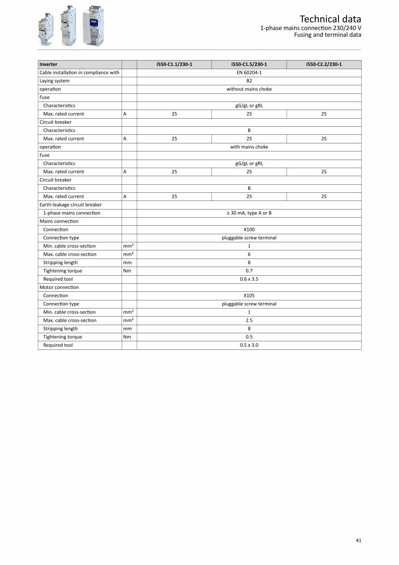
Fusing and terminal dataInverter i550-C0.25/230-1 i550-C0.37/230-1 i550-C0.55/230-1 i550-C0.75/230-1Cable installation in compliance with EN 60204-1Laying system B2operation without mains chokeFuse Characteristics gG/gL or gRL Max. rated current A 10 10 16 16Circuit breaker Characteristics B Max. rated current A 10 10 16 16operation with mains chokeFuse Characteristics gG/gL or gRL Max. rated current A 10 10 16 16Circuit breaker Characteristics B Max. rated current A 10 10 16 16Earth-leakage circuit breaker 1-phase mains connection ≥ 30 mA, type A or BMains connection Connection X100 Connection type pluggable screw terminal Min. cable cross-section mm² 1 Max. cable cross-section mm² 2.5 Stripping length mm 8 Tightening torque Nm 0.5 Required tool 0.5 x 3.0Motor connection Connection X105 Connection type pluggable screw terminal Min. cable cross-section mm² 1 Max. cable cross-section mm² 2.5 Stripping length mm 8 Tightening torque Nm 0.5 Required tool 0.5 x 3.0
Technical data1-phase mains connection 230/240 VFusing and terminal data
40
Inverter i550-C1.1/230-1 i550-C1.5/230-1 i550-C2.2/230-1Cable installation in compliance with EN 60204-1Laying system B2operation without mains chokeFuse Characteristics gG/gL or gRL Max. rated current A 25 25 25Circuit breaker Characteristics B Max. rated current A 25 25 25operation with mains chokeFuse Characteristics gG/gL or gRL Max. rated current A 25 25 25Circuit breaker Characteristics B Max. rated current A 25 25 25Earth-leakage circuit breaker 1-phase mains connection ≥ 30 mA, type A or BMains connection Connection X100 Connection type pluggable screw terminal Min. cable cross-section mm² 1 Max. cable cross-section mm² 6 Stripping length mm 8 Tightening torque Nm 0.7 Required tool 0.6 x 3.5Motor connection Connection X105 Connection type pluggable screw terminal Min. cable cross-section mm² 1 Max. cable cross-section mm² 2.5 Stripping length mm 8 Tightening torque Nm 0.5 Required tool 0.5 x 3.0
Technical data1-phase mains connection 230/240 V
Fusing and terminal data
41

1/3-phase mains connection 230/240 V
EMC filters are not integrated in inverters for this mains connection.
Technical data1/3-phase mains connection 230/240 VFusing and terminal data
42

Rated data
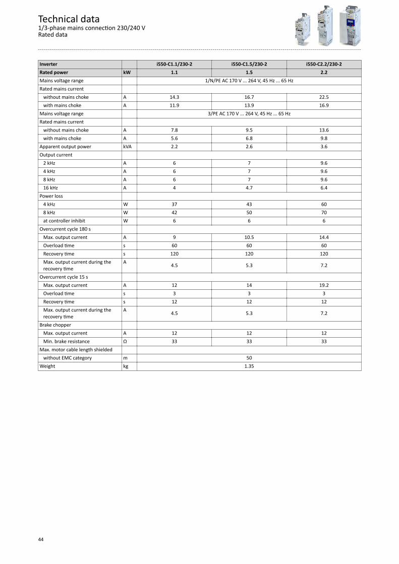
The output currents apply to these operating conditions:• At a switching frequency of 2 kHz or 4 kHz: Max. ambient temperature 45°C.• At a switching frequency of 8 kHz or 16 kHz: Max. ambient temperature 40 °C.
Inverter i550-C0.25/230-2 i550-C0.37/230-2 i550-C0.55/230-2 i550-C0.75/230-2Rated power kW 0.25 0.37 0.55 0.75Mains voltage range 1/N/PE AC 170 V ... 264 V, 45 Hz ... 65 HzRated mains current without mains choke A 4 5.7 7.6 10 with mains choke A 3.6 4.8 7.1 8.8Mains voltage range 3/PE AC 170 V ... 264 V, 45 Hz ... 65 HzRated mains current without mains choke A 2.6 3.9 4.8 6.4 with mains choke A 2 3 3.8 5.1Apparent output power kVA 0.6 0.9 1.2 1.6Output current 2 kHz A - - 3.2 4.2 4 kHz A 1.7 2.4 3.2 4.2 8 kHz A 1.7 2.4 3.2 4.2 16 kHz A 1.1 1.6 2.1 2.8Power loss 4 kHz W 15 18 23 29 8 kHz W 15 20 25 33 at controller inhibit W 6 6 6 6Overcurrent cycle 180 s Max. output current A 2.6 3.6 4.8 6.3 Overload time s 60 60 60 60 Recovery time s 120 120 120 120 Max. output current during the
recovery timeA 1.3 1.8 2.4 3.2
Overcurrent cycle 15 s Max. output current A 3.4 4.8 6.4 8.4 Overload time s 3 3 3 3 Recovery time s 12 12 12 12 Max. output current during the
recovery timeA 1.3 1.8 2.4 3.2
Brake chopper Max. output current A 2.2 2.2 3.9 3.9 Min. brake resistance Ω 180 180 100 100Max. motor cable length shielded without EMC category m 50Weight kg 0.8 1
Technical data1/3-phase mains connection 230/240 V
Rated data
43
Inverter i550-C1.1/230-2 i550-C1.5/230-2 i550-C2.2/230-2Rated power kW 1.1 1.5 2.2Mains voltage range 1/N/PE AC 170 V ... 264 V, 45 Hz ... 65 HzRated mains current without mains choke A 14.3 16.7 22.5 with mains choke A 11.9 13.9 16.9Mains voltage range 3/PE AC 170 V ... 264 V, 45 Hz ... 65 HzRated mains current without mains choke A 7.8 9.5 13.6 with mains choke A 5.6 6.8 9.8Apparent output power kVA 2.2 2.6 3.6Output current 2 kHz A 6 7 9.6 4 kHz A 6 7 9.6 8 kHz A 6 7 9.6 16 kHz A 4 4.7 6.4Power loss 4 kHz W 37 43 60 8 kHz W 42 50 70 at controller inhibit W 6 6 6Overcurrent cycle 180 s Max. output current A 9 10.5 14.4 Overload time s 60 60 60 Recovery time s 120 120 120 Max. output current during the
recovery timeA 4.5 5.3 7.2
Overcurrent cycle 15 s Max. output current A 12 14 19.2 Overload time s 3 3 3 Recovery time s 12 12 12 Max. output current during the
recovery timeA 4.5 5.3 7.2
Brake chopper Max. output current A 12 12 12 Min. brake resistance Ω 33 33 33Max. motor cable length shielded without EMC category m 50Weight kg 1.35
Technical data1/3-phase mains connection 230/240 VRated data
44

Fusing and terminal dataInverter i550-C0.25/230-2 i550-C0.37/230-2 i550-C0.55/230-2 i550-C0.75/230-2Cable installation in compliance with EN 60204-1Laying system B2operation without mains chokeFuse Characteristics gG/gL or gRL Max. rated current A 10 10 16 16Circuit breaker Characteristics B Max. rated current A 10 10 16 16operation with mains chokeFuse Characteristics gG/gL or gRL Max. rated current A 10 10 16 16Circuit breaker Characteristics B Max. rated current A 10 10 16 16Earth-leakage circuit breaker 1-phase mains connection ≥ 30 mA, type A or B 3-phase mains connection ≥ 30 mA, type BMains connection Connection X100 Connection type pluggable screw terminal Min. cable cross-section mm² 1 Max. cable cross-section mm² 2.5 Stripping length mm 8 Tightening torque Nm 0.5 Required tool 0.5 x 3.0Motor connection Connection X105 Connection type pluggable screw terminal Min. cable cross-section mm² 1 Max. cable cross-section mm² 2.5 Stripping length mm 8 Tightening torque Nm 0.5 Required tool 0.5 x 3.0
Technical data1/3-phase mains connection 230/240 V
Fusing and terminal data
45

Inverter i550-C1.1/230-2 i550-C1.5/230-2 i550-C2.2/230-2Cable installation in compliance with EN 60204-1Laying system B2operation without mains chokeFuse Characteristics gG/gL or gRL Max. rated current A 25 25 25Circuit breaker Characteristics B Max. rated current A 25 25 25operation with mains chokeFuse Characteristics gG/gL or gRL Max. rated current A 25 25 25Circuit breaker Characteristics B Max. rated current A 25 25 25Earth-leakage circuit breaker 1-phase mains connection ≥ 30 mA, type A or B 3-phase mains connection ≥ 30 mA, type BMains connection Connection X100 Connection type pluggable screw terminal Min. cable cross-section mm² 1 Max. cable cross-section mm² 6 Stripping length mm 8 Tightening torque Nm 0.7 Required tool 0.6 x 3.5Motor connection Connection X105 Connection type pluggable screw terminal Min. cable cross-section mm² 1 Max. cable cross-section mm² 2.5 Stripping length mm 8 Tightening torque Nm 0.5 Required tool 0.5 x 3.0
Technical data1/3-phase mains connection 230/240 VFusing and terminal data
46

3-phase mains connection 230/240 V
Rated data
The output currents apply to these operating conditions:• At a switching frequency of 2 kHz or 4 kHz: Max. ambient temperature 45°C.• At a switching frequency of 8 kHz or 16 kHz: Max. ambient temperature 40 °C.
Inverter i550-C4.0/230-3 i550-C5.5/230-3Rated power kW 4 5.5Mains voltage range 3/PE AC 170 V ... 264 V, 45 Hz ... 65 HzRated mains current without mains choke A 20.6 28.8 with mains choke A 15.7 21.9Apparent output power kVA 6.4 8.7Output current 2 kHz A 16.5 23 4 kHz A 16.5 23 8 kHz A 16.5 23 16 kHz A 11 15.3Power loss 4 kHz W 115 175 8 kHz W 130 195 at controller inhibit W 6 6Overcurrent cycle 180 s Max. output current A 24.8 34.5 Overload time s 60 60 Recovery time s 120 120 Max. output current during the
recovery timeA 12.4 17.3
Overcurrent cycle 15 s Max. output current A 33 46 Overload time s 3 3 Recovery time s 12 12 Max. output current during the
recovery timeA 12.4 17.3
Brake chopper Max. output current A 26 26 Min. brake resistance Ω 15 15Max. motor cable length shielded without EMC category m 50Weight kg 2.1
Technical data3-phase mains connection 230/240 V
Rated data
47

Fusing and terminal dataInverter i550-C4.0/230-3 i550-C5.5/230-3Cable installation in compliance with EN 60204-1Laying system Coperation without mains chokeFuse Characteristics gG/gL or gRL Max. rated current A 32 32Circuit breaker Characteristics B Max. rated current A 32 32operation with mains chokeFuse Characteristics gG/gL or gRL Max. rated current A 32 32Circuit breaker Characteristics B Max. rated current A 32 32Earth-leakage circuit breaker 3-phase mains connection ≥ 300 mA, type BMains connection Connection X100 Connection type Screw terminal Min. cable cross-section mm² 1.5 Max. cable cross-section mm² 6 Stripping length mm 9 Tightening torque Nm 0.5 Required tool 0.6 x 3.5Motor connection Connection X105 Connection type Screw terminal Min. cable cross-section mm² 1.5 Max. cable cross-section mm² 6 Stripping length mm 9 Tightening torque Nm 0.5 Required tool 0.6 x 3.5
Technical data3-phase mains connection 230/240 VFusing and terminal data
48

3-phase mains connection 400 V
Rated data
The output currents apply to these operating conditions:• At a switching frequency of 2 kHz or 4 kHz: Max. ambient temperature 45°C.• At a switching frequency of 8 kHz or 16 kHz: Max. ambient temperature 40 °C.
Inverter i550-C0.37/400-3 i550-C0.55/400-3 i550-C0.75/400-3 i550-C1.1/400-3Rated power kW 0.37 0.55 0.75 1.1Mains voltage range 3/PE AC 340 V ... 528 V, 45 Hz ... 65 HzRated mains current without mains choke A 1.8 2.5 3.3 4.4 with mains choke A 1.4 2 2.6 3Apparent output power kVA 0.9 1.2 1.6 2.2Output current 2 kHz A - 1.8 2.4 3.2 4 kHz A 1.3 1.8 2.4 3.2 8 kHz A 1.3 1.8 2.4 3.2 16 kHz A 0.9 1.2 1.6 2.1Power loss 4 kHz W 20 25 32 40 8 kHz W 24 31 40 51 at controller inhibit W 6 6 6 6Overcurrent cycle 180 s Max. output current A 2 2.7 3.6 4.8 Overload time s 60 60 60 60 Recovery time s 120 120 120 120 Max. output current during the
recovery timeA 1 1.4 1.8 2.4
Overcurrent cycle 15 s Max. output current A 2.6 3.6 4.8 6.4 Overload time s 3 3 3 3 Recovery time s 12 12 12 12 Max. output current during the
recovery timeA 1 1.4 1.8 2.4
Brake chopper Max. output current A 2 2 2 4.3 Min. brake resistance Ω 390 390 390 180Max. motor cable length shielded without EMC category m 15 50 Category C1 (2 kHz, 4 kHz, 8 kHz) m 3 - Category C2 m 15 20Weight kg 0.8 1 1.35
Technical data3-phase mains connection 400 V
Rated data
49
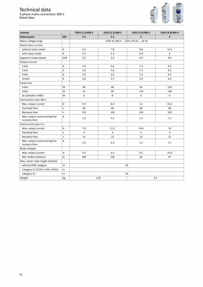
Inverter i550-C1.5/400-3 i550-C2.2/400-3 i550-C3.0/400-3 i550-C4.0/400-3Rated power kW 1.5 2.2 3 4Mains voltage range 3/PE AC 340 V ... 528 V, 45 Hz ... 65 HzRated mains current without mains choke A 5.4 7.8 9.6 12.5 with mains choke A 3.7 5.3 6.9 9Apparent output power kVA 2.6 3.6 4.9 6.4Output current 2 kHz A 3.9 5.6 7.3 9.5 4 kHz A 3.9 5.6 7.3 9.5 8 kHz A 3.9 5.6 7.3 9.5 16 kHz A 2.6 3.7 4.9 6.3Power loss 4 kHz W 48 66 85 110 8 kHz W 61 85 110 140 at controller inhibit W 6 6 6 6Overcurrent cycle 180 s Max. output current A 5.9 8.4 11 14.3 Overload time s 60 60 60 60 Recovery time s 120 120 120 120 Max. output current during the
recovery timeA 2.9 4.2 5.5 7.1
Overcurrent cycle 15 s Max. output current A 7.8 11.2 14.6 19 Overload time s 3 3 3 3 Recovery time s 12 12 12 12 Max. output current during the
recovery timeA 2.9 4.2 5.5 7.1
Brake chopper Max. output current A 4.3 4.3 9.5 16.6 Min. brake resistance Ω 180 150 82 47Max. motor cable length shielded without EMC category m 50 Category C1 (2 kHz, 4 kHz, 8 kHz) m - Category C2 m 20Weight kg 1.35 2.3
Technical data3-phase mains connection 400 VRated data
50
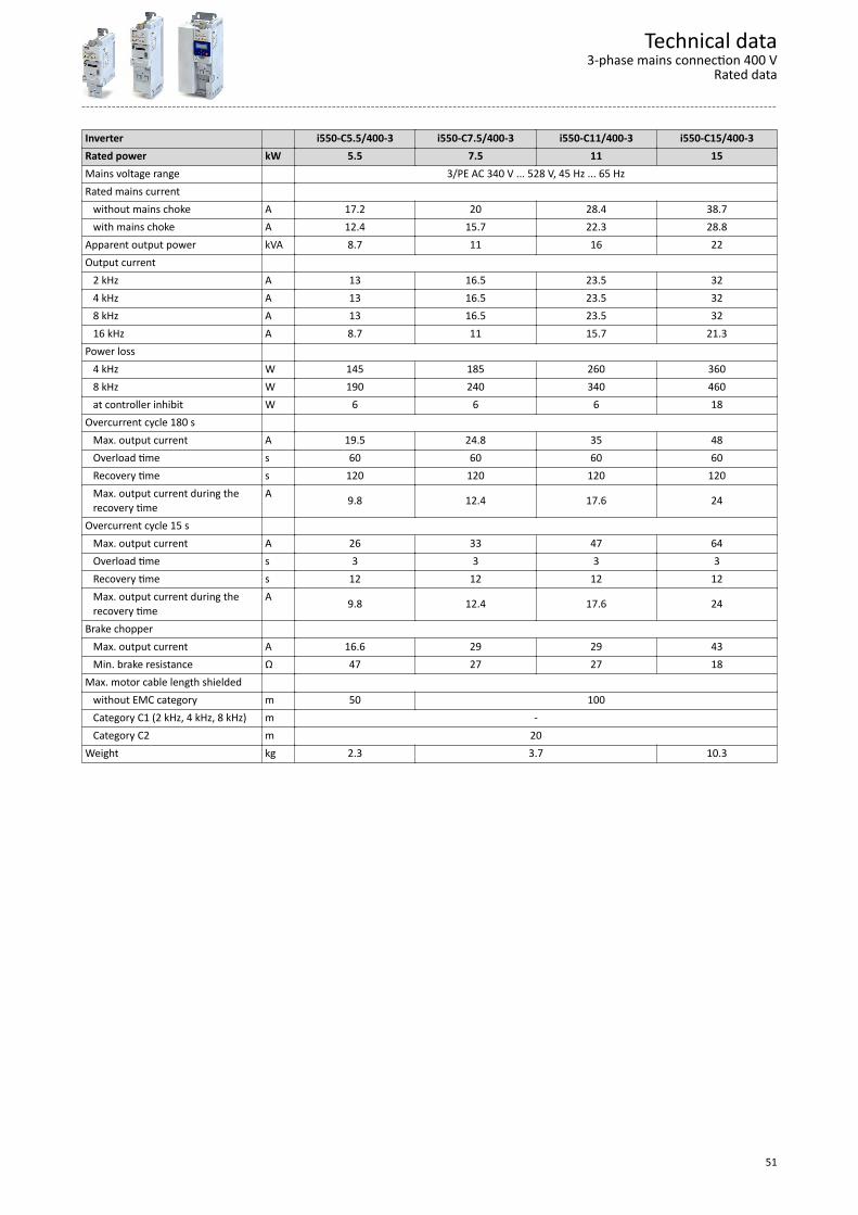
Inverter i550-C5.5/400-3 i550-C7.5/400-3 i550-C11/400-3 i550-C15/400-3Rated power kW 5.5 7.5 11 15Mains voltage range 3/PE AC 340 V ... 528 V, 45 Hz ... 65 HzRated mains current without mains choke A 17.2 20 28.4 38.7 with mains choke A 12.4 15.7 22.3 28.8Apparent output power kVA 8.7 11 16 22Output current 2 kHz A 13 16.5 23.5 32 4 kHz A 13 16.5 23.5 32 8 kHz A 13 16.5 23.5 32 16 kHz A 8.7 11 15.7 21.3Power loss 4 kHz W 145 185 260 360 8 kHz W 190 240 340 460 at controller inhibit W 6 6 6 18Overcurrent cycle 180 s Max. output current A 19.5 24.8 35 48 Overload time s 60 60 60 60 Recovery time s 120 120 120 120 Max. output current during the
recovery timeA 9.8 12.4 17.6 24
Overcurrent cycle 15 s Max. output current A 26 33 47 64 Overload time s 3 3 3 3 Recovery time s 12 12 12 12 Max. output current during the
recovery timeA 9.8 12.4 17.6 24
Brake chopper Max. output current A 16.6 29 29 43 Min. brake resistance Ω 47 27 27 18Max. motor cable length shielded without EMC category m 50 100 Category C1 (2 kHz, 4 kHz, 8 kHz) m - Category C2 m 20Weight kg 2.3 3.7 10.3
Technical data3-phase mains connection 400 V
Rated data
51

Inverter i550-C18/400-3 i550-C22/400-3 i550-C30/400-3 i550-C37/400-3Rated power kW 18.5 22 30 37Mains voltage range 3/PE AC 340 V ... 528 V, 45 Hz ... 65 HzRated mains current without mains choke A 48.4 - - - with mains choke A 36 42 54.9 68Apparent output power kVA 27 32 41 51Output current 2 kHz A 40 47 61 76 4 kHz A 40 47 61 76 8 kHz A 40 47 61 76 16 kHz A 26.6 31.3 40.7 50.7Power loss 4 kHz W 450 520 680 840 8 kHz W 570 670 880 1100 at controller inhibit W 18 18 25 25Overcurrent cycle 180 s Max. output current A 60 71 92 114 Overload time s 60 60 60 60 Recovery time s 120 120 120 120 Max. output current during the
recovery timeA 30 35 46 57
Overcurrent cycle 15 s Max. output current A 80 94 122 152 Overload time s 3 3 3 3 Recovery time s 12 12 12 12 Max. output current during the
recovery timeA 30 35 46 57
Brake chopper Max. output current A 52 52 98 98 Min. brake resistance Ω 15 15 8 8Max. motor cable length shielded without EMC category m 100 Category C1 (2 kHz, 4 kHz, 8 kHz) m - Category C2 m 20Weight kg 10.3 17.2
Technical data3-phase mains connection 400 VRated data
52
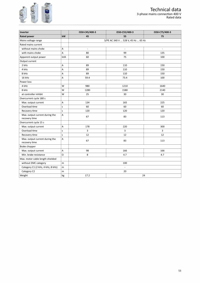
Inverter i550-C45/400-3 i550-C55/400-3 i550-C75/400-3Rated power kW 45 55 75Mains voltage range 3/PE AC 340 V ... 528 V, 45 Hz ... 65 HzRated mains current without mains choke A - - - with mains choke A 80 99 135Apparent output power kVA 60 75 100Output current 2 kHz A 89 110 150 4 kHz A 89 110 150 8 kHz A 89 110 150 16 kHz A 59.4 73.4 100Power loss 4 kHz W 980 1210 1640 8 kHz W 1280 1580 2140 at controller inhibit W 25 30 30Overcurrent cycle 180 s Max. output current A 134 165 225 Overload time s 60 60 60 Recovery time s 120 120 120 Max. output current during the
recovery timeA 67 83 113
Overcurrent cycle 15 s Max. output current A 178 220 300 Overload time s 3 3 3 Recovery time s 12 12 12 Max. output current during the
recovery timeA 67 83 113
Brake chopper Max. output current A 98 166 166 Min. brake resistance Ω 8 4.7 4.7Max. motor cable length shielded without EMC category m 100 Category C1 (2 kHz, 4 kHz, 8 kHz) m - Category C2 m 20Weight kg 17.2 24
Technical data3-phase mains connection 400 V
Rated data
53
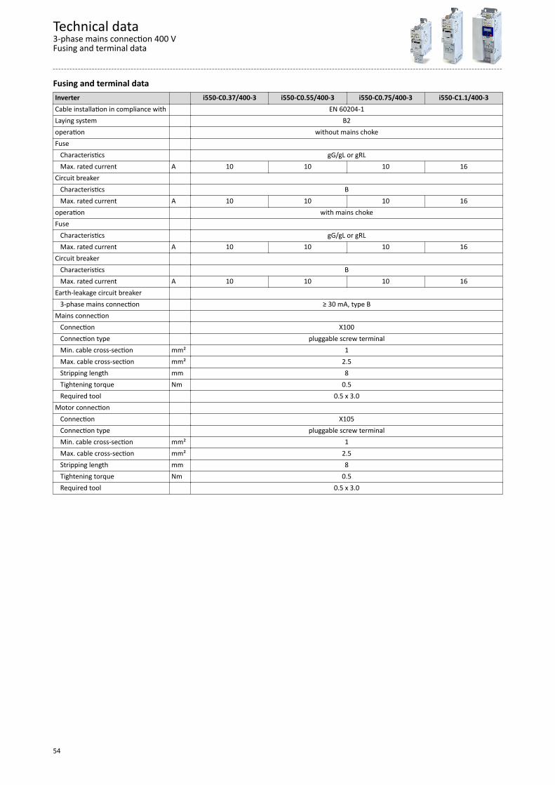
Fusing and terminal dataInverter i550-C0.37/400-3 i550-C0.55/400-3 i550-C0.75/400-3 i550-C1.1/400-3Cable installation in compliance with EN 60204-1Laying system B2operation without mains chokeFuse Characteristics gG/gL or gRL Max. rated current A 10 10 10 16Circuit breaker Characteristics B Max. rated current A 10 10 10 16operation with mains chokeFuse Characteristics gG/gL or gRL Max. rated current A 10 10 10 16Circuit breaker Characteristics B Max. rated current A 10 10 10 16Earth-leakage circuit breaker 3-phase mains connection ≥ 30 mA, type BMains connection Connection X100 Connection type pluggable screw terminal Min. cable cross-section mm² 1 Max. cable cross-section mm² 2.5 Stripping length mm 8 Tightening torque Nm 0.5 Required tool 0.5 x 3.0Motor connection Connection X105 Connection type pluggable screw terminal Min. cable cross-section mm² 1 Max. cable cross-section mm² 2.5 Stripping length mm 8 Tightening torque Nm 0.5 Required tool 0.5 x 3.0
Technical data3-phase mains connection 400 VFusing and terminal data
54

Inverter i550-C1.5/400-3 i550-C2.2/400-3 i550-C3.0/400-3 i550-C4.0/400-3Cable installation in compliance with EN 60204-1Laying system B2operation without mains chokeFuse Characteristics gG/gL or gRL Max. rated current A 16 16 25 25Circuit breaker Characteristics B Max. rated current A 16 16 25 25operation with mains chokeFuse Characteristics gG/gL or gRL Max. rated current A 16 16 25 25Circuit breaker Characteristics B Max. rated current A 16 16 25 25Earth-leakage circuit breaker 3-phase mains connection ≥ 30 mA, type B ≥ 300 mA, type BMains connection Connection X100 Connection type pluggable screw terminal Screw terminal Min. cable cross-section mm² 1 1.5 Max. cable cross-section mm² 2.5 6 Stripping length mm 8 9 Tightening torque Nm 0.5 Required tool 0.5 x 3.0 0.6 x 3.5Motor connection Connection X105 Connection type pluggable screw terminal Screw terminal Min. cable cross-section mm² 1 1.5 Max. cable cross-section mm² 2.5 6 Stripping length mm 8 9 Tightening torque Nm 0.5 Required tool 0.5 x 3.0 0.6 x 3.5
Technical data3-phase mains connection 400 V
Fusing and terminal data
55

Inverter i550-C5.5/400-3 i550-C7.5/400-3 i550-C11/400-3 i550-C15/400-3Cable installation in compliance with EN 60204-1Laying system B2operation without mains chokeFuse Characteristics gG/gL or gRL gR Max. rated current A 25 32 32 63Circuit breaker Characteristics B Max. rated current A 25 32 32 63operation with mains chokeFuse Characteristics gG/gL or gRL gR Max. rated current A 25 32 32 63Circuit breaker Characteristics B Max. rated current A 25 32 32 63Earth-leakage circuit breaker 3-phase mains connection ≥ 300 mA, type BMains connection Connection X100 Connection type Screw terminal Min. cable cross-section mm² 1.5 Max. cable cross-section mm² 6 16 35 Stripping length mm 9 11 18 Tightening torque Nm 0.5 1.2 3.8 Required tool 0.6 x 3.5 0.8 x 4.0 0.8 x 5.5Motor connection Connection X105 Connection type Screw terminal Min. cable cross-section mm² 1.5 Max. cable cross-section mm² 6 16 35 Stripping length mm 9 11 18 Tightening torque Nm 0.5 1.2 3.8 Required tool 0.6 x 3.5 0.8 x 4.0 0.8 x 5.5
Technical data3-phase mains connection 400 VFusing and terminal data
56

Inverter i550-C18/400-3 i550-C22/400-3 i550-C30/400-3 i550-C37/400-3Cable installation in compliance with EN 60204-1Laying system B2 Coperation without mains choke Fuse Characteristics gR - Max. rated current A 63 - - -Circuit breaker Characteristics B - Max. rated current A 63 - - -operation with mains chokeFuse Characteristics gR Max. rated current A 63 63 80 100Circuit breaker Characteristics B Max. rated current A 63 63 80 100Earth-leakage circuit breaker 3-phase mains connection ≥ 300 mA, type BMains connection Connection X100 Connection type Screw terminal Min. cable cross-section mm² 1.5 10 Max. cable cross-section mm² 35 50 Stripping length mm 18 19 Tightening torque Nm 3.8 4 Required tool 0.8 x 5.5 Allen key 4.0Motor connection Connection X105 Connection type Screw terminal Min. cable cross-section mm² 1.5 10 Max. cable cross-section mm² 35 50 Stripping length mm 18 19 Tightening torque Nm 3.8 4 Required tool 0.8 x 5.5 Allen key 4.0
Technical data3-phase mains connection 400 V
Fusing and terminal data
57

Inverter i550-C45/400-3 i550-C55/400-3 i550-C75/400-3Cable installation in compliance with EN 60204-1Laying system C Foperation Fuse Characteristics - Max. rated current A - - -Circuit breaker Characteristics - Max. rated current A - - -operation with mains chokeFuse Characteristics gR Max. rated current A 125 160 160Circuit breaker Characteristics B - Max. rated current A 125 - -Earth-leakage circuit breaker 3-phase mains connection ≥ 300 mA, type BMains connection Connection X100 Connection type Screw terminal Min. cable cross-section mm² 10 25 Max. cable cross-section mm² 50 95 Stripping length mm 19 22 Tightening torque Nm 4 10 Required tool Allen key 4.0 Allen key 6.0Motor connection Connection X105 Connection type Screw terminal Min. cable cross-section mm² 10 25 Max. cable cross-section mm² 50 95 Stripping length mm 19 22 Tightening torque Nm 4 10 Required tool Allen key 4.0 Allen key 6.0
Technical data3-phase mains connection 400 VFusing and terminal data
58

3-phase mains connection 480 V
Rated data
The output currents apply to these operating conditions:• At a switching frequency of 2 kHz or 4 kHz: Max. ambient temperature 45°C.• At a switching frequency of 8 kHz or 16 kHz: Max. ambient temperature 40 °C.
Inverter i550-C0.37/400-3 i550-C0.55/400-3 i550-C0.75/400-3 i550-C1.1/400-3Rated power kW 0.37 0.55 0.75 1.1Mains voltage range 3/PE AC 340 V ... 528 V, 45 Hz ... 65 HzRated mains current without mains choke A 1.5 2.1 2.8 3.7 with mains choke A 1.2 1.7 2.2 2.5Apparent output power kVA 0.9 1.2 1.6 2.2Output current 2 kHz A - 1.6 2.1 3 4 kHz A 1.1 1.6 2.1 3 8 kHz A 1.1 1.6 2.1 3 16 kHz A 0.7 1.1 1.4 2Power loss 4 kHz W 20 25 32 40 8 kHz W 24 31 40 51 at controller inhibit W 6 6 6 6Overcurrent cycle 180 s Max. output current A 1.7 2.4 3.2 4.5 Overload time s 60 60 60 60 Recovery time s 120 120 120 120 Max. output current during the
recovery timeA 0.8 1.2 1.6 2.3
Overcurrent cycle 15 s Max. output current A 2.2 3.2 4.2 6 Overload time s 3 3 3 3 Recovery time s 12 12 12 12 Max. output current during the
recovery timeA 0.8 1.2 1.6 2.3
Brake chopper Max. output current A 2 2 2 4.3 Min. brake resistance Ω 390 390 390 180Max. motor cable length shielded without EMC category m 15 50 Category C1 (2 kHz, 4 kHz, 8 kHz) m 3 - Category C2 m 15 20Weight kg 0.8 1 1.35
Technical data3-phase mains connection 480 V
Rated data
59

Inverter i550-C1.5/400-3 i550-C2.2/400-3 i550-C3.0/400-3 i550-C4.0/400-3Rated power kW 1.5 2.2 3 4Mains voltage range 3/PE AC 340 V ... 528 V, 45 Hz ... 65 HzRated mains current without mains choke A 4.5 6.5 8 10.5 with mains choke A 3.1 4.4 5.8 7.5Apparent output power kVA 2.6 3.6 4.9 6.4Output current 2 kHz A 3.5 4.8 6.3 8.2 4 kHz A 3.5 4.8 6.3 8.2 8 kHz A 3.5 4.8 6.3 8.2 16 kHz A 2.3 3.2 4.2 5.5Power loss 4 kHz W 48 66 85 110 8 kHz W 61 85 110 140 at controller inhibit W 6 6 6 6Overcurrent cycle 180 s Max. output current A 5.3 7.2 9.5 12.3 Overload time s 60 60 60 60 Recovery time s 120 120 120 120 Max. output current during the
recovery timeA 2.6 3.6 4.8 6.2
Overcurrent cycle 15 s Max. output current A 7 9.6 12.6 16.4 Overload time s 3 3 3 3 Recovery time s 12 12 12 12 Max. output current during the
recovery timeA 2.6 3.6 4.7 6.2
Brake chopper Max. output current A 4.3 4.3 9.5 16.6 Min. brake resistance Ω 180 150 82 47Max. motor cable length shielded without EMC category m 50 Category C1 (2 kHz, 4 kHz, 8 kHz) m - Category C2 m 20Weight kg 1.35 2.3
Technical data3-phase mains connection 480 VRated data
60

Inverter i550-C5.5/400-3 i550-C7.5/400-3 i550-C11/400-3 i550-C15/400-3Rated power kW 5.5 7.5 11 15Mains voltage range 3/PE AC 340 V ... 528 V, 45 Hz ... 65 HzRated mains current without mains choke A 14.3 16.6 23.7 32.3 with mains choke A 10.3 13.1 18.6 24Apparent output power kVA 8.7 11 16 22Output current 2 kHz A 11 14 21 27 4 kHz A 11 14 21 27 8 kHz A 11 14 21 27 16 kHz A 7.3 9.3 14 18Power loss 4 kHz W 145 185 260 360 8 kHz W 190 240 340 460 at controller inhibit W 6 6 6 18Overcurrent cycle 180 s Max. output current A 16.5 21 31.5 40.5 Overload time s 60 60 60 60 Recovery time s 120 120 120 120 Max. output current during the
recovery timeA 8.3 10.5 15.8 20.3
Overcurrent cycle 15 s Max. output current A 22 28 42 54 Overload time s 3 3 3 3 Recovery time s 12 12 12 12 Max. output current during the
recovery timeA 8.3 10.5 15.8 20.3
Brake chopper Max. output current A 16.6 29 29 43 Min. brake resistance Ω 47 27 27 18Max. motor cable length shielded without EMC category m 50 100 Category C1 (2 kHz, 4 kHz, 8 kHz) m - Category C2 m 20Weight kg 2.3 3.7 10.3
Technical data3-phase mains connection 480 V
Rated data
61

Inverter i550-C18/400-3 i550-C22/400-3 i550-C30/400-3 i550-C37/400-3Rated power kW 18.5 22 30 37Mains voltage range 3/PE AC 340 V ... 528 V, 45 Hz ... 65 HzRated mains current without mains choke A 40.3 47.4 - - with mains choke A 30 35.3 45.7 57Apparent output power kVA 27 32 41 51Output current 2 kHz A 34 40.4 52 65 4 kHz A 34 40.4 52 65 8 kHz A 34 40.4 52 65 16 kHz A 22.6 26.9 34.7 43.4Power loss 4 kHz W 450 520 680 840 8 kHz W 570 670 880 1100 at controller inhibit W 18 18 25 25Overcurrent cycle 180 s Max. output current A 51 61 78 98 Overload time s 60 60 60 60 Recovery time s 120 120 120 120 Max. output current during the
recovery timeA 25.5 30 39 49
Overcurrent cycle 15 s Max. output current A 68 81 104 130 Overload time s 3 3 3 3 Recovery time s 12 12 12 12 Max. output current during the
recovery timeA 25.5 30 39 49
Brake chopper Max. output current A 52 52 98 98 Min. brake resistance Ω 15 15 8 8Max. motor cable length shielded without EMC category m 100 Category C1 (2 kHz, 4 kHz, 8 kHz) m - Category C2 m 20Weight kg 10.3 17.2
Technical data3-phase mains connection 480 VRated data
62

Inverter i550-C45/400-3 i550-C55/400-3 i550-C75/400-3Rated power kW 45 55 75Mains voltage range 3/PE AC 340 V ... 528 V, 45 Hz ... 65 HzRated mains current without mains choke A - - - with mains choke A 66.7 83 113Apparent output power kVA 60 75 100Output current 2 kHz A 77 96 124 4 kHz A 77 96 124 8 kHz A 77 96 124 16 kHz A 51.4 64 82.7Power loss 4 kHz W 980 1210 1640 8 kHz W 1280 1580 2140 at controller inhibit W 25 30 30Overcurrent cycle 180 s Max. output current A 116 144 186 Overload time s 60 60 60 Recovery time s 120 120 120 Max. output current during the
recovery timeA 58 72 93
Overcurrent cycle 15 s Max. output current A 154 192 248 Overload time s 3 3 3 Recovery time s 12 12 12 Max. output current during the
recovery timeA 58 72 93
Brake chopper Max. output current A 98 166 166 Min. brake resistance Ω 8 4.7 4.7Max. motor cable length shielded without EMC category m 100 Category C1 (2 kHz, 4 kHz, 8 kHz) m - Category C2 m 20Weight kg 17.2 24
Technical data3-phase mains connection 480 V
Rated data
63

Fusing and terminal dataInverter i550-C0.37/400-3 i550-C0.55/400-3 i550-C0.75/400-3 i550-C1.1/400-3Cable installation in compliance with EN 60204-1Laying system B2operation without mains chokeFuse Characteristics gG/gL or gRL Max. rated current A 10 10 10 16Circuit breaker Characteristics B Max. rated current A 10 10 10 16operation with mains chokeFuse Characteristics gG/gL or gRL Max. rated current A 10 10 10 16Circuit breaker Characteristics B Max. rated current A 10 10 10 16Earth-leakage circuit breaker 3-phase mains connection ≥ 30 mA, type BMains connection Connection X100 Connection type pluggable screw terminal Min. cable cross-section mm² 1 Max. cable cross-section mm² 2.5 Stripping length mm 8 Tightening torque Nm 0.5 Required tool 0.5 x 3.0Motor connection Connection X105 Connection type pluggable screw terminal Min. cable cross-section mm² 1 Max. cable cross-section mm² 2.5 Stripping length mm 8 Tightening torque Nm 0.5 Required tool 0.5 x 3.0
Technical data3-phase mains connection 480 VFusing and terminal data
64
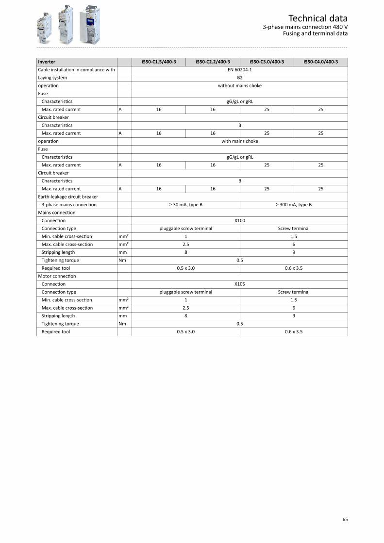
Inverter i550-C1.5/400-3 i550-C2.2/400-3 i550-C3.0/400-3 i550-C4.0/400-3Cable installation in compliance with EN 60204-1Laying system B2operation without mains chokeFuse Characteristics gG/gL or gRL Max. rated current A 16 16 25 25Circuit breaker Characteristics B Max. rated current A 16 16 25 25operation with mains chokeFuse Characteristics gG/gL or gRL Max. rated current A 16 16 25 25Circuit breaker Characteristics B Max. rated current A 16 16 25 25Earth-leakage circuit breaker 3-phase mains connection ≥ 30 mA, type B ≥ 300 mA, type BMains connection Connection X100 Connection type pluggable screw terminal Screw terminal Min. cable cross-section mm² 1 1.5 Max. cable cross-section mm² 2.5 6 Stripping length mm 8 9 Tightening torque Nm 0.5 Required tool 0.5 x 3.0 0.6 x 3.5Motor connection Connection X105 Connection type pluggable screw terminal Screw terminal Min. cable cross-section mm² 1 1.5 Max. cable cross-section mm² 2.5 6 Stripping length mm 8 9 Tightening torque Nm 0.5 Required tool 0.5 x 3.0 0.6 x 3.5
Technical data3-phase mains connection 480 V
Fusing and terminal data
65

Inverter i550-C5.5/400-3 i550-C7.5/400-3 i550-C11/400-3 i550-C15/400-3Cable installation in compliance with EN 60204-1Laying system B2operation without mains chokeFuse Characteristics gG/gL or gRL gR Max. rated current A 25 32 32 63Circuit breaker Characteristics B Max. rated current A 25 32 32 63operation with mains chokeFuse Characteristics gG/gL or gRL gR Max. rated current A 25 32 32 63Circuit breaker Characteristics B Max. rated current A 25 32 32 63Earth-leakage circuit breaker 3-phase mains connection ≥ 300 mA, type BMains connection Connection X100 Connection type Screw terminal Min. cable cross-section mm² 1.5 Max. cable cross-section mm² 6 16 35 Stripping length mm 9 11 18 Tightening torque Nm 0.5 1.2 3.8 Required tool 0.6 x 3.5 0.8 x 4.0 0.8 x 5.5Motor connection Connection X105 Connection type Screw terminal Min. cable cross-section mm² 1.5 Max. cable cross-section mm² 6 16 35 Stripping length mm 9 11 18 Tightening torque Nm 0.5 1.2 3.8 Required tool 0.6 x 3.5 0.8 x 4.0 0.8 x 5.5
Technical data3-phase mains connection 480 VFusing and terminal data
66

Inverter i550-C18/400-3 i550-C22/400-3 i550-C30/400-3 i550-C37/400-3Cable installation in compliance with EN 60204-1Laying system B2 Coperation without mains choke Fuse Characteristics gR - Max. rated current A 63 63 - -Circuit breaker Characteristics B - Max. rated current A 63 63 - -operation with mains chokeFuse Characteristics gR Max. rated current A 63 63 80 100Circuit breaker Characteristics B Max. rated current A 63 63 80 100Earth-leakage circuit breaker 3-phase mains connection ≥ 300 mA, type BMains connection Connection X100 Connection type Screw terminal Min. cable cross-section mm² 1.5 10 Max. cable cross-section mm² 35 50 Stripping length mm 18 19 Tightening torque Nm 3.8 4 Required tool 0.8 x 5.5 Allen key 4.0Motor connection Connection X105 Connection type Screw terminal Min. cable cross-section mm² 1.5 10 Max. cable cross-section mm² 35 50 Stripping length mm 18 19 Tightening torque Nm 3.8 4 Required tool 0.8 x 5.5 Allen key 4.0
Technical data3-phase mains connection 480 V
Fusing and terminal data
67

Inverter i550-C45/400-3 i550-C55/400-3 i550-C75/400-3Cable installation in compliance with EN 60204-1Laying system C Foperation Fuse Characteristics - Max. rated current A - - -Circuit breaker Characteristics - Max. rated current A - - -operation with mains chokeFuse Characteristics gR Max. rated current A 125 160 160Circuit breaker Characteristics B - Max. rated current A 125 - -Earth-leakage circuit breaker 3-phase mains connection ≥ 300 mA, type BMains connection Connection X100 Connection type Screw terminal Min. cable cross-section mm² 10 25 Max. cable cross-section mm² 50 95 Stripping length mm 19 22 Tightening torque Nm 4 10 Required tool Allen key 4.0 Allen key 6.0Motor connection Connection X105 Connection type Screw terminal Min. cable cross-section mm² 10 25 Max. cable cross-section mm² 50 95 Stripping length mm 19 22 Tightening torque Nm 4 10 Required tool Allen key 4.0 Allen key 6.0
Technical data3-phase mains connection 480 VFusing and terminal data
68

Dimensions
0.25 kW ... 0.37 kW
The dimensions in mm apply to:
0.25 kW 0.37 kW i550-C0.25/230-1 i550-C0.37/230-1 i550-C0.25/230-2 i550-C0.37/230-2 i550-C0.37/400-3
Technical dataDimensions
0.25 kW ... 0.37 kW
69
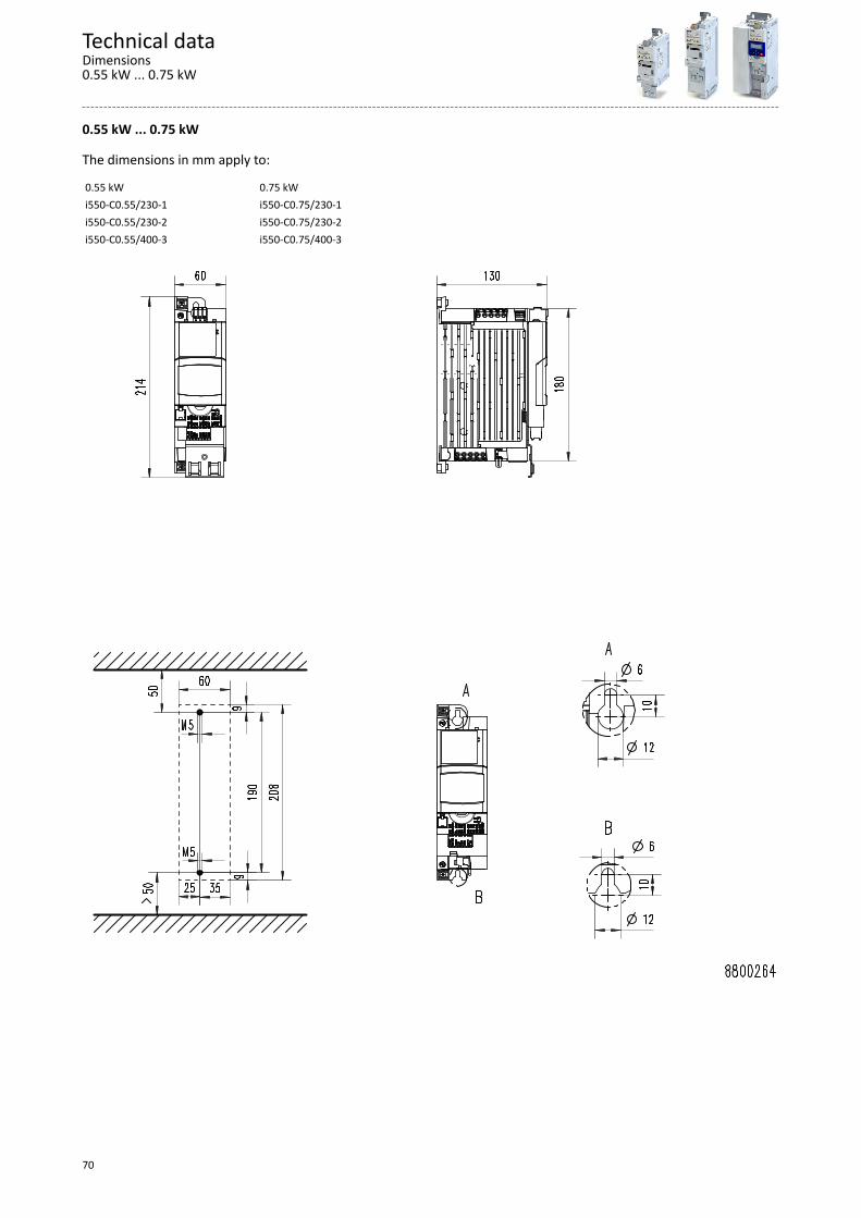
0.55 kW ... 0.75 kW
The dimensions in mm apply to:
0.55 kW 0.75 kW i550-C0.55/230-1 i550-C0.75/230-1 i550-C0.55/230-2 i550-C0.75/230-2 i550-C0.55/400-3 i550-C0.75/400-3
Technical dataDimensions0.55 kW ... 0.75 kW
70

1.1 kW ... 2.2 kW
The dimensions in mm apply to:
1.1 kW 1.5 kW 2.2 kW i550-C1.1/230-1 i550-C1.5/230-1 i550-C2.2/230-1 i550-C1.1/230-2 i550-C1.5/230-2 i550-C2.2/230-2 i550-C1.1/400-3 i550-C1.5/400-3 i550-C2.2/400-3
Technical dataDimensions
1.1 kW ... 2.2 kW
71
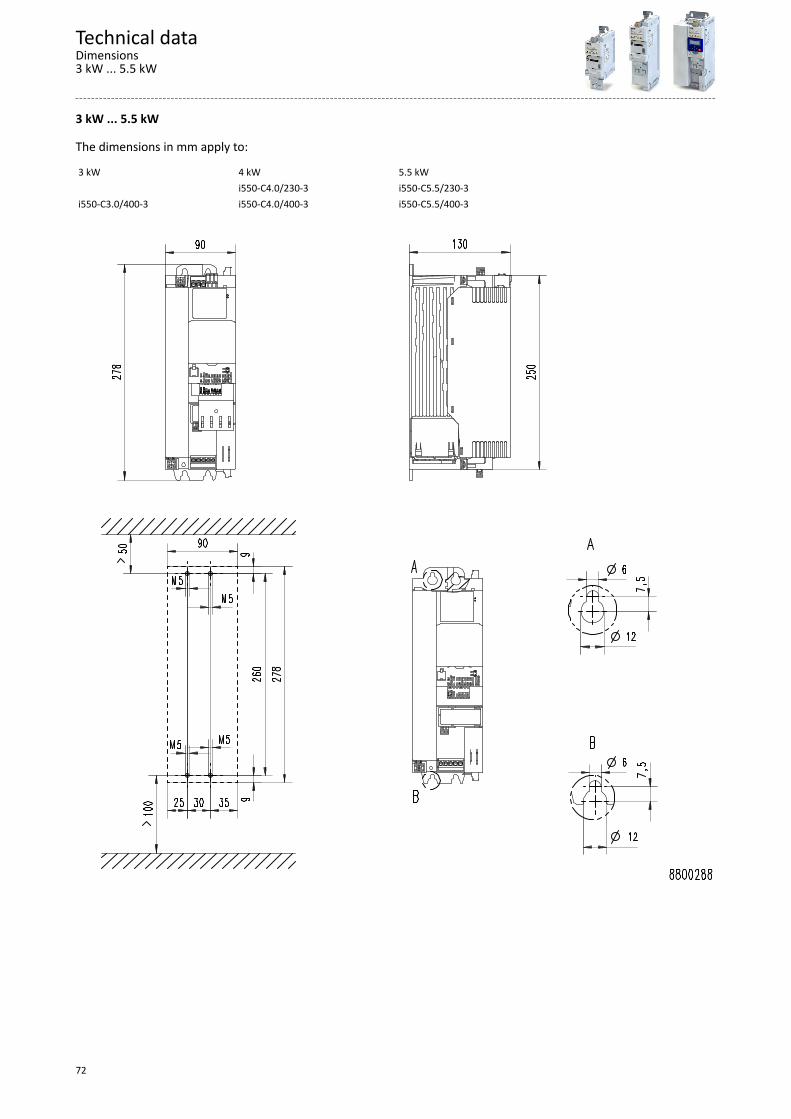
3 kW ... 5.5 kW
The dimensions in mm apply to:
3 kW 4 kW 5.5 kW i550-C4.0/230-3 i550-C5.5/230-3 i550-C3.0/400-3 i550-C4.0/400-3 i550-C5.5/400-3
Technical dataDimensions3 kW ... 5.5 kW
72

7.5 kW ... 11 kW
The dimensions in mm apply to:
7.5 kW 11 kW i550-C7.5/400-3 i550-C11/400-3
Technical dataDimensions
7.5 kW ... 11 kW
73

15 kW ... 22 kW
The dimensions in mm apply to:
15 kW 18.5 kW 22 kW i550-C15/400-3 i550-C18.5/400-3 i550-C22/400-3
Technical dataDimensions15 kW ... 22 kW
74
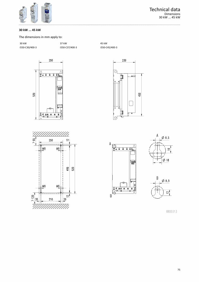
30 kW ... 45 kW
The dimensions in mm apply to:
30 kW 37 kW 45 kW i550-C30/400-3 i550-C37/400-3 i550-C45/400-3
Technical dataDimensions
30 kW ... 45 kW
75
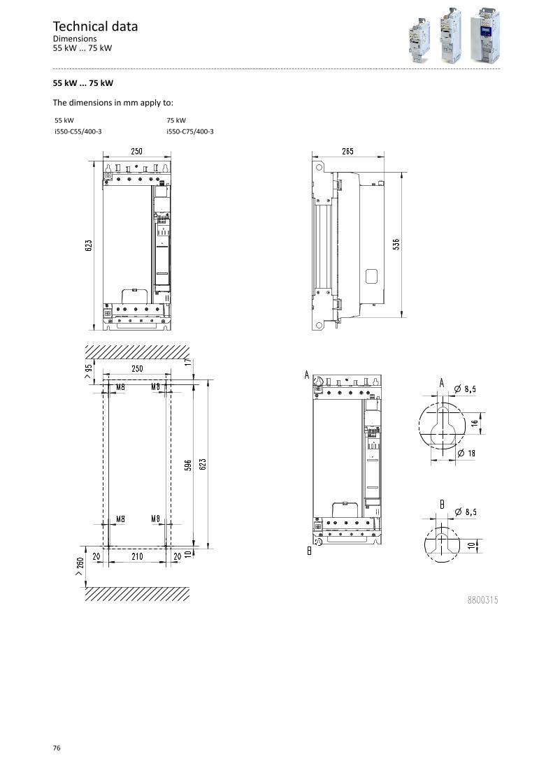
55 kW ... 75 kW
The dimensions in mm apply to:
55 kW 75 kW i550-C55/400-3 i550-C75/400-3
Technical dataDimensions55 kW ... 75 kW
76
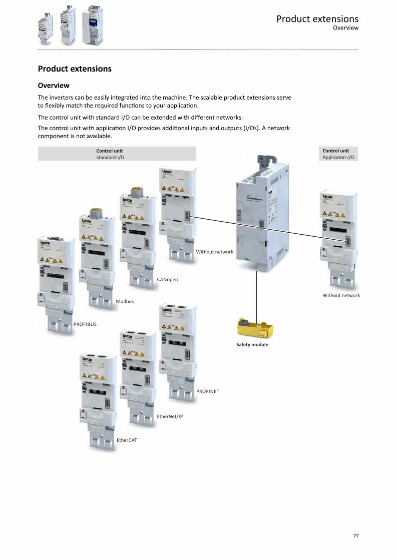
Product extensions
OverviewThe inverters can be easily integrated into the machine. The scalable product extensions serveto flexibly match the required functions to your application.
The control unit with standard I/O can be extended with different networks.
The control unit with application I/O provides additional inputs and outputs (I/Os). A networkcomponent is not available.
CANopen
EtherCAT
EtherNet/IP
Modbus
PROFIBUS
PROFINET
Safety module
Control unit
Applicaton-I/O
Control unit
Standard-I/O
Without network
Without network
Product extensionsOverview
77

I/O extensions
Standard-I/OThe standard I/O provides the inverter with analog and digital inputs and outputs and isdesigned for standard applications. The standard I/O is available with different networks.
100 mA
4.4
k
+24 V +10 V
4.4
k
4.4
k
4.4
k
4.4
k
10
mA
GN
D
DO
1
DI1
DI2
DI3
DI4
DI5
24
E
GN
D
AI1
AI2
10
V
GN
D
AO
1
24
V24
E
X3
Standard I/O
Digital inputs Terminal X3: DI1, DI2, DI3, DI4, DI5 DI3/DI4 can be optionally used as frequency orencoder input.HIGH active/LOW active switchable
Digital outputs Terminal X3: DO1 Analog inputs Terminal X3: AI1, AI2 can be optionally used as voltage or current input.Analog outputs Terminal X3: AO1 Can be optionally used as voltage or current output.24-V input Terminal X3: 24E Mains-independent DC supply of the control elec-
tronics (incl. communication)10-V output Terminal X3: 10V Reference voltage or setpoint potentiometer24-V output Terminal X3: 24V Reference potential Terminal X3: GND Connection system Pluggable spring terminal
Product extensionsI/O extensionsStandard-I/O
78

Application I/OIn addition to the standard I/O, the application I/O provides the inverter with more digital andanalog inputs and is intended for individual applications. The combination with network com-ponents is not available.
100 mA
4.4
k
+24 V +10 V
4.4
k
4.4
k
4.4
k
4.4
k
10
mA
GN
D
DO
1
DI1
DI2
DI3
DI4
DI5
24
E
GN
D
AI1
AI2
10
V
GN
D
AO
1
24
V24
E
X3 24
V4
.4k
DI7
4.4
k
AO
2 DI1
DO
2
GN
D
GN
DDI6
Applicaon I/O
Digital inputs Terminal X3: DI1, DI2, DI3, DI4, DI5, DI6, DI7 DI3/DI4 can be optionally used as frequency orencoder input.HIGH active/LOW active switchable
Digital outputs Terminal X3: DO1, DO2 Analog inputs Terminal X3: AI1, AI2 can be optionally used as voltage or current input.Analog outputs Terminal X3: AO1, AO2 Can be optionally used as voltage or current output.24-V input Terminal X3: 24E Mains-independent DC supply of the control electron-
ics (incl. communication)10-V output Terminal X3: 10V Reference voltage or setpoint potentiometer24-V output Terminal X3: 24V Reference potential Terminal X3: GND Connection system pluggable spring terminal
Product extensionsI/O extensionsApplication I/O
79

Data of control connections
Digital inputsSwitching type PNP, NPN ParameterisablePNP switching level LOW V < +5 IEC 61131−2, type 1
HIGH V > +15 NPN switching level LOW V > +15
HIGH V < +5 Input resistance kΩ 4.6 Cycle time ms 1 can be changed by software filteringElectric strength of external volt-age
V ± 30
Frequency input Connection X3/DI3, X3/DI4
Frequency range kHz 0 … 100
Encoder input Type Incremental HTL encoder
Two-track connection X3/DI3X3/DI4
Track ATrack B
Frequency range kHz 0 … 100
Digital outputsSwitching level LOW V < +5 IEC 61131−2, type 1
HIGH V > +15 max. output current mA 100 Total current for DO1 and 24VCycle time ms 1 Short-circuit strength Unlimited period Electric strength of external volt-age
V ± 30
Polarity reversal protection Integrated freewheeling diode for switching theinductive load
Overload behaviour Reduced voltage or periodic switch-off/on Reset or switch-on behaviour Output is switched off LOW
Product extensionsI/O extensionsData of control connections
80

Analog inputsCycle time
ms 1
Resolution of A/D converter
Bit 12
Operation as voltage input Connection designation X3/AI1, X3/AI2
Input voltage DC V -10 … 10 Input resistance kΩ 70 Accuracy mV ± 50 TypicalInput voltage in case of opencircuit
V - 0.2 … 0.2 Display "0"
Electric strength of externalvoltage
V ± 24
Operation as current input Connection designation X3/AI1, X3/AI2
Input current mA 0 ... 20 4 … 20 open-circuit monitored
Accuracy mA ± 0.1 TypicalInput current in case of opencircuit
mA < 0.1 Display "0"
Input resistance Ω < 250 Electric strength of externalvoltage
V ± 24
Analog outputsShort-circuit strength Unlimited period Electric strength of external volt-age
V + 24V
Operation as voltage output Resolution of D/A converter Bit 12
Output voltage DC V 0 ... 10 max. output current mA 5 Max. capacitive load µF 1 Accuracy mV ± 100 Typical
Operation as current output Output current mA 0 ... 20
4 … 20 open-circuit monitoredAccuracy mA ± 0.3 Typical
10-V outputUse Primarily for the supply of a potentiometer (1 ...
10 kΩ)
Output voltage DC Typical V 10
Accuracy mV ± 100 Max. output current mA 10 Max. capacitive load µF 1 Short-circuit strength Unlimited period Electric strength of external volt-age
V + 24
Product extensionsI/O extensions
Data of control connections
81
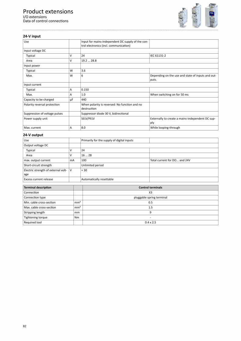
24-V inputUse Input for mains-independent DC supply of the con-
trol electronics (incl. communication)
Input voltage DC Typical V 24 IEC 61131-2
Area V 19.2 … 28.8 Input power Typical W 3.6 Max. W 6 Depending on the use and state of inputs and out-
puts.Input current Typical A 0.150
Max. A 1.0 When switching on for 50 msCapacity to be charged µF 440 Polarity reversal protection When polarity is reversed: No function and no
destruction
Suppression of voltage pulses Suppressor diode 30 V, bidirectional Power supply unit SELV/PELV Externally to create a mains-independent DC sup-
plyMax. current A 8.0 While looping-through
24-V outputUse Primarily for the supply of digital inputs Output voltage DC Typical V 24
Area V 16 … 28 max. output current mA 100 Total current for DO... and 24VShort-circuit strength Unlimited period Electric strength of external volt-age
V + 30
Excess current release Automatically resettable
Terminal description Control terminalsConnection X3Connection type pluggable spring terminalMin. cable cross-section mm² 0.5Max. cable cross-section mm² 1.5Stripping length mm 9Tightening torque Nm -Required tool 0.4 x 2.5
Product extensionsI/O extensionsData of control connections
82
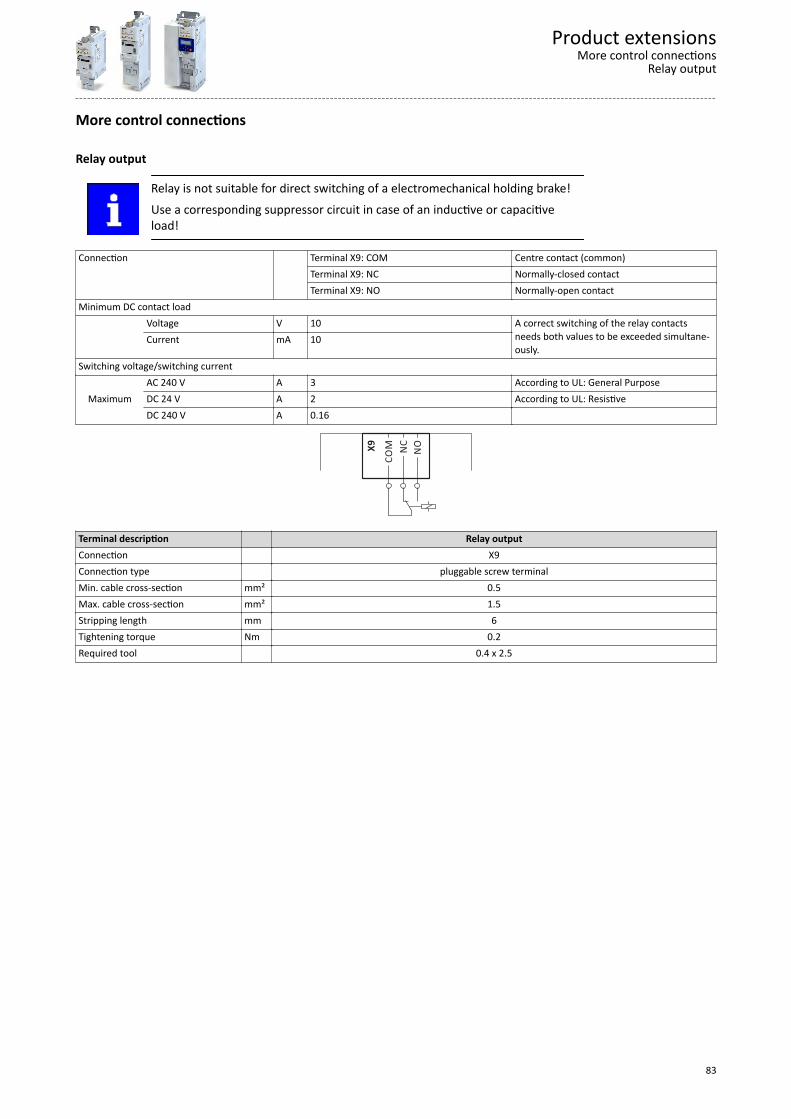
More control connections
Relay output
Relay is not suitable for direct switching of a electromechanical holding brake!
Use a corresponding suppressor circuit in case of an inductive or capacitiveload!
Connection Terminal X9: COM Centre contact (common)Terminal X9: NC Normally-closed contactTerminal X9: NO Normally-open contact
Minimum DC contact load Voltage V 10 A correct switching of the relay contacts
needs both values to be exceeded simultane-ously.
Current mA 10
Switching voltage/switching current
MaximumAC 240 V A 3 According to UL: General PurposeDC 24 V A 2 According to UL: ResistiveDC 240 V A 0.16
NC
NO
CO
MX9
Terminal description Relay outputConnection X9Connection type pluggable screw terminalMin. cable cross-section mm² 0.5Max. cable cross-section mm² 1.5Stripping length mm 6Tightening torque Nm 0.2Required tool 0.4 x 2.5
Product extensionsMore control connections
Relay output
83

PTC input
In the Lenze setting, motor temperature monitoring is activated! In the deliverystatus, there is a wire jumper between the terminals T1 and T2. Before connect-ing a thermal sensor, remove the wire jumper.
Use Connection of PTC or thermal contactConnection Terminal X109: T1 Terminal X109: T2Sensor types PTC single sensor (DIN 44081) PTC triple sensor (DIN 44082) Thermal contact
X1
09
T1
T2
Terminal description PTC inputConnection X109Connection type pluggable screw terminalMin. cable cross-section mm² 0.5Max. cable cross-section mm² 1.5Stripping length mm 6Tightening torque Nm 0.2Required tool 0.4 x 2.5
Product extensionsMore control connectionsPTC input
84

Networks
CANopenCANopen is an internationally approved communication protocol which is designed for com-mercial and industrial automation applications. High data transfer rates in connection withefficient data formatting provide for the coordination of motion control devices in multi-axisapplications.
General information Design Optional
Integrated in standard I/O
DC supply of the control electronicsand optional fieldbus
internally via the inverter Mains-dependent optionally:
External supplyMains-independent24 V DCat X3/24E...GND
Bus-related information
Name CANopen CiA 301 V4.2.0 Communication medium CAN cable in accordance with ISO 11898-2 Use Connection of the inverter to a CANopen
network
Connection system pluggable double spring terminal Status display 2 LEDs Connection designation X216: CH, CL, CG
Technical data Bus terminating resistor Ω 120 Terminated on both sides
integrated bus terminating resistor Yes Activation via DIP switchNetwork topology without repeater Line
with repeater Line or tree Station Type Slave
Max. number without repeater 127 per bus segment, incl. host systemAddress 1 ... 127 Adjustable via code or DIP switchBaud rate kbps 20, 50, 125, 250, 500, 800 or 1000 Adjustable via code or DIP switchMax. bus length m 2500, 1000, 500, 250, 100, 50 or 25 Total cable length depends on the baud
rateMax. cable length between two nodes not limited, the max. bus length is deci-
sive
Process data Transmit PDOs 3 TPDOs with 1 … 8 bytes (adjustable)
Receive PDOs 3 RPDOs with 1 … 8 bytes (adjustable) Transmission mode for TPDOs With change of data Yes
Time-controlled, multiple of ms 10 After reception 1 … 240 sync telegrams
Parameter data SDO channels Max. 2 servers
Communication time Communication time depends on
Processing time in the inverter Time between the start of a request andarrival of the response
Telegram runtime (baud rate, telegramlength)
Nesting depth of the network Bus load
Product extensionsNetworksCANopen
85

Processing time of process data Update cycle, multiple of ms 10 In the inverter
Processing time ms 0 ... 1application task runtime of the technology appli-cation used (tolerance)
ms 1 ... x
Other data Note There are no interdependencies between
parameter data and process data.
Typical topologiesLine
A1 A2 A3 An
X216 X216 X216 X216
120 120 120 120
CGCGCGCG CLCLCLCL CHCHCHCH
R R R R
Terminal description CANopenConnection X216Connection type pluggable spring terminalMin. cable cross-section mm² 0.5Max. cable cross-section mm² 2.5Stripping length mm 10Tightening torque Nm -Required tool 0.4 x 2.5
Product extensionsNetworksCANopen
86

ModbusModbus is an internationally approved, asynchronous, serial communication protocol,designed for commercial and industrial automation applications.
General information Design Optional
Integrated in standard I/O
DC supply of the control electronicsand optional fieldbus
internally via the inverter Mains-dependent optionally:
External supplyMains-independent24 V DCat X3/24E...GND
Bus-related information
Name Modbus RTU Communication medium RS485 (EIA) Use Connection of the inverter to a Modbus
network
Connection system pluggable double spring terminal Status display 2 LEDs Connection designation X216: TA, TB, COM
Technical data Communication profile Modbus RTU
Bus terminating resistor Ω 120 Terminated on both sidesintegrated bus terminating resistor Yes Activation via DIP switchNetwork topology Without repeater Line Station Type Slave
Max. number without repeater 32 per bus segment, incl. host systemMax. number with repeater 90
Address 1 ... 247 Adjustable via code or DIP switchBaud rate kbps 4.8 … 115 Adjustable via code or DIP switch, alterna-
tively automatic detection via DIP switchcan be activated
Max. cable length m 12 ... 600 Per bus segment, depending on the baudrate and the used cable type
Max. cable length between two nodes not limited, the max. bus length is deci-sive
Data channel SDO channels Max. 2 servers, with 1 … 8 bytes Supported functions:
Read Holding RegistersPreset Single RegisterPreset Multiple RegistersRead/Write 4 x registers
Communication time Communication time depends on
Processing time in the inverter Time between the start of a request andarrival of the response
Telegram runtime (baud rate, telegramlength)
Nesting depth of the network Bus load
Processing time of process data Update cycle, multiple of ms 10 In the inverter
Processing time ms 0 ... 1application task runtime of the technology appli-cation used (tolerance)
ms 1 ... x
Product extensionsNetworks
Modbus
87
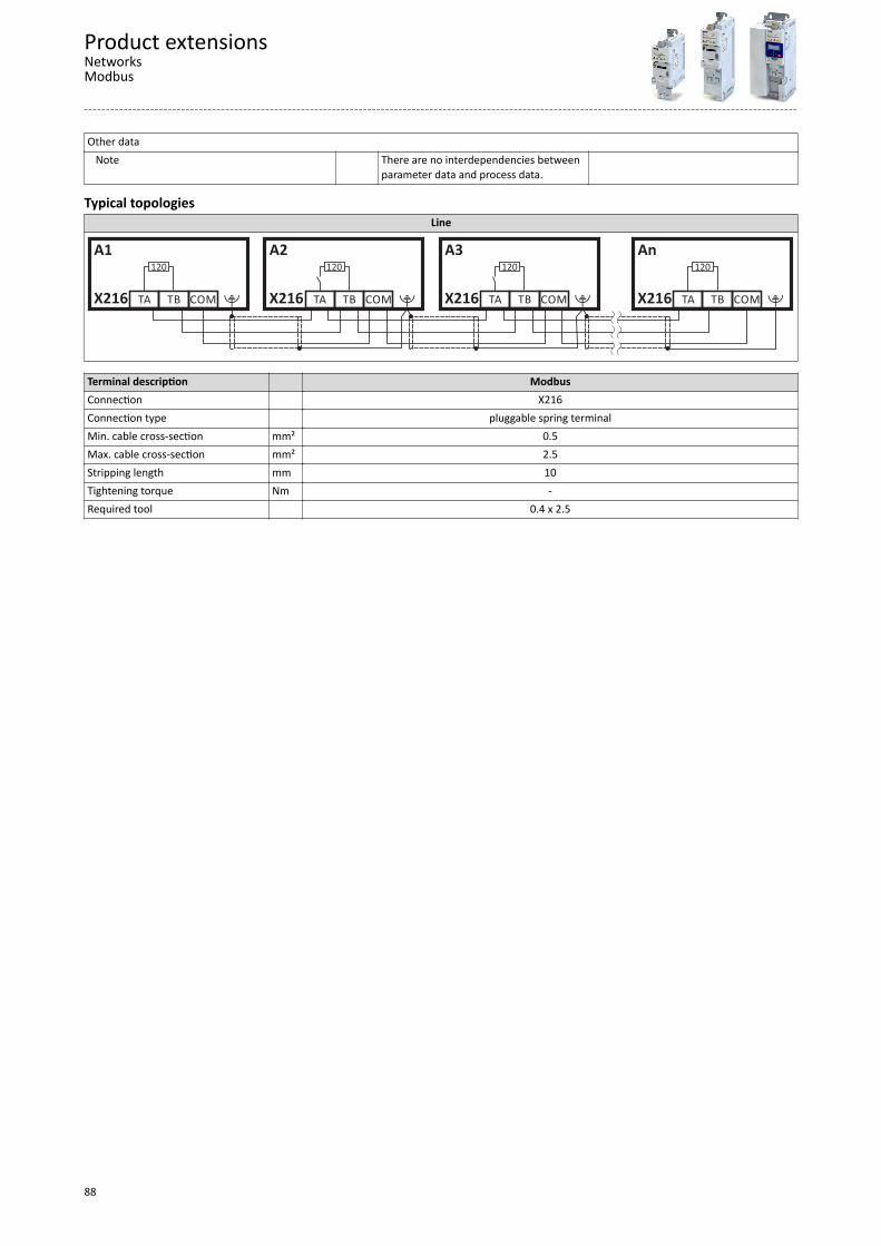
Other data Note There are no interdependencies between
parameter data and process data.
Typical topologiesLine
A1 A2 A3 An
X216 X216 X216 X216
120 120 120 120
COM COM COM COMTB TB TB TBTA TA TA TA
Terminal description ModbusConnection X216Connection type pluggable spring terminalMin. cable cross-section mm² 0.5Max. cable cross-section mm² 2.5Stripping length mm 10Tightening torque Nm -Required tool 0.4 x 2.5
Product extensionsNetworksModbus
88

PROFIBUSPROFIBUS is a common fieldbus for the connection of inverters to different control systems inplants.
General information Design Optional
Integrated in standard I/O
DC supply of the control electronicsand optional fieldbus
internally via the inverter Mains-dependent optionally:
External supplyMains-independent24 V DCat X3/24E...GND
Bus-related information
Name PROFIBUS-DP Communication medium RS485 Use Connection of the inverter to a PROFIBUS-
DP network
Connection system 9-pole Sub-D socket Status display 2 LEDs Connection designation X226: Pin 1 … 9
Technical data Communication profile PROFIBUS-DP-V0 DRIVECOM parameter data channel
PROFIBUS-DP-V1 PROFIdrive parameter data channelBus terminating resistor Ω 120 Terminated on both sidesintegrated bus terminating resistor No Network topology Without repeater Line
With repeater - Station Type Slave
Max. number without repeater 32 per bus segment, incl. host systemMax. number with repeater 125
Address 1 ... 127 Adjustable via code or DIP switchBaud rate kbps 9.6 ... 12000 Automatic detection for cable type A (EN
50170)Max. bus length m 1200 Per bus segment, depending on the baud
rate and the used cable typeMax. cable length between two nodes not limited, the max. bus length is deci-
sive
Process data PZD 1 ... 16 words (16 bits/word) in each direc-
tion
Transmission mode Data length, cyclic 1 ... 16 words, process data channel + 4
words of disconnectable parameter datachannel
Identification number 0x0E550 User data Cyclic (DP-V0) 4 bytes
Acyclic (DP-V1) Max. 240 bytes
Communication time Communication time depends on
Processing time in the inverter Time between the start of a request andarrival of the response
Telegram runtime (baud rate, telegramlength)
Nesting depth of the network Bus load
Product extensionsNetworksPROFIBUS
89
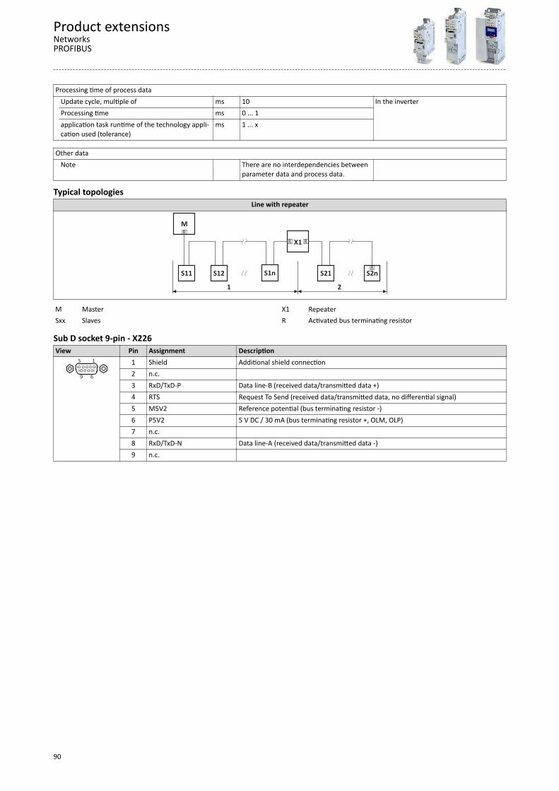
Processing time of process data Update cycle, multiple of ms 10 In the inverter
Processing time ms 0 ... 1application task runtime of the technology appli-cation used (tolerance)
ms 1 ... x
Other data Note There are no interdependencies between
parameter data and process data.
Typical topologiesLine with repeater
M
R
1
S1nS12S11
2
X1
S21 S2n
R
R R
R
M Master X1 RepeaterSxx Slaves R Activated bus terminating resistor
Sub D socket 9-pin - X226View Pin Assignment Description
1
6
5
9
5 1
9 6
1 Shield Additional shield connection2 n.c. 3 RxD/TxD-P Data line-B (received data/transmitted data +)4 RTS Request To Send (received data/transmitted data, no differential signal)5 M5V2 Reference potential (bus terminating resistor -)6 P5V2 5 V DC / 30 mA (bus terminating resistor +, OLM, OLP)7 n.c. 8 RxD/TxD-N Data line-A (received data/transmitted data -)9 n.c.
Product extensionsNetworksPROFIBUS
90

EtherCATEtherCAT is a common fieldbus for the connection of inverters to different control systems inplants.
Typical topologiesLine
IN OUT
M
R
SDnSD2SD1IN OUT IN
M Master SD Slave Device
General information Design Optional
Integrated in standard I/O
DC supply of the control electronicsand optional fieldbus
internally via the inverter Mains-dependent optionally:
External supplyMains-independent24 V DCat X3/24E...GND
Bus-related information
Name EtherCAT Communication medium Ethernet 100 Mbps, full duplex Use Connection of the inverter to an EtherCAT
network
Connection system RJ45 Status display 2 LEDs Connection designation In: X246
Out: X247
Technical data
Communication profile EtherCAT CANopen over EtherCAT (CoE)
Bus terminating resistor Ω not required integrated bus terminating resistor No Network topology Without repeater Line, switch
With repeater - Station Type EtherCAT slave
Max. number 65535 In the entire networkAddress Adjustable via parameterMax. cable length m - Not limited
The length between the TNs is decisive.Max. cable length between two nodes m 100 Process data
Transmit PDOs 16 words Receive PDOs 16 words
Cycle times ms integer multiple of 1
Product extensionsNetworksEtherCAT
91
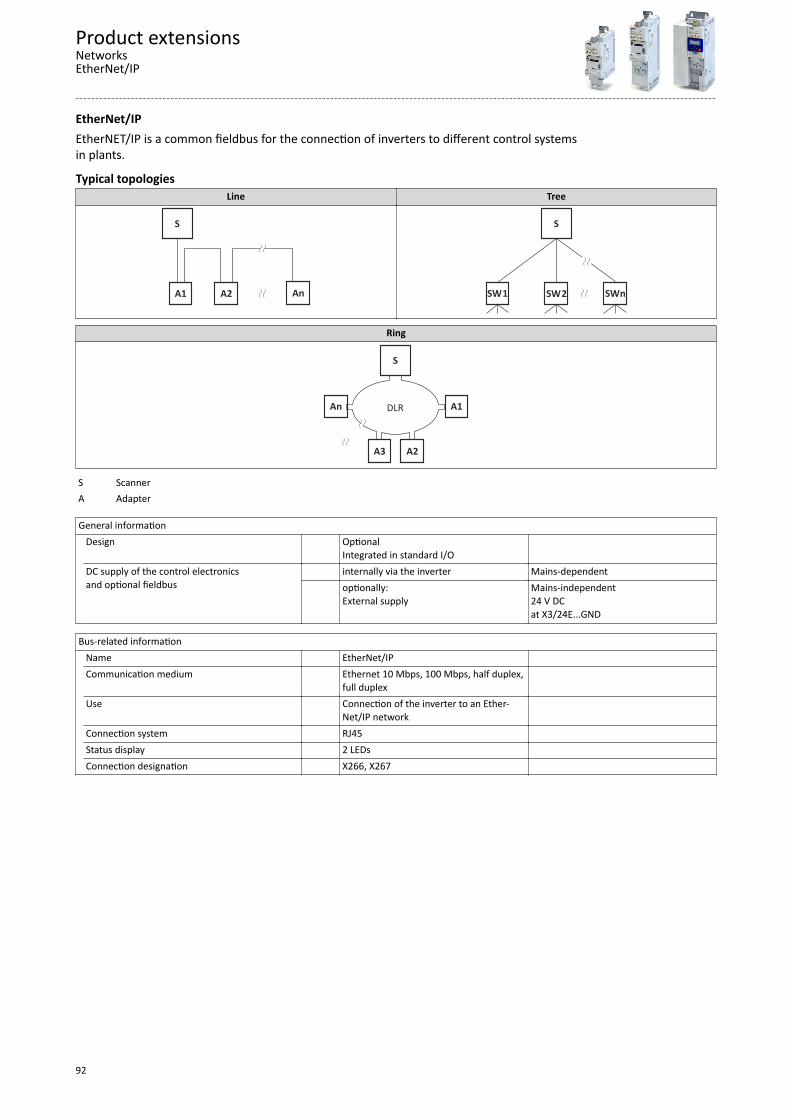
EtherNet/IPEtherNET/IP is a common fieldbus for the connection of inverters to different control systemsin plants.
Typical topologiesLine Tree
S
R
AnA2A1
S
SWnSW2SW1
Ring
S
An
A2
A1
A3
DLR
S Scanner A Adapter
General information Design Optional
Integrated in standard I/O
DC supply of the control electronicsand optional fieldbus
internally via the inverter Mains-dependent optionally:
External supplyMains-independent24 V DCat X3/24E...GND
Bus-related information
Name EtherNet/IP Communication medium Ethernet 10 Mbps, 100 Mbps, half duplex,
full duplex
Use Connection of the inverter to an Ether-Net/IP network
Connection system RJ45 Status display 2 LEDs Connection designation X266, X267
Product extensionsNetworksEtherNet/IP
92

Technical data
Communication profile EtherNet/IP AC Drive
Bus terminating resistor not required integrated bus terminating resistor No Network topology Without repeater Tree, star and line
With repeater - Station Type Adapter (slave)
Max. number 254 Per subnetworkAddress Station name Max. cable length m - Not limited
The length between the TNs is decisive.Max. cable length between two nodes m 100 Process data
Transmit PDOs 16 words Receive PDOs 16 words
Cycle time ms > 4 Switching method Store-and-Forward
Cut-Through
Switch latency µs ~ 125 At maximum telegram lengthOther data Additional TCP/IP channel
Product extensionsNetworks
EtherNet/IP
93
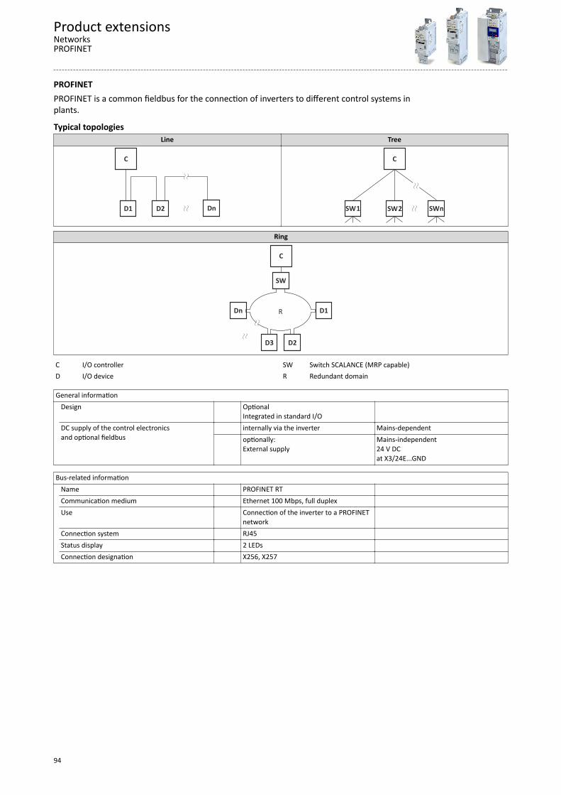
PROFINETPROFINET is a common fieldbus for the connection of inverters to different control systems inplants.
Typical topologiesLine Tree
C
R
DnD2D1
C
SWnSW2SW1
Ring
C
Dn
D2
D1
D3
R
SW
C I/O controller SW Switch SCALANCE (MRP capable)D I/O device R Redundant domain
General information Design Optional
Integrated in standard I/O
DC supply of the control electronicsand optional fieldbus
internally via the inverter Mains-dependent optionally:
External supplyMains-independent24 V DCat X3/24E...GND
Bus-related information
Name PROFINET RT Communication medium Ethernet 100 Mbps, full duplex Use Connection of the inverter to a PROFINET
network
Connection system RJ45 Status display 2 LEDs Connection designation X256, X257
Product extensionsNetworksPROFINET
94

Technical data
Communication profile PROFINET RT Bus terminating resistor not required integrated bus terminating resistor No Network topology Without repeater Tree, star and line
With repeater - Station Type I/O device with real time (RT) communica-
tion properties
Max. number 255 Per subnetworkAddress Station name Max. cable length m - Not limited
The length between the TNs is decisive.Max. cable length between two nodes m 100 Process data
Transmit PDOs 16 words Receive PDOs 16 words
Cycle time ms 2,4,8,16 Switching method Store-and-Forward Switch latency µs ~ 125 At maximum telegram lengthOther data Additional TCP/IP channel
Product extensionsNetworksPROFINET
95
Functional safety
Safety moduleIntegrated safety provides the conditions to optimise the safety functions. In comparison tothe use of standard safety engineering, integrated safety increases machine functionality andavailability. Planning and installation expenditure is reduced.
The integrated safety system can be used for the protection of persons working on machinesin accordance with the Machinery Directive.
The safety module serves to use the "safe torque off" (STO) safety function.
The motion functions are continued to be executed by the inverter. The integrated safety sys-tem monitors the safe compliance with the limit values and provides the safe inputs. If moni-tored limit values are exceeded, the integrated safety system starts control functions in theinverter according to EN 60204−1 to counteract possible errors.
Detailed information can be obtained from the "Functional safety" planningmanual.
Safety moduleOrder code VersionI5MASAV000000S STO (Safe torque off)
Product extensionsFunctional safetySafety module
96

Accessories
OverviewA package of accessories optimally matched to the inverter is available for your applications.
Moreover, the pluggable modules make commissioning and diagnostics easier.
Memory module
Mains choke
Mains filter
Brake resistor
Memory module copierSinusoidal filter
Setpoint potenometer
Power supply
Brake switch
Keypad
USB module
Blanking cover
Motor cable shield sheetWLAN module
Further accessories: terminal strips and latching terminals for the shield sheet of the controlunit.
AccessoriesOverview
97

Operation and diagnostics
KeypadParameter setting and diagnostics
Thanks to the intuitive operating structure, the navigation keys allow a quick and easy accessto the most important parameters, either to configure functions or to query current values.Parameters and actual values are indicated on the easy-to-read display.
KeypadOrder code Design
I5MADK0000000S 7-digit LED displayDisplay in German/English
USB moduleInterface to the PC
The USB 2.0‑connecting cable is used to connect the inverter with a PC with the »EASYStarter« Lenze Engineering Tool. The »EASY Starter« serves to configure the inverter via graph-ical interfaces. They create diagnostics with trend functions or monitor parameter values.
Parameterising without supplying the inverter with voltage: If you connect the inverterdirectly to the PC without a hub, in many cases the USB interface of the PC is sufficient for thevoltage supply.
Inverters with network option EtherCAT, PROFINET or EtherNET/IP must be sup-plied with an additional voltage for setting parameters if a connection cable lon-ger than 3 m is used.
Please observe the following for USB modules labelled as "PRE-SERIES": Inver-ters with network option EtherCAT, PROFINET or EtherNET/IP must always besupplied with an additional voltage for setting parameters.
USB moduleOrder code Version
I5MADU0000000S Parameter setting without voltage supply of the inverterUSB 2.0 connecting cable required
Connecting cableOrder code Length VersionEWL0085/S 3 m
USB 2.0‑connecting cable (A plug to micro-B plug)EWL0086/S 5 m
AccessoriesOperation and diagnosticsKeypad
98

WLAN moduleThe wireless interface
Wireless communication with the inverter.• via a PC with the Lenze «EASY Starter« Engineering Tool or• via the Lenze Smart keypad app for Android smartphones.
The app is recommended for adapting easy applications. The clearly arranged user interface ofthe app guides you intuitively and safely through all the menus. Operation corresponds to key-pad operation.
The Lenze Smart keypad app can be found in the Google Play Store.
WARNING!
This product contains FCC ID: QOQWF121/IC: 5123A-BGTWF121 To comply with FCC and Industry Canada RF radiation exposure limits for general popula-tion, the transmitter with its antenna must be installed such that a minimum separation dis-tance of 20 cm is maintained between the radiator (antenna) and all persons at all times.
This product must not be collocated or operated in conjunction with any other antenna ortransmitter.
- - - - - - - - - - - - - - - - - - - - - - - - - - - - - - - - - - - - - - - - - - - - - - - Le produit contient un module transmetteur certifié FCC ID: QOQWF121/IC: 5123A-
BGTWF121 Afin de se conformer aux réglementations de la FCC et d’Industry Canada relatives aux lim-
ites d’exposition aux rayonnements RF pour le grand public, le transmetteur et son antennedoivent être installés de sorte qu’une distance minimale de 20 cm soit constamment main-tenue entre le radiateur (antenne) et toute personne.
Le produit ne doit pas être utilisé en combinaison avec d’autres antennes ou transmetteurs.
AccessoriesOperation and diagnostics
WLAN module
99

LED status displaysLED 1 LED 2 LED 3 Meaning
Power (green) TX/RX (yellow) WLAN (green)Supply voltage status Communication status WLAN status
OFF OFF OFF No voltageON ON ON Self-test (approx. 1 s)ON OFF OFF Ready for operation
No active WLAN connectionON Flashing ON Communication activeON OFF Blinking Client Mode
Waiting for connectionBlinking OFF OFF Trouble
Additional conformities and approvals
CE R&TTE/REDEN 301489-1 V1.9.2:2011EN 301489-17 V2.2.1:2012EN 300328 V1.8.1:2012-06
FCC Part 15.107/15.109ICES-003
Connection data (default setting)IP address 192.168.178.1SSID <Product type>_<10-digit identifier>Password password
WLAN moduleOrder code DesignI5MADW0000000S Range in open space: 100 m, conditions on site may restrict the range.
Blanking coverProtection and optics
The blanking cover protects the terminals and provides for uniform optics if no other moduleis plugged on.
Blanking coverOrder code Version VPE PieceI5ZAA0000M Protection against dust
Uniform optics4
AccessoriesOperation and diagnosticsBlanking cover
100

Setpoint potentiometerFor the external selection of an analog setpoint.
The setpoint selection (e.g. motor speed) can be manually set via the external potentiometer.The setpoint potentiometer is connected to the analog input terminals of the inverter.
The position is displayed on the scale via the rotary knob.
The components have to be ordered separately.
Setpoint potentiometerOrder code Name VersionERPD0010K0001W Potentiometer 10 kΩ/1 WERZ0001 Rotary knob Diameter 36 mmERZ0002 Scale Scale 0 … 100 %,
Diameter 62 mm
Memory modulesFor standard set-up, Lenze offers its customers multipacked, unwritten memory modules(EPM). Together with the EPM copier, the EPMs can be duplicated at any place.
A memory module is included in the scope of supply of the inverter.
Memory moduleOrder code Version VPE Piece
I0MAPA0000000M Easily pluggableDuplicate data set with memory module copier 12
Memory module copierFor duplicating data on memory modules for a faster standard set-up.
The memory module copier is a copying system for all memory modules from Lenze. With thehelp of simple optical user guidance, the data of a module is copied quickly and reliably toanother memory module.
Memory module copierOrder code VersionEZAEDE1001 Data set copier for memory modules
AccessoriesOperation and diagnostics
Setpoint potentiometer
101

Brake resistorsTo decelerate greater moments of inertia or with a longer operation in generator mode anexternal brake resistor is required.
While the speed value is reduced by the inverter, the motor operates as generator and sup-plies energy to the inverter. The brake resistor absorbs the produced brake energy and con-verts it into heat.
AccessoriesBrake resistors
102

Inverter Brake resistor Brake resistor Order code Rated resistance Rated power Thermal capacity
Ω W kWsi550-C0.25/230-1
ERBM180R050W 180 50 7.5i550-C0.37/230-1i550-C0.55/230-1
ERBM100R100W 100 100 15i550-C0.75/230-1
i550-C1.1/230-1ERBP033R200W
33
200 30ERBP033R300W 300 45
i550-C1.5/230-1 ERBP033R200W 200 30ERBP033R300W 300 45
i550-C2.2/230-1ERBP033R200W 200 30
i550-C0.25/230-2ERBM180R050W 180 50 7.5
i550-C0.37/230-2i550-C0.55/230-2
ERBM100R100W 100 100 15i550-C0.75/230-2
i550-C1.1/230-2ERBP033R200W
33
200 30ERBP033R300W 300 45
i550-C1.5/230-2 ERBP033R200W 200 30ERBP033R300W 300 45
i550-C2.2/230-2ERBP033R200W 200 30
i550-C4.0/230-3ERBS015R800W
15
800 120ERBS015R01K2 1200 180
i550-C5.5/230-3ERBS015R800W 800 120ERBS015R01K2 1200 180
i550-C0.37/400-3ERBM390R100W 390 100 15i550-C0.55/400-3
i550-C0.75/400-3
i550-C1.1/400-3ERBP180R200W
180
200 30ERBP180R300W 300 45
i550-C1.5/400-3 ERBP180R200W 200 30ERBP180R300W 300 45
i550-C2.2/400-3ERBP180R200W
200 30i550-C3.0/400-3
ERBP082R200W82
ERBS082R780W 780 117
i550-C4.0/400-3ERBP047R200W
47
200 30ERBS047R400W 400 60ERBS047R800W 800 120
i550-C5.5/400-3ERBP047R200W 200 30ERBS047R400W 400 60ERBS047R800W 800 120
i550-C7.5/400-3ERBP027R200W
27
200 30ERBS027R600W 600 90ERBS027R01K2 1200 180
i550-C11/400-3ERBP027R200W 200 30ERBS027R600W 600 90ERBS027R01K2 1200 180
i550-C15/400-3
ERBS018R800W
18
800 120ERBS018R01K4 1400 210ERBS018R02K8 2800 420ERBG018R04K3 4300 645
AccessoriesBrake resistors
103

Inverter Brake resistor Brake resistor Order code Rated resistance Rated power Thermal capacity
Ω W kWs
i550-C18/400-3
ERBS015R800W
15
800 120ERBS015R01K2 1200 180ERBS015R02K4 2400 420ERBG015R06K2 6200 930
i550-C22/400-3
ERBS015R800W 800 120ERBS015R01K2 1200 180ERBS015R02K4 2400 420ERBG015R06K2 6200 930
i550-C30/400-3ERBG075D01K9 7.5 1900 285i550-C37/400-3
i550-C45/400-3i550-C55/400-3
ERBG005R02K6 5 2600 390i550-C75/400-3
AccessoriesBrake resistors
104

Mains chokesMains chokes reduce the effects of the inverter on the supplying mains.
The switching operations in the inverter cause high-frequency interferences that will be trans-mitted unfiltered to the supplying mains. Mains chokes smooth the steep and pulse-likecurves coming from the Inverter and make them more sinusoidal. Moreover, the effectivemains current is reduced and thus energy is saved.
Mains chokes can be used without restrictions in conjunction with RFI filters.
Please note that the use of a mains choke reduces the mains voltage at the input of the inver-ter. The typical voltage drop across the mains choke is around 4 % at its rated point.
Inverters from 22 kW must always be used together with mains chokes.
1-phase mains connection 230/240 VInverter Mains choke Order code Number of phases Rated current Inductance
A mHi550-C0.25/230-1
ELN1-0900H005
1
5 9i550-C0.37/230-1i550-C0.55/230-1
ELN1-0500H009 9 5i550-C0.75/230-1i550-C1.1/230-1
ELN1-0250H018 18 2.5i550-C1.5/230-1i550-C2.2/230-1
1/3-phase mains connection 230/240 VInverter Mains choke Order code Number of phases Rated current Inductance
A mH
i550-C0.25/230-2ELN1-0900H005 1 5 9EZAELN3002B153 3 2 14.7
i550-C0.37/230-2ELN1-0900H005 1 5 9EZAELN3004B742 3 4 7.35
i550-C0.55/230-2ELN1-0500H009 1 9 5EZAELN3004B742 3 4 7.35
i550-C0.75/230-2ELN1-0500H009 1 9 5EZAELN3006B492 3 6 4.9
i550-C1.1/230-2ELN1-0250H018 1 18 2.5EZAELN3006B492 3 6 4.9
i550-C1.5/230-2ELN1-0250H018 1 18 2.5EZAELN3008B372 3 8 3.68
i550-C2.2/230-2ELN1-0250H018 1 18 2.5EZAELN3010B292 3 10 2.94
AccessoriesMains chokes
1-phase mains connection 230/240 V
105

3-phase mains connection 230/240 VInverter Mains choke Order code Number of phases Rated current Inductance
A mHi550-C4.0/230-3 EZAELN3016B182
316 1.84
i550-C5.5/230-3 EZAELN3025B122 25 1.18
3-phase mains connection 400 VInverter Mains choke Order code Number of phases Rated current Inductance
A mHi550-C0.37/400-3 EZAELN3002B203
3
1.5 19.6i550-C0.55/400-3 EZAELN3002B153 2 14.7i550-C0.75/400-3
EZAELN3004B742 4 7.35i550-C1.1/400-3i550-C1.5/400-3i550-C2.2/400-3 EZAELN3006B492 6 4.9i550-C3.0/400-3 EZAELN3008B372 8 3.68i550-C4.0/400-3 EZAELN3010B292 10 2.94i550-C5.5/400-3
EZAELN3016B182 16 1.84i550-C7.5/400-3i550-C11/400-3 EZAELN3025B122 25 1.18i550-C15/400-3 EZAELN3030B981 30 0.98i550-C18/400-3 EZAELN3040B741 40 0.74i550-C22/400-3 EZAELN3045B651 45 0.65i550-C30/400-3 EZAELN3063B471 63 0.47i550-C37/400-3
EZAELN3080B371 80 0.37i550-C45/400-3i550-C55/400-3 EZAELN3100B301 100 0.3i550-C75/400-3 EZAELN3160B191 160 0.19
3-phase mains connection 480 VInverter Mains choke Order code Number of phases Rated current Inductance
A mHi550-C0.37/400-3 EZAELN3002B203
3
1.5 19.6i550-C0.55/400-3 EZAELN3002B153 2 14.7i550-C0.75/400-3
EZAELN3004B742 4 7.35i550-C1.1/400-3i550-C1.5/400-3i550-C2.2/400-3
EZAELN3006B492 6 4.9i550-C3.0/400-3i550-C4.0/400-3 EZAELN3008B372 8 3.68i550-C5.5/400-3
EZAELN3016B182 16 1.84i550-C7.5/400-3i550-C11/400-3 EZAELN3020B152 20 1.47i550-C15/400-3 EZAELN3025B122 25 1.18i550-C18/400-3 EZAELN3030B981 30 0.98i550-C22/400-3 EZAELN3040B741 40 0.74i550-C30/400-3 EZAELN3050B591 50 0.59i550-C37/400-3 EZAELN3063B471 63 0.47i550-C45/400-3 EZAELN3080B371 80 0.37i550-C55/400-3 EZAELN3090B331 90 0.33i550-C75/400-3 EZAELN3125B241 125 0.24
AccessoriesMains chokes3-phase mains connection 230/240 V
106

RFI filters / Mains filtersRFI and mains filters are used to ensure compliance with the EMC requirements of EuropeanStandard EN 61800-3. This standard defines the EMC requirements for electrical drive systemin various categories.• RFI filters are capacitive accessory components. RFI filters reduce conducted noise emis-
sions. RFI filters are also called EMC filters.• Mains filters are a combination of mains choke and RFI filter. Mains filters reduce the con-
ducted noise emission.
Definition of the environments(EN 61800−3)
First environmentThe first environment comprises residential buildings or locations that are directly connectedto a low-voltage system for supplying residential areas.
Second environmentThe second environment comprises facilities or locations that are not directly connected to alow-voltage system for supplying residential areas.
Category C1Category C1 defines the requirements for drive systems that are intended for the use in thefirst environment at a rated voltage lower than 1000 V.
The limit values of the EN 61800−3 comply with EN 55011 class B.
Category C2Category C2 defines the requirements for permanently installed drive systems that are inten-ded for the use in the first environment at a rated voltage lower than 1000 V. Installation andcommissioning must only be carried out by qualified personnel with EMC knowledge.
The limit values of the EN 61800−3 comply with EN 55011 class A group 1.
Category C3Category C3 defines the requirements for drive systems that are exclusively intended for theuse in the second environment at a rated voltage lower than 1000 V.
The limit values of the EN 61800−3 comply with EN 55011 class A group 2.
When working with stricter line-bound noise emission requirements which can-not be met using the radio interference suppression measures integrated in theinverter, external filters can be used. The filters can be installed below or next tothe inverter.
If necessary, the internal filters have to be deactivated when external filters areused. For this purpose, remove the IT screws of the inverters.
AccessoriesRFI filters / Mains filters
107
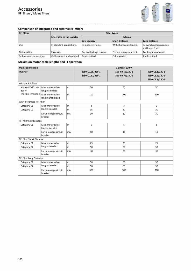
Comparison of integrated and external RFI filtersRFI filters Filter types
Integrated in the inverter ExternalLow Leakage Short Distance Long Distance
Use In standard applications. In mobile systems. With short cable length. At switching frequencies4 kHz and 8 kHz.
Optimisation Easy use. For low leakage current. For low leakage current. For long motor cable.Reduces noise emissions Cable-guided and radiated Cable-guided Cable-guided Cable-guided
Maximum motor cable lengths and FI operation
Mains connection 1-phase, 230 VInverter i550-C0.25/230-1 i550-C0.55/230-1 i550-C1.1/230-1 i550-C0.37/230-1 i550-C0.75/230-1 i550-C1.5/230-1 i550-C2.2/230-1Without RFI filter without EMC cat-
egoryThermal limitation
Max. motor cablelength shielded
m 50 50 50
Max. motor cablelength unshielded
m 100 100 200
With integrated RFI filter Category C1 Max. motor cable
length shieldedm 3 3 3
Category C2 m 15 20 20 Earth-leakage circuit
breakermA 30 30 30
RFI filter Low Leakage Category C1 Max. motor cable
length shieldedm 5 5 5
Earth-leakage circuitbreaker
mA 10 10 10
RFI filter Short Distance Category C1 Max. motor cable
length shieldedm 25 25 25
Category C2 m 50 50 50 Earth-leakage circuit
breakermA 30 30 30
RFI filter Long Distance Category C1 Max. motor cable
length shieldedm 50 50 50
Category C2 m 50 50 50 Earth-leakage circuit
breakermA 300 300 300
AccessoriesRFI filters / Mains filters
108
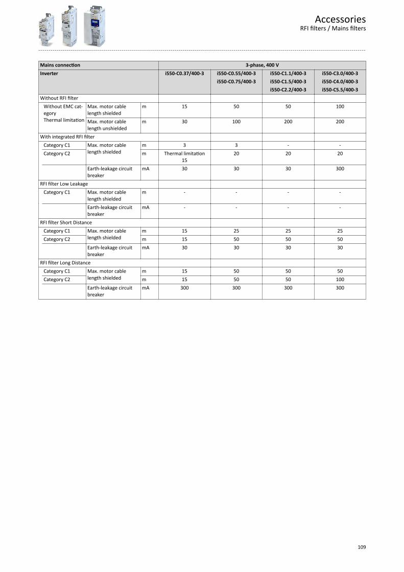
Mains connection 3-phase, 400 VInverter i550-C0.37/400-3 i550-C0.55/400-3 i550-C1.1/400-3 i550-C3.0/400-3 i550-C0.75/400-3 i550-C1.5/400-3 i550-C4.0/400-3 i550-C2.2/400-3 i550-C5.5/400-3Without RFI filter Without EMC cat-
egoryThermal limitation
Max. motor cablelength shielded
m 15 50 50 100
Max. motor cablelength unshielded
m 30 100 200 200
With integrated RFI filter Category C1 Max. motor cable
length shieldedm 3 3 - -
Category C2 m Thermal limitation15
20 20 20
Earth-leakage circuitbreaker
mA 30 30 30 300
RFI filter Low Leakage Category C1 Max. motor cable
length shieldedm - - - -
Earth-leakage circuitbreaker
mA - - - -
RFI filter Short Distance Category C1 Max. motor cable
length shieldedm 15 25 25 25
Category C2 m 15 50 50 50 Earth-leakage circuit
breakermA 30 30 30 30
RFI filter Long Distance Category C1 Max. motor cable
length shieldedm 15 50 50 50
Category C2 m 15 50 50 100 Earth-leakage circuit
breakermA 300 300 300 300
AccessoriesRFI filters / Mains filters
109
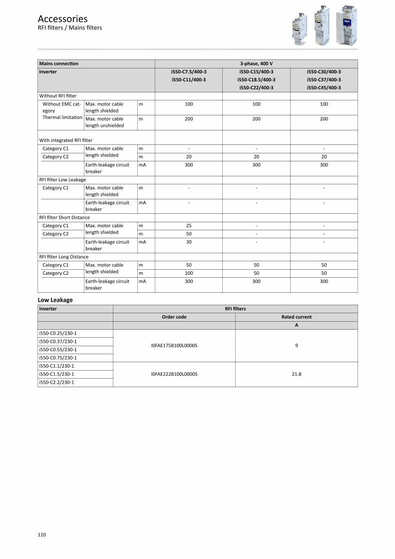
Mains connection 3-phase, 400 VInverter i550-C7.5/400-3 i550-C15/400-3 i550-C30/400-3 i550-C11/400-3 i550-C18.5/400-3 i550-C37/400-3 i550-C22/400-3 i550-C45/400-3Without RFI filter Without EMC cat-
egoryThermal limitation
Max. motor cablelength shielded
m 100 100 100
Max. motor cablelength unshielded
m 200 200 200
With integrated RFI filter
Category C1 Max. motor cablelength shielded
m - - - Category C2 m 20 20 20 Earth-leakage circuit
breakermA 300 300 300
RFI filter Low Leakage Category C1 Max. motor cable
length shieldedm - - -
Earth-leakage circuitbreaker
mA - - -
RFI filter Short Distance Category C1 Max. motor cable
length shieldedm 25 - -
Category C2 m 50 - - Earth-leakage circuit
breakermA 30 - -
RFI filter Long Distance Category C1 Max. motor cable
length shieldedm 50 50 50
Category C2 m 100 50 50 Earth-leakage circuit
breakermA 300 300 300
Low LeakageInverter RFI filters Order code Rated current Ai550-C0.25/230-1
I0FAE175B100L0000S 9i550-C0.37/230-1i550-C0.55/230-1i550-C0.75/230-1i550-C1.1/230-1
I0FAE222B100L0000S 21.8i550-C1.5/230-1i550-C2.2/230-1
AccessoriesRFI filters / Mains filters
110

Short DistanceInverter RFI filters Order code Rated current Ai550-C0.25/230-1
I0FAE175B100S0000S 9i550-C0.37/230-1i550-C0.55/230-1i550-C0.75/230-1i550-C1.1/230-1
I0FAE222B100S0000S 21.8i550-C1.5/230-1i550-C2.2/230-1i550-C0.37/400-3
I0FAE175F100S0000S 3.3i550-C0.55/400-3i550-C0.75/400-3i550-C1.1/400-3
I0FAE222F100S0000S 7.3i550-C1.5/400-3i550-C2.2/400-3i550-C3.0/400-3
I0FAE255F100S0000S 18.0i550-C4.0/400-3i550-C5.5/400-3i550-C7.5/400-3
I0FAE311F100S0000S 29.0i550-C11/400-3
Long DistanceInverter RFI filters Order code Rated current Ai550-C0.25/230-1
I0FAE175B100D0000S 9.0i550-C0.37/230-1i550-C0.55/230-1i550-C0.75/230-1i550-C1.1/230-1
I0FAE222B100D0000S 21.8i550-C1.5/230-1i550-C2.2/230-1i550-C4.0/230-3
- -i550-C5.5/230-3i550-C0.37/400-3
I0FAE175F100D0000S 3.3i550-C0.55/400-3i550-C0.75/400-3i550-C1.1/400-3
I0FAE222F100D0000S 7.3i550-C1.5/400-3i550-C2.2/400-3i550-C3.0/400-3
I0FAE255F100D0000S 18.0i550-C4.0/400-3i550-C5.5/400-3i550-C7.5/400-3
I0FAE311F100D0000S 29.0i550-C11/400-3
AccessoriesRFI filters / Mains filters
111

Mains filtersInverter Mains filters Order code Rated current Ai550-C15/400-3
E84AZESR1834LD 50.4i550-C18/400-3i550-C22/400-3 E84AZESM2234LD 42.0i550-C30/400-3 E84AZESM3034LD 55.0i550-C37/400-3 E84AZESM3734LD 68.0i550-C45/400-3 E84AZESM4534LD 80.0
Sine filterA sinusoidal filter in the motor cable limits the rate of voltage rise and the capacitive charge/discharge currents that occur during inverter operation.
Only use a sinusoidal filter with standard asynchronous motors 0 to 550 V.
Operation only with V/f or square-law V/f characteristic control.
Set the switching frequency permanently to the specified value.
Limit the output frequency of the inverter to the given value.
Inverter Sinusoidal filters Switching frequency Order code Rated inductance Max. output frequency kHz mH Hzi550-C0.37/400-3
48
EZS3-004A200 11.0
150
i550-C0.55/400-3i550-C0.75/400-3i550-C1.1/400-3i550-C1.5/400-3
EZS3-010A200 5.10i550-C2.2/400-3i550-C3.0/400-3i550-C4.0/400-3
EZS3-017A200 3.07i550-C5.5/400-3i550-C7.5/400-3 EZS3-024A200 2.50i550-C11/400-3 EZS3-032A200 2.00i550-C15/400-3 EZS3-037A200 1.70i550-C18/400-3 EZS3-048A200 1.20i550-C22/400-3 EZS3-061A200 1.00
AccessoriesRFI filters / Mains filters
112
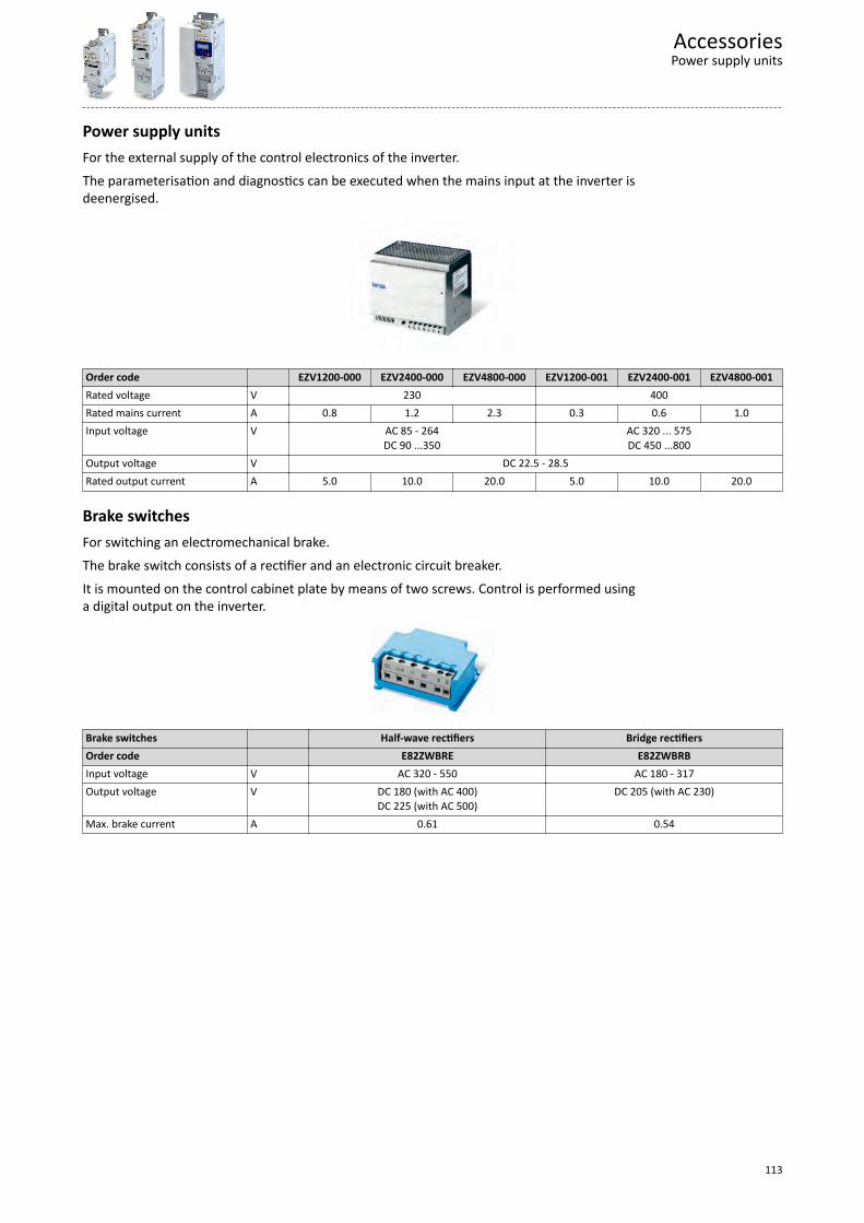
Power supply unitsFor the external supply of the control electronics of the inverter.
The parameterisation and diagnostics can be executed when the mains input at the inverter isdeenergised.
Order code EZV1200-000 EZV2400-000 EZV4800-000 EZV1200-001 EZV2400-001 EZV4800-001Rated voltage V 230 400Rated mains current A 0.8 1.2 2.3 0.3 0.6 1.0Input voltage V AC 85 - 264
DC 90 ...350AC 320 ... 575DC 450 ...800
Output voltage V DC 22.5 - 28.5Rated output current A 5.0 10.0 20.0 5.0 10.0 20.0
Brake switchesFor switching an electromechanical brake.
The brake switch consists of a rectifier and an electronic circuit breaker.
It is mounted on the control cabinet plate by means of two screws. Control is performed usinga digital output on the inverter.
Brake switches Half-wave rectifiers Bridge rectifiersOrder code E82ZWBRE E82ZWBRBInput voltage V AC 320 - 550 AC 180 - 317Output voltage V DC 180 (with AC 400)
DC 225 (with AC 500)DC 205 (with AC 230)
Max. brake current A 0.61 0.54
AccessoriesPower supply units
113
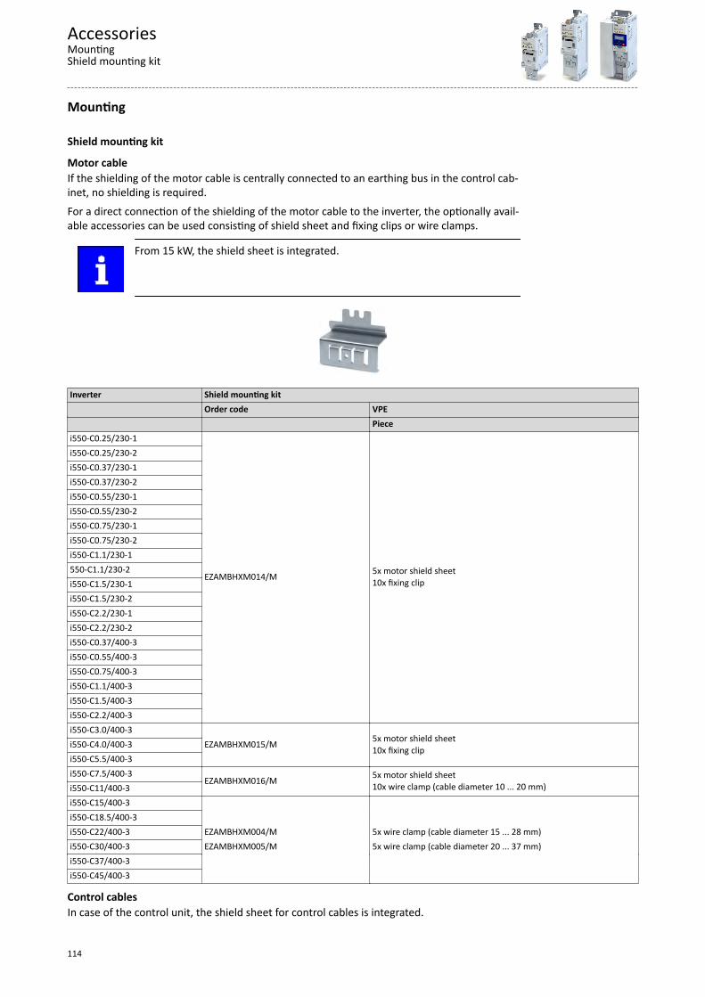
Mounting
Shield mounting kit
Motor cableIf the shielding of the motor cable is centrally connected to an earthing bus in the control cab-inet, no shielding is required.
For a direct connection of the shielding of the motor cable to the inverter, the optionally avail-able accessories can be used consisting of shield sheet and fixing clips or wire clamps.
From 15 kW, the shield sheet is integrated.
Inverter Shield mounting kit Order code VPE Piecei550-C0.25/230-1
EZAMBHXM014/M 5x motor shield sheet10x fixing clip
i550-C0.25/230-2i550-C0.37/230-1i550-C0.37/230-2i550-C0.55/230-1i550-C0.55/230-2i550-C0.75/230-1i550-C0.75/230-2i550-C1.1/230-1550-C1.1/230-2i550-C1.5/230-1i550-C1.5/230-2i550-C2.2/230-1i550-C2.2/230-2i550-C0.37/400-3i550-C0.55/400-3i550-C0.75/400-3i550-C1.1/400-3i550-C1.5/400-3i550-C2.2/400-3i550-C3.0/400-3
EZAMBHXM015/M 5x motor shield sheet10x fixing clipi550-C4.0/400-3
i550-C5.5/400-3i550-C7.5/400-3
EZAMBHXM016/M 5x motor shield sheet10x wire clamp (cable diameter 10 ... 20 mm)i550-C11/400-3
i550-C15/400-3 i550-C18.5/400-3 i550-C22/400-3 EZAMBHXM004/M 5x wire clamp (cable diameter 15 ... 28 mm)i550-C30/400-3 EZAMBHXM005/M 5x wire clamp (cable diameter 20 ... 37 mm)i550-C37/400-3 i550-C45/400-3
Control cablesIn case of the control unit, the shield sheet for control cables is integrated.
AccessoriesMountingShield mounting kit
114
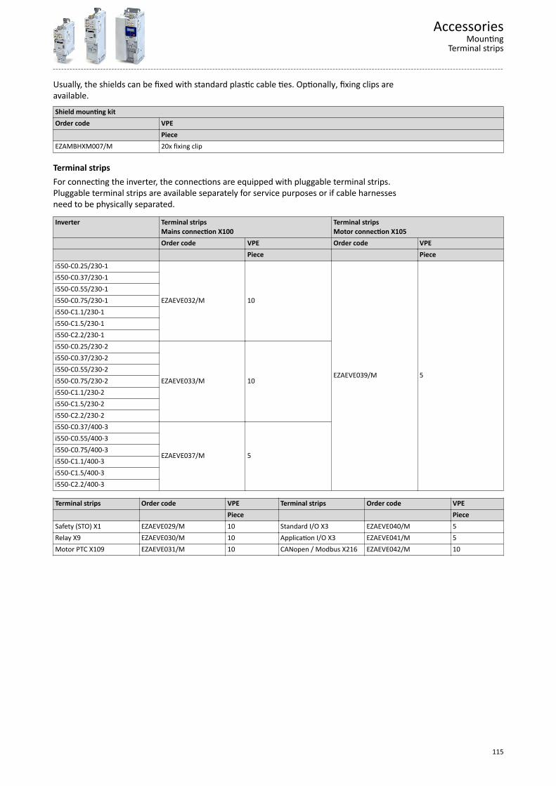
Usually, the shields can be fixed with standard plastic cable ties. Optionally, fixing clips areavailable.
Shield mounting kitOrder code VPE PieceEZAMBHXM007/M 20x fixing clip
Terminal stripsFor connecting the inverter, the connections are equipped with pluggable terminal strips.Pluggable terminal strips are available separately for service purposes or if cable harnessesneed to be physically separated.
Inverter Terminal stripsMains connection X100
Terminal stripsMotor connection X105
Order code VPE Order code VPE Piece Piecei550-C0.25/230-1
EZAEVE032/M 10
EZAEVE039/M 5
i550-C0.37/230-1i550-C0.55/230-1i550-C0.75/230-1i550-C1.1/230-1i550-C1.5/230-1i550-C2.2/230-1i550-C0.25/230-2
EZAEVE033/M 10
i550-C0.37/230-2i550-C0.55/230-2i550-C0.75/230-2i550-C1.1/230-2i550-C1.5/230-2i550-C2.2/230-2i550-C0.37/400-3
EZAEVE037/M 5
i550-C0.55/400-3i550-C0.75/400-3i550-C1.1/400-3i550-C1.5/400-3i550-C2.2/400-3
Terminal strips Order code VPE Terminal strips Order code VPE Piece PieceSafety (STO) X1 EZAEVE029/M 10 Standard I/O X3 EZAEVE040/M 5Relay X9 EZAEVE030/M 10 Application I/O X3 EZAEVE041/M 5Motor PTC X109 EZAEVE031/M 10 CANopen / Modbus X216 EZAEVE042/M 10
AccessoriesMounting
Terminal strips
115

Mounting/ installationMore data and information for the mechanical and electrical installation can be found here:• Control cabinet structure ^ 18• EMC-compliant installation ^ 20• Standards and operating conditions ^ 35• Dimensions ^ 69
The scope of supply of the inverter comprises mounting instructions. Theydescribe technical data and information on mechanical and electrical installa-tion.
Mounting position• Vertical alignment - all mains connections are at the top and the motor connections at thebottom.
Free spaces• Maintain the specified free spaces above and below to the other installations.
Mechanical installation• The mounting location and material must ensure a durable mechanical connection.• Do not mount onto DIN rails!• In case of continuous vibrations or shocks use vibration dampers.
How to mount the inverters onto the mounting plate1. Prepare mounting plate with corresponding threaded holes and equip them with screws
and, if required, washers.a) Use screw and washer assemblies or hexagon socket screws with washers.b)Do not yet tighten the screws.
2. Mount the inverter on the prepared mounting plate via keyhole suspension.3. Only tighten the screws hand-tight.4. If required, pre-assemble further units.5. Adjust the units.6. Screw the units onto the mounting plate.The inverters are ready for wiring.
Measures for cooling during operation• Ensure unimpeded ventilation of cooling air and outlet of exhaust air.• If the cooling air is polluted (fluff, (conductive) dust, soot, aggressive gases), take adequate
countermeasures.• Install filters.• Arrange for regular cleaning of the filters.
• If required, implement a separate air guide.
Screw and washer assemblies or hexagon socket screws with washers are recommended..
M5 x ≥ 10 mm for devices up to and including 2.2 kW
M5 x ≥ 12 mm for devices up to and including 11 kW
M6 x ≥ 16 mm for devices up to and including 22 kW
M8 x ≥ 16 mm for devices up to and including 45 kW
Mounting/ installation
116
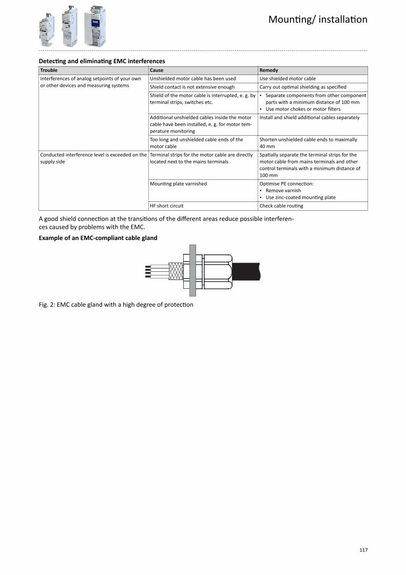
Detecting and eliminating EMC interferencesTrouble Cause RemedyInterferences of analog setpoints of your ownor other devices and measuring systems
Unshielded motor cable has been used Use shielded motor cableShield contact is not extensive enough Carry out optimal shielding as specifiedShield of the motor cable is interrupted, e. g. byterminal strips, switches etc.
• Separate components from other componentparts with a minimum distance of 100 mm
• Use motor chokes or motor filtersAdditional unshielded cables inside the motorcable have been installed, e. g. for motor tem-perature monitoring
Install and shield additional cables separately
Too long and unshielded cable ends of themotor cable
Shorten unshielded cable ends to maximally40 mm
Conducted interference level is exceeded on thesupply side
Terminal strips for the motor cable are directlylocated next to the mains terminals
Spatially separate the terminal strips for themotor cable from mains terminals and othercontrol terminals with a minimum distance of100 mm
Mounting plate varnished Optimise PE connection:• Remove varnish• Use zinc-coated mounting plate
HF short circuit Check cable routing
A good shield connection at the transitions of the different areas reduce possible interferen-ces caused by problems with the EMC.
Example of an EMC-compliant cable gland
Fig. 2: EMC cable gland with a high degree of protection
Mounting/ installation
117

Electrical installation
Important notes
DANGER!Dangerous electrical voltage
Depending on the device, all power connections may be live up to 3 minutes after switchingoff the supply.
Possible consequences: Death or severe injuries when touching the power terminals. Wait for at least 3 minutes before you start working on the power terminals. Make sure that all power terminals are deenergised.
DANGER!Dangerous electrical voltage
The leakage current against earth (PE) is > 3.5 mA AC or > 10 mA DC.
Possible consequences: Death or severe injuries when touching the device in the event of anerror. Implement the measures required in EN 61800-5-1, especially: Fixed installation The PE connection must comply with the standards (PE conductor diameter ≥ 10 mm2 or
use a double PE conductor)
NOTICENo device protection against too high mains voltage
The mains input is not fused internally.
Possible consequences: Destruction of the device at too high mains voltage. Please observe the maximum permissible mains voltage. Fuse the device professionally on the supply side against mains fluctuations and voltage
peaks.
DANGER!Use of the inverter on a phase earthed mains with a rated mains voltage ≥ 400 V
The protection against accidental contact is not ensured without external measures. If protection against accidental contact according to EN 61800-5-1 is required for the control
terminals of the inverters and the connections of the plugged device modules, ... an additional basic insulation has to be provided. the components to be connected have to come with a second basic insulation.
Mounting/ installationElectrical installationImportant notes
118

NOTICEOvervoltage at devices with 230-V mains connection
An impermissible overvoltage may occur if the central supply of the N conductor is interrup-ted if the devices are connected to a TN three-phase system.
Possible consequences: Destruction of the device Provide for the use of isolating transformers.
NOTICEThe product contains electrostatic sensitive devices.
Possible consequences: Destruction of the device Before working in the connection area, the staff must ensure to be free of electrostatic
charge.
NOTICEPluggable terminal strips or plug connections
Plugging or removing the terminal strips or plug connections during operation may cause highvoltages and arcing.
Possible consequences: Damage of the devices Switch off device. Only plug or remove the terminal strips or plug connections in deenergised status.
NOTICEUse of mains filters and RFI filters in IT systems
Mains filters and RFI filters from Lenze contain components that are interconnected againstPE.
Possible consequences: The filters may be destroyed when an earth fault occurs.
Possible consequences: Monitoring of the IT system may be triggered. Do not use mains filters and RFI filters from Lenze in IT systems. Before using the inverter in the IT system, remove the IT screws.
NOTICEOvervoltage at components
In case of an earth fault in IT systems, intolerable overvoltages may occur in the plant.
Possible consequences: Destruction of the device. Before using the inverter in the IT system, the contact screws must be removed. Positions and number of the contact screws depend on the device.
Ensure a trouble-free operation:
Carry out the total wiring so that the separation of the separate potential areasis preserved.
Mounting/ installationElectrical installation
Important notes
119

When implementing machines and systems for the use in the UL/CSA scope, youhave to observe especially issued notes.
These notes and further information on the UL/CSA subject are summarised inseparated documents.
You have to install the devices into housings (e. g. control cabinets) to complywith valid regulations.
Stickers with warning notes must be displayed prominently and close to thedevice.
Mounting/ installationElectrical installationImportant notes
120

Mains connectionThe following should be considered for the mains connection of inverters:
Single inverters are either directly connected to the AC system or via upstream filters. RFI fil-ters are already integrated in many inverters. Depending on the requirements, mains chokesor mains filters can be used.
Inverter groups are connected to the DC system with the DC bus. For this purpose, the inver-ters have to be provided with a connection for the DC bus, e. g. terminals +UG/-UG.
This enables the energy exchange in phases with operation in generator and motor mode ofseveral drives in the network.
The DC system can be provided by power supply modules (AC/DC converters) or inverters witha power reserve.
The technical data informs about the possible applications in the given groups. In the dimen-sioning, data and further notes have to be observed.
Mounting/ installationElectrical installation
Mains connection
121

1-phase mains connection 230/240 V
Connection planThe wiring diagram is valid for I5xAExxxB inverters.
X26
6
X26
7
EtherNet/IP
X25
6
X25
7
PROFINET
IN
OU
T
X24
6
X24
7
EtherCAT
IN
OU
T
X22
6
PROFIBUS
TB
CO
M
TA
X21
6
Modbus C
L C
G
CH
X
216
CANopen
Safe
ty S
TO
X1
SIA
G
S S
IB
DC 24 V SELV/PELV(+19.2 … +28.8 V)
"
1k ..
. 10k
0 ...
10
V
S1
DI3 DI4
100 mA
4.4k
+24 V +10 V
4.4k
4.4k
4.4k
4.4k
10 m
AStandard I/O
GN
D
DO
1
DI1
DI2
DI3
DI4
DI5
24E
GN
D
AI1
AI2
10V
GN
D
AO
1
24V
24E
X
3
24V
4.
4k D
I7
4.4k
AO
2 DI1
D
O2
GN
D
GN
D
DI6
Application I/O
X10
5 U
V
W
R
b1
Rb2
+ X10
9 T
1 T
2
" "
M3~+
JJ
NC
NO
CO
M
X9
AC 240 V3 A
F1…F3Q1
X10
0 L
1 L
2/N
2/PE AC 170 V ... 264 V45 Hz ... 65 Hz
+
2/PE AC 170 V ... 264 V45 Hz ... 65 Hz
+
F1…F2Q1
X10
0 L
1 L
2/N
X10
0 L
1 L
2/N
F1
Q1
PEN
L2L1
2/N/PE AC 208 V ... 240 V
PEN
L3L2L1
3/N/PE AC 208 V ... 240 V
PEN
L3L2L1
+
1/N/PEAC 170 V ... 264 V45 Hz ... 65 Hz
3/N/PE AC 400 V
Fig. 3: Wiring example
S1 Start/StopFx Fuses
Q1 Mains contactor--- Dashed line = options
Mounting/ installationElectrical installationMains connection
122
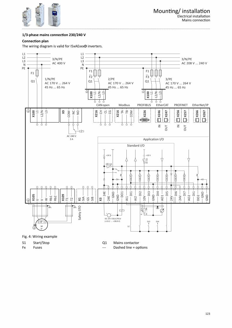
1/3-phase mains connection 230/240 V
Connection planThe wiring diagram is valid for I5xAExxxD inverters.
X26
6
X26
7
EtherNet/IP
X25
6
X25
7
PROFINET
IN
OU
T
X24
6
X24
7
EtherCAT
IN
OU
T
X22
6
PROFIBUS
TB
CO
M
TA
X21
6
Modbus C
L C
G
CH
X
216
CANopen
Safe
ty S
TO
X1
SIA
G
S S
IB
DC 24 V SELV/PELV(+19.2 … +28.8 V)
"
1k ..
. 10k
0 ...
10
V
S1
DI3 DI4
100 mA
4.4k
+24 V +10 V
4.4k
4.4k
4.4k
4.4k
10 m
AStandard I/O
GN
D
DO
1
DI1
DI2
DI3
DI4
DI5
24E
GN
D
AI1
AI2
10V
GN
D
AO
1
24V
24E
X
3
24V
4.
4k D
I7
4.4k
AO
2 DI1
D
O2
GN
D
GN
D
DI6
Application I/O
X10
5 U
V
W
R
b1
Rb2
+ X10
9 T
1 T
2
" "
M3~+
JJ
NC
NO
CO
M
X9
AC 240 V3 A
F1…F3Q1
X10
0 L
1 L
2/N
3/PE AC 170 V ... 264 V45 Hz ... 65 Hz
L3 +
2/PE AC 170 V ... 264 V45 Hz ... 65 Hz
+
F1…F2Q1
X10
0 L
1 L
2/N
L
3
X10
0 L
1 L
2/N
L
3
F1
Q1
PEN
L3L2L1
3/N/PE AC 208 V ... 240 V
PEN
L3L2L1
+
1/N/PEAC 170 V ... 264 V45 Hz ... 65 Hz
3/N/PE AC 400 V
Fig. 4: Wiring example
S1 Start/StopFx Fuses
Q1 Mains contactor--- Dashed line = options
Mounting/ installationElectrical installation
Mains connection
123

3-phase mains connection 230/240 V
Connection planThe connection plan is valid for the I5xAExxxC inverters.
X26
6
X26
7
EtherNet/IP
X25
6
X25
7
PROFINET
IN
OU
T
X24
6
X24
7
EtherCAT
IN
OU
T
X22
6
PROFIBUS
TB
CO
M
TA
X21
6
Modbus C
L C
G
CH
X
216
CANopen
Safe
ty S
TO
X1
SIA
G
S S
IB
DC 24 V SELV/PELV(+19.2 … +28.8 V)
"
1k ..
. 10k
0 ...
10
V
S1
DI3 DI4
100 mA
4.4k
+24 V +10 V
4.4k
4.4k
4.4k
4.4k
10 m
AStandard I/O
GN
D
DO
1
DI1
DI2
DI3
DI4
DI5
24E
GN
D
AI1
AI2
10V
GN
D
AO
1
24V
24E
X
3
24V
4.
4k D
I7
4.4k
AO
2 DI1
D
O2
GN
D
GN
D
DI6
Application I/O
X10
5 U
V
W
R
b1
Rb2
+ X10
9 T
1 T
2
" "
M3~+
JJ
NC
NO
CO
M
X9
AC 240 V3 A
X10
0 L
1 L
2 L
3 n
.c.
n.c
.
F1…F3Q1
3/N/PE AC 208 V ... 240 V
3/PE AC 170 V ... 264 V45 Hz ... 65 Hz
PEN
L3L2L1
+
Fig. 5: Wiring example
S1 Start/StopFx Fuses
Q1 Mains contactor--- Dashed line = options
Mounting/ installationElectrical installationMains connection
124

3-phase mains connection 400 V
Connection planThe wiring diagram is valid for I5xAExxxF inverters.
X26
6
X26
7
EtherNet/IP
X25
6
X25
7
PROFINET
IN
OU
T
X24
6
X24
7
EtherCAT
IN
OU
T
X22
6
PROFIBUS
TB
CO
M
TA
X21
6
Modbus C
L C
G
CH
X
216
CANopen
Safe
ty S
TO
X1
SIA
G
S S
IB
DC 24 V SELV/PELV(+19.2 … +28.8 V)
"
1k ..
. 10k
0 ...
10
V
S1
DI3 DI4
100 mA
4.4k
+24 V +10 V
4.4k
4.4k
4.4k
4.4k
10 m
AStandard I/O
GN
D
DO
1
DI1
DI2
DI3
DI4
DI5
24E
GN
D
AI1
AI2
10V
GN
D
AO
1
24V
24E
X
3
24V
4.
4k D
I7
4.4k
AO
2 DI1
D
O2
GN
D
GN
D
DI6
Application I/O
X10
5 U
V
W
R
b1
Rb2
+ X10
9 T
1 T
2
" "
M3~+
JJ
NC
NO
CO
M
X9
AC 240 V3 A
X10
0 L
1 L
2 L
3 +
UG
-U
G
F1…F3Q1
3/N/PE AC 400 V
3/PE AC 340 V ... 528 V45 Hz ... 65 Hz
PEN
L3L2L1
+
Fig. 6: Wiring example
S1 Start/StopFx Fuses
Q1 Mains contactor--- Dashed line = options
Mounting/ installationElectrical installation
Mains connection
125
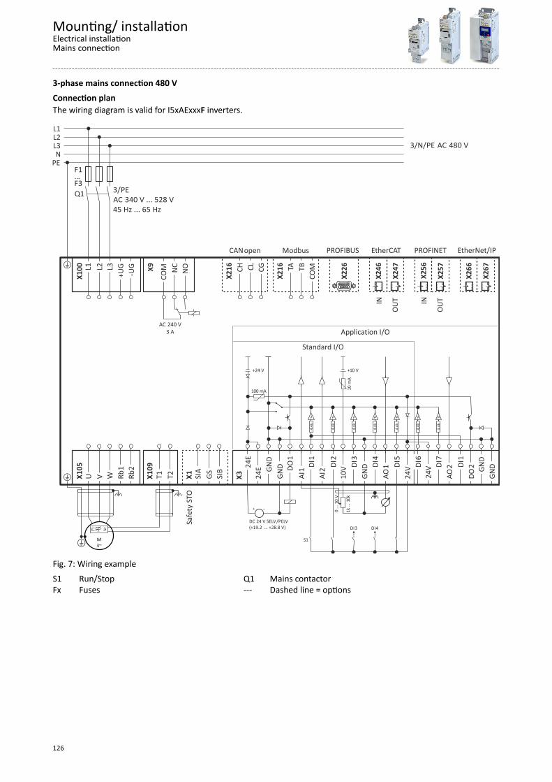
3-phase mains connection 480 V
Connection planThe wiring diagram is valid for I5xAExxxF inverters.
X26
6
X26
7
EtherNet/IP
X25
6
X25
7
PROFINET
IN
OU
T
X24
6
X24
7
EtherCAT
IN
OU
T
X22
6
PROFIBUS
TB
CO
M
TA
X21
6
Modbus C
L C
G
CH
X
216
CANopen
Safe
ty S
TO
X1
SIA
G
S S
IB
DC 24 V SELV/PELV(+19.2 … +28.8 V)
"
1k ..
. 10k
0 ...
10
V
S1
DI3 DI4
100 mA
4.4k
+24 V +10 V
4.4k
4.4k
4.4k
4.4k
10 m
AStandard I/O
GN
D
DO
1
DI1
DI2
DI3
DI4
DI5
24E
GN
D
AI1
AI2
10V
GN
D
AO
1
24V
24E
X
3
24V
4.
4k D
I7
4.4k
AO
2 DI1
D
O2
GN
D
GN
D
DI6
Application I/O
X10
5 U
V
W
R
b1
Rb2
+ X10
9 T
1 T
2
" "
M3~+
JJ
NC
NO
CO
M
X9
AC 240 V3 A
X10
0 L
1 L
2 L
3 +
UG
-U
G
F1…F3Q1
3/N/PE AC 480 V
3/PE AC 340 V ... 528 V45 Hz ... 65 Hz
PEN
L3L2L1
+
Fig. 7: Wiring example
S1 Run/StopFx Fuses
Q1 Mains contactor--- Dashed line = options
Mounting/ installationElectrical installationMains connection
126

Motor connectionA good shield connection and short cable lengths reduce possible interferences caused byproblems with the EMC.
Example for preparing the EMC-compliant wiring or the motor cablel
①
② ③
Fig. 8: Shield connection
① Braid② large surface contacting of the braid
③ Heat-shrinkable tubel maximally 500 mm
Switching in the motor cable
Switching on the motor side of the inverter is permissible:
For safety shutdown (emergency stop).
In case several motors are driven by one inverter (only in V/f operating mode).
Please note the following:
The switching elements on the motor side must be dimensioned for with themaximum occurring load.
Connection of motor temperature monitoring
If the terminal X109 is used, e. g. to connect an external PTC thermistor (PTC) ora thermal contact, ensure at least one basic insulation to the potentials ofmotor, mains and control terminals to not restrict the protective separation ofthe control terminals.
Mounting/ installationElectrical installation
Motor connection
127
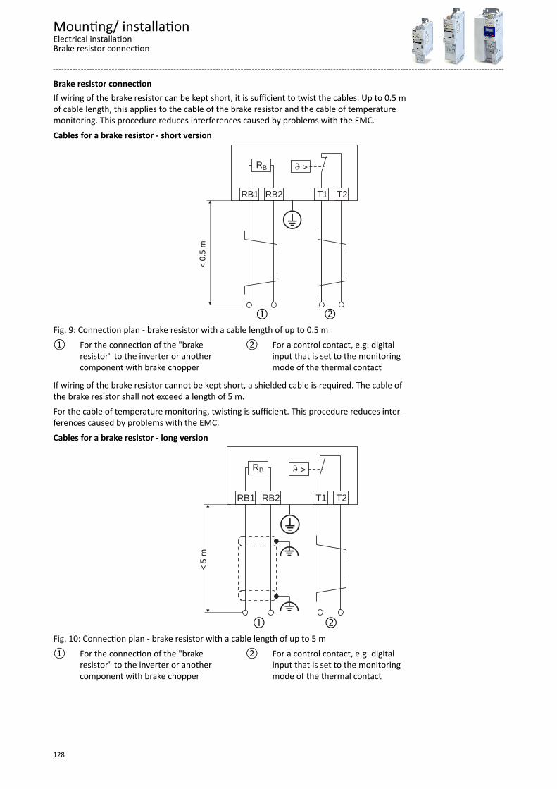
Brake resistor connectionIf wiring of the brake resistor can be kept short, it is sufficient to twist the cables. Up to 0.5 mof cable length, this applies to the cable of the brake resistor and the cable of temperaturemonitoring. This procedure reduces interferences caused by problems with the EMC.
Cables for a brake resistor - short version
RB
RB1 RB2<
0.5
mT1 T2
Fig. 9: Connection plan - brake resistor with a cable length of up to 0.5 m
① For the connection of the "brakeresistor" to the inverter or anothercomponent with brake chopper
② For a control contact, e.g. digitalinput that is set to the monitoringmode of the thermal contact
If wiring of the brake resistor cannot be kept short, a shielded cable is required. The cable ofthe brake resistor shall not exceed a length of 5 m.
For the cable of temperature monitoring, twisting is sufficient. This procedure reduces inter-ferences caused by problems with the EMC.
Cables for a brake resistor - long version
RB
RB1 RB2
< 5
m
T1 T2
Fig. 10: Connection plan - brake resistor with a cable length of up to 5 m
① For the connection of the "brakeresistor" to the inverter or anothercomponent with brake chopper
② For a control contact, e.g. digitalinput that is set to the monitoringmode of the thermal contact
Mounting/ installationElectrical installationBrake resistor connection
128

Control connections
In order to achieve an optimum shielding effect (in case of very long cables, withhigh interference), one shield end of analog input and output cables can be con-nected to PE potential via a capacitor (e. g. 10 nF/250 V).
Mounting/ installationElectrical installationControl connections
129

Purchase order
Notes on orderingThere are two ways to order an inverter.
As a complete inverter or as single components consisting of power unit, control unit andsafety module.
Complete inverter Inverter consisting of components
Control unit
Power unit
Safety module
Purchase orderNotes on ordering
130
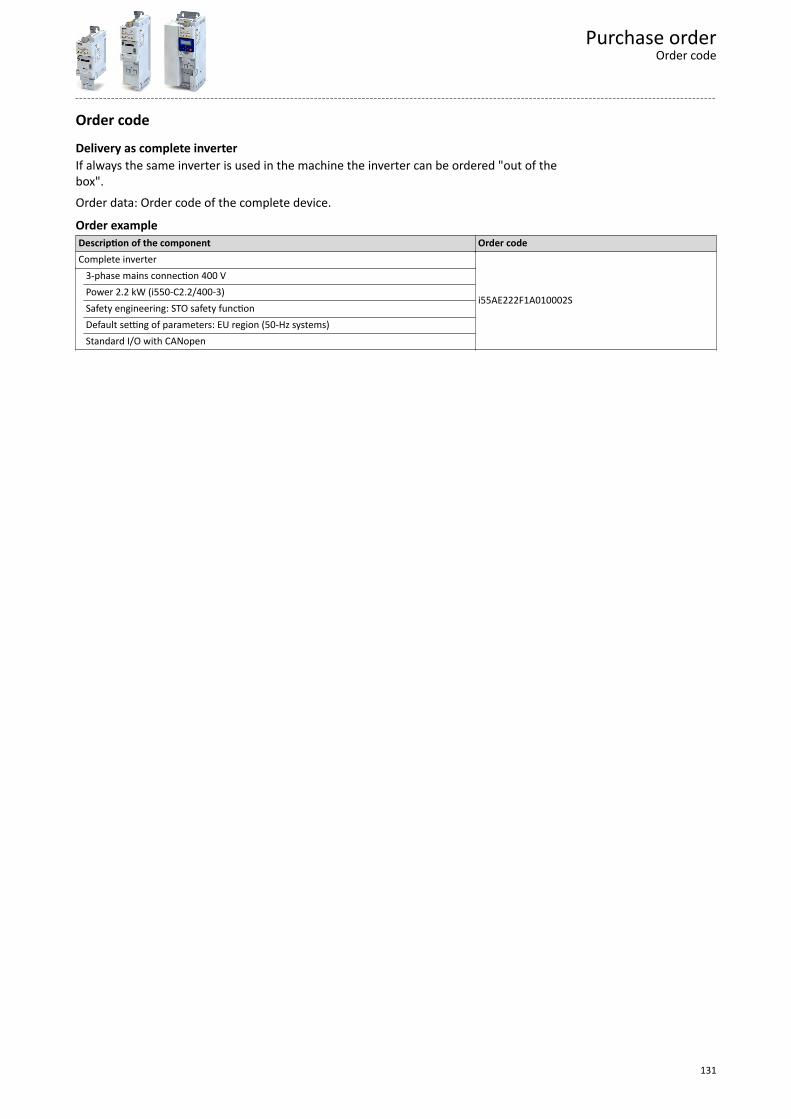
Order code
Delivery as complete inverterIf always the same inverter is used in the machine the inverter can be ordered "out of thebox".
Order data: Order code of the complete device.
Order exampleDescription of the component Order codeComplete inverter
i55AE222F1A010002S
3-phase mains connection 400 V Power 2.2 kW (i550-C2.2/400-3) Safety engineering: STO safety function Default setting of parameters: EU region (50-Hz systems) Standard I/O with CANopen
Purchase orderOrder code
131
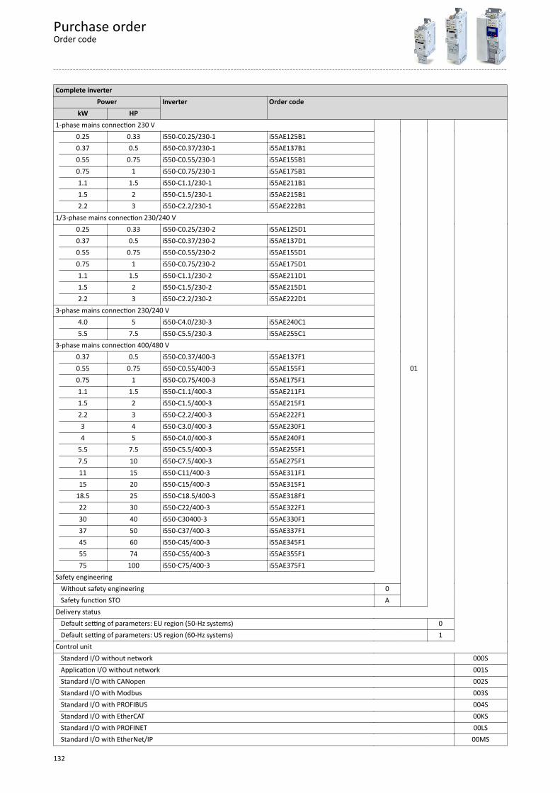
Complete inverterPower Inverter Order code
kW HP 1-phase mains connection 230 V 0.25 0.33 i550-C0.25/230-1 i55AE125B1
01
0.37 0.5 i550-C0.37/230-1 i55AE137B10.55 0.75 i550-C0.55/230-1 i55AE155B10.75 1 i550-C0.75/230-1 i55AE175B11.1 1.5 i550-C1.1/230-1 i55AE211B11.5 2 i550-C1.5/230-1 i55AE215B12.2 3 i550-C2.2/230-1 i55AE222B1
1/3-phase mains connection 230/240 V 0.25 0.33 i550-C0.25/230-2 i55AE125D1
0.37 0.5 i550-C0.37/230-2 i55AE137D10.55 0.75 i550-C0.55/230-2 i55AE155D10.75 1 i550-C0.75/230-2 i55AE175D11.1 1.5 i550-C1.1/230-2 i55AE211D11.5 2 i550-C1.5/230-2 i55AE215D12.2 3 i550-C2.2/230-2 i55AE222D1
3-phase mains connection 230/240 V 4.0 5 i550-C4.0/230-3 i55AE240C1 5.5 7.5 i550-C5.5/230-3 i55AE255C1 3-phase mains connection 400/480 V 0.37 0.5 i550-C0.37/400-3 i55AE137F1
0.55 0.75 i550-C0.55/400-3 i55AE155F10.75 1 i550-C0.75/400-3 i55AE175F11.1 1.5 i550-C1.1/400-3 i55AE211F11.5 2 i550-C1.5/400-3 i55AE215F12.2 3 i550-C2.2/400-3 i55AE222F13 4 i550-C3.0/400-3 i55AE230F14 5 i550-C4.0/400-3 i55AE240F1
5.5 7.5 i550-C5.5/400-3 i55AE255F17.5 10 i550-C7.5/400-3 i55AE275F111 15 i550-C11/400-3 i55AE311F115 20 i550-C15/400-3 i55AE315F1
18.5 25 i550-C18.5/400-3 i55AE318F122 30 i550-C22/400-3 i55AE322F130 40 i550-C30400-3 i55AE330F137 50 i550-C37/400-3 i55AE337F145 60 i550-C45/400-3 i55AE345F155 74 i550-C55/400-3 i55AE355F175 100 i550-C75/400-3 i55AE375F1
Safety engineering Without safety engineering 0
Safety function STO A Delivery status Default setting of parameters: EU region (50-Hz systems) 0
Default setting of parameters: US region (60-Hz systems) 1 Control unit Standard I/O without network 000SApplication I/O without network 001SStandard I/O with CANopen 002SStandard I/O with Modbus 003SStandard I/O with PROFIBUS 004SStandard I/O with EtherCAT 00KSStandard I/O with PROFINET 00LSStandard I/O with EtherNet/IP 00MS
Purchase orderOrder code
132
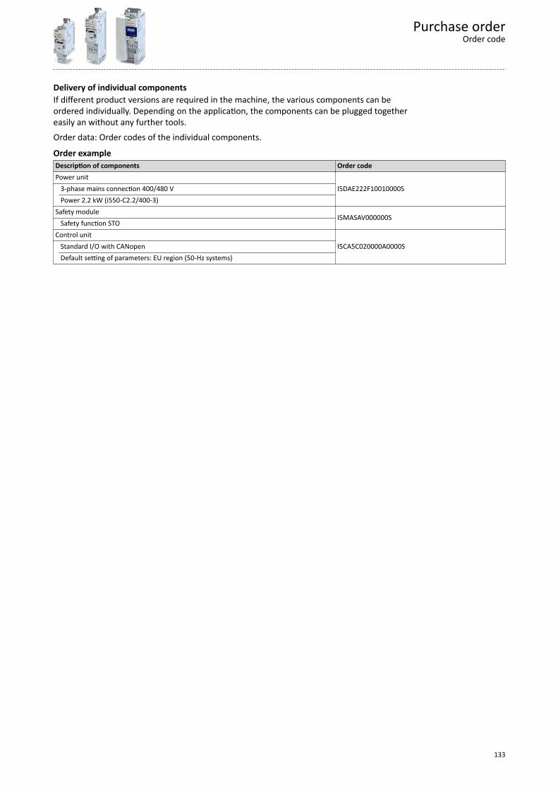
Delivery of individual componentsIf different product versions are required in the machine, the various components can beordered individually. Depending on the application, the components can be plugged togethereasily an without any further tools.
Order data: Order codes of the individual components.
Order exampleDescription of components Order codePower unit
I5DAE222F10010000S 3-phase mains connection 400/480 V Power 2.2 kW (i550-C2.2/400-3)Safety module
I5MASAV000000S Safety function STOControl unit
I5CA5C020000A0000S Standard I/O with CANopen Default setting of parameters: EU region (50-Hz systems)
Purchase orderOrder code
133

Power unitPower Inverter Order code
kW HP 1-phase mains connection 230 V 0.25 0.33 i550-C0.25/230-1 I5DAE125B10010000S
0.37 0.5 i550-C0.37/230-1 I5DAE137B10010000S0.55 0.75 i550-C0.55/230-1 I5DAE155B10010000S0.75 1 i550-C0.75/230-1 I5DAE175B10010000S1.1 1.5 i550-C1.1/230-1 I5DAE211B10010000S1.5 2 i550-C1.5/230-1 I5DAE215B10010000S2.2 3 i550-C2.2/230-1 I5DAE222B10010000S
1/3-phase mains connection 230/240 V 0.25 0.33 i550-C0.25/230-2 I5DAE125D10000000S
0.37 0.5 i550-C0.37/230-2 I5DAE137D10000000S0.55 0.75 i550-C0.55/230-2 I5DAE155D10000000S0.75 1 i550-C0.75/230-2 I5DAE175D10000000S1.1 1.5 i550-C1.1/230-2 I5DAE211D10000000S1.5 2 i550-C1.5/230-2 I5DAE215D10000000S2.2 3 i550-C2.2/230-2 I5DAE222D10000000S
3-phase mains connection 230/240 V 4.0 5 i550-C4.0/230-3 I5DAE240C10010000S 5.5 7.5 i550-C5.5/230-3 I5DAE255C10010000S3-phase mains connection 400/480 V 0.37 0.5 i550-C0.37/400-3 I5DAE137F10010000S
0.55 0.75 i550-C0.55/400-3 I5DAE155F10010000S0.75 1 i550-C0.75/400-3 I5DAE175F10010000S1.1 1.5 i550-C1.1/400-3 I5DAE211F10010000S1.5 2 i550-C1.5/400-3 I5DAE215F10010000S2.2 3 i550-C2.2/400-3 I5DAE222F10010000S3 4 i550-C3.0/400-3 I5DAE230F10010000S4 5 i550-C4.0/400-3 I5DAE240F10010000S
5.5 7.5 i550-C5.5/400-3 I5DAE255F10010000S7.5 10 i550-C7.5/400-3 I5DAE275F10010000S11 15 i550-C11/400-3 I5DAE311F10010000S15 20 i550-C15/400-3 I5DAE315F10010000S
18.5 25 i550-C18.5/400-3 I5DAE318F10010000S22 30 i550-C22/400-3 I5DAE322F10010000S30 40 i550-C30/400-3 I5DAE330F10010000S37 50 i550-C37/400-3 I5DAE337F10010000S45 60 i550-C45/400-3 I5DAE345F10010000S
55 74 i550-C55/400-3 I5DAE355F10010000S 75 100 i550-C55/400-3 I5DAE375F10010000S
Safety module Order code Safety function STO I5MASAV000000S
Purchase orderOrder code
134

Control unit Order code Delivery status
Default setting of parameters: EU region (50-Hz sys-tems)
Delivery statusDefault setting of parameters: US region (60-Hz sys-tems)
Standard I/O without network I5CA50020000A0000S I5CA50020000A1000S Application I/O without network I5CA50030000A0000S I5CA50030000A1000S Standard I/O with CANopen I5CA5C020000A0000S I5CA5C020000A1000S Standard I/O with Modbus I5CA5W020000A0000S I5CA5W020000A1000S Standard I/O with PROFIBUS I5CA5P020000A0000S I5CA5P020000A1000S Standard I/O with EtherCAT I5CA5T020000A0000S I5CA5T020000A1000S Standard I/O with PROFINET I5CA5R020000A0000S I5CA5R020000A1000S Standard I/O with EtherNet/IP i5CA5G020000A0000S I5CA5G020000A1000S
Purchase orderOrder code
135

Appendix
Good to know
Approvals/directivesCCC China Compulsory Certification
documents the compliance with the legal product safety requirements of the PR of China - GB standards.
CCSAUS CSA certificate, tested according to US and Canada standards
CE Communauté Européennedocuments the declaration of the manufacturer that EC Directives are complied with.
CEL China Energy Labeldocuments the compliance with the legal energy efficiency requirements for motors, tested according to PR of China standards
CSA Canadian Standards AssociationCSA certificate, tested according to Canada standards
ULEnergyUS CA
Energy Verified CertificateDetermining the energy efficiency according to CSA C390 for products within the scope of energy efficiency requirements in theUSA and Canada
CULUS UL certificatefor products, tested according to US and Canada standards
CURUS UL certificatefor components, tested according to US and Canada standards
EAC Customs union Russia / Belarus / Kazakhstan certificatedocuments the declaration of the manufacturer that the specifications for the Eurasian conformity (EAC) required for placingelectronic and electromechanical products on the market of the entire territory of the Customs Union (Russia, Belarus, Kazakh-stan) are complied with.
UL Underwriters Laboratory Listed ProductUR UL certificate
for components, tested according to US standards
AppendixGood to knowApprovals/directives
136

Operating modes of the motorOperating modes S1 ... S10 as specified by EN 60034-1 describe the basic stress of an electricalmachine.
In continuous operation a motor reaches its permissible temperature limit if it outputs therated power dimensioned for continuous operation. However, if the motor is only subjected toload for a short time, the power output by the motor may be greater without the motorreaching its permissible temperature limit. This behaviour is referred to as overload capacity.
Depending on the duration of the load and the resulting temperature rise, the required motorcan be selected reduced by the overload capacity.
The most important operating modesContinuous operation S1 Short-time operation S2
P
PVt
t
t
P
PVt
t
t
tB
Operation with a constant load until the motor reaches the thermalsteady state. The motor may be actuated continuously with its ratedpower.
Operation with constant load; however, the motor does not reach thethermal steady state. During the following standstill, the motor windingcools down to the ambient temperature again. The increase in powerdepends on the load duration.
Intermittent operation S3 Non-intermittent periodic operation S6
P
PVt
t
t
tS
tL tB
P
PVt
t
t
tS
tL tB
Sequence of identical duty cycles comprising operation with a constantload and subsequent standstill. Start-up and braking processes do nothave an impact on the winding temperature. The steady-state is notreached. The guide values apply to a cycle duration of 10 minutes. Thepower increase depends on the cycle duration and on the load period/downtime ratio.
Sequence of identical duty cycles comprising operation with a constantload and subsequent no-load operation. The motor cools down duringthe no-load phase. Start-up and braking processes do not have animpact on the winding temperature. The steady-state is not reached. Theguide values apply to a cycle duration of 10 minutes. The power increasedepends on the cycle duration and on the load period/idle time ratio.
P Power PV Power loss
t Time tB Load period
tL Idle time tS Cycle duration
ϑ Temperature
AppendixGood to know
Operating modes of the motor
137
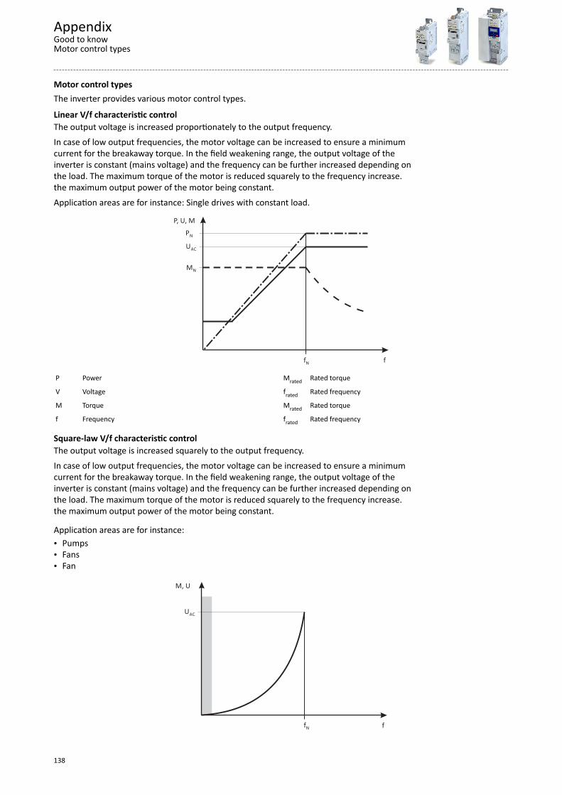
Motor control typesThe inverter provides various motor control types.
Linear V/f characteristic controlThe output voltage is increased proportionately to the output frequency.
In case of low output frequencies, the motor voltage can be increased to ensure a minimumcurrent for the breakaway torque. In the field weakening range, the output voltage of theinverter is constant (mains voltage) and the frequency can be further increased depending onthe load. The maximum torque of the motor is reduced squarely to the frequency increase.the maximum output power of the motor being constant.
Application areas are for instance: Single drives with constant load.
fN f
P, U, M
MN
UAC
PN
P Power Mrated Rated torque
V Voltage frated Rated frequency
M Torque Mrated Rated torque
f Frequency frated Rated frequency
Square-law V/f characteristic controlThe output voltage is increased squarely to the output frequency.
In case of low output frequencies, the motor voltage can be increased to ensure a minimumcurrent for the breakaway torque. In the field weakening range, the output voltage of theinverter is constant (mains voltage) and the frequency can be further increased depending onthe load. The maximum torque of the motor is reduced squarely to the frequency increase.the maximum output power of the motor being constant.
Application areas are for instance:• Pumps• Fans• Fan
f
M, U
UAC
fN
AppendixGood to knowMotor control types
138
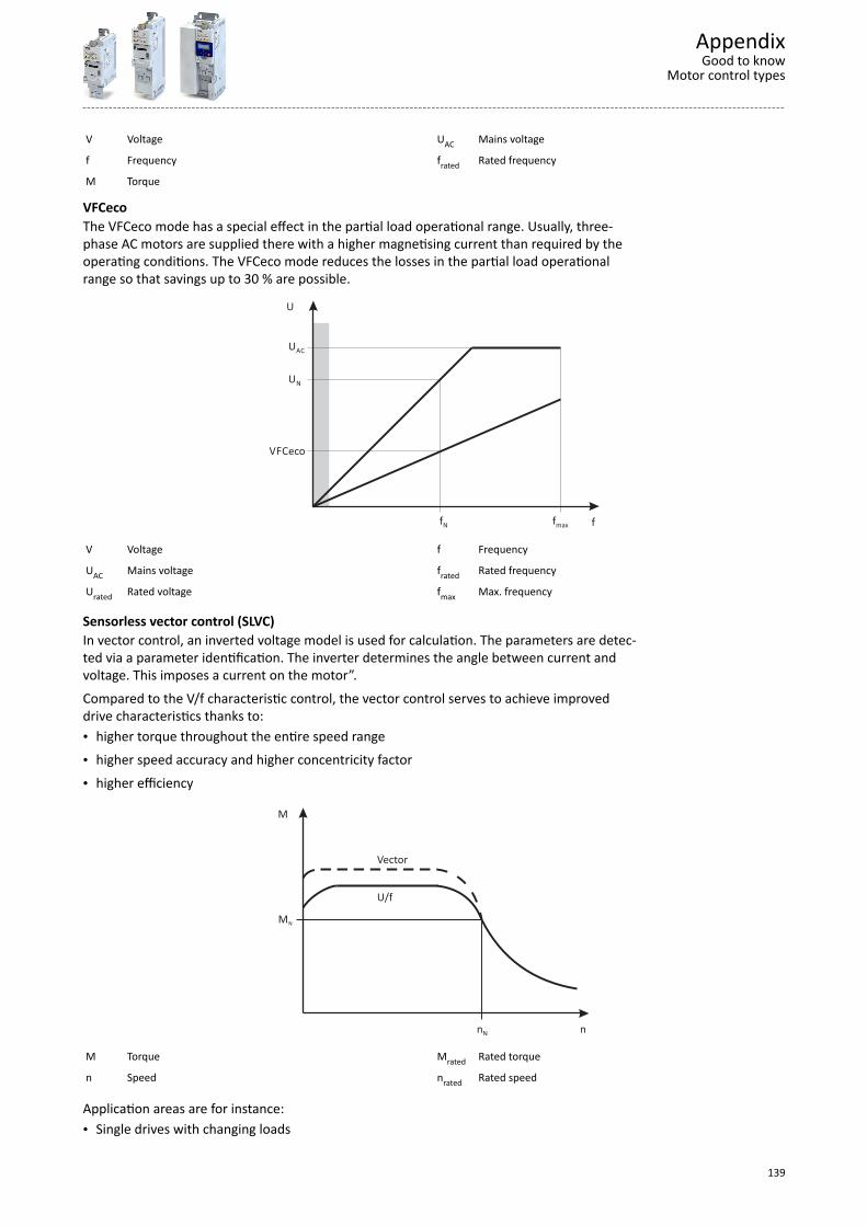
V Voltage UAC Mains voltage
f Frequency frated Rated frequency
M Torque
VFCecoThe VFCeco mode has a special effect in the partial load operational range. Usually, three-phase AC motors are supplied there with a higher magnetising current than required by theoperating conditions. The VFCeco mode reduces the losses in the partial load operationalrange so that savings up to 30 % are possible.
f
U
UN
UAC
fN fmax
VFCeco
V Voltage f Frequency
UAC Mains voltage frated Rated frequency
Urated Rated voltage fmax Max. frequency
Sensorless vector control (SLVC)In vector control, an inverted voltage model is used for calculation. The parameters are detec-ted via a parameter identification. The inverter determines the angle between current andvoltage. This imposes a current on the motor”.
Compared to the V/f characteristic control, the vector control serves to achieve improveddrive characteristics thanks to:• higher torque throughout the entire speed range
• higher speed accuracy and higher concentricity factor
• higher efficiency
nN n
M
MN
U/f
Vector
M Torque Mrated Rated torque
n Speed nrated Rated speed
Application areas are for instance:• Single drives with changing loads
AppendixGood to know
Motor control types
139

• Single drives with high starting duty
• Sensorless speed control of three-phase AC motors
Switching frequenciesOn an inverter, the term "switching frequency" is understood to mean the frequency withwhich the input and outputs of the output module (inverter) are switched. On an inverter, theswitching frequency can generally be set to values between 2 and 16 kHz, whereby the selec-tion is based on the respective power output
As switching the modules cause heat losses, the inverter can provide higher output currents atlow switching frequencies than at high frequencies. Additionally, it is distinguished betweenthe operation at a permanently set switching frequency and a variably set switching fre-quency. Here, the switching frequency is automatically reduced as a function of the deviceutilisation.
At a higher switching frequency, the noise generation is less.
Features VersionsSwitching frequencies • 2 kHz
• 4 kHz• 8 kHz• 16 kHz• variable (automatic adjustment)
EnclosuresThe degree of protection indicates the suitability of a motor for specific ambient conditionswith regard to humidity as well as the protection against contact and the ingress of foreignparticles. The degrees of protection are classified by EN 60529.
The first code number after the code letters IP indicates the protection against the ingress offoreign particles and dust.The second code number refers to the protection against the ingressof humidity.
Code number 1 Degree of protection Code number 2 Degree of protection0 No protection 0 No protection1 Protection against the ingress of foreign particles d >
50 mm. No protection in case of deliberate access.1 Protection against vertically dripping water (dripping
water).2 Protection against medium-sized foreign particles,
d > 12 mm, keeping away fingers or similar.2 Protection against diagonally falling water (dripping
water), 15 ° compared to normal service position.3 Protection against small foreign particles d > 2.5 mm.
Keeping away tools, wires or similar.3 Protection against spraying water, up to 60 ° to the ver-
tical4 Protection against granular foreign particles, d > 1 mm,
keeping away tools, wire or similar.4 Protection against spraying water from all directions.
5 Protection against dust deposits (dust-protected), com-plete protection against contact.
5 Protection against water jets from all directions.
6 Protection against the ingress of dust (dust-proof),complete protection against contact.
6 Protection against choppy seas or heavy water jets(flood protection).
AppendixGood to knowSwitching frequencies
140

Ö Lenze Drives GmbH Postfach 10 13 52, D-31763 Hameln Breslauer Straße 3, D-32699 Extertal Germany HR Lemgo B 6478Ü +49 5154 82-0Ø +49 5154 82-2800Ù [email protected]Ú www.lenze.com Û Lenze Service GmbH Breslauer Straße 3, D-32699 Extertal GermanyÜ 0080002446877 (24 h helpline)Ø +49 5154 82-1112Ù [email protected]
TD 20160801
© 08/2016 | 13519824 | 3.0


