Investigation of two-beam-pumpednoncollinear optical parametric
chirped-pulse amplification for thegeneration of few-cycle light pulses
Daniel Herrmann,1,2,3,4∗ Raphael Tautz,1,2,3,5 Franz Tavella,6
Ferenc Krausz,2,3 and Laszlo Veisz2
1 These two authors contributed equally to this work.2 Max-Planck-Institut fur Quantenoptik, Hans-Kopfermann-Strasse 1, 85748 Garching3 Department fur Physik, Ludwig-Maximilians-Universitat Munchen, Am Coulombwall 1,
Ludwig-Maximilians-Universitat, Oettingenstrasse 67, 80538 Munchen, Germany5 Present address: Photonics and Optoelectronics Group, Department of Physics and Center
Abstract: We demonstrate a new and compact φ -plane-pumped non-collinear optical parametric chirped-pulse amplification (NOPCPA) schemefor broadband pulse amplification, which is based on two-beam-pumping(TBP) at 532 nm. We employ type-I phase-matching in a 5 mm long BBOcrystal with moderate pump intensities to preserve the temporal pulsecontrast. Amplification and compression of the signal pulse from 675nm - 970 nm is demonstrated, which results in the generation of 7.1-fslight pulses containing 0.35 mJ energy. In this context, we investigate thepump-to-signal energy conversion efficiency for TBP-NOPCPA and outlinedetails for few-cycle pulse characterization. Furthermore, it is verified,that the interference at the intersection of the two pump beams does notdegrade the signal beam spatial profile. It is theoretically shown that theaccumulated OPA phase partially compensates for wave-vector mismatchand leads to extended broadband amplification. The experimental outcomeis supported by numerical split-step simulations of the parametric signalgain, including pump depletion and parametric fluorescence.
References and links1. D. Polli, M. R. Antognazza, D. Brida, G. Lanzani, G. Cerullo, and S. De Silvestri, “Broadband pump-probe spec-
troscopy with sub-10-fs resolution for probing ultrafast internal conversion and coherent phonons in carotenoids,”Chem. Phys. 350, 45-55 (2008).
2. T. Brabec and F. Krausz, “Intense few-cycle laser fields: Frontiers of nonlinear optics,” Rev. Mod. Phys. 72,545-591 (2000).
3. F. Krausz and M. Ivanov, “Attosecond physics,” Rev. Mod. Phys. 81, 163-234 (2009).
#119138 - $15.00 USD Received 27 Oct 2009; revised 23 Dec 2009; accepted 7 Jan 2010; published 17 Feb 2010
(C) 2010 OSA 1 March 2010 / Vol. 18, No. 5 / OPTICS EXPRESS 4170
4. K. Schmid, L. Veisz, F. Tavella, S. Benavides, R. Tautz, D. Herrmann, A. Buck, B. Hidding, A. Marcinkevicius,U. Schramm, M. Geissler, J. Meyer-ter-Vehn, D. Habs, and F. Krausz, “Few-Cycle Laser-Driven Electron Accel-eration,” Phys. Rev. Lett. 102, 124801 (2009).
5. G. D. Tsakiris, K. Eidmann, J. Meyer-ter-Vehn, and F. Krausz, “Route to intense single attosecond pulses,” NewJ. Phys. 8 (2006) 19.
6. A. Baltuska, Th. Udem, M. Uiberacker, M. Hentschel, E. Goulielmakis, Ch. Gohle, R. Holzwarth, V. S. Yakolev,A. Scrinzi, T. W. Hansch, and F. Krausz, “Attosecond control of electronic processes by intense light fields,”Nature 421, 611-615 (2003).
7. R. Horlein, Y. Nomura, D. Herrmann, M. Stafe, I. B. Foldes, S. G. Rykovanov, F. Tavella, A. Marcinkevicius, F.Krausz, L. Veisz, and G. D. Tsakiris, “Few-cycle harmonic emission from solid density plasmas,” (in prepara-tion).
8. A. Dubietis, G. Jonusauskas, and A. Piskarskas, “Powerful femtosecond pulse generation by chirped andstretched pulse parametric amplification in BBO crystal,” Opt. Commun. 88, 437-440 (1992).
9. I. N. Ross, P. Matousek, G. H. C. New, and K. Osvay, “Analysis and optimization of optical parametric chirpedpulse amplification,” J. Opt. Soc. Am. B 19, 2945-2956 (2002).
10. A. Dubietis, R. Butkus, and A. Piskarskas, “Trends in chirped pulse optical parametric amplification,” IEEE J.Sel. Top. Quantum Electron. 12, 163-172 (2006).
11. S. Witte, R. T. Zinkstok, A. L. Wolf, W. Hogervorst, W. Ubachs, and K. S. E. Eikema, “A source of 2 terawatt,2.7 cycle laser pulses based on noncollinear optical parametric chirped pulse amplification,” Opt. Express 14,8168-8177 (2006).
12. F. Tavella, Y. Nomura, L. Veisz, V. Pervak, A. Marcinkevicius, and F. Krausz, “Dispersion management for asub-10-fs, 10 TW optical parametric chirped-pulse amplifier,” Opt. Lett. 32, 2227-2229 (2007).
13. D. Herrmann, L. Veisz, R. Tautz, F. Tavella, K. Schmid, V. Pervak, and F. Krausz, ”Generation of sub-three-cycle, 16 TW light pulses by using noncollinear optical parametric chirped-pulse amplification,” Opt. Lett. 34,2459-2461 (2009).
14. A. Dubietis, R. Danielius, G. Tamosauskas, and A. Pisarskas, “Combining effect in a multiple-beam-pumpedoptical parametric amplifier,” J. Opt. Soc. Am. B 15, 1135-1139 (1998).
15. A. Marcinkevicius, A. Piskarskas, V. Smilgevicius, and A. Stabinis, “Parametric superfluorescence excited in anonlinear crystal by two uncorrelated pump beams,” Opt. Commun. 158, 101-104 (1998).
16. D. Brida, G. Cirmi, C. Manzoni, S. Bonora, P. Villoresi, S. De Silvestri, and G. Cerulo, “Sub-two-cycle lightpulses at 1.6μm from an optical parametric amplifier”, Opt. Lett. 33, 741-743 (2008).
17. T. S. Sosnowski, P. B. Stephens, and T. B. Norris, “Production of 30-fs pulses tunable throughout the visibleregion by a new technique in optical parametric amplification,” Opt. Lett. 21, 140-142 (1996).
18. E. Zeromskis, A. Dubietis, G. Tamosauskas, A. Piskarskas, ”Gain bandwidth broadening of continuum-seededoptical parametric amplifier by use of two pump beams,” Opt. Comm. 203, 435-440 (2002).
19. G. Tamosauskas, A. Dubietis, G. Valiulis, and A. Piskarskas, “Optical parametric amplifier pumped by twomutually incoherent laser beams,” Appl. Phys. B 91, 305307 (2008).
20. C. Wang, Y. Leng, B. Zhao, Z. Zhang, Z. Xu, “Extremely broad gain spectra of two-beam-pumped optical para-metric chirped-pulse amplifier,” Opt. Commun. 237, 169-177 (2004).
21. R. L. Sutherland, 1996, Handbook of Nonlinear Optics (Marcel Dekker, New York).22. G. Cerullo and S. de Silvestri, “Ultrafast optical parametric amplifiers,” Rev. of Sci. Instr. 74, 1-18 (2003).23. V. G. Dmitriev, G. G. Gurzadyan, and D. N. Nikogosyan, Handbook of Nonlinear Optical Crystals (Springer,
New York).24. J. A. Armstrong, N. Bloembergen, J. Ducuing, and P. S. Pershan, “Interactions between light waves in a nonlinear
dielectric,” Phys. Rev. 127, 1918-1939 (1962).25. R. A. Baumgartner and R. L. Byer, “Optical Parametric Amplification,” IEEE J. of. Quant. Electr. QE-15, 432-
444 (1979).26. F. Tavella, A. Marcinkevicius, and F. Krausz, “Investigation of the superfluorescence and signal amplification in
an ultrabroadband multiterawatt optical parametric chirped pulse amplifier system,” New J. Phys. 8 (2006) 219.27. A. Dement’ev, O. Vrublevskaja, V. Girdauskas, and R. Kazragyte, “Numerical Analysis of Short Pulse Optical
Parametric Amplification Using Type I Phase Matching,” Nonl. Anal.: Modelling and Control 9, 39-53 (2004).28. A. Kurtinaitis, A. Dementjev, and F. Ivanauskas, “Modeling of Pulse Propagation factor Changes in Type II
Second-Harmonic Generation,” Nonl. Anal.: Modelling an Control 6, 51-69 (2001).29. G. A. Reider, 1997, Photonik (Springer, New York).30. L. Hongjun, Z. Wei, C. Guofu, W. Yishan, C. Zhao, and R. Chi, “Investigation of spectral bandwidth of optical
parametric amplification,” Appl. Phys. B 79, 569576 (2004).31. F. Tavella, K. Schmid, N. Ishii, A. Marcinkevicius, L. Veisz, and F. Krausz, “High-dynamic range pulse-contrast
measurements of a broadband optical parametric chirped-pulse amplifier,” Appl. Phys. B 3, 753 (2005).32. G. Arisholm, “General numerical methods for simulating second-order nonlinear interactions in birefringent
media,” J. Opt. Soc. Am. B 14, 2543-2549 (1997).33. S. Witte, R. T. Zinkstok, W. Hogervorst, and K. S. E. Eikema, “Numerical simulation for performance optimiza-
tion of a few-cycle terawatt NOPCPA system,” Appl. Phys. B 87, 677684 (2007).
#119138 - $15.00 USD Received 27 Oct 2009; revised 23 Dec 2009; accepted 7 Jan 2010; published 17 Feb 2010
(C) 2010 OSA 1 March 2010 / Vol. 18, No. 5 / OPTICS EXPRESS 4171
34. A. Picozzi and M. Haeltermann, “Influence of walk-off, dispersion, and diffraction on the coherence of parametricfluorescence,” Phys. Rev. E, 63, 056611-1 - 056611-11 (2001).
35. A. Gatti, H. Wiedemann, L. A. Lugitao, and I- Marzoli, “Langevin treatment of quentum fluctuations and opticalpatterns in optical parametric oscillators below threshold,” Phys. Rev. A, 56, 877-897 (1997).
36. D. A. Kleinmann, “Theory of Optical Parametric Noise,” Phys. Rev., 174, 1027-1041 (1968).37. F. Salin, P. Georges, G. Roger, and A. Brun, “Single-shot measurement of a 52-fs pulse,” Applied Optics 26,
4528-4531 (1987).38. A. Brun, P. Georges, G. Le Saux, and F. Salin, “Single-shot characterization of ultrashort light pulses,” J. Phys.
D: Appl. Phys. 24, 1225-1233 (1991).39. H. Mashiko, A. Suda, and K. Midorikawa, “All-reflective interferometric autocorrelator for the measurement of
ultra-short optical pulses,” Appl. Phys. B 76, 525-530 (2003).40. R. Trebino, 2000, Frequency-Resolved Optical Gating: The Measurement of Ultrashort Laser Pulses (Kluwer
Academic Publishers, Norwell, USA).
1. Introduction
Light pulses with duration of only a few optical cycles open up novel parameter regimes fora number of applications, ranging from time-resolved optical spectroscopy to high-field sci-ence [1, 2]. Progress in strong-field physics such as attosecond science [3] or laser-based par-ticle acceleration [4] depend on the availability of suitable laser systems. Phase-controlled, in-tense, high-contrast, few-cycle light pulses can be used to generate powerful isolated attosecondpulses in the XUV range [5]. For this purpose, carrier-envelope phase effects with few-cyclepulses have been demonstrated [6, 7].
The invention of OPCPA offered the prospect of generating few-cycle laser pulses by pro-viding sufficient gain and gain-bandwidth to approach the terawatt level [8, 9]. NOPCPA of-fers many advantages over chirped pulse amplifiers (CPA), such as a broad gain-bandwidth,high single-pass gain, wavelength tunability and low thermal effects [10]. Due to many chal-lenges, amplification and compression of few-cycle, terawatt-class pulses have only recentlybeen demonstrated in the near-infrared [11, 12, 13]. Few-cycle NOPCPA systems require accu-rate dispersion control during stretching and compression over a broad bandwidth, along withoptimum phase-matching conditions, and a high quality picosecond pump laser. This is neededto achieve an efficient conversion, to ensure a good spatial signal profile and to provide a hightemporal pulse contrast. It was shown, that one can minimize optical parametric fluorescence(OPF) and reach a high pulse contrast suitable for high-field physics via moderately pumpedNOPCPA in combination with a strong seed in 5 mm long BBO type-I phase-matching [13].OPCPA and OPA allow for the use of multiple pump beams, which is an important but so farunexploited feature for laser systems [10]. The reason for this promising attribute is, that therelative pump phases are not important and no interferometric phase alignment is needed sincethe phase difference between the signal and the pump pulses are taken away by the idler pulse,hence compensating for random differences between them [14, 15]. Neighboring spectral re-gions of the seed can be amplified by using multiple pump beams in individual phase-matchinggeometry. Thus, a broader amplified signal spectrum can be achieved compared to employ-ing just one pump beam. TBP can also increase the repetition rate for high-power OPCPAsystems. Alternative approaches to TBP-NOPCPA for the generation of 1-3 cycle pulses areone-beam-pumping (OBP) collinear OPCPA at degeneracy and cascaded NOPCPA employingangular detuning [16, 17]. Previous TBP experimental studies were exclusively done on nar-rowband NOPCPA without revealing all characteristics like conversion efficiency, broadbandsignal spectra, broadband signal compressibility, pump beam interference, signal beam qualityand simulated gain (based on five nonlinear coupled wave equations including pump depletionand OPF) at the same time [14, 18, 19]. Theoretical broadband TBP-NOPCPA studies predictedbroadband compression to be very challenging because of phase jumps due to the TBP scheme[20]. Moreover, TBP-NOPCPA needs to be investigated in detail before implementation of this
#119138 - $15.00 USD Received 27 Oct 2009; revised 23 Dec 2009; accepted 7 Jan 2010; published 17 Feb 2010
(C) 2010 OSA 1 March 2010 / Vol. 18, No. 5 / OPTICS EXPRESS 4172
scheme in multi-terawatt laser systems [13]. This is the motivation for the present publication.
2. TBP-NOPCPA scheme and numerical simulation
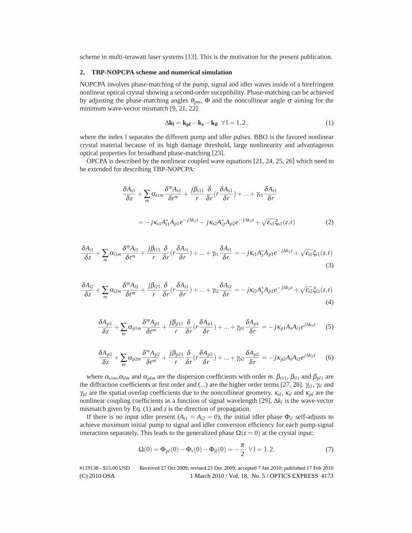
NOPCPA involves phase-matching of the pump, signal and idler waves inside of a birefringentnonlinear optical crystal showing a second-order suceptibility. Phase-matching can be achievedby adjusting the phase-matching angles θpm, Φ and the noncollinear angle σ aiming for theminimum wave-vector mismatch [9, 21, 22]:
Δkl = kpl −ks −kil ∀ l = 1,2 , (1)
where the index l separates the different pump and idler pulses. BBO is the favored nonlinearcrystal material because of its high damage threshold, large nonlinearity and advantageousoptical properties for broadband phase-matching [23].
OPCPA is described by the nonlinear coupled wave equations [21, 24, 25, 26] which need tobe extended for describing TBP-NOPCPA:
δAs1
δ z+∑
mαs1m
δ mAs1
δ tm +jβs11
rδδ r
(rδAs1
δ r)+ ...+ γs1
δAs1
δ r
= − jκs1A∗i1Ap1e− jΔk1z − jκs2A∗
i2Ap2e− jΔk2z +√
εs1ξs1(z, t) (2)
δAi1
δ z+∑
mαi1m
δ mAi1
δ tm +jβi11
rδδ r
(rδAi1
δ r)+ ...+ γi1
δAi1
δ r= − jκi1A∗
s Ap1e− jΔk1z +√
εi1ξi1(z, t)
(3)
δAi2
δ z+∑
mαi2m
δ mAi2
δ tm +jβi21
rδδ r
(rδAi2
δ r)+ ...+ γi2
δAi2
δ r= − jκi2A∗
s Ap2e− jΔk2z +√
εi2ξi2(z, t)
(4)
δAp1
δ z+∑
mαp1m
δ mAp1
δ tm +jβp11
rδδ r
(rδAp1
δ r)+ ...+ γp1
δAp1
δ r= − jκp1AsAi1e jΔk1z (5)
δAp2
δ z+∑
mαp2m
δ mAp2
δ tm +jβp21
rδδ r
(rδAp2
δ r)+ ...+ γp2
δAp2
δ r= − jκp2AsAi2e jΔk2z (6)
where αs1m,αilm and αplm are the dispersion coefficients with order m. βs11, βil1 and βpl1 arethe diffraction coefficients at first order and (...) are the higher order terms [27, 28]. γs1, γil andγpl are the spatial overlap coefficients due to the noncollinear geometry. κsl , κil and κpl are thenonlinear coupling coefficients as a function of signal wavelength [29], Δkl is the wave-vectormismatch given by Eq. (1) and z is the direction of propagation.
If there is no input idler present (Ai1 = Ai2 = 0), the initial idler phase Φil self-adjusts toachieve maximum initial pump to signal and idler conversion efficiency for each pump-signalinteraction separately. This leads to the generalized phase Ω(z = 0) at the crystal input:
Ω(0) = Φpl(0)−Φs(0)−Φil(0) = −π2
∀ l = 1,2. (7)
#119138 - $15.00 USD Received 27 Oct 2009; revised 23 Dec 2009; accepted 7 Jan 2010; published 17 Feb 2010
(C) 2010 OSA 1 March 2010 / Vol. 18, No. 5 / OPTICS EXPRESS 4173
In the prescence of wavevector mismatch Δkl, there is an accumulated phase | ΔklL | withpropagation distance. Consequently, the phases of the waves have to change to maintain theΩ =−π/2 criteria (Eq. (7)). This means, that an additional phase will be imprinted on the signalwave during amplification. The phase terms Φp1,p2,s,i1,i2 for the pump waves, signal wave andidler waves can be obtained by solving the imaginary part of the coupled wave equations (Eq.(2-6)) and using the Manley-Rowe-relation. If the input signal intensity is small compared to theinput pump intensity, i.e. in case of low pump depletion, one can obtain a good approximationfor the signal phase at the output for each isolated pump-signal interaction separately (i.e. onepump beam is blocked at this time) [9]:
Φsl(z = L) = Φs(0)− ΔklL2
+arctan{Δkl × tanh[[g2l − (Δkl/2)2]1/2L]
2[g2l − (Δkl/2)2]1/2
} ∀ l = 1,2, (8)
where gl = 4πde f f√
Ipl(0)/(2ε0nplnsnilcλsλil) is the gain coefficient and
de f f = d31 sinθpm −d22 cosθpm sin3φl ∀ l = 1,2 (9)
is the effective nonlinear coefficient. Since the accumulated signal phase Φsl depends on thepump intensity, a shot-to-shot variation of the carrier-envelope phase (CEP) is possible in theparametric amplifier, if the pump intensity is not constant in time. A maximum phase-slippageof π over the crystal length L is acceptable for a coherent built-up of the amplified signal in thesmall signal gain regime [22, 30]. This defines a criteria for the parametric bandwidth and leadsto:
| ΔklL |≤ π ∀ l = 1,2. (10)
We choose the TBP-NOPCPA geometry shown in Fig.2(a), to ensure optimum type-I phase-matching. In this setup, the critical phase-matching angle θpm can be kept the same for bothpump-signal interactions, whereas the internal noncollinear angle σl is adjusted for both inter-actions individually to achieve the broadest amplified signal spectrum. The two pump beams arelocated in the φ -plane, which is perpendicular to the critical phase-matching plane (θ -plane).The change of de f f due to the deviation of the non-critical phase-matching angle φl for theindividual interactions is negligible but nevertheless was taken into account for the numericalsimulations.
This TBP-NOPCPA setup is essentially different from conventional type-I NOPCPA geome-tries, where the so-called tangential phase-matching or the Poynting vector walk-off compen-sation phase-matching are used. In these cases, the pump and signal beam are located in theθ -plane. In this conventional configuration, it would not be possible to achieve a TBP geom-etry, where the two separate pump beams have the same phase-matching angle θpm and thenoncollinear angles σl can be changed without changing θpm.
We perform symmetrized numerical split-step simulations of NOPCPA [26, 28, 32, 33]with the extension to the TBP scheme and including quantum noise field terms εs1,ilξs1,il(z, t)into the coupled wave equations (Eq. (2-6)) [34]. The complex stochastic variables ξs1,il(z, t)have a Gaussian distribution with a zero mean value 〈ξs,il(z, t)〉 = 0 and the correlation〈ξq(z, t)ξ �
r (z′, t ′)〉 = δq,rδ (z− z′)δ (t − t ′) [35]. εs1,il are the noise intensities of the signal andthe idler waves. The spatial overlap coefficient for the signal γs1 is set to zero as the signal prop-agates normal to the crystal plane. We perform the parametric amplification in the time domainwithin the so-called nonlinear step (Eq. (2-6)) for the amplitudes of the signal wave, the OPFin the signal direction, the idler waves, the OPF in the idler directions and the pump waves.For the pump pulses we employ the measured beam shapes: a 6th-order super-Gasussian beamin space and a Gaussian pulse in time. In case of the seed, we use a Gaussian pulse in timeand space as approximation. As further input parameters, we take measured seed and pump
#119138 - $15.00 USD Received 27 Oct 2009; revised 23 Dec 2009; accepted 7 Jan 2010; published 17 Feb 2010
(C) 2010 OSA 1 March 2010 / Vol. 18, No. 5 / OPTICS EXPRESS 4174
characteristics prior to amplification. We choose an unamplified seed spectrum ranging from650 nm until 1060 nm in the simulation to reveal the maximum parametric gain bandwidth.The temporal delays between seed pulse and each pump pulse are chosen to achieve best matchbetween simulation results and experimental outcome. For the broadest signal spectrum, wechoose σ1 = 2.22◦,σ2 = −2.16◦ and θpm = 23.62◦. The wavevector mismatch Δk is assumedto be zero only for the OPF. This approximation is considered valid, since the transition ratefrom the pump photon to signal and idler photon is highest in the direction of smallest phase-mismatch and consequently only in this case efficient amplification of OPF is possible from thequantum noise level [26, 36].
Dispersion, diffraction and spatial overlap due to the noncollinearity for the TBP-NOPCPAprocess is taken into account in the linear step. For the dispersion we expand the spectral phaseΔϕs1,pl,il(ω) in a Taylor series until 4th order, including group velocity mismatch, and apply itin the frequency domain involving the Fourier transform F :
For the diffraction (diff) and spatial overlap due to the noncollinearity (nc), we include a spatialphase term Δϕspatial
s1,pl,il = Δϕncs1,pl,il +Δϕdi f f
s1,pl,il by applying the linear Fourier step to the transposeddata matrices [26, 27]:
A†s1,pl,il(r,z+Δz, t) = F−1{F [A†
s1,pl,il(z, t)]ejΔϕspatial
s1,pl,il } ∀ l = 1,2. (12)
We perform the numerical model, based on Eq. (2-6) and Eq. (11), (12) with 500 split-stepiteration loops for a 5 mm long type-I BBO crystal.
(a) (b)
(c) (d)
Fig. 1. Wave-vector mismatch ΔklL (blue), OPA-phase Φsl(z = L) (red), sum of both (pur-ple) and ΔklL=±π (green) for the cases of (a) σ = 2.22◦, θpm = 23.62◦, L=5 mm, λp=532nm (b) σ = 2.16◦, θpm = 23.62◦, L=5 mm, λp=532 nm (c) σ = 2.155◦, θpm = 23.55◦, L=3mm, λp=532 nm and (d) σ = 2.04◦, θpm = 23.62◦, L=5 mm, λp=515 nm
To directly show, outside the numerical simulations, which spectral components can be am-plified in TBP-NOPCPA employing 5 mm long BBO type-I phase-matching, we calculate the
#119138 - $15.00 USD Received 27 Oct 2009; revised 23 Dec 2009; accepted 7 Jan 2010; published 17 Feb 2010
(C) 2010 OSA 1 March 2010 / Vol. 18, No. 5 / OPTICS EXPRESS 4175
wave-vector mismatch by using Eq. (1) and the signal phase through Eq. (8) separately for eachpump-signal interaction (i.e. while the other pump beam is blocked). The results are shown inFig. 1(a) and (b). According to Eq. (10), the spectral components between 675 nm and 1050 nmcan be amplified in case of TBP-NOPCPA (Fig. 1(a) and (b)) and between 700 nm and 1050 nmin case of broadband OBP-NOPCPA (Fig. 1(a)). This is in agreement with the measured signalspectra shown in Fig. 4, where the unamplified seed spectrum ranges from 650 nm until 970nm. Moreover, Fig. 1 shows, that the signal phase Φsl accumulated over the crystal length L par-tially compensates for wave-vector mismatch ΔklL and pushes the overall phase-mismatch forthe amplified spectral components below the limit in Eq. (10) for each individual pump-signalinteraction. Maximum amplification is achieved, if the criterion for the general phase (Eq. (7))is fulfilled. If there is no idler present at the beginning of the amplification, the idler phaseself-adjusts to maximize the gain. During amplification however, the wave-vector mismatch(Eq. (1)) forces the phases of the waves to maintain this criterion. Nevertheless,we want toemphasize, that it remains to be theoretically investigated, how the total wave-vector mismatchand the total signal phase evolve, if both pump beams are present in the crystal. Nevertheless,the amplified spectra in Fig. 4 show, that the latter unknown effect does not noticeable changethe phase-matched bandwidth compared to taking the phase-mismatch for each pump-signalinteractions separately and applying the criterion for amplification in Eq. (10) afterwards. Thisapproach is even exact for spectral regions in Fig. 4(b), where amplification is only due to onepump beam; i.e. for ≤∼ 700 nm and for ∼700 nm-800 nm.
In principle, such a broad spectrum from 675 nm to ≥1050 nm can also be amplified with asimilar gain using a 3 mm long BBO crystal in OBP-NOPCPA geometry, pumped with about 3times higher intensity at 532 nm (Fig. 1(c)). Unfortunately, such an approach would lead to in-creased OPF and reduced temporal pulse contrast eventually not suitable for high-field physics[26, 31]. Moreover, such a high pump intensity is above the BBO damage threshold for thispump pulse duration. High contrast amplification of sub-three-cycle, TW light pulses was pre-viously demonstrated using 5 mm long type-I BBO at moderate pump intensities [13]. More-over, investigations on TBP-NOPCPA are also of high interest for multiple-color-pumping.For instance, one can perform pumping it with the second-harmonic of Nd:YAG and with thesecond-harmonic of Yb:YAG (at 515 nm) in the same NOPCPA stage to enhance the signalspectrum. A proposed phase-matching for this case is shown in Fig. 1(a) and (d). For example,the important question has to be answered, if a signal spectrum consisting of disjunct spectralcomponents amplified by different pump beams can actually be compressed. The compressibil-ity of such a spectrum is shown in the present investigations.
3. Experimental setup
The experimental TBP-NOPCPA set up is shown in Fig. 2(b). We use a part of the setup of asub-three-cycle, 16-TW NOPCPA laser system described in Ref. [13], which is used for high-field experiments such as high-order harmonic generation from overdense plasmas and electronacceleration [7, 4]. As seed source for the TBP-NOPCPA we use 2 μJ pulses with a spectrumranging from 650 nm to 970 nm (see Fig. 4(a)) and a FWHM pulse duration of 22 ps at 10 Hzrepetition rate. The seed is negatively chirped by using a reflection grism-pair and an acousto-optic modulator (Dazzler, Fastlite). The group delay between the spectral boundaries of thestretched seed is 42 ps. The pump pulses for the TBP-NOPCPA are generated with a commer-cial Nd:YAG laser amplifier (Ekspla), which provides up to 1 J pulses at 532 nm with a FWHMpulse duration of 78 ps at 10 Hz repetition rate. The seed and pump pulses are synchronized inan all-optical way. The TBP-NOPCPA stage consists of a 5 x 5 x 5 mm3 type-I BBO crystaland is pumped with variable total pump energy up to 12 mJ in two beams. The pump beam isrelay imaged from the pump laser output on the BBO crystal and split into two parts (pump
#119138 - $15.00 USD Received 27 Oct 2009; revised 23 Dec 2009; accepted 7 Jan 2010; published 17 Feb 2010
(C) 2010 OSA 1 March 2010 / Vol. 18, No. 5 / OPTICS EXPRESS 4176
Ti:sapphireOscillator
Ti:sapphire9-pass amplifier
PhotonicCrystalFibre
Nd:YAG
Hollow-core Fiber
Ne 2 bar
Grism Stretcher
AOM(Dazzler)
BBO35 x 5 x 5 mm
5.5 fs2.3 nJ
5.5 fs1.6 nJ
1064 nm ~ 10 pJ
532 nm78 ps
12 mJ
25 fs0.8 mJ
5 fs (TL)0.35 mJ
30 μJ
2 μ J
22 ps
0.46 mJ
Compressor:160 mm SF57,100 mm FS, 4 Chirped Mirrors
0.35mJ 7.1 fs10 Hz
Pump Laser
TBP NOPCPA
Pump 1
Pump 2 Signal
BS DS1
DS2
BBO
s1ext
s2ext
Optical axis
qpms1
ext
s2ext
Optical axis
qpm
φ1
2φ
(a)
(b)
Fig. 2. (a) Optical schematic of the TBP-NOPCPA phase-matching geometry. (b) Layoutof the TBP-NOPCPA experimental set up: BS - beamsplitter, DS - delay stage, AOM -acousto-optic modulator.
1 and pump 2) with a 50%:50% beamsplitter. Each pump beam has its own delay stage toachieve temporal overlap between the pump pulses and the seed pulse. The amplified signalbeam is expanded from about 2 mm to 18 mm and compressed in bulk material consisting of160 mm SF57 (Schott) and 100 mm fused silica. After the bulk compressor, the beam is down-collimated to about 6 mm and led into a vacuum compression chamber for final compressionwith 4 positive-dispersion chirped mirrors. The stretcher and compressor together have a calcu-lated B-integral of 0.08 and the compressor has a throughput of 75% (including several silvermirrors).
The pulse duration is measured with a home-built all-reflective single-shot second-order au-tocorrelator, which is described in section 4.
4. All-reflective single-shot second-order intensity autocorrelator for few-cycle pulsecharacterization
Single-shot autocorrelation set ups have been demonstrated many years ago [37][38], as wellas all-reflective multi-shot autocorrelators being able to measure pulse durations of only a fewfemtoseconds [39]. To our knowledge, up to now no all-reflective single-shot second-orderintensity autocorrelator was realized and used to characterize light pulses with a duration ofonly a few cycles and a spectral bandwidth exceeding 300 nm. The following presented set upwas specially designed to measure the duration and intensity distribution of the pulses generatedin Ref. [13] and in the present experiment.
Figure 3 shows the set up of our home-built all-reflective single-shot second-order intensityautocorrelator. The main feature of this device is its minimized dispersion as well as the tem-poral resolution of about 197 attoseconds, which allows the characterization of few-cycle lightpulses. A broad spectral range, from 675 nm up to 1000 nm, made the realization to a majorchallenge.
The set up consists of two irises at the entrance of the autocorrelator allowing an accuratealignment of the incoming beam. For splitting the beam in two identical replicas, geometricbeamsplitting is used, which is done by a D-shaped mirror. This method is used to minimizedispersion in the optical path of the fundamental pulses. Due to the broad spectrum of few-
#119138 - $15.00 USD Received 27 Oct 2009; revised 23 Dec 2009; accepted 7 Jan 2010; published 17 Feb 2010
(C) 2010 OSA 1 March 2010 / Vol. 18, No. 5 / OPTICS EXPRESS 4177
1 2
3
4
5
6
9 78
10
Fig. 3. Setup of the single-shot all-reflective second-order intensity autocorrelator with atemporal resolution of about 197 as/px and an observation window of 565 fs. 1 & 2: en-trance iris, 3: geometric beamsplitter, 4: delay stage with micrometer screw, 5: cylindricmirror, 6: SHG crystal, 7: color-glass filter, 8: achromatic imaging lens, 9: small apertureiris, 10: CCD detector (Larry 3000 USB)
cycle pulses even thin dispersive elements, like plate beam-splitters, would cause significantdistortion of the original pulse. Pellicle beam-splitters are not chosen because of their sensitivityto vibrations. The upper part of the beam propagates in forward direction into the delay stage,whereas the lower part of the beam is deflected by 90◦. In single-shot devices, the delay stageis only used for finding the zero-delay at the intersection point in the nonlinear optical crystaland for calibration. Unlike in a multi-shot autocorrelator the two pulse replicas are overlappedin the nonlinear optical crystal under a horizontal noncollinear angle of σnc = 2.34◦. A cylindricmirror with a focal length of 300 mm placed in front of the crystal generates line foci in thehorizontal plane with a vertical diameter of about 51 μm. This method drastically reducesthe required pulse energy to 10 μJ. With a phase-matching angle Θpm = 42◦ and a thicknessof the BBO crystal of 5 μm, type-I phase-matching for the whole spectral bandwidth of thefundamental is provided, which allows phase matching starting at 465 nm and exceeding 1100nm. The wavelength which has perfect phase matching was chosen to be 583 nm. The deviationfrom the laser central wavelength, located at 790 nm, allows a better phase matching in the shortwavelength region while maintaining acceptable phase matching at long wavelengths.
For alignment purpose, the fundamental light is blocked behind the BBO crystal with a BG37color glass filter. The second harmonic signal is then imaged by an achromatic lens with a focallength of 40 mm and four-time magnified from the crystal plane to the detector. The detectoris a linear CCD array (Larry 3000 USB, Ames Photonics) with 3000 pixels in a horizontal rowand a width of 7 μm each. In the focal plane of the imaging lens, the two second harmonicsignals, propagating in direction of the fundamental beams, are blocked by a small apertureto prevent deteriorations of the autocorrelation signal. The isolated second harmonic photonsat the bisector of the noncollinear angle σnc, carrying the intensity autocorrelation function intheir transversal spatial intensity profile, are recorded by the detector mentioned above. An ad-ditional BG37 color glass filter reduces fundamental stray light reaching the detector.The temporal resolution and observation window, being the two important properties, are de-fined by the maximum width of the signal, which is limited by the aperture of the BBO crystald = 5 mm, and the noncollinear angle σnc. Using basic geometry, the temporal observationwindow τobs can be expressed by
τobs =n ·d · sin(σnc/2)
c(13)
#119138 - $15.00 USD Received 27 Oct 2009; revised 23 Dec 2009; accepted 7 Jan 2010; published 17 Feb 2010
(C) 2010 OSA 1 March 2010 / Vol. 18, No. 5 / OPTICS EXPRESS 4178
where c denotes the velocity of light in vacuum and n the ordinary refractive index of BBOat 790 nm. For σnc = 2.34◦ used in the setup, the obtained observation window has a size ofτobs=565 fs (Eq. (13)). The CCD array with a width of 21 mm, containing 3000 pixels, recordsa four-times magnified image of the signal with an extension of 20 mm. Hence, the achievedtemporal resolution rAC results in the observation window divided by the number of pixels,covered by the signal, and has a value of rAC = 197 as
px for σnc = 2.34◦.To estimate the absolute error of the pulse duration measured with the autocorrelator, the singleerrors have to be investigated. The pulse duration observed by autocorrelation consists of threevariables
τpulse =τAC · rAC
K(14)
where K denotes the deconvolution factor, τAC the FWHM of the autocorrelation trace in pixelsand rAC the temporal resolution of 197 as
px as mentioned above. The FWHM pulse duration(Eq. (14)) is obtained by dividing the temporal FWHM of the autocorrelation trace (τAC · rAC)by the deconvolution factor K. This value is unique and strongly dependent on the pulseshape and hence strongly influences the measurement error. We calculated the deconvolutionfactor for the Fourier transformed pulses of several different spectra of our TW laser system,ending up with a value of K=1.35±(1 ·10−3). The change in the converted spectrum by thephase-matching curve of the BBO crystal has also been considered in this calculation.Fortunately, in single-shot SHG autocorrelation measurement no geometrical distortions occur,since the generated second harmonic signal propagates along the bisector of angle formed bythe input beams. Consequently there are no geometrical effects, decreasing the accuracy of themeasurement [40].An error originating from the calibration ΔrAC was calculated to be 4 as
px , while an error of τAC
could be reduced by interpolation to ΔτAC = 0.1 px.Gaussian error propagation consequently leads to a total error of 0.12 fs for a fourier limitedpulse. The deviation of the measured pulse from the Fourier limited pulse duration causes somedeviation of the deconvolution factor K. Consequently the measurement error is influenced bythis deviation which is hard to estimate, but as pulse duration gets close to the transform limitthis error is also supposed to become very small.
For measuring the pulses of our present set up, the beam was coupled out of the compressorchamber through a 3 mm thick fused silica window. In addition to the window and some air,further dispersion of about 40 fs2 is caused by reflections from seven protection-coated silvermirrors and the 5 μm thick BBO crystal inside the autocorrelator. Of course this dispersion iscompensated by the AOM when measuring the optimized pulse duration.Altogether the presented all-reflective single-shot second-order intensity autocorrelator wasspecially designed to characterize few-cycle pulses. With a temporal observation window of565 fs and a temporal resolution of about 197 as, it is well suited to measure duration and in-tensity distribution of few-cycle pulses at realtime with a repetition rate of 10 Hz given by thelaser system.
5. Results and discussion
The seed is amplified in the TBP-NOPCPA geometry shown in Fig. 2(a) and a signal energy upto 0.46 mJ is achieved. The broadest measured signal pulse spectrum is shown in Fig. 4(b). Thesignal pulse spectrum ranges from 675 nm to 970 nm leading to a Fourier limit of 6.7 fs. TheTBP setup was modified to operate it also as OBP-NOPCPA with the same total pump energyby replacing the beamsplitter with a mirror. A typical signal spectrum in the OBP-NOPCPAcase is shown in Fig. 4(a). This spectrum ranges from around 700 nm up to 970 nm leadingto a Fourier limit of 8.5 fs. The spectral limits in Fig. 4(b) at low wavelength (675 nm and 700
#119138 - $15.00 USD Received 27 Oct 2009; revised 23 Dec 2009; accepted 7 Jan 2010; published 17 Feb 2010
(C) 2010 OSA 1 March 2010 / Vol. 18, No. 5 / OPTICS EXPRESS 4179
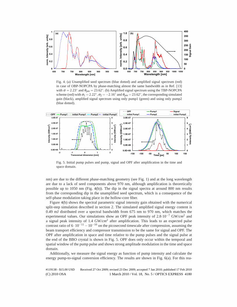
Fig. 4. (a) Unamplified seed spectrum (blue dotted) and amplified signal spectrum (red)in case of OBP-NOPCPA by phase-matching almost the same bandwidth as in Ref. [13]with σ = 2.23◦ and θpm = 23.62◦. (b) Amplified signal spectrum using the TBP-NOPCPAscheme (red) with σ1 = 2.22◦,σ2 =−2.16◦ and θpm = 23.62◦, the corresponding simulatedgain (black), amplified signal spectrum using only pump1 (green) and using only pump2(blue dotted).
0.0E+00
5.0E-08
1.0E-07
1.5E-07
2.0E-07
2.5E-07
3.0E-07
-2 -1 0 1 2Transversal dimension [mm]
Inte
nsity
[GW
/cm
2 ]
0
1
2
3
4
5
6In
tens
ity [G
W/c
m2 ]
OPF Pump1 initial Pump1 Pump2 initial Pump2
0.0E+00
5.0E-08
1.0E-07
1.5E-07
2.0E-07
2.5E-07
3.0E-07
-150 -100 -50 0 50 100 150Time [ps]
Inte
nsity
[GW
/cm
2 ]
0
1
2
3
4
5
6
Inte
nsity
[GW
/cm
2 ]
OPF Pump1 Signalinitial Pump1 Pump2 initial Pump2
Fig. 5. Initial pump pulses and pump, signal and OPF after amplification in the time andspace domain.
nm) are due to the different phase-matching geometry (see Fig. 1) and at the long wavelengthare due to a lack of seed components above 970 nm, although amplification is theoreticallypossible up to 1050 nm (Fig. 4(b)). The dip in the signal spectra at around 800 nm resultsfrom the corresponding dip in the unamplified seed spectrum, which is a consequence of theself-phase modulation taking place in the hollow-core fiber.
Figure 4(b) shows the spectral parametric signal intensity gain obtained with the numericalsplit-step simulation described in section 2. The simulated amplified signal energy content is0.49 mJ distributed over a spectral bandwidth from 675 nm to 970 nm, which matches theexperimental values. Our simulations show an OPF peak intensity of 2.8·10−7 GW/cm2 anda signal peak intensity of 1.4 GW/cm2 after amplification. This leads to an expected pulsecontrast ratio of 6 ·10−11−10−10 on the picosecond timescale after compression, assuming thebeam transport efficiency and compressor transmission to be the same for signal and OPF. TheOPF after amplification in space and time relative to the pump pulses and the signal pulse atthe end of the BBO crystal is shown in Fig. 5. OPF does only occur within the temporal andspatial window of the pump pulse and shows strong amplitude modulation in the time and spacedomain.
Additionally, we measure the signal energy as function of pump intensity and calculate theenergy pump-to-signal conversion efficiency. The results are shown in Fig. 6(a). For this rea-
#119138 - $15.00 USD Received 27 Oct 2009; revised 23 Dec 2009; accepted 7 Jan 2010; published 17 Feb 2010
(C) 2010 OSA 1 March 2010 / Vol. 18, No. 5 / OPTICS EXPRESS 4180
0
0.1
0.2
0.3
0.4
0.5
0.6
0.7
0.8
0.9
1
3 4 5 6 7 8 9 10 11Total Pump Intensity [GW/cm2]
Sign
al E
nerg
y [m
J]
0
1
2
3
4
5
6
7
Con
vers
ion
Effic
ienc
y [%
]
(a)
0.0
0.2
0.4
0.6
0.8
1.0
-100 -80 -60 -40 -20 0 20 40 60 80 100Delay [fs]
norm
. Int
ensi
ty [a
rb. u
nits
]
FWHM = 7.1 fs deconvoluted
(b)
Fig. 6. (a) The dotted curves show the TBP-NOPCPA pump-to-signal conversion efficiencyfor the case of the red signal spectrum shown in 4(b) (green) and for the case of the signalspectrum similar to the red curve shown in 4(a)(black) with σ1 = −σ2 = 2.23◦ and θpm =23.62◦. The solid curves show the corresponding signal energy as function of total pumpintensity. (b) Measured second-order single-shot autocorrelation (solid black curve) andcalculated autocorrelation trace (red dotted curve)
son, we are able to investigate, if the phase-matching (σ1 =−σ2 = 2.23◦ and θpm = 23.62◦) forthe TBP-NOPCPA geometry aiming for a spectrum similar to one also achievable with OBP-NOPCPA (the case of Fig. 4(a)) is comparable to the conversion efficiency of the TBP-NOPCPAphase-matching geometry in case of Fig. 4(b) with broader amplified bandwidth. As result, theconversion efficiency is comparable within the error bars for both cases. Moreover, we measurethe pulse duration of the amplified and compressed broadband signal pulse via an all-reflectivesecond-order single-shot autocorrelation. The results are shown in Fig. 6(b) and reveal a FWHMpulse duration of 7.1 fs, whereas the Fourier-limited FWHM pulse duration is typically 6.7 fs.Consequently, compression is achieved to within 6% of the FWHM Fourier-limit. This im-portant fact reveals the compressibility of the whole amplified signal bandwidth, although thissignal spectrum is composed of two individual NOPCPA interactions taking place in the samenonlinear crystal. A deconvolution factor of 1.4 is calculated from the spectrum. TBP-NOPCPAalso makes an additional spectral shaping possible compared to OBP-NOPCPA; i.e. shaping ofthe steep edge at 700 nm in the amplified signal spectrum in Fig. 4(a). This can potentiallyprevent pulse satellites from occuring after compression if a saturated TBP-NOPCPA stage isused, which would be present due to a sharp spectral edge even in case of compression closeto the Fourier-limit [11, 12, 13]. In this case, a better pulse contrast is achievable due to animprovement of the foot of the compressed pulse, using a saturated amplifier stage.
Furthermore, there have been concerns, that a transient grating generated by the intersectingpump beams could potentially degrade the signal beam quality, since the amplification stronglydepends on the pump intensity. For this reason, we investigate if there is an intensty grating (dueto interference) present inside the BBO crystal and whether this grating negatively affects thesignal beam quality. For this purpose, we image the BBO crystal plane with an achromatic lensonto a CCD camera with a pixel size of 6.7 x 6.7μm2. We magnify the object with a calibratedfactor of 11 and verify, that crystal defects in the crystal are sharp on the CCD image in anycase.
Firstly, we imaged only the intersection of the two pump beams and recorded the magnifiedcrystal plane as a function of relative polarization orientation of the two beams. In this case,the seed was blocked before the crystal. The images and their lineouts are shown in Fig. 7(c)and (a), where 0◦ denotes parallel polarization orientation of the two pump beams and 90◦corresponds to orthogonal relative polarization orientation. We found, that if the polarizationof the two pump beams is parallel to each other and thus allow for interference taking place,
#119138 - $15.00 USD Received 27 Oct 2009; revised 23 Dec 2009; accepted 7 Jan 2010; published 17 Feb 2010
(C) 2010 OSA 1 March 2010 / Vol. 18, No. 5 / OPTICS EXPRESS 4181
Fig. 7. Image of the BBO crystal plane magnified by factor 11 on a CCD camera: (a)Image line outs of the crystal plane. (b) Image of the amplified signal beam profile. (c)Image of the intersecting pump beam profiles in the crystal plane with varying relativepolarization orientation: (0◦ denotes parallel, 90◦ denotes orthogonal polarization of thetwo pump beams).
there is clearly a pump intensity modulation present (see Fig. 7) in the crystal plane with aperiod of ∼ 7μm, taking the magnification factor into account. This modulation vanishes incase of orthogonal polarization between the two pump beams, because then there is no inter-ference possible. Consequently, this optical set up is able to resolve an intensity grating due tointerference inside the BBO crystal.
Secondly, we unblocked the seed and measured the magnified image of the amplified signalin the crystal plane, while the pump beams are blocked after passing through the crystal. Figure7(b) and (a) show, that we observed no signal intensity modulation due to the pump interferencein the beam profile and the corresponding lineout. This can be explained as follows:
The transient grating due to the interference between the two pump beams inside the BBOcrystal evolves on the angle bisector in between the pump beams. Since the two noncollinearangles are not the same, the signal beam traverses this bisector leading to a transversal shiftwith respect to the bisector of half a grating period over the crystal length. Consequently, thissmearing effect can prevent the pump grating from degrading the signal beam quality. Apartfrom general noncollinear smearing, other effects like the Poynting vector walk-off can alsocontribute to this effective smearing.
6. Conclusion
We outlined a new concept (TBP-NOPCPA) for the generation of few-cycle, high-contrast,multi-terawatt light pulses. Moreover, the present experiment demonstrated compressibilityof an amplified signal pulse, whose spectral components result from amplification by twoseparate pump beams in the same nonlinear crystal. In this context, we experimentally showedamplification and compressibility of the signal between 675 nm and 970 nm leading to7.1-fs, 0.35-mJ light pulses after compression to within 6% of the FWHM Fourier-limit.Technical details of few-cycle pulse characterization are outlined. We investigated geometry,phase-mismatch, signal gain bandwidth, pump-to-signal conversion efficiency and signalbeam quality for this new broadband φ -plane-pumped TBP-NOPCPA scheme. Additionally,we performed numerical split-step simulations of TBP-NOPCPA to obtain the parametricgain curve and to study the level of OPF. The temporal pulse contrast ratio was simulatedto be around 10−10 on ps timescales after amplification and compression. It was shown thatthe accumulated OPA phase partially compensates for wave-vector mismatch to maintain
#119138 - $15.00 USD Received 27 Oct 2009; revised 23 Dec 2009; accepted 7 Jan 2010; published 17 Feb 2010
(C) 2010 OSA 1 March 2010 / Vol. 18, No. 5 / OPTICS EXPRESS 4182
maximum gain and leads to extended broadband amplification. Summing up, the presentinvestigations revealed, that TBP-NOPCPA is a promising parametric scheme without adecrease in amplified signal compressibility, amplified signal beam quality and conversionefficiency, compared to conventional one-beam-pumping NOPCPA. The presented theoreticalconsiderations and numerical simulations showed, that amplification is possible between 675nm and 1050 nm in a 5 mm long BBO crystal. Consequently, high-contrast, sub-7-fs, multi-TWpulses are achievable with a 5 mm long type-I BBO crystal, pumped at 532 nm, in case ofTBP-NOPCPA.
Acknowledgements
This work was supported by Deutsche Forschungsgemeinschaft (contract TR18), the as-sociation EURATOM-Max-Planck-Institut fur Plasmaphysik and by the Cluster of ExcellenceMunich center for Advanved Photonics (MAP). D. H., who mainly worked on experimentaland theoretical TBP-NOPCPA, is also grateful to Studienstiftung des deutschen Volkes. R.T., who mainly worked on pulse diagnostics and the seed source, is thankful to DeutscheForschungsgemeinschaft (contract TR18).
#119138 - $15.00 USD Received 27 Oct 2009; revised 23 Dec 2009; accepted 7 Jan 2010; published 17 Feb 2010
(C) 2010 OSA 1 March 2010 / Vol. 18, No. 5 / OPTICS EXPRESS 4183