100 CLEAN TECHNOLOGY, DECEMBER, 1996, 2(2) pp 100-125
Research Investigations at the Municapal (2x35) and Clinical (2x5 MW) Waste Incinerators in Sheffield, UK
Professor J. Swithenbank, Dr V. Nasserzadeh, Dr B.C.R. Ewan, L Delay,
Sheffiled University Waste Incineration Centre(SUWIC)r
Sheffiled University, Sheffield, UK
D. Laurence, B. Jones,
Sheffield Heat & Power Ltd, Sheffield, UK
Attract : After recycle of spent materials has been optimised, there remains a proportion of waste which
must be dealt with in the most environmentally friendly manner available. For materials such as municipal
waste, clinical waste, toxic waste and special wastes such as tyres, incineration is often the most appropriate
technology. The study of incineration must take a process system approach covering the following aspects:
• Collection and blending of waste,
• The two stage combustion process,
• Quenching, scrubbing and polishing of the flue gases,
• Dispersion of the flue gases and disposal of any solid or liquid effluent.
The design of furnaces for the burning of a bed of material is being hampered by lack of an accurate
mathematical model of the process and some semi-empirical correlations have to be used at present. The
prediction of the incinerator gas phase flow is in a more advanced stage of development using computational
fluid dynamics (CFD) analysis, although further validation data is still required. Unfortunately, it is not
possible to scale down many aspects of waste incineration and tests on full scale incinerators are essencial.
Thanks to a close relationship between SUWIC and Sheffield Heat & Power Ltd., an extended research
programme has been carried out ar the Bernard Road Incinerator plant in Sheffield. This plant consists of two
Municipal(35 MW) and two Clinical (5MW) Waste Incinerators which provide district heating for a large part
of city. The heat is distributed as hot water to commercial, domestic ( >5000 dwelling) and industrial
buildings through 30km of 14" pipes plus a smaller pipe distribution system. To improve the economics, a 6 MW generator is now being added to the system.
During the last decade, many investigations have —.. .,, , .system. This has provided a data base against which
been catrried out (Ref. 1 to 16) and a SUWIC ,, , ,models can be tested.laboratory is located at the plant.
Some of our specific research studies are as ….2. Computational Fluid Dynamics (CFD) has been
follows:-used to study the flow through the heat removal and
gas scrubbing systems. The design of such systems has1. Determination of the temperatures and gas .,
evolved rapidly m recent times as incinerators have compositions (experimental measurements) at all acess , , , r .
developed trom simple coverd bonfires to sophisticated points in both the municipal solid waste plant and the
process equipment. An important observation from these clinical waste plant, including the flue gas scrubber . t
studies is that there is often a large "dead water”
CLEAN TECHNOLOGY Vol 2 No 2
Research investigation 101
region in the radiation shaft. Techniques to eliminate
this region by suitable use of baffles and secondary air
jets have been investigated. Implementation of design
changes derived using CFD has successfully reduced
incinerator CO emissions.
3. The fate of contaminants such as heavy metals
merited specific attention. Low volatile matals and
compounds are found to remain in the ash, while some
find their way into scrubber liquor. The latter have
been successfully removed by TMT15. More volatile
material such as mercury may be captured in an
activated charcoal filter.
4. Dioxin emissions are subject to very tight
legi이ation and can pose problems in their removal.
Fortunately, they also can be captured in activated
carbon. Our tests carried out on the Sheffie너 clinical
incinerators before and after cleaning the boiler have
been shown that the unit before cleaning produces
300% more dioxin than after cleaning.
5. Legislatiopn calls for a gas residence time of 2
seconds above a specified temperuture. A technique
has been evolved to actually measure the residence
time in the large MSW and Clinical Incinerator Plants
based on the principle of injecting a pseudo-ramdom
tracer of methane. This produces variations in the
concentration of carbon dioxide in the flue which can
be sensed with a specially developed infra-red detector.
The cross-correlation of the input and output signals
gave the impulse response of the system which
confirmed the by-passing predicted by the CFD
analysis.
6. The mixing of the secondary air has been found
to be weak in both the MSW and the Clinical
incinerators. The application of a mixing theory based
on the turbulence structure and mathematical modelling
incicates how the mixing may be optimised. This
concept can be applied also to the injection of
ammonia/urea for the control of NOX.
7. Corrosion in boilers can be expected to take place
at some time in the boiler's life whether it is fired by
coal, oil or municipal waste. The rates of corro어on
however are very different for these different fuels and
are dramatically influenced further by boiler design,
operating conditions and protective mearures.
Computational Fluid Dynamics has been used to assess
the overall incinerator design features such as
height/width ratio, inlet velocities and inlet geometry on
corrosion rates in boilers. The power of the technique
in enabling the modelling of superheater inlet velocity
contouring by secondary injection, and demonstrating
the areas most at rick by particle impingement is of
enormous value in time and cost saving both at the
design and the commissioning stages of incinerator
plants.
8. The total toxic fly-ash produced in the UK is
approximately 750,000 tonnes/year from municipal
incinerators alone. We have studied a novel technique
to detoxify/recycle the generated toxic fly-ash. Our
approach is based on the fact that sintering or Halting
of this ash results in destruction of its tixic organic
components, and also fixation of its hweavy metal
content to form an unleachable material which can be
used in foundations and building roads. A key aspect
of this work is the technique used to ensure the energy
efficiency of the sintering/melting process. This is based
on the application of a regenerative heating concept.
The conclusions of the research are expected to have
an impact on future codes of practice and standards
dealing with toxic fly-ash. Thus the harzadous material
which is now being landfilling by the waste
incineration industry may be converted to an innocuous
product which can be used safely by the construction
industry.
9. Another research programme which is being
carried out at Sheffield is risk assessment studies of
waste incinerator plants. The overall objective of this
project is to provide a methodology for assessing the
risks to human health(the work-force inside the
incinerator plant) posed by municipal/clinical waste
청정기술 제2권 제2호
102 J. Swithenbank
incinerators, which can be used directlyn by the
incineration industry in the UK, Europe and the USA.
Use of the methodology will improve the basis for
decision making in assessments of the comparative
benefits of alternative waste management stratigies.
Thus practical experience shows that incineration is a
maturing technology which is rapidly developing to
fulfil an urgent requirement in society for the removal
of polluting materials.
Sheffied MSW Incinerator (35 MW) Plant
The Sheffield incinerator plant became fully
operational in 1978. It is a twin stream unit designed
to bum up to 20 tonnes/hr of raw municipal waste
(lOtormes/hr per grate). The facility takes approximately
80% of Sheffield city's domestic waste and a limited
quantity of commercial and trade waste which provide
a totoal weekly input of some 2500 tonnes. The
incinerator is fitted with steam raising boilers of
conventional water tube design and the steam generated
is used to heat 5,000 houses and many commercial
premises in the area.
Figure 1 shows a schematic layout for one of the
streams. The refuse is tipped by the collection vehicle
into the reception pit and using a tulip grab crane the
refuse is transferred onto a chain conveyer. From this
conveyor the refuse drops down the feed chute at the
bottom of which a ram feeder pushes the waste onto
the gate. The ram feeder speed determines the feed-rate
and tne sensors fitted in the chute monitor the refuse
level and control the feed conveyor. The grate is
inclined and made up of 6 independently driven
variable speed rollers, each roll is reversible and has its
own primery combustion air supply. Secondary
combustion air is also be supplied over the grate. The
refuse moves slowly down the grate and is normally
burnt out before reaching the final roller. The grate ash
drops into a water quench bath, which provides an air
seal for the combustion chamber, before discharging
onto a transfer conveyor to the ash skip. The
combustion gases pass over the boiler and steam drum
before passing through the electrostatic precipitator. The
fly-ash is collected in skips, the cleaned gas is
discharged to atmosphere via the chimney. When steam
demand from the housing complex is low, heat can be
dissipated using air cooled condensers.
CLEAN TECHNOLOGY V이 2 No 2
Research investigation 103
Sheffield Clinical Incinerator (5 MW) Plant
The Sheffield clinical waste incinerator became fully
operational in March 1991. The throughput of this
twion stream system is up to 2 tonnes per hour, 8
hours per day. Operation is no more than 6 days per
week. The daily throughput is limited by the computer
controls on the incinerator units. The estimated annual
throughput is 3300 tonnes. The equipment (Figure 2)
comprises two identical streams each of which consists
of a hydraulic power loader and tipper,
sub-stoichiometric first stage, gas co-fired secondary
stage, steam raising boiler, exhaust gas. Waste is fed to
the incinerator units by an automatic system which
weighs individual skips and empties them into a
hydraulic ram which loads the incinerator. This system
is linked to the computer controls and automatically
limits the daily bum to 6 tonnes per stream. After the
waste has been fully combusted, the ash is manually
removed on a daily basis into specially designed skips
to minimise the losses. Both incinerator units operate
on a two sta 응 e combustion principle, each unit
comprises two interconnected combustion chambers,
mounted one above the other. Waste is loaded into the
primery chamber into which a small flow of air is fed,
and tne material is initially ignited by auxiliary burners.
The supply of air to the primery chamber is limited
such that the waste decomposes under quiescent
conditions so minimising the carry over of particulate
material, which could subsequently contribute to stack
emissions. The partial combustion products pass
upwards to the after-burner chamber tertiary air is
added and the gas temperature is elevated if necessary
by the addition of heat from a natural gas burner. The
flue gases then pass from the upper chamber and are
normally drawn, via the induced draft fan, through the
fire tubes of a single pass waste heat boiler. The
untreated flue gas from the incinerator passes through
the tube side of a gas to air heat exchanger and into
the gas scrubber. The scrubber is fitted with high and
low level switches, and an over temperature switch. In
the event of over temperature, the emergency water
spray will commence. A pH meter controls kthe
addition of caustic soda solution to the scrubber liquor
to maintain a reasonably constant pH of around 8. The
caustic liquor filtration system comprises a plate
pressure filter, 2 filter pumps, a filterate storage tank
and discharge pumps. The cleaned saturated gas
discharged from the scrubber is then ducted directly
into the inlet of the main fan. A forced draught fan
passes clean ambient air through a steam heater. The
heated air is ducted through the shell side of the gas
to air heat exchanger.
Fig. 2
청정기술 제2권 제2호
104 J. Swithenbank
This heated air is then discharged into the common
flue downstream of the main fan. A bleed of part of
the heated air is put directly into the scrubber outlet
duct to ensure that the cleaned gas temperature to the
main fan exceeds the dew point. ConEd of the heat
output from the steam heater is determined by a preset
temperature sensor positioned in the common duct
downstream of the two main fans. The steam heated
air system on both streams are run simultaneou이y 24
hours per day, 7 days per week. The heated air
maintains a sufficiently high temperature of the flue
gas duct work down line of the gas scrubbers to
prevent condensation within the ducting as well as the
formation of a steam plume at the outlet of the stack
during plant start up. In the event of only one stream
being operational the running of both heated air
systems ensures that untreated flue gases do not enter
the non-operational system at the confluence fo ducting
at the connection into the common flue to the stack.
The steam air heater consumes approximately 15 to 17
tonnes of steam per day, corresponding to about 30%
of the total steam generation of the incinerator. The
flue gas is discharged to atmosphere via the 75 metre
stack attached to the adjacent municipal incinerator.
Experimental Programme
The experimental program at the Sheffield municipal
and clinical waste incinerator plants consisted of the
following stages
1. Analysis of the waste feed and incinerator
residues;
2. Determination of the temperature profile/
combustion air distributions within the incinerators;
3. Gaseous emission testing; dioxin/furan, total
particulates, HC1/HF, CO, CO?, O2, VOC, NOX and
SO: emissions, heavy metals measurements, gas flow
rates and moisture content.
Several other miscellaneous measurements are also
made to monitor the effect of variation of operating
parameters on the performance characteristics of the
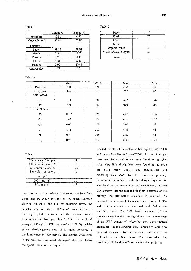
incinerators. Typical analysis of Sheffield municipal and
clinical wastes are given in Table 1 and 2. Typical
gaseous emission levels at the electro-static precipitator
outlet for the MSW incinerator are shown in Table 3.
A summary of the results obtained from one of our
emission trials at the Sheffield clinical waste incinerator
plant is given in Table 4. The unbumed carbon content
of the grate ash varied between 2.1 to 8.7%. An
additional test was also carried out to determine the
unbumed carbon content of fly ash(particulates) which
were deposited on the surface of the boiler tubes. The
test showed a relatively low value of 1.2% unbumed
carbon for phasee particles. The measured O? content
of flue gas after the boiler (before the scrubber) varied
between 8.9 to 12.5%. The CO concentrations at the
boiler exit (before the scrubber)were between 230ppm
and 657ppm. The measured moisture content of gas at
the boiler exit was about 12 to 13%. The mean
emitted carbon monoxide (CO) concentration at the
base of the chimney (after the scrubber) was 157
mg/m3 (STP, dry, cirrected to 11% O2 ). The lower
levels of CO and CO? at the base of the chimney
(after the scrubber) inducated that some of the CO and
CO2 react with the caustic solution in the scrubber to
yield corbon salts (e.g. NaCO3). The addition of heated
air to the main flue duct also results in dilution, hence
lower unaccounted concentration of CO and CO? at the
base of the stack. The measured O2 level at the base
of the chimney was up to 17.1%. Heavy metals
concentrations were measured using Inductively Coupled
Plasma Spectrometry (ICP). Measured heavy metal
concentrations in the flue gas, ash, scrubber liquor and
filter cake are given in Table 5. Much of the mercury
and cadmium released in the incineration process was
found in the scrubber liquor and filter cake. Additional
tests were also carried out in shich the scrubber liquor
was treated with Degussa TMT 15 solution before
discharging to the sewer. The aim was to investigate
the efficiency of this solution in lowering the heavy
CLEAN TECHNOLOGY Vol 2 No 2
Research investigation 105
Table 1
weight % volume %Screening 12.31 4.30
Vegetable and
putrescible
35.46 25.85
Paper 31.12 38.91Metals 5.34 8.65Textiles 1.70 3.41
Glass 9.31 6.44Plastics 2.97 10.43
Unclassified 1.79 2.01
Table 2
Paper 20Plastic 25Glass 10Metal 10
Organic waste 5Miscellaneous hospital
waste
30
Table 3
Mean CoV % Max MinParticles 500 124 2795 16CO (ppm) 176 113 787 5.5
Acid Gases:
SO2 338 38 672 176
HC1 689 26 949 345Heavy Metals :
Pb 10.37 125 49.6 0.09
Cu 1.47 85 4.18 0.13
Cd 0.60 128 3.47 nd
Cr 1.11 117 4.85 nd
Ni 0.70 108 2.87 nd
Hg 0.26 23 0.39 0.21
Table 4
CO concentation, ppm 57 ICO? concentration, % 3.1O2 concentration, % 16.9Particulate emission,
-3mg m
311
NOX, mg m'3 51 1SO?, mg m 3 17
metal content of the effluent. The results dbtained from
these tests are shown in Table 6. The mean hydrogen
chloride content of the flue gas measured before the
scrubber was well above 1000mg/m3 which is due to
the high plastic content of the clinical waste.
Concentration of hydrogen chloride (after the scrubber)
averaged 150mg/m3 (STP, corrected to 11% O2), whilst
sulphur dioxide gave a mean of 11 mg/m3 compared to
the limit value of 300 mg/m3. The average NOx level
in the flue gas was about 36 mg/m3 also well below
the specific limit of 350 m이m七
Emitted levels of tetrachloro-dibenzo-p-dioxins(TCDD)
and tetrachlorodibenzo-furans(TCDF) in the flue gas
were well below and furaiis were found in the filter
cake. Very little dioxin/furan were found in the grate
ash (well below Ing/g). The experimental and
modelling data show that the incinerator generally
performs in accordance with the design requirements.
The level of the major flue gas constituents, O2 and
CO2 confirm that the required rich/lean operation of the
primery and sfter-bumer chambers is achieved. As
expected for a clinical incinerator, the levels of SOa
and NOx emissions are low and well below the
specified limits. The HC1 levels upstream of the
scrubber were found to be high due to the combustion
of the PVC content of refuse but they were reduced
dramatically at the scrubber exit. Particulates were also
removed efficiently by the scrubber and were then
collected in the filter press. The observation that
practically all the dioxin/furans were collected in the
청정기술 제2권 제2호
106 J. Swithenbank
Table 5
Element Ash //g g'1 Scrubber liquor
(before treatment),
mg/litre
Filter cake
昭g'*
Flue gas
(particulates),
mg m'3
Flue gas(vapour
phase), mg m
Hg <2 2.09 3294 0.03 0.17
Cd 9 <0.02 1649 0.06 0.50
Pb 679 506 11831 2.12 4.7
Cu 3740 0.06 920 0.22 1.1
Ni 159 <0.02 69 0.02 0.02
Cr 1420 <0.02 1154 0.02 0.02
Zn 3790 6.1 34890 0.01 1.5
Table 6
Element Untreated liquor mg/litre Treated liquor with TMT 15,
mg/litreHg 6.03 0.08
Cd 37.5 0.29
Pb 37.4 0.24
Cu 3.73 0.03
Ni 0.27 0.12
Cr <0.02 <0.02
Zn 242 61
filter cake is consistent with other investigations of
incinerator emissions. Whenever particulates are formed
in the combustion, either as fly-ash from the
silica/metal content of the waste feed, or as
carbonaceous material formed in the situation of
imcomplete combustion, the major part detected dioxins
and furans are adsorbed onto the surface of the
particulates. Dioxins and f니rans rarely exist in the
vapour phase under such conditions. The very low level
of dioxion/furan found in the scrubber liquor is also
entirely consistent with literature observations. Dioxin
and furans are almost insoluble in water. Where
particulates and water from an incineration process
condense together, dioxins and furans are always
adsorbed onto the solid particles. Our tests showed that
low volatile heavy metals were mostly retained in the
grate ash whilst most high volatile met시s were found
in the filter cake and the scribber liquor. Wet
scrubbing processes have proved to be successful in
removing heavy metals from the flue gasas, in which
case the metals usually end up in the waste water. The
results obtained from our tests at the Sheffield clinical
incinerator showed that an optimal application of
Degussa TMT 15 to the waste water could lead to
acceptable residual concentrations of heavy metal ions
which are well below the specified limits. Depending
upon the type of heavy metal and composition of
waste water, residuals between 0.01 and 1 mg heavy
metal ion per litre waste water were obtained.
Use of Computational Fluid Dynamics (CFD) to
simulate 사诚 Effects of Design and Operating
Parameters on the Overall Performance of the
Sheffield MSW & Clinical Incinerator Plants:
The need for a better understanding of incinerator
flows is growing due to the increasing use of
incineration as a solid waste management tool, shifts in
the economics of incineration, and public concern over
emissions. The directly fired water-walled,
municipal-waste mass-bum incinerator is the dominant
design and its over-fire water wall region is the cnici시
CLEAN TECHNOLOGY V이 2 No 2
Research investigation 107
link between the grate section designed to bum
heterogeneous waste stream and the heat transfer and
gas cleaning sections with their own input requirements
for optimal performance.
Incineration is one of the most complex unit
operations presently in use. The processes occurring
within a burning refuse bed in이pyrolysis, solid
and gas combustion, conductive, convective and
radiative heat transfer, mass transfer, and gas flow
through randomly packed beds of material whose size,
shape and orientation is continuously changing. In view
of the complexity of these processes, it is not
surprising that the design of incinerators has developed
more as art than a science.
The many design variables open to the designer (e.g.
type of grate, number of grate sections, amount of
exess air, primery and secondary air distribution, refuse
bed height, grate speed and the radistive transfer to the
top of the refuse bed) strongly suggests that present
designs and mode of operationn are far from optimum.
This is partially confirmed by the w너e variations
reported for maxumum burning rates, and for exess air,
air distribution, and grate and furnace configuration in
different units, as well as by the w너e variation in
residue quality observed in practice. It should be
possible to reduce the capital costs of incinerators as a
better understanding of the effect of different variables
is obtained, particularly those pertaining to air flow rate
and distribution because of their profound influence on
burning rates, rates of particulate emission and on the
size of the required gas cleaning equipment. From the
operational standpoint the major difficulties appear to
be dynamically adjusting operating conditions to
compensate for the rapid changes in refuse quality and
quantity, and the lack of techniques available for
rapidly evaluating residue quality (i.e. unbumed carbon
in ash). The operator has less flexibility than the
designer in dealing with the variations in refuse quality
and quantity and must cope with wide variations in
refuse composition and moisture content by adjusting
the grate speed and air flow rate and to a lesser extent
air distribution.
One of the major reasons for studying the existing
incinerator design is to enhance the mixing processes
inside the furnace. The existing designs have been
shown to have very poor mixing characteristics. In the
case of a constant quality fuel combistion system, the
undergrate and the secondary air ratios could be
established and would depend largely on the stoker
characteristics and furnace configuration. Such a system
can be operated at practically constant temperatures
with minor manual ratio adjustments when required. In
the case of a refuse combustion system, however, such
operation becomes very difficult, if not impossible. The
variable quality of the refuse, changing not only from
one hour to another, but actually from minute to
minute, ideally requires continuous adjustments in the
undergrate/secondary air ratios to offset the varying
combustion rate characteristics and the resulting heat
release per unit time of various refuse constituents.
The following section presents the findings from our
CFD modelling studies of Sheffield MSW and Clinical
incinerators.
a) Effects of Installing different Baffle Confirmation
on the Overall Performance of the Sheffield MSW
Incinerator:
As shown in Figure 3, our computational fluid
dynamics(CFD) model of the Sheffield MSW
incinerator plant cinfiimed the existence of a large
re-circulation zone inside the vertical shaft. The
temperatures at the boiler exit were about 1000K and
the key residence times in the furnace and shaft ranged
between 0.5-1.5 seconds. Using the mathematical
modelling technique to remove this re-circulation zone,
a baffle was introduced into the mainstream inside the
shaft. Conventional design technoligy for passive
(baffle) systems is an empirical art, often based on
isothermal physical modelling using water or air
models. However, modem computation technology
청정기술 제2권 제2호
108 J. Swithenbank
permits the effect of geometrical design and process
operational changes to be investigated economically and
quickly using more realistic non-isothermal flow fi이ds.
Fig. 3
The comparison between the predicted performance
of the existing incinerator design and the suggested
modified design showed that the introduction of a
water cooled baffle into the gas mainstream inside the
vertical shaft and increasing the use of the secondary
air by 57% could give rise to a significant change in
flow field inside the Sheffield incinerator. This will
reduce the temperature and improve the temperature
profile at the boiler exit, increase the gas residence
times and reduce the pollutant emissions from the
stack. In addition, the boiler efficiency increases by
nearli 8% and it is estimated that there will be an
18% reduction in running and maintenance costs as a
result of the new modified design.
Four different baffle configurations based on the
concept of eliminating the re・circ니ation zone in the
shaft were studies and the resulting flow fields obtained
from these cases are shown in Figure 4 to 7. The
computer code (FLUENT) was used to perform the
calculations. For each case, a detailed description of the
flow field was calculated and key information was
calculated such as; velocity vector plots, temperature
profiles, CO levels and estimates of the re-circulation
zone inside the shaft compared to the other three cases.
Althrough temperature profiles for all four cases
inside the furnace are similar, the temperatures at the
boiler exit for case one, have the lowest value
compared to the other cases. Cases 2, 3 and 4 show
little improvement in terms of lower exit temperatures
over the original design. Appreciable cold and hot spots
are seen in the shaft for these cases which make their
design unattractive compared to the evenly distributed
temperature profile in the shaft for the case one. The
predicted carbon monoxide levels at the exit for all
four cases are relatively low compared to the original
design.
4
Fig. 5
(KtEKT ■ 1 n 1 tf-iir*aXITT VKICRS 区応S/SEC I 2*트 . « 卜나无 nt応、
XY (V Dj)LMAX- ■ &4E*0Q 1 J-0 COWIN
CLEAN TECHNOLOGY Vol 2 No 2
Research investigation 109
Fig. 86
oeifHf • 1*aocilr v?cr«s OtlSEVSfC---------- i-------- A.**€ • <
1-0 OOutooy X g)
Fig- 9
Fig. 7
Residence times in all other three cases are relatively
long.
b) Effect of Large High Speed Jets on the overall
Performance of the Sheffield MSW and Clinical
Incinerators.
The clinical role played by the large high speed
secondary air jets acheiving a desirable state of mixing
and optimising the overall performance of the
incinerator plants were investigated using CFD models.
The effect of high speed secondary air jets on both theFig. 10
청정기술 제2권 제2호
110 J. Swithenbank
Fig. H
Fig. 12
overall performance of the Sheffield MSW
incinerator and the gas residence times was investigated
using CFD models. Here, in the proposed design,
instead of having a very large number of secondary air
injecttion pots(44 jets in total) in the same horizental
plane, eight large secondary injection ports are situated
on a plane at an angle of 45° to the vertical (Figure
8). Each jet is positioned on the side wall at 75 cm
separation and is fired into the main flow tangentially
to a rotational circle at 30° angle to the horizental. The
main feature of this design is the formation of a very
strong re-circulation zone due to the high speed
secondary air injections. Unlike the existing incinerator
drsign in which a re-circulation zone occurs in the
shaft, when the eight high speed injections are
itroduced, the flow field is changed dramatically. The
re-circulation zone inside the shaft which was present
in the existing incinerator design, has disappeared and
the main flow out of the furnace is directed towads the
middle of the shaft. As expected from the structure of
the flow field in this design, the entire volume of the
radiation shaft is used as true combustion space with
no dead spaces and hence marked improvements in
heat exchange are acheived with this system compared
to the original incinerator design. The results show
marked improvements in mixing characteristics and
mean gas residence times in this design compared to
the values obtained for the existing incinerator design.
FLUENT was also employed to predict the three
dimentional reacting flows(gaseous phase) within thw
Sheffield clinical incinerator geometry (Figure 9, 10, 11).
The main objective of this modelling work was to
investigate the influence of the design and operating
parameters on the overall performance of the
incinerator. The modelling work showed that the use of
six large high speed secondary air jet firing toward a
common certre in the inter-connecting duct and
employment of 12 high speed air jets inside the after
burner, produce longer residence times and improve the
temperature profile at the exit. The novel feature of
the proposed secondary air injection system is the
formation of a large size and significantly strong
re-circulation zone located in the interconnecting duct.
The presence of this strong re-circulation zone improves
the overall performance of the incinerator due to
intensive mixing of hot gaseous products(CO, volatile
matter and hydrocarbons) evolving from the refuse bed
with the combustion air supplied as the secondary air,
and thereby greatly improves the gas phase combustion
and helps to reduce emissions of toxic gases. As
shown in Figure 12, the main feature of this design is
the formation of a very strong re-circulation zone in
the downstream area of the incoming flow from the
primery chamber due to the high speed secondary air
injections. Unlike the existing inter-connecting duct
design in which the main incoming flow from the
CLEAN TECHNOLOGY Vol 2 No 2
Research investigation 111
> • /
•'艾/w孕务 K峻纭多多泛务
匕久么,"多匕
",%务物;'A■,財/'
design is the formation of a strong re-circulation zone
upstream of the air ports and near to the gas burner
injection point. In this design, the entire volume of the
chamber is used as true combustion space with no
dead spaces and significant improvements in mixing
characterictics and combustion efficiency are acheived
compared to the existing Sheffield clinical incinerator.
Other studies have shown the benefit of baffles in the
afterburner chamber to improve mixing and res서ence
time.
Fig. 13
Fig. 14Fig. 15
lower chamber passes through the duct with relatively
high velocities and no use is made of secondary air
jets to enhance the turbulent mixing in the duct(Figure
13), when the six high speed injections are introduced,
the flow field inside the duct has changed dramatically.
Due to the injection of high speed secondary air jets, a
rotary motion of gases is induced below the injection
points, which contributes greatly to the mixing process
inside the duct.
The proposed design for the after-burner uses 12
equally spaced, high speed air jets, which are fired
radially into the main flow towards a common certre
(Figure 14). As shown, the main characteristic of this
Mixing
Modelling studies of particle trajectories using
computational fluid dynamics shows the utility if
어mulation for the determination of residence time
distribution in incinerators. These studies indicate that
residence time distributions contain valuable information
that is important to the understanding and evaluation of
mixing processes in the incinerator ober-fire region.
Recent legislation specifies the residence time above a
defined temperature in new incinerators, and these rules
are to be applied to all large incinerators in the near
future. CFD can be used to obtain the residence times
청정기술 제2권 제2호
112 J. Swithenbank
by solving the trajectory equations for infinitesim이
particles. At Sheffield University Waste Incineration
Centre, we have carried out such calculations using the
two-phase capability of the FLUENT code for a
number of commercial and clinical waste incinerators
and we have found that they typically exhibit
unacceptably short residence times due to the fact that
there are dead space regions in the radiation
shaft(Figure 3)
The solution to this problem has also been derived
using CFD models. The technique which we have used
is based on our mixing concepts. These show that the
maximum mixing that can be acheived is related
directly to the mixing power, however, since power can
be expended mixing like with like, the actual mixing
acheived also depends on ensuring that alternate
micro-scale (Kolmogorov) layer must consist of the two
materials being mixed respectively. This criterion can
be satisfied by ensuring that the macro-scale eddies
contain alternate material since it is these eddies which
become the micro-scale eddies by the turbulent
stretching process. Thus if we require to mix uniformly
air jets as are commonly fitted to incinerators, but it
can be acheived by a small number of large secondary
air jets.
Investigations into the Effect of Boiler Deposits on
the Post-Combustion Formation of Dioxins/Furans in
Incinerator Plants:
Recent research work has demonstrated that the
dominant mechanism of Dioxin/Furans formation
involves heterogeneous, surface catalysed between
chlorinated precursors and/or the product of de novo
synthesis, on fly-ash particles held in the relatively
cool(200°C-400°C) post-combustion environment of the
boiler or particulate arrestment equipment. The key
requirements for PCDDs/PCDFs formation are an
oxygen-rich environment, a source of chlorine, and the
presence in the fly-ash of a metal capable of catalysing
a Deacon reaction(e.g.copper). De novo systhesis is
initiated by the formation of chlorine via the action of
oxygen on hydrogen chloride:
MC12 + 考"OlMO + Cl2
MO + 2HC1-*MC12 + H2O
leading to :
2HC1 + y O2^H2O + Cl2 El
Hydrogen chloride is formed as a decomposition
product of the chlorinated organocs such as PVC in the
incinerator, along with fly-ash. Inorganic chlorides (for
example sodium chloride or ferric chloride) are equally
effective sources of chlorine. M(the metal catalyst in
the fly-ash) is typically copper (the most effective
catalyst material), though patassium, sodium, and zinc
have also been positively correlated with PCDDs/PCDFs
formation. Homogeneous gas phase reactions in the
combustion zone generate a range of PICs, both
chlorinated and non-chlorinated precursors on the
fly-ash. These percursors react to form PCDDs and
PCDFs. Taking dichlorobenzene and o-chlorophenol as
typical precursors, the formation of monochloro-CDD
can proceed innitially by oxygen attack on
dichlorobenzene to form a phenoxy radical, which
reacts with chlorophenol to form an intermeadiate
diphenyl ether. Combination of the hydrogen form the
hydroxy radical with chlorine on the adjacent phenyl
ring allows the reamining oxygen to bridge between the
two phenyl rings and complete the dioxin molecule.
The catalytic formation of PCDDs and PCDFs has
been studied by a number of researcher. Two
competing temperature dependent reactions operate;
(a) formation of dioxin (reaching a maximum rate in
the region of 300°C), and
(b) dechlorination/decomposition of dioxin, a reaction
whose rate increases exponentially with temperatire
Above about 200°C the rate of formation exceeds
the rate of destruction, peaking at about 300°C. Above
CLEAN TECHNOLOGY V시 2 No 2
Research investigation 113
Table 7
Sampling Period Substances Reported Measured Concentration
3 hoursDioxhi/Furan in the flue gas
(Before Cleaning Boiler)11.98 ng/nm3
3 hoursDioxi피furan in the flue gas
(After Cleaning Boiler)4.16 ng/nm3
400°C the rate of destruction dominates, and dioxin
levels decrease rapidly. A global heterogeneous
mechanism has been proposed which has been shown
to be in good sgreement with experimental data, this
model is in four stages:
Stage 1: Dioxin Formation Pg + Ps Ds
Stage 2: Dioxin Desorption Ds^Dg
Stage 3: Dechlorination DlProducts
Stage 4: Decomposition Ds^Products
Pg and Ps are precursor concentration in the gas
phase and on the surface of the fly-ash, and Ds and
Dg are concentrations of dioxin on the fly-ash and in
the gas phase. A proportion of PCDDs/PCDFs that are
formed desorb off the fly-ash and exit the incinerator
as a component of the gas phase. However, apart from
the mono-, di-, and tri-chloro species, the major
proportion of PCDDs/PCDFs remain adsorbed onto the
fly-ash, and either exit the stack as a component of the
particulate fraction or are arrested in air pollution
control equipment such as fabric filters.
In order to investigate the effect of boiler deposits
on the post-combustion formation of dioxin/furan in a
large incinerator plant, a series of tests were carried
out at Sheffield clinical incinerator. The main objective
was to show that more dioxins/furans are formed in a
dirty boiler than a cleaned boiler due to the greater
region of suitable environment for their formation. Test
were carried out before and after cleaning the boiler (2
weeks interval). Samples for Dioxin/Furan testing were
collected using an Anderson Universal Stack Sampling
System complying with the U.S Environmental
Protection Agencies Modified Method 5 protocol. The
samples were then analysed by high resolution gas
chromatography and mass spectrometry. Samples were
taken simultaneously at the inlet and outlet of the
boiler. The results obtained from this work are shown
in Table 7. Our results demonstrated 300% more
dioxins/furans production from the boiler before
cleaning compared with after cleaning.
Measurement of Gas Residence Times in Large
MSW Incinerator Plants Using the Pseudo-random
Binary Sequence(PRBS) Tracer Technique:
There is increasing public awareness and concern
over emission from municipal solid waste incinerators.
The value of knowing the gas residence times in large
municipal incinerators and the serious error imposed by
the traditional use of gas volume flow rate based
average residence time with regard to these incinerators
are well recognised.
Article 4 of the EC Directives on both new and
existing MSW incinerators specified that the gases
resulting from the combustion of waste must be raised,
after the last injection of combustion airm in a
controlled and homogeneous fashion and even under the
most unfavouravle conditions, to a temperature of at
least 85O°C, for at least two seconds, in the presence
of at least 6% oxygen. It is subsequently stated(Article
6) that the residence time of the combustion gases at
850°C as specified in Article 4 must be the subject of
appropriate verification at least once before a new plant
begins operating, or in the case of an existing plant,
before 1st December 1996.
청정기술 제2권 제2호
114 J. Swithenbank
Residence time is normally measured by injecting a
tracer such as helium, mercury vapour, sulphur
components or radioactive material at a prescribed
point, which for incinerators is usually specified as the
secondary air entry. The time required for the tracer to
pass through the system is determined by analysing the
concentration of the tracer at the exit as a function of
time. In many systems, this is unsatisfactory due to the
larger number of secondary air inlets. More particulary,
due to the scale of these plants, inconveniently large
pulses of tracer are required to provide sufficient signal
at the outlet plane.
Traditionally, time domain experimental methods
have been used (e.g. step response and pulse response
measurement). However, these measurements suffer
from the drawback that, in the presence of noise, either
the perturbation signal must be so large that the normal
operation of the process is affected, or the
experimentation time must be so long that difficulty
arises in holding the process steady over a sufficiently
long period of time. Any method which can give a
good measurement of the dynamics in a affecting the
normal operation of the process would be most
attractive, and for this reason, we have used a
correlation method.
Examples of the forcing functions are; pulses, steps,
sinusoids, randoTn(noisse) and pseudo-random binary
sequence(PRBS). Akhr이igh in principle the same
information can be gained irrespective of the form of
the input signal, the PRBS is a much more useful and
powerful signal, and it is well established and w거ely
used in the field of process control. On the other hand,
step and pulse factions are dominant forms of input
signals which have been used for years in cimbustion
and reator designstudies, with little or no practical use
of the PRBS. The advantages of the present approach
are as follows:-
1. The PRBS is on the average a steady state
function and the combustor can therefore be operated at
practically steady state
2. The amplitude of the pulse or step signal would
have to be relatively large compared to the PRBS
disturbance and this can result in the system
overloading and un-quantified non-linearities.
3. For a given signal/noise ratio the experimental
time is relatively modest.
4. Many disturbance frequencies are generated for
one easily generated code.
5. Quantitative estimates can be made of the
turbulent mixing noise contribution to the response.
The main objective of our research programme was
to study and develop a cheap, simple and reliable
technical procedure for measuring gas residence times
in the large incinerator plants. This has immediate
importance to existing UK incinerator plants and as an
available technology which has wider implications for
Europe and the USA as well as the increasingly
environmentally conscious Eastern block.
Our research progeamme consistes of four major
parts;
Phase 1: Water model tests,
Phase 2: Gas injection tests in a small-scale
incinerator unit,
Phase 3: Computational fluid dynamic analysis of
residence times,
Phase 4: Residence time measurements on the full
scale 35 MW incinerator using the PRBS tracer
technique.
PRBS Tests at the Sheffield Plant:
The gaseous fuel uesd in the PRBS tests at the
plant was methane (a portable cylinder). The methane
gas flow rate was measured using a rotameter fitted in
the gas line before it was fed into the furnace
(approximately 700 litre/min of methane gas during
CLEAN TECHNOLOGY Vol 2 No 2
Research investigation 115
each injection yielding a mean flow of 350 litre/min).
The PRBS signal (methane gas) was introduced into
the furnace on top of grate roller number 2, through a
2.5 inch diameter nozzle (water cooled probe) via a
side port(Figure 9). The gas solenoid valve was fitted
in the supply line to this port. Here a pseudo-random
signal was used to perturd the process and the output
response (CO? concentration) was detected by a simple
IR absorption fast CO? analyser inserted into the duct
at the boiler exit. This signal was then cross correlated
with the perturbation signal to give a result which can
be shown mathematacally to be identical with the
impulse response of the process. As a preliminary
check to make sure that the system was running
satisfactorily, a blank test was carried out with no gas
injected into the furnace. A series of tests were carried
out using 15, 31, 63, and 127 bit sequence with bit
interval of 1 sec, 333 ms, 100 ms, and 33.3 ms
respectively. In the case, the input/output data were
recored and then cross correlated to obtain the cross
correlation function for each set of data. The cross
correlation function plot for a typical 127 bit signal
and 1 second bit interval is shown in Figure 16. These
res 니 ts show that the impulse response can be
progressively extracted from the noise by increasing the
number of cycles over which the signal is integrated.
The log plot of integrated response Vs time for the
above signal is shown in Figure 17. The impulse
response showed a marked peak at 1500 ms, and the
derived step response showed that most of this delay
was due to plug flow with the remainder due to well
strred flow conditions.
The measures gas residence time for the Sheffield
MSW incinerator plant was 1.5 seconds. The
comparison of the calculated gas residence time for
Sheffield MSW incinerator using computation아 fluid
dynamics (FLUENT model) and the measured gas
residence time at the plant using PRBS technique
showed very good agreement.
conditions alone. Conditions in the post combustion
zone, where catalystic formation may take place, are
believed to play a more important role. Therefore,
setting simple criteria for incinerator gas residence time
and temperature may not be sufficient to address the
problem of dioxin emissions. However, accurate
measurement of temperature and residence time
parameters can provide important information on
incinerator furnace operation, and this area should not
be neglected.
Fig. 17
It should be noted that emissions of toxic organic
micro pollutants (particulary dioxins and furans) from
MSW incinerators do not entirely depend on furnace
Corrossion in Incinerators:
Before the growth of power production from
청정기술 졔2권 제2호
116 J. Swithenbank
incinerators, steam pressure would dften be supplied in
the range 15-25 bar. Even though live steam
temperatures could be up to 350 °C, this meant that
for much of the heat transfer area of the boiler, the
steam would still be at the relatively low temperatures
of 180-217 °C and the metal surfaces are likely to be
below 300 °C. The great benefit for those operating
with saturated steam pressures in the range 10-25 bar
is that lifetimes of up to 10 years can be expected
without corrosion problems. By contrast the operating
conditions for many waste incineration plants generating
power typically in the range of 40-70 bar with
delivered steam temperatures are in the range of
380-480 °C and saturation temperatures corresponding
to these pressures are typically in the range 260-280
°C.
The flue gas conditions fo temperature and
composition are known to vary considerably with time
for waste incinerators and although they operate with
overall excess air for a propotion of the time the gases
are expected to have local regions in which the
conditions are reducing. In particular, where there is
partially burnt material carried through the first and
second passes, the local condition will be fuel rich and
reducing. If there are regions of the boiler where such
material impinges regularly on a surface, then it is
expected that these regions will receive:
a) a higher than average heat loading, and
b) conditions which have a greater reducing balance
than at other parts of the boiler where impingement
does not take place. In thhis situation, severe corrosion
may be encountered in the radiation section of the
boiler on the separating wall between the first and
second passes and on the roof of the boiler between
these passes.
For the water wall section, corrosion is expected to
be around saturation temperature, and as an example,
this can be taken bteween 260 and 280 °C. Considering
the heat transfer through thin layers of ash deposit to
water tube walls, then in general, for heat transfer
loadings of around 60 kW/m2, and thermal
conductivities in the ash deposit of ai•이md 2 W/mK,
temperature gradients in the region of the wall are
expected to be around 20-30 °C/mm. The temperatures
in these layers adjacent to the tube are therefore
expected to run at around 50-60 °C higher than the
local water tenmperature.
However, where impingement is taking place, then
heat transfer rates will be higher and temperatures
adjacent to metal for the above cases could be in the
ran응e of 360 °C to 385 °C. Such temperatures are
substantially above that associated with the onset of
iron oxide reduction in the 300-320 °C range and in
that event such areas would be expected to show the
greatest signs of corrosion.
Fig. 18
This problem is at its greatest on the central parts
of the fins connecting the tubes and this is shown
approximately in Figure 18, which gives the variation
of fin centre temperature with flue gas temperature. For
flue gas entry temperature of 1100 °C, it is expected
that fin centre temperatures are likely to approach 400
°C. Also superimposed on this graph expected variation
of the limiting curve of metal temperature which
divides the regimes of high and low corrosion, where it
can be seen that only for flue gas temperatures below
around 900 °C do fin centre temperatures enter a lower
corrosion regimes. This information is relevant to
CLEAN TECHNOLOGY Vol 2 No 2
Research investigation 117
corrosion of superheater tubes, however the effect of
local flow velocity is then more important.
Our present studies have focused these aspects of the
design and we have used computational fluid dynamics
to illustrate the use of this to이 in exploring ways of
influencing inlet conditions to produce more satisfactory
flow patterns through the early sections of a municip지
waste incinerator.
Two designes were studies which differ principally
in their overall heights. These are described as normal
height and reduced height designs. Both incinerators
have a wide inlet which has an initi이 short horizontal
section. Particles were introduced at the inlet plane and
parallel with the inlet flow. Only three positions were
chosen in the inlet plane and these were contained in a
vertical plane across the inlet. Velocities were chosen
to be small and particles quickly attain the same
velocity as the surrounding flow.
In the case one, particle tracking was carried out for
a distribution of sizes between 5-500 p. m. These show
severe impingement behaviour on the intersection wall
and ceiling regions (Figure 19). There is also the
likehood that due to the high localised velocities as the
flow enters the radiation shaft, more unbumed particles
will be entrained and contribute an additional thermal
load and reducing conditions in the impingement areas.
It is expected therefore that for such a design, local
hot regions which are receiving an uneven heat loading
show premature failure.
In the case 2, the introduction of secondary flow has
had a significant effect on the direction of the inlet
flow, resulting in a reduction in the size of the
re-circulation zone. The effect on particle trajectories is
dramatically illustrated in Figure 20 which shows that
these are now deflected from the intersecting wall.
Fig. 20
Case 3 uses the same secondary flow velocity but
only 1/3 of the injection slot width (Figure 21). This
shows some improvement over case 1 but is still
unable to significantly influence the large re-circulation
zone in the radiation section. The non uniformity of
velocity for these reduced height cases is still far from
ideal and arises from uniform low velocity flow 나nder
the influence of a simple arrangement of secondary jets
is unlikely to be successful.
Case 4 still shows the tendency of impinge on the
intersection wall leaving the opposite wall unaffected
(Figure 22).
In case 5, there is an improvement in the
distribution of velocity at the entry to the radiation
chamber although there can still be seen a stagnant
zone the left hand wall. An improvement can be seen
in the spartial distribution of particles, particularly in
the second pass (Figure 23).
청정기술 제2권 제2호
118 J. Swithenbank
Fig. 21 Fig. 23
Fig. 22
TYPICAL HW 1灿&시3.'-& 根W £>是 fF 】다頌PARTlClE/DRgELET TRAJI©啊K -----
LHAX.广匸OOOOQE-疝"T[私N・=1 .OOOOGE』厂FLUENT^a&a.t. uc-'yj)
Fig. 24
OR® • Z R-W€ . 6 3-0 DOMAIN
The effect of the secondary slot injection for case 6
is given in Figure 24 and can be seen to be much
more effective in penetrating the inlet flow and
removing the re-circulation zone on the intersection
wall and injection velocities therefore need to be
chosen with care if impingement problems are not to
be transferred to other parts of the chamber.
Case 7 usesn two secondary jets as before and due
to the narrower chambers, these are much more
effective than in the reduced height geometry. It can
be seen that the trajectory pattern is more uniform
throughout the first and second passes and therefore is
likely to result in a minimum value for the particle
velocities with real improvements in reduction of
impingement as well as better mixing for faster
combustion.
These results have shown that the uniformity if imlet
velocity in incinerators is of central importance when
sliding the corrosion problems because of a number of
reasons including minimising the maximum velocity and
hence carry-over of ash, maximisiri응 the tendency to
impact on tubes and distribution of the heat transfer
load evenly over the cross section.
Development of a Novel Technology for the
Detoxification/Re-use of Highly Contaminated Fly
Ash Produced by theWaste Incineration Industry
CLEAN TECHNOLOGY V이 2 No 2
Research investigation 119
During the last decade the debate concerning
incineration has focused mainly on potential risks from
air emissions. Today waste incineration will only gain
public acceptance if the high quality of all residues
with respect to levels of organic compounds and to the
elution stability metal can be guaranteed.
It is well known that appropriate control of
combustion parameters in incinerators is a powerful
means to influence:- the burnout of carbon compounds,
the fixation of lithophilic elements in the bottom ash,
and the volatilisation of thermally mobile species into
the gas phase. However, emission reduction strategy
now requires development in the direction of high
quality residues.
Data for bottom ash production indicate values
between 0.25 and 0.42 kg/kg of burnt waste. Most of
this data includes the grate siftings which are directly
combined with the bottom ash in nearly all incinerators.
Recommendations should be made to separate this
siftings stream from the bottom ash and to feed it back
into the combustion chamber. In some incinerators such
facilities have now been installed.
The production of fly-ash grit from the convection
section of the boiler depends on the type of boiler and
on the amount of dust originally released from the
grate. The flux of dust in this stream is in the range
2-12 g/kg of burnt waste. In some MSW incinerators
the boiler grit is still combined with the bottom a아!,
but in future it 마lould be treated together with the
filter fly-ash due to its similar levels of toxic heavy
metals and organics.
The estimated mean quantity of electrostatic
percipitator (ESP) or bag fiker ash is about 25 g/kg of
burnt waste based on a dust load of 5 g/m3 in the flue
gas. Modem incinerator technology provides lower
velocities in the combustor and results in dust loads
down to less than 2 g/m3. Corresponding values of
filter ash production rates of about 10 g/kg have been reported.
The mass of air pollution control (scrubbing)
residues may actually show the highest variation of all
residue streams. A figure of 12 g/kg is a mean value
for wet systems which operate close to stoichiometry.
This value comprises the dry material (2-4 g/kg) and
the soluble salts (5-12 g/kg). In semi-dry or dry
systems the total amount in increased because of
unreacted additivies which add to these residues.
The burnout level is a key parameter for utilisation
as well as the disposal of ash residues. Even low
concentrations of carbonaceous residues can be subject
to biological attack forming simple organic compounds
which may promote the leachability of certain metals
such as Cu. Indeed, one continental directive for
residenctal waste sets a total carbon limit of 1 wt% for
catagory 1 landfill, whilist ash containing > 3 wt.% of
carbon has to be treated prior to disposal. The carbon
in bottom ashes from modem MSW incinerators can
easily be kept < 3wt.%, and in grate design to allow
good oxygen access, adequate temperature, and
sufficient residence time of the bed material on the
grate. However, to achieve high bed temperatires a
sufficient calorific value of the waste is essential. The
carbon content of bottom ash is mainly comprised of
elemental carbon, but some organic compounds are also
found covering the spectrum from 아lort-chain
compounds up to low volatile species such as PAH or
PCDD/PCDF. It must be noted that the organic
pollution level is much higher in the fly ashes than it
is in the bottom ashes.
The PCDD/PCDF concentrations in the bottom ashes
of modem combustion plants are of the same order of
magnitude as found in uncontaminated soils. Thus in a
recently performed test series, TEQ values of 0.8-2
ng/kg were found for bottom ashes from two German
grate systems and a Danish incinerator, with rotary kiln
incinerator residues among the lower values.
The concentration of some heavy metals are
substantially enriched in bottom ashes compared to the
mean values published for the earth's crust. Megis
청정기술 제2권 제2호
120 J. Swithenbank
characterised by the high vapour pressure of most of
their copmpounds, e.g. AS, Cd, or Hg, are obviously
volatilised out of the fuel bed and may be ignored in
most cases as far as the environmental compatibility of
bottom ashes is concerned. On the other hand, due to
the qench procedure used in the flue gas treatment,
some volitilised heavy metals and their compounds will
be deposited in the fly-ashes in addition to the
carry-over of non-volatile heavy metals with this
fly-ash.
The main objective of our present research
programme is to convert toxic fly-ash from incinerators
into a materi이 which can be used in the construction
industry. The approach is based on the fact that
sintering or melting of this ash results in destruction of
its toxic organic components, and also fixation of its
heavy metal content to form an unleachable material
which can be used to ensure the energy efficiency of
the sintering/melting process. This is based on the
application of a regenerative heating concept. The
regenerators are a pair of pebble beds with novel hot
valves which provide air preheat for the burners to a
level of 1000 °C. Fuel is added to the preheated are to
raise its temperature a few hundred degrees, then the
ash is introduced as the hot gases enter a 'cyclone'
separator. The fly-ash particles have an average size of
20-25 “m, and heat to the sintering temperature in the
fraction of a second during which the particles re《de
in the cyclone. The particles are separated from the gas
in the cyclone and pass into the pelletising or frit
chamber. The gas is returned to the second pebble bed
in the regenerator where its heat content is recovered.
In order to sinter the material, its temperature must
be raised to the softening point. This is attained at a
temperature of about 850 °C which is significantly
lower than its melting point at 1300 °C. A key aspect
of our work is the technique used to ensure the high
energy efficiency of the sintering process. This is based
on the application of an establishes regenerative heating
concept as illustrated in the diagram.
The regenerators are a pair of peb미e beds with
novel hot valves which provide air preheat for the
burner to a level of up to 1000 °C. Fuel is added to
the preheated air to raise its temperature a few hundred
degrees, then the ash is intruduced as the hot gases
enter a cyclone chamber. The fly-ash particles have an
average size of 20-25 〃m, and heat to the sintering
point during the fraction of a second that the particles
reside in the pelletising chamber. The gases are
separated to the second pebble bed in the regenerator
where its heat content is recorvered. The cycle of
reversing the flow through the regenerators by means
of the four valves is repeated every 2 minutes.
The same apparatus can raise the temperature of the
particles to their fusion/slagging point at about 1300
°C. In this case the product is an unreachable frit
produced by running the slag into a water quench.
Although the use of the R.C.B. regenerative burner still
ensures high energy efficiency for the process, in
principle the sintering process should be somewhat
more energy efficient. The choice between the two
alternatives of sintering or melting will depend on our
success in heating the fly-ash particles to the sintering
point without melting the smallest particles. The
optimum operating point will depend on the gas
temperature and the ash fusion point. If they were to
melt then they may stick to the w이Is and cause a
bulid-up. In that case, we would increase the
temperature to the point where the slag runs readily
down the w이Is in the usual way. The walls would
also have to be cooled to form a solid slag layer
under the fluid layer in order to protect the walls from
erosion. Thus both the sintering and slagging systems
ate potentially viable and the optimum will be
determined in the course of this research programme.
The calculation of the particle heat-up time is based
on the conventional relationship:
屿財'느~ = hA(Tg—T〉
where the heat transfer coefficient h is evaluatedn
CLEAN TECHNOLOGY Vol 2 No 2
Research investigation 121
from the familiar relation:
Nu = 쁴也 = 2.0+0.67?ey2Pr1/3
Schematic Diagram of our Sintering/Metling Pelletising Equipment
The ash particle heat up time must be matched to
the residence time of the particles in the hot
environment. If necessary, the ash can be introduced
into the hot gas flow a significant distance upstream of
the cyclone chamber. Calculations are bein응 carried
out/to check if there is any advantage in using two
separate inlets into the cyclone chamber carrying
swirling flow and axial flow respectively. This latter
configuration may have advantages if ash fusion is to
be used as shown in a recent Japanese study.
Finally, the total capability of the proposed
equipment is of interest. As it happens, the output of
the regenerative burner is 300kW, and this is sufficient
heat to sinter about 0.2 kg/s. This is very
approximately the amount of fly-ash produced by a
typical municip이 waste incinerator dealing with 10
tonnes/hour. Thus the results of the proposed research
work may be applied almost immediately to solve an
urgent industrial problem with world-wide potential.
The key parameters which are investigated in this
project are;
• System operating conditions and design,
• The temperature and composition distribution,
• The decomposition conditions of dioxin/furan and
fixation of heavy metals by sintering,
• The sinter properties (e.g. leachability),
• Investigation of heat recorvery (i.e. energy
recycling),
• Process intensification.
Risk Assessment Studies of Municipal and Clinical
Waste Incinerators:
The overall objective of this research programme is
to provide a methodology for assessing the ri아g to
human health (the work-force inside the incinerator
plant) posed by municipal and clinical waste
incinerators, which can be used directly by the
incineration industry in the UK and Europe. Use of
this methodology will improve the basis for decision
making in assessments of the comparative benefits of
alternative waste management strategies. The specific
project objectives are :
청정기술 제2권 제2호
122 J. Swithenbank
• To review risk assessment methodologies with
special reference to clinical waste incinerators,
• To establish a Best Practice Risk Assessment
Methodology for municipal and clinical waste
incinerators,
• To carry out a full risk assessment for a case
study clinical incinerator (Sheffield 이inical incinerator
plant, 5 MW plant),
• To produce Specific Guidelines for use the
incineration industry
Although the use of personal protective clothing and
modem pollution technology should be able to
minimise potential exposure to fly-ash and slag and the
absorption of toxic chemicals from this source, work
practice observation illustrating possible sources of
dermal exposure are numerous (e.g. failure to wear
protective 이 othing, direct handling of contaminated
tools, equipment, failure to wash hands, forearms and
face before smoking, eating or drinking). Several
investigators have studied the potential exposures and
adverse health effects that may ensue from exposure to
the incineration by-products found in airborne emissions
and the solid residues in ash and slag (plate 1&2).
Potential toxic substances include heavy metals (lead,
cadmium, mercury and arsenic), total respirable
paarticulates, respirable quartz, dioxins/furans, polycyclic
aromatic hydrocarbons and solvents including benzene.
plate 1
plate 2
In our preliminary environmental monitering
programme carried out at the Sheffield clinical
incinerator plant, we collected a number of wipe
samples from 7 working surfaces in the plant where
activities with the highest level of exposure to ash and
incinerator waste were performed by the worker. These
samples were then analysed for metals and organics.
The adhesive tape method was used for particulate
removal on working surfaces because of its superiority
in recovery efficiency and suitability for application to
irregular, curved and vertical surfaces. The results of
the analysis by ICP-emission spectrometry showed
significant amount of metals in 나le samples, in
particular lead(Pb). The detected Pb levels ranged from
11.92 p. g/ 100 cm2 in the boiler area (boiler door).
Relatively high amount of arsenic, chromium, and
cadmium were also found in the wipe samples taken
from the boiler area (Table 8). Our preliminary results
show the workers who clean the boilers tubes and the
furnace can be classified as having the highest levels
of exposure to metals in such an incinerator plant.
Conclusions
Waste disposal by incineration is now and will
continue to be an important part of the solid waste
CLEAN TECHNOLOGY V이 2 No 2
Research investigation 123
Table 8
Lead Arsenic Cadmium Chromium Nickel_____“g/100 cm! _____
Sample 1-Ladder in Boiler area 134.53 3.27 1.02 9.2 2.38Sample 2-Control room 11.92 2.95 0.47 2.62 1.05Sample 3-Stairs indoor 122.95 5.44 1.42 14.29 4.04
Sample 4-Boiler door 11015.79 16.32 38.21 60.53 15.4Sample 5-Fumace door 77.63 4.18 3.18 30.79 2.27Sample 6-Filter press 786.32 6.03 3.22 30.05 9.38
Sample 7-Ash slagger trolley
furnace area239.63 5.07 0.38 35.89 4.08
Conclusions
plate 3
Optical microscope and SEM/XPS examination of the
fly-ash sample taken from a number of surfaces near to
the boiler and furnace areas were also carried out
(Plate 3). Lead(Pb) and arsenic(As) were detected in
the first layer of the particles (10-30 A).
Our preliminary theoretical dose calculation to
estimate the uptake of lead at the OSHA PEL of 50
Ug/nf suggests a dose of 0.4 mg for 8-hours shift.
Assuming that a worker contacts approximately 200 cnf
of work surface concentration of 2000 阐 100 cnf is
required to give dose of 0.4 mg.
Waste disposal by incineration is now and will
continue to be an important part of the solid waste
management programme. Because of this reality and in
the light of increasin 이 y stringent environmental
constraints and standards, reliable and effective
incinerator designs and pollution abatement equipment
fitted to waste burning facilities are urgently needed.
Energy recorvery can help to offset some of these
costs. An understanding of the mechanisms of
formation of TOMPs and PIC emissions is also
essential for the design of control systems, and for
setting appropriate operating conditions which optimise
oxidative combustion. This is perhaps best illustrated in
the case of PCDDs and PCDFs, where an application
of the significance of post-combustion re-formation
reactions has resulted in new strategies to minimise and
control these emissions. Current advice on good
combustion practice is based on a relatively small body
of research and engineering experience, and there is
cot而 derable scope for further improvement in
incinerator design and control in order to limit the
formation of. organic micro-pollutants. A particular
challenge is to devise blending and control strategies
that smooth out the transient upset conditions in
incinerators.
It can also be concluded that the use of CFD
models together with experimental data for incineration
plants is a cheap and reliable technique for predicting
plant performance and will be of considerable use to
the Waste Incineration Industry world-wide. Research is
청정기술 제2권 제2호
124 J. Swithenbank
now urgently needed to develop new Dioxin/Furan
chemistry/physical models in conjugation with CFD so
that accurate prediction can be made about the levels
of TOMPs, their precursors and PICS having various
combustion chambers.
Acknowledgement:
These research programme were founded by
Engineering and Physical Science Research Council
(EPSRC) and Sheffield Heat & Power Ltd, whose
financial supports are gratefully acknowledged. The
author would also like to thank the staff of Sheffield
Heat & Power Ltd, Sheffield MSW and Clinical
incinerator plants and Sheffield City Coucil for their
help and co-operation in this project.
References:
1. Three Dimensional Mathematical Modelling Of
Sheffield Municipal Solid Waste Incinerator (35 MW)
Using Experimental Data and Computational Fluid
Dynamics, V. Nasserzedeh, J. Swithenbank, B. Jones,
Journal of Institute Of Energy, Vol. 64, September
1991, pp 166-175.
2. An Overview of Computational Fluid Dynamics
(CFD) Modelling including Flame Emissions, J.
Swithenbank, V. Nasserzadeh, P. Wild, D. Savas and
A. Ebbinghaus, Proceedings of British Flame Days,
Sheffield, 21 - 22 September 1992, pp 92 - 125.
3. Design Optimisation Of a Large Municipal Solid
Waste Incinerator, V. Nasserzadeh, J. Swithenbank, D.
Scott, B. Jones, Journal of Waste Management, Vol.
11, pp 249-261, 1991.
4. Three Dimensional Mathematical Modelling of
Conventry Municipal Solid Waste Incinerator (65 MW)
Using Computational Fluid Dynamics and Experimental
Data”, V. Nasserzadeh, J. Swithenbank, C. Schofield,
D. Scott and A. Loader, Journal of Process Safety and
Environmental Protection, Transactions of the Institute
of Chemical Engineers, Vol. 71, Part B, November
1993, pp 269 - 279
5. Effect of High Speed Secondary Air Jets on The
Overall Performance Of a Large Municipal Incinerator
with a Vertical Shaft, V. Nasserzadeh, J. Swithenbank
and B. Jones, Journal of Combustion Science and
Technology, 92, 4 - 6, pp 389 - 422, 1993.
6. Three Dimensional Mathematical Modelling of
The Sheffield Clinical Incinerator (5 MW) Using
Experimental Data and Computational Fhdd Dynamics,
V. Nasserzadeh, J. Swithenbamk, D. Lawrence, N.
Garrod, A. Silvennoinen, B. Jones, Journal of Institute
of Energy, Vol. 66, pp 169 - 179, December 1993.
7. Design Modification of Conventry Municipal Solid
Waste Incinerator Using Computational Fluid Dynamics
and Experimental Data, V. Nasserzadeh, J.
Swithenbank, C. Schofield, D. Scott, A. Loader, Journal
of Environmental Engineering, American Institute of
Civil Engineers (ASCE), Vol 12, USA, pp 71 - 93,
December 94.
8. Effect of High Speed Jets and Internal Baffles on
the Gas Residence Times in Large Municipal
Incinerators, V. Nasserzadeh, J. Swithenbank, C.
Schohield, D. Scott, A. Loader, Journal of
Environmental Progress, American Institute of Chemical
Engineers, Vol. 13, No. 2, USA, pp 124 - 134, May
1994.
9. Emission Testing and Design Optimisation of
Sheffield Clinical Incinerator, V. Nasserzadeh, J.
Swithenbank, D. Lawrence and N. Garrod, Journal of
Progress Safety and Environmental Protection, Part B.,
Institute of Chemical Engineering, August 1995, pp 57
-71.
10. Measurement of Gas Residence Times in Large
Municipal Incinerators Using the PRBS Tracer
Technique, V. Nasserzadeh, J. Swithenbank., Journal of
Institute of Energy, Vol. 11, September 1995, pp 43-
61.
11. Environmental Advantages and Disadvantages of
Modem Landfill versus Waste Incineration, V.
Nasserzadeh, J. Swithenbank, Paper presented at
INACAP/SOFOFA Conference Chile, April 1995
12. Computational Fluid Dynamic Modelling of
Thermal Processes, V. Nasserzadeh, J. Swithenbank,
Paper presented at the Air Pollution Abatement Review
CLEAN TECHNOLOGY Vol 2 No 2
Research investigation 125
Group (APARG), Toxic Organic Micro pollutants
(TOMPS) Workshop, AEA TEchnology, National
Environmental Technology Centre, 16 May 1995 (It is
also published as a HMSO, July 1995).
13. Use of Computational FhHd Dynamics to
Simulate the Effects of the Design and Operating
Conditions on the Overall Performance of Large
Incinerator Plants, V. Nasserzadeh, J. S withenbank,
Journal of Heat Transfer, Vol. 33, July 1995, pp 41 -
5914. Chief Inspector's Process Gu 거ance Note:
Techniques for Integrated Pollution Control, Issue Series
2 (S2); Process Sector, Waste Disposal & REcycling,
Section on Computational Fluid Dynamic Simulation of
Incinerators, pp 31 - 35 written by V. Nasserzadeh and
J. Swithenbank, London: HMSO, December 1996
15. Control of Waste Incinerators, K. Young, M.
Vara and J. Swithenbank, British Flame Days, Paper
No. 2.4, Leeds, UK, September 1994.
16. A Review of Factors Influencing Boiler
Corrosion in Incinerators, J. Swithenbank, B.C.R. Ewan,
Conference on Waste, MTG 95, March 1995,
Copenhagen, Denmmark.
청정기술 제2권 제2호