I/O Built-in 486 4DPS PCI LOCAL BUS SYSTEM BOARD Your User-friendly Guide ! System Board Specification Supports Intel 486SX/DX/DX2/DX4, P24D,P24T, CYRIX DX2/DX4/5X86, AMD486DX/DX2/DX4 and Enhanced AMD 486DX4 CPU. Build in two channel IDE controller ATA mode 4 compatible Enhanced multi-I/O on board-Floppy interface, 2 x 16550 COM port, Enhanced parallel port and Standard game port. 3 x PCI master slots and PCI specification version 2.0 compliance. 3 x ISA 16-bit bus slots. Board size 220mm x 170mm. Document Revision: 2.1 2603964DPS21
Transcript
I/O Built-in 486 4DPSPCI LOCAL BUSSYSTEM BOARD
Your User-friendly Guide !
System Board Specification
Supports Intel 486SX/DX/DX2/DX4, P24D,P24T,
CYRIX DX2/DX4/5X86, AMD486DX/DX2/DX4
and Enhanced AMD 486DX4 CPU.
Build in two channel IDE controller ATA mode 4 compatible
Enhanced multi-I/O on board-Floppy interface, 2 x 16550 COM port,
Enhanced parallel port and Standard game port.
3 x PCI master slots and PCI specification version 2.0 compliance.
3 x ISA 16-bit bus slots.
Board size 220mm x 170mm.
Document Revision: 2.12603964DPS21
Trademark Acknowledgments
SiS are registered trademarks of Silicon Integrated System Corporation.
Intel, 486DX, 486DX2, and 486DX4 are registered trademarks of Intel Corporation.
AMD is a registered trademark of Advanced Micro Devices, Inc.
CYRIX are registered trademarks of Cyrix Corporation.
IBM, IBM PC, IBM PC/AT and PC-DOS, OS/2 are registered trademarks of International Business
Machines Corporation.
MS-DOS, WINDOWS are registered trademarks of Microsoft Corporation.
All other trademarks are the property of their respective owners.
Disclaimer
The information contained in this document is subject to change without notice. We shall not be liable for
errors contained herein of for incidental consequential damages in connection with the furnishing,
performance, or use of this material.
TABLE OF CONTENTSTABLE OF CONTENTS
CHAPTER 1 1
SYSTEM BOARD OVERVIEW 1
Preface 1
Layout Of System Board 2
Jumper Settings 3
Connector Settings 6
SIMM RAM Support 8
CHAPTER 2 9
AWARD BIOS SETUP 9
Entering Setup 9
Getting Help 10
The Main Menu 10
Standard CMOS Setup Menu 12
BIOS Features Setup Menu 15
Chipset Features Setup Menu 18
Power Management Setup 21
PCI Configuration 23
Load BIOS Defaults 24
Load Setup Defaults 24
Password Setting 24
IDE HDD Auto Detection 24
Save And Exit Setup 24
Exit Without Saving 24
System Board Overview 4DPS
Page 1
CHAPTER 1
SYSTEM BOARD OVERVIEW
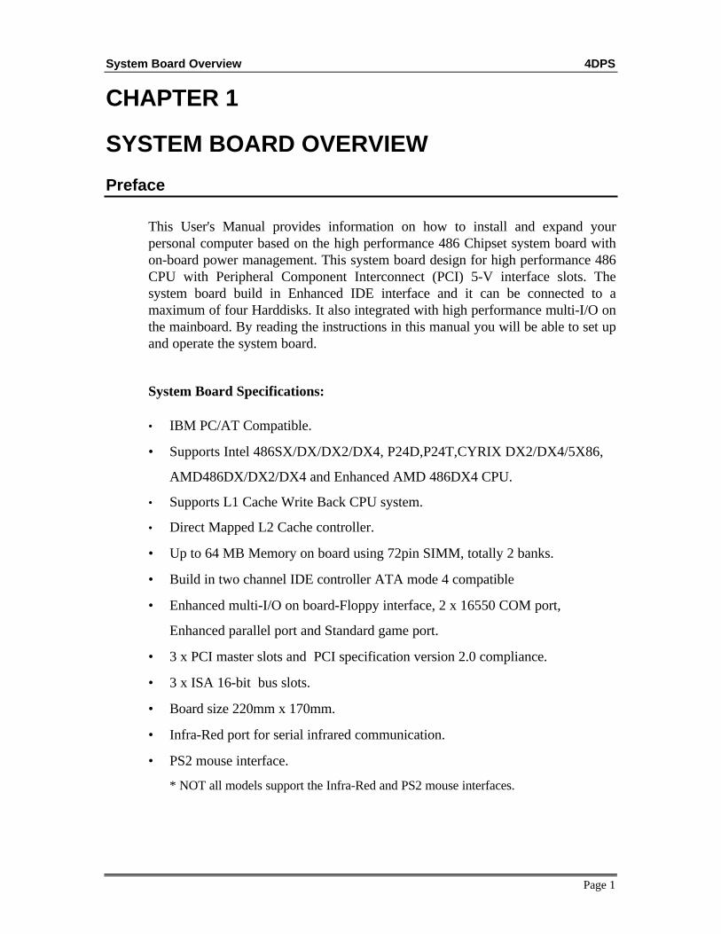
Preface
This User's Manual provides information on how to install and expand yourpersonal computer based on the high performance 486 Chipset system board withon-board power management. This system board design for high performance 486CPU with Peripheral Component Interconnect (PCI) 5-V interface slots. Thesystem board build in Enhanced IDE interface and it can be connected to amaximum of four Harddisks. It also integrated with high performance multi-I/O onthe mainboard. By reading the instructions in this manual you will be able to set upand operate the system board.
• Up to 64 MB Memory on board using 72pin SIMM, totally 2 banks.
• Build in two channel IDE controller ATA mode 4 compatible
• Enhanced multi-I/O on board-Floppy interface, 2 x 16550 COM port,
Enhanced parallel port and Standard game port.
• 3 x PCI master slots and PCI specification version 2.0 compliance.
• 3 x ISA 16-bit bus slots.
• Board size 220mm x 170mm.
• Infra-Red port for serial infrared communication.
• PS2 mouse interface.
* NOT all models support the Infra-Red and PS2 mouse interfaces.
System Board Overview 4DPS
Page 2
Layout Of System Board
SIS85C496
SIS85C497
W8378F
SYSTEMBIOS
PCI3 PCI2 PCI1
SIMM
1
SIMM
2
P1
BT1 KB1
U31
U32
U33
U34
U7
CPUSOCKET
W83768F
J2
JP9
JP11JP7
JP17
JP28
JP21
JP20
J6
JP18JP19
JP4
J1
J5
J9J3
JP26
PR
INT
ER
JP29
FLO
PP
Y J10
CO
M B
J11
CO
M A
J12
GA
ME
J13
PR
IMA
RY
IDE
J8
SE
CO
ND
AR
Y ID
E J7
TAGRAM
CACHE RAM
JP22JP
27
JP30
JP10
JP3
JP15
JP14
JP6
IR JP
23
MOUSEKEYBOARDBIOS0
Drawing no. : LO-4DPS-0020A
The system board size is 220 x 170 mm.
Jumper Settings 4DPS
Page 3
Jumper Settings
CPU SELECT ( * Default jumper setting for Enhanced AMD 486DX4-100 )JP6 JP14 JP15 JP3 JP10JP9 JP11 JP7 JP17
INTEL CPUIntel SX
JP27
JP30
JP10
JP3
JP15
JP14
JP6
JP9
JP11JP7
JP17
JP28
Intel SL-Enhanced SX/SX2
JP27
JP30
JP10
JP3
JP15
JP14
JP6
JP9
JP11JP7
JP17
JP28
Intel DX/DX2-66
JP27
JP30
JP10
JP3
JP15
JP14
JP6
JP9
JP11JP7
JP17
JP28
Intel SL-Enhanced DX/DX2
JP27
JP30
JP10
JP3
JP15
JP14
JP6
JP9
JP11JP7
JP17
JP28
Intel DX4 ( wirte through )
JP27
JP30
JP10
JP3
JP15
JP14
JP6
JP9
JP11JP7
JP17
JP28
Intel P24D
JP17
JP27
JP30
JP10
JP3
JP15
JP14
JP6
JP9
JP11JP7
JP28
Intel Pentium Overdrive (P24T)
JP27
JP30
JP10
JP3
JP15
JP14
JP6
JP9
JP11JP7
JP17
JP28
INTEL DX4 (write back)
JP17
JP2
7
JP3
0
JP1
0JP
3JP
15
JP1
4JP
6
JP9
JP11JP7
JP28
Jumper Settings 4DPS
Page 4
Jumper Settings
CPU SELECT ( * Default jumper setting for Enhanced AMD 486DX4-100 )JP6 JP14 JP15 JP3 JP10JP9 JP11 JP7 JP17
AMD CPUAMD DX/DX2/DX4
JP27
JP30
JP10
JP3
JP15
JP14
JP6
JP9
JP11JP7
JP17
JP28
Enhanced AMD DX4-100/DX4-120 *
JP17
JP27
JP30
JP10
JP3
JP15
JP14
JP6
JP9
JP11JP7
JP28
AMD 5X86
JP17
JP2
7
JP3
0
JP1
0JP
3JP
15
JP1
4JP
6
JP9
JP11JP7
JP28
Cyrix CPUCyrix 486S
JP27
JP30
JP10
JP3
JP15
JP14
JP6
JP9
JP11JP7
JP17
JP28
Cyrix 486DX2/DX4
JP27
JP30
JP10
JP3
JP15
JP14
JP6
JP9
JP11JP7
JP17
JP28
Cyrix 5X86
JP27
JP30
JP9
JP11JP7
JP17
JP28
JP10
JP3
JP15
JP14
JP6
Cyrix 486 DX4 V
JP27
JP30
JP9
JP11JP7
JP17
JP28
JP10
JP3
JP15
JP14
JP6
CPU Voltage SelectJP30 JP27 JP28
Voltage 3.3V * 5V
Setting
JP27
JP30
JP28 JP27
JP30
JP28
Jumper Settings 4DPS
Page 5
Jumper Settings
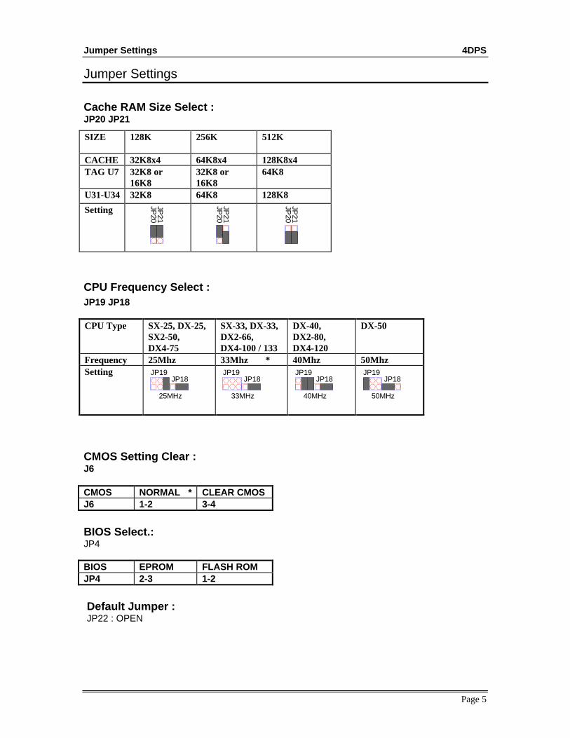
Cache RAM Size Select :JP20 JP21
SIZE 128K 256K 512K
CACHE 32K8x4 64K8x4 128K8x4TAG U7 32K8 or
16K832K8 or16K8
64K8
U31-U34 32K8 64K8 128K8
Setting
JP21
JP20
JP21
JP20
JP21
JP20
CPU Frequency Select :JP19 JP18
CPU Type SX-25, DX-25,SX2-50,DX4-75
SX-33, DX-33,DX2-66,DX4-100 / 133
DX-40,DX2-80,DX4-120
DX-50
Frequency 25Mhz 33Mhz * 40Mhz 50MhzSetting
JP18JP19
25MHz
JP18JP19
33MHz 40MHz
JP18JP19
JP18JP19
50MHz
CMOS Setting Clear :J6
CMOS NORMAL * CLEAR CMOSJ6 1-2 3-4
BIOS Select.:JP4
BIOS EPROM FLASH ROMJP4 2-3 1-2
Default Jumper : JP22 : OPEN
SIMM RAM SETTING 4DPS
Page 6
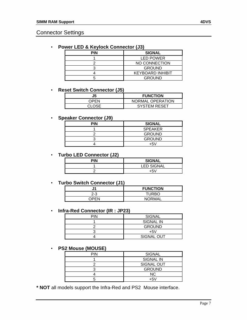
Connector Settings
Connector Descriptions
Description ConnectorsSerial Port 1 / 2 COM A (J12) / COM B (J11)Parallel Port JP29Game Port GAME (J13)Floppy Disk Connector J10PCI Primary IDE Hard Disk Connector IDE1 (J8)PCI Secondary IDE Hard Disk Connector IDE2 (J7)PCI IDE LED IDE LED (JP26)Power Supply Connector P1Power LED & Keylock J3Reset Switch RST J5Speaker J9Turbo LED TB LED (J2)Turbo Switch J1Infra-Red Connector ( Optional ) IR (JP23)PS2 Mouse ( Optional ) MOUSE
1 LED POWER2 NO CONNECTION3 GROUND4 KEYBOARD INHIBIT5 GROUND
• Reset Switch Connector (J5)J5 FUNCTION
OPEN NORMAL OPERATIONCLOSE SYSTEM RESET
• Speaker Connector (J9)PIN SIGNAL
1 SPEAKER2 GROUND3 GROUND4 +5V
• Turbo LED Connector (J2)PIN SIGNAL
1 LED SIGNAL2 +5V
• Turbo Switch Connector (J1)J1 FUNCTION2-3 TURBO
OPEN NORMAL
• Infra-Red Connector (IR : JP23)PIN SIGNAL
1 SIGNAL IN2 GROUND3 +5V4 SIGNAL OUT
• PS2 Mouse (MOUSE)PIN SIGNAL
1 SIGNAL IN2 SIGNAL OUT3 GROUND4 NC5 +5V
* NOT all models support the Infra-Red and PS2 Mouse interface.
SIMM RAM SETTING 4DPS
Page 8
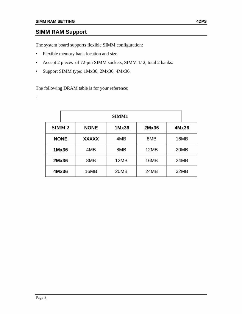
SIMM RAM Support
The system board supports flexible SIMM configuration:
• Flexible memory bank location and size.
• Accept 2 pieces of 72-pin SIMM sockets, SIMM 1/ 2, total 2 banks.
• Support SIMM type: 1Mx36, 2Mx36, 4Mx36.
The following DRAM table is for your reference:
.
SIMM1
SIMM 2 NONE 1Mx36 2Mx36 4Mx36
NONE XXXXX 4MB 8MB 16MB
1Mx36 4MB 8MB 12MB 20MB
2Mx36 8MB 12MB 16MB 24MB
4Mx36 16MB 20MB 24MB 32MB
AWARD BIOS SETUP 4DPS
Page 9
CHAPTER 2AWARD BIOS SETUP
Award’s BIOS has a built-in Setup program that allows users to modify the basic system configuration.This type of information is stored in battery-backed RAM so that it retains the setup information when thepower is turned off. This chapter explains the setup utility for the Award BIOS.
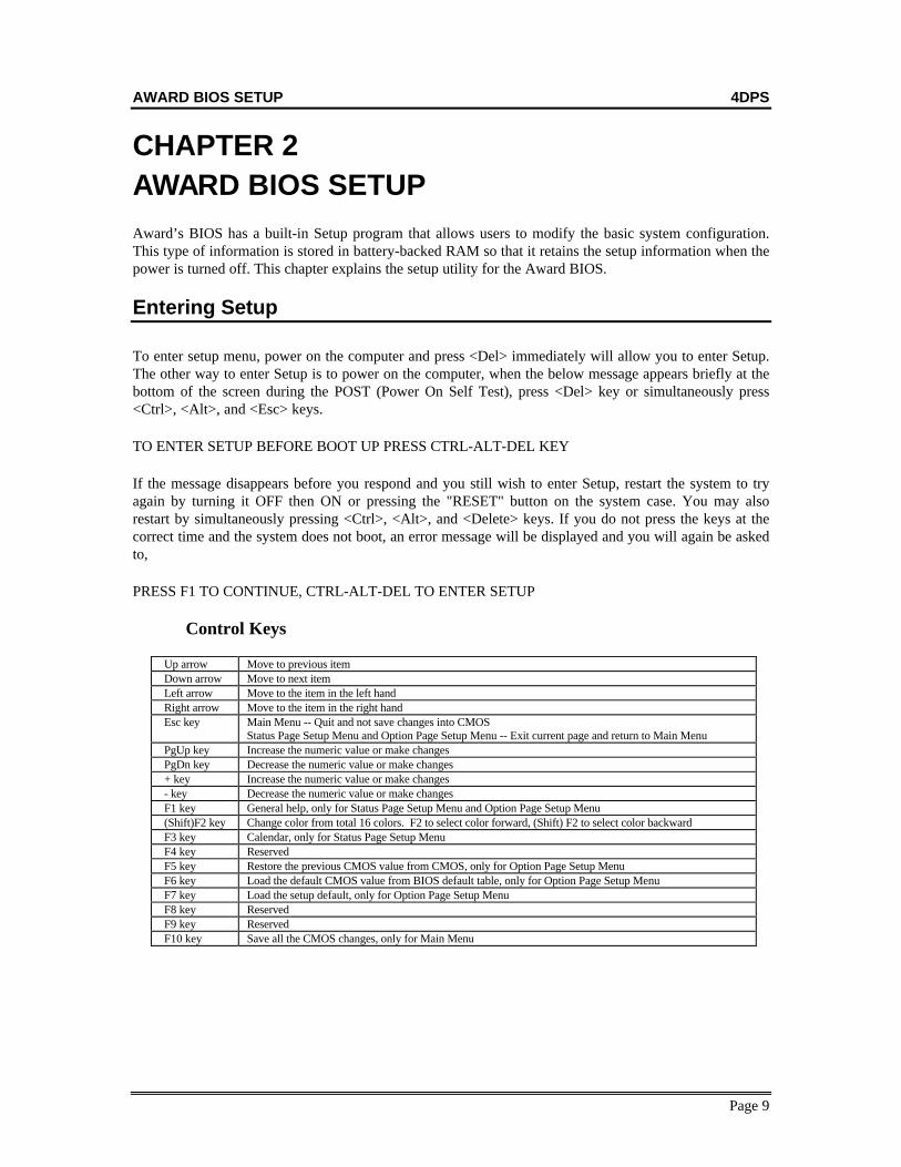
Entering Setup
To enter setup menu, power on the computer and press <Del> immediately will allow you to enter Setup.The other way to enter Setup is to power on the computer, when the below message appears briefly at thebottom of the screen during the POST (Power On Self Test), press <Del> key or simultaneously press<Ctrl>, <Alt>, and <Esc> keys.
TO ENTER SETUP BEFORE BOOT UP PRESS CTRL-ALT-DEL KEY
If the message disappears before you respond and you still wish to enter Setup, restart the system to tryagain by turning it OFF then ON or pressing the "RESET" button on the system case. You may alsorestart by simultaneously pressing <Ctrl>, <Alt>, and <Delete> keys. If you do not press the keys at thecorrect time and the system does not boot, an error message will be displayed and you will again be askedto,
PRESS F1 TO CONTINUE, CTRL-ALT-DEL TO ENTER SETUP
Control Keys
Up arrow Move to previous itemDown arrow Move to next itemLeft arrow Move to the item in the left handRight arrow Move to the item in the right handEsc key Main Menu -- Quit and not save changes into CMOS
Status Page Setup Menu and Option Page Setup Menu -- Exit current page and return to Main MenuPgUp key Increase the numeric value or make changesPgDn key Decrease the numeric value or make changes+ key Increase the numeric value or make changes- key Decrease the numeric value or make changesF1 key General help, only for Status Page Setup Menu and Option Page Setup Menu(Shift)F2 key Change color from total 16 colors. F2 to select color forward, (Shift) F2 to select color backwardF3 key Calendar, only for Status Page Setup MenuF4 key ReservedF5 key Restore the previous CMOS value from CMOS, only for Option Page Setup MenuF6 key Load the default CMOS value from BIOS default table, only for Option Page Setup MenuF7 key Load the setup default, only for Option Page Setup MenuF8 key ReservedF9 key ReservedF10 key Save all the CMOS changes, only for Main Menu
AWARD BIOS SETUP 4DPS
Page 10
Getting Help
Main MenuThe on-line description of the highlighted setup function is displayed at the bottom of the screen.
Status Page Setup Menu/Option Page Setup MenuPress F1 to pop up a small help window that describes the appropriate keys to use and the possibleselections for the highlighted item. To exit the Help Window press <Esc>.
The Main Menu
Once you enter Award BIOS CMOS Setup Utility, the Main Menu (Figure 1) will appear on thescreen. The Main Menu allows you to select from ten setup functions and two exit choices. Use arrowkeys to select among the items and press <Enter> to accept or enter the sub-menu.
Figure 1. Main Setup Menu ÚÄÄÄÄÄÄÄÄÄÄÄÄÄÄÄÄÄÄÄÄÄÄÄÄÄÄÄÄÄÄÄÄÄÄÄÄ-ÄÄÄÄÄÄÄÄÄÄÄÄÄÄÄÄÄÄÄÄÄÄÄÄÄÄÄÄÄÄÄÄÄÄÄÄÄ¿ ³ CMOS SETUP UTILITY ³ ³ AWARD SOFTWARE, INC. ³ ÃÄÄÄÄ-ÄÄÄÄÄÄÄÄÄÄÄÄÄÄÄÄÄÄÄÄÄÄÄÄÄÄÄÄÄÄÄÂÄÄÄÄÄÄÄÄÄÄÄÄÄÄÄÄÄÄÄÄÄÄÄÄÄÄÄÄÄÄÄÄÄÄÄÄÄ´ ³ STANDARD CMOS SETUP ³ PASSWORD ³ ³ BIOS FEATURES SETUP ³ IDE HDD AUTO DETECTION ³ ³ CHIPSET FEATURES SETUP ³ SAVE & EXIT SETUP ³ ³ POWER MANAGEMENT SETUP ³ EXIT WITHOUT SAVING ³ ³ PCI CONFIGURATION SETUP ³ ³ ³ LOAD BIOS DEFAULTS ³ ³ ³ LOAD SETUP DEFAULTS ³ ³ ÃÄÄÄÄÄ-ÄÄÄÄÄÄÄÄÄÄÄÄÄÄÄÄÄÄÄÄÄÄÄÄÄÄÄÄÄÄÁÄÄÄÄÄÄÄÄÄÄÄÄÄÄÄÄÄÄÄÄÄÄÄÄÄÄÄÄÄÄÄÄÄÄÄÄÄ´ ³ ESC : Quit ↑ ↓ → ← : Select Item ³ ³ F10 : Save & Exit Setup (Shift)F2 : Change Color ³ ÀÄÄÄÄÄÄÄÄÄÄÄÄÄÄÄÄÄÄÄÄÄÄÄÄÄÄÄÄÄÄÄÄÄÄÄÄÄÄÄÄÄÄÄÄÄÄÄÄÄÄÄÄÄÄÄÄÄÄÄÄÄÄÄÄÄÄÄÄÄÄÄÄÄÄÙ
Standard CMOS setupThis setup page includes all the items in a standard compatible BIOS.
BIOS features setupThis setup page includes all the items of Award special enhanced features.
Chipset features setupThis setup page includes all the items of chipset special features.
Power management setup This setup page includes all the items of green features.
AWARD BIOS SETUP 4DPS
Page 11
The Main Menu
PCI configuration setup This setup page includes all the items of PCI INT, IRQ, IDE configs.
Load BIOS defaultsBIOS defaults indicates the most appropriate value of the system parameter which the system wouldbe in minimum performance.
Load setup defaultsChipset defaults indicates the values required by the system for the maximum performance.
Password settingChange, set, or disable password. It allows you to limit access to the system and Setup.
IDE HDD auto detectionAutomatically configure hard disk parameters.
Save & exit setupSave CMOS value changes to CMOS and exit setup.
Exit without saveAbandon all CMOS value changes and exit setup.
Standard CMOS Setup Menu 4DPS
Page 12
Standard CMOS Setup Menu
The items in Standard CMOS Setup Menu are divided into 10 categories. Each category includes no, oneor more than one setup items. Use the arrow keys to highlight the item and then use the <PgUp> or<PgDn> keys to select the value you want in each item.
Figure 2 Standard CMOS Setup Menu
ÚÄÄÄÄÄÄÄÄÄÄÄÄÄÄÄÄÄÄÄÄÄÄÄÄÄÄÄÄÄÄÄÄÄÄÄÄ-ÄÄÄÄÄÄÄÄÄÄÄÄÄÄÄÄÄÄÄÄÄÄÄÄÄÄÄÄÄÄÄÄÄÄÄÄÄ¿ ³ Date (mm:dd:yy) : Web, Dec 20 1994 ³ ³ Time (hh:mm:ss) : 10 : 27 : 52 ³ ³ ³ ³ HARD DISKS TYPE SIZE CYLS HEAD PRECOMP LANDZ SECTOR MODE ³ ³ ³ ³ PRIMARY MASTER :None 0 0 0 0 0 0 ³ ³ PRIMARY Slave :None 0 0 0 0 0 0 ³ ³ Secondary Master :None 0 0 0 0 0 0 ³ ³ Secondary Slave :None 0 0 0 0 0 0 ³ ³ ³ ³ Drive A : None ÚÄÄÄÄÄÄÄÄÄÄÄÄÄÄÄÄÄÄÄÄÄÄÄÄÄÄÄÄÄÄÄ´ ³ Drive B : None ³ Base Memory: 640K ³ ³ ³ Extended Memory: 7168K ³ ³ Video : EGA/VGA ³ Other Memory: 384K ³ ³ Halt On : All Errors ³ ÄÄÄÄÄÄÄÄÄÄÄÄÄÄÄÄÄÄÄÄÄÄÄÄÄ ³ ³ ³ Total Memory: 8192 ³ ÃÄÄÄÄÄ-ÄÄÄÄÄÄÄÄÄÄÄÄÄÄÄÄÄÄÄÄÄÄÄÄÄÄÄÄÄÄÄÄÄÄÄÄÁÄÄÄÄÄÄÄÄÄÄÄÄÄÄÄÄÄÄÄÄÄÄÄÄÄÄÄÄÄÄÄ´ ³ ESC : Quit ↑ ↓ → ← : Select Item PU/PD/+/- : Modify ³ ³ F1 : Help (Shift)F2 : Change Color ³ ÀÄÄÄÄÄÄÄÄÄÄÄÄÄÄÄÄÄÄÄÄÄÄÄÄÄÄÄÄÄÄÄÄÄÄÄÄÄÄÄÄÄÄÄÄÄÄÄÄÄÄÄÄÄÄÄÄÄÄÄÄÄÄÄÄÄÄÄÄÄÄÄÄÄÄÙ
Date & TimeEnter current Date & Time to set system clock. The date format is <day>, <date> <month> <year>and the time format is <hour> <minute> <second>. The time is calculated based on the 24-hourmilitary-time clock. Press <F3> to show the calendar.
Standard CMOS Setup 4DPS
Page 13
Standard CMOS Setup Menu
Drive C type/Drive D typeThe categories identify the types of hard disk drive C or drive D that have been installed in thecomputer. There are 46 predefined types and a user definable type. Type 1 to Type 46 arepredefined. Type User is user-definable.
Press PgUp or PgDn to select a numbered hard disk type or type the number and press <Enter>.Note that the specifications of your drive must match with the drive table. The hard disk will notwork properly if you enter improper information for this category. If your hard disk drive type isnot matched or listed, you can use Type User to define your own drive type manually.
If you select Type “User”, related information is asked to be entered to the following items. Enterthe information directly from the keyboard and press <Enter>. This information should be providedin the documentation from your hard disk vendor or the system manufacturer.
There are the option of Type “AUTO” and Mode “AUTO” to auto detect the hard disk type and thehard disk mode (Normal, LBA and Large).
If a hard disk has not been installed select NONE and press <Enter>.
Note: Mode Setting For Hard Disk Larger than 528MB
The Mode settings are for IDE hard disks only. You can ignore this item for MFM and ESDIdrivers. There are three entries you can select from in the mode field, ”Normal”, ”Large” and“LBA”.
Set Mode to the Normal settings for IDE hard disk drives smaller than 528MB. Use the LBAsetting for drives over 528MB that use Logical Block Addressing mode to allow larger IDE harddisks. The Large setting is for drives over 528MB that do not use the LBA mode. This type of drivecan only be used with MS-DOS and is uncommon. The majority of IDE drives over 528MB use theLBA mode.
Drive A type/Drive B typeThe category identifies the types of floppy disk drive A or drive B that have been installed in thecomputer.
VideoThe category selects the type of adapter used for the primary system monitor that must match yourvideo display card and monitor. Although secondary monitors are supported, you do not have toselect the type in Setup.
Standard CMOS Setup Menu 4DPS
Page 14
Standard CMOS Setup Menu
Error haltThe category determines whether the computer will stop if an error is detected during power up.
MemoryThe category is display-only which is determined by POST (Power On Self Test) of the BIOS.
Base MemoryThe POST of the BIOS will determine the amount of base (or conventional) memory installed inthe system. The value of the base memory is typically 512K for systems with 512K memoryinstalled on the motherboard, or 640K for systems with 640K or more memory installed on themotherboard.
Extended MemoryThe BIOS determines how much extended memory is present during the POST. This is the amountof memory located above 1MB in the CPU's memory address map.
Expanded MemoryExpanded Memory is memory defined by the Lotus/Intel/Microsoft (LIM) standard as EMS. Manystandard DOS applications cannot utilize memory above 640K, the Expanded MemorySpecification (EMS) swaps memory which is not utilized by DOS with a section, or frame, so theseapplications can access all of the system memory. Memory can be swapped by EMS is usually 64Kwithin 1MB or memory above 1MB, depending on the chipset design.
Other MemoryThis refers to the memory located in the 640K to 1024K address space. This is memory that can beused for different applications. DOS uses this area to load device drivers to keep as much basememory free for application programs. Most use for this area is Shadow RAM.
BIOS Features Setup 4DPS
Page 15
BIOS Features Setup Menu
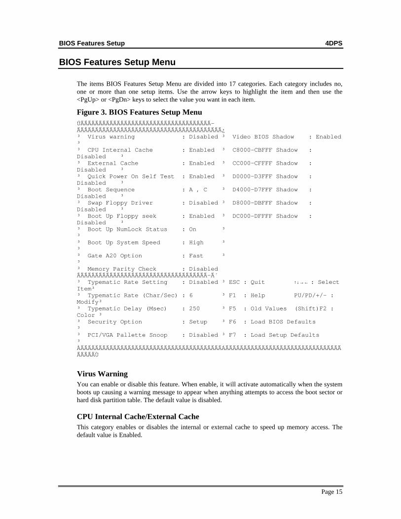
The items BIOS Features Setup Menu are divided into 17 categories. Each category includes no,one or more than one setup items. Use the arrow keys to highlight the item and then use the<PgUp> or <PgDn> keys to select the value you want in each item.
Figure 3. BIOS Features Setup MenuÚÄÄÄÄÄÄÄÄÄÄÄÄÄÄÄÄÄÄÄÄÄÄÄÄÄÄÄÄÄÄÄÄÄÄÄÄ-ÄÄÂÄÄÄÄÄÄÄÄÄÄÄÄÄÄÄÄÄÄÄÄÄÄÄÄÄÄÄÄÄÄÄÄÄÄÄÄÄ¿³ Virus warning : Disabled ³ Video BIOS Shadow : Enabled³³ CPU Internal Cache : Enabled ³ C8000-CBFFF Shadow :Disabled ³³ External Cache : Enabled ³ CC000-CFFFF Shadow :Disabled ³³ Quick Power On Self Test : Enabled ³ D0000-D3FFF Shadow :Disabled ³³ Boot Sequence : A , C ³ D4000-D7FFF Shadow :Disabled ³³ Swap Floppy Driver : Disabled ³ D8000-DBFFF Shadow :Disabled ³³ Boot Up Floppy seek : Enabled ³ DC000-DFFFF Shadow :Disabled ³³ Boot Up NumLock Status : On ³³³ Boot Up System Speed : High ³³³ Gate A20 Option : Fast ³³³ Memory Parity Check : DisabledÃÄÄÄÄÄÄÄÄÄÄÄÄÄÄÄÄÄÄÄÄÄÄÄÄÄÄÄÄÄÄÄÄÄÄÄ-Ä´³ Typematic Rate Setting : Disabled ³ ESC : Quit ↑↓→← : SelectItem³³ Typematic Rate (Char/Sec) : 6 ³ F1 : Help PU/PD/+/- :Modify³³ Typematic Delay (Msec) : 250 ³ F5 : Old Values (Shift)F2 :Color ³³ Security Option : Setup ³ F6 : Load BIOS Defaults³³ PCI/VGA Pallette Snoop : Disabled ³ F7 : Load Setup Defaults³ÀÄÄÄÄÄÄÄÄÄÄÄÄÄÄÄÄÄÄÄÄÄÄÄÄÄÄÄÄÄÄÄÄÄÄÄÄÄÄÄÁÄÄÄÄÄÄÄÄÄÄÄÄÄÄÄÄÄÄÄÄÄÄÄÄÄÄÄÄÄÄÄÄÄÄÄÄÄÙ
Virus WarningYou can enable or disable this feature. When enable, it will activate automatically when the systemboots up causing a warning message to appear when anything attempts to access the boot sector orhard disk partition table. The default value is disabled.
CPU Internal Cache/External CacheThis category enables or disables the internal or external cache to speed up memory access. Thedefault value is Enabled.
BIOS Features Setup 4DPS
Page 16
Quick Power On Self TestThis category speeds up Power On Self Test (POST) after you power on the computer. If it is set toEnable, BIOS will shorten or skip some check items during POST. The default value is disabled.
Boot SequenceThis category determines which drive computer searches first for the disk operating system (i.e.,DOS). Default value is A,C.
Swap Floppy DriveThis feature allows you to enable the system swap floppy function. When this function enables, thesystem will assign the Drive A as Drive B, and vice versa.
Boot Up Floppy SeekIf enabled, the BIOS searches for floppy disk drive to determine if it is 40 or 80 tracks. If disabledBIOS will not search for the type of floppy disk drive by track number. Note that there will not beany warning message if the drive installed is 360K.
BIOS Features Setup 4DPS
Page 17
BIOS Features Setup Menu
Boot Up NumLock StatusIt selects the option to turn on/off Num Lock when the system is powered on so the end user can usethe arrow keys on both the numeric keypad and the keyboard. The default value is On.
Boot Up System SpeedIt selects the boot up system speed. The default setting is Fast.
Gate A20 OptionThe default setting of the Gate A20 is Fast.
Memory Parity CheckThis option enables parity error checking for system RAM. The default setting is Enable.
Typematic Rate SettingTypematic Rate sets the rate at which characters on the screen at which characters on the screenrepeat. The default setting is Disabled.
Typematic Rate (Chars/Sec)Typematic rate sets the rate at which characters on the screen repeat when a key is pressed and helddown. You can select 6-30 characters per second. The default setting is 6.
Typematic Delay (Msec)When holding down a key, the time between the first and second character display. you specifiednumbers of times of character repeat on the screen. The default setting is 250.
Security OptionThis category allows you to limit access to the system and Setup, or just to Setup. When you selectsystem, the system will not boot and access to Setup will be denied if the correct password is notentered at the prompt. If you select Setup, the system will boot but access to Setup will be denied ifthe correct password is not entered at the prompt. The default setting is Setup.
PCI/VGA Palette SnoopThis option controls the system to access the PCI VGA card plalette register. In general, this optionis disabled. However, you may need to enable this option for some VGA card which have incorrectcolor displayed problem on some software application..
VIDEO BIOS ShadowThe system BIOS is automatically shadowed .The default setting for the “Video BIOS Shadow” is “Enabled”. It determines whether video BIOSwill be copied to RAM, however, it is optional from chipset design. Video Shadow will increase thevideo speed.
C8000 - CFFFF Shadow/E8000 - EFFFF ShadowThese categories determine whether optional ROM will be copied to RAM by 16K byte. You canenable the optional shadow or you can disable it. The default setting is disabled.
Chipset Features Setup 4DPS
Page 18
Chipset Features Setup Menu
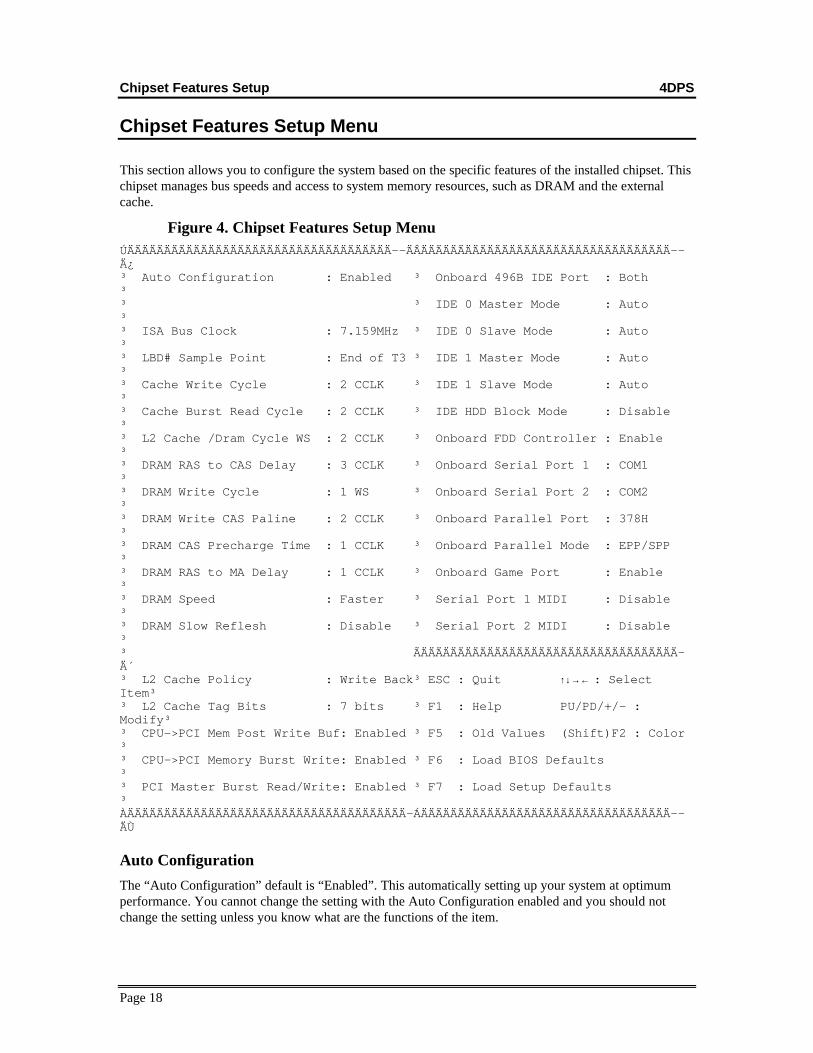
This section allows you to configure the system based on the specific features of the installed chipset. Thischipset manages bus speeds and access to system memory resources, such as DRAM and the externalcache.
Figure 4. Chipset Features Setup MenuÚÄÄÄÄÄÄÄÄÄÄÄÄÄÄÄÄÄÄÄÄÄÄÄÄÄÄÄÄÄÄÄÄÄÄÄÄ--ÄÂÄÄÄÄÄÄÄÄÄÄÄÄÄÄÄÄÄÄÄÄÄÄÄÄÄÄÄÄÄÄÄÄÄÄ--Ä¿³ Auto Configuration : Enabled ³ Onboard 496B IDE Port : Both³³ ³ IDE 0 Master Mode : Auto³³ ISA Bus Clock : 7.159MHz ³ IDE 0 Slave Mode : Auto³³ LBD# Sample Point : End of T3 ³ IDE 1 Master Mode : Auto³³ Cache Write Cycle : 2 CCLK ³ IDE 1 Slave Mode : Auto³³ Cache Burst Read Cycle : 2 CCLK ³ IDE HDD Block Mode : Disable³³ L2 Cache /Dram Cycle WS : 2 CCLK ³ Onboard FDD Controller : Enable³³ DRAM RAS to CAS Delay : 3 CCLK ³ Onboard Serial Port 1 : COM1³³ DRAM Write Cycle : 1 WS ³ Onboard Serial Port 2 : COM2³³ DRAM Write CAS Paline : 2 CCLK ³ Onboard Parallel Port : 378H³³ DRAM CAS Precharge Time : 1 CCLK ³ Onboard Parallel Mode : EPP/SPP³³ DRAM RAS to MA Delay : 1 CCLK ³ Onboard Game Port : Enable³³ DRAM Speed : Faster ³ Serial Port 1 MIDI : Disable³³ DRAM Slow Reflesh : Disable ³ Serial Port 2 MIDI : Disable³³ ÃÄÄÄÄÄÄÄÄÄÄÄÄÄÄÄÄÄÄÄÄÄÄÄÄÄÄÄÄÄÄÄÄÄÄÄ-Ä´³ L2 Cache Policy : Write Back³ ESC : Quit ↑↓→← : SelectItem³³ L2 Cache Tag Bits : 7 bits ³ F1 : Help PU/PD/+/- :Modify³³ CPU->PCI Mem Post Write Buf: Enabled ³ F5 : Old Values (Shift)F2 : Color³³ CPU->PCI Memory Burst Write: Enabled ³ F6 : Load BIOS Defaults³³ PCI Master Burst Read/Write: Enabled ³ F7 : Load Setup Defaults³ÀÄÄÄÄÄÄÄÄÄÄÄÄÄÄÄÄÄÄÄÄÄÄÄÄÄÄÄÄÄÄÄÄÄÄÄÄÄÄ-ÁÄÄÄÄÄÄÄÄÄÄÄÄÄÄÄÄÄÄÄÄÄÄÄÄÄÄÄÄÄÄÄÄÄÄ--ÄÙ
Auto Configuration
The “Auto Configuration” default is “Enabled”. This automatically setting up your system at optimumperformance. You cannot change the setting with the Auto Configuration enabled and you should notchange the setting unless you know what are the functions of the item.
Chipset Features Setup 4DPS
Page 19
The on-board multi-I/O configed on this setup menu. There are different options for the I/O interface. Youcan enable or disable the on-board I/O device individually or you can change the default configurationfrom this menu.
L2 Cache Policy
You can select the external cache to write back or write trough mode at this item.
L2 Cache Tag Bits
Set the Tag Bits to “7 bits” , if you select the external cache to write back mode.Set the Tag Bits to “8 bits” , if you select the external cache to write through mode.
CPU->PCI Mem Post Write Buf ,CPU->PCI Memory Burst Write
CPU to PCI memory post write & burst write control. The default is enabled.
PCI Master Burst Read/Write
PCI master burst read/write control. The default is enabled.
Chipset Features Setup 4DPS
Page 20
Chipset Features Setup Menu
On board 496B IDE portThe primary and secondary IDE port can be enabled or disabled by this option.
IDE 0(1) master(slave) modeYou can select the Normal, LBA, Large mode for the IDE port. Default is Auto means that the IDEmode is automatically detected. ( 0 : Primary 1 : Secondary )
IDE HDD block modeYou can enable the block mode transfer to transfer data between the hard disk and IDE interface.
Onboard FDD ControllerThe on-board floppy disk controller can be enabled or disabled. You can select enabled or disabled in thisoption.
Onboard serial port 1(2)You can config the on-board serial port as COM1-COM4 or select “none” to disable the serial port.
Onboard parallel portThe on-board parallel port configed as LPT1 (378), LPT2 (278) or select “none” to disable the parallelport.
Onboard parallel port modeYou can select ESP (Standard mode), EPP(Enhanced mode) and ECP(Extended mode) for parallel portmode in this menu.
Onboard game portThe on-board game port can be enabled or disabled by this option.
Serial port 1(2) MIDIYou can enable or disable the serial MIDI (Musical Instrument Digital Interface) support by this option.
Power Management 4DPS
Page 21
Power Management Setup
Power Management setup controls the system board’s “green” features. This feature enhance 486microprocessor family with the energy-efficient technology. The setup screen is shown in figure 5.
Figure 5. Power Management Setup Menu
ÚÄÄÄÄÄÄÄÄÄÄÄÄÄÄÄÄÄÄÄÄÄÄÄÄÄÄÄÄÄÄÄÄÄÄÄÄÄÄÂÄÄÄÄÄÄÄÄÄÄÄÄÄÄÄÄÄÄÄÄÄÄÄÄÄÄÄÄÄÄÄÄÄÄÄÄÄÄ¿ ³ Power Management : Disabled ³³ ³ PM Control by APM : Yes ³³ ³ Video off Method : V/H SYNC+Blank³³ ³ ³³ ³ ** PM Timers ** ³³ ³ HDD Off After : DisableÃÄÄÄÄÄÄÄÄÄÄÄÄÄÄÄÄÄÄÄÄÄÄÄÄÄÄÄÄÄÄÄÄÄÄÄÄÄÄ´ ³ Green Mode : Disable ³ ESC : Quit ↑↓→← Select Item³ ³ ³ F1 : Help PU/PD/+/- : Modify³ ³ ³ F5 : Old Values (Shift)F2 : Color³ ³ ³ F6 : Load BIOS Defaults³ ³ ³ F7 : Load Setup Defaults³
Power Management“Power Management” is the master control for the power saving features, including HDD power down,Doze, Standby and suspend Modes and the I/O Device Timer, that together form the hard-ware powerconservation scheme. There are three options:User Defined - Allows you to configure the power conservation features yourself.Disable - Turn off all the power conservation features.
PM Control by APMThis feature is automatically set to “ON”, the system BIOS will wait for APM prompt before it enters theGREEN mode.NOTE : If APM is installed, & if there is a task running, event the timer is time out, the APM will not prompt the
BIOS to put the system into any power saving mode!
Power Management 4DPS
Page 22
VGA Off MethodThere are two options you can choose for which mode to turn off the VGA display.Blank Screen - The system will blank the screen only.V/H SYNC + Blank - Choose this mode if your system using the monitor with power
management feature. In addition of the blank screen, the system will turnoff the horizontal and vertical sync signal. Most monitor will turn offitself if these signal is inactive.
HDD Off Timer“HDD Off Timer” specifies the period to cause an IDE hard disk to “spin down” if it is not accessed. Thedisk returns to full speed the next time it is accessed. Settings range from “10 Min” to “15 Min”, and“Disabled”.
Green ModeTimer“Green Mode Timer” specifies the period to cause the system enter power management mode. Theavailable Settings range is from “20 Min” to “40 Min”, and “Disabled”.
PCI Configuration 4DPS
Page 23
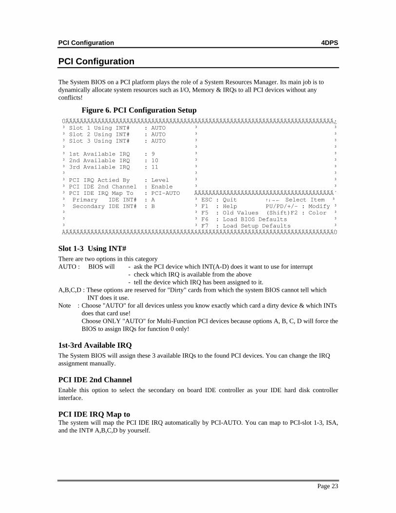
PCI Configuration
The System BIOS on a PCI platform plays the role of a System Resources Manager. Its main job is todynamically allocate system resources such as I/O, Memory & IRQs to all PCI devices without anyconflicts!
Figure 6. PCI Configuration Setup ÚÄÄÄÄÄÄÄÄÄÄÄÄÄÄÄÄÄÄÄÄÄÄÄÄÄÄÄÄÄÄÄÄÄÄÄÄÂÄÄÄÄÄÄÄÄÄÄÄÄÄÄÄÄÄÄÄÄÄÄÄÄÄÄÄÄÄÄÄÄÄÄÄÄÄÄ¿ ³ Slot 1 Using INT# : AUTO ³ ³ ³ Slot 2 Using INT# : AUTO ³ ³ ³ Slot 3 Using INT# : AUTO ³ ³ ³ ³ ³ ³ 1st Available IRQ : 9 ³ ³ ³ 2nd Available IRQ : 10 ³ ³ ³ 3rd Available IRQ : 11 ³ ³ ³ ³ ³ ³ PCI IRQ Actied By : Level ³ ³ ³ PCI IDE 2nd Channel : Enable ³ ³ ³ PCI IDE IRQ Map To : PCI-AUTO ÃÄÄÄÄÄÄÄÄÄÄÄÄÄÄÄÄÄÄÄÄÄÄÄÄÄÄÄÄÄÄÄÄÄÄÄÄÄÄ´ ³ Primary IDE INT# : A ³ ESC : Quit ↑↓→← Select Item ³ ³ Secondary IDE INT# : B ³ F1 : Help PU/PD/+/- : Modify ³ ³ ³ F5 : Old Values (Shift)F2 : Color ³ ³ ³ F6 : Load BIOS Defaults ³ ³ ³ F7 : Load Setup Defaults ³ ÀÄÄÄÄÄÄÄÄÄÄÄÄÄÄÄÄÄÄÄÄÄÄÄÄÄÄÄÄÄÄÄÄÄÄÄÄÁÄÄÄÄÄÄÄÄÄÄÄÄÄÄÄÄÄÄÄÄÄÄÄÄÄÄÄÄÄÄÄÄÄÄÄÄÄÄÙ
Slot 1-3 Using INT#There are two options in this categoryAUTO : BIOS will - ask the PCI device which INT(A-D) does it want to use for interrupt - check which IRQ is available from the above - tell the device which IRQ has been assigned to it.A,B,C,D : These options are reserved for "Dirty" cards from which the system BIOS cannot tell which INT does it use.Note : Choose "AUTO" for all devices unless you know exactly which card a dirty device & which INTs
does that card use!Choose ONLY "AUTO" for Multi-Function PCI devices because options A, B, C, D will force theBIOS to assign IRQs for function 0 only!
1st-3rd Available IRQThe System BIOS will assign these 3 available IRQs to the found PCI devices. You can change the IRQassignment manually.
PCI IDE 2nd ChannelEnable this option to select the secondary on board IDE controller as your IDE hard disk controllerinterface.
PCI IDE IRQ Map toThe system will map the PCI IDE IRQ automatically by PCI-AUTO. You can map to PCI-slot 1-3, ISA,and the INT# A,B,C,D by yourself.
Exit Setup 4DPS
Page 24
Load BIOS DefaultsThis features stays in the default system values before the user has changed any CMOS values. If CMOSsetting lost. the BIOS defaults will automatically be loaded.
Load Setup DefaultsThis features uses to load the default setting for normal use.
Password SettingWhen you select this function, the following message will appear on the screen to assist you in creating apassword.
ENTER PASSWORD:
Type the password, up to eight characters, and press <Enter>. The password typed now will clear anypreviously entered password from CMOS memory. You will be asked to confirm the password. Type thepassword again and press <Enter>. You may also press <Esc> to abort the selection and not to enter apassword.
To disable password, just press <Enter> when you are prompted to enter password. A message willconfirm the password being disabled. Once the password is disabled, the system will boot and you canenter Setup freely.
PASSWORD DISABLED.
If you select System at Security Option of BIOS Features Setup Menu, you will be prompted for thepassword every time the system is rebooted or any time you try to enter Setup. If you select Setup atSecurity Option of BIOS Features Setup Menu, you will be prompted only when you try to enter Setup.
IDE HDD Auto DetectionYou can use this utility to detect the IDE hard disk parameters and enter it automatically. It canautomatically detect up to four hard disk which connected to the system.
Save And Exit SetupSelect this option when you finished setup the CMOS and it will reboot the system after you press “YES”.
Exit Without SavingIf you decided not to save any change you had made. You can select this option to exit the CMOS setupand all the change you made will lose. When you select this option and press “yes”, the system will rebootand the CMOS data will not change.


![[Shinobi] Bleach 486](https://static.documents.pub/doc/80x56/568bd5611a28ab2034983901/shinobi-bleach-486.jpg)


