IODP Riserless Vessel Logging Equipment Market Survey I. Introduction The JOI Alliance hired an independent contractor in the Fall of 2002 to conduct a survey of oil field logging vendors for assisting in planning for the IODP riserless vessel Phase 2 operations. This report documents this market survey, including: 1. Assessment of IODP logging needs, and their relation to standard industry practices. 2. Assessment of the oil field logging industry. 3. Determination of existing and soon-to-exist vendor products that may meet these needs. 4. Tabulation of relevant tool specifications. The results presented in this document are from companies that could provide the majority of the measurements required for the IODP riserless vessel operations and as described in the minimum measurement requirements documents provided by the CDC report and the Scientific Measurements Panel. The JOI Alliance recognizes that there could be other potential vendors that would meet specific needs however, only the vendors providing the majority of the requirements are listed here. II. IODP Riserless Logging Needs IODP plans to drill scientific boreholes from a drillship, under the following conditions: • Riserless drilling. • Potentially hundreds of boreholes per year. . • Water depths ranging from as shallow as safely possible to 7000+ feet. . • Penetrations below the sea floor ranging from a few hundred to 7000+ feet. . • A wide range of operating temperatures. . • Continuous coring. On the order of 20-30 holes per year will require logs to serve various scientific purposes. A March 2000 report by the Conceptual Design Committee of the US Science Advisory Committee (CDC, 2000) identified the following logging suites to meet the scientific needs they foresaw at that time: 1. 1. Resistivity 2. 2. Bulk density 3. 3. Compressional and shear sonic velocities 4. 4. Porosity 5. 5. Temperature 6. 6. Gamma ray spectroscopy 7. 7. Caliper 8. 8. Check shots 9. 9. Borehole imaging tools 10. 10. Element analysis tools
I. Introduction The JOI Alliance hired an independent contractor in the Fall of 2002 to conduct a survey of oil field logging vendors for assisting in planning for the IODP riserless vessel Phase 2 operations. This report documents this market survey, including: 1. Assessment of IODP logging needs, and their relation to standard industry practices.
2. Assessment of the oil field logging industry.
3. Determination of existing and soon-to-exist vendor products that may meet these needs.
4. Tabulation of relevant tool specifications.
The results presented in this document are from companies that could provide the majority of the measurements required for the IODP riserless vessel operations and as described in the minimum measurement requirements documents provided by the CDC report and the Scientific Measurements Panel. The JOI Alliance recognizes that there could be other potential vendors that would meet specific needs however, only the vendors providing the majority of the requirements are listed here.
II. IODP Riserless Logging Needs IODP plans to drill scientific boreholes from a drillship, under the following conditions: • Riserless drilling. • Potentially hundreds of boreholes per year. . • Water depths ranging from as shallow as safely possible to 7000+ feet. . • Penetrations below the sea floor ranging from a few hundred to 7000+ feet. . • A wide range of operating temperatures. . • Continuous coring. On the order of 20-30 holes per year will require logs to serve various scientific purposes. A March 2000 report by the Conceptual Design Committee of the US Science Advisory Committee (CDC, 2000) identified the following logging suites to meet the scientific needs they foresaw at that time: 1. 1. Resistivity 2. 2. Bulk density 3. 3. Compressional and shear sonic velocities 4. 4. Porosity 5. 5. Temperature 6. 6. Gamma ray spectroscopy 7. 7. Caliper 8. 8. Check shots 9. 9. Borehole imaging tools 10. 10. Element analysis tools
11. 11. Formation test tools for fluid sampling and permeability 12. 12. Nuclear magnetic resonance tools for permeability 13. 13. Magnetic susceptibility logging tools 14. 14. Vertical seismic profile Most of these measurements can be provided by off-the-shelf technology from established vendors.
The IODP riserless vessel logging contract is a multiyear contract, with 365-day-per-year coverage. Although this is a large single contract by wireline logging standards, it positions IODP as a small player in the overall logging market. Thousands of oil and gas wells are drilled and logged every year, whereas only a few scientific boreholes are logged every year. This would generally preclude an expectation of new tool development by the vendors specifically tailored to the IODP. However, the scientific reputation of ODP has been such that their current vendor (Schlumberger) has cooperated extremely well with them to get them the measurements they need. IODP will need to develop an equally good working relationship with their vendor(s).
III. IODP Riserless Vessel Logging Operations
Riserless drilling requires that logging tools be conveyed to the borehole through the drillstring or as part of the drillstring. IODP riserless vessel logging operations are envisioned to be similar to those of the ODP. Logs have been obtained in the ODP by being lowered through drillpipe after coring and also by using or adapting logging-while-drilling (LWD) technology.
One additional logistical consideration unique to the IODP is that the drillship will not be regularly serviced by supply boats or helicopters. Thus all logging personnel, primary logging tools, backup logging tools, maintenance equipment, and spare parts must be on board before the ship sails.
The discussion of the IODP riserless vessel logging operations is split into two parts: conventional wireline logging operations, and LWD operations.
III.1. Conventional Wireline Logging Operations
Conventional wireline logging in riserless drilling requires lowering tools through drillpipe. This places a diameter restriction on them depending on the ID of the drillpipe and any internal restrictions; for example, the ODP drillpipe restricts tools to a maximum diameter of 3.75 inches. The ODP wireline services group noted that much of the technology desired by the CDC is not available in tools less than 3.75 inches in diameter. One reason for commissioning this study was to try to determine whether the desired technology could be accommodated by a drillpipe of larger diameter, if such drillpipe
could be made available and if it could physically fit on the planned drillship. For example, there is drillpipe available with 5.00 inch ID. However, it quickly became apparent that there are more dimensions to the study than that. Conventional wireline operations may not be the only way to obtain the desired data. Also, the industry is making improvements in slim-hole logging technology, such that more of the CDC’s desires can be met using the existing drillpipe.
Conventional logging operations require the presence of uphole wireline equipment: winch and cable, logging cab for acquiring data, multiple tools, backup equipment, and lab space for tool repair and maintenance. Space planning for the IODP drillship needs to accommodate these needs, with some room for future growth as the technology evolves.
Conventional logging often requires several runs in and out of the borehole. Reasons can include non-combinability of tools, tool failures requiring second runs, restrictions on the overall length of the tool string, and desires to get data all the way to the bottom of the hole. Wireline operations offer this flexibility, although at the cost of additional rig time.
One often overlooked aspect of conventional wireline logs is the need to carefully depth-match all measurements. Generally numerous logging tools are strung together, leading to tool strings up to 200 ft long. These have a tendency to stick and slip during logging operations, resulting in intervals that look like near-constant values. Because the tool measure points are in different places, each tool shows these intervals in a different place. Uphole and downhole tension measurements can be used to track the stick-slip motion in a gross sense. Downhole accelerometers can be used for more quantitative determination of these motions, allowing for a certain amount of correction to the data. In their Platform Express (PEX) logging system, Schlumberger have combined many of the desired logs into an integrated package that is much shorter than its equivalent in strung-together tools, and included downhole accelerometers, tension measurements and data processing to correct for tool sticking. Unfortunately, this package has a 4.625 inch diameter, so it cannot be run through the ODP drillpipe. It would run through drillpipe with a 5.0 inch ID. Conventional logging operations from a drillship are also affected by ship heave and by tidal variations during the logging run. Wave-motion compensators must be employed during logging. These are the responsibility of the logging vendor, but their correct deployment requires close cooperation between the logging company field engineer and the drilling personnel.
Conventional logging operations are such that one vendor usually provides all logging services to a particular rig. For example, Schlumberger has been the exclusive logging contractor on the ODP vessel JOIDES Resolution. Given the variety of tools available from different vendors, one can envision a scenario in which a tool from vendor A could be run on vendor B’s wireline and winch. This would increase costs, requiring more logging personnel on board and the potential of having to pay two vendors for the same logging job (one for the winch, one for the tool). Such options should be evaluated on an
as-needed basis (for example, if company A has a scientifically justifiable tool for a particular borehole but company B is the primary logging vendor). For a price, the vendors will permit such operations.
III.2. LWD Operations
LWD technology currently covers only a fraction of the technology desired by the CDC. However, the technology is developing rapidly and new measurements are expected to become available in the time frame of the IODP planning process. Some LWD tools can be modified to work during the coring process (for example, see Goldberg et al, 2003), but many cannot be so modified. In the riserless drilling environment, with continuous coring and wireline retrieval of the cores through the drillstring during the coring process, the use of LWD generally requires drilling a separate hole for the LWD data.
Although some data can be sent up the mud column using mud pulse telemetry, most LWD data are recorded in tool memory and retrieved only when the tools are brought back to the surface. If multiple LWD operations are required due to tool failure or the desire to get data all the way to the bottom of the hole, multiple holes will have to be drilled. This could add significantly to the expense of an LWD operation.
LWD operations as envisioned for the IODP are limited to operating temperatures of 305 degrees F. The reason for this is the need to record data in downhole memory, which requires the use of a downhole battery. Current battery technology is restricted to a maximum operating temperature of 305 F, after which the batteries fail. The mode of failure can be explosive.
LWD operations require little uphole equipment because the tools are conveyed as part of the drillstring. Space requirements include tool storage and sufficient lab space for tool maintenance and retrieving and processing data from the tools.
Because LWD is not expected to provide all of the needed measurements, LWD should not be considered as a replacement for conventional wireline logging. Thus LWD space needs should be considered as additional to wireline logging space needs. LWD operations require very precise monitoring of tool depths. However, depths are measured based on the position of the drillpipe at the surface. Because drillpipe stretches and compresses depending on the force being exerted on it, prediction of the exact position of the bit (and the LWD tools behind it) is difficult. By comparison, wireline logging data are recorded while pulling the tools up under tension. Thus wireline and LWD depths rarely match precisely. The use of LWD for some measurements and conventional logging for others (in the same wellbore) adds substantial depth-match uncertainty to all of the other uncertainties in interpreting the data.
LWD operations might not be considered for all legs of the IODP. LWD could be contracted for each leg in which it is needed, rather than on an exclusive multiyear basis. This would allow monitoring vendor performance and tool development, and using the best, most fit-for-purpose LWD tools available at the time. There is little advantage for the LWD contractor to have the same parent company as the wireline contractor, as LWD engineers are generally different from wireline field engineers, and the equipment required for LWD differs from the wireline equipment.
IV. Assessment of the Logging Industry
The logging industry is primarily a service industry for the oil and gas industry. Most new logging tool developments are geared towards hydrocarbon exploration and exploitation. Oil companies want faster logging tools and LWD so they can reduce expensive rig time. For these reasons, vendors have concentrated most of their development efforts for the last decade (or more) on LWD technology and on faster-running easier-to-deploy logging tools. However, there is also a segment of the industry that is drilling slim holes and has need for small-diameter tools to make many of the same measurements as the CDC desires. Vendors have done some work in this direction, resulting in some recent and near-future improvements to logging tools that can fit through the 3.75 inch restriction in the ODP drillpipe. Most small-diameter tools were developed for the high-temperature market, so they can withstand higher temperatures than their larger counterparts.
There are several vendors in the logging industry. These include Schlumberger, Baker-Atlas, Halliburton, Reeves, and Computalog, with other players in niche markets. The five that are listed were contacted in some form (personal communication, websites, and/or published literature) for this market survey.
LWD options exist for getting some of the measurements the CDC has requested. Key vendors of this technology include Sperry-Sun (a division of Halliburton), Anadrill (a division of Schlumberger now named Schlumberger Drilling and Measurements), Pathfinder, and Baker Hughes Inteq. These vendors were also contacted as part of this market survey.
LWD tools come in a variety of sizes, with the most common being 4.75”, 6.75” and 8.25”. For the 9.875” diameter holes expected to be drilled by IODP, the 6.75” tool OD is generally the most appropriate. V. Vendor Products
The following is a tabulation of relevant existing and soon-to-exist logging tools from Baker-Atlas, Computalog, Halliburton, Reeves, and Schlumberger, and LWD tools from Baker Hughes Inteq, Pathfinder, Schlumberger Drilling and Measurements, and Sperry-Sun. The tools are grouped by the logging needs presented earlier. For each logging need,
the following information is presented: 1. A brief discussion of the scientific benefits of that technology 2. A table of logging and LWD tools. For each logging tool, there is a listing of its vendor, maximum diameter, and maximum operating temperature (ºF). Logging tools are listed in size groups within each category: those that are less than 3.75 inches in diameter, those between 3.75 and 5 inches in diameter, and those that are greater than 5 inches in diameter. For each LWD tool, the listing covers only the nominal 6.75” diameter tools, and includes its vendor, maximum diameter (if available), and maximum operating temperature (ºF). Vendor codes in the table are as follows: B = Baker Atlas, a division of Baker Hughes; C = Computalog; D = Schlumberger Drilling and Measurements; H = Halliburton; I = Baker Hughes Inteq, a division of Baker Hughes; P = Pathfinder; R = Reeves Wireline; S = Schlumberger; Y = Sperry-Sun, a division of Halliburton
Tools currently used in the ODP program are italicized in the tables. V.1. Resistivity tools
Resistivity tools are used to measure the resistivity of the formation. Resistivity logging tools were the first run in a wellbore (by Schlumberger in 1929), and have been continually improved over the years.
Formation resistivity is important in its own right as a physical property of the rock, and can also be used to infer information about the porosity and the fluids in the pores. A single measurement does not generally provide true formation resistivity, due to the effects of invasion on the near-wellbore region. For this reason, wireline logging vendors all developed tools, which record two or three resistivities at different depths of investigation, thus providing some information about invasion. Some of these resistivity tools use inductive coupling to the formation; these are commonly called “dual induction tools.” Some use focused arrays of electrodes; these are commonly called “dual laterolog” tools. Many dual induction tools also have a focused array of electrodes for a resistivity measurement in the near-wellbore region.
The resistivity measurements provided by dual induction tools have low vertical resolution, on the order of 6 feet, adding uncertainty to the interpretation of formation resistivity. Wireline logging vendors developed “enhanced resolution induction” tools in the 1980s to address this issue. The Halliburton HRI is an example of this, as is the Schlumberger DIT-E. Enhanced resolution laterologs such as the Baker Atlas TBRT were also developed in this period.
As the push for better resolution in resistivity data continued, wireline logging vendors started to develop “array” induction tools, which provide multiple resistivity measurements at known depths of investigation and vertical resolutions. Commercial
introduction of these tools, the first of which was the Schlumberger AIT, was in the early 1990s. Array laterolog tools followed, including the Schlumberger ARI.
In the late 1990s, wireline logging vendors started to develop tools which can measure resistivity as a tensor property, based on the understanding that horizontal and vertical resistivities may be different. The Baker-Atlas 3DEX was the first of these to be commercialized.
Most LWD tools also use inductive coupling, but in a different way. They propagate a 2MHz signal and measure the phase shift and attenuation, inferring resistivities from these. Early tools had only one set of transmitters and receivers; newer tools have arrays of measurements providing different depths of investigation and vertical resolution comparable to wireline tools.
One LWD tool (the Schlumberger Drilling and Measurements Resistivity at Bit tool) uses electrodes and measures resistivities directly. This tool has limited imaging capability as well.
As all IODP wells will be drilled with seawater, the choice of wireline logging tool is dictated by the expected resistivity range: induction logs are more accurate in lower resistivity rocks, and laterologs are more accurate in higher resistivity rocks. There should be little reason for the IODP to use dual induction resistivity tools or the 1980’s-style high-resolution induction tools; the resolution-matched array induction tools give superior data in most cases.
A 3.75 inch restriction should not limit the quality of resistivity measurements. Reeves, Schlumberger, Halliburton and Baker-Atlas all can provide resolution-matched array induction services with tools less than 3.75 inches in diameter. All vendors can provide laterolog services with tools less than 3.75 inches in diameter, with Schlumberger offering an array laterolog and Baker Atlas offering a high-resolution laterolog. There could be specific legs where resistivity anisotropy would be of interest, in which case the Baker Atlas 3DEX would be the tool of choice at present, although the other service companies are likely to field tools with similar capabilities before the time frame of the IODP.
LWD resistivity measurements are available from all LWD vendors. Although LWD resistivity measurements are inherently different from their wireline counterparts, numerous studies have demonstrated their interchangeability in suitable conditions (homogeneous formations with no invasion), and the measurements are perfectly adequate in most cases. In cases of rapid invasion, LWD resistivity measurements have an advantage in recording the measurement before much invasion has occurred. This is not expected to be an important advantage in the IODP operations.
LWD resistivity measurements would make the most sense in legs where conventional wireline logging is precluded due to hole conditions such as tectonically induced wellbore instability or high temperatures (under the 305 F battery temperature limit).
Table of resistivity tools
Tool Name Vend Diam. Temp. Notes Tools under 3.75” diameter MAI Compact array induction R 2.25 257 Array induction MFE High-resolution shallow
focused R 2.25 257
MDL Compact dual laterolog R 2.25 257 Dual laterolog Slim AIT Slim-hole array induction S 2.50 300 Array induction HDIL Hostile Dual induction log H 2.75 500 Dual induction SLIM Xtreme AIT
High-temperature slim-hole array Induction
S 3.00 500 Array induction
DLL Dual laterolog B 3.36 400 Dual laterolog DIFL Dual induction focused log B 3.38 350 Dual induction DLL Dual laterolog C 3.50 n.a. Dual laterolog DLT Dual laterolog tool H 3.50 350 Dual laterolog DLT Dual laterolog tool H 3.63 350 Dual laterolog ARI Azimuthal resistivity imager S 3.63 350 Array tool, some imaging
capability DIL Dual induction tool S 3.63 350 Dual induction DIT-E Phasor dual induction S 3.63 350 Enhanced resolution dual
induction DLL Dual laterolog S 3.63 350 Dual laterolog
HRI High-resolution induction H 3.63 350 Enhanced resolution dual induction
HDLL High definition laterolog B 3.63 375 Enhanced resolution laterolog 3DEX 3D Explorer B 3.63 350 Tensor resistivity HRLA High resolution laterolog array S 3.63 300 Array laterolog HRAI High-resolution array induction H 3.63 300 Array induction AIS Array induction sonde R 3.74 302 Array induction DLS Dual laterolog sonde R 3.74 302 Dual laterolog Tools 3.75” to 5” diameter AIT Array induction imager S 3.88 350 Array induction DILT-A Dual induction tool H 3.88 375 Dual induction DIL Dual induction tool H 4.00 350 Dual induction TBRT Thin bed resistivity tool B 4.00 400 Enhanced resolution laterolog STI-400 Simultaneous triple induction C 4.00 350 Similar to dual induction HALS/PEX High-res. Azimuthal Laterolog S 4.63 260 Part of PEX triple combo suite LWD resistivity tools
EWP4 EWR Phase 4 Y 6.75 302 4 transmitters, 2 receivers RAB Resistivity at Bit D 7.75 300 Electrodes; limited imaging Italicized tools are those used in ODP V.2. Bulk density tools
As the name implies, bulk density tools measure the bulk density of the formation, which is a measurement of scientific importance in its own right. In oilfield applications this is used to derive a porosity by assumption of a particular grain density or mineral assemblage. In minerals applications, this is an excellent tool for dense minerals prospecting. In coal applications, this is an excellent tool for determining physical properties of the coal such as ash content, once calibrated to a particular region.
All bulk density tools utilize GR sources (such as Cs-137) and GR detectors (such as a NaI crystal doped with Tl attached to a photomultiplier tube), and are based on the interactions of gamma rays with electrons in close proximity. Early tools used one source and one detector; modern tools have multiple detectors arranged to compensate for borehole conditions and to give better vertical resolution. Modern tools also include a measurement of photoelectric absorption, providing additional lithological information.
Density tools require contact with the borehole wall for accuracy. Contact is generally achieved through the use of a caliper arm, so the density tool also provides a measure of the borehole diameter.
The 3.75 inch restriction should not limit the quality of bulk density measurements. All of the wireline logging vendors have density tools less than 3.75 inches in diameter. All vendors except Computalog also provide a photoelectric effect measurement with a tool in this size range.
LWD bulk density measurements are essentially the same as wireline measurements, but there are important differences due to the different geometries of the tools. In particular, tool contact with the borehole wall is irregular, and each vendor has a unique tool design and a unique means of determining when the reading most accurately reflects the formation bulk density. All LWD vendors have bulk density measurements and have shown throughout numerous studies to be comparable to wireline bulk density measurements. These would make the most sense in legs where conventional wireline
logging is precluded due to hole conditions such as tectonically induced wellbore instability or high temperatures (under the 305 F battery temperature limit).
Table of bulk density tools
Tool Name Vend. Diam. Temp. Notes Tools under 3.75” diameter MPD Compact photodensity sonde R 2.50 257 Includes Pe measurement SLIM Array LDT
Slim array lithodensity tool S 2.50 300 Includes Pe measurement
HSDL Hostile spectral density – inline H 2.75 500 Includes Pe measurement CDL Compensated density log C 2.80 300 SLIM Xtreme LDT
High-temperature slim-hole LDT
S 3.00 500 Includes Pe measurement
CDL Compensated density log B 3.00 450 HLDT Hostile lithodensity tool S 3.50 500 Includes Pe measurement HSDL Hostile spectral density -
extendable arm H 3.50 500 Includes Pe measurement
ZDL Compensated Z-density log B 3.63 350 Includes Pe measurement Tools 3.75” to 5” diameter PDS Photo Density Sonde R 3.98 302 Includes Pe measurement SPeD Spectral Pe Density C 4.10 400 Includes Pe measurement LDT Lithodensity tool S 4.50 350 Includes Pe measurement SDL Spectral density log H 4.50 375 Includes Pe measurement CDL Compensated density log H 4.50 375 TLD/PEX Three-detector lithology density S 4.63 260 Part of PEX triple combo ZDL Compensated Z-density log B 4.88 350 Includes Pe measurement CDL Compensated density log B 4.88 350 LWD Density tools ADN Azimuthal density neutron D 7.25 300 ORD Optimized rotational density I 6.75 302 Includes triaxial acoustic caliper DNSCM Density neutron standoff caliper P 6.75 302 Includes triaxial acoustic caliper SLD Stabilized lithodensity Y 6.75 302 Italicized tools are those used in ODP V.3. Compressional and shear sonic velocity tools
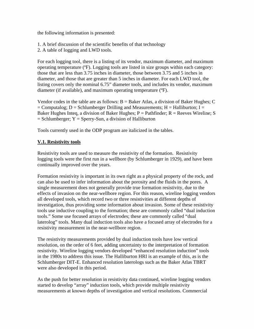
Logging tools that measure acoustic travel time have been around since the 1950s. These are twofold in purpose: to aid in porosity determination, and to provide acoustic velocity information to geophysicists.
The earliest acoustic tools recorded a compressional-wave travel time using one monopole transducer as a transmitter and one monopole transducer as a receiver. Subsequent tools used arrays of two transmitters and two receivers to compensate for irregularities in the borehole. Tools introduced in the early 1980s used more sophisticated arrays of monopole transducers, and waveform recording allowed processing of a shear-wave travel times (in relatively fast formations) as well as a compressional-wave travel times. Tools introduced in the late 1980s and early 1990s used arrays of dipole transducers to optimize the shear-wave recording and to allow recording a shear wave travel time in slower formations.
Geophysicists invariably prefer to get both compressional- and shear-wave data whenever possible, to help in their interpretation of seismic data. From a formation evaluation standpoint, the difference between compressional and shear data can provide information on the fluids in the pore space. IODP should use tools (or tool combinations) containing both monopole and dipole arrays, in order to record both shear- and compressional-wave data.
The 3.75 inch restriction should not limit the quality of sonic measurements. All of the vendors have monopole sonic tools less than 3.75 inches in diameter. These should be adequate for recording compressional-wave travel times in all but the slowest formations, and shear-wave travel times in faster formations. Schlumberger, Baker Atlas and Halliburton have tools with both monopole and dipole arrays, which permit a more direct recording of shear waves. Reeves Wireline is developing a slim dipole sonic tool for shear velocities to complement their slim monopole tool for compressional-wave velocities; availability is expected in May 2004.
LWD sonic tools are also available, using monopole arrays. The technology is essentially the same as wireline technology. The Sperry-Sun BAT tool uses two opposed monopole transmitters to give a pseudo-dipole, allowing shear wave recording in slower formations. Table of sonic tools
Tool Name Vend. Diam. Temp. Notes Tools under 3.75” diameter MSS Compact sonic sonde R 2.25 257 Monopole tool Under development
Compact dipole sonic sonde R 2.25 257 Dipole tool
SLIM Array sonic
SLIM array sonic tool S 2.50 300 Monopole tool
HFWS Hostile Full-wave sonic H 2.75 500 Monopole tool
DAR Digital acoustic array C 3.40 n.a. Monopole tool MAC Multipole array acoustilog B 3.63 400 Both monopole and dipole DSI Dipole sonic imager S 3.63 350 Both monopole and dipole Array sonic Array sonic tool S 3.63 350 Monopole tool FWST Full wave sonic H 3.63 350 Monopole tool LFDT Low frequency dipole tool H 3.63 350 Both monopole and dipole Wave sonic Cross dipole acoustic tool H 3.63 350 Both monopole and dipole LCS Long spaced compensated sonic R 3.74 302 Monopole tool CSS Compensated sonic sonde R 3.74 302 Monopole tool Tools 3.75” to 5” diameter XMAC Cross-multipole array
acoustilog B 3.88 400 Both monopole and dipole
XACT Cross-dipole acoustic tool H 4.75 302 Both monopole and dipole LWD sonic tools ISONIC IDEAL sonic while drilling D 7.50 300 Monopole APX Acoustic properties explorer I 6.75 302 Monopole CLSS Compensated long-spaced sonic P 6.75 302 Monopole BAT Bimodal acoustic tool Y 6.75 302 Monopole and pseudo-dipole Italicized tools are those used in ODP V.4. Neutron porosity tools
Neutron porosity tools use a source of high-energy neutrons to create a cloud of neutrons in the formation, and record the lower energy neutron flux at a detector or series of detectors. The flux measured at the detectors depends on reactions that reduce the energy of the neutrons such as collisions with other nuclei. Neutrons are slowed down most by collisions with hydrogen nuclei, and to a lesser extent by collisions with heavier nuclei. The neutron log response is interpreted as a “hydrogen index,” which is defined such that the response in a tank of pure water at 60 degrees F is 1. The hydrogen index is closely related to porosity in a water-filled formation.
Conventional compensated neutron tools use a chemical source (such as Am-Be or Pu-Be) for the neutrons and two
3
He neutron detectors at different spacings. Vendors spent a large amount of time and money in the 1970s and 1980s designing different detector shields and geometries to optimize the measurements, some preferring to detect thermal neutrons and others preferring to detect epithermal neutrons. In each case, the ratio of the count rates at the two detectors was converted to porosity units making a variety of assumptions.
In the early 1990s, Schlumberger introduced the Accelerator Porosity Sonde (APS),
which uses a pulsed source of neutrons rather than a continuous chemical source, and an array of 5 detectors. The source is a small accelerator, which slams deuterium into a tritium target to generate the neutrons. Four of the detectors are optimized for epithermal neutrons, and one for thermal neutrons. The tool provides a formation capture cross section as well as neutron porosity measurements comparable to (but different from) those of the conventional neutron tools.
Later in the 1990s, Schlumberger introduced an integrated package called the Platform Express, which incorporates bulk density, spectral gamma ray, and a neutron measurement into one small package. This neutron tool uses a chemical source and an array of GR detectors rather than the
3
He neutron detectors used by the other tools. Logs from this tool are also comparable to (but different from) those of the conventional neutron tools.
The 3.75 inch restriction should not limit the quality of the neutron measurements. All of the vendors provide conventional dual-spaced thermal neutron tools less than 3.75 inches in diameter. The Schlumberger APS is also under 3.75 inches in diameter.
LWD neutron tools are available from each LWD vendor. Although the tool geometries vary markedly, and some use GR or
6
Li detectors rather than 3
He neutron detectors, studies have shown the logs to be comparable to (but different from) those from wireline logs.
Table of neutron porosity tools
Tool Name Vend. Diam. Temp. Notes Tools under 3.75” diameter MDN Compact dual neutron sonde R 2.25 257 SLIM Slim-hole compensated
neutron S 2.50 300
CNL Compensated neutron log S 2.75 500 HDSN Dual spaced neutron H 2.75 500 CN Compensated neutron B 2.75 450 SLIM Xtreme
High-temperature slim-hole Compensated neutron
S 3.00 500
SWN Sidewall epithermal neutron B 3.00 400 Epithermal neutrons CNL Compensated neutron log S 3.38 400 APS Accelerator porosity sonde S 3.38 350 Non-chemical source CNT Compensated neutron H 3.38 375 CN Compensated neutron C 3.40 400 DSNII Dual spaced neutron II H 3.63 400 CN Compensated neutron B 3.63 400 DSEN Epithermal neutron H 3.63 400 Epithermal neutrons CNS Compensated neutron sonde R 3.74 302
Tools 3.75” to 5” diameter SNL Sidewall neutron tool H 4.00 350 Epithermal neutrons HGNS/PEX Highly integrated GR neutron S 4.63 260 Part of PEX triple combo LWD neutron tools ADN Azimuthal density neutron D 7.25 300 CCN Caliper-corrected neutron I 6.75 302 DNSCM Density neutron standoff
caliper P 6.75 302
CNF Compensated neutron porosity Y 6.75 302 Italicized tools are those used in ODP V.5. Temperature tools
Temperature logging tools perform the obvious service of measuring temperature as a function of depth in the wellbore. Continuous temperature measurement is a routine part of industry cased-hole logging, but not as common in open-hole operations. Typically one prefers to measure temperature on the way down, before the fluids in the wellbore are disturbed by the logging process.
All vendors have tools that can measure temperature. The 3.75 inch restriction should not limit the quality of the temperature measurements.
LWD temperature measurements, if available, will reflect the mud temperature during the drilling process and will not be reflective of formation temperatures.
Table of temperature tools
Tool Name Vend. Diam. Temp. Notes Tools under 3.75” diameter TLT Temperature H 1.44 375 TEMP Borehole temperature B 1.69 600 PTS Pressure temperature sonde R 1.69 302 MHT Borehole Temperature R 2.25 257 TEMP Borehole temperature B 3.38 400 AMS Auxiliary measurement sonde S 3.63 350 HRT Temperature logging H 3.63 400 Temperature Temperature C n.a. n.a. Part of production log
string
Italicized tools are those used in ODP V.6. Gamma ray spectroscopy tools
Gamma-ray spectroscopy tools provide quantitative measurements of potassium, thorium and uranium contents of the rock. In the oilfield environment these data are used to determine clay types, and occasionally as part of a geochemical analysis. In the scientific drilling environment, these data provide more basic information than can be interpreted from a simple gamma ray log.
Schlumberger, Halliburton and Baker Atlas all have natural gamma-ray spectroscopy tools less than 3.75 inches in diameter. Reeves have one at 3.74 inches, and a slimmer tool under development. The 3.75 inch restriction should not limit the quality of the gamma ray spectroscopy measurements.
Gamma ray spectroscopy is not currently available in LWD tools.
Table of gamma-ray spectroscopy tools
Tool Name Vend. Diam. Temp. Notes Tools under 3.75”
diameter
Under development Compact spectral GR R 2.25 257
HNGS Hostile natural GR H 2.75 500 NGS Natural gamma ray
spectrometry S 3.38 300
CSNG Spectral natural gamma ray H 3.63 400 SL Spectralog B 3.63 500 SGS Spectral gamma sonde R 3.74 302 HNGS Hostile NGS S 3.75 500 Tools 3.75” to 5” diameter NGS Natural gamma ray
spectrometry S 3.88 350
SGR Spectral gamma ray C 4.00 350 SGR Spectral gamma ray H 4.00 350
Italicized tools are those used in current ODP V.7. Caliper tools
Density tools typically provide a single-arm caliper measurement. This discussion covers only 4-arm calipers, which give borehole size information in two orthogonal directions. This information is useful for determining the direction of maximum horizontal stress in a vertical wellbore.
The 3.75 inch restriction should not limit the quality of the caliper measurements. Schlumberger, Halliburton, Reeves and Baker Atlas all have 4-arm caliper tools less than 3.75 inches in diameter.
Caliper measurements are not available while drilling. However, all LWD vendors offer a caliper computed from acoustic measurements, the density tool, and/or electrical measurements. Pathfinder’s “Density Neutron Standoff Caliper Multilink Tool” and Baker Hughes Inteq’s “Optimized Rotational Density” tool offer 3 acoustic calipers with 120 degrees of azimuthal separation.
Table of caliper tools
Tool Name Vend. Diam. Temp. Notes Tools under 3.75” diameter MTC Compact 2-arm caliper R 2.25 257 4-arm measurement when run in
conjunction with MPD HECT Hostile 4-arm caliper H 2.75 500 CAL Caliper log B 2.75 600 1, 2, 4 and 6 arm available BGT Borehole geometry tool S 3.38 350 FACT 4-arm caliper tool H 3.63 400 Tools 3.75” to 5.0” diameter TAC Two-arm caliper R 3.94 302 4-arm measurement when run in
conjunction with PDS Italicized tools are those used in ODP V.8. Check shots and vertical seismic profiling (VSP) tools
Check shot and vertical seismic profile data are used to tie seismic data to the wellbore. Vertical seismic profiling can also be used to generate near-wellbore seismic sections. The tools used for both purposes are similar. The basic concept is to shoot air or water guns as a seismic source, and record the seismic signal at numerous levels in the borehole. For check shots and basic VSPs, the guns are deployed over the side of the drillship. In an “offset VSP”, an additional boat is used to deploy guns at different distances and azimuths from the drillship.
At present, adequate tools are available under 3.75 inches in diameter.
LWD versions of this service do not exist at present. However, Baker Atlas offers a “seismic while drilling” service that uses the drillbit as a seismic source and an array of receivers in the sea.
Check shot/VSP tool table
Tool Name Vend. Diam. Temp. Notes Tools under 3.75” diameter SWST Slim well seismic tool S 1.69 350 SHR Slim-hole receiver B 1.69 392 6205XA Downhole receiver B 3.38 400 QSST Inline check-shot tool S 3.38 400 Runs with triple combo ASI Array seismic imager S 3.38 350 VSI Vertical seismic imager S 3.50 350 6222XA Downhole receiver B 3.63 392 WST Well seismic tool S 3.63 350 n.a. Downhole receivers H n.a. n.a. Tools 3.75” to 5” diameter SAT Seismic acquisition tool S 4.00 330 6204XB Downhole receiver B 4.15 392 CSI Combinable seismic imager S 4.63 350 Italicized tools are those used in ODP V.9. Borehole imaging tools
Borehole imaging tools provide images of the borehole wall. These are useful for looking at small-scale sedimentary structures and at natural fractures. There are two types of imaging tools: acoustic and electrical.
Acoustic imaging tools use a rotating transducer, sending acoustic energy to the borehole wall and recording its reflection from the wall. Both the reflected energy and the travel times are typically recorded in these tools. These tools provide an image that covers 100% of the wellbore, even in rough boreholes. Vertical and azimuthal resolution are limited by the frequency of the acoustic pulse that is used.
Electrical imaging tools use a multitude of detectors (either electrode “buttons” or induction coils) to obtain an image. Typically these detectors are mounted on arms that
extend from the tool. Button detectors require contact with the formation. Azimuthal coverage is a function of the number of arms and their size, and of borehole size. Vertical and azimuthal resolution are superior to those of the acoustic imaging tools.
Schlumberger, Baker Atlas, Reeves and Halliburton have borehole imaging technology. With the exception of the Schlumberger FMS, which is a predecessor to the current FMI and not widely available, all imaging tools under 3.75 inches in diameter are acoustic in nature. The3.75 inch hole restriction generally eliminates the possibility of obtaining electrical images. A 5.0 inch hole restriction would allow for the use of the existing Schlumberger and Halliburton electrical imaging tools. Reeves Wireline have a design for a slim microresistivity imager, but they have not as yet decided to pursue its development. They would consider a joint development effort over the next few years if asked.
Some resistivity tools (such as the Schlumberger ARI) also provide rough electrical images. LWD provides limited imaging capability as well, with tools such as the Schlumberger Drilling and Measurements RAB tool.
Borehole imaging tool table
Tool Name Vend. Diam. Temp. Notes Tools under 3.75” diameter BTT Borehole televiewer S 1.75 300 Acoustic images SAS Slim acoustic scanner R 2.13 158 Acoustic images
CBIL Circumferential Borehole Imaging B 3.38 400 Acoustic images
CAST Circumferential Acoustic Scanning H 3.38 350 Acoustic images
BTT Borehole televiewer S 3.38 300 Acoustic images UBI Ultrasonic borehole imager S 3.38 350 Acoustic images FMS Formation microscanner S 3.63 350 Electrical images AST Acoustic scanning tool R 3.74 302 Acoustic images Tools 3.75” to 5” diameter EMI Electrical micro-imaging tool H 5.00 350 Electrical images FMI Formation micro-imager S 5.00 350 Electrical images Tools over 5” diameter STAR Star imager B 5.70 350 Electrical and acoustic images LWD Tools
RAB Resistivity At Bit D 7.75 300 Limited imaging capability Italicized tools are those used in ODP V.10. Element analysis
Geochemists would like to have a complete elemental analysis available from a wireline logging tool. Unfortunately, the technology does not exist for this. The Schlumberger ECS is the only commercially available tool for element analysis. It measures a limited number of elements using spectroscopy of both naturally occurring gamma rays and gamma rays induced by interactions between neutrons and specific nuclei in the formation. The tool is substantially too large in diameter to meet the 3.75 inch restriction, although it would narrowly fit through drillpipe with a 5.0 inch restriction.
There are also tools that use specific element measurements to estimate fluid saturations in cased holes. Both the Schlumberger RST and the Baker Atlas MSI fall into this category. These tools also use neutrons to activate the formation, recording gamma-ray spectra that result from the activation, and interpreting those spectra in terms of specific element concentrations. Neither tool has been optimized for application in open-hole scientific boreholes, perhaps looking for different elements than in the cased-hole application. However, both tools can record the gamma-ray spectra, and these can be reprocessed to extract estimates of certain element concentrations. Research projects in conjunction with both vendors might make this technology useful, allowing element analysis with tools below the 3.75 inch restriction.
It is important to reiterate that no “element analysis” tool can provide a full range of element analysis; such analysis would have to be done on the cores.
Table of element analysis tools
Tool Name Vend. Diam. Temp. Notes Tools under 3.75” diameter RST Reservoir saturation tool S 2.50 300 Would require research to
apply
MSI Multiparameter spectroscopy B 3.50 270 Would require research to apply
GLT Geochemical logging tool S 3.63 300 No longer supported by vendor Tools 3.75” to 5” diameter ECS Element capture spectroscopy S 5.00 350
Italicized tools are those used in ODP V.11. Formation test tools for pressures, fluid sampling and permeability
Formation test tools are commonly used to measure formation pressure and formation permeability, and also for fluid sampling. They all work on a similar principle: the tool is stopped, a probe is pushed into the borehole wall, and a small drawdown test (5 to 20 cm
3
) is performed. The pressure is monitored throughout the test with a quartz gauge and a strain gauge. Permeability is typically inferred from the drawdown rate, and formation pressure is recorded directly from the quartz gauge. If fluid samples are desired, the tool can also be configured to collect them through the probe.
The earliest generation of formation testers could obtain a single sample. Later generations allowed for multiple samples. The most recent generation of tools, introduced in the 1990s, have the flexibility of obtaining many samples, pumping out the formation to eliminate mud filtrate before capturing samples, and monitoring the fluids during the entire sampling process including the pumpout. The most recent generation of tools includes the Schlumberger MDT, the Halliburton RDT, and the Baker-Atlas RCI.
The 3.75 inch restriction reduces the options to two for measuring pressures and permeabilities: the Reeves MFT and the Schlumberger slim-hole RFT. While neither has the flexibility of the most recent generation of tools, both can get important information on pressures and permeability. The Reeves MFT does not sample. The slim-hole RFT can take two samples per trip, with no ability to pump to eliminate mud filtrate from the sampling process.
A 5.0 inch restriction would open up the possibility of running the state-of-the art tools. The primary advantages of the larger tools are in the realm of sampling, allowing pumpout of mud filtrate and monitoring the fluids during the sampling process.
There are currently two LWD options for formation testing while drilling. Sperry-Sun is currently field-testing a tool that performs a 5 minute test sequence on a drillstring. A “start” command is sent to the tool through the mud, after which the tool sets a probe, performs a 10 cc drawdown followed by a buildup, and retracts the probe, monitoring pressure every second. Pathfinder has a tool that sets two packers and performs a drawdown followed by a buildup on the interval between them, monitoring pressure continuously through the process. Both of these tools require mud-pulse telemetry to start the process.
Table of formation test tools
Tool Name Vend. Diam. Temp. Notes
Tools under 3.75” diameter MFT Compact repeat formation tester R 2.75 257 No sampling SRFT Slim-hole Repeat formation tester S 3.63 400 Basic tool Tools 3.75” to 5” diameter RFS-D Repeat formation sampler R 4.72 302 Basic tool RCI Reservoir characterization inst. B 4.75 350 State-of-the-art tool SFT Formation tester H 4.75 350 Basic tool MDT Modular formation dynamic
tester S 5.00 350 State-of-the-art tool
RFT Repeat formation tester S 5.00 400 Basic tool RDT Reservoir Description tool H 5.00 350 State-of-the-art tool Tools over 5” diameter RFS-C Repeat formation sampler R 5.51 302 Basic tool FMT Formation multitester B 6.13 350 Basic tool LWD Tools LWD FT Formation Tester While Drilling Y 6.75 302 8.5” - 9.875” holes DFT Drilling Formation Tester P 6.75 257 8.5” – 10.75” holes These tools are not used in the ODP V.12. Nuclear magnetic resonance tools for permeability
The most exciting development in the openhole logging field of the late 1980s and the 1990s was the development of a new generation of commercial tools for nuclear magnetic resonance logging.
The original nuclear magnetic logging tool was introduced in the 1960s by Schlumberger. It used the earth’s magnetic field as a permanent magnet, perturbed this field using an array of coils, and monitored the signal sent back to the coils as protons in the pore space relaxed back to the steady state. Because the earth’s field is not very strong, the signal-to-noise ratio was very low, and the tool was rarely used.
In the late 1980s, a company called Numar (now a division of Halliburton) introduced a tool that used a powerful magnet to generate the primary field. The improved signal-to-noise ratio made the technology more practical, and the technology rapidly developed. Schlumberger also introduced a tool that used a powerful magnet to generate the primary field, with a geometry quite different from that employed by Numar.
The relaxation of protons in the pore space is related to their distance from the pore
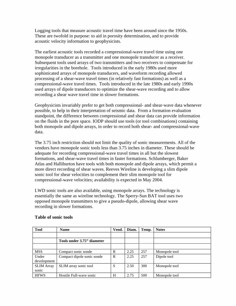
walls (among other factors). The new NMR technology uses this to provide an estimate of the pore size distribution, from which one can infer the permeability. It also enables the user to distinguish between porosity through which fluids can flow (called “free-fluid porosity”) from porosity through which fluids cannot flow. These are extremely important measurements in the oilfield. Both permeability and free-fluid porosity are of potential importance in the IODP as well, especially in geothermal systems and in other environments where fluid flow is of interest.
Current technology is too large for the 3.75 inch restriction. Halliburton has a tool that will fit through a 5.0 inch restriction.
Vendors are working on LWD versions of this tool, with Sperry-Sun and Schlumberger Drilling and Measurements already having commercial tools.
Table of magnetic resonance tools
Tool Name Vend. Diam. Temp. Notes Tools under 3.75” diameter None Tools 3.75” to 5” diameter MRIL-slim Magnetic resonance imaging log H 4.88 350 Tools over 5” diameter CMR+ Combinable magnetic resonance S 5.30 350 MRIL Magnetic resonance imaging log B, H 6.00 350 LWD Magnetic Resonance
tools
ProVision ProVision D 6.75 300 Hole sizes 8.375 to 10.625” MRIL-WD MRIL while drilling Y 6.75 302 Hole sizes 8.5 to 10.625” These tools are not used in the ODP V.13. Magnetic susceptibility logging tools
There are no commercially available logging tools of this type. Schlumberger used to have the GHMT, but it is no longer supported. The best way for IODP to record this type of data might be to purchase two tools and any existing spare parts from Schlumberger, with the intention of IODP staff being responsible for their maintenance and application.
V.14. VSP tools
Please see section V.8. VSP tools are included with check-shot tools.
VI. Integrated logging packages
Several years ago, Schlumberger introduced the “platform express” triple combo with several features that would be ideal for IODP logging. New technology allows density, neutron, GR and resistivity logging at about twice the logging speed as the conventional HLDT-AIT-IPLT-GR triple combo. Rig-up and rig-down time are substantially reduced because the tool is about one third the length of the conventional triple combo. Also, through clever use of accelerometers and other integrated sensors, the tool provides real-time depth-matched borehole-corrected data, which are of significantly better quality than a conventional triple combo in an environment with substantial heave (such as a drillship). Unfortunately, the platform express combo is 4.63 inches in diameter, so its use for IODP would require a larger drillpipe than that used by the ODP.
VII. Drillpipe Size
IODP could better achieve the CDC goals if they were to consider the use of a larger drillpipe. The following table lists the specific tools, providing technology not presently available below 3.75” diameter, that could be added as a function of increasing allowable tool OD. It is clear from this table that a 5.0 inch restriction would allow the vast majority of tools to pass. All wireline logging technologies of interest to IODP can be obtained through a 5.0 inch restriction.
Size Tool added Vend. Comments/Advantages 4.63 PEX S Better-quality triple combo data 4.75 RCI B State-of-the-art formation tester, including sampling 4.88 MRIL-slim H Magnetic resonance 5.00 EMI H Electrical imaging 5.00 FMI S Electrical imaging 5.00 ECS S Element analysis 5.00 MDT S State-of-the-art formation tester, including sampling 5.00 RDT H State-of-the-art formation tester, including sampling 5.30 CMR Plus S Magnetic resonance 5.70 Star B Electrical and acoustic imaging 6.00 MRIL H,B Magnetic resonance
VIII. Summary and Conclusions
Conventional wireline measurements provide the best way to meet most of the CDC goals for data collection in the scientific boreholes to be drilled by IODP. Riserless drilling provides an element of challenge, in that the tools need to be conveyed to the hole through drillpipe. For the ODP, this has placed a 3.75 inch diameter restriction on the logging tools. Many of the required measurements can be obtained with this restriction. However, IODP could better achieve the CDC goals if they were to consider the use of a larger drillpipe with a 5.0 inch diameter restriction. The following table lists the types of logs that can be obtained from each of these vendors. The codes are as follows: “A” indicates that a tool under 3.75” diameter is currently available (or under development). “B” indicates that a tool between 3.75 and 5” is currently available. “O” indicates that an “old” technology tool is currently available, but no longer supported by the vendor. A number indicates the diameter of a tool over 5.0”.
Tool type B C H R S State-of-the-art array resistivity A A A A State-of-the-art lithology density A B A A A State-of-the-art shear and compressional sonic A A A A State-of-the-art neutron porosity logs A A A A A Sourceless neutron porosity log A Temperature logs A A A A A Gamma-ray spectroscopy A B A A A Four-arm caliper A A A A Check shot/VSP A B A A Acoustic borehole imaging A A A A Electrical borehole imaging O State-of-the-art electrical borehole imaging 5.70 B B Element analysis B Basic formation tester A A State-of-the-art formation tester for sampling B B B Nuclear magnetic resonance logging 6.00 B 5.30 Magnetic susceptibility logging O Integrated platform for improved triple combo B
LWD options exist for some of these measurements. LWD vendors evaluated were Schlumberger Drilling and Measurements (D), Baker Hughes Inteq (I), Pathfinder (P) and Sperry Sun (Y). Sperry Sun and Schlumberger have the most complete suites, followed closely by Baker Hughes Inteq and Pathfinder.
The following table lists the types of LWD services that can be obtained from each vendor. The codes are as follows: “A” indicates that a tool is available “L” indicates that a tool with limited functionality is available.
Tool type D I P Y Basic resistivity (2 measurements) A A A A Array resistivity A A A Bulk density A A A A Shear and compressional sonic (fast formations) A A A A Shear sonic in slow formations A Neutron porosity A A A A Temperature Electrical borehole imaging L Basic formation tester L L Nuclear magnetic resonance logging A A Given its limited abilities, and the need to drill a separate hole, LWD operations might not be considered for all legs of the IODP. Fit-for-purpose LWD could be contracted for each leg in which it is needed.