IRICEN JOURNAL OF CIVIL ENGINEERING IRICEN JOURNAL OF CIVIL ENGINEERING www.iricen.indianrailways.gov.in VOLUME 7, No. 1 & 2 MARCH & JUNE 2014 Indian Railways Institute of Civil Engineering, Pune - 411001
Transcript
IRICEN JOURNAL OF CIVIL ENGINEERING
IRICEN JOURNAL OF CIVIL ENGINEERING
www.iricen.indianrailways.gov.inVOLUME 7, No. 1 & 2 MARCH & JUNE 2014
Indian Railways Institute of Civil Engineering, Pune - 411001
IMPORTANT RECOMMENDATIONS OF PCE SEMINAR HELD ON
th20 & 21 MARCH 2014
AT IRICEN/PUNE.
st
1. Correction slip be issued early for increasing the Track center to 7.8 m as recommended in TSC.
2. Railways shall send proposal to Railway Board for converting regular nature work charged post to revenue post.
3. Matching surrender shall not be insisted upon for creation of post for new assets.
4. No goods train shall be pushed in corridor blocks and blocks agreed as per joint programme signed by COM & PCE without personal consent of PCE.
5. A special allowance of Rs 2000/- be granted to Gate Man.
1. A committee of CE/Plg/SR, CE/Works /SCR & SPW/IRICEN is formed to look into various issues related with the policy of Zonal contracts in Railways.
2. For issues related with GCC, a committee of CPDE/NWR & CPDE/NFR & SPW/IRICEN is constituted.
IMPORTANT RECOMMENDATIONS OF CHIEF ENGINEER / PLANNING SEMINAR HELD
thON 10 & 11 APRIL 2014
AT IRICEN / PUNE.
th
Dear Readers,
IRICEN is alma mater for all IRSE officers and I am now privileged to
be a member of IRICEN faculty since March 2014. It is my pleasure to
interact with the vast fraternity of Railway engineers through this Journal.
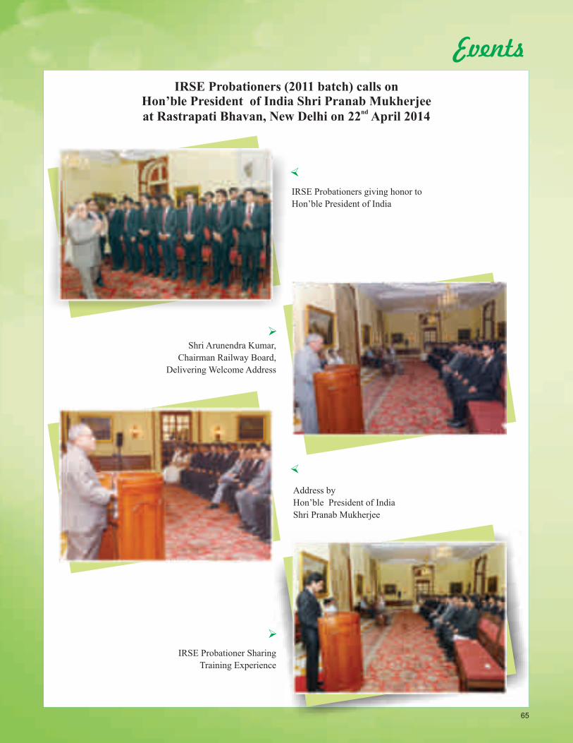
I am happy to inform that IRSE probationers (2011 batch) had the
honour to call on the Hon’ble President of India on 22.04.14 at Rashtrapati
Bhawan, New Delhi. It is an honour and memorable session for engineering
officers at the beginning of their career in prestigious railway services to
interact with the Hon’ble President of India. ThiThis interaction will motivate
them throughout their career.
Indian Railways is considered backbone of Indian Economic
Development. With the renewed emphasis on infrastructure development,
Railways shall play a vital role, with greater emphasis on fast track
development of rail infrastructure.
As you all known that as Engineering plays a significant and important
role in infrastructure building, we have to energize ourselves to successfully
undertake the challenges ahead. Our endeavour should be to simplify
processes with an objective to minimize the time taken in various
stages/activities of decision making and execution of works.
Safety in all aspects of Railway working be it operations or
construction, is of paramount importance and therefore can never be over
emphasized. The papers relating to safety in building construction and
dismantling of ROB bring often the trivialized and glossed over issues to the
fore. One of the papers included in this edition relating to land acquisition for
infrastructure projects highlights the importance of the issue, along with
various social and environmental aspects.
I am sure that the readers of this Journal would find value in the various
papers/articles included in this Journal. I request all the readers to send their
suggestions and send their articles/paper etc for inclusion in future issues for
future editions of this Journal.
( Vishwesh Chaubey )
Director
I n d e x01I) Railway News
II) Other News
IV) Technical Papers
V) Literature Digest
VI) Events
Guidelines to contributorsArticles on the Railway Civil Engineering are welcome from the authors. The authors who are willing to contribute articles in the IRICEN Journal of Civil Engineering are requested to please go through the following guidelines :
1. The paper may be a review of conventional technology, possibilities of improvement in the technology or any other item which may be of interest to the readers. The paper should be reasonably detailed so that it could help the reader to understand the topic. The paper may contain analysis, design, construction, maintenance of railway civil engineering assets. The paper should be concise.
2. The journal is likely to be printed in a paper of size 215 mm X 280 mm. While sending the articles the author should write in 2 columns. Sketches, tables and figures should be accommodated in a 2 column set up only.
3. Author should send the original printout of photograph along with the digital copy of the photograph.
4. Soft copy as well as hard copy of article must be invariably sent to the editors of concerned subject.
5. Only selected articles will be included in the IRICEN Journal of Civil Engineering.
Shri C. S. SharmaSr. Professor Track - IIExecutive Editor
EDITORIAL BOARD
Shri Vishwesh ChaubeyDirector/IRICENChairman
Shri R. P. SaxenaSr. Professor / Engg.Co - Chairman
The papers & articles express the opinions of the authors, and do not necessarily reflect the views of IRICEN editorial panel. The institute is not responsible for the statements or opinions expressed in its publication.
EDITING TEAM
TRACK
WORKS
BRIDGES
Shri N. C. ShardaSr. Professor Track - I
Professor Track
Professor - Track Machine
Professor - Track I
Lecturer - Works
Lecturer - Track - I
Sr. Professor Works
Sr. Professor Projects
Associate Professor/Est.
Associate Professor
Sr. Professor Bridge - II
Sr. Professor Bridge - I
Professor Bridge
Shri Nilmani
Shri M. B. Dekate
Shri N. K. Mishra
Shri N. R. Kale
Shri J. M. Patekari
Shri S. K. Garg
Shri Surendra Kr. Bansal
Shri Neeraj Khare
Shri Shyam Khoche
Shri R. C. Boolchandani
Shri Vineet Gupta
Shri Sharad Kumar Agarwal
Associate
1. Provisions Regarding Deflection/Camber in Various National and International
Codes for Rail & Road Bridges.
By: Ajay Goyal, CE/C/N/CR
2. Safety in Building Construction.
By :
3. Land Acquisition, Social and Environmental Issues in Infrastructure Projects.
By :
4. Dismantling of ROB Using Controlled Blasting Method.
By :
B. K. Tirkey, CE/C.R
Sharad Kumar Jain, CE/C/Planning/SWR
K. Renukananda Shetty, AXEN/C/SWR, V.S.Singh, AXEN/C/ECR.,
Daya Ram AXEN/C/NR
04
Suggestion for improvement of are welcome from the members. Suggestion may be sent to [email protected]
IRICEN JOURNAL OF CIVIL ENGINEERING
III) New Products
09
21
33
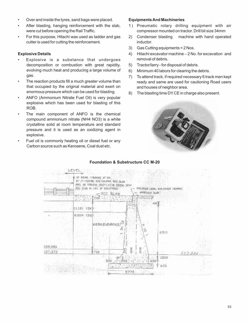
52
57
06
65
1
Work on Udhampur-Katra Rail Line in Concluding
Stages
Work on the 25-km –long railway track between
Udhampur and Katra sections after a series of delay is
finally in the concluding stage. The Katra line was
expected to be operational by the and of August last
year as work was going on full throttle. The date was
further extended to October last year. Laying work on 18
km long track between Kajikund and Banihal in Jammu
and Kashmir is already complete. While DMUs were
already plying from Banihal to Baramula, and also 42
kms long track between Fazlika and Abohar had been
Laid.
Ref:- The Masterbuilder,
Mar. 2014, Vol-16, Pg -30.
Delhi Metro to Assist Lahore Metro Rail
Pakistan’s Punjab province desires to explore the
possibilities of cooperation with DMRC in setting up a
metro rail system in Lahore. Shortly after his arrival, the
Punjab province chief minister met DMRC to learn from
their experience in running metro rail in Delhi. His
government is expected to invite bids from the global
construction firms for construction of metro network in
Lahore.
Ref: NBM&CW, Jan. 2014, Pg-30.
India Offers Cheapest Metro Projects
According to the Urban Development Secretary,Sudhir
Krishna, in view of the easily available manpower at
reasonable cost, India offers the cheapest metro
projects in the world. He made this claim during his
address at an event organised by the CII and added
that the next highest is something that is 20% more but
generally it is 40% more than Indian metro projects.
While India is not manufacturing all the components,
the key lies in the country’s large population which
allows us to deploy more people in a project. Due to
sufficient availability of the manpower, the government
can break the project into different components and
then bid to get the best possible competitors who are
experts in fields, whether it is the signalling system or
the rolling stock or in regard to construction of the civil
structure. Urbanisation has gathered pace in India and
the current trend was that small-and mid-sized cities
were growing at a faster pace. Keeping this in mind, the
government has fast tracked the work on three
Regional Rapid Transit Systems (RRTS) corridors
connecting Panipat,Meerut and Alwar with the
national capital.
Ref: NBM&CW, Jan. 2014, Pg-30.
FDI in Railways
Introduction of FDI policy in Railways could be delayed.
Scope and coverage of the policy and the preferred
route for bringing in the foreign investment needed fine
tuning. Accordingly to the Department of Industrial
Policy & Promotion (DIPP), the railways is yet to provide
some clarifications on routes through which it wants the
investment to come in and areas which the railways
would like to open up for investors. DIPP,which
formulates foreign investment policies has stated that
investors in the FDI policy could be allowed to hold
100% stake in the SPVs meant for construction of ports,
connectivity projects and railway lines connecting
mines. Railways stance is that it wants to go beyond FDI
in connectivity projects, to areas where it has PPP as the
Railways is targeting to attract Rs 6000 crore through
the PPP route this year.
Ref: NBM&CW, Jan. 2014, Pg-32.
Marathon Runs Europe’s L ongest Freight Train
French national railways (SNCF) in cooperation with
French Rail Network (RFF) and intermodal operator
Kombiverkehr operated a 1500m-long freight train on
January 18 between Sibelin yard near Lyon and Nimes
as part of Europe’s marathon project to operate longer
freight train.
This is the first test operation of a 1500m-long freigt train
in Europe and was achieved by reforming three of
2
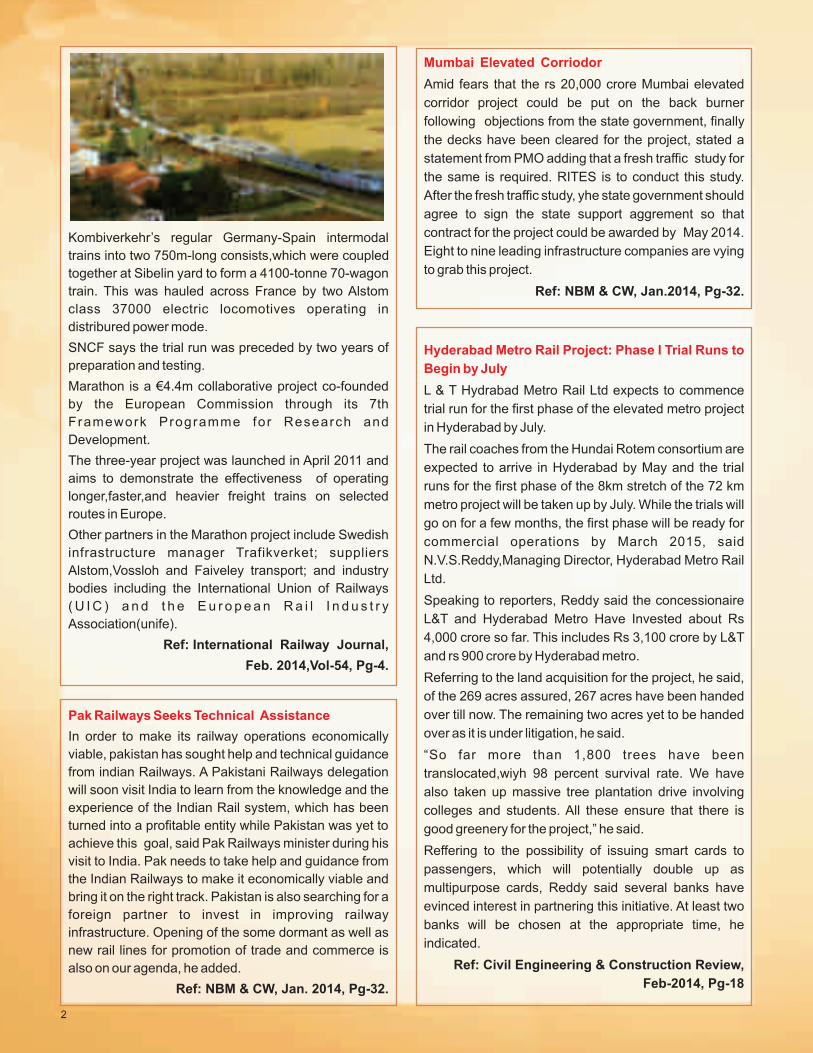
Kombiverkehr’s regular Germany-Spain intermodal
trains into two 750m-long consists,which were coupled
together at Sibelin yard to form a 4100-tonne 70-wagon
train. This was hauled across France by two Alstom
class 37000 electric locomotives operating in
distribured power mode.
SNCF says the trial run was preceded by two years of
preparation and testing.
Marathon is a €4.4m collaborative project co-founded
by the European Commission through its 7th
Framework Programme for Research and
Development.
The three-year project was launched in April 2011 and
aims to demonstrate the effectiveness of operating
longer,faster,and heavier freight trains on selected
routes in Europe.
Other partners in the Marathon project include Swedish
infrastructure manager Trafikverket; suppliers
Alstom,Vossloh and Faiveley transport; and industry
bodies including the International Union of Railways
( U I C ) a n d t h e E u r o p e a n R a i l I n d u s t r y
Association(unife).
Ref: International Railway Journal,
Feb. 2014,Vol-54, Pg-4.
Pak Railways Seeks Technical Assistance
In order to make its railway operations economically
viable, pakistan has sought help and technical guidance
from indian Railways. A Pakistani Railways delegation
will soon visit India to learn from the knowledge and the
experience of the Indian Rail system, which has been
turned into a profitable entity while Pakistan was yet to
achieve this goal, said Pak Railways minister during his
visit to India. Pak needs to take help and guidance from
the Indian Railways to make it economically viable and
bring it on the right track. Pakistan is also searching for a
foreign partner to invest in improving railway
infrastructure. Opening of the some dormant as well as
new rail lines for promotion of trade and commerce is
also on our agenda, he added.
Ref: NBM & CW, Jan. 2014, Pg-32.
Mumbai Elevated Corriodor
Amid fears that the rs 20,000 crore Mumbai elevated
corridor project could be put on the back burner
following objections from the state government, finally
the decks have been cleared for the project, stated a
statement from PMO adding that a fresh traffic study for
the same is required. RITES is to conduct this study.
After the fresh traffic study, yhe state government should
agree to sign the state support aggrement so that
contract for the project could be awarded by May 2014.
Eight to nine leading infrastructure companies are vying
to grab this project.
Ref: NBM & CW, Jan.2014, Pg-32.
Hyderabad Metro Rail Project: Phase I Trial Runs to
Begin by July
L & T Hydrabad Metro Rail Ltd expects to commence
trial run for the first phase of the elevated metro project
in Hyderabad by July.
The rail coaches from the Hundai Rotem consortium are
expected to arrive in Hyderabad by May and the trial
runs for the first phase of the 8km stretch of the 72 km
metro project will be taken up by July. While the trials will
go on for a few months, the first phase will be ready for
commercial operations by March 2015, said
N.V.S.Reddy,Managing Director, Hyderabad Metro Rail
Ltd.
Speaking to reporters, Reddy said the concessionaire
L&T and Hyderabad Metro Have Invested about Rs
4,000 crore so far. This includes Rs 3,100 crore by L&T
and rs 900 crore by Hyderabad metro.
Referring to the land acquisition for the project, he said,
of the 269 acres assured, 267 acres have been handed
over till now. The remaining two acres yet to be handed
over as it is under litigation, he said.
“So far more than 1,800 trees have been
translocated,wiyh 98 percent survival rate. We have
also taken up massive tree plantation drive involving
colleges and students. All these ensure that there is
good greenery for the project,” he said.
Reffering to the possibility of issuing smart cards to
passengers, which will potentially double up as
multipurpose cards, Reddy said several banks have
evinced interest in partnering this initiative. At least two
banks will be chosen at the appropriate time, he
indicated.
Ref: Civil Engineering & Construction Review,
Feb-2014, Pg-18
2
3
India, ADB Sign US$ 130 Million Loan Agreement to
Improve Rail Infrastructure
The Government of India and Asian Development Bank
(ADB) signed US$130 million loan agreement to help
India improve rail services along some of its busiest and
most critical freight and passenger transport routes. The
second tranche loan is part of the US$500 million
Railway Sector investment program approved by ADB
in 2011, and will finance track components for 840
kilometers of additional tracks along existing railway
lines.
The signatories to the loan were Mr. Nilaya Mitash, Joint
secretary(Multi lateral Institutions), Department of
Economic affairs, ministry of Finance on behalf of the
Government of India, and Ms. M. Teresa Kho, Country
Director(INRM), on behalf of ADB. The project
agreement was signed by Mr. Satish Agnihotri, CMD,
RVNL.
Ref: The Masterbuilder, Mar-2014, pg-30
India Looks to Foreign Investors to Fund Rail
Projects.
During the announcement of an interim budget of Rs
643bn (US$ 10.26bn) for Indian Railways for 2014-15,
India’s railway minister Mr. Mallikarjun Kharge outlined
plans to allow Foreign Direct Investment(FDI) to fund
infrastructure projects,
Kharge told the Lok Sabha, India’s lower house of
parliament, that Indian Railways’ proposal to obtain
foreign investment to fund high speed and semi high
speed(160-200km/h) rail projects is likely to be
approved shortly by the cabinet.
Kharge reiterated that concrete progress on the
Mumbai-Ahmedabad high-speed project is likely after
the completion of a Jica-sponsored survey. Semi-high-
speed services are planned on the Delhi-Agra and
Delhi-Chandigarh lines. “Our plans are to make one of
these routes operational by the year end,” IR’s
Chairman Mr Arunendra Kumar said later.
The railway minister emphasised the need to continue
reforms initiated by the ruling coalition. He said the Rail
Tariff Authority (RTA) would shortly become operational.
He also announced plans to run 17 premier trains using
a yield management pricing model akin to that used by
airlines and introduce 72 new train services.
IR’s financial performance is a continuing cause for
concern. Its operating ratio climbed from 87.8% to
90.8% for the current financial year. IR has suffered a
substancial reduction in passenger revenue, while fuel
costs have spiralled.
As a result of shortfall in earnings, the ministry’s planned
outlay for the current financial year has been cut by
almost Rs40bn from Rs633bn to Rs593bn.
A new government will assume office in India in May
following national elections, when a full railway budget
will be presented.
Ref: International Railway Journal,
Mar 2014,Vol-54,pg-4
JR East’s First Battery EMU Enters Service this
Month
He first battery emu for JR East, which was delivered in
January, will enter service in march enabling through
operation on the partly-electrified line between
Utsunomiya and Karasuyama.
The series EV-E301 train will run as an emu on the
11.7km section from Utsunomiya to Hoshakuji which is
electrified at 1.5kVdc enabling the batteries to be
charged. The train will then switch to battery operation
for the remaining 20.4km non-electrified section to
Karasuyama. A short overhead catenary feeder section
has been installed at Karasuyama station for battery
charging.
The 100km/h train consists of two cars, each powered
by two 95KW traction motors and fitted with a 600V
95kWh lithium ion battery. The train, which has a
lightweight stainless-steel car body, was built by Japan
Transport Engineering Company, formerly Tokyu Car
Corporation, and now an affiliate of JR East, with Hitachi
supplying traction equipment and GS Yuasa Batteries.
Ref: International Railway Journal,
Mar 2014, Vol-54, pg-7
3
4
Train Running Test Using a Superconducting
Feeding Wire
On 24 July, 2013, Railway Technical Research Institute
(RTRI) published the running test of a train by a
superconducting cable for news media.
A feeding wire, which sends electricity to vehicles from a
substation, has an electrical resistance at present. If a
superconducting material free from this resistance can
be used for the transmission of electric power, it is
expected to have merits that the power obtained in
regenerative brake can be sent to the train at a distance
without any loss of power. In addition, it would also
reduce the number of substations by preventing
voltage drop.
In 2010, a prototype superconducting cable of 5m length
8 kA-class was manufactured and the evaluation of
performance was carried out. Compactness was
achieved by supplying a circulating refrigerant (super
cooled liquid nitrogen) necessary to keep the
superconducting state in one cable.
In FY 2012, the prototype superconducting cable of 31m
length 5 kA-class was manufactured. Driving tests using
this cable have started on the test line at the premises of
the Institute in June 2013. the running test of a train
using superconducting cable is the first in the world.
RTRI have planned the test using further long length
superconducting cable of 310m, by around the autumn
of 2013, and aim to complete the system suitable for
introduction on a commercial line.
Ref. : Japanese Railway Engineering,
January 2014, No.182, Pg-9
Vertical Vibration Control of Vehicles – Air Spring
Car’s First System
Railway Technical Research Institute (RTRI) and
Hitachi Automotive System Ltd. have newly developed
an up and down control system for an air spring vehicle.
This is a proven system for the coil spring, but there is no
precedent for air spring in the world.
This system was introduced into the cruise train.
“SEVEN STARS IN KYUSHU” of JR Kyushu, which
started operation in October,2013 and is quite useful in
vibration suppression. In the system, vertical motion
damper with variable damping function is installed on
two places on each truck in parallel with the secondary
spring (air spring) supporting a vehicle body. Expansion
of the damper is controlled in accordance with the
magnitude of the shaking detected by the acceleration
sensors provided, thus vibrations are reduced.
In “SEVEN STARTS”, the same system was equipped in
all seven passenger cars. Thus, compared with the air
spring vehicles existing, the peak value which indicates
the strength of vibration “vibration acceleration power
spectral density(PSD)”, was reduced significantly by
feature of maintenance strategies all over the world for
more than 30 years. The influence of this technology on
the durability of the track geometry following
construction and maintenance operation has been the
object of various studies again and again. In this
instance, Union Pacific Railroad (UP) measured the
behavior of a concrete tie track on a high-capacity line
under various conditions.
Ref. : Today, Year 41 Issue 122, Page:03
expected to complete by Dec 2016.
Ref: Tunnels and Tunneling, Jan. 2014, Pg-10
1. It was recommended that PCEs and CAOs should also be included in the mailing list of Stores Directorate.
2. RDSO is regularly upgrading the drawings, specifications and latest amendments related to track
procurement, if particular drawing is not available a reference can be made to RDSO.
3. For track procurement existing provision of performance guarantee (PG) should continue. For pooled PG,
Board may please issue guidelines.
4. Policy for trial items and comprehensive policy for dealing unsolicited offers may be issued by Railway
Board.
5. RDSO should work out better method for production of sleepers with tight tolerance (T-2 496 CH-4)
6. Adopting limited tender for track items where Board approval is must was recommended. Board may issue
instructions.
7. Tenderers not agreeing with the railway terms and conditions, should not be able to quote rates.
8. Weight should be made as a part of P.way materials description.
9. Variation upto 30% recommended without finance concurrence.
10. List of vendor needs to be modified such that a particular vendor is approved for all the components, which
are used as a set in order to streamline the procurement.
11. TC limit of SAG officers for track procurement be enhanced from existing 2 to 15 crores to 5-20 crores.
12. For trial items where no LPR is available for arriving on Reasonability of rates, CE/TP be authorized to
sanction rate analysis upto 20 lakhs based on WPI available for input material as per market survey certified
by Dy.CE/TP.
13. Limit of purchase order for supply of P.way material without constitution of TC by Dy.CE/TP on the basis of
rate reasonability certified by XEN/TP be enhanced from existing 5 lakh to 20 lakhs.
14. Force majeure clause should be introduced in IRS conditions.
15. Power to grant extention without LD with PVC & without denial clause upto 25% of total completion period
for the supplied quantity be delegated as per SOP.
IMPORTANT RECOMMENDATIONS OF CHIEF ENGINEER / TRACK PROCUREMENT'S th th
SEMINAR HELD ON 8 & 9 MAY, 2014 AT IRICEN / PUNE.
6
JLG Launches World’s Tallest Telescopic Boom
JLG Industries launched its 1850SJ Ultra boom, world’s
tallest telescopic boom with nearly three million cubic
feet of reachable space. With a working height over 185
feet ,this is the second boom introduced within the past
year to reach 180 feet or above. The 1850SJ includes a
telescopic jib that extends and retracts to provide
additional reach,up-and-over capability and the ability to
telescope into and around structures in a variety of
applications, including steel erection; energy-related
construction such as petrochemical ,power generation
and wind plants; stadium,convention center and theatre
construction; and entertainment and studio related
applications.
In addition, an exclusive updated platform LCD display
provides even more information to optimize service and
operator productivity.
Ref: The Masterbuilder,March-2015,Vol.16, Pg-20
ON TRACK - ENSCO Inc.
ENSCO’s first autonomous track inspection product
was the vehicle/Track Interaction (V/TI) monitor, which
has been available for about 10 years and is being used
by Class Is, Amtrak, and several other freight and
passenger railroads around the world. It’s designed to
monitor track conditions. It looks for conditions such as
poor surface geometry, poor support conditions and
impacts at the wheel-rail interface.
Recently, the company introduced the Autonomous
Track Geometry measurement system (ATGMS), an
unmanned real-time system designed to measure and
report track geometry exceptions, including gauge,
cross level , alignment and surface. The big advantage
of autonomous track geometry is that it no longer needs
a dedicated inspection vehicle with staff to operate it. If
it’s installed in a revenue train, it can test continuously
and get in considerably more testing on an annual basis.
In September, ENSCO introduced an upgrade to its
RailScan Lite Hi-Rail System, a non-contact sensor that
mounts on a hi-rail vehicle and connects to a laptop
computer to help inspectors look for deviations during
track inspections. The model that’s been on the market
measures two key geometry parameters: gauge and
cross level. The product upgrade performs full track
geometry measurements.
Ref.: Progressive Railroading,
Issue : December 2013, Pg-44.
ON TRACK - Plasser American Corp.
Plasser offers a full spectrum of track inspection
technology. Video monitoring is one of the latest trends
to emerge.
Recently, Plasser worked with a large urban transit
agency on a track inspection research project funded by
the Federal Transit Administration (FTA). The agency’s
track inspection car already was equipped with
Plasser’s track component video system that provided a
right of way, rail and gauge-side view of the track area.
The research project took that view a step further by
providing a field side view of the running rails and the
power rails ( or third rail) to complete the spectrum of
measurement and visual inspection of track
components.
The enhanced video monitoring function adds to
Plasser’s track recording and measuring systems to
assist inspectors in analyzing track geometry and other
data related to the rail profile, such as wear of the
running edge, rail inclination and rail surface faults.
Instead of having to walk the track and be in danger of
being hit by a train, the task of track walking can be
performed in the office. This provides a combined
review of track measurements and track video data.
Ref.: Progressive Railroading,
Issue : December, 2013, Pg-52.
7
Tata Steel- Europe's Second Largest Steelmaker
Tata Steel, Europe’s second largest steelmaker announced the launch of a new state of the art facility which will produce train track capable of lasting upto three times longer than standard rail.
The commissioning of the new heat treatment plant at Tata Steel’s Hayange plant, in the Lorraine region of France, means the company will be able to supply long lengths of super hardened rail that they say is heat treated and stress free. These rails of upto 108 meters in length will allow rail operators to enhance performance and reduce costs associated with more frequent worn rail replacement.
Heat treated rail can last upto three times longer than
standard rail when used in high wear conditions such as heavy traffic, high axle loads or tight curves designed to cope with heavier axle loads, as well as the traffic on metro systems, where heat treated rails need to have exceptional technical performance in demanding traffic conditions.
Tata Steels’ heat treated rail is produced using a unique patented process that ensures it has exceptional wear resistance. The rail moves through an induction furnace which uses an electromagnetic field to heat the steel to 9500C. The rail is then rapidly cooled using compressed air.
Ref. Permanent Way Institution Journal Issue : January,2014 Vol.132-part-1, Pg-33.
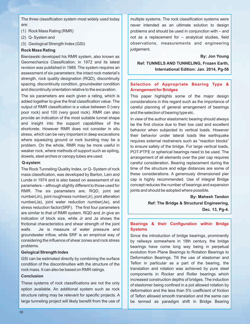
High Efficiency “Rubber Head” the Most Efficient tool for Consolidating Concrete Without Damaging
Epoxy Coated Rebar
Perfect Consolidation
Oztec's patented "RubberHead" with its large number of openings allows the wet concrete to cool the inner shell and acts like "suction cups", keeping the concrete in constant contact with the entire length of the vibrator head, sending strong shock waves into the mass. The Oztec RubberHead is available in a range of shapes and sizes for any application.
n Will outperform any other type of vibrator... round, square, hi-cycle, etc... Any Type!
n Will protect epoxy coated rebar and expensive forms.
n Is outstanding in low slump (to "0" slump) concrete.
n Essential in large pours of very stiff concrete.
n Makes concrete denser with less voids to patch.
n Vibrates @ 12,000vpm, never drops below 10,500 vpm when lowered deep into low slump concrete.
n Is an absolute must for Architectural concrete where cosmetic surfaces are essential.
n Can be used with Oztec electric or gas powered units.
Oztec's uniform, high efficiency action delivers vibration
along the entire length of the vibrator head. This assures
better consolidated concrete and is job proven to be
more efficient than any other vibrator head on the
market.
When a smooth vibrator head (round, square or any other shape) is lowered into a relatively stiff concrete batch, the front or nose of the vibrator drills a hole. It pushes away concrete faster than it can return. Result, shock waves produced mostly from the vibrator's front end.
RubberHead Standard
vibrator head
For details, refer www.oztec.com Ref: Concrete International, vol-36, Feb-2014, Pg-15
8
Concrete Reinforcement Products
Quality Engineered Products
Proven Performance
Trusted Experts
Worldwide Code Compliance
1. Terminator
Alternative to hooked rebar anchorage
2. Quick Wedge
Ideal for quick retrofit
3. Cadweld
Premiere mechanical splicing system
4. Interlock
Ideal for precast structures
5. Taper Threaded Couplers
Slimmest coupler on the market
6. Speed Sleeve
For compression situations
7. Form Saver
Ideal for segmental pour
8. Lock
Ideal for in-situ splices
Ref: Concrete International, vol-36,
Feb-2014, Pg-24.
Hilti HIT-HY 200 Adhesive Anchor System
Hilti introduced its HIT-HY Adhesive Anchor System. It
can be installed with the traditional blow-brush-blow
method using compressed air and a wire brush to clean
the drill hole. HIT-HY 200 requires two blows of
compressed air, two brushes, and two more blows of
compressed air when using the traditional method. The
blow-brush-blow cleaning technique maximizes the
application range of the HIT-HY 200. The system is
available in two versions with the same load
performance: HIT-HY 200-R for regular working times
and HIT-HY 200-A for accelerated working times to
allow users to select the right adhesive for the
application and for the job site. HIT-HY 200 Adhesive
Anchor System installed with the hollow drill-bit method,
HIT-Z, or standard hole cleaning is approved by ICC-ES
in ESR-3187 for use in all seismic zones and uncracked
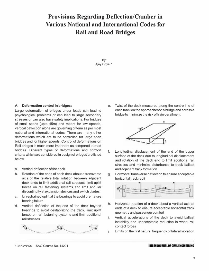
A. Deformation control in bridges: e. Twist of the deck measured along the centre line of
each track on the approaches to a bridge and across a Large deformation of bridges under loads can lead to bridge to minimize the risk of train derailmentpsychological problems or can lead to large secondary
stresses or can also have safety implications. For bridges
of small spans (upto 45m) and meant for low speeds,
vertical deflection alone are governing criteria as per most
national and international codes. There are many other
deformations which are to be controlled for large span
bridges and for higher speeds. Control of deformations on
Rail bridges is much more important as compared to road
bridges. Different types of deformations and comfort f. Longitudinal displacement of the end of the upper criteria which are considered in design of bridges are listed surface of the deck due to longitudinal displacement below. and rotation of the deck end to limit additional rail
stresses and minimize disturbance to track ballast a. Vertical deflection of the deck. and adjacent track formation
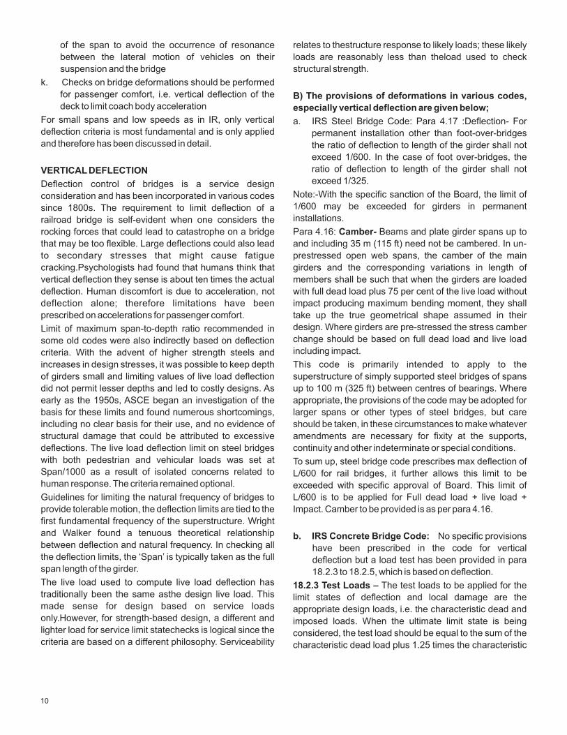
b. Rotation of the ends of each deck about a transverse g. Horizontal transverse deflection to ensure acceptable axis or the relative total rotation between adjacent horizontal track radiideck ends to limit additional rail stresses, limit uplift
forces on rail fastening systems and limit angular
discontinuity at expansion devices and switch blades
c. Unrestrained uplift at the bearings to avoid premature
bearing failure h. Horizontal rotation of a deck about a vertical axis at
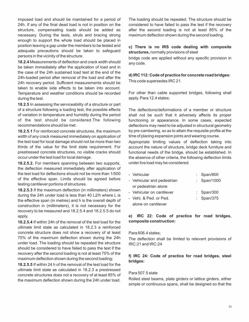
d. Vertical deflection of the end of the deck beyond ends of a deck to ensure acceptable horizontal track
bearings to avoid destabilizing the track, limit uplift geometry and passenger comfort
forces on rail fastening systems and limit additional i. Vertical accelerations of the deck to avoid ballast rail stresses.
instability and unacceptable reduction in wheel rail
contact forces
j. Limits on the first natural frequency of lateral vibration
By
Ajay Goyal *
IRICEN JOURNAL OF CIVIL ENGINEERING
Provisions Regarding Deflection/Camber in
Various National and International Codes for
Rail and Road Bridges
9
* CE/C/N/CR SAG Course No. 14201
of the span to avoid the occurrence of resonance relates to thestructure response to likely loads; these likely
between the lateral motion of vehicles on their loads are reasonably less than theload used to check
suspension and the bridge structural strength.
k. Checks on bridge deformations should be performed
for passenger comfort, i.e. vertical deflection of the B) The provisions of deformations in various codes, deck to limit coach body acceleration especially vertical deflection are given below;
For small spans and low speeds as in IR, only vertical a. IRS Steel Bridge Code: Para 4.17 :Deflection- For deflection criteria is most fundamental and is only applied permanent installation other than foot-over-bridges and therefore has been discussed in detail. the ratio of deflection to length of the girder shall not
exceed 1/600. In the case of foot over-bridges, the
ratio of deflection to length of the girder shall not VERTICAL DEFLECTIONexceed 1/325.Deflection control of bridges is a service design
Note:-With the specific sanction of the Board, the limit of consideration and has been incorporated in various codes 1/600 may be exceeded for girders in permanent since 1800s. The requirement to limit deflection of a installations.railroad bridge is self-evident when one considers the
rocking forces that could lead to catastrophe on a bridge Para 4.16: Camber- Beams and plate girder spans up to
that may be too flexible. Large deflections could also lead and including 35 m (115 ft) need not be cambered. In un-
to secondary stresses that might cause fatigue prestressed open web spans, the camber of the main
cracking.Psychologists had found that humans think that girders and the corresponding variations in length of
vertical deflection they sense is about ten times the actual members shall be such that when the girders are loaded
deflection. Human discomfort is due to acceleration, not with full dead load plus 75 per cent of the live load without
deflection alone; therefore limitations have been impact producing maximum bending moment, they shall
prescribed on accelerations for passenger comfort. take up the true geometrical shape assumed in their
design. Where girders are pre-stressed the stress camber Limit of maximum span-to-depth ratio recommended in change should be based on full dead load and live load some old codes were also indirectly based on deflection including impact.criteria. With the advent of higher strength steels and
increases in design stresses, it was possible to keep depth This code is primarily intended to apply to the
of girders small and limiting values of live load deflection superstructure of simply supported steel bridges of spans
did not permit lesser depths and led to costly designs. As up to 100 m (325 ft) between centres of bearings. Where
early as the 1950s, ASCE began an investigation of the appropriate, the provisions of the code may be adopted for
basis for these limits and found numerous shortcomings, larger spans or other types of steel bridges, but care
including no clear basis for their use, and no evidence of should be taken, in these circumstances to make whatever
structural damage that could be attributed to excessive amendments are necessary for fixity at the supports,
deflections. The live load deflection limit on steel bridges continuity and other indeterminate or special conditions.
with both pedestrian and vehicular loads was set at To sum up, steel bridge code prescribes max deflection of Span/1000 as a result of isolated concerns related to L/600 for rail bridges, it further allows this limit to be human response. The criteria remained optional. exceeded with specific approval of Board. This limit of
Guidelines for limiting the natural frequency of bridges to L/600 is to be applied for Full dead load + live load +
provide tolerable motion, the deflection limits are tied to the Impact. Camber to be provided is as per para 4.16.
first fundamental frequency of the superstructure. Wright
and Walker found a tenuous theoretical relationship b. IRS Concrete Bridge Code: No specific provisions between deflection and natural frequency. In checking all have been prescribed in the code for vertical the deflection limits, the ‘Span’ is typically taken as the full deflection but a load test has been provided in para span length of the girder. 18.2.3 to 18.2.5, which is based on deflection. The live load used to compute live load deflection has 18.2.3 Test Loads – The test loads to be applied for the traditionally been the same asthe design live load. This limit states of deflection and local damage are the made sense for design based on service loads appropriate design loads, i.e. the characteristic dead and only.However, for strength-based design, a different and imposed loads. When the ultimate limit state is being lighter load for service limit statechecks is logical since the considered, the test load should be equal to the sum of the criteria are based on a different philosophy. Serviceability characteristic dead load plus 1.25 times the characteristic
10
imposed load and should be maintained for a period of The loading should be repeated. The structure should be
24h. If any of the final dead load is not in position on the considered to have failed to pass the test if the recovery
structure, compensating loads should be added as after the second loading is not at least 85% of the
necessary. During the tests, struts and bracing strong maximum deflection shown during the second loading.
enough to support the whole load should be placed in
position leaving a gap under the members to be tested and c) There is no IRS code dealing with composite adequate precautions should be taken to safeguard structures, normally provisions of steel persons in the vicinity of the structure.
bridge code are applied without any specific provision in 18.2.4 Measurements of deflection and crack width should any code.be taken immediately after the application of load and in
the case of the 24h sustained load test at the end of the d) IRC 112: Code of practice for concrete road bridges:
24h-loaded period after removal of the load and after the This code supersedes IRC 21. 24h recovery period. Sufficient measurements should be
taken to enable side effects to be taken into account. For other than cable supported bridges, following shall Temperature and weather conditions should be recorded apply. Para 12.4 states;during the test.
18.2.5 In assessing the serviceability of a structure or part
of a structure following a loading test, the possible effects The deflections/deformations of a member or structure of variation in temperature and humidity during the period shall not be such that it adversely affects its proper of the test should be considered.The following functioning or appearance. In some cases, expected recommendations should be met. deflections may need to be adjusted in structural geometry
by pre-cambering, so as to attain the requisite profile at the 18.2.5.1 For reinforced concrete structures, the maximum time of placing expansion joints and wearing course.width of any crack measured immediately on application of
the test load for local damage should not be more than two Appropriate limiting values of deflection taking into thirds of the value for the limit state requirement. For account the nature of structure, bridge deck furniture and prestressed concrete structures, no visible cracks should functional needs of the bridge, should be established. In occur under the test load for local damage. the absence of other criteria, the following deflection limits
under live load may be considered.18.2.5.2. For members spanning between two supports,
the deflection measured immediately after application of
the test load for deflections should not be more than 1/500 - Vehicular : Span/800of the effective span. Limits should be agreed before - Vehicular and pedestrian : Span/1000testing cantilever portions of structures.
or pedestrian alone 18.2.5.3 If the maximum deflection (in millimeters) shown
- Vehicular on cantilever : Span/300during the 24h under load is less than 40 L2/h where L is
- Vehi. & Ped. or Ped. : Span/375the effective span (in metres) and h is the overall depth of
alone on cantileverconstruction in (millimeters), it is not necessary for the
recovery to be measured and 18.2.5.4 and 18.2.5.5 do not e) IRC 22: Code of practice for road bridges, apply.composite construction:18.2.5.4 If within 24h of the removal of the test load for the
ultimate limit state as calculated in 18.2.3 a reinforced
concrete structure does not show a recovery of at least Para 606.4 states;75% of the maximum deflection shown during the 24h The deflection shall be limited to relevant provisions of under load. The loading should be repeated the structure IRC:21 and IRC:24should be considered to have failed to pass the test if the
recovery after the second loading is not at least 75% of the f) IRC 24: Code of practice for road bridges, steel
maximum deflection shown during the second loading;bridges:
18.2.5.5 If within 24 h of the removal of the test load for the
ultimate limit state as calculated in 18.2.3 a prestressed Para 507.5 state
concrete structures does not a recovery of at least 85% of Rolled steel beams, plate girders or lattice girders, either the maximum deflection shown during the 24h under load. simple or continuous spans, shall be designed so that the
11
total deflection due to dead load, live load and impact shall cross and longitudinal level, track twist and alignment.
not exceed 1/600 of the span. Additionally deflection due to Following limits are prescribed. These limits are w.r.t live
live load + Impact shall not exceed L/800 load.
In cantilever arm, not more than L/300 due to dead load,
live load and impact. Not more than L/400 due to live load - Vertical deflection : L/800and impact - Angle of rotation at ends : 1/200Camber- Beams and plate girder spans up to and - Horizontal deflection : L/4000including 35 m need not be cambered. In open web spans,
- Skew of bridge : Max twist 1mm/mthe camber of the main girders and the corresponding
variations in length of members shall be such that when the Camber: It is desirable to provide camber of not more than girders are loaded with full dead load plus 75 per cent of the half the calculated live load deflection and this value live load without impact producing maximum bending should be limited to L/1500moment, they shall take up the true geometrical shape
assumed in their design. The camber diagram shall be j) UIC 774-3R: LWR on bridges:prepared.
Code prescribes deformation limits when bridges are
provided with LWRg) IRC 21: Code of practice for road bridges, - Maximum absolute displacement of deck due to concrete construction:
tractive/breaking forcesThis code has been superseded by IRC 112. - +/- 5 mm if no SEJ or SEJ at one endNo provision for deflection. Appendix 1 gives crack control - +/- 30 mm with SEJ on both endsparameters.
- Maximum relative displacement between track and
deck due to tractive/breaking forcesh) UIC776-3R: Deformation of Bridges:- 4 mmDeformation limits are given for vertical deflection, angle of
- Maximum displacement between the top of deck end rotation at ends, track twist and horizontal deflection of and the embankment or between two deck ends due to Railway bridges. The values given are for three speed deck bendingranges; up to 120kmph, up to 200 kmph and above 200
kmph. - 8 mm
- Maximum lift of deck on SEJ end
Values for speed range 1, values of vertical deflection and - To be specified by Railway, Primarily depends upon camber are as under. speed
• For spans more than 12m, an upward camber equal to
L/1000 under self weight can be given to improve k) AASHTO code G12.1.2003: Guidelines for design appearance. and constructability
• Due to LL and for speed range 1 and passenger This code is applicable to steel road bridges, does not give comfort as acceptable; for 2 adjacent decks vertical any provision for vertical deflection but gives detailed deflection should be < L/350; for 3 to 5 adjacent coverage on differential deflection on curved spans.spans and spans up to 25 m it should be < L/450 and
for more than 30 m spans it should be < L/800.l) AREMA: Chapter 8 on concrete bridges for Railways:
Flexural members of bridge structures shall be designed to So UIC code also limits deflection based on imposed loads have adequate stiffness to limit deflections or only and for speeds up to 120 kmph, values are as high as anydeformations that may adversely affect strength and L/350 for small spans and less than three adjacent spans serviceability of the structure at service load. to L/800 for larger and more than 3 adjacent spans. These Membershaving simple or continuous spans shall be provisions are quite liberal as compared to IRS provisions. designed so that the deflection due to service live load plus
impact doesnot exceed l/640 of the span.i) UIC 776-2R: Bridges for high and very high Deflections that occur immediately on application of load speeds: shall be computed by usual methods or formulas for elastic For high speeds tracks, low tolerances are essential for deflections, and moment of inertia of gross concrete
12
section may be used for uncracked sections. Additional state shall beappropriate to the structure and its intended
long-time deflection shall be computed taking into account use, the nature of the loading and the elementssupported
stresses in concrete and steel under sustained load and by it.Notwithstanding this requirement, the deflection for
including effects of creep and shrinkage of concrete and serviceability limit state under live load plus dynamic load
relaxation of pre-stressing steel. allowance shall be not greater than 1/600 of the span or
1/300 of thecantilever projection, as applicable.The live
load to be used for calculating deflection shall be LL m) AREMA: Chapter 15 on steel bridges for Railways:including dynamic load allowance, placed longitudinally in
For steel bridges, the deflection of the structure shall be each design laneto produce the maximum deflection,
computed for the live loading plus impact loading taking into account the accompanying lane factors.
conditionproducing the maximum bending moment at mid-
span for simple spans. The structure shall be so designed (a) Deflections do not infringe on clearance diagrams;that the computed deflection shall not exceed 1/640 of the
span length centre to centre of bearings for simple spans. (b) Hog deflection does not exceed 1/300 of the span;
andLateral deflection of spans shall be limited to 3/8 inch (10
mm) for tangent track as measured on a 62 foot (19meter) (c) No sag deflection occurs under permanent loads.
chord. On curved track, lateral deflection shall be limited to
1/4 inch (6 mm) as measured on a 31 foot(9.5 meter) When deflections are calculated for serviceability loads, chord. Allowable lateral deflection for spans shall be including dynamic allowance, 2/3 of the dynamic load calculated based on these limits taken insquared allowance shall be used.proportion to the span length under consideration.
For Rail Bridge: 8.9 Deflection: The deflection limits of a CAMBER: The camber of trusses shall be equal to the railway bridge under traffic for serviceability limit state shall deflection produced by the dead load plus a live load of be appropriate to the structure and its intended use, the 3,000 lb per footof track. The camber of plate girders more nature of the loading and the elements supported by it. than 90 feet in length shall be equal to the deflection Notwithstanding this requirement, the deflection of railway produced by thedead load only. Plate girders 90 feet or less bridges for serviceability limitstate under live load plus in length and rolled beams need not be cambered. dynamic load allowance shall be not greater than 1/640 of Composite spans shall be designed so that the deflection, the span and 1/320 of the cantilever projection.computed using the composite section, for the live load NOTE: In order not to detract from their appearance, plus impact load condition does not exceed 1/640 of the bridges should be designed so that their hogdoes not span length center to center of bearings. exceed 1/300 of the span and they do not sag under Camber: The beams of composite construction shall be permanent loads. Railway bridges shall not deflect so that cambered when the dead load deflection exceeds 1 inch. they infringe clearance diagrams.
n) AS : 5100.1 Bridge design, Scope and general p) BS 5400-1, General statements:principles: Para 3.4: The deflection of the structure or any part of it CAMBER on Railway bridge superstructures with open should not be such as to affect its appearance adversely, deck or directly fixed track, and span lengthsgreater than violate minimum specified clearances, or cause drainage 20 m shall be cambered. The camber shall be determined difficulties. The structure may need to be cambered to such that the railwaytrack shall be at its theoretical level counter these effects. Minimum specified clearances under the effects of the permanently applied loads; should be maintained under the action of load combination forexample, dead load, superimposed dead load, long- 1 for the serviceability limit state. The appearance and term pre-stressing, shrinkage and creepeffects where drainage characteristics of the structure should be applicable, and half of the design railway traffic loads, considered under the action of permanent loads only. excluding dynamicload allowance.
q) BS 5400-2, Design Loads: For the purpose of o) AS : 5100.2 Bridge design, Design loads: calculating deflection and camber, the nominal loads shall
For Road bridge: Para 6.11 Deflection: The deflection be adopted.
limits of a road bridge under traffic for serviceability limit
13
r) BS 5400-3, Code of practice for design of steel • Vertical deflection of the end of the deck beyond
bridges: bearings to avoid destabilising the track, limit uplift
forces on rail fastening systems and limit Para 5.7 Camber: The structure may need to be additional rail stressescamberedto achieve a satisfactoryappearance of the
bridge. In this connection a sagging deflection of a • Twist of the deck measured along the centre line of
nominally straight soffit of 1/800 of the span should not be each track on the approaches to a bridge and
exceeded. The cambered shape of the structure under the across a bridge to minimise the risk of train
action of the actual dead andsuperimposed dead loads derailment
should be as specified or approved by the Engineer. • Rotation of the ends of each deck about a
transverse axis or the relative total rotation
between adjacent deck ends to limit additional rail s) BS 5400-4, Code of practice for design of concrete stresses, limit uplift forces on rail fastening bridgessystems and limit angular discontinuity at No specific provision for deflection, 5400-1 and 2 shall expansion devices and switch blades.apply
• Longitudinal displacement of the end of the upper
surface of the deck due to longitudinal t) BS 5400-5, Code of practice for design of composite
displacement and rotation of the deck end to limit bridges
additional rail stresses and minimise disturbance
to track ballast and adjacent track formation.Para 5.5 Deflections: Recommendations for
• Horizontal transverse deflection to ensure deflectionsand general guidance on their calculation are
acceptable horizontal track radii.givenin Part 1. In calculatingdeflections consideration
• Horizontal rotation of a deck about a vertical axis at should be given to thesequence of construction and,
ends of a deck to ensure acceptable horizontal where appropriate,proper account should be taken of the
track geometry and passenger comfort.deflections ofthe steel section due to loads applied to it
• Limits on the first natural frequency of lateral prior tothe development of composite action and of vibration of the span to avoid the occurrence of partialcomposite action where deck slabs are cast in resonance between the lateral motion of vehicles stage.on their suspension and the bridge.
u) EN 1990: Basis of Structural design for Railway (i) The maximum deck twist t of a track gauge of 1,435 m Bridges
measured over a length of 3m should not exceed the Excessive bridge deformations can endanger traffic by
valuescreating unacceptable changes in vertical and horizontal
track geometry, excessive rail stresses and vibrations in Speed range V Maximum twist t bridge structures. Excessive vibrations can lead to ballast
instability and unacceptable reduction in wheel rail contact (km/h) (mm/3m)
forces. Excessive deformations can also affect the loads V ≤ 120 ≤ 4.5imposed on the track/ bridge system, and create
120 < V ≤ 200 ≤ 3.0conditions which cause passenger discomfort. V > 200 ≤ 1.5Deformation and vibration limits are either explicit or
implicit in the bridge stiffness criteria given in the code.
Checks on bridge deformations shall be performed for (ii) Vertical deformation of the deck loaded with the traffic safety purposes for the following items. classified characteristic vertical loading, the maximum
Vertical accelerations of the deck to avoid ballast instability total vertical deflection measured along any track due to
and unacceptable reduction in wheel rail contact forces rail traffic actions should not exceed L/600.
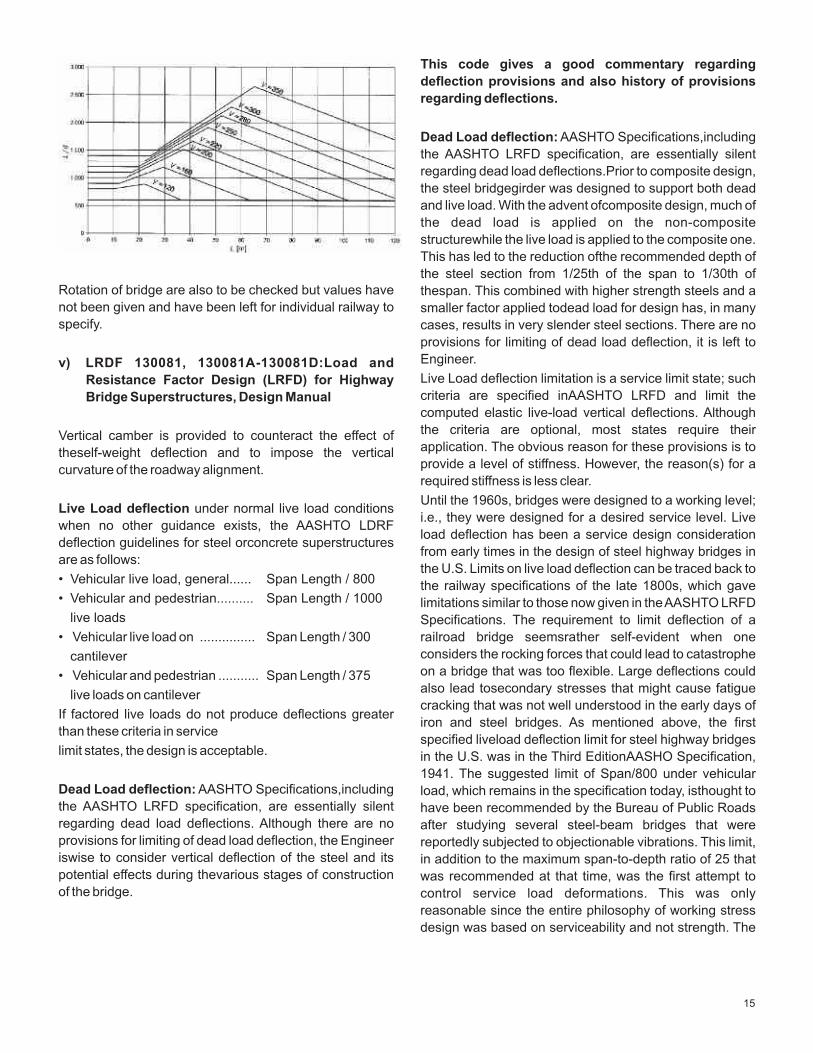
• Vertical deflection of the deck throughout each For comfort criteria, maximum permissible vertical
spanto ensure acceptable vertical track radii and deflection δ for railway bridges with 3 or more successive
generally robust structures. simply supported spans corresponding to a permissible
vertical acceleration of 1 m/s² in a coach for speed V is • Unrestrained uplift at the bearings to avoid given as per following diagram.premature bearing failure
14
This code gives a good commentary regarding
deflection provisions and also history of provisions
regarding deflections.
Dead Load deflection: AASHTO Specifications,including
the AASHTO LRFD specification, are essentially silent
regarding dead load deflections.Prior to composite design,
the steel bridgegirder was designed to support both dead
and live load. With the advent ofcomposite design, much of
the dead load is applied on the non-composite
structurewhile the live load is applied to the composite one.
This has led to the reduction ofthe recommended depth of
the steel section from 1/25th of the span to 1/30th of Rotation of bridge are also to be checked but values have thespan. This combined with higher strength steels and a not been given and have been left for individual railway to smaller factor applied todead load for design has, in many specify. cases, results in very slender steel sections. There are no
provisions for limiting of dead load deflection, it is left to
Engineer.v) LRDF 130081, 130081A-130081D:Load and Live Load deflection limitation is a service limit state; such Resistance Factor Design (LRFD) for Highway criteria are specified inAASHTO LRFD and limit the Bridge Superstructures, Design Manualcomputed elastic live-load vertical deflections. Although
the criteria are optional, most states require their Vertical camber is provided to counteract the effect of application. The obvious reason for these provisions is to theself-weight deflection and to impose the vertical provide a level of stiffness. However, the reason(s) for a curvature of the roadway alignment.required stiffness is less clear.
Until the 1960s, bridges were designed to a working level; Live Load deflection under normal live load conditions
i.e., they were designed for a desired service level. Live when no other guidance exists, the AASHTO LDRF
load deflection has been a service design consideration deflection guidelines for steel orconcrete superstructures
from early times in the design of steel highway bridges in are as follows:
the U.S. Limits on live load deflection can be traced back to • Vehicular live load, general...... Span Length / 800
the railway specifications of the late 1800s, which gave • Vehicular and pedestrian.......... Span Length / 1000 limitations similar to those now given in the AASHTO LRFD
live loads Specifications. The requirement to limit deflection of a
• Vehicular live load on ............... Span Length / 300 railroad bridge seemsrather self-evident when one
considers the rocking forces that could lead to catastrophe cantileveron a bridge that was too flexible. Large deflections could • Vehicular and pedestrian ........... Span Length / 375also lead tosecondary stresses that might cause fatigue
live loads on cantilevercracking that was not well understood in the early days of
If factored live loads do not produce deflections greater iron and steel bridges. As mentioned above, the first
than these criteria in servicespecified liveload deflection limit for steel highway bridges
limit states, the design is acceptable. in the U.S. was in the Third EditionAASHO Specification,
1941. The suggested limit of Span/800 under vehicular Dead Load deflection: AASHTO Specifications,including load, which remains in the specification today, isthought to the AASHTO LRFD specification, are essentially silent have been recommended by the Bureau of Public Roads regarding dead load deflections. Although there are no after studying several steel-beam bridges that were provisions for limiting of dead load deflection, the Engineer reportedly subjected to objectionable vibrations. This limit, iswise to consider vertical deflection of the steel and its in addition to the maximum span-to-depth ratio of 25 that potential effects during thevarious stages of construction was recommended at that time, was the first attempt to of the bridge. control service load deformations. This was only
reasonable since the entire philosophy of working stress
design was based on serviceability and not strength. The
15
advent of higher strength steels and concomitant only bridges designed forpedestrian traffic or stationary
increases in design stressesled to concern about the effect veh i c l es be l im i t ed i n mo t i on by such a
of live load deflection on economics. As early as the1950s, serviceabilitycriterion. The issue of bridge vibrations and
ASCE began an investigation of the basis for these limits their relation to human response, alongwith the
and foundnumerous shortcomings, including no clear development of a reasonable means of controlling bridge
basis for their use, and no evidence of structural damage vibrations toensure adequate creature comfort, remains a
that could be attributed to excessive deflections. complex and subjective issue in need of further study.
Competition with pre-stressed concrete bridges in the Other suggested live load deflection limits contained in 1960s led to further investigations as to the need for this AASHTO LRFD include a limit of Span/300 for vehicular serviceability limit. Field investigations at that time, again, loads on cantilever arms, and alimit of Span/375 for showed no direct correlation. Not only did the limitation combined vehicular and pedestrian loads on cantilever remain, but In the early 1960s an additional limit was arms. In checking all the deflection limits, the ‘Span’ is introduced; the live load deflection limit on steel bridges typically taken as the full spanlength of the girder. As with both pedestrian and vehicular loads was set at mentioned previously, the limit on span-to-depth ratio for Span/1000 as a result of isolated concerns related to continuous spans was often determined by defining the human response. The criteria remained optional. One span as the length betweenpoints of permanent load legend has it that this limitarose when a mother and wife of contraflexure. This led to shallower bridges with a political figure who was pushing her baby in acarriage anincreased flexibility when the limiting live load deflection across a bridge attributing her baby awakening to vibration was defined based on theactual span. Some states of the bridge. This complaint prompted the state’s governor conservatively limited deflection by using the to chastise the State Bridge Engineer. The issue of human distancebetween points of permanent load contraflexure comfort becomes a serviceability issue when people who in computing the permissibledeflection. Field tests have might use a bridge find its motion objectionable. This is a confirmed that decks of continuous composite girders departure from the other structural criteria provided in the innegative moment regions actually behave compositely. Specification. The complex issue of the human response Tradition has assumedthose regions to be non-composite. of occupants of moving vehicles and of pedestrians to Use of the entire deck obviously reduces thecomputed motion has been extensively studied. However, there still deflections and brings them closer to actual with regard to are nodefinitive guidelines on the tolerable limits of the behavior ofdynamic motion or static deflection to ensure creature the deck.comfort. Guidelines for limiting the natural frequency of
bridges to provide tolerable motion are contained in the The live load used to compute live load deflection has
Ontario Highway Bridge Design Code, in which the traditionally been the same asthe design live load. This
deflection limits are tied to the first fundamental frequency made sense for design based on service loads
of thesuperstructure. These limits are provided in the form only.However, for strength-based design, a different and
of graphs and are separated in conjunction with the lighter load for service limit statechecks is logical since the
anticipated pedestrian use. These provisions require that criteria are based on a different philosophy. In
thedesigner compute the natural frequency of the strengthdesign, the capacity of the structure is challenged.
composite bridge. Wright and Walkerfound a tenuous Serviceability relates to thestructure response to likely
theoretical relationship between deflection and natural loads; these likely loads are reasonably less than the load
frequency. They observed that user comfort was an used to check structural strength. However, even in
important factor. They reported thatservice load design, liveload application has often been
Psychologists had found that humans think that vertical different from application for design of the elements. For
deflection they sense is about ten times the actual example, the 1941 AASHO Bridge Specifications
deflection. Wright and Walker postulated that human permitted the Engineer to compute the moment in a
discomfort is due to acceleration, not deflection alone. stringer for deflection purposes by assuming that all of the
They proposed a parameter, defined as the dynamic lanes are loaded with the design load and that the resulting
component of acceleration in the fundamental mode o load is uniformly distributed equally to all stringers where
fvibration, be limited to 100 in2/sec. The authors suggest adequate depth diaphragms or cross-framesexist. Some
that such acceleration is within the tolerable range have since interpreted this provision to allow a reduction in
experienced in building elevators contemporary with the load basedon the multiple presence factor provision. The
writing of the paper (1960s). They further suggested that
16
practice of loading all lanes appearsto be at odds, at least deflection resultingfrom: 1) the design truck alone
in some cases, with the provision in the 1935 Edition, (including the 33 percent dynamic load allowance), or2)
which states: “In calculating stresses in structures which the design lane load in conjunction with 25 percent of the
supportcantilevered sidewalks, the sidewalk shall be design truck (includingthe 33 percent dynamic load
considered as fully loaded on only oneside of the structure allowance). As specified in AASHTO LRFD, a load factor of
if this condition produces maximum stress.” This 1.0 is applied according to the Service I load combination.
provisionreveals an understanding that loading on the far This special loading is intended to produce deflections
side of a multi-stringer bridgeunloads the near side; this similar to thosedue to HS20. It was decided by the
understanding has been borne out in refined analyses. specification writers that it was unnecessary tocheck live
Ifone visualizes the entire cross-section rotating as a rigid load deflections for the heavier HL-93 design live load
body under each of theabove load cases, as assumed in used for strengthchecks. The HL-93 design truck has the
the development of the l ive-load distribution same weight as an HS20 truck. The HL-93design lane load
factorEquation 2.1 for exterior girders given in DM Volume also has the same weight as that specified for HS20. The
1, Chapter 2, it is apparent thatthe opposite side of the use of 25percent of the design truck (0.25 * 72 kips = 18
bridge rises when one side is loaded. Hence, from the time kips) is similar to the HS20 singleconcentrated load of 18
kips used in combination with the HS20 lane load it was introduced, the assumption of uniform loading of fordetermining bending moments and deflections in longer girders for computation ofdeflection was known to be a spans. Of course, theresulting deflections are less than very blunt instrument to simply require less stiffness.With those computed for HS25; hence, the AASHTOLRFD live the adoption of Load Factor Design (LFD), many states load for deflection is more lenient in this case.increased live load toHS25 for strength. Some used the
HS25 design live load to compute live loaddeflection; The provisions of AASHTO LRFDfor straight-girder
however, others departed from using the same live load for bridges allow allinteger 12-foot wide design lanes to be
strength andservice as discussed above and used the loaded with all girders assumed to deflectequally. This
HS20 live load for checking deflection. clause should only be applied when the longitudinal
stiffness of theindividual girders at all cross-sections is the The use of a 25-percent larger live load eliminated some of same. Cases where the clause shouldnot be applied the economy possiblewith the lower factor applied to dead include cases with skewed supports, different girder load in LFD. Since the same factors were notused for depths, or girderswith different flange sizes. The deflection, it was logical to keep the same traditional live assumption of equal live load deflection is notapplicable to load.The combination of moving from 33- to 70-ksi yield-horizontally curved bridges. The AASHTO LRFD stress steel, along with theintroduction of composite specifications aresilent with regard to the application of this design, LFD and then LRFD, and the increase of the span-assumption to bridges with skewedsupports. The live load to-depth ratio for steel girders from 25 to 30 had a net effect deflection of individual girders is to be computed for of roughly increasingthe permitted live load deflection by curvedgirdersbased on analysis of the superstructure asa about threefold. Field experience of bridgesbuilt has structural system with live loads applied according the provided scant evidence that the increased flexibility of loading provisions of theSpecifications.There are other steel bridges hadled to any reduced functionality. bridges where the equal deflection assumption is not Projection of this trend into the future would implythat the rational.Loading of all lanes simultaneously of relatively limit on live load deflection should be infinity. However, the wide bridges may not give a rationaldeflection. This is First TacomaNarrows Bridge and common sense clearly the case if one visualizes the bridge cross-section intervene. It seems that some logical limitexists, but such a rotatingas a rigid body under load, much as assumed in the limit has proved elusive. It has also been shown that special analysis for determiningthe wheel-load distribution computationof live load deflection as specified in AASHO factor for exterior girders.and AASHTO is not likely to predict theactual deflection.
And so, as the live load deflection limit has become Concrete barriers and sidewalks, and even railings, often
anincreasingly critical factor in the design of steel bridges contribute to the stiffnessof composite superstructures at
utilizing the higher-strengthhigh performance steels service load levels. Therefore, AASHTO permits the entire
(HPS), an additional investigation has recently width of the roadway and the structurallycontinuous
beenlaunched into the potential need for improved live portions of railings, sidewalks and barriers (i.e. continuous
load deflection criteria for steelbridges.When applying the cast-in-placebarriers) to be included in determining the
current live load deflection criteria, AASHTO LRFD composite stiffness for deflectioncalculations. Because
requires that the deflection be taken as the larger of the the inclusion of the concrete items other than the deck
17
cancause complications in the calculation of the stress in theconcrete deck due to either load combination
composite stiffness (and in modelling with regard to their Service II or due to the factoredconstruction loads exceeds
inclusion in refined analyses), it is suggested that these the factored modulus of rupture of the concrete.
items beignored. If the parapets are on the exterior of the Underthese conditions, the crack size is felt to be
deck, they tend to stiffen theexterior girders drawing load controlled to a degree such that theconcrete deck may be
to those girders. Hence, computation of the deflectionsof considered effective in tension for computing the flexural
the critical exterior based on refined analysis methods stresses acting on the composite section at the service
show that the computeddeflections are not materially limit state. When the aboveconditions are satisfied, the
reduced by the consideration of the parapets. Engineer is strongly encouraged to consider theconcrete
deck to be fully effective in calculating all Service II flexural AASHTO LRFD deals with checks related to the control stresses, as thisassumption better reflects the actual ofpermanent deformations in steel I-girder bridges under conditions in the bridge.repeated severe trafficloadings. Control of permanent
deformations is important to ensure good ridingquality.To
control permanent deformations according to AASHTO C ) Recent Railway designs in IR:LRFD,checks are to be made on the flange stresses and Two important bridges are under construction in Indian for potential web bend bucklingunder the Service II load Railways, one Chenab bridge in USBRL project and combination. The standard design Service IIloading is another at Bogibheel in NFR. defined as 1.0DC + 1.0DW + 1.3(LL+IM), where DC
represents thecomponent dead loads, DW represents the The criteria adopted in Chenab bridge is based on UIC
wearing surface and utility loads and(LL+IM) represents 776-3R.
the design live load plus the dynamic load allowance Structural Deformation Limit: All the structural deformation placed inmultiple lanes. As will be discussed later on in the limits prescribed in UIC 776-3R shall be complied with chapter, checks are also to bemade to prevent slip in slip-wind pressure of 150 kg/sqm, considering the least critical bolted connections under the Service II loading.The favorable case with one or two tracks loaded and other Service II load combination is intended to be equivalent to forces as given in Table — 2 of Annexure B' and the load the Overload given inthe AASHTO Standard combinations given in para 2.0& 3.0 of Annexure 'C' for Specifications. In the AASHTO Standard Specifications, service conditions.the overload is intended to represent live loads that can be Vertical Deflection Limit: The ratio of span to maximum allowed on the structure on infrequent occasions without vertical deflection shall not be less than 400 given in Table causing permanent damage. The standard design 4 of UIC 776-3R for the case of one or two adjacent decks overload (i.e. for loadings of H20 or above) is defined as D case for speed range 1 for high quality passenger line.+ 5/3(L+I), where Drepresents the dead load and (L+I) Lateral displacement Limit: The horizontal deformation of represents the design live load plus impactplaced in bridge deck should not cause a horizontal change of angle multiple lanes. Although the live load is to be placed in at a free end exceeding 0.0035 radian, nor a change of multiple lanes fordesign purposes, it can be shown that the curvature radius of less than 3500 m for several adjacent live load factor of 5/3 essentially makesthe loading decks as given in Table 2 of UIC 776- 3R for speed range 1.equivalent to two times the design live load placed in a
single lane.In both the AASHTO LRFD Specifications and
the Standard Specifications, whenthese checks are to be The criteria adopted in Bogibheel bridge is based on applied to a design permit load, consideration should UIC and EURO codes.begiven to reducing the load factor on the live load from 1.3 The reason for adopting international codes is that IRS and 5/3, respectively, to1.0 since the load is known.As codes don’t give adequate provisions for long spans. discussed previously, under certain conditions, AASHTO Deflection criteria ideally must be based on performance LRFDpermits flexural stresses caused by Service II loads requirements and also be independent of material & applied to the composite sectionto be computed assuming method of construction.All international codes have the concrete deck is effective for both positive andnegative deflection criteria based on live loads only.Besides vertical flexure for the permanent deflection design checks. As deflections, other deformation criteria also must be specified inAASHTO LRFD, those conditions are that included. The limiting value of L/600 for vertical deflection shear connectors must beprovided along the entire length based on DL+LL+IL as in IRS steel bridge code cannot be of the girder and that the minimum one percentlongitudinal met with by any rational design; in fact design with this deck reinforcement must be placed wherever the tensile criteria may be impossible.
18
IRS Steel Bridge L/600 for DL +LL +IL Applicable to Steel Rail
Codes Code Bridges on IR
Concrete Bridge Code No Limits but a acceptance test Applicable to Concrete Rail bridges on IR
No code for Composite Br. Generally both Steel and concrete Applicable to Composite Rail bridges
code limits are adopted on IR
IRC IRC 112 L/800 for LL+IL Applicable to Concrete Road Bridges
Codes in India
IRC 24 L/600 for DL+LL+IL Applicable to Steel Road Bridges in India
and additionally L/800 for LL+IL
IRC 21 No provision other than Code is superseded by IRC 112
crack control
IRC 22 As per IRC 21 and IRC 24 Applicable to Composite Road
Bridges in India
UIC UIC 776-2R L/800 for LL+IL; Angle of Applicable to High speed rail bridges
Codes rotation 1/200
UIC 776-3R L/350 to L/800 for LL+IL for Applicable to Rail bridges
speeds less than 120 kmph
various span combinations
AREMA Part 15 L/640 for LL+IL Applicable to Steel and Composite
Rail bridges
Part 8 L/640 for LL+IL Applicable to Concrete Rail bridges
AS AS 5100.2 Road Bridge: L/600 for LL+IL Applicable to Road and Rail Bridges
(IL can be taken as 2/3)
Rail Bridge: L/640 for LL+IL
(IL can be taken as 2/3)
BS BS 5400-1 Should be limited so that does Applicable to all bridges
not affect appearance
BS 5400-3 Sagging Deflection of L/800 Applicable to Steel Rail and Road Bridges
should not be exceeded.
Deflection due to DL + SIDL can
be accounted in camber
BS 5400-4 No limits given, to be checked for Applicable to Concrete Rail and
crack control Road Bridges
BS 5400-5 Provision of general code, part 3 Applicable to Composite Rail and
and part 4 to be followed. Road Bridges
EURO EN 1990 L/600 for LL+IL for freight load. Applicable to Rail bridges
For passenger separate graph is
given based on speed.
LDRF 130081: L/800 for LL+IL Applicable to Road Bridges
130081A:
130081D
19
As can be inferred from above table that all foreign codes on LL+IL only as per international practice. A value of
have deflection criteria based on live load only. Normally L/800 can be adopted (satisfies AREMA, AS code and
deflection due to dead loads are either ignored for small UIC).
spans or are compensated by providing suitable camber
for longer spans. Deflection due DL should be covered in camber. For concrete bridges, normally dead weight is Additional upward camber up to L/1000 should be proportionately quite high in comparison to live load, DL provided. For open web girders camber criteria deflections are covered in camber and Live load given in IRS steel bridge code is adequate.deflections which are expected to be small is not directly Where camber is not provided in small deck spans, covered in design; deflection is indirectly controlled by total deflection including for DL should be limited to controlling crack width in concrete. IRS concrete bride L/600.code is based on BS5400, therefore it does not have any
The above provision should be applicable for speeds up deflection criteria; deflection is taken care of by upward
to 120-130 kmph and spans up to 30m. For higher camber given to bridge while pre-stressing and by
speeds or longer spans, detailed deformation criteria as controlling crack width. However in Indian Railways
per UIC 776-3R should be adopted. there is unreasonable practice of following criteria of
Steel Bridge Code. ROAD BRIDGES: IRC codes have adopted values
Road over bridges in IR are designed as per IRC codes. given in LRFD based on LL+IL correctly but have added
IRC codes have adopted criteria based on LDRF which additional requirement as per IRS steel bridge code
limits deflection based on Live load (L/800) but has which is based on DL+LL+IL. In IRC codes, limit of L/600
additionally inserted criteria as per IRS steel bridge based on DL+LL+IL for steel and composite bridges
code, which is limiting deflection to L/600 for DL+LL+IL. taken from IRS code is unnecessary. For concrete
This criteria of L/600 for DL+LL+IL is applicable to steel bridges provisions are adequate.
and composite bridge. Additional criteria of L/600 for Where camber is provided, deflection due DL DL+LL+IL is unnecessary in IRC codes.
should be covered in camber. Additional upward
camber up to L/1000 should be provided.E) Recommendations:
Where camber is not provided in small deck spans, Rail Bridges: In IRS codes criteria for deflection for steel,
total deflection including concrete and composite deck bridges should be based
for DL should be limited to L/600.
20
Sr.No Codes/Manuals Last Correction Slip
1 Indian Railways Permanent Way Manual(second Reprint-2004) 135 dt 07.05.2014
2 Indian Railways Bridge Manual-1998 29 dt 15.04.2014
3 Indian Railways Works Manual-2000 10 dt 17.02.2005
4 Manual of Instructions on long Welded rails-2006(II reprint-2005) 15 dt 04.06.2012
5 Manual for Flash Butt welding of Rails(reprint-2012) 01 dt 14.08.2012
6 Manual for Fusion welding of rails by the Alumino Thermit Process nil
(Revised 2012)
7 Manual for Ultrasonic testing of rails & welds (revised 2012) nil
8 Manual for Glued insulated rail joints-1998 05 dt 28/08/2012
9 Indian Railways Track Machine Manual (2000) 17 dt 21.02.2014
10 Manual of Inspection schedules for officials of engg. Dept-2000 nil
11 Railways (opening for public Carriage of Passengers)Rules-2000 nil
12 Indian Railways Schedule of Dimensions 1676 gauge revised 2004 15 dt 19.06.2014
13 Indian Railways code for the engg dept (third Reprint-1999) 48 dt 01.05.2014
14 Guidelines for Earthwork in Railway projects-2003 01 dt 22.07.2004
15 General Condition of Contract (July 2013) 03 dt 07.11.2013
Details of Latest Correction Slips
21
Introduction:
Construction sector has taken a shape of industry and has AIMS AND OBJECTIVES:
registered enormous growth in recent years worldwide. 1. TO STUDY IS CODES, PROVISIONS OF Construction industry is essential for infrastructure CONTRACT DOCUMENTS AND GENERAL development and makes significant contribution to the CONDITIONS OF CONTRACT FOR RAILWAY national economy. Construction works are still labour TOWARDS SAFETY PROVIS IONS FOR oriented and provides employment to the large number of CONSTRUCTION.people. However, these construction workers are exposed 2. T O I D E N T I F Y P O S S I B L E S A F E T Y to wide varieties of serious hazards, despite advancement HAZARDS/ACCIDENTS.of technology in construction sector. Therefore, safety at
3. TO SUGGEST PRECAUTIONARY/PREVENTINE work site is of paramount importance. Safety of personnel
MEASURES.engaged in building construction, building construction
material, machinery, plants & equipments and surrounding BUREAU OF INDIAN STANDARD & SPECIAL properties can be achieved by proper planning, design and PUBLICATIONS AVAILABLE FOR CONSTRUCTION implementation of safety codes.SAFETY:
By
B. K. Tirkey*
IRICEN JOURNAL OF CIVIL ENGINEERING
Safety in Building Construction
* CE/CR
IS:3696 Safety code for scaffolds and ladders
(Part-I)-1987 Scaffolds
(Part-II)-1991 Ladders
IS:3764-1992 Excavation work-Code of safety.
IS:4082-1996 Stacking and storage of construction materials and components at site-Recommendation.
IS:4130-1991 Demolition of building-Code of Safety.
IS:4912-1978 Safety requirements for floor and wall openings, railing and toe boards.
IS:5121-1969 Safety code for piling and other deep foundations.
IS:5916-1970 Safety code for construction involving use of hot bituminous materials.
IS:7205-1974 Safety code for erection of structural steel work.
IS:7969-1975 Safety code for handling and storage of building materials
SAG Course No. 14201
22
IS:8989-1978 Safety code for erection of concrete framed structures
IS:13415-1992 Safety code for protective barrier in and around buildings
IS:13416 Recommendations for preventive measures against hazards at work places.
(Part- I)-1992 Falling material hazards prevention.
(Part-II)-1992 Fall prevention.
(Part-III)-1994 Disposal of debris.
(Part-IV)-1994 Timber structures.
(Part-V)-1994 Fire protection.
IS:13430-1992 Code of practice for safety during additional construction and alteration to existing buildings.
SP:62-1992 Handbook on building construction practices (excluding electrical works).
SP:70-2001 Handbook on construction safety practices
Provisions available in General Conditions of Contract Contractor shall at his own cost provide the materials
and Standard Specification 2001 (SER): for and execute all shoring, timbering and strutting
works as is necessary for the suitability and safety of
all structures, excavations and works and shall ensure Working during night: Contractor shall not carry out that no damage, injury or loss is caused or likely to be any work between sun-set and sun-rise without the caused to any person or property.previous permission of the Engineer.
Roads and Water Courses: Existing roads or water Damage to Railway property or private life and courses shall not be blocked, cut through, altered, property: The Contractor shall be responsible for all diverted or obstructed in any way by the Contractor risks to the works and for trespass and shall make except with the permission of the Engineer.good at his own expense all loss or damage whether to
Provision of access to premises: During progress of the works themselves or to any other property of the work in any street or thorough-fare, the Contractor Railway or the lives, persons or property of others from shall make adequate provision for the passage of whatsoever cause in connection with the works. until traffic, for securing self access to all premises they are taken over by the Railway. and this although approached from such street or thoroughfare and for all reasonable and proper precautions may have been any drainage, water supply or means of lighting which taken by the Contractor, and in case the Railway shall may be interrupted by reason of the execution of the be called upon to make good any costs, loss or works and shall erect and maintain at his own cost damages, or to pay any compensation, including that barriers, lights and other safeguards as prescribed by payable under the provisions of the Workmen’s the Engineer, for the regulation of the traffic, and Compensation Act or any statutory amendments provide watchmen necessary to prevent accidents.thereof to any person or persons sustaining damages
as aforesaid by reason of any act, or any negligence or Safety of Public: The Contractor shall be responsible
omissions on the part of the Contractor. to take all precautions to ensure the safety of the public
whether on public or Railway property and shall post Provision of efficient and competent staff: The such look-out men as may in the opinion of the Contractor shall place and keep on the works at all Engineer be required to comply with regulations times efficient and competent staff to give the pertaining to the work.necessary directions to his workmen and to see that
they execute their work in sound and proper manner Use of Explosives: Explosives shall not be used on
and shall employ only such supervisors, workmen and the works or on the site by the Contractor without the
labourers in or about the execution of any of these permission of the Engineer and then only in the
works as are careful and skilled in the various trades manner and to the extent to which such permission is
and callings. given. Where explosives are required for the works,
they shall be stored in a special magazine to be Precaution during progress of works: During the provided by and at the cost of the Contractor in execution of works, unless otherwise specified the
23
accordance with the Explosive Rules. The Contractor gangway or the stairway is more than 3.5 metres
shall obtain the necessary license for the storage and above ground level or floor level they should be closely
the use of explosives. boarded, should have adequate width and should be
suitably fastened as described in the Para above. Suspension of works: The Contractor shall on the
order of the Engineer suspend the progress of the Safe means of access shall be provided to all working
works or any part thereof for such time or times and in platform and other working places. Every ladder shall
such manner as the Engineer may consider necessary be securely fixed. No portable single ladder shall be
and shall during such suspension properly protect and over 10 metres in length while the width between side
secure the work so far as is necessary in the opinion of rails in swung ladder shall in no case be less than 300
the Engineer. If such suspension is: mm. for ladder up to and including 3.5 metres in length.
• Provided for in the contract, or For longer ladders this width should be increased by at
least 20 mm. each additional metre of length. Uniform • Necessary for the proper execution of the works or by steps spacing shall not exceed 300 mm. Adequate the reason of weather conditions or by some default on precautions shall be taken to prevent danger from the part of the Contractor, and orelectrical equipment. No materials on any of the sites • Necessary for the safety of the works or any part of work shall be so stacked or placed so as to cause thereof.danger or inconvenience to any persons or the public.
Reporting of Accidents to Labour: The Contractor The Contractor shall provide all necessary fencing and
shall be responsible for the safety of all employees lights to protect the public from accident.
directly or through petty contractors or sub-contractor Demolition: Before any demolition work is commenced employed by him on the works and shall report serious
and also during the process of work.accidents to any of them however and wherever • All roads and open area adjacent to the work site shall occurring on the works to the Engineer or the
either be closed or suitably protected.Engineer’s Representative and shall make every
arrangements to render all possible assistance. • No electric cable or apparatus which is liable to be a
source of danger over a cable or apparatus used by the
operator shall remain electrically charged.Provisions available in the Contract Document • All practical steps shall be taken to prevent danger to (ECoR/Construction Organization):
persons employed from risk of fire or explosives or Suitable scaffolds should be provided for workmen for flooding. No floor, roof or other part of the building shall all works that cannot be safely done from the ground or be so over loaded with debris or materials as to render from solid construction except for such short periods it unsafe.work as can be done safely from ladders. When a
All necessary personal safety equipment as ladder is used an extra labour shall be engaged for considered adequate by the Engineer-in-charge holding the ladder and if the ladder is used for carrying should be kept available for the use of the persons materials as well, suitable foot holds and handholds employed in the site and maintained in a condition shall be given an inclination not steeper than 1 to 4 suitable for immediate use and the contractor should (1 Horizontal to 4 Vertical).take adequate steps to ensure proper use of Scaffolding or staging more than 3.5 metres above the equipment by these concerned.ground or floor, swung or suspended from an overhead
• Workers employed on mixing asphaltic materials support or erected with stationery support shall have a cement and mortar shall be provided with protective guard rail properly attached, bolted, bracketed and goggles.otherwise secured at least 1 metre high above the floor
or platform of such scaffolding or staging and • Those engaged in white washing and mixing or
extending along the entire length thereof with only stacking of cement bags or any materials which are
such opening as may be necessary for the delivery of injurious to the eye shall be provided with protective
materials. Such scaffolding or staging shall be goggles.
fastened as to prevent it from swaying from the • Those engaged in welding works shall be provided building or structure. with welder’s protective eyesight lids.
Working platform gangways and stairways should be • Stone breakers shall be provided with protective so constructed that they should not sway unduly or goggles and protective clothing and seated at unequally and where the height of the platform or the sufficiently safe intervals.
When the work is done near any place where there is electricity.
risk of drowning, all necessary equipment should be All scaffolds, ladders and other safety devices shall be provided and kept ready for use and all necessary maintained in safe condition and no scaffold, ladder or steps taken for prompt rescue of any persons in equipment shall be altered or removed while it is in danger and adequate provision should be made for use. Adequate warning facilities should be provided at prompt first aid treatment of all injuries likely to be or near places of work.sustained during the course of the work. Safety provisions should be brought to the notice of all
Use of hoisting machines and tackles including their concerned by display on a notice board, at a prominent attachment anchorage and supports shall confirm to place at the work spot. The persons responsible for the following standards of condition: compliance of the safety code shall be named.
• These shall be of good mechanical construction, To ensure effective endorsement of the rules and sound materials and adequate strength and free from regulations relating to safety precautions, the patent defects and shall be kept in good repair and in arrangements made by the contractor shall be open to good working order. inspection by the Labour Officer, Engineer-in-charge
• Every rope used in hoisting or lowering materials or as of the Department or their representative.
a means of suspension shall be of durable quality and Whenever a Lorry or any other Form of Road transport adequate strength and free from patent defects. is required to ply along or in the vicinity of a running line
• Every crane driver or hoisting appliances operator or any other Railway track where Railway Engines or
shall be properly qualified. Trains are liable to move, road Vehicles have to
operate in the area (for loading, leading or unloading of • In case of every hoisting machine and every cable ring, earth, ballast or any other materials, or plants or hook, shackle, swivel and pulley block used in hoisting equipments) without any obstruction or dislocation to or as means of suspension safe working load shall be the running Trains. The Contractor shall also furnish ascertained by adequate means. Every hoisting the particulars of Vehicles & the names & Photographs machine and all gear shall be plainly marked with the of Driver & cleaner retained for each Vehicle to enable safe working load. In case of hoisting machine having the Engineer to issue necessary permits allowing the a variable safe working load of the conditions under holder to operate the Vehicles, with such restrictions which it is applicable shall be clearly indicated. No part regarding duration and /or location as are considered of any machinery or any gear shall be loaded beyond necessary.the safe working load except for the purpose of testing.
The Road Vehicles will ply only between sunrise and • In case of departmental machine, the safe working sunset.load shall be notified by the Technological Engineer-in-
Charge. As regards Contractor’s machines, the The Vehicle shall ply 6 mtr. Clear of track. Any
contractors shall notify the safe working load of movement/work less than 6 mtr. and up to minimum
machine to the Engineer-in-charge whenever he 3.5 mtrs. from track centre, shall be done only in
brings any machinery to site of work, get it verified by presence of Rly. Representative authorized by the
the Engineer concerned. Engineer-In-Charge. No Road Vehicle will be allowed
to ply less than 3.5 mtrs. from track centre. Motors, gearing, transmission, electric wiring and
other dangerous parts of hoisting appliances should In exceptionally vulnerable locations, physical barrier
be provided with efficient safe guards. Hoisting in the form of barricades at height of 1.5 mtr. or
appliances should be provided with such means as will trenches on ground shall be provided.
reduce to the minimum the risk of accidental decent of Under ground/over head obstructions such as the load; adequate precautions should be taken to pipeline, electrical cables/wires, signal cables/wires, reduce the minimum the risk of any part of a drains may come in the way of execution. Contractor suspended load becoming accidentally displaced. has to take all necessary precaution to safe guard the When workers are employed on Electrical above till it is diverted/shifted to suitable location.installations, which are already energized, insulating mats wearing apparel, such as gloves, sleeves and
Site Safety Programboth as may be necessary should be provided. The
• Determine and incorporate a suitable course of workers should not wear any rings, watches and carry
action in the day to day activities, for the effective keys or other materials, which are good conductors of
implementation of any safety program.
24
• To eliminate the factors affecting the safety * Ambulance 101
program, the problems should be discussed to find * Police 100solutions, in a fortnightly meeting. * Nearest Doctor xxx
• Analyze all upcoming activities, identify the • Everyone should participate in ensuring the possible hazards and finalize the precautions to implementation of the safety precautions.be taken.
• Monitor the performance of the safety program and Personal Protective Kit
suggest improvements if required.• Safety helmets – used where work is in progress at
• Identify any unsafe working conditions/locations by different levels.
inspecting the site twice a week.• Safety belts – used by those working at a height, on
• Investigate all accidents and reinforce the safety the exterior of the building.
program with additional precautions.• Hand gloves – used for material handling, gas cutter,
• The site engineer should inspect the work spot welding machine etc.
daily to check any unsafe acts of the workmen and • Safety goggles – used for gas welding, grinding,
to eliminate any unsafe work conditions.pavement breaking etc.
• The site engineer should inspect the work spot • Gumboots – used during asphalting, cutting of hard
daily to check any unsafe acts of the workmen and rock, concreting works etc.
to eliminate any unsafe work conditions.
• Keep first aid/fire fighting equipment/safety First Aid Kitappliances on the site and ensure that they are • Dressing cottonmaintained in a good condition. • General medicines• Work out the cost of all the accidents that occurred • Triangular bandageduring the month/year.
• 25mm roller bandage• Site supervisors should give ‘safety instructions’ to
the workers everyday and highlight the possible • 75mm roller bandagehazards in the day’s work in addition to the • Potassium paramagnetprecautions to be taken by the workers. • Iodine bottle
• Site supervisors should eliminate any unsafe • Packet of cotton woolconditions in their area of operation.
• Scissors• They should keep the work area, especially the
• Dettolupper floors, clean and free of any loose material.
• Safety pins• Site offices should have a list of the following
• Knifeemergency telephone numbers:
• Blade* Fire 101
EXCAVATION IN
SR NO STAGE PF WORK POSSIBLE ACCIDENTS PRECAUTIONS/PREVENTION
Sliding of earth from sides of column
pits or trenches and trenches.
1 Black cotton Possible damage to adjoining Notice to be given to owner of adjoining
soil for column structures property. Adequate provision to protect
footings deep the safety of adjoining property to be
trenches. ensured.
Damage to underground structures 1. Position depth and size of underground
like water pipe, mains, sewer line, services should be obtained from the
HT/LT cables and other services concerned authorities.
2. May be ascertained by manual
excavation of trenches.
Proper slop / strutting to sides of the pits
25
excavated materials and other To be kept at safe distance from the edge
surcharge material may inadvertently of the cutting.
collapsed / knocked into the trench.
1. Should be inspected by engineer-in
charge regularly.
2. Barriers or other protection to stop
people should be erected if there is likely
Materials required for excavation hood of the public including cattle
like ropes/planks for gangways frequently in the area.
and walkways, ladder etc. 3. Vibration due to adjacent machinery,
vehicles, rail-roads, blasting, piling and
other sources require additional
precautions to be taken.
2 Water logged area. Falling of working labor/other De-water the area, provide sump well for
equipments due to slippery area. pumping out water.
3 Rock where blasting Blasted material may lead to accident Dampen the explosive to reduce the
is involved. impact of the blast. Use a whistle to warn
and demarcate with red flags near the
boundary of the affected area, to avoid
entry.
4 Snake & Scorpion May encounter snake & scorpion at Careful handling / Use of hand gloves and
on site site during excavation gum boots.
PILING
SR NO STAGE PF WORK POSSIBLE ACCIDENTS PRECAUTIONS/PREVENTION
1. Adequate lighting at the work site for
work during night.
2. Crane driver or hoisting appliance
operator should be competent.
3. Piling rigs should not be erected in
dangerous proximity of electric
conductors. If two pile drivers are erected
at one place these shall be separated by
a distance at least equal to the longest
leg in either rig.
1 Piling 4. The frame of pile rigs should be in
structurarily safe and should be firmly
supported on heavy timber seals,
concrete beds or other secure
foundation.
5. Exposed gears, fly-wheels etc. should
be fully enclosed.
6. Pile driving equipment shall be
inspected by a competent engineer at
regular interval.
Location of machinery and tools,
26
CONCRETING
SR NO STAGE PF WORK POSSIBLE ACCIDENTS PRECAUTIONS/PREVENTION
1 Concreting in
foundations for
deep trenches or Sliding of earth sides of column pits Proper shuttering to sides of the pits and
column pits or trenches trenches.
PLACING
SR NO STAGE PF WORK POSSIBLE ACCIDENTS PRECAUTIONS/PREVENTION
1 Placing of Heavy Column reinforcement cage Proper strength of labor will ensure the safe column reinforcement may collapse placement of reinforcement in position
2 Placing of steel Form side may slip from worker Careful handling of heavy steel forms. Also
forms for columns, and may collapse on/below causing inform / alert the workers working below
beams etc. injury
3 Clamps of columns May slip from position and fall below Whistle warning immediately
or beams and pins
of the clamps
SLAB FORM WORK
SR NO STAGE PF WORK POSSIBLE ACCIDENTS PRECAUTIONS/PREVENTION
1 Cracked planks used Splitting up of beam bottom plank Avoid use of cracked planks, put prop.
for the beam bottoms while fixing prop. Inclined props Truly vertical with proper packing.
& inclined props fixed may slip, leading to collapse of the
to support the slab shuttering
2 Use of steel props. Crack at pin holes may get sheared off Check before props are put in to use
3 Use of steel spans Loose steel span pin may fold Centre steel span pin to be tightened
the steel span and down. properly
4 Nails in wooden Nails in such planks may injure Remove nails from such planks stack
loose planks, lapha the workers such planks and lapha’s separately
etc.
1. Formwork provided shall be properly
designed and executed to ensure that it
does not collapse during construction.
2. During actual construction of roof,
frequent inspection of the formwork
shall be carried out to ensure that no
damage has occurred to it.
3. All centering shall be finally, inspected to
ensure that:
a) footings or sills under every post of the
centering are sound.
b) All lower adjustment screws or wedges
27
are sung against the legs of the panels.
c) All upper adjustment screws or heads
of jacks are in full contact with the
formwork.
5 Form Work d) Panels are plumb in both directions.
e) All cross braces are in place and
locking devices are in closed and
secure position.
f) In case of CHHAJAS and balconies, the
props shall be adequate to transfer the
load to the supporting point.
4. While using reinforcement in roofs, it
shall be ensured that enough working
platforms are provided in the
reinforcement area to ensure safe
working. Provide edge protection to
prevent people & material falling.
5. Floor opening and floor holes to be
guarded either by railing or by cover.
6. Provide properly hung safety nets
CONCRETING OF SLAB
SR NO STAGE PF WORK POSSIBLE ACCIDENTS PRECAUTIONS/PREVENTION
1 Lift scaffolding, If not vertical, may slip and collapse Proper bracing to scaffolding to remain
loose Kathya knot vertical
2 Lift bucket/trolley Pin of trolley/bucket if not fit properly Careful fixing of the pin in proper position
may fall down
3 Wrong signal to lift Mis-operation of lift may lead to Proper arrangements for giving correct
operator accident signals for lift operation. Avoid late night
work.
4 Throwing of unused May injure the working laborers below Proper intimation to bottom worker should
reinforcement bars be given well in advance
from upper floors
5 Reinforcement for Footware may get stuck into 1. Walkways to be used for walking on
slab reinforcement cage & worker may fall un-concreted slab.
2. Prevention of accidental falling of
workmen during the construction of roof
shall be ensured providing catch roof
etc.
6 Deshuttering of Form work material may fall. Temporary bamboo barricade /compound
columns, beams, Carpenter may fall if deshuttering where material is likely to fall down, with
slabs, terrace is done from edge of building. one man standing near the deshuttering
chajjas work
28
ELECTRIC WIRES / CABLES
SR NO STAGE PF WORK POSSIBLE ACCIDENTS PRECAUTIONS/PREVENTION
1 High tension/L.T While placing reinforcement it may Due care should be taken to handle as per
electric line passing affect working persons situation involved. Use of hand gloves /
near by the work. gumboots necessary.
2 Cables in excavation 1. While placing concrete it may Careful working near cable area. All
affect working persons. necessary precaution to locate cables by
2. Live cable may get punctured. studying available drawings, manual
trenching.
3 Temporary electrical Wire may get cut during usage and All temporary wires are to be supported
lines on site near may develop short circuits/earth properly. Check insulation of wires fixed
window, near damp leakages etc. near the steel windows. Proper care
walls supported on should be taken on such situations.
long distances
4 Welding work, Curing of work near welding area Welding work should be away from the
drilling, polishing may involve electric current/earth damp area. Temporary cable to be
work with leakage thereby resulting in shock supported at height and not on floor.
temporary cables to the working people. Cable Joints to be properly insulated
having number of before supplying electric current. Well
joints in long maintained machine to be used. Use of
length without hand gloves/gum boots for insulation
proper cover. purpose.
MASONRY/PLASTER WORK
SR NO STAGE PF WORK POSSIBLE ACCIDENTS PRECAUTIONS/PREVENTION
1 Throwing of waste Unknowingly materials thrown may Such materials may be stacked at place
material, broken lead to injury to persons working known to every working men and while in
blocks/bricks bats below operation to warn every individual nearby
that area.
2 While placing bricks Loose knots may lead to falling of the Scaffolding should be sturdy and properly
/blocks may slip scaffolding braced
3 Scaffolding Bamboos/props may break at the end 1. Scaffolding may be of timber, metal, or
and scaffolding may fall completely bamboos sections and the materials in
scaffolding shall be inspected for
soundness, strength etc.
2. Scaffolding should not be overloaded.
3. Where workmen have to work below
scaffolding or ladders overhead protection
against the scaffolding materials shall be
provided.
4. In case of pre-cast columns, steel beam
etc. proper precautions should be taken to
correctly handle, use and position them
29
with temporary arrangement of guys till
grouting of the base.
5. Manila or Sisal rope shall not be used in
rainy season for hoisting of heavy
materials.
6. No scaffolding, ladder, working platform,
gangway runs, shall exist within 3m from
any un-insulated electric wire.
7. Gangways and ground below the
scaffolding shall be kept free from readily
combustible materials.
8. No part of scaffolding or walls is struck
by truck or heavy moving equipment and
no material shall be dump against them to
prevent any damage. Near a public
thoroughfare sufficient warning lights and
boards should be provided.
9. Adequate precautions should be taken
to ensure that the fragments of fragile
material do not cause any injury to
workmen or general public in that area by
way of providing covering.
10. Immediate Whistle warning.
LIFT PIT / DUCT
SR NO STAGE OF WORK POSSIBLE ACCIDENTS PRECAUTIONS/PREVENTION
1 Lift Pit / Duct Children / working labor, may fall 1.0m high guard walls to be constructed
unknowingly. around lift pit/duct for all the floors.
2 Lift pit with door While peeping into the lift pit/duct Proper temporary grill to the door frame
frame fixed one may lose balance and fall. opening for all the floors.
3 Lift pit at ground Children may fall into the lift pit 1.0 m high guard walls around lift pit
floor used as should be made on temporary basis
temporary water
tank
4 Walking on May fall down due to imbalance Over confidence may lead to such
parapet wall condition accidents. Do not allow to do so even if
required in work
PLUMBING WORK
SR NO STAGE OF WORK POSSIBLE ACCIDENTS PRECAUTIONS/PREVENTION
1 Holes/chiseling on Chisel may slip off and fall down Careful handling
concrete/hard surface
2 Plumbing nails in Hammer may fall down on breaking 1. Use of proper tools.
concrete/hard of its handle/may slip from its position 2. Working with due care. Immediately
surface on hammering and fall down warning to others in the nearby area.
30
PAINTING WORK
SR NO STAGE OF WORK POSSIBLE ACCIDENTS PRECAUTIONS/PREVENTION
1 Working on ladder Ladder may slip and painter may fall. Use of safety belt anchored to hooks. Co-
worker to hold the ladder firmly or ladder
should be anchored properly.
2 Working on Zulla Ladder may slip/rope on ladder may Weight on the ladder should be 2 to 3
for external paint, get loose and painter on zulla may fall times more than the weight on Zulla. Co-
crack filling or worker to hold zullla rope carefully.
other work.
TRUCKS WORKING ON SITE
SR NO STAGE OF WORK POSSIBLE ACCIDENTS PRECAUTIONS/PREVENTION
1 While in reverse motion, playing/ 1. Co-worker to guide the truck properly.
sleeping children may come under Labour children to be kept away from
the truck. working area.
2. Immediate whistle warning
3. Excavation pits are to be filled back after
its use. All manhole chambers to have
proper heavy duty covers.
Breaks may fail while truck is in speed. 1. When trucks are being used on the site,
Wheels may slip into excavation traffic problems shall be taken care of. A
pits/manholes/chambers reasonably smooth traffic surface shall be
provided. If practicable, a loop road shall
be provided to permit continuous
operation of vehicles and to eliminate
their backing.
HANDLING OF PLANTS
SR NO STAGE OF WORK POSSIBLE ACCIDENTS PRECAUTIONS/PREVENTION
1 Mixtures 1. All gears, chains and rollers of mixers
shall be properly guarded. If the mixer
has a charging skip the operator shall
ensure that the workmen are out of
danger before the skip is lowered.
Railings shall be provided on the ground
to prevent anyone walking under the skip
while it is being lowers.
2. All cables, clamps, hooks, wire ropes,
gears and clutches, etc. of the mixer, shall
be checked and cleaned, oiled and
greased, and serviced once a week. A
trial run of the mixer shall be made and
defects shall be removed before operating
a mixer.
3. When workmen are cleaning the inside
of the drums, and operating power of the
31
mixer shall be locked in the off position
and all fuses shall be removed and a
suitable notice hung at the place.
CRANES
SR NO STAGE OF WORK POSSIBLE ACCIDENTS PRECAUTIONS/PREVENTION
1 CRANE 1. Crane rails where used shall be installed
on firm ground and shall be properly
secured. In case of tower cranes, it shall
be ensured that the level difference
between the two rails remains within the
limits prescribed by the manufacturer to
safeguard against toppling of the crane.
2. Electrical wiring which can possibly
touch the crane or any member being
lifted shall be removed, or made dead by
removing the controlling fuses and in their
absence controlling switches.
3. Cranes shall not be used at a speed
which causes the boom to swing.
* A crane shall be thoroughly examined at
least once in a period of 6 months by a
competent person who shall record a
certificate of the check.
4. The operator of the crane shall follow
the safe reach of the crane as shown by
the manufacturer.
5. Concrete buckets handled by crane or
overhead cableway shall be suspended
from deep throated hooks, preferably
equipped with swivel and safety latch. In
the concrete buckets, both bottom drop
type and side drop type, closing a locking
of the exit door of the bucket shall always
be checked by the man-in-charge of
loading concrete in the bucket to avoid
accidental opening of the exit door and
consequent falling of concrete.
CONCRETE PUMPS(AIR COMPRESSOR OPERATED)
SR NO STAGE OF WORK POSSIBLE ACCIDENTS PRECAUTIONS/PREVENTION
1 CONCRETE PUMPS Safety requirements in accordance with
(AIR COMPRESSOR good practice shall be followed.
OPERATED)
32
SYNOPSISThe key challenges in the development of infrastructure are land acquisition and various social and environmental issues associated with the acquisition of land. This paper analyses the various provisions of Railway Amendment Act 2008 and innovative steps taken which has resulted in successful acquisition of more than 9500 Hectare of land for Dedicated Freight Corridor Corporation of India Limited (DFCCIL). Besides, an effort has been made to look at the progressive provisions on R&R under various national and international policies which has also now become mandatory in new Land Acquisition Act (The Right to Fair Compensation and Transparency in Land Acquisition and Rehabilitation and Resettlement Act 2013)
1.0 Introduction status report [2] of major central sector projects costing Rs
150 crores and above for the month of September 2012 The draft of the government’s ‘National Policy for shows 258 projects out of 566 delayed with respect to their Rehabilitation’ states that around 75% of the displaced latest scheduled date of completion. Sector wise, in people since 1951 are still awaiting rehabilitation.[1] This railways 40 out of 127 and in the road sector 86 out of the statement assumes significance in view of the fact that total of 146 projects have been delayed. Delay in land there is ever increasing focus on growth of infrastructure in acquisition, improper R&R provisions and statutory the country. The Twelfth Five Year Plan (2012-17) environmental permissions are some of main reasons for document lays special emphasis on development of delay in implementation.Infrastructure sector stating that the availability of quality
infrastructure is important not only for sustaining high This paper is an attempt to share the experience of land
growth but also ensuring that the growth is inclusive. The acquisition for the Dedicated Freight Corridor project of the
total investment in the infrastructure sector during the Indian Railways, the innovative ideas incorporated in the
Twelfth Five Year Plan, estimated at Rs 56.3 lakh crore Act and Land acquisition process and reflecting on the
(approx US $1 trillion)[2], was nearly double of that made path breaking ideas in other land acquisition laws.
during eleventh Five Year Plan. The plan also envisages
an integrated approach for the transport sector as a whole. 2. Land Acquisition – DFC experienceBut India seems to have lost the way when compared to the 2.1. Construction of high speed, heavy axle load developments in infrastructure in other emerging Dedicated freight corridors is one of the most ambitious economies such as China, Korea etc. Time overruns in the project on the Indian Railways, estimated to have a project implementation of projects is one of the main reasons for completion cost of more than Rs 90,000 crores in 2016-17. underachievement in many infrastructure projects. The It envisages construction of more than 3000 km of
By
Sharad Kumar Jain*
IRICEN JOURNAL OF CIVIL ENGINEERING
Land Acquisition, Social and Environmental Issues in
Infrastructure Projects
33
*CE/Cons/Planning Banglore, SWR SAG Course No. 14201
electrified railway system capable of carrying of train load even within the same state, there is a difference of more
of more than 15000 tonnes with speed of 100 kmph as than 10-15 times in the average rate per Hectare (Gautam
compared to the present train load capacity of 4000 tons at Budh Nagar and Auraiya/Kanpur Rural). Across States,
75 kmph. It involves acquisition of more than 10500 the difference gets much bigger. Whereas Ludhiana
hectare of land across 9 states from Punjab to West Bengal district in Punjab fetches Rs 4.04 crore per Hectare, Kheda
in the East and Haryana to Maharashtra in the West. The district in Gujarat fetches a measly Rs 4 lakh per Hectare.
project has been declared as a Special Railway Project
with land acquisition being done under Railway Name of Name of the Area Average Amendment Act (RAA) 2008. DFC has successfully
the State District (Ha.) Rate per Ha acquired more than 9500 hectare of Land which is 90%
(Rs Crore)land in a little over 3 years.
Punjab Ludhiana 68.69 4.04
Fatehgarh Sahib 103.36 3.152.2. The compensation of land is calculated as follows:
Patiala 79.10 2.69 The minimum land value, if any, specified in the
Haryana Ambala City 65.44 0.41Indian Stamp act, 1899 for the registration of sale Rewari 241 1.01deeds in the area, where the land is situated; orMahenderagarh 92.72 0.95 The average of the sale price for similar type of Gurgaon 63.18 1.24land situated in the village or vicinity, ascertained
from not less than fifty percent of the sale deeds Palval 107.39 2.36registered during the preceding three years, Uttar Pradesh Saharanpur 86.67 0.42where higher price has been paid, whichever is Bulandshar 183 0.47higher.
Aligarh 233.4 0.68 60% solatium on the compensation. as per 20F(9)
Mahamaya Nagar 169.50 0.41of RAA-2008.
Agra 77.8 0.56
Ferozabad 229.12 0.502.3. The average land rate across States was
Etawah 293.2 0.18compared. The table below highlights wide variations in Auraiya 108.50 0.12the average land rates across States on the land being Kanpur Rural 159.8 0.12acquired by DFC:
Kanpur Nagar 241.6 0.44SL State Total Land Average Rate Kaushambhi 121.64 0.20NO Acquired per Hectare Allahabad 390 0.32(Ha) (Rs crore)Mirzapur 375.00 0.23
1 Haryana 583 1.19Chandauli 65.96 0.46
2 Uttar Pradesh 3091 0.39GB Nagar 64.58 1.45
3 Punjab 251 3.25Rajasthan Alwar 6.12 0.57
4 Bihar 245 0.84Sikar 328.4 0.13
5 Gujarat 2246 0.63Jaipur 461.07 0.09
6 Rajasthan 1909 0.20Ajmer 366.37 0.29
7 Maharashtra 297 0.48Pali 524.27 0.07
Sirohi 136.5 0.33As can be seen from the table above, the rates per Hectare
Alwar 80.63 1.42vary from Rs 3.25 crores in Punjab & 1.19 crores in
GUJRAT Banaskantha 150.24 1.29Haryana to Rs 20 lakhs in Rajasthan & Rs 40 lakhs in Mahesana 164.79 0.35Uttar Pradesh, a difference of over 16 times. This Gandhinagar 116.53 0.27dichotomy further widens when the rates of different
districts in particular States are taken into consideration. Ahmedabad 261.38 0.21As can be seen from the Table below (only districts where Kheda 153.24 0.04more than 50 Ha is being acquired have been projected),
34
Anand 263.08 0.31 to the competent authority:
Vadodara 417.72 0.79 (i) Appraise recent sales and transfer of title deeds and
registration certificates for similar type of land in the Bharuch 326.97 0.38village or urban area and vicinitySurat 238.3 1.92
(ii) Appraise circle rate in urban and rural areas of the Navsari 46.34 0.80district
Valsad 66.55 0.43(iii) Appraise agricultural productivity rate for land – 20
years yield.2.4. To cater to these variations in the Land rates, a
number of progressive provisions were incorporated by 2.5. But is compensation for the land the only issue? There DFCCIL in its approach to acquire the land.is a popular saying among the Havasupai Apache Indians
in the United States, a people displaced repeatedly by a) In view of the wide variations of rates and during
development projects: "Land is like diamonds but money is various Public consultation meetings/Focus Group
like ice" [3] The pain of displacement is understood only by discussions while sensitising the PAPs, a need was
the one who is affected. Land is not only the main source of felt for additional provisions to tackle the wide variety
livelihood, but also serves as a social symbol and collateral of issues, Entitlement Matrix was redrafted to include
for bad times. the following:
During visit to a rehabilitation colony of an infrastructure
project, it was found that the occupational shift from • Applicability of State laws for acquisition wherever agriculture to service sector sometimes takes more than a applicable: generation to adjust. A widow with 4 children losing her The following clause was inserted in the Entitlement complete land holding in Simoi village near Varanasi got Matrix. In case where a State Government through any act only Rs 2.5 lakhs as compensation which when distributed or Gazette Notification or as approved by any authority of amongst all children left her with only Rs 50000/- and no State Government (duly authorized for the purpose) as per source of livelihood. There are a number of studies to their approved procedure has fixed a rate for indicate that displacement results in women’s compensation of land, the same may be adopted. disempowerment. The condition of tribals post
displacement is even worse. The principle of “greater good
for the larger numbers” can in no way justify the plight of (i) Thousands of the PAPs showed resentment in many more such people and communities. compensation package of Competent Authority of
Aligarh and Agra District. With the help of above These effects can be mitigated by a systematic clause, land rates as applicable to Yamuna Resettlement and Rehabilitation (R&R) package. It is a fact Expressway (YEIDA) were provided to PAPs. The that land acquisition cost is normally less than 7-8% of the rate of Yamuna Expressway was Rs 670/- per square project cost in case of infrastructure projects. However the meter as compared to the circle rate of Rs 340-350/- financial cost of time and cost overrun due to delay in land per square meter. Better compensation could thus be acquisition is many times higher. It is therefore financially provided to the PAPs and PAPs willingly handed over prudent too to invest in Social and Environmental issues land to DFC without any further litigation. also. The following paragraph discusses the role and
process of Social and Environmental Impact Assessment (ii) Similarly, there was a wide gap in circle rate and and steps taken by DFCCIL for development of proper market rate in Thane District of Mumbai. An Resettlement Action Plan and Environmental Mitigation independent Rate Estimation Committee was formed Plan. to fix the rate to narrow down the gap. With the help of
the same, more than 220 Hectare of land @ Rs 1.07 crore per hectare could be successfully acquired in 3. Need and Process of Social Impact AssessmentThane. Social Impact assessment is carried out to identify impact
of construction (especially land acquisition) of the corridor • Appointment of Independent Evaluator on the people; opinion of people about the project and
suggested mitigation measures, the social management DFCCIL has enacted a provision to hire an Independent framework outlines Resettlement & Rehabilitation Policy Evaluator registered with Government, to assist to assess framework, institutional arrangement as per provision of the replacement cost of land as follows and provide inputs
35
NPRR 2007 and implementation arrangement in 3.1. Methodology for Social Assessment
accordance with construction schedule. RAP was ‘the Social impact assessment is a critical step taken to document’ to follow for management of resettlement incorporate social analyses and participatory processes into issues during implementation. The following project design and implementation for optimizing methodology was adopted in conducting SIA: development outcomes. Specific tasks for social
assessment and methodologies adopted have been
summarized below:
Specific Tasks Methodologies
Re conforming zone of Impact
through review of data though its feasibility consultant. The zone of impact was reconfirmed by
(i) Review of land width data of Railways,
(ii) Estimate land acquisition village wise,
(iii) Identification of critical segments,
(iv) Review of efforts made by DFCCIL towards minimizing resettlement,
(v) Review of technical measures adopted for proposed alignments especially
in bypasses and congested stretches.
Identifying zones of major Identification of zones of major economic and social impact was done by
economic and social impact classifying degree of impact segment wise. For this purpose
(i) kilometer/ village wise land acquisition was estimated,
(ii) critical segments were identified based on type of land(agricultural, built-up,
market, eco-sensitive land) proposed for acquisition,
(iii) Number and Type of structures being acquired at particular
location(km/village),
(iv) Categorization of stretches in terms of degree of impacts (a) low, (b) medium
Understanding socio-economic Based on identification of impacts (as mentioned above), a census and baseline
profile of the people socio-economic survey was carried. While census survey enumerated all the
project affected families recording lands and assets possessed and likely to lose
because of proposed DFCC tracks, the baseline survey emphasized detailed
assessment of impacts on vulnerable families . For this purpose following steps
were taken.
(i) Preparation of list of project Affected Families: As mentioned earlier also,
DFCCIL prepared land acquisition plan as per RAA 2008. The land plan
included affected survey number (zone of direct impact) and owner of the
land and properties. However, preliminary reconnaissance survey indicated
that there are other family (who lacks title of the properties ) has not been part
of listing of PAFs by DFCCIL. These PAFs were also enumerated based on
detailed measurement survey as per provision of NRRP 2007.
(ii) Training to enumerators: Enumerators were selected from sociological
research background from Kanpur Etawah and Aligarh University.
Enumerators underwent two weeks of intensive training by the resource
person of the consultant. The Social Expert of Consultants and Revenue
officials (working for the project) imparted training to this social survey team.
Explanation of terms, meaning etc in the questionnaires, methods of getting
information from potential PAPs, mechanism of social behavior, and strategy
of communication with respondents etc. were part of training program. During
training sessions, enumerators were exposed to role play of PAPs,
enumerators, public to make them conversant with the approach required for
DFCCIL prepared land acquisition plan for the proposed stretch
36
collection of information through questionnaires, understanding and
appreciating local situations etc. The survey team was mobilized in the field
after testing of questionnaire in the project area.
(iii) Survey of Potential Affected Structures and land: In order to assess impact,
structures coming within the proposed land width were marked, measured
and recorded on a strip map. This also included the typology of construction
(such as pucca, semi-pucca, and katcha) based on construction materials
used and the usage of structure like residential, commercial and others.
Extent of loss was determined by measuring the distance of the structure from
the proposed centerline of DFCCIL alignment in the following manner.
(a) Measure the distance of each affected structure from the existing up track
centre
(b) Measure the entire structure including length, breadth and height of the
structure. At the same time measure the area affected (i.e., portion of the
structure coming within proposed DFCCIL Line) to calculate the degree of
loss
Examine the construction typology of each structure with respect to walls, roof
and floor. Note down number of rooms, verandah (if any), sanitation facility,
kitchen, etc.
(c) This helped in categorization of loss of plots or buildings:
Any landless person not having homestead land, agricultural and residing in the zone of impact(proposed DFCCIL
corridor) for not less than three years was included in the list of affected families.(Chapter III. 3.1(b),(iii) NPRR 2007)
Since time assigned to complete the social impact assessment is less, therefore it is proposed to assimilate information
of census survey into baseline survey. Further the survey was limited to those families who are eligible for assistance
under the provision of NPRR 2007. These families are small and marginal farmers, BPL, SC,ST.
Less than 10% of the total area
Between 10 to 25% of the total area
Between 25 to 50% of the total area
More than 50% of the total area
This helped in identifying project displaced families.
(It is pertinent to inform that all project displaced families are project affected
families but all project affected families need not be project displaced
families.)
Similarly for loss of land(impacts) was categorized into:
a. Impact on affected plots was done by measuring severity of impact (10%,
20%.50% or 75%)
b. Based on severity of impact the plots were classified as economically viable
or not.
c. In bypasses people would lose accessibility if residual land (after acquisition)
is on the other side of proposed DFC corridor. A study was conducted about
impact on plots. The plot impact analysis helped in formulating policy about
minimum left out land area need to be acquired so that land owner will not
have adverse impact.
Census and Baseline Socio-Economic Survey: To conduct the census survey an
exhaustive interview schedule was prepared and tested in the field (Annexure 1).
37
The format was approved from the DFCCIL and World Bank.
Census and baseline survey was conducted for the establishment of impacts on
the people. The information collected from census survey are Type of land or
structure or both, usage of land and structure, household profile with family
structure, literacy level, occupation and marital status of each member of the
family.
The survey also provided information on income of the family; debt status and
social information to determine whether project affected persons as per
categorization of NPRR 2007. Loss of other assets such as boundary wall, public
property, and common resources being lost will also be recorded.
Enumerators were directed to make an objective assessment of the loss of
property and type of loss based on their field observation.
Data Analysis: The interview schedules filled up every day was scrutinized and
verified on the spot (project corridor) and the data-sheets will coded. A coding
manual was prepared for consistency in data entry. The MS-Excel software
package was used for the data feeding and its analysis. Wherever applicable,
SPSS package will also be used to generate tables. As a measure of final
confirmation about the correctness of the data, random manual calculations and
checking will also be done
Outcome: Socio-economic profile of the PAFs, type of losses.
Identifying differential impacts
on different categories of the The PAFs were categorized into displaced and affected. Further these impacts will
people have differential bearing on different categories of the people. Impacts on
categories of people (vulnerable) were evaluated. Based on evaluation, mitigation
measures were suggested.
Socio-political analysis of local Social assessment collected information on existing institutions working in the
power relations and institution project area for land acquisition, implementation of developmental schemes of
available for participation, Government (DRDA and other line Department), and working style of existing
grievance redress and Panchayati Raj Institutions. The assessment process also engaged in social
conflict resolution networking, coordination with local NGOs, CBOs, Health workers, ORWs. The
assessment team also reviewed existing grievance redress mechanism
functioning in the project area.
The social team also understood existing institutions of DFCCIL for the
implementation of RAA 2008 and NPRR 2007.
Efforts were made to understand political background of each affected villages and
their representatives (Pradhan.MLA.MP).
Based on above study, a conflict resolution mechanism was developed.
Participation of people to Stakeholders Consultation
minimize displacement Methodologies for Stakeholders Consultation
Consultation is key to understand people’s perception and seek their opinion.
Consultation is also an important tool to improve quality of planning. Following
steps were followed during consultation
(I) Identification of key stakeholders and level of Consultation: Important
stakeholders of the project were PAPs (primary), DFCC officials, line department of
Districts offices such as LA, Forest, PWD, horticulture department. The
consultation were held at individual (during BSES), groups (at village and Tahsil
level), FGDs and District level.
(ii) Information dissemination: Information dissemination was done through
As mentioned above, the impacts were categorized based on severity of impacts.
38
pamphlet distribution (in Hindi), informal meeting with the people, village level
meeting etc.
(iii) Consultation with Key Stakeholders: One of the strategies of proposed
consultation was to involve key stakeholders in the project planning. These
stakeholders for the project were Officials of Revenue, Forest, Rural
Development, Social Welfare Department, PRIs representatives, PWD officials.
These stakeholders were involved in developing strategies in the preparation of
LA award, plantation strategies during implementation, dovetailing Government
schemes, valuation of properties and assets.
(iv) Strategies for Structured and Focused Consultation:
To provide better and qualitative planning options; consultations with specific
objectives, agenda was conducted in structured manner. For this purpose, much
advance date and venue of consultation was fixed in coordination with the PRIs
representatives at village level and Tahsildar, Forest officials (range official),
women groups.
Such planned consultation brought out issues of proposed DFCCIL improvement
in the agenda for discussion and some of the suggestion given by the community
helped in project planning. This also helped in generating sense of ownership
through community participation.
(v) Opening of Field Offices: Field offices was opened at a number of locations
which acted as information centre for the project. Besides that. All LA offices, CPM
offices, project engineers office were also centre of information. Exchange of
information about the project was ensured at these field offices.
(vi) Strategies for Future course of Communication
Several additional rounds of consultations with PAPs were done through active
participation of social survey team. These consultations involved agreements on
compensation and assistance options and entitlement package. The next round
of consultation was held when compensation and R&R assistance were finalized.
The R&R entitlements were displayed in billboards along the project corridor in
local language.
Participation of PAPs in implementation was also ensured through their
involvements in various local meeting with line department.
Assessment of construction Though this is very special case to understand social issues of DFCC project
during
Phase impacts construction phase. However efforts were made to categorize these impacts.
These impacts was categorized as
(a) community conflict to access their cultural properties
(b) Loss of access roads to the agricultural field: Presently a service road (BT,
earthen) parallel to the IR track, which is used by local people as access to
the agricultural field. Some of these service roads are important arteries of
the project affect villages.
(c) Dust and other pollutant
(d) Cutting of trees and aforestation strategies: Many of the implementation
issues get resolved by involving local community in the project. For
example afforestation by community.
These effects of construction may largely be gathered from consultation in the
villages, with DFCC official involved in construction earlier.
Suggesting broad strategies Based on findings of surveys and consultation, social impacts of the project was
for mitigation of adverse established. Based on operational policies of the World Bank, RAA 2008, NPRR
39
2007,
impacts the social assessment suggested mitigation measures
These mitigation measures also focussed on institutions likely to involve in
implementation of managing social issues.
40
3.2. Methodologies for the Preparation of Social area was to have mechanism to receive feedback on
Management Framework (SMF) SMFs from stakeholders. These feedbacks were an input
for the finalization of RAP in due course. The SMF was The SMF was prepared which was largely based on also put on website of DFCC and World Bank. finding of impacts assessment, consultation results, on
RAA 2008, NPRR 2007, and Operational Policies of the (v) Issues Related to Schedule Tribe in SMFs
World Bank. The Social Management Framework(SMFs) not only
The SMF focussed on developing implementation focussed on the preparation of RAP but other social
schedule, R&R entitlement under the project, proposed management plan like tribal development plan(if
institutions of R&R under the project, methodologies for required),HIV/Action Plan and other safeguard
disclosure of R&R schemes, grievance redress and management plan. For this purpose (i) the census survey
measures to address impacts on tribal people. These established impacts on STs (ii) consultations result also
activities can be broadly summarized in: identified impact on tribe as community. Based on
findings the SMF recommended whether Tribal (I) Implementation Schedule: The implementation Development Plan (IPDP) is required or not. schedule was developed in concurrence with
construction schedule. Basic objective of the (vi) Resettlement Action Plan
implementation schedule was to develop time frame for Based on above mentioned social impact analysis, each activities related to LA and R&R. One of the consultation, R&R policy intervention and Social prerequisite of construction under the project is to Management Framework a Resettlement Action Plan complete all LA and R&R activities before construction was prepared. This Resettlement Action Plan was started. prepared by adopting a social assessment process at
(ii) Formulation of R&R entitlement Framework: An different stages. Output of Social impact Assessment
entitlement framework for the PAFs was prepared. The Report and agreement reached after feedback of
entitlement framework was based on compensation disclosure on SMF was input for the preparation of
package of RAA 2008,R&R scheme of NPRR 2007 and Resettlement Action Plan. This was the document which
Operational Policies of the World Bank. was followed during implementation. ( Draft RAP for
Bhaupur- Khurja section of EDFC is available on official (iii) Institutional Arrangement: To address social issues website of DFCCIL)related to EDFC, a separate Social and Environment
Management Unit (SEMU) was set up in DFCCIL headed
by a General Manager and assisted by AGM and 4.0 Key Issues Discussed in the PCMs executives. The institutional capacity was assessed At a series of PCM for draft RAP, participants raised many largely through consultation with important stakeholders, comments and questions regarding the project, existing staffing pattern of CPM offices, need for alignments, impacts, compensations, resettlement additional services within the purview of NPRR 2007 to assistance, employment, etc. Many of them were related implement in time bound manner. Based on assessment, to compensations, assistance and employment the SMF developed institutional mechanism, role and provisions. These issues were discussed and responded responsibility of R&R and other officers of DFCC. Besides to by the CPM officers, Competent Authorities and DFCC officer, the assessment also identified some other experts at the PCMs. Among them, main comments and groups like PRIs, CBOs, existing line Department as questions are described below partner of the project.
Further, the consultant developed fund flow mechanism a) General
under the project, monitoring mechanism under the - Participants wanted to know the concrete compensation
provision of NPRR 2007.rates at the PCMs. Some of PAPs showed
(iv) Methodologies for Disclosure: The consultant disappointment with the content of the presentation and
identified important places, public offices for the responses by the officers as they had expected to learn
disclosure of SMF. The objective of disclosure in project
41
the exact amount they would receive, especially for their e) Compensation for the Wage Laborers
land. - Participants in Vadodara PCM jurisdiction mentioned
that the (Joint Measurement) survey agency did not
identify the number of agricultural laborers employed b) Land Ratein the fields correctly and as a result, they were not - At almost all PCMs, the participants raised the issue able to receive compensation. (It is suspected that of land rate. They said that there is a wide gap some people are filing false claims, increasing the between true market rate and circle rate; and number of laborers after the compensation process therefore, compensation rate should be based on the was completed.)true market value.
- Reflecting the constant increase of land rate in recent f) Community Structuresyears, some participants showed dissatisfaction with
the rate being determined based on the cut-off date, - Some participants were worried whether their
and others, particularly, demanded to apply the new community properties would be affected: especially,
circle rate, which had been adopted on April 1, 2011. whether the cremation grounds will be divided in two
parts.
- Participants demanded that the market survey should
be conducted by DFCCIL and the result should be g) Compensation for Outside ROW
shared with PAPs. - Participants pointed out that compensation should be
- In Gujarat and Uttar Pradesh states, previous paid for land within 30 meters of ROW since the
examples of land acquisition by the State Indian Railway does not allow developing structures
Government, including by Greater Noida Industrial in that area and PAPs cannot use these areas.
Development Authority (GNIDA) and Gujarat
Industrial Development Corporation (GIDC), were h) Other Compensation-related Issuesreferred to by some of the participants. They said that
- In some areas, the 20A Notification was cancelled and similar rate for land should be applied to nearby land.
reissued more than once. The people lost their source
of income because they were not able to c) Compensation for Shifting Facilities cultivate/utilize the land since the notification was
- Participants inquired whether the extra expenses that published for the first time a few years back.
would be involved in shifting the facility, including Participants demanded that lost income should also
building the electric poles, wires, etc., would be be compensated.
compensated by the DFCCIL. - Some demanded compensation for anticipated
- Participants asked what would happen if an irrigation damage to crops, structures, and land caused by the
channel is cut off by the alignment. In this case, the activities during construction.
remaining land (larger potion) will be un-irrigated and
become worthless. What will DFCCIL compensate for i) Employmentin such a case.
- Development of the notice from the MOR, “one-job-
per-affected family”, was one of the most serious d) Relocation and Compensation for Non-title concerns raised by the participants. At every PCM,
Holders participants requested officers to provide detailed
- Squatters raised their concerns, saying that a three information about the plan. PAP’s opinion for this
months' notice is too short and insufficient to relocate matter included: permanent employment should be
themselves for they have no place to move to. given to the PAPs; training costs should be also
provided; a family, not a household, should get a job, PAPs (encroachers) demanded to be provided some land as a household is often a conglomeration of several to reconstruct their houses. Historically, the legal papers separate families, etc.such as 7/12 land revenue record1 had not been provided
to the SC, who lived in the land for several decades. Their
houses are shown on the village map issued by the District j) PAP Should Receive Fair Share of the ProjectRevenue office, which means their claim was legal - Some participants misunderstood that this project is a
public-private partnership and the Indian Railways
42
makes profit out of PAPs’ sacrifice. With this q) Ignorance
misperception, PAPs think that each PAP will be given - PAPs in some area did not know about some of the partnership of the project, and a share of profit or benefits, such as additional benefits to vulnerable pension should be provided. PAPs at several PCMs persons, and therefore they were worried whether suggested that they should get some discount on fares they received proper compensation. In addition, most for passenger trains. of the PAPs were not aware of their entitlement
regarding the payment of Rs. 15 per square meter for
the land acquired over and above 1500 sq. m.k) Middlemen
- Several PAPs had been contacted by touts and/or
middlemen who promised them better compensation. r) Incorrectness in 20A and Other Legal Documents
Participants demanded that authorities should stop - There are many comments by PAPs in several PCMs these people who might take advantage of ignorant indicating the incorrectness in the documents PAPs on their entitlement and rights. providing the foundation for compensation. These
claims included discrepancies in 20A and mistakes in
the 7/12 records, etc.l) Language of Compensation Document
- A lawyer who represents some of PAPs said the
letters given by the Competent Authority to PAPs that s) New Bill
explain award were written in English, which most of - Many raised voices saying that land should be the PAPs did not understand properly. They should be acquired only after the new land acquisition Bill, which delivered in vernacular language. has been submitted to the Parliament, is passed. They
believe that they would miss some benefits that are
mentioned on the new bill if the land is acquired before m) Farmers Cannot Get New Land for Agriculturethe bill is passed. - It was pointed out that farmers who lose 100% of their
land will lose their right to buy agricultural land if they
are not able to do so within six months. t) Applicability of Tax on Compensation
- PAPs inquired whether each PAP would be subjected
to 20% capital gain tax (income tax) on the n) Negative Impactcompensation. If so, they insisted, this loss should be - Participants expressed their concern about negative additionally compensated by the proponent. They impacts that may be caused by the Project. Farmers demanded a clarification on this point.were worried that the construction of high tracks may
result in flooding of their agricultural fields. PAPs who
own structures were afraid that the freight trains may u) De-Notification for Non-Acquired Land
cause impact to old structures due to vibrations. - PAPs called for the de-notification of non-acquired
land. When 20A notification was issued by DFCCIL, all
activities in the entire area of a particular plot number o) Demand for Changing Planswere suspended. But now that the exact area to be - Some participants insisted that options for changing acquired is identified, the remaining land should be de-alignment and the width of ROW should be considered notified so that PAPs can make use of this part of their further by DFCCIL. Others insisted that existing roads land.and passages to farm lands should not be affected by
the Project, and more ROBs or RUBs should be
added. v) No Objection Certificate (NOC)
- PAPs demanded NOCs should be issued before
acquisition starts. Once the land is acquired, they said, p) Clarification of the Definitionit would be very difficult to obtain NOC from the railway - The definition of the marginal framers given in the offices. Entitlement Matrix was challenged by a participant.
He insists that it is not correct . This need to be
reviewed.
43
5.0 Steps by DFCCIL: been ideal; however, there is no complete record of names
and addresses of all PAPs at the moment to pursue such It is with this purpose of mitigating the effects of an approach. Therefore, placing notices in several displacement to some extent and provide R&R to various permanent locations in the village, including schools, dairy affected categories of the PAPs that the following collection places, bus stands, public water places, etc., measures have been incorporated in the Entitlement served as a good alternative to sending individual letters to Matrix, which has been specifically designed to cater to the PAPs after all. Another possible method could have been needs of the PAPs and bring about transparency in distributing pamphlets as well as keeping them to spread deciding and distribution of distribution of compensation.the message among large sections of PAPs. On the other a) Applicability of NRRP 2007 provisions: some of the hand, the advertisementbenefits being disbursed under these provisions are as in the local newspapers, suggested by some of the PAPs, follows:seemed to work for collecting a large number of i. Ex-gratia amount of Rs.20,000/ to all affected participants, like PCMs in the CPM Jurisdiction. However, families.it was not clear if all the participants could be actual
ii. 750 days of minimum wages to small, marginal and PAPs/titleholders and non-titleholders affected by land
landless farmers.acquisition and if it could still secure the opportunity to for
iii. Refund of stamp duty and registration charges.actual PAPs to speak out such sensitive compensation
iv. Cash compensation for structure at replacement cost. issues in front of the larger number of participants v. Compensation for trees and crops. including non-PAPs.vi. Right to salvage material.
vii. Transition allowance of Rs.4000/- (2) Participation viii. Shifting allowance of Rs.10,000/- The participation rate accounted between 20 - 30% of all ix. Rs.15,000/- for cattle shed. households in PCM . It was analyzed that the following
facts contributed to this relative low participation rate:x. 300 days of minimum wages to BPL and vulnerable
groups. - In some villages , many of the PAPs have already been
paid or awarded compensation Therefore, the majority of xi. Benefits to tenants, lease-holders, kiosk owner, them might not have been interested in attending the Squatters, Encroachers and vulnerable persons etcmeetings.b) Multi level grievance redressal mechanisms: DFCCIL - PCMs took place during weekdays. Many PAPs did has set up a multi level grievance redressal mechanism to not want to lose their daily earnings or did not want to pay enable PAPs to have proper disposal of their grievances.transportation fees by themselves for attending PCMs. - i) For grievance related to Land compensation, Previously, two ESIA-related PCMs had been held in arbitrators have been appointed in each district. More several months, targeting almost the same populations, than 3000 applications have been received for which gave opportunities for PAPs to raise comments and enhancement of land compensation rates.concerns regarding not only environmental impacts but ii) For R&R related grievances, 3 level Grievance also resettlement and rehabilitation related issues.Redressal committee (GRC) at field level, - The low participation rate itself should not be of too Headquarter level and Ombudsman are in place. At much concern; rather, the reasons why many PAPs chose f ie ld leve l , representa t ive o f the s ta te not to attend should be addressed by DFCCIL. administration/zilla pramukh, DFC and members of
Civil society have been included in the committee to
address the local issues of the PAPs. (3) Location of PCMs
(RAP’s for various section of EDFC and WDFC can At some PCMs, PAPs were not able to reach the venue be seen at official website of DFCCIL) because they could not find it. The venue of the PCMs
should be very familiar for the participants. Also it should
be close to the railway station or major bus stands for easy 6.0 Lessons Learned from PCM (Procedural)access as much as possible unless the affected villages (1) Invitation Processare far away from the railway stations or major bus stands.
At almost all the PCMs, PAPs showed their dissatisfaction Alternatively, common vehicles could have been provided
about the method of the invitation process, demanding to pick and drop PAPs from their respective villages if the
that they receive a letter directly. This method might have number of affected village or participants are small
44
enough. participants at the PCM for RRP are very important and
require further attention by the CPM offices and DFCCIL
for the smooth implementation of the land acquisition. In (4) Presentation/Handoutsaddition, further actions should be considered, including
Contents of the presentation should have been localized, incorporating them into the Entitlement Matrix and/or
like including the state laws and policies, specific reflecting them into relevant policies such as RAA 2008 or
information including planned width of ROW, ROB and NRRP 2007, when relevant. Issues raised during the PCM
RUB, etc. In addition, some case examples1 could have include the following.
been included so that PAPs could relate themselves and
understand their entitlement well.a. The result of the market survey conducted by the CPM (5) CPM Officers
offices or the Committees appointed by state The outcome of the PCMs often depended on the capacity
governments should be shared with PAPs, and if and attitude of the attending CPM officers. The CPM officer
there is a large gap between the survey and circle showed his knowledge about entitlement, laws and
rate, some adjustment should be considered. regulations as well as situations in the field, PAPs were
b. Land rates adopted by other land acquisition often satisfied with his explanations, even though they do processes, especially the rate given in the State not agree with the contents. CPM officers should always Government-led projects which happened recently in carry related documents with them to answer the nearby areas, should be referred to by DFCCIL. questions spontaneously raised by PAPs. Also, CPM
c. The concrete detail regarding job provision for people offices should give more attention to the prepared affected by land acquisition for the railway projects materials, including contents of presentations and should be clarified and communicated to the PAPs. handouts, and make contributions to the contents at theThis subject is one of the issues of greatest concern
preparatory stage of the PCMs.among the PAPs in all jurisdictions.
(6) Attendance of CAd. Errors in the legal documents that become the
CA’s presence is very important for the meaningful PCM as foundation for the compensation and assistance,
some of the critical questions can only be addressed by CA including land records and 20A notification, should be office, including land issues and compensation payments. corrected and/or updated. CPM offices and DFCCIL Therefore, the CPM office should make efforts to secure should give some direction and advice to PAPs the presence of CA officers. regarding how to address this issue in order for them (7) Special Attention to Women and SC/ST to receive appropriate compensation.
Regional cultural contexts may have affected women’s e. The policy toward applicability of the new land participation rates. It is said that women’s participation in acquisition Bill, which has been submitted to the
Parliament, should be clearly defined and social activities are more accepted in Gujarat State than communicated to the PAPs. the Northern States, and actually there were higher
participation rates in CPM in Gujrat f. Copies of NRRP 2007 and RAA 2008 should be provided to the representatives of PAPs, most likely It was effective to collect diversified comments to let kept at the Panchayat offices for their access. minority PAPs (non-titleholders, women, vulnerable
g. The issue of taxation on the compensation should be groups, etc) who are sitting at the back to raise their clarified and information should be conveyed to concerns/queries, and not only allow people who are PAPs.sitting in the front rows to voice their individual interests.
h. The de-notification of non-acquired remaining land (8) Preparatory Workshopshould be done as soon as possible so that they can Preparatory workshops, involving CPM officers, make use of this part of their land.presenters, coordinators, and the JST contributed to the
i. MOR’s “non-structure-is-allowed-in-thirty-meters-success of the PCM this time. They gave presenters and from-ROW” policy should be scrutinized and the coordinators a clearer image of what they are required to mechanism to issue the NOCs should be considered do. They also brought more ownership, awareness and and established in the near future.interest among CPM officers. In addition, the workshop
contributed to build team sprit among related parties.8.0 Environmental Issues:7.0 Recommendations for Further ActionsAs per the current regulations of Government of India, Some of the concerns and suggestions raised by the railway projects do not require conducting Environmental
Impact Assessment (EIA) studies and obtaining to avoid the identified impacts and an appropriate monitoring and supervision mechanism to ensure Environmental Clearance (EC) from the Ministry of EMP implementation.Environment and Forests (MOEF). However,
considering the magnitude of activities envisaged as part Review the proposed alignment and other of DFC, the DFCCIL has conducted an EA and prepared components of entire DFC and identify possible
environmental issues to be addressed during the an Environmental Management Plan (EMP) to mitigate planning, design, construction and operation of the potential negative impacts for the first phase of the project. project and develop an Environmental Management
Framework (EMF) to be followed for the subsequent Develop an Environmental Management Frame work that provides guidance to DFCCIL, design / phases of DFC.supervision consultants and the contractors in integrating environmental issues at all stages of DFC
8.1 Objectives of the EA and EMF study: development and operation
Identify potential environmental impacts to be Recommend suitable institutional mechanisms to
considered in the design of DFC and recommend monitor and supervise effective implementation of
specific measures to avoid / mitigate the impacts. EMF and respective EMPs.
Formulate an implementable Environmental The last but not the least to know the impact of any
Management Plan (EMP) integrating the measures Gove rent Act, Notifications, Rules and Policies on
The Environmental (Protection) Act. 1986, and Rules
1 Umbrella Act. Protection and improvement of the environment. Establishes the standards for emission of noise in the atmosphere.
Yes All environmental notifications, rules and schedules are issued under the act
MoEF, State Department of Environment, CPCB and State PCB
The EIA Notification, 2006
The Water (Prevention and Control of Pollution) Act, 1974
The Air (Prevention and Control of Pollution) Act. 1981
2Railway projects are exempted from this notification
Central and State Pollution Control Board to establish/enforce water quality and effluent standards, monitor water quality, prosecute offenders, and issue licenses for construction/operation of certain facilities.
Empowers SPCB to set and monitor air quality standards and to prosecute offenders, excluding vehicular air and noise emission.
No
Yes
Yes
Railway projects are exempted
Consent required for not polluting ground and surface water during construction
Consent required for establishing and operation of plants and crushers
N/A
State Pollution Control Board
State Pollution Control Board
3
4
45
the Project and to understand the process of their clearance and expected time so to avoid last minutes surprises.
8.2 Key Environmental Laws And Regulations
Following table presents the environmental regulations and legislations relevant to project.
Table: Environmental Regulations and Legislations
Sl. Law / Regulation / Relevance Applicable Reason for Implementing /
Noise Pollution (Regulation And Control) Act, 2000
Indian Forest Act 1927 , Forest (Conservation) Act, 1980 and Forest Right Act 2006
Wild Life Protection Act, 1972
Ancient Monuments and Archaeological sites and Remains (Amendment and Validation) Act, 2010
State Specific Legislation like Taj Trapezium Zone etc
Coastal Regulation Zone Notification 2011(CRZ) and Eco sensitive Zone Notifacation
The Motor Vehicle Act. 1988
The Explosives Act (& Rules) 1884 (1983)
Public Liability And Insurance Act,1991
.
Standards for noise emission for various land uses
Conservation and definition of forest areas. Diversion of forest land follows the process as laid by the act
Protection of wild life in sanctuaries and National Park
To protect and conserve cultural and historical remains found.
To Protect
To protect and conserve
Empowers State Transport Authority to enforce standards for vehicular pollution. From August 1997 the "Pollution Under Control Certificate is issued to reduce vehicular emissions.
Sets out the regulations as to regards the use of explosives and precautionary measures while blasting & quarrying.
Protection to the general public from accidents due to hazardous materials
Yes
Yes
No
Yes
yes
Yes
Yes
Yes
Yes
construction machineries and vehicles to conform to the standards for construction
Involvement of forest land diversion for the project
No sanctuaries / national park in the project area
Depends upon location in Protected Prohibited and Regulated Zone
Depend on magnitude of impact
Depend on magnitude of impact
All vehicles used for construction will need to comply with the provisions of this act.
If new quarrying operation is started by the concessionaire / contractor
Hazardous materials shall be used for construction
State Pollution Control Board
State Forest Department, MoEF
N/A
Archaeological Survey of India, Dept. of Archaeology
State
State
State Motor Vehicles Department
Chief Controller of Explosives
5
6
7
8
9
10
11
12
13
46
Hazardous Wastes (Management, Handling and Transboundary) Rules, 2008
Chemical Accidents (Emergency Planning, Preparedness and Response) Rules, 1996
The Petroleum Rules,2002
National Green Tribunal (Prevention and Protection) Rules, 2011
Railway(Amendment) Act,2008
Protection to the general public against improper handling and disposal of hazardous wastes
Protection against chemical accident while handling any hazardous chemicals resulting
Storage of diesel, petroleum products for operation of construction equipment etc.
For settling dispute if any in connection with forest, wenvironmental issues
Compensation for land
Yes
Yes
Yes
Yes
Yes
Hazardous wastes shall be generated due to activities like of maintenance and repair work on vehicles & construction equipment
Handling of hazardous (flammable, toxic and explosive) chemicals during construction
Storage of Petroleum products is restricted as per The PESO
Project requires forest land diversion and observation of environmental laws during construction
Some land was acquired for the project
UP Pollution Control Board
District & Local Crisis Group headed by the DM and SDM
CCoE or DM
MoEF
14
15
16
17
18
For projects with potential to have significant adverse Since this is a large scale project and likely to have some
environmental impacts (Category A) an environmental reversible impacts on environment during construction
impact assessment (EIA) is required. Category B projects phases & some impact, not of much significance, during
are judged to have some adverse environmental impacts, operation, this DFC project is being considered as ‘A’
but of lesser degree or significance than those for category category project as per the Operation policy of funding
A projects and require an Environmental Assessment (EA) agencies. This was done to help not only in tweaking the
to determine whether or not significant environmental construction stage to be more eco-compliant but setting
impacts warranting an EIA are likely. If an EIA is not systems to have better and more environment friendly
needed, the EA is regarded as the final environmental construction in forthcoming railway projects. DFCCIL is
assessment report as is the case for this project. The committed to establish most efficient and eco-friendly
project railway line passes through very small patches of system.
degraded forests area. No presence of endangered fauna
and flora along the project railway line is envisaged. It may 8.3 Base Line Environmentalso be mentioned that there is only marginal acquisition
Data was collected from secondary sources for the macro-for forest land due to the proposed project. The
environmental setting like climate, physiography (Geology Government of India has issued Environmental Impact
and slope), biological and socio-economic environment Assessment Notification in 1994 as a part of
within Project Influence Area, CPM Office/ Project District. Environmental (Protection) Act, 1986 and amendments in
First hand information has been collected to record the September 2006. Railway projects do not fall under any
micro-environmental features within Corridor of Impact, category requiring an environmental clearance from
Collection of first hand (Primary) information includes MoEF. Only No Objection Certificate (NOC) is required
preparation of base maps, extrapolating environmental from SPCB under the Air and Water Acts.
47
features on proposed alignment, environmental 8.4.2 Potential Impact
monitoring covering ambient air, water, soil, noise and Environmental impact assessment involved prediction of vibration, tree enumeration, location and measurement of potential impacts by the development of the project on the socio cultural features abutting project alignment. The surrounding area. Based on the baseline environmental environmental profile and strip plan have been prepared. status described and the proposed project activities,
potential impacts have been assessed and predicted, and
appropriate mitigation measures are suggested to avoid / 8.4 Environmental Sensitivity Of The Project- A Case reduce / compensate for the potential adverse impacts of Study Of Apl-1( Khurja- Bhaupur) - Summary Of The the project and enhance its positive impacts. The impacts Environmental Features Along The Proposed due to the development of the proposed Dedicated Freight AlignmentCorridor have been assessed for the planning phase, 8.4.1 The entire environmental profile covering five km on construction phase and implementation phase.both side of the proposed alignment was studied, and strip
plans prepared to cover the RoW of the proposed
alignment in parallel as well as detour sections. Based on 8.4.3 Measures For The Mitigation Of Environmental
this analysis, the following conclusions can be drawn:- Impacts
1. There is no wild life sanctuary located along the Prevention or avoidance of impact is better than mitigation
parallel as well as in detour section of the proposed of impact. Hence avoidance and reduction of adverse
corridor. impacts approaches were adopted during the design
stage through continued interaction between the design 2. There is no CRZ and Ecosensitive Zoneand environmental teams. This is reflected in the designs 3. There is no wetland identified along the proposed of the horizontal & vertical alignment, cross sections corridor. adopted, construction methods and construction
4. One ASI monument Budhiya-ka-Taal in Agra district is materials. In-depth site investigations have been carried
involved in Kaurara-Chamrola section. DFC out so that sensitive environmental resources are
alignment passes at about 140m distance from ASI effectively avoided, leading to the environmentally best-fit
monument.alignment option. The appropriate mitigation measures
5. Reserve / Protected forest are located along the have been suggested during various phases of the project
proposed alignment from Bhaupur to Khurja including specific measures for noise and vibration.
343km section. However, these areas are forest land
and have scattered plantations of babool. The total 8.4.4 Environmental Management Planforest land that needs to be acquired is 11.55 ha.Environmental Management Plan is an implementation 6. There are five congested sections with residential / plan to mitigate and offset the potential adverse commercial structures located along the existing environmental impacts of the project and enhance its railway alignment. For each of these locations, five positive impacts. Based on the environmental baseline detours are proposed. These locations are Achalda, conditions, planned project activities and impacts Bharthana, Etawah, Hathras and Aligarh in Bhaupur-assessed earlier, the plan enumerates the set of measures Khurja section (343km).to be adopted in order to minimize adverse impacts. Social
7. There are no perennial river / water bodies crossing impact mitigation plan and land acquisition plan are
the proposed alignment of 343 km. included in this section. The process of implementing
8. There are a number of religious structures, schools, mitigation and compensatory measures, execution of
and colleges located along the proposed alignment. these measures, agencies responsible for the
9. The proposed Bhaupur-Khurja (without Tundla tour) implementation of these measures and indicative costs alignment may result in the cutting of approximately are discussed. 9800 trees in a stretch of 343 km . The major species
present along the alignment are babool, neem, 8.4.5 Environment Management Framework
shisam, papal, mango, bargad, kanji, labhera, ashok, The environment management has been prepared sirsa, guler, jamun, ber, eucalyptus, mahua and bel. covering the objectives to avoid and to minimize adverse
10. Approximately 4142 are required to be felled in TTZenvironmental impacts/risks due to project, to ensure that
adverse environmental impacts/risks are well-
mitigated/minimized to achieve applicable environmental
48
standards, to comply with applicable GOI state laws and Forest Clearances, required for pre construction
regulations, and environmental safeguards requirements stage ,well in time and before award of Execution
of development partners, to provide guidance to its own Contract.
staff in conducting subsequent monitoring & reporting, and • Detailed instructions for management of burrow in undertaking corrective actions, to develop and exercise areas, labour camps, water bodies, soil erosion, mechanisms for effective supervision by DFCCIL during noise, air & water pollution etc have been provided in implementation and guidelines for the DFCCIL in terms of the contract during construction phase.for environmental regulations and its implementation for • A Social and Environmental management and review future projects. consultant with experts appointed to monitor and (Environmental Management Plan of DFC project is review R&R as well as Environmental issues in available on official website of DFCCIL and case studies is different phases.placed at Annexure-I)
9.0 The Road Ahead8.5 Steps by DFCCIL As can be seen from the paragraphs above, DFCCIL has Even though Railway projects are not required to conduct taken a number of proactive steps in the field of Land Environmental Impact Assessment (EIA) studies and acquisition provisions, social, R&R and environment obtain Environmental Clearance (EC) from the Ministry of impacts and that is at the root cause of the resounding Environment and Forests (MOEF), DFCCIL, considering success in the acquisition of more than 95% land. But the the magnitude of activities envisaged went ahead with process is never complete!!! Is this enough? What more detailed EA and prepared an Environmental Management can be done? The options are endless. Plan (EMP) for all the phases. DFCCIL has been This paper would be incomplete if various innovative and committed to ensure the preservation of flora and fauna progressive provisions [4] being followed worldwide for and a number of steps have been taken for the same: land acquisition are not discussed even though in brief.
These would be an eye opener to the cause and misery of
• Mandatory plantation of trees along the corridor: The the land loser which cannot be “compensated in full” but
contractor has been asked to plant 20 trees per Km can be reduced to some extent in whatever best way an
as part of the contract. organisation can.
• Development of Safety, Health and Environment
Manual for DFCC which is also the part of contract and 9.1 Progressive provisions on R&R.the contractor has also been asked to develop his own A) National Best Practices:SHE Manual.
a) The provision of annuity to the PAFs: Providing the PAFs • Deployment of SHE Engineer during construction with an income on sustainable basis and not dispense with
made mandatory. a onetime cash settlement. The policies of Uttar Pradesh, • Around 4100 tress were to be cut in the Taj Trapezium Haryana and Jharkhand (while including only the land
Area. DFCCIL is committed to plantation of more than losers) are more progressive in fixing the annuities per 15000 trees in response, which is much more than the acre, thus paying due consideration for the degree of minimum mandated by the Green bench of Supreme economic losses to the individual land losers.Court.
• Applying and Obtaining all the environmental and
State Govt./PSU Progressive Provisions
Uttar Pradesh Annuity @ Rs.23,000 per acre for 33 years (annual increase of Rs.800)
Jharkhand Annuities to affected families in lieu of employment @ Rs.1,000/- per month per acre of land (annual increase of Rs.500 every month). Ceiling of Rs.10,000 per month per family.
Haryana Annuity @ Rs.21,000 per acre per annum for a period of 33 years (annual increase of Rs.750). Annuity of Rs.42,000 per acre per annum for 33 years (annual increase of Rs.1,500) for SEZs/Technology parks/other private developers.
49
b) Higher compensation to those multiple displaced in distributed to original land owners.
development projects (Orissa): Addit ional d) Sharing of projects benefits in the form of distribution compensation amounting to 50 per cent of the normal of a certain proportion of free power to the people compensation to each displaced family (over and affected by hydro power projects, comprehensive above the normal compensation) if they are being R&R package including equity sharing and displaced more than once. compensation in fixed deposits (Jindal Steel, Salboni)
c) Distribution of developed land (Uttar Pradesh): 16%
R&R package State govt/PSU Provision
Qualification of Common
Property Resources (CPR) affected family for 5 years (towards loss of fuel and fodder).
losses
Sharing of project benefits Arunachal 100 units of free electricity per month to each PAF for 10
Pradesh years. One per cent of free power for local area development.
Investing cash Haryana Engagement of professional agencies to provide advice for
compensation prudent investment of the compensation amount.
Comprehensive Jindal Steel Employment for one in the family and 6 lakh package (1.5 lakh
R & R package (Salboni) as cash, 1.5 as fixed deposit and 3 lakhs as equity).
THDC 100 days of Minimum Agricultural Wage (MAW) to each
e) Pooling of land. As in case of the Magarpatta city B) International best practices:
project where farmers pooled their land with a private Sustained spending for welfare of PAFs through a limited company. The farmers continued to own the development fund (China), distribution of taxes to the land and owned shares in the company. affected local bodies for the development of the PAFs
f) Compensation for “No litigation”: Additional (Norway), sharing of royalty (Brazil, Papua New Guinea),
compensation of 20 per cent of the basic rate of land sharing of project revenues (Colombia) and sharing of
as Incentive for “no Litigation”. Similar policy has been equity (Canada, Australia) with the affected communities.
adopted in Bihar too.
Best Practices Country Provisions
Beyond one-time compensation China • Annual Allowance: $75 per capital for a period of 20
years.
• Financial measures for rectifying past under-payments in
the five prior decades.
• Post Resettlement Development Fund created with
regular contributions from the power companies (.001
yuan per kilowatt hour)
Taxation Norway • All electricity companies need to pay 28% tax on their
profits with the shares divided equally among the central
and country budgets.
• 4.75% goes directly to the local municipality
• Tax on the use of natural resources (based on the
average power generated over previous seven years)
distributed to the municipal.
Sharing of Project Benefits Norway • Electrical Companies to provide 10% of the electricity
produced to the local municipality.
50
Sharing of Project Revenue Colombia
water saving and local irrigation.
• 1.5% to municipalities bordering the reservoir.
• 1.5% to upstream municipalities
Public hydropower plants:
Sharing of Royalties Brazil • 45% of royalties given to overall budgets of affected
Equity Sharing states.
• 45% of royalties directly affected municipalities within
those states.
Equity Sharing Canada/Australia • Equity stake entitles the communities to a share of
project benefits for the long term proportionately with
their land share in the construction of the project.
• 3.8% to regions watershed agencies for investments in
It is time to realise that the PAPs have to be made equal partners in the project benefits for a win-win situation for all.
Reference:
[1]"NAC's seven-point test for land acquisition bill". The Hindu (Chennai, India). 10 June 2011.
[2] Economic Survey of India, 2013
.[3] Mariella 1990, cited in Guggenheim 1990: 32
[4] Dr Reshmy Nair, Land acquisition, Rehabilitation and Resettlement: the impending legislation and beyond.
The design of prestressed concrete bridge beams usually assumes that the full capacity of the tendons can be
achieved under ultimate load, based on the assumption of sufficient deformation capacity of the prestressing wires.
Whether this is achieved also in older bridges is of increasing interest in remaining-life assessments since, especially
in aggressive marine environments, corrosion of steel is known to cause loss of wire ductility. Results are reported
herein of load tests to destruction for three full-sized and deteriorated prestressed concrete bridge beams recovered
from a 45-year-old bridge exposed to an aggressive marine environment. The two beams with the greatest superficial
deterioration showed progressive and premature failure of the prestressing wires. The beam with little superficial
deterioration also showed progressive failure and failed to reach the ultimate load capacity based on current design
theory and actual material properties. Possible reasons for the observed behaviour and the practical implications are
as follows:
• The present investigation showed that there may be significant loss of load capacity in prestressed concrete
beams with corrosion damage exposed to long-term marine environments
• The load to commencement of progressive collapse, the maximum capacity and the deformation capacity at
ultimate capacity were all reduced, approximately linearly, as the degree of corrosion loss in the tendons
increased
• Examination of the test results for the beams reported herein shows that the possibility of progressive collapse
should be considered for older prestressed concrete beams, particularly when exposed to aggressive marine
environments.
• The test results showed that the predicted ultimate capacity of prestressed concrete beams based on current
design theory, actual material properties, and free of cracking and corrosion damage may overestimate the
actual capacity of the beams.
By : Torill M. Pape, Robert E. Melchers
Ref : Institution of Civil Engineering, Nov. 13, Pg-547-557.
Performance of 45-year-old corroded prestressed concrete bridge beam
51
Introduction blasting.
• A New ROB of span 1x18m+10m RCC T-Beam and • Next day another end of the same strip-size was
slab at KM-510/980 has been constructed in lieu of dismantled by blasting.
existing ROB No. 179 of span 1x8m (Squire) or • Further alternative strip was blasted, till operation was 1x11M(Skew) at km. 510/950 during the Patch completed.Doubling of DWR-KBI line of Hospet-Londa section of • Abutment & Wing Walls towards doubling line were SW Railway. dismantled thereafter in stages of 1 m height only.
• The exiting ROB is in RH curve of 4.5 degree and • 20 cm thickness of RCC Slab below the charge was suitable for single line, Hence, decision was taken to left to support the blast impact.dismantle existing ROB after constructing New ROB
• Also the Abutment & Wing Walls (MCC) towards and after diverting the traffic. 400 cum Blasting
doubling side was dismantled by blasting by after involved for slab and one Abutment including Wing
drilling 1M deep holes.Walls of Doubling line side.
• One hour block was taken daily and completed the • It is executed as per Agreement through NS Item at
entire work for a period of 12 days.the rate Rs.800/ per cum.
• Requisite Speed Restriction and traffic blocks was Delay Detonators
arranged by the Railway. • The vibrations are controlled by use of delay
• The track was made fit after every blasting & clearing detonators.
debris during block period .• Short delay caps are provided with a built-in timing
• All safety precautions has been taken (as per IRPWM)element.
Methodology• The quantum of vibration depends upon the charge
• The slab of size of 7.20m along barrel length and per delay i.e. the quantity of explosives detonated at a
width of 11.12m and thickness of 70 cms (Approx 55 time.
cu.m)same was pre- splitting into 6 strips of 1.20 M in • To reduce charge per delay, short delay detonators
width along with skew span direction and dismantling were used.
was done in controlled manner. The pre-splitting is • The connections between every hole is done such nothing but splitting of slab in to number of
that only one hole is blasted at a time.symmetrical strips. • Minimum delay of 25 milli second is required in each • Holes of 34 mm dia. were drilled by Pneumatic Rotary
hole. Drilling Equipment with Air Compressor mounted on a • The use of short delay ensures less vibration and Tractor at equal spacing of 300mm c/c vertically
better fragmentation.Before blasting, existing track along both directions up to depth of 50 cm against slab was protected by placing unserviceable Lorry/Bus thickness of 70cm. First day, the Dismantling was tyres up to barrel length +3m extra on either end. done from one end of 1.20x11.12 m strip-size by
By
K. RenukanandaSetty*
Vijay Shankar Singh**
Daya Ram***
IRICEN JOURNAL OF CIVIL ENGINEERING
Dismantling of ROB using Controlled Blasting Method
52
*AXEN/C/Hubli, SWR
**AXEN/C/Samastipur,ECR
***AXEN/C/Jallundhar City ,NR
Integrated Course No. 14101
• Over and inside the tyres, sand bags were placed. Equipments And Machineries
• After blasting, hanging reinforcement with the slab, 1 ) Pneumatic rotary drilling equipment with air
were cut before opening the Rail Traffic. compressor mounted on tractor. Drill bit size 34mm
• For this purpose, Hitachi was used as ladder and gas 2) Condenser blasting machine with hand operated
cutter is used for cutting the reinforcement. inductor.
3) Gas Cutting equipments = 2 Nos.
Explosive Details 4) Hitachi excavator machine – 2 No. for excavation and
removal of debris. • Explosive is a substance that undergoes
decomposition or combustion with great rapidity, 5) Tractor/larry - for disposal of debris.
evolving much heat and producing a large volume of 6) Minimum 40 labors for clearing the debris.gas. 7) To attend track, if required necessary 6 track men kept
• The reaction products fill a much greater volume than ready and same are used for cautioning Road users that occupied by the original material and exert on and houses of neighbor area.enormous pressure which can be used for blasting. 8) The blasting time DY.CE in charge also present.
• ANFO (Ammonium Nitrate Fuel Oil) is very popular
explosive which has been used for blasting of this
ROB.
• The main component of ANFO is the chemical
compound ammonium nitrate (NH4 NO3) is a white
crystalline solid at room temperature and standard
pressure and it is used as an oxidizing agent in
explosive.
• Fuel oil is commonly heating oil or diesel fuel or any
Carbon source such as Kerosene, Coal dust etc.
Foundation & Substructure CC M-20
53
2) Bed Block- CC M-25 3) RCC slab M-25 with 32mm dia tar at 150mm c/c bothways
4) Wearing Coat- CC M-305) Abutment and square Return wall with C.C M25.
6)Approach slab of 9m Long with RCC M30. • Before blasting, the burden, the distance between
holes and charges must be determined with regard to PLANNING OF WORKthe average fragmentation required and the capacity • With the help of blasting method described, pre-of blasting machine available and the duration of traffic arranged plan has been prepared to carry out the line block available in the section. Further to reduce blasting operation. For this purpose, it is ground vibrations and to protect adjacent track, necessary to calculate both the amount of charge working site and surroundings from the throw of required and the anticipated fragmentation. stones and fragments from the round, it is necessary
54
to reduce the burden and the distance between machine and explosion- 5 minute.
holes. • Removal of fragments and debris by machine along
• Hence it has been planned to dismantle RCC slab with labours, cutting and removal of exposed steel
quantity of 12 to 15 cum per one hr line block reinforcement by gas cutting equipments- 45
duration. For CC abutment and substructure 30-40 minutes.
cum per one hour line block.
• Required traffic block has been proposed for
approval and sanction at divisional level.
• Area of RCC slab has been divided into different
segments along span direction each constituting the
quantity of about 12 to 15m3
Blasting of one segment of RCC Slab
• Drilling pattern has prepared for multiple- row
blasting through a parallel series circuit as shown
below.
34 mm dia holes @ 300 mm c/c
PRECAUTIONARY MEASURESClearing of Fragments &Debrish by Macheniry and 1) Track with 52Kg rail of 60kg sleeper of long welded
Labourrails section ,same is protected before Blasting by
covering with Larry/Bus tyres and sand bags which
should be removed after removing big mass
concrete debries the blasting is over and before
removal of block.
2) Experienced watchmen are sent to public / private
road to stop traffic or warn persons. These
watchmen are warned from work spot regarding the
commencement and cessation of blasting operation.
EXECUTION UNDER LINE BLOCK
As soon as traffic line block of one hr. duration is allowed
• Contractor’s labours 40 workmen are deputed to
cover the track with rubber tyres and sand bags – in Cutting & Removal of exposed hanging
10 minutes. Reinforcement by Oxy-acetylene Gas
• Evacuation of labours at site, induction of blasting
55
Track-fit Certificate and Line-Block cleared
In successive line blocks entire quantity of RCC Slab
dismantled
CONCLUSION
• As the site may be in the vicinity of human population
and near Railway track, safety of Public and Track is
apprehended due to air blast and sound. Hence
blasting in controlled way is preferred.
• It is concluded that this methodology of dismantling by
controlled blasting is useful for effective execution in
view of safety.
First Train Allowed toPass the Site
56
ITTI Calendar Of Courses 2014 (Rev. 3 dt. 19/06/2014)
Course No. From To Name of course Duration Eligible Group
14808 30.06.14 04.07.14 Track Management System 1 Wk SSE(Pway)
concrete hence the strength of Concrete obtained from
such sources may vary widely. The general trend is that
addition of RCA decreased the strength of concrete, the
chief culprit being the old cement mortar adhered to
RCA which is porous and may contain micro-cracks .
This paper presents the research results on certain
mechanical properties of concrete containing coarse
aggregate from C&D wastes and locally available fly
ash. This paper presents the results at various
replacement levels of RCA (Recycled Coarse
Aggregate) on the compressive, indirect tensile, flexural
strength, and water absorption of concrete. The effect of
40% replacement of cement with class F fly ash on the
above properties of concrete containing RCA is also
evaluated in this study.
The study consists of 2 parts:
(part A)-- The effect of RCA on the compressive,
indirect tensile strength, flexural strength, and
water absorption of concrete,
(part B)-- The effect of Fly ash as partial replacement
(40% by weight) of cement on the properties
of concrete containing RCA .
Materials—Portland cement used in all mixes; Class F
fly ash; 5kg recycled C&D waste (which consists of 65%
concrete and rest is masonry, tiles, bitumen etc.) . The
Natural Coarse aggregate (NCA) used in this study
were a mixture of 10mm and 20 mm size.
All testing were done in accordance with relevant
Australian standards.
Experimental Program
The compressive strength, indirect tensile strength,
flexural strength, and water absorption were measured
at four different ages (7,28,56 and 91 days) in each
series Slump test was done immediately after mixing
the concrete to measure the workability of each mix. At
least 3 specimens were cast and tested in each series.
All specimens were water cured until the day before the
PART STUDY SERIES NCA RCA Fly ash Mix designation
OBJECTIVES (%) (%) (%)
A Effect of RCA 1 100 0 - 0% RCA+0% fly ash
on the properties 2 75 25 - 25% RCA+0% fly ash
of concrete 3 50 50 - 50% RCA+0% fly ash
4 25 75 - 75% RCA+0% fly ash
5 0 100 - 100% RCA+0% fly ash
B Effect of Fly ash 6 100 0 40 0% RCA+40% fly ash
on the properties 7 75 25 40 25% RCA+40% fly ash
of concrete 8 50 50 40 50% RCA+40% fly ash
containing RCA 9 25 75 40 75% RCA+40% fly ash
10 0 100 40 100% RCA+40% fly ash
test date.
compressive strength specimen- 100Ø x 200mm
cylinders.
Indirect tensile strength test specimen- 150 Ø x 300 mm
cylinders.
Flexural strength specimen- 100x100x400 mm prism.
Water absorption test specimens- 100 Ø x 200mm
cylinder cut into 3 50-mm thick slices.
Effect of Fly ash and RCA on workability of concrete
The workability of concrete decreased with increase of
RCA content (as a replacement of NCA) . On the other
hand, the addition of fly ash (as a substitute of cement)
increased the workability of concrete (due to the circular
particles of fly ash and fly ash being less dense than
cement).
Effect of RCA on mechanical properties of Concrete
1. Replacement of 25 % of NCA by RCA increased the
compressive strength of concrete at all ages (7, 28,
56, 91 days).
2. The slight gain in strength is attributed to remaining
unhydrated cement within the mortar on RCA.
Another possibility could be greater % of fines in the
RCA which decreases the W/C ratio due to higher
water absorption. Also greater the fines, greater will
be the packing hence resulting in a better
compressive strength of concrete.
Effect of RCA on water absorption of concrete
Water absorption of concrete containing RCA increases
with the increase in RCA contents at all stages (due to
adhered mortar on RCA).
Effect of fly ash on concrete containing RCA
The compressive strength of concrete with 40% fly ash
(replacement of 40% cement with fly ash) showed
63
64
Understanding the Trackbed Asset and its Impact
on Maintenance and Renawal Strategies
Maintenance and renewal intervention of permanent way track assets, including rail, sleepers and trackbed, are triggered typically by exceedance of track quality limits, rough ride reports or ‘surface’ track condition surveys (automated or manual). However, research has suggested a significant proportion of track quality problems are sourced in the underlying trackbed (i.e. ballast, sub-ballast, drainage, and subgrade). By using trackbed condition on a supplementary basis to other asset condition data, the engineering need of the railway can be better met, deterioration of track support layers can be predicted and maintenance and renewal decision making improved. Possible benefits include mitigation of track failure earlier in the asset’s lifecycle using cheaper interventions, reducing the requirement
for more capital-intensive remedial schemes and whole-life costs. Alternatively, the impact of not addressing trackbed failure mechanisms can be understood and the appropriate maintenance plans and budgets put in place.
To optimize future trackbed maintenance and renewal in terms of technique and intervention timing, a detailed understanding of its interdependence with trackbed, drainage condition and historic track quality deterioration is required. An in-depth knowledge is also required of trackbed failure mechanisms and their effects on track quality and component deterioration.
This paper presents lessons learnt from the UK and the possible cost benefits (based upon Discounted Cash Flow analysis) of performing various levels of Trackbed investigation and Design (TBID) on a site and network level to infrastructure owners. The authors have concluded that early stage TBID are key to optimising renewals in terms of technical solution ( i.e. where to target formation treatment ) and method of delivery ( i.e. re-ballasting ). This can result in significant savings in the life – costs. However, cost – benefit of this investigation stage may not be realised early in the asset’s life ( zero to five years ). As such, it should be ensured that this is a policy embedded within the decision making process for maintenance and renewal strategy. Without this policy commitment, on the local level, the investigation stage may get ommited, being an additional upfront cost.