Disclosure to Promote the Right To Information Whereas the Parliament of India has set out to provide a practical regime of right to information for citizens to secure access to information under the control of public authorities, in order to promote transparency and accountability in the working of every public authority, and whereas the attached publication of the Bureau of Indian Standards is of particular interest to the public, particularly disadvantaged communities and those engaged in the pursuit of education and knowledge, the attached public safety standard is made available to promote the timely dissemination of this information in an accurate manner to the public. इंटरनेट मानक “!ान $ एक न’ भारत का +नम-ण” Satyanarayan Gangaram Pitroda “Invent a New India Using Knowledge” “प0रा1 को छोड न’ 5 तरफ” Jawaharlal Nehru “Step Out From the Old to the New” “जान1 का अ+धकार, जी1 का अ+धकार” Mazdoor Kisan Shakti Sangathan “The Right to Information, The Right to Live” “!ान एक ऐसा खजाना > जो कभी च0राया नहB जा सकता ह ै” Bhartṛhari—Nītiśatakam “Knowledge is such a treasure which cannot be stolen” IS 11398-1 (1985): Test chart for horizontal spindle capstan, turret and single spindle automatic lathes, Part 1: Machinable bar diameters greater than 25 mm [PGD 3: Machine Tools]
Transcript
Disclosure to Promote the Right To Information
Whereas the Parliament of India has set out to provide a practical regime of right to information for citizens to secure access to information under the control of public authorities, in order to promote transparency and accountability in the working of every public authority, and whereas the attached publication of the Bureau of Indian Standards is of particular interest to the public, particularly disadvantaged communities and those engaged in the pursuit of education and knowledge, the attached public safety standard is made available to promote the timely dissemination of this information in an accurate manner to the public.
इंटरनेट मानक
“!ान $ एक न' भारत का +नम-ण”Satyanarayan Gangaram Pitroda
“Invent a New India Using Knowledge”
“प0रा1 को छोड न' 5 तरफ”Jawaharlal Nehru
“Step Out From the Old to the New”
“जान1 का अ+धकार, जी1 का अ+धकार”Mazdoor Kisan Shakti Sangathan
“The Right to Information, The Right to Live”
“!ान एक ऐसा खजाना > जो कभी च0राया नहB जा सकता है”Bhartṛhari—Nītiśatakam
“Knowledge is such a treasure which cannot be stolen”
“Invent a New India Using Knowledge”
है”ह”ह
IS 11398-1 (1985): Test chart for horizontal spindlecapstan, turret and single spindle automatic lathes, Part1: Machinable bar diameters greater than 25 mm [PGD 3:Machine Tools]
SINGLE SPINDLE AUTOMATIC LATHES PART 1 MACHINABLE BAR DIAMETERS GREATER
THAN 25 mm
1. scope - Describes both geometrical and practical tests on horizontal spindle capstan, turret and single spindle automatic lathes for machinab!e bar diameter greater than 25 mm and gives the corres- ponding permissible deviations, with reference to IS : 2063-1962 ‘Code for testing machine tools’.
1.1 It deals only with the verification of accuracy and applies neither to the testing of the running of the machine (vibrations, abnormal noises, stick-slip motion of components, etc) nor to the machine characteristics ( speeds, feeds, etc 1 which shall generally be checked before testing the accuracy.
Note - Machines with contouring numerical Control are excluded from the scope of this standard, and also lathes with sliding heads and lathes with rotating tOOk.
2. Definitions - The machines referred to in this standard are defined as follows.
2.1 Capstan Lathe - A lathe on the bed of which is fitted a slidebase that may be manually moved longitudinally along the bed and clamped in the desired position. On this slide base is mounted a short stroke slide which in turn carries an indexing turret which may be automatically operated by the return motion of the slide or manually indexed.
2.2 Turret Lathe - A lathe on the bed of which is fitted a saddle capable of longitudinal motion, which in turn carries an indexing turret.
2.3 Combination Turret Lathe - A turret lathe~with the addition of second saddle which carries a cross slide.
2.4 Cross Feeding Turret Lathe - A lathe on the bed of which is fitted a saddle capable oi longitudinal motion, which carries an indexing turret capable of transverse motion.
2.5 Sing/e Spindle Automatic Lathe - A lathe having a frame supporting both the spindle headstock and the turret, the axes of the turret bores in cutting position always being parallel to the spindle axis. The machine shall have the ability to function under fully automatic cycling control. The
method of control shall be of any sequential type. \ I
Note - All these types of lathes are manufactured with a variety of turret configurations. of configuration designated Types A, 6 and C are described below:
The most common types
Turret Type A : Circular or multi-sided turret whose axis of rotation cuts the work spindle axis. Whether or not the turret axis is perpendicular to the work spindle axis, the axis of each turret bore must align with work spindle axis in its working position. Tools may be located in the bore or recess, attached to the flat turret face or I ocated and clamped in the bore alone.
Turret Type t3 : Multi-sided turrets whose axis of rotation does not cut the work spindle axis but is parallel or at right angles to it. Special tool-holders are required which are mounted and located on the turret sides ( faces ).
Turret Type C : Circular (drum on disc type ) turrets whose axis of rotation is parallel to the work spindle axis, Tools are located in the turret bores, which are parallel to the turret axis, and the turret axis is arranged so that the work spindle axis aligns with the axis of the turret bores in their working positions.
3. Machine Size Ranges
3.1 The machines are classified into two ranges on the basis of the following criteria:
Range I Range 2
-Swing diameter over bed I 400 mm 400 mm < diameter 5 800 mm
-Nominal bar diameter 5 63mm > 63mm
-Nominal chuck diameter 5 250 mm > 250 mm
Note - The choice of the criteria is at manufacturer’s discretion.
Adopted 28 August 1985 I
0 July 1986, ISI I
Gr 7
INDIAN STANDARDS INSTITUTION MANAK BHAVAN. 9 BAHADUR ~SHAH ZAFAR MAAG
NEW DELHI 110002
; ,
.
IS : 11398 ( Part 1 ) - 1985
4. Preliminary Remarks
4.1 To apply these tests, reference shall be made to IS : 2063-1962 especially for installation of the machine before testing, warming up of spindles and other moving parts, description Of measuring methods and recommended accuracy of testing equipment.
‘ 4.2 The sequence in which the geometrical tests are given is related to the sub-assemblies of the machine and does not define the practical order of testing. In order to make checking or mounting Of instruments easier, tests may be carried out in any convenient sequence.
4.3 When inspecting a machine, it is necessary to carry out all the tests described in this standard, excepting those tests which may be omitted in mutual agreement between the buyer and the manufacturer.
4.4 Practical tests shall be made with finishing cuts and not with roughing cuts which are liable to generate appreciable cutting forces. The actual feeds and speeds shall be selected by the manu- facturer to suit the particular machine and could be in the order of 0’1 mm for the depth of cut and 0’1 mm per revolution for the feed. Test pieces made of a free-cutting metal shall be used for the practical tests.
4.5 When establishing the tolerance for a measuring range different from that indicated in this standard ( see 2.3.1 .I of IS : 2063-1962), it shall be taken into consideration that the minimum tolerance is 0’005 mm. For any proportional value, the calculated value shall be rounded off to the nearest 0’002 mm. However, the least count of all measuring instruments need not be finer than 0’002 mm.
4.6 Whenever alternate methods of testing are suggested, the choice of actual method of testing is left to the manufacturer.
4.7 For the purpose of this standard, various methods of expressing permissible deviation are employed. each having a particular type of application. The methods employed are as follows:
OOO/OOO for deviations of perpendicularity which are ratios.
000 for any length of 000 for deviations of straightness and parallelism; this expression is used, in fact, for local permissible deviations, the measuring length being obligatory.
000 for 000 for deviations of straightness and parallelism; this expression is used to recommend a measuring length but in this case the proportionality rule comes into operation if the measuring length differs from those indicated.
5. Testing Instruments - The testing instruments shall be of the approved type and shall be calibrated at a recognized temperature conforming to the relevant Indian Standards.
6. Accuracy Requirements - The tests to be carried out, the instruments required, the maximum permissible deviations and the manner of carrying out the tests shall be as detailed in the test chart.
2
G
TEST CHART FOR HORIZONTAL SPINDLE CAPSTAN, TURRET AhiD SlNGLE,SPlNDLE AUTOMATIC LATHES PART 1 MACHINABLE BAR DIAMETER GREATER THAN 25 mm
Type Order No.
I”.w.k;na Mr. natP -...-
I PRELIMINARY OPERATIONS
All dimensions in millimetres.
Customer ___ _~__~___ _ -_
Innnnntor . ..-r----.
SI No.
Figure Object Measuring Instruments
Reference to IS : 2063- 1962 and/or Instructions
for Testing
Permissible Deviations
Actua Error
(1) (2) (3) (4) (5) (6) (7)
A- BED
Verification of levelling of Precision levels, 3.3, 3.3.1, 3.3.2, 3.3.3, slideways optical or other 3.2.1, 5.1.1.2(b)(l),
a) Range 1 :
5.1.1.2 (b) (2) 0’02 for any
methods measuring length a) In the longitudinal of 1000
direction: The measurements shall be carried out at a number of Range 2 :
Straightness of slideways positions equally spaced 0’03 for any in the vertical plane along the length of the
bed measuring length of 1000
b) In the transverse direc- tion :
Slideways shall be in the same plane
Precision levels 5.3.1.2(g) b) Variation level :
Place a level transversely Ranges I and 2 : on the slideways and take 0’04 fdr 1000 measurements at a number of positions equally spaced along the length of the slideways. The variation of level measured at any position shall not exceed the permissible deviation
Checking of parallelism of the turret slide slideways to the slide base slideways
This test applies only to machines having two sets of guideways integral with the bed
Dial gauge 5.3.2.2(d) Range 1: 0’01 for any length
This test is made by means of a speciril support guided
of 1000
on the outside slideways, Range 2 : and supfiorting a dial gauge checking the parallelism
$q20t; ahy length
of the inner slideways.
a
Runout of the spindle loca- ting bore
This test applies only to machines with a locating bore for mounting work holding fhrtures
Dial gauge
--
Runout of the work spindle internal taper:
a) at the spindle nose
b) at a distance of 300 from the spindle nose
This test applies only to machines with internal taper spindle bore
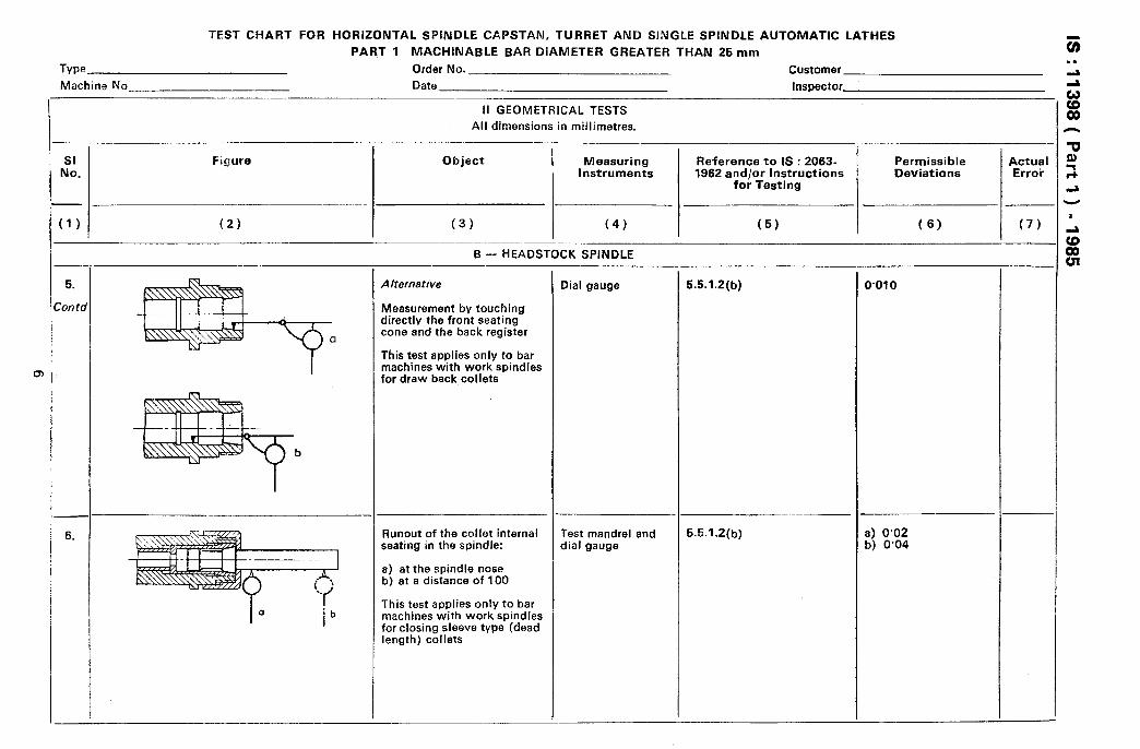
-I Runout of the collet internal seating in the spindle:
a) at the spindle nose
b) at a distance of 100
Dial gauge and test mandrel
Test mandrel and dial gauge
Range 1 :
0’01
Range 2 :
0’15
Range 1:
a) 0’01 b) 0’02
Range 2 :
a) 0.015 b) 0’03
a) 0.015 b) 0.030
.
____ ____ _ C- CROSS SLIDE BASE
Squareness of I he transverse Dial gauge and fiat 5.4.2.3 and 3.2.2 0’02/300 movement of the cross slide disc or straight to the spindle axis edge Mount the dial gauge on the Direction of deviation
cross slide cc >90” This test is applicable to combination turret lathes only
Note - For chucking machines only, the practical test at SI No. 2 may be used as an alternative to this test.
I
8. Parallelism of the longitudinal Dial gauge and 5.3.2.2(a) a) 0’005 movement of the intermediate test mandrel for a measuring carriage to the spindle axis: Mount the dial gauge on the length of 100 (free
cross slide end of the mandrel a) in a horizontal plane forwards only) b) in a vertical plane
b) 0’007 for a measuring length of 100 (free end of the mandrel upwards only)
D -TURRET
Parallelism of turret move- Dial gauge and 5.3.2.2(b) a) 0’02 for a measur- ment on the bed to the test mandrel ing length of 300 spindle axis: Mount the dial gauge on the
turret a) in a horizontal plane
b) 0’02 for a measur- ing length of 300
b) in a vertical plane (upwards only)
This test applies only to Note - The permissi- turret lathes ble deviation remains
0’02 for single spindle automatic lathes with a stroke less than 300.
-
a
Type
Machine No.
TEST CHART FOR HORIZONTAL SPINDLE CAPSTAN, TURRET AND SINGLE SPINDLE AUTOMATIC LATHES
PART 1 MACHINABLE BAR DIAMETER GREATER THAN 25 mm
Order No. Customer
Date __ Inspector _____~~_.~ __ _____._. ____. __.__ ___.___.
II GEOMETRICAL TESTS
All dimensions in millimetres. ___
SI JO.
Figure Object !
Measuring Reference to IS : 2063- Perrttissible Actual instruments , 1962 arid/or Instructions Deviations Error
for Testing
,-
1) (2) (3) (4) (5) (6) (7) _
D - TURRET
10.
CLAMPING
b
-
I s S
S
c
t
1 c
-
‘arallelism of the work spindle axis to the turret top ilide movement of the capstan ;lide:
I) in a horizontal plane i) in a vertical plane
rhis test applies only to :apStin lathes
‘arallelism of the turret bores Nith the turret movement:
3) in a horizontal plane 3) in a vertical plane
rhis test does not apply to nachines with a turret con- ‘iguration type B or to those Nithout tool shank clamping ‘acilities
Dial gauge and test mandrel
Dial gauge and test mandrel
5.3,2.2(b)
Mount the dial Qauge on the turret. The relative positions of the turret top slide and the capstan slide shall be speci- fied by the manufacturer
6.3.2.2(b)
The test mandrel shall not be clamped in the turret but shall be a tight fit. Where thd turret bores are relieved, the test mandrel shall be lightly clamped using the locking mechanism
The test shall be repeated for each turret bore
a) 0.015 for a measur- ing length of 1 SO.
b) 0’02 for a measur- ing length of 150 (up-ward only)
a) and b) 0’02 for 300
f
Alignment of the workspindlt axes with turret bore axes:
a) in a horizontal plane b) in a vertical plane
Alternative Checking by direct measure- ment of the turret bores. This test does not apply to machines with a turret con- figuration Type B
Squareness of the turret faces to the work spindle
Dial gauge in rigid spindle nose
axis: mounting
a) in a horizontal p!ane b) in a vertical plane
This test does not apply to machines with turret con- figuration Types B and C
Alignment of turret recess axes with the work spindle axis:
a) in a horizontal ljlane b) in a vertical plane
Dial gauge (lever type) in rigid spindle nose moun- ting, and as close as possible to the spindle nose
This test applies only to machines with turret con- figuration Type A
Dial gauge in rigid spindle mounting with or without test mandrel
-_
-‘_
5.3.2.2 The dial gauge shall be at two positions, one of which shall be as close as possible to the turret face. The test mandrel shall not be clamped in the turret but must be a tight fit. Where turret bores are relieved, the test mandrel shall be lightly clamped using the locking mechanism
The test shall be repeated for each turret bore
Note - In case test mandrel is used, the length over which the measurement is taken shall be specified by the manufacturer.
5.4.1.1 and 5.4.1.1(b)(3)
Mount the dial gauge as close as possible to the spindle nose
Repeat the test for each turret face
5.3.4.2
The turret shall be in its forward position or as near to the spindle as possible, Repeat the test for each turret recess
--
I
_ -
_
a) and b)
Range I
0.015
Range 2
0.025
a) and b) 0’015/100
a) and b)
Range 1
0’015
Range 2
0’025
Type
Machine No.
TEST CHART FOR HORIZONTAL SPINDLE CAPSTAN, TURRET AND SINGLE SPINDLE AUTOMATIC LATHES
PART 1 MACHINABLE BAd DIAMETER GdEATER THAN 25 mm
Order No. Customer
Date Inspector _____
II GEOMETRICAL TESTS All dimensions in millimetres.
h
Permissible
I I
Actuiil Deviations
;y” Error T
-
_ ___~
SI No.
Figure Object
(4) (2) (3)
Measuring Instruments
Reference to IS : 2063- 1962 and/or Instructions
for Testing
(4) (5) (6) I (7)
D - TURRET - --._
5.3.2.2(a)
Repeat the test, made over the whole cutting stroke, for each turret face, iri the indexing position
15.
16.
Parallelism of thb turret faces with the turret movement
This t&t applies only to machine with turret con- figuration Type B
Dial gauge and special device if specified by the manufacturer
0’015 for any measuring length of 100
r -.
5.3.2.2(a)
.-
Repeat the test. made over the whole cutting stroke. for each turret face, in the indexing position
Parallelism of turret tool holder location slot ( or tenon) to the turret move- ment
Parallelism of the turret tool holder location slot ( tenon )
This test abplies only to machines with turret con- figuratidn Type 6
Dial gauge and special control device if specificed by the manufacturer
0’015 for any measuring length of 100
Type
Allachine No.
TEST CHART FOR HbRlZONTAL SPINDLE CAPSTAN, TURRET AND SINGLE SPINDLE AUTOMATIC LATHES
PART 1 MACHINABLE BAR DIAMETER GREATER THAN 25 mm
Order No. Customer
Date Inspector
II GEOMETRICAL TESTS
All dimensions in millimetres.
SI No.
-
:I)
Figure Object Measuring Instruments
Reference to IS : 2063- 1962 and/or Instructions
for Testing
Permissible Deviations
/ I
I /
I (2) I (3)
I (4)
I (5) I (6)
Actual Error
(7)
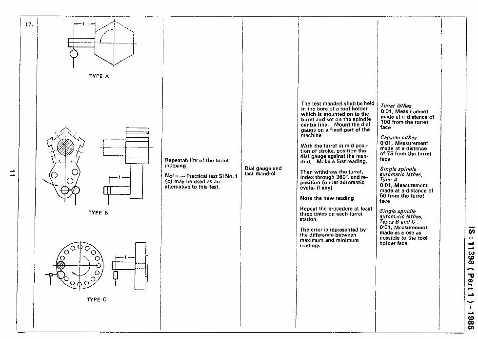
18.
is.
-
-1.
t 25 mm
+ + __‘______---i
+: + :+
,_________-’
+ -I- +
25mm - 3 tc /
On some machines the steady bar is fixed to the head stock; on others, it is fixed to the turret.
b
Repeatability of indexing of the square turret on cross slide:
a) b)
-
/
_-
I
I
-
in a radial plane alternative in an axial plane
Parallelism of the steady bar with the turret movement:
a) in a horizontal plane b) in a vertical plane
D -TURRET
-
Dial gauge and test bar
Dial gauge 5.3.2.2(b)
-
I
- _
614.2 and 6.4.2.1 The test bar shall be mounted in the square turret to simulate a tool. Mount the dial gauge on a fixed part of the machine Take the first reading Then index the turret through 360” Note the new reading Repeat at least three times for each turret face The error is shown by the difference between maximum and minimum readings Note - For (a) and (b) the dial gauge shall be set in the plane of the face of the turret.
a) and b) 0’02 at a distance o f 25 from turret face.
a) and b) 0’02 for each measur- ring length of 300
TEST CHART FOR HORIZONTAL SPINDLE CAPSTAN, TURRET Al\iD SINGLE SPINDLE AUTOMATIC LATHES
PART 1 MACHINABLE BAR DIAMETER GREATER THAN 25 mm
Type __.. ___ ..__ ~__ .._~~. Order No. Customer
Machine No. _--- Date inspector -..- _. ~___ ___- -
i
SI rho:
(1)
1.
-___- _ ____-..-.~~---
Figure
(2) --- -.-.-.
II= 10 I, = 40
h
For bar machines: D == 0’8 x nominal bar capacity L 0’8 jc maximum cutting stroke
2’5 x nominal bar capzity. Retain for 1 the smaller of these values up to a maximum of 150mm
For chucking machices: D = 0’3 x nominal chuck diameter (up to a maximum value of 150)
L r 0’8 xlmaximum cutting stroke V<k e:- or
0’8 x nominal chuck diameter. Retain for L the smaller of these values, upl to a maximum value of 200
Note - Where the value of L exceeds 100, additional intermediate bands with a maximum spacing of 40 shall be machined.
I I
,
I
I I I
I
I
1 ,
I
1
,
I
III PRACTICAL TESTS
All dimensions in millimetres.
Nature of Test and Cutting Conditions
..-___-
(3)
Turning of a cylindrical test piece held in or on the spindle nose from the turret with a jingle point tool mounted on 3ne station of the turret and 3n the cross slide. For test (C) repeatability, at least 3 test pieces shall be machined. Turret shall be indexed through 60” before machining a new test piece
As an alternative, practical test at SI No. 1 (c) may be carried out on stub test oieces with a minimum length of cut 10
Test piece (or pieces) material together wiih type and form of tool, fbed, depth of cut and cutting speed shall be specified by the manufacturer
This test applies to both bar end chucking machihes
Checks to be Applied
(4)
a) Circularity Variation in radius at the location end of the test piece for at leasi 4 readings
b) Consistency bf the machined diameter:
This test applies to turrets with an axis parallel or perpendi- cular to the sbindle axis
The consistency of the machined diameters is the variation between the diameters of each end of each test piece measured in a single axial plane
Three or four measure- ments shall be made along the length of the test piece, dependent on its length
c) Repeatability Variation between dia- meters of the location end of the test pieces, measured in a single plane marked on the spindle nose
--
/
-
--
i
Measur- ing Instru-
ments
(5) _._.__-
Micro- meter and roundness ineasuring instru- ments
Reference to IS : 2063-1662
and/or Instruc- :ions for Testing
(6)
3.1, 3.2,4.1, 4.1.1, 4.1.2, 4.1.3, 4.2 and 4.2.1
Permissible Deviations
(7)
a) 0’005
b)
1) for crbss slides:
0’02 per 100
2) for turrets: 0’02 per 100
3) for capstan: 0’025 per 100
If more than two bands on test piece, then permissible variation between adjacent bands shall be:
0’01
c) 1 1 for turret lathes
and single spindle auto- matic lathes: 0’025
2) For capstan lathes: 0.035
Actual Error
(8)
Maximum length of thread cut 150. Diameter of test piece as close as possible to that of the lead screw. Thread pitch half that of the lead screw
Threading according to IS : 4218 ‘IS0 metric screw thread’, a cylindrical test piece with a single point tool
The start of the screw thread is taken from any point on the lead screw
This test applies only to machine’s with lead screw control
Accuracy of the pitch Special 3.1, 32.2, 4.1.1, instru- 4.1.2, 4.1.3,
Cumulative pitch
4.2.1, S.l.l.,4. error 0’02 for any
ments of measured length tested 6.2, 6.2.0. 6.2.1, of 60 precision 6.2.2 and 6.2.3
The screw thread shall be clean without flats or waviness
. IS : 11398 ( Part 1 ) - 1985
EXPLANATORY NOTE
This standard is generally based on IS0 6155/1-l 981 ‘Acceptance condition for horizontal spindle capstan, turret and single spindle automatic lathes - Testing of accuracy : Part I Machinable bar, diameter greater than 25 mm’, issued by the International Organization for Standardization (ISO).
In this standard, permissible deviation values have been specified for geometrical test Sl No, 7 and 11 based on India’s comments on fSO/DlS 6155/l, which differ from the corresponding values given in published IS0 6155/l -1981. The corresponding values given in IS0 6155/l -1981 are:
1) O’Ol/lOO; and
2) for (a) and (b) 0’015 for measuring length of 100 respectively.
Separate standard on single spindle automatic lathes having machinable bar diameters less than 25 mm shall be formulated after the IS0 standard on this subject is published.
16 Printed at Pcintrade. New Delhi. India
AMENDMENT NO.1 OCTOBER 1988
TO
IS :11390(Part l)-1985 'TEST CtlART r‘C)R IIIJIfI 7Of11AL SPINDLE CAPSTAN, TURRET AND SINGLE SI'INULE
AUTOMATIC LATHES
PART 1 HACIiIfWLE UAR DIAMTERS CIGYAICR IIIAIJ %5 IIIII
(Pctgs 5, Test Sl NO. 3, CO1 6, range 2) - Substitute '0.015' for '0.15'.
(Page 13, Test SZ Ao. I, co1 3, pam 2, Ins t line) - Substitute the following for the existing line:
'Turret shall be indexed through 360° before rnachirlin~; a new test piece.'
(EDC 11)
-
Reprography Unit, BIS, New Delhi, India
.
c
.
AMENDMENT NO. 2 AUGUST 1996 TO
IS 11398 ( Part 1) : 1985 TEST CHART FOR HORIZONTAL SPINDLE CAPSTAN, TURRET AND
SINGLE SPINDLE AUTOMATIC LATHES
PART 1 MACHINABLE BAR DIAMETERS GREATER THAN 25 mm
Substitute ‘IS 2063 : 19WISO 230/l : 1986 Acceptance code for machine tools - Geometric accuracy of machines operating under no-load or finishing conditions (first revision )’ for ‘IS 2063 : 1962 Code for testing machine tools’ wherever it occurs in the standard.