Disclosure to Promote the Right To Information Whereas the Parliament of India has set out to provide a practical regime of right to information for citizens to secure access to information under the control of public authorities, in order to promote transparency and accountability in the working of every public authority, and whereas the attached publication of the Bureau of Indian Standards is of particular interest to the public, particularly disadvantaged communities and those engaged in the pursuit of education and knowledge, the attached public safety standard is made available to promote the timely dissemination of this information in an accurate manner to the public. इंटरनेट मानक “!ान $ एक न’ भारत का +नम-ण” Satyanarayan Gangaram Pitroda “Invent a New India Using Knowledge” “प0रा1 को छोड न’ 5 तरफ” Jawaharlal Nehru “Step Out From the Old to the New” “जान1 का अ+धकार, जी1 का अ+धकार” Mazdoor Kisan Shakti Sangathan “The Right to Information, The Right to Live” “!ान एक ऐसा खजाना > जो कभी च0राया नहB जा सकता ह ै” Bhartṛhari—Nītiśatakam “Knowledge is such a treasure which cannot be stolen” IS 15729 (2007): Natural gas pressure regulating and metering terminal - Code of practice [MED 17: Chemical Engineering Plants and Related Equipment]
Transcript
Disclosure to Promote the Right To Information
Whereas the Parliament of India has set out to provide a practical regime of right to information for citizens to secure access to information under the control of public authorities, in order to promote transparency and accountability in the working of every public authority, and whereas the attached publication of the Bureau of Indian Standards is of particular interest to the public, particularly disadvantaged communities and those engaged in the pursuit of education and knowledge, the attached public safety standard is made available to promote the timely dissemination of this information in an accurate manner to the public.
इंटरनेट मानक
“!ान $ एक न' भारत का +नम-ण”Satyanarayan Gangaram Pitroda
“Invent a New India Using Knowledge”
“प0रा1 को छोड न' 5 तरफ”Jawaharlal Nehru
“Step Out From the Old to the New”
“जान1 का अ+धकार, जी1 का अ+धकार”Mazdoor Kisan Shakti Sangathan
“The Right to Information, The Right to Live”
“!ान एक ऐसा खजाना > जो कभी च0राया नहB जा सकता है”Bhartṛhari—Nītiśatakam
“Knowledge is such a treasure which cannot be stolen”
“Invent a New India Using Knowledge”
है”ह”ह
IS 15729 (2007): Natural gas pressure regulating andmetering terminal - Code of practice [MED 17: ChemicalEngineering Plants and Related Equipment]
IS 15729:2007
Indian Standard
NATURAL GAS PRESSUREREGULATING AND METERING TERMINAL —
CODE OF PRACTICE
ICS 75.200
(3 BIS 2007
BUREAU OF INDIAN STANDARDSMANAK BHAVAN, 9 BAHADUR SHAH ZAFAR MARG
NEW DELHI 110002
Febt-uary 2007 Price Group 8
Chemical Engineering Plants and Related Equipment Sectional Committee, ME 17
FOREWORD
This Code was adopted by the Bureau of Indian Standards, after the draft finalized by the Chemical EngineeringPlants and Related Equipment Sectional Committee had been approved by the Mechanical Engineering DivisionCouncil.
The transportation and distribution of natural gas through cross-country pipelines are the major business of the oil
and gas companies. It was felt that pipeline supplies were rapidly being laid to feed distribution systems forvarious users and that there was a need for a document embodying recommendations to ensure the utmost reliabilityand continuity of supply at pressures that are acceptable to and safe for the downstream pipeline or distributionsystem. Assistance has been derived from lGE/TD/ 13 ‘Pressure regulating installations for transmission anddistribution systems’ covering installation with inlet pressures between 0.7 to 10.0 MPa.
Considering the importance of metering, regulation, data acquisition and safety of gas transmission, this Code forregulating stations has been prepared.
This Code does not restrict the use of new and better techniques developed and proved in due course of time.
The composition of the Committee responsible for the formulation of this standard is given in Annex D.
For the purpose of deciding whether a particular requirement of this standard is complied with, the final value,observed or calculated, expressing the result of a test or analysis, shall be rounded off in accordance with[S 2:1960 ‘RuIes for rounding off numerical values (revised)’. The number of significant places retained in therounded off value should be same as that of the specified value in this standard.
1S 15729:2007
Indian Standard
NATURAL GAS PRESSUREREGULATING AND METERING TERMINAL —
CODE OF PRACTICE
1 SCOPE
This Code covers the commissioning, operation andmaintenance and safety aspects of natural gas pressureregulating and metering terminal.
This standard shall be used in conjunction with1S 15677.
2 REFERENCES
The standards listed in Annex A contain provisions
which, through reference in this text, constitute
provisions of this standard. At the time of publication,the editions indicated were valid. All standards aresubject to revision and parties to agreements based onthis standard are encouraged to investigate thepossibility of applying the most recent editions of thestandards indicated at Annex A.
3 TERMINOLOGY
3.1 Cathodic Protection (CP) — A method ofprotecting a metallic pipeline/structure from corrosion
by making it a cathode so that direct current flows onto the pipeline/structure from the surroundingelectrolytic environment.
3.2 CP Related Terminology
3.2.1 lt~sula~ing Flanges — Flanges which permitmechanical continuity but break the electricalcontinuity.
3.2.2 Isola?illg Joint — Electrically insulatingcomponent such as monoblock insulating joint,insulating flange, isolating coupling, etc, insertedbetween two lengths of pipeline/structure to preventelectrical continuity between them.
3.3 Closing Time — The time taken by a slam-shutvalve between commencing and completing the closingaction of its internal valve element.
3.4 Creep (as Applied to Gas Control Equipment) —The minor leakage volume of gas which a regulator orother control unit may be unable to contain in itsnominally closed state.
3.5 Creep (as Applied to Polymeric Material) — Thephenomenon of growth or displacement of the materialresulting from applied stress, aging or other factors.
3.6 Dead Time — The time taken by a slam-shut valveto sense a pressure signal.
3.7 Gas
3.7.1 First Family Gas — Gas of Wobbe number 24.4to 28.8 MJ/m3 commonly known as ‘town gas’.
3.7.2 Second Family Gas — Gas of Wobbe number48.2 to 53.2 MJ/m3 commonly known as ‘natural gas’.
3.8 Holiday — A flaw in the protective coating of a
pipe or component which may expose the underlying
surface.
3.9 Impulse — The pressure sensed at the selectedpoint in the gas stream.
3.10 Lower Flammable Limit (L~) — Theconcentralation of flammable gas, vapour of mist inair above which combustion can be sustained.
This term may be considered equivalent to the term‘Lower Explosive Limit’ (LEL).
3.11 Non-destructive Testing (NDT) — Testing ofpipework and components by methods, such as
radiography, ultrasonic and magnetic crack detectionetc, that are not destructive.
3.12 Pig — A device which can be propelled througha pipeline by fluid pressure, used for various purposes,for example, cleaning, swabbing, inspection, etc.
3.13 Pig Trap — A vessel connected to the end of asection of pipeline, having a breech loading/unloadingarrangement for launching and receiving pigs.
3.14 Pressure Related Terminology
3.14.1 Design Pressure — The design pressure shouldbe higher than the maximum pressure to which thesystem could be subjected during operation. The valueselected as the design pressure should take account ofany foreseeable overpressure condition, particularlywhere this is coincident with adverse temperature and/or fatigue conditions and of the performance of anyoverpressure protection devices in the system.
3.14.2 Maximum Working Pressure (MWP) — Themaximum pressure to which a pipe or component maybe subjected in normal operation.
1
IS 15729:2007
3.14.3 Z'.\r/'r[.s.~/{rc-Thep ressuret o\$rllichcopponentsor complete installations aresubjected for acceptancepurposes,
3.15 ReguIato rRelate dTerminology
3.15.1 Rc,qr{[[{tor- A device whose function is to
automatically control pressure or volume flow at aselected point in a gas stream.
3.15.2 Pr~'.s.sllr('Rc'gul(~tor- Aregulatorwhich nlaintainsa preset constant pressure at a point on its outlet.
regulator which maintains a preset constant rate ofvolume flow irrespective ofinlet pressures.
3.15.4 Mo}]itor/Active Regulation -Anarrangementof two regulators in series whose pressure settings arestepped so as to allow one regulator (active) normallyto control the outlet pressure and the other (monitor)
to assutme control in the event of failure of the activeunit towards the open position.
3.15.5 Pilor Control — A subsidiary regulatingImechanism that generally employs the pressureupstream of the main regulator orother control unit
as a power source to exert control over the mainregulator.
3.15.6 Size ofu Regulator — Size of the regulator isdefined as the nominal diameter of the regulator’s inletconnection.
3.15.7 Capacity of a Regulator — The maximumvolume flow which a regulator will pass at given inletand outlet pressure under specific gas measurementconditions for which the regulator is designed whilstmaintaining stable control of that flow.
3.15.8 Ratlgeubility of a Regulator — The ratio of themaximum capacity of regulator to the minimumcapacity. The maximum capacity can usually beobtained from the manufacturer’s catalogue, makingdue allowance for the specific gravity of the gas handledand the pressure recovery appropriate to the particularinstallation. The minimum capacity is that volume flow
down to which the regulator is designed to maintainstable control.
3.15.9 Rcpe[ttobility of Actuation — The limits ofdeviation from pressure set point within which a slam-shut valve is able, repeatedly without failure, to actuateclosure from its normally open state.
3.1 S.10 /J\tt[//~~ic fc~forfnat~ce — The transientbehaviour of a regulator in Controlling pressure or flowfollowing deviation from set-point.
3.15.11 Trim — A term embracing the internal flowcontrol elements within the body of a regulator, valveor other control unit.
3.15.12 Lock-Up — The act of closure of a regulatorwhen gas demand falls to zero.
3.15.13 Wicking — A term used to describe the escape
of gas within a pressurized, fabric-reinforced rubberdiaphragm when the leakage path is along the fabricinterstices.
3.15.14 Relief Valve (Relief Regulator) — A valve orregulator incorporated to protect a system, or acomponent part thereof, against excessive pressure. Itsfunction is to vent, usually to atmosphere, when a pre-
determined pressure is attained.
3.16 Slam-Shut Valve — A valve-that is designed to
close quickly in the event of an abnormal (usuallyexcess) pressure being detected at a selected point in agas stream.
3.17 Thermowell — A metal pocket protruding intothe gas stream to house a temperature-measuring device.
4 PLANNING, LAYOUT AND SECURITY
Any natural gas pressure regulating and meteringterminal must be designed, located, constructed and
operated taking into consideration the safety andenvironmental requirements of applicable legislation.
4.1 Planning
Consideration should be given to the layout and otheruses of the station, for example, gas storage, the need
for security of the station and any housing for the naturalgas pressure regulating and metering.
Consideration should be given to the possibility offlooding and, in the case of an underground installation,the Iikel ihood of a rising water table.
4.2 Station Location
When selecting the location for a natural gas pressureregulating and metering, care should be taken to avoidthe following:
a)
b)
c)
d)
Proximity to residential properties or areas thatmay be subject to residential development;
Proximity to tall buildings where eddy currents
around the building may cause problems withgas dispersal;
Positioning the natural gas pressure regulatingand metering beneath or close to overheadpower lines; and
Vulnerable sites where traffic accidents, etc,
could result in damage to the natural gaspressure regulating and metering.
4.3 Station Layout
4.3.1 The area of the station should be adequate toaccommodate the equipment and provide access for
2
IS 15729:2007
maintenance purposes andlor the location of emergencyfacilities, for example, fire extinguishers.
NOTE — It is desirableto providehard access up to and withinthe station to accommodate maintenance and emergency servicevehicles.
4.3.2 An emergency exit should be provided, ifappropriate.
4.3.3 Vulnerable pipework or equipment should beprotected, where necessary.
4.3.4 Any hazardous area should be taken into accountwhen determining the station boundary.
4.3.5 The combustion air intake of arty gas heater or otherburner equipment should be located so as to minimize
any hazard arising from any source of gas leakage oremission, for example, from a filter, relief valve vent, etc.
4.3.6 Consideration should be given to:
a) access for pigging operation and equipment,
b) minimizing noise,
c) access for maintenance activities,
d) excess for fire fighting, and
e) gas detection.
NOTE — Where gas is not odorized, enhancedarrangementsmaybeneeded,such as prominent noticesand/or additional detection equipment.
4.4 Station Security
4.4.1 Any station should be secured against entry byunauthorized persons.
4.4.2 If a station security fence is used, equipmentshould be sited at a sufficient distance from the fenceto prevent interference from outside.
4.4.3 Consideration should be given to the provisionof a locking device for valves, including auxiliary
valves located external to a natural gas pressure
regulating and metering housing.
4.4.4 Consideration should be given to installingintruder detection devices.
4.4.5 Where the presence of vehicular tratlic couldcause a hazard, the use of safety barriers should beconsidered.
4.4.6 Prominent signs should be displayed, prohibitingsmoking and other ignition sources.
4.4.7 A permanent notice should be displayed clearly,showing an emergency telephone number which maybe used by the public or others.
5 COMPONENTS OF NATURAL GASDESI?ATCH TERMINAL
The natural gas terminal shall generally include:
a) Two or more high pressure inlet filters withsuitable valves and connections to permitdesign throughput to be maintained with oneunit out of action.
b) Means to avoid the entrapment of liquids inthe gas entering a pressure regulator and ifnecessary, suitabIe provision made for theirremoval.
It is particularly important that the gas supplyto valve control instruments should be tlee ofliquids and dust and suitable filters/separatorsshall be installed as appropriate.
c) Two or more streams of pressure regulators,
each stream to contain at least one pressureregulator. For critical installation,consideration may be given for one monitorand one active regulator in each stream. Wherethe installation is not a big gas despatchterminal, consideration may be given to the
provision of a single stream of pressureregulators only.
d) Upstream slam-shut valves shall be fitted onall streams of pressure regulators.
e) Installations should be designed to withstandmaximum inlet pressure conditions to be atmetering station. Where this is not reasonablypracticable, the design should include inter-state relief valves in each stream where morethan one stage, if pressure reduction isinvolved. Such relief valves should be at leastof sufficient capacity to offset the effects of
gas passing due to failure of regulators to‘lock-up’ at times of no flow.
Protection may also be afforded by providingan auxiliary trip switch for the slam-shut valvereferred to in (d) above.
f) In certain circumstances failure of a pressurereduction installation to ‘lock-up’ at periodsof low flow may cause the normal workingpressure of the system into which it deliversto be exceeded, the use of a relief valve andvent of sufficient capacity to offset thisfailure to lock-up maybe considered, if theoperation of the slam-shut system isunacceptable.
g) It is necessary to consider whether pre-heating of the gas is required to avoidunacceptably low temperature in the
downstream pipe network and auxiliarysystems due to pressure reduction. If heatersare installed then they shall be controlled insuch a way as to avoid high gas temperaturewhich may damage any seal, diaphragm orvalve seat in equipments like regulators,meters, relief valves, etc.
3
IS 15729:2007
To meet the above requirement the main componentsof natural gas terminals are as follows:
a)
b)
c)
d)
e)
f)
g)h)
j)k)
Gas filtration system;
Gas heating system;
Pressure regulators;
Pressure relief valves, vent and drains;
Valves and actuators;
Slam shut valves;
Thermowell;
Meter and associated piping;
Electrical system; and
Supervisory control and data acquisitionsystem.
NOTE — The applicable aspects of EN 12186 maybe usedas reference for functional requirements of gas pressureregulating stations and their operation, maintenance and safetyrecommendations.
5.1 Gas Filtration System
Filters, scrubbers and separators or composite units
should be installed on the inlet of gas Despatch terminalto clean the gas to a standard required for satisfactoryoperation of the downstream equipments.
Certain filter elements shall withstand high differentialpressures which could be sufilcient to shut off the
supply of gas through the installation. In some casessuch conditions could not be tolerated and alternative
types of fi Iters with internal components designed tocollapse and/or relieve high differential pressures
may be preferred; the selection of downstreamequipment should therefore take account of the
choice made.
The filter shall be so designed that the desired degreeof filtration is achieved in the normal operatingconditions. Maximum pressure loss across the inleti
outlet flanges of filter shall not be more than thatspecified in process parameters of product data sheet.
The filter element shall be suitable for any reverse flow
of gas. Filter design shall be such that only the elementitself shall require replacement when blocked/chocked.
The end closure should be such that filter element couldI-seaccessed.
5.1.1 The design of the filter assembly shall take intoaccount the following:
a) Ease of replacement of basket (for examplethe baskets should be bolted to a support ring).
b) If welded to the pressure shell, the basketsupport ring shall be of such a design as toavoid shrinkage stress (for example, segmentconstruction), with a suitable gasketarrangement to prevent bypass.
c)
d)
5.1.1.1
Horizontally positioned baskets shall beadequately supported. Baskets of cantileverdesign are not acceptable.
All baskets/elements shall be designed towithstand the effects of any vibration underall operating conditions.
The recommended differential pressure beforecleaning or changing and the maximum differentialpressure which the element can withstand beforecollapse shall be specified by the filter manufacturerin the data sheet.
5.1.1.2 The filter body shall be provided with supportswhen specified in the data sheet. In case saddle typesupports are provided, these shall be either welded tothe body or of the loose clamp type. Supports shall
make designed displacement in either direction inaddition to fill axial movement to allow for movementof the pipework.
5.1.1.3 Vent and drain connections shall be providedon the body of the filter. Unless otherwise specified,different pressure tappings shall also be provided onthe body.
5.1.1.4 All”flangesshall be fitted so that their bolt holesare off the vertical and horizontal centre line.
5.1.2 Mechanical Design
5.1.2.1 The design pressure for the filter shall be asdesired by the buyer and same shall be stated in thedata sheet.
5.1.2.2 For the ambient temperature range of –20°to 50”C, the lower design temperature for thedetermination of impact properties of metallic materialsshall be taken as –1 O°C. For other operating temperatureranges, the lower design temperature shall be as statedby the buyer.
5.1.2.3 The design pressure shall be such that duringthe hydrostatic pressure test, the design stress shall notexceed 90 percent of the specified yield stress.
5.1.3 Manufacturing, Inspection and Tests
5.1.3.1 All flanges left for connection by others shallbe square to the centre line of the vessel within 0.25 mti100 mm of flange outside diameter.
5.1.3.2 The peripheries of the flanges shall be machinedwithin the following tolerances:
a) Up to and including 200 mmnominal size +0.5 mm
b) Greater than 200 mmnominal size +1.Omm
5.1.3.3 The completed vessel, including the end closure,shall be pressure tested hydrostatically.
4
5.2 Gas Heating System
Due to reduction in pressure across the control valve/
regulator, the temperature of gas reduces, it may benecessary to Ynstall pre-heaters to avoid unacceptable
low temperatures on the outlet of pressure reductionequipment. Generally it is not necessary to provide pre-
heater where differential pressure across the installation
is less than 1.5 Mpa.
In establishing a requirement for the provision of pre-
heating of gas, the aspects to be seen areas under.
The ability of the downstream pipe material to retainsat isfactory physical characteristics at any reduced
temperature of operation.
The possibilities of hydrate or liquid formation whichmay inftuence the operation of the equipments.
The possibility of frost formation due to Iiozen ground
around buried outlet pipe.
The effective operation of any gas conditioning process.
The number of heaters and their capacity should be
determined having regard to the probability of failure
of unit occurring simultaneously with a period ofextreme demand. If this possibility is low then the
provision of standby heater capacity to meet theextreme condition may not be necessary.
Consideration should be given to the reliability of theheating system in operation, taking into account its
dependence of other services. It maybe necessary to
provide standby water and electricity supplies where
continuous operation under all fault conditions is
essential.
Any polymeric and elastomeric materials used in theinstallation should be capable of withstanding the
maximum temperature that the preheat source canattain. To avoid exceeding the safe operating
temperature of these materials in meters or regulatorvalve seats it may well be necessary to limit themaximum temperature of the preheat source.
The heater installation should be equipped with a meter
and control system which minimizes the energyconsumed by the preheater. This is normally achieved
by carefully sensing the temperature of the gas
downstream of the regulators to control the operationof heaters.
The chosen set-point should be as low as possibleand this equipment and control system should bedesigned to maintain a minimum variation from thisset-point.
The determination of the heat input required should be
carefully considered to meet a particular duty. The
IS 15729:2007
complete calculation shall be undertaken having regardto the composition of the gas to be ,heated and the
influence of pressure on the specific heats of the various
constituents.
Heating of the gas maybe achieved by the use of heaterunits located in the installation on the inlet side of theregulators.
The following forms of gas heaters maybe used:
a) Water bath heaters — These consist of tubularelements, carrying the gas, immersed in awater bath, which is maintained at the requiredconstant temperature by the use of a burnerfitted with standard controls and safety devicesto maintain the desired exit temperature in thegas stream.
b) Indirect heaters — These consist of tube-in-shell heat exchangers located in the gas stream,heated by steam from an external source, orby hot water circulated from an adjacent boiler
or modular boiler unit.
The pressure-containing parts of all heating installations
subject to gas pressure shall be constructed and testedin accordance with the requirements of IS 2825. Dueallowance for corrosion shall be made where it isnecessary.
5.3 Pressure Regulators
5.3.1 Design
Regulator bodies, diaphragm chambers and boltingshall be designed to withstand the maximum pressureand temperature variations under fault conditions. Partsof the regulator normally subject to outlet pressure only
should where practicable, also be designed to the samestandard unless provided with integral pressure relief
of adequate capacity.
For inlet pressure up to 10 MPa and size up to DN 400,pressure regulators, the applicable aspects of EN 334may be used. as reference for the constructional,functional and testing requirements.
Regulators should be sized on the basis of maximumdesign flow rate coefficient with demand at minimumdifferential pressure and inlet and outlet pressure rangecapability. The type selected should have a dynamicperformance compatible with the characteristics of thesystem to be supplied; taking into account anyassociated metering arrangements.
Wherever it is known that stream capacity is likely tochange, consideration should be given to the installationof regulators with adjustable rangeability.
It is desirable that a port opening indicator and scalebe incorporated in all main regulators.
5
IS 15729:2007
A schematic line diagram of natural gas pressureregulating andmetering terminal isshown in Fig. 1.
5.3.2 Pressure Testing
Hydrostatic testing shall be carried out at the pressure
shown in Table 1. The test pressure shall be maintainedfor the test duration shown in Table 2 without anyleakage.
Manufacturer of regulator shall provide the hydrostaticand pneumatic test certificates.
Table 1 Hydrostatic Test Pressure
(Clause 5.3.2)
Material Pressure Rating of HydrostaticRegulator Body Test Pressure
(1) (2) (3)
Material shall be 2.0 MPa (Class 150) 1,5 times of
as specified in the 5.0 MPa (Class 300) rated pressure
purchase order 10.0 MPa (Class 600)
NOTE— 1 bar= 1 OOOmbar= l@ N/m2= 10’Pa=O.10MPa.
f-a
INLET\ >
\/
la
VENT
4 1 1’
“1!“’i:+OVER-RIDE -
Pc
Pc PC H
?2
OUTLET OVER-RIDE-
I I I 1
SYMBOLS USED IN THE SCHEMATIC LINE DIAGRAM
21-H
HEATER SLUM-SHUT VALVE
FILTER + PRESSURE OR VOLUMETRICREGULATOR
+z-
NORMALLY OPENED VALVE * PREsjsURE cONTROL@
4EMERGENCY OR
PRESSURE SAFETY VALVE SAFETY ACTING oPz
FIG. 1 TYPICAL NATURAL GAS PRESSUREREGULATINGAND METERINGTERMINALWITH
Two STAGE PRESSUREREDUCTIONAND MONITOR OVER-RIDE
6
IS 15729:2007
Table2 Duration of Hydrostatic Test
(Cluuse 5.3.2)
SI Body Size Minimum Time Duration of TestNo. nun min
(1) (2) (3)
i) Up to 80 2ii) 100to 150 3iii) 200 to 250 5iv) 300 to 450 7v) 500 and above 8
5.3.3 Performance
Adequate test or desi~n data on capacity, rangeability,lock-up, minimum and maximum operating pressuredifferentials, dynamic performance characteristic andpredicted noise level emission should be obtainedfrom the manufacturer in order to determine theperformance of regulators under various operatingconditions. Results of any tests carried out by themanufacturer to determine operational performance
and thereby confirm these design data should also bemade available.
In order to derive the capacity of a regulator withreduced or modified trim, the manufacturer shouldprovide on request all relevant data which is reasonablyobtainable.
5.3.4 El[{sto}wric and Poiymeric Components
All flexible elastomer diaphragms used for operating
the gas regulator, its pilot controls and its additionalsafety features should be fabric — reinforced. Theyshould be resistant to delamination and ‘wicking’ under
all working conditions.
Diaphragm assemblies should be designed in such away that the operating differential pressure ratingshould not exceed the maximum working pressuredifferential rating of diaphragm. The burst pressure ofdiaphragm should beat least three times the maximumworking differential pressure.
gaskets regularly subjected to a gas environment shouldbe fabricated from materials that are resistant to anyconstituent of gas under normal or abnormal condition,for example, methanol. Additionally polymericcomponent including so-called ‘engineering plastics’shall be chosen discreetly and only after carefi.d researchof their stress-bearing, ‘creep’ -resisting and gas/moisture absorbing properties,
Elastomeric components including seals should be from
the prescribed tit and perform properly. They should
bear an identification number related to their
manufacturing specification and the date.
5.4 Pressure Relief Valves, Vent and Drains
Provision should be made for venting, purging and
draining all sections of pipe network and equipmentthat may have to be isolated during construction or
maintenance.
Due consideration should be given to the environment
and so far as reasonably practicable to safety.
All relief valves should preferably be fitted upstreamof customers’ premises. Extreme care should be taken
in choosing the location of relief valves so that the
vented gas will not interfere with industrial processesand the chances of ignition are minimized.
To ensure that gas is dispersed safely the vent stackshould discharge vertically. The vent tip should be at
least 3 m above the ground level. The location of a stack
close to features such as cliffs, quarry walk etc, should
be avoided.
A weather cap should be fitted which allows unimpeded
vertical discharge of gas. Weather caps should be
designed as far as reasonably practicable to be non-sparking.
Particular care should be taken to avoid sitting a stacknear to furnaces, gas turbine inlets etc, where dangers
might arise from the ingress of combustible gases.
The securing of diaphragms, sleeves or liners with The capacity of pressure-relief valves and vents shouldregulators and other control units should be designed be designed to limit pressure in the system to the extentin such a way that the damage is avoided which may as specified for various sub-systems. The relief valvecause due to the components overstressing or other shall be capable to pass maximum one percent of theact ions which could unreasonably reduce their effective full stream flow at full fault condition.working life.
Flexible elastomer sleeves and liners which arepositioned directly in the main gas stream and functionas control membranes should be resistant to abrasionand effects of long-term deformation. They should becapable of operating for long periods high differentialpressure and low temperature with undue degradationof performance.
Al I elastomeric and polymeric components including
Relief valves, whether direct-acting or pilot controlledshould be fully automatic in operation.
The outlet of vent should terminate with a weather cap.
The upstream connection of the relief valve should notimpose any restraint on free gas flow.
The vent system should have adequate support and
anchorage to minimize induced stresses in the relief
valve and its associated piping.
7
IS 15729:2007
5.5 Valves and Actuators actuator being transmitted to the valve stops and bodv.
The design and construction of valves shall meet theWherever appropriate the direction of gas-flow shouidbe clearly marked on the valve body.
requirements of ISO 14313.
All valves should be fitted with a device to indicateThe applicable aspects of EN 14382 for inlet pressure
accurately the position of the plug, ball, gate or disc.up to 10 MPa and size up to DN 400, Slam-Shut Valves
Consideration should be given to the need to vent themay be used as reference for the constructional,
body of the valve. Where it is necessary to lubricate afunctional and testing requirements.
valve for continued satisfactory operation seals shouldbe provided to minimize the amount of excesslubricant passing into the gas stream. This is especiallyimportant, if metering is directly associated with theinstallation.
The dimensions of the flanged ends of valves shall meet
the requirements of IS 13159 (Part 1). Requirementsfor preparation of the end of valves to be welded in-line should be specified to the manufacturer.
Valve bodies should be hydrostatically tested under the
cond itions stated in the standard relevant to the typeand pressure rating selected in accordance with 5.3.2
and test certificates provided by the manufacturer.
Hydrostatic and pneumatic seat leakage tests shouldbe applied to all valves under the conditions stated inthe relevant standards.
Care should be taken to ensure the correct matching of
an actuator to a valve both in terms of required torqueand mechanical attachment. The conditions underwhich the valve is required to operate including speed
of action should be specified to the manufacturer.
Where valves are ordered with actuators stem
extensions gear-boxes, etc, the valve manufacturershould be responsible for matching and fitting themand ensuring that each assembly functions correctly.Removal of the actuator should not affect the pressure-tightness of the valve.
Actuators should be fully weatherproof. All electricalequipment should be housed in a flameproof enclosure.Mechanically independent hand-operated drive shouldbe provided as part of any actuator and it should bedesigned that it can be operated easily by a operator/engineer. Interlocks should be provided to prevent localor remote automatic operation whilst the hand-operateddrive is engaged.
5.6 Slam-Shut Valves
The selection of a particular type of slam-shut valve
should take into account calculations to determine amaximum acceptable safe closing time. The factorsinvolved in these calculations shall include:
a) Maximum working pressures,
b) Volume of associated downstream piping,
c) Fail-open characteristics of the regulator(s),
d) Capacities of the relief valves and vents, and
e) Flow rate through the working regulator underfault conditions.
The greatest temporary flow rate and pressureaccumulation in the downstream system shall occur
when a regulator or syste,m of regulators suddenly failsto open while the installation is operating at maximumdifferential pressure. In no case should the temporarypressure accumulation be allowed to exceed themaximum pressure which can safely be tolerated bythe downstream system.
Data on closing time and repeatability of activation of
valves should be obtained from the manufacturer.
5.7 Thermowells
Thermowells should be designed in accordance withthe provisions ofBSEN61152.
Thermowells should be ofnon-welded construction andpreferably forged and manufactured ti-om stainless steelas per IS 11714 (Parts 1 to 5).
Thermowells should be so designed as to minimizestress concentrations at the root of the stem and toprevent resonant vibrations. These may be caused by acombination of gas velocity, the design features of theindividual thermowells and their configuration inmultiple unit arrays.
The control of gas heating equipment and the correctionto standard conditions of meter readings may
A slam-shut valve may be an independent specialnecessitate the measurement of the gas stream
purpose unit, a composite unit incorporating a quicktemperature. This may be achieved by the installationof thermowells.
closing valve or a unit comprising a conventional valveand an actuator with the latter type care must be taken When using pipe wall temperature measurements, care
to match the valve and actuator torque characteristics must be taken to ensure good thermal contact between
especially on closing. Each actuator should include its the sensor and the pipe wall and adequate insulation
own adjustable control stops which prevent excessive and protection should be applied around the sensor to
stresses being imposed by the momentum of the prevent ambient conditions affecting the pipe wall
8
temperature (Insulation is adequate when furtherapplication does not affect the indicated temperature).
Thermowell~hall be positioned in straight pipe at meter
downstream and generally away from bends. To ensuregood temperature measurement, in general thermowellsshould protrude into the pipework to approximately twothirds of the bore. However, on large bore pipes above300 mm when resonant vibration of thermowell stemsis known to present a problem, the depth of immersionmay have to be limited. In this case adequatemeasurement accuracy can be obtained provided thethermowell protrudes at least 75 mm into the pipe bore.
It is not advisable to tit two or more therrnowells inclose proximity but where this is unavoidable theyshould not be fitted in-line but arranged radially. Thedesign and spacing of thermowells should take account
of the maximum gas velocities.
The posit ion of thermowell associated with flow metershall be as per IS 15677.
5.8 Meters and Associated Piping
This part shall complyIS 15677.
5.9 Electrical System
5.9.1 General
with the requirements of
All electrical equipment should be designed,manufactured installed and maintained in accordance
with IEC 60079-14 and other relevant Indian Electricity
Act, 2003. Any relevant local or statutory requirementsshould also be adhered to.
5.9.2 Hazardous Areas
Areas which may become hazardous as the result ofthe presence of flammable gas are classified as Zone O,1 and 2 (see IS 5572).
5.9.2.1 Zone O
An area in which an explosive gas atrposphere is presentcontinuously or is present for long periods.
5.9.2.2 Zone 1
An area in which an explosive gas atmosphere is likelyto occur in normal operation.
5.9.2.3 Zone 2
An area in which an explosive gas atmosphere is likelyto occur in normal operation and if it occurs it willexist for a short period only.
The selection, installation, testing and maintenance ofequipments within such specified zones should complywith the requirements of IS 5571.
IS 15729:2007
A zone diagram should be produced and maintained asa permanent record to enable the correct selection ofelectrical equipment for the site and other potentialsources of ignition to be undertaken for both initialinstallation and future modifications.
To avoid proliferation of types of electrical equipmentin small installations it may be desirable to installZone 1 equipment in both Zone 1 and Zone 2 areas.
The degree and extent of a hazard will depend on theoverall factors and should be determined by theprospective operation including, where applicable an
electrical engineer, other persons familiar with thenature of the risk. Attention should be given to theeffects of any titure expansions to the plant or otherplant in its vicinity.
5.9.3 Lighting System
All plant areas and buildings should be provided withlighting adequate to ensure safe access and movement
to enable work therein to be accomplished safely.
Continuous ilhunination,may be unnecessary in plantareas, but consideration should be given to installationof permanent fixed lighting points, separate switchingat positions where light is frequently required to carryout routine maintenance.
The need for flameproof lighting can in many cases beavoided by the provision of floodlighting equipmentoutside the hazardous area or mounted at sufficientheight to eliminate the possibility of the flammable gas
approaching the fittings.
All lighting switches should preferably be located insafe areas and be readily accessible in order thatunnecessary use of light can be avoided.
In ‘classified safe’ areas, supplementary lighting foroccasional use can be provided by portable equipment.
In hazardous areas the use of portable lightingequipment is avoided. Wherever its use is essential, itshall correctly be certified for the position of use andsupplied through the operation of a permit work system.
5.9.4 Electrical Isolation
Requirements for electrical isolation shall be as per “IEC 60079-14.
lt is essential that adequate means of isolation shouldbe provided to disconnect electricity supplies fromcertain sections of the plant, for normal and emergencypurpose. Provision should be made for the isolation ofincoming power supplies, certified circuits andelectrical circuits.
The position and duty of isolating switches shall beprovided clearly identifiable on site.
9
IS 15729:2007
It is essential particularly in hazardous areas thatisolators should disconnect the neutrals as well as thephases.
All motors actuators and similar equipment that areunder automatic or remote control should be providedwith (rnmediately adjacent stay-put-stop buttons orequivalent safeguards, including arrangements forPzzdlocking in order to prevent accidental starting duringmaintenance or inspection. Where isolation is requiredfor long periods main isolating switches should be used
and padlocked. Isolators should interrupt all controland monitoring circuits main phase and neutralconnections.
[t is recommended that fises should be of the high-rupturiug-capacity type.
5.9.5 Eurthing System
The whole of the electrical installation must beadequately and effectively earthed.
Where the supply is taken directly from the local
distribution system, at medium voltage by means of anoverhead line, it may be necessary for the user’s
earthing conductor to the sheath of that cable.
Where the supply is taken directly from the localdistribution system at medium voltage by means of an
overhead line, it may be necessary for the user toprovide his own earth.
Where the supply is taken from a local transformer,
the user’s earth connection will usually be made at the
same electrode as that to which the transformersecondary neutral is connected.
Care should be taken to avoid interactions between theelectrical earthing, instrumentation earthing andcathodic protection systems.
The design and site of electrical earthing electrodeswill require special attention. Such electrodes shouldbe manufactured from stainless steel, austenitic steelor other cathodic protection compatible materials.Copper or any other incompatible electrodes should
not be used as the buried steel pipework may corrodepreferentially with respect to the electrode.
Under no circumstance should coke or othercarbonaceous materials be used as part of the electricalearth systems.
Consideration should be given to installing lightningprotection as per IS 2309.
5.10 Supervisory Control and Data Acquisition(SCADA) System
The various parameters of terminals like pressure,temperature, gas flow rate, gas composition, etc, shouldbe made available through SCADA system to maincontrol room. Also the position status of actuatedvalves, heater status, etc, should be available in maincontrol room for better monitoring and control. Thevarious analog signals and digital signals should beinterfaced through remote transmission unit. Thereshould be optical/galvanic isolation between the signal
of remote transmission unit and control room. Thisisolation should be created through Zener barriers. Thisis provided to restrict the fault to one side only. This
does affect the other side of equipments. The details ofSCADA system for oil and gas pipeline is given inIS 15654.
All vents, drains, pressure safety valve, temperaturesafety valve and other valves shall be accessible forthe operation and accordingly the valve location shallbe determined and adequate valve operation platformsshall be provided.
6 OPERATION AND MAINTENANCE
6.1 General
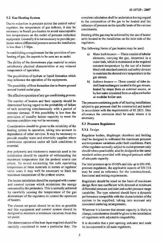
6.1.1 Operation of natural gas pressure regulating andmetering terminal follows automatic logic based on thephilosophy of uninterrupted supply of natural gas tothe customers.
Generally there are two streams of Pressure Regulator(PR) and Slam Shut-Valve (SSV) as per sketch givenbelow:
Ssvl PR 1h
SSV2 PR2
10
IS 15729:2007
In case of failure of Pressure Regulator (PR) and Slam 6.2.3 All the relevant safety precautions shall be taken
Shut-Valve (SSV) of one stream, it changes over to prior to any maintenance activity.
other stream automatically. The auto changeover is 6.2.4 After completion of major maintenance activities,achieved as follows: the equipment shall be put on-line.
6.1.2 An approved emergency action plan shall beprepared and kept at the terminal stations for handling
of emergencies at natural gas pressure regulating and
metering terminal.
6.1.3 A log, register shall be maintained at terminal to
record/communicate various general and miscellaneous
information.
6.1.4 Wherever on-line gas chromatography is
installed, it shall be ensured that the standard gas
being used is having the valid compositional stability.
The frequency of gas sampling should be on hourly
basis.
6.1.5 The terminal inlet valve shall be tested for remoteoperation (functional/actual as per site conditions)
annually, inapplicable.
6.2 Preventive Maintenance
6.2.1 There shall be an annual preventive maintenance
schedule for all the equipments of natural gas pressureregulating and metering terminal.
6.2.2 Preventive maintenance activities shall be carriedout as per schedule.
11
6.3 Maintenance Schedule
The maintenance frequency of various equipments may
be as per the table given below:
Instruments Frequency
Terminal inlet valve Once in a year
Filter Once in a year
Pressure control valve Once in a year
Slam shut-valve Once in a year
Fire alarm system Quarterly
Pressure transmitter Quarterly
Temperature transmitter Quarterly
Turbine flow meter Once in 2 years
To ensure that the metering system continues to perform
to its design accuracy, routine inspections andcalibration should be based on the required system
accuracy, the meter performance and any changes tothe process parameters. A record of a~} calibrationresults and equipment changes should be kept. Themaintenance of record filter and pressure regulator shallbe as per format given in Annex B and Annex C.
Regular inspection and maintenance of certified
electrical equipment shall be carried out in accordance
IS 15729:2007
with the certification requirements and should take
account of the manufacturer’s instructions and any
relevant standards. Documentation and records should
be kept to enable explosion-protected electrical and
electronic equipment to be maintained in accordancewith its type of protection.
The operation of the meter run and bypass valves shouldbe checked to ensure that they are capable of beingfully opened and fully closed and that any statusindication is correct. The valves should be tested toensure that they do not leak. Any leaks, wire seals, etc,used to indicate closure of bypass valves should be
checked regularly for integrity.
Relevant safety procedures concerning positive isolationof high pressure gas should be followed when removingmeters, orifice plates or other fittings form the line.
The pressure differential across filters should bechecked at predetermined intervals and filters cleaned/changed when necessary.
The maintenance practices for flow meters should be
followedaspertheirmanufacturers’recommendations.
The secondary equipments like pressure, temperaturetransmitter, etc, of metering system shall be calibrated
at regular intervals to ensure the correct firnctioning oftransmitters. The calibrations should be carried outusing a certified dead-weight tester traceable to nationalstandards. Calibration can be achieved directly using adeadweight tester or indirectly using a secondarystandard of known repeatability that has been verifiedagainsta Ce,fiifieddevice.
The instructions for operation and maintenance of filtershall include a description of the elements (includingthe number and type) and the method for detecting andremoving clogged elements.
At periodic intervals the analog inputs of flowcomputers should be calibrated. Also the data enteredin the flow computer should be verified at regularinterval and proper documentation should be maintained.
Prior to the start of the tests, the constants entered inthe flow computer should be recorded and checked.Checks should be carried out on the following:
a)
b)
c)
d)
e)
f)
~)h)
j)
Analogue to digital conversion;
Frequency inputs;
RTD temperature input;
Digital to analogue conversion;
Calculation of density, relative density andcalorific value of the gas;
Composition;
Calculation of flow rate;
Integration of flow rate; and
Check alarm functions.
When checking the calculation and integration of flowrate, using keypad values, all keypad inputs should bereturned to live inputs on completion of tests and allconstants recorded and checked.
Regular inspection and checking of electrical systemshould take place in accordance with the requirementsof IEC 60079-14. Adequate records of all maintenanceactivities should be kept.
The use of portable electrical equipment includingstandard generators should be restricted to zoned areasfor which they are certified.
Electrical maintenance personnel carrying out work inhazardous areas should receive special training and
certitied to show that they have received such trainingand are competent to carry out such work.
7 SAFETY ASPECTS OF THE SYSTEM
7.1 General
Safety procedures should conform to appropriatenational statutory requirements such as those given in
Factories Acts, Oil Industries Safety DirectorateGuidelines, etc, Relevant Codes and Specifications such
as the welding instructions, health and safety in weldingshould also be followed.
Wherever radiation sources are used or stored, properprovision for the safety of the public and personsemployed in the vicinity should be made in accordancewith the safety requirement of ISO 17636.
The safety aspect is divided into two parts — one issafety related with the process and another one is safetyrelated with the equipments. The gas despatch terminalsshould have following safety features:
a)
b)
c)
d)
e)
f)
12
Appropriate fire detection system may also beprovided.
Fire alarm system may be provided at gasdespatch terminal. The actuation of the firealarm should be through break glass system.
The main inlet valve of the terminal shouldbe actuated type and it should have provisionto close during emergency conditions eitherfrom master control room or from the local
control room. Also it should be closed in caseof actuation of fire alarm system.
All the pressure vessels should have suitablepressure relief valves as per the requirementof pressured vessel system.
Heater should have provision to trip at highertemperature.
In the downstream of pressure reductionsystem there should be suitable pressure reliefvalve to take care of failed situation of pressurecontrol valve/pressure regulator.
d
h)
j)
k)
m)
To take care of lightening a suitable lighteningarrester should be provided.
The pressure set-points of regulators and slam
shut-valves shall be selected in such a way
that in case of hot standby operation, the
failure of one pressure reduction stream should
not affect the continuous supply of gas to the
customer.
To avoid the failure of filter element a
differential pressure measurement should beprovided in the filters.
Terminal should be equipped with suitable fire
fighting equipments like extinguishers, fire
hydrant, etc. Appropriate fire protection
system should be installed at discretion of
asset operator depending upon size of gas
despatch terminal and risk involved.
While doing maintenance of the equipments
a suitable work permit system should befollowed considering the following points:
1)
2)
3)
4)
5)
6)
A regular gas leak check shall beconducted.
Smoking, naked lights or sources ofignition should not be allowed in the area,
and notices should be displayedaccordingly.
No entry should be made to pits,
buildings, or other confined spaces untilthe space is ventilated and the atmosphereis checked in accordance with factoryrules.
Appropriate Personal ProtectiveEquipments (PPE) shall be provided forall personnel on site and worn whennecessary.
Remotely operated valves may need tobe isolated prior to any work taking place.
On completion of the maintenance worka leakage check should be made beforeleaving the site.
7.2 Preparedness and Arrangements for EmergencySituation
Clear and effective emergency procedures andoperating instructions should be established for theguidance of all personnel connected with the operationand maintenance of pressure-regulating installations.The procedures should cover the possibility ofemergency situations arising in the supply of gas to ortlom the system, or resulting from leakage. In dealingwith any emergency situation the primary objectives
are to:
a) ensure the safety of the public and personnel,
b)
c)
IS 15729:2007
prevent damage to property and installations,and
minimize the extent of environmental hazardsand the effects of the emergent y.
The organization of routine work and the provision of
communications should be such that sufficient
supervisory and maintenance personnel can beimmediately alerted and dispatched to the installationsconcerned, wherever the installations are located. Inorder to cater for emergencies which arise outsidenormal working hours, the procedures should includethe action to be taken for calling out maintenance teams,supervisors and engineers in the order of priority.
Periodic exercises should be carried out to conformthe effectiveness of the emergency procedures.
8 COMMISSIONING OF THE TERMINAL
After fulfilling the requirements of this document the
installation can be commissioned. Before starting thecommissioning activities, a written commissioningprocedure should be prepared and issued tomaintenance personnel for each type of installation. Theprepared commissioning procedure should cover all theequipment installed at the terminal. In the preparation
of commissioning procedure the operation andmaintenance manual of equipments should be referred.The procedure should be carried out whenever an
installation is commissioned, wholly or in part. It is
essential that regulators are shown to be in full controlof the inlet pressure before installation outlet valvesare opened. The set-points of all pilots, controllers andregulators should be checked for each stream on load,preferably under high and low flow conditions.
The first step of commissioning is to identify/segregatethe whole installation in different sections with isolationand vent/drain provisions. Then the leak test is to becarried out. The details of leak test are given below.
The leak test medium should either be air or nitrogen.The test should be applied to the assembled installa~ionand should include all equipment and the associated
small bore pipelines.
The responsible engineer/supervisor should confirmthat all main, bypass and impulse valves are open. Theinstallation should be pressurized slowly up to therecommended test pressure.
All joints, flanges and glands on valves and fittingsshould be tested for leakage with a suitable foamingfluid. Any leakage should be made good by adjustmentor the remaking ofjoints where necessary.
The duration of a pneumatic test should be adequate toensure that the installation can be thoroughly inspected.The pneumatic test pressure should start fi-om minimum
13
IS 15729:2007”
of 0.7 MPa but consideration should be given toprogressively raising this minimum to a higher levelup to the maximum working pressure. This test maybe combined with the nitrogen purge prior tocommissioning.
After leak test the procedure for commissioningdescribed below should be followed.
on satisfactory completion of the leakage test, the testmedia should be safely vented to near atmospheric
pressure prior to testing for freedom tlom oxygen using
suitable test equipment. If necessary, a purge shouldbe carried out until the installation is shown to beoxygen-free by the use of suitable test equipment. Thenvent valves should be closed.
Where nitrogen has been used as a test media it shouldbe fully purged out using gas. When tests by suitableequipment show the installation to be completely fullof gas, all valves used for purging should be closed.
Vent and purge points should be carefully positionedto ensure all pipeline is purged.
ANNEX A
(Clause 2)
LIST OF REFERRED INDIAN STANDARDS
Incliutiltltern atiorlal IItle
Stundurd
2309:1989
2825:1969
5571:2000
5572:2004
11714 (Parts Ito 5) : 1986
13159(Part I): I993
15654:2006
15677:2006
Code of practice for the protectionof buildings and allied structuresagainst lightning (second
revision)
Code for unfired pressure vessels
Guide for selection of electricalequipment for hazardous areas
Classification of hazardous areas(other than mines) havingflammable gases and vapours forelectrical installation (secondrevision)
Specification for steel tubes forheat exchangers
Pipe flanges and flanged fittings
— Specification: Part 1 Dimensions
Supervisory control and dataacquisition for oil and gas pipelinesystem
Flow measuring of natural gas —Code of practice
[ndian/Internatio nal Title
Standard
1s0 14313:1999
1S0 17636:2003
IEC 60079-14{1996)
BSEN61152:1994
EN 334:2005
EN 12186:2000
EN 14382:2005
Specification for pipe line valves
Non-destructive testing of welds— Radiographic testing of fisionwelded joints
Electrical apparatus for explosivegas atmospheres — Part 14:Electrical installations inhazardous areas
Specification for dimensions oftemperature detecting elementsand corresponding pockets
Gas pressure regulators for inletpressures up to 100 bar
Gas pressure regulating stationsfor transmission and distribution— Functional requirements
Safety devices for gas pressureregulating stations and installa-tions — Gas safety shut-offdevices for inlet pressures up to100 bar
14
ANNEX B
(Clause 6.3)
MAINTENANCE FORMAT OF FILTER
Site
Unit No.
Date
S1No.
i)
ii)
iii)
iv)
v)
vi)
vii)
viii)
ix)
Job No.
Activities to be Undertaken
Perform the following before starting the work:
a) Place the fire extinguisher and fire hoses near themetering skid filter.
b) Isolate the filter, close all instrumentation tubings andopen the equalizing valve of differential pressuregauge/transmeter.
c) Repressurize the filter.
Remove the filter cover and inspect the ‘o’-ring.
Disengage the filter retainer and remove the filter element(s).
Clean the filter housing thoroughly before inserting thenew/cleaned filter element(s).
Clean the inside cover and place the ‘o’-ring after applying athin layer of grease.
Place the cover back and tighten as per the standard practice.
Charge the stream in steps after proper purging and checkingfor leakages.
Open the upstream valve and keep the stream as standby.
Close the equalizing valve of differential pressure gauge/transmeter.
Spares/Consumables Used
REMARKS
S1 No. Code No. Part No. Item Name Quantity Remarks
REMARKS (if any):
$IGNA1’LJRE
NOH: - Vendor manual to be referred before undertaking activities,
15
IS 15729:2007
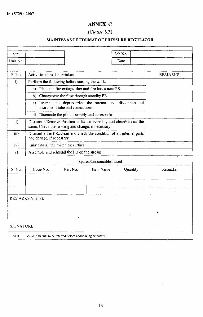
ANNEX C
(Clause 6.3)
MAINTENANCE FORMAT OF PRESSURE REGULATOR
aiiiE3 Job No.
Date
S1No. Activities to be Undertaken REMARKS
i) Perform the following before starting the work:
\ a) place the fire extinguisher and fire hoses nearpR. II b) Changeover the flow through standbyPR. I
c) Isolate and repressurize the stream and disconnect al}instrument tube and connections.
I d) Dismantle the pilot assembly and accessories. Iii)
iii) Dismantle the PR,.clean and check the condition of all internal partsand change, if necessary.
iv) Lubricate all the matching surface.
v) I Assemble and reinstall the PR on the stream. I
Spares/Consumables Used
S1 No. Code No. Part No. Item Name Quantity Remarks
REMARKS (if any):
SIGNATURE
N(YI’E — Vendor manual to be referred before undertabg activities.
16
IS 15729:2007
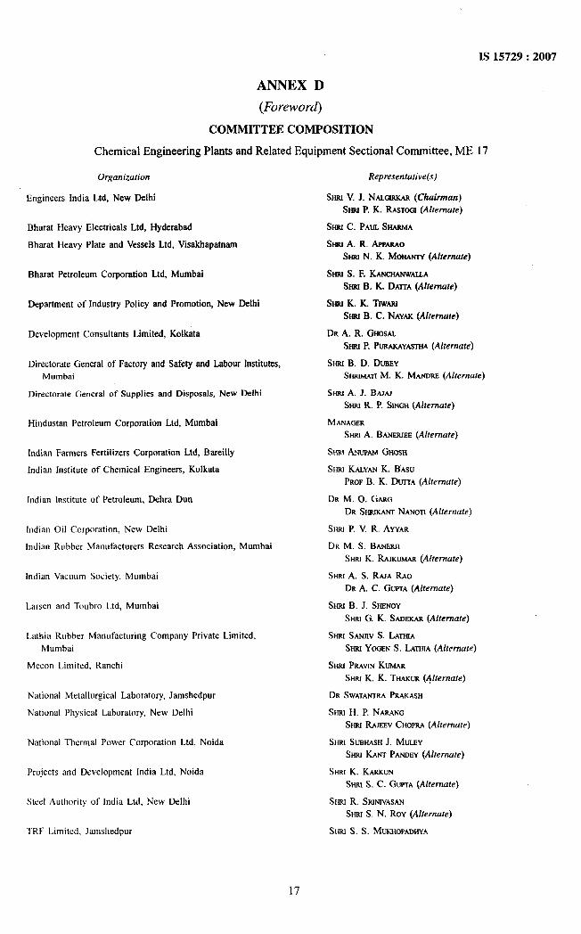
ANNEX D
(Foreword)
COMMITTEE COMPOSITION
Chemical Engineering Plants and Related Equipment Sectional Committee, ME 17
Orgunizution
Engineers India Ltd, New Delhi
Bharat Heavy Electrical Ltd, Hyderabad
Bharat Heavy Plate and Vessels Lid, Vkakhapatnam
Bharat Petroleum Corporation Ltd, Mumbai
Department of Industry Policy and Promotion, New Delhi
Development Consultants Limited, Kolkata
Directorate General of Factory and Safety and Labour Institutes,Mumbai
Directorate General of Supplies and Disposals, New Delhi
Hindustan Petroleum Corporation Ltd, Mumbai
Indian Farmers Fertilizers Corporation Ltd, BareiIly
Indian Institute of Chemical Engineers, Kolkata
Indian Institute of Petroleum, Debra Dun
Indian Oil Corporation, New Delhi
Indian Rubber Manufacturers Research Association, Mumbai
Indian Vacoom Society, Mumbai
Larsen and Toubro Ltd, Mumbai
Latbia Robber Manofacturiog Company Private Limited,
Mumbai
Mecon Limited, Ranchi
National Metallurgical Laboratory, Jamshedpur
National Physical Laboratory, New Delhi
National Thermal Power Corporation Ltd, Noida
Projects and Development India Ltd, Noida
Steel Aothority of India Ltd, New Delhi
TRF Limited. Jamshedpur
Repre.rentutive(s)
Sma V. J. NALGIRKAR(Chairman)
Mu P. K. RAwoor (Alternate)
%G c. PAUL SHARMA
%tt A. R. APPARAO
StrruN. K. MOHANTY(Alternate)
$kau s. F. KANCHANWALLA
SW B. K. DAITA (Alternate)
Smu K. K. TrWASU
SHRIB. C. NAYAK (Alternate)
DR A. R. GHOSAL
Smo P. PURAKAYASTHA(Alternate)
Srsa B. D. DUBEY
Smurwwr M. K. MANORE(Alternate)
SW A. J. BAJAJ
War R. P. SLNGr+(Ahernure)
MANAGER
Smu A. BANERJEE(Alternate)
SHSUANUPAMGHOSH
SHRI KALYANK. BASU
PROFB. K. DUtTA (Alternate)
DR M. O. GARG
DR SHMKANTNANOTt (Alternate)
Sruu P. V. R. AYYAR
DR M. S. BANERJI
SHRI K. RAIKW (Alrernu?e)
SHRIA. S. RAJA RAO
DR A, C. GUPTA(Alternate)
%0 B. J. %ENOY
SrmrrG. K. SAOEKAR(Alternate)
Smu SANJIVS. LATHIA
Ssmo YOGEN S. LATFUA(Alternate)
SNRI PRAWNKUMAR
Sriat K. K. THAKUR(Alternate)
DR SWATANTRAPRAKASH
SHRI H. P. NARANG
Ssuu RAJEEVCHOPRA(Akemute)
SNRI SUBHASHJ. MULEY
SHRIKANT PANOEY(Alternate)
War K. KARRUN
SMU S. C. GUPTA(Alternate)
SHSUR. SRtNtVASAN
Stnu S. N. ROY (Alternute)
SHRI S. S. MLKHOPAGHVA
17
IS 15729:2007
0r,yut7izutiofi
Zoari Industries Ltd (Fertilizer Division), Goa
131S Directorate General
Representative(s)
~ M. S. BANERJS
%at K. RAJKmrm(Alternate)
Smt C. K. VSDA, Scientist ‘F’ and Head (MED)
[Representing Direetor Generaf (Fk-qficio)]
Member SecretuqSHN ‘f. V. SIN~H
Scientist ‘E’ (MED), BIS
Panel of Natural Gas Pressure Regulating and Metering Terminal, ME 17/P-l
GAI1, India l.td, New Delhi
Engineers lodia Ltd, New Delhi
Emerson Process Management. Mumbai
Fluid Control f{escarch Institute, Kemfa
(iAll, fndia Ltd. Pata
Gujarat Gas Company Ltd. Surat
f{azim l,NG Pvt Ltd. Surat
Hincfustan Aeronautics Ltd, Bangafore
Ma!l&dore Retinery and Petrochemical Ltd, Mangalore
NTPC Ltd. Noida
Petroleum and Explosives Safety Organization, Nagpur
RMt3 Automcters Gas Technologies Ltd, Noida
Refiance Industries Ltd, Navi Mumbai
Tractebef E and C Pvt Ltd, New Delhi
SHRI E. S. RANCiANATIMN(Convener)
SHIUSURESHKUMAR
SHRJK. S. JARHAR(A[fernate)
SHRI SHAUESHpATtL
Stm[ R. MASCOMANI
Stau P. K, SORESH(A/rernuf<)
SNRI R.MVtANCHADHA
SHRIA. K. TIUPATHI(Alfemafe)
SHRI SADHANK. BANERJEE
SHRIVtPuLRANDESUZ(Alferrrufe)
SHIU KOMALKUMAR
SHRIMANISHTYAGI (A[ternute)
CDR (RETD) B. S. JAYANTH
SW R. NARASrMHA(Alternate)
SW A. GOPALKRISHNAPAI
SHRt SUBASHMOLEY
SHSURANTPANDEY(Alternate)
SHRIA. N. BISWAS
SHIUC. R. SURENDRAHNATHAN(Aherrrute)
Sr+ru P. K. R.&AN
War DAWOJ. MEAXtN(Alrerna?e)
SHRI S. JAYACHA~RAN
Smu K. K. Smo (Al femate)
Stuu V V. ANJANEYULU
Srrar FQnv MMNS (Alternafe)
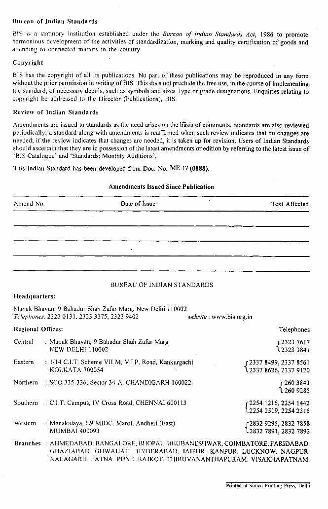
Bureau of Indian Standards
BIS is a statutory institution established under the Bureau of Indian Standards Act, 1986 to promoteharmonious development of the activities of standardization, marking and quality certification of goods andattending to connected matters in the country.
Copyright
B] S has the copyright of all its publications. No part of these publications may be reproduced in any formwithout the prior permission in writing of BIS. This does not preclude the free use, in the course of implementingthe standard, of necessary details, such as symbols and sizes, type or grade designations. Enquiries relating tocopyright be addressed to the Director (Publications), BIS.
Review of Indian Standards
Amendments are issued to standards as the need arises on the b;sis of comments. Standards are also reviewedperiodically; a standard along with amendments is reaffirmed when such review indicates that no changes areneeded; if the review indicates that changes are needed, it is taken up for revision. Users of Indian Standardsshou Id ascertain that they are in possession of the latest amendments or edition by referring to the latest issue of‘BIS Catalogue’ and ‘Standards: Monthly Additions’.
This Indian Standard has been developed from Dot: No. ME 17 (0888).
Amendments Issued Since Publication
Amend No. Date of Issue Text Affected
BUREAU OF INDIAN STANDARDS
Headquarters:
Manak Bhavan, 9 Bahadur Shah Zafar Marg, New Delhi 110002Telephones: 23230131,23233375,2323 9402 website ; www.bis.org.in
Regional Offices: Telephones
Central :
Eastern :
Northern :
Southern :
Western :
Branches :
Manak Bhavan, 9 Bahadur Shah Zafar Marg{
23237617NEW DELHI 110002 23233841
1/14 C.I.T. Scheme VII M, V.I.P. Road, Kankurgachi{