Disclosure to Promote the Right To Information Whereas the Parliament of India has set out to provide a practical regime of right to information for citizens to secure access to information under the control of public authorities, in order to promote transparency and accountability in the working of every public authority, and whereas the attached publication of the Bureau of Indian Standards is of particular interest to the public, particularly disadvantaged communities and those engaged in the pursuit of education and knowledge, the attached public safety standard is made available to promote the timely dissemination of this information in an accurate manner to the public. इंटरनेट मानक “!ान $ एक न’ भारत का +नम-ण” Satyanarayan Gangaram Pitroda “Invent a New India Using Knowledge” “प0रा1 को छोड न’ 5 तरफ” Jawaharlal Nehru “Step Out From the Old to the New” “जान1 का अ+धकार, जी1 का अ+धकार” Mazdoor Kisan Shakti Sangathan “The Right to Information, The Right to Live” “!ान एक ऐसा खजाना > जो कभी च0राया नहB जा सकता ह ै” Bhartṛhari—Nītiśatakam “Knowledge is such a treasure which cannot be stolen” IS 6006 (1983): uncoated stress relieved strand for prestressed concrete [CED 54: Concrete Reinforcement]
Transcript
Disclosure to Promote the Right To Information
Whereas the Parliament of India has set out to provide a practical regime of right to information for citizens to secure access to information under the control of public authorities, in order to promote transparency and accountability in the working of every public authority, and whereas the attached publication of the Bureau of Indian Standards is of particular interest to the public, particularly disadvantaged communities and those engaged in the pursuit of education and knowledge, the attached public safety standard is made available to promote the timely dissemination of this information in an accurate manner to the public.
इंटरनेट मानक
“!ान $ एक न' भारत का +नम-ण”Satyanarayan Gangaram Pitroda
“Invent a New India Using Knowledge”
“प0रा1 को छोड न' 5 तरफ”Jawaharlal Nehru
“Step Out From the Old to the New”
“जान1 का अ+धकार, जी1 का अ+धकार”Mazdoor Kisan Shakti Sangathan
“The Right to Information, The Right to Live”
“!ान एक ऐसा खजाना > जो कभी च0राया नहB जा सकता है”Bhartṛhari—Nītiśatakam
“Knowledge is such a treasure which cannot be stolen”
Joint Sectional Committee for Concrete Reinforcement, BSMDC 8
, ClatJirmn
SHIH G. S. RAO
RtprlstntingCentral Public Works Department, New Delhi
Mt'lltbnsSUPERINTENDING ENGJNEER
( CDO ) ( Alt.1UJI, toSbri G. S. Rao )
DR J. L. AJKANI The Tata Iron & Steel Co Ltd, ]amshedpurSHRI A. N. MI'l'RA ( Allmaat, )
DR AJtlL KUIIAR Cement Research Institute of India, New DelhiSHRI E..T. ANTIA The Concrete Association of India, Bombay
SSRI P. SRINIVASAN ( AlImaal, )Sm\! S. BANERJD Steel Re-Rolling Mills Association of India, CalcuttaSBRI S. N. CIIANDA Metallurgical and Engineering Consultants (India)
Ltd, Ranchi5HRI R. D. CHOUl>HA1,y ( All.,.." )
CHIEJ' EHOI1QmB ( D&.R ) Irrigation Department, Government of Punjab,Chandigarh
DIRECTOR ( CD ) ( -Alt"lIat,)DEPUTY DIRECTOR, STANDARDS Research. Designs & Standards Orlanization
( BitS )-1 ( Ministry of Railways), LucknowAasJ8TAJIT DIREOTOR, STAN-
DARDS ( B&S )-11 ( Altlnatll, )SIIRI D. I. DESAI Gammon India Ltd, Bombay
Saal A. L. BUATIA (Alt".".',)SHar M. R. DOCTOR Special Steels Ltd, Bombay
SHar S. G. J08Hl ( Altml4l, )SaRI Z ...OBABIA GBOROB Structural Engineering Research Centre (CSIR),
MadrasSSRt G. V. SURYAKVIIAR ( .AI",.,..,. )
( Contin",d0,. /NIl' 2 )
<e Co/J.1ritlal 1983BUREAU OF INDIAN STANDARDS
Tbil publication is protected under the ItttIitm Co/J:1ri,Jal Ad (XIV of 1957) andreproduction in whole or in part by any means except with written permission of thepubliaber "II be deemed to be aD infrinpment of copyright under the said Act.
II I 6006• 1983
( Conlinu,d from ptJg' I )
Director General, lSI ( Ex-officio Member )
Public Works Department, I...ucknowM. N. Dastur & Co ( P ) Ltd, Calcutta
Hindustan Construction Co Ltd, Bombay
~I,mb,rs
SHUI V. K. GHANEKAR
Representing
Structural Engineering Research Centre (CSI R ),Roorkee
SHltl D. S. PRAK .~~J( R AO ( Alternat« )SHRI V. GeLATI Heatly & Gresham ( India) Ltd, New DelhiSHltJ P. K. GUPTE National Metallurgical Laboratory (CSIR),
JamshedpurSIIlH N. C. JAIN Stup Consultants Ltd, Bombay
SHRt ~f. C. TANDOS ( Alternate )SHIel M. P. JASUJA Steel Authority of India Limited (Research &
Development Centre for Iron and Steel ), RanchiSHR I A. J.~Y AHOP A I, Engineer-in-Chief ts Branch, Army Headquarters
M.\J R. ClI ..\NDtL\SEKH.\tL\~ ( Alternate)SHRI S. Y. KHAN' Killick Nixon Ltd, Bombay
5MBI P. S. \'ENKAT ( Alternate )Snn i M. N. KHANNA Steel Authority of India Limited (Bhilai Steel
Plant ), BhilaiSHRI C. DASOUPTA ( Alternate)
SHIH H. N. KtUSHN A MURTHY Tor Steel Research Foundation in India, CalcuttaDR C. S. V IS\V A S.\ l' IL\ ( Alternate)
Snur S. N. ~1 ~soJl:\n 'rata Consulting Engineers, BombaySIIRI N. x .\nAIL\.J ( Alternate )
SURI R. K. ~IL\'r II U It
SHRIS.N PALSHRI S,\1.1L RoY ( Allernal,)
SHR! B. K. PANT" AXY
SHR' P. V. ~AIK ( Altemat« )SURI T. S";N IRe Stee-ls Ltd, C·dcuttaS lIRI M. V. S H .'\STRY Ministry of Shipping and Transport ( Roads \Vin,g )SHRI SHIRtAH H. SHAH Tensile Steel Ltd, Bornbay
SHitI M. S. PATHAK ( AllertllJte)SHRI C. N. SK)N(VAS.~N C. R. Narayana Rao, Madras
SURI C. N. RAQHAVP;~DH.\N ( Alternat« )SURI K. S. SRlS"IVASAN National Buildings Organization, New Delhi
(Fag_ 9. TabZe 3, col 2. 12th entry) - Substitute'12.7 .. l-ply' fir '12.51D1D 7-ply'.
(BSK><: 8)
Printed at Simco 'rlntlng Prnl. Deihl. India
JANUARY 1988AMENDMENT NO. :2TO
IS I 6006· 1983 SPECIFICATION FORUNCOATED STRESS RELIEVED STRAND FOR
PRESTRESSED CONCRETB
( Fir.' Re"i.ion J(Pag, 5, ,IGUS' 2.6) - Substitute the following for the existing
clause:'2.6 Prociactloa Lea.tla - The maximum length of strand that canbe manufactured without or with welds (SI' 3.3) being made afterdrawing in any of its component wire.'
(P.g,8, Tdbl, 2) - Substitute the following for the existing table:
TABLE 2 DIMENSIONS, TOLERANCES AND MASI OP SEVENWIRE STRANDS
NOTB - The Dominal eros.·lection.1 .rea aDd the Dominal mua of the Itraadare liveD for informatioD only_
1
( Pag,9, Tabl« 3) - Substitute the following for the existing table:
TABLE 3 MINIMUM BREAKING LOAD
( Cltuu,s 6.1 J 6.2 and 7.2.1 )
CLA88 DElICH ATION BREAKING LOAD 0·2 P.~IlCUT
Mi" 'BOOI' LoADMill
( I) (2) (3) (.)
N N2-ply 2 mm 12750 10840
2-ply 3 mm 25500 21670
3-ply 3 mm 38250 32460
6-3 mm 7-ply 40000 34000
7-9 mm 7-ply 64500 M700
9·5 mm 7-ply 89000 75600
11-1 mm 7-ply 120 100 102 300
12"7 mm 7-ply 160100 136200
15·2 mm 7-ply 240200 204200
I 9"5 mm 7-ply 102300 87000
11·1 mm7-ply 137900 117200
12·' mm '-ply 183709 156100
15"2 mm 7-ply 260700 221500
(Pal' 10, ,laus, 7.2.1, first smunc ) - Substitute the following forthe existing sentence:
•Alternatively, the load at 1·0 percent extension method may abo bedetermined. t
(BSMDC8 )
2
Printed at Simco Prlntlna Pr.... Deihl. India
AMENDMENT NO.3 JUNE 1993TO
IS 6006: 1983 SPECIFICATION FOR UNCOATEDSTRESS RELIEVED STRAND FOR PRESTRESSED
CONCRETE
( First Revision)
( Pages 8 and 9, clause 6.3 ) - Substitute tbe following for the existingmaner:
'6.3 Elongation - Elongation of tbe strand shall not be less than 3.5 percentand shall be measured on a gauge lengtb of not less than 200 mm for 2-ply and3-ply strands and not less than 600 mmfor 7-ply strands.
The elongation sball be measured by a suitable extensometer wbich is attached tothe test piece, after an initial load equivalent to 10 percent of the requiredrninimum breaking load as specified in Table 3 has been applied.
Following an extension of 1 percent, the extensometer may be removed andloading continued to ultimate failure. The elongation value is then determined bytbe movement between tbe jaw gripping tbe test piece on the new base length ofjaw-to-jaw distance to whicb will be added tbe value of 1 percent determined bytbe extensometer.'
( Page 9, Table 3 (see also Amendment No.2)] -Insert the following Notebelow tbe Table:
'NOTE - The modulus of el~slicilY is 10 be taken as 195 ± 10 KN/mm2, unless otherwise
indicated by Ihe manufacturer"
(CEO S4)Reprolraphy Unit, 81S, New Delhi, hadia
AMENDMENT NO. 4 JUNE 1997TO
IS 6006: 1983 SPECIFICATION FOR UNCOATEDSTRESS RELIEVED STRAND FOR· PRESTRESSED
CONCRETE( FirstRevision)
(Page 4, clauseZ.4) - Substitute the following for tbe existing clause:
'%.4 Length or fAly - The distance (measured along a stllight Jine parallel tothe strand) in which a wire forms one complete helix.'
(Page 6, clause3.3.% ) - Delete the last word '(patenting)'.
( Page 10, clause 8.1 ) - Substitute the following for the existing clause:
'8.1 For 7-ply strand coils, test samples of sufficient length to permit the testsCor breaking load, proof load, and elongation shall be selected, at random, froma group of 5 coils; but sample size shall not be less tban 2 from each lot.
For 2-ply and 3-ply strand coils, test samples shall be selected at random fromeach lot in accordance with following table:
No. ofcoils in the lot No. ofcoils to be selected
Up to 2526 to 6S66 "1801'81 "300301 and above
3457
10'
(Page 12, clause 10.1.% ) - Insert the following new clause after 10.1.1:
'10.1.3 By mutual agreement between the purchaser and the manufacturer,water soluble oil may beapplied on strands.'
(CED54 )
Reprography Unit, BIS,New Delhi, India
1.1'..·1-Indian Standard
SPECIFICATION FORUN:COATED STRESS RELIEVED STRAND FOR
PRESTRESSED CONCRETE
( First Revision)
o. FOREWORD
0.1 This Indian Standard ( First Revision) was adopted by the IndianStandards Institution on 14 March 1983, after the draft finalized by theJoint Sectional Committee for Concrete Reinforcement had beenapproved by the Civil Engineering Division Council.
0.2 This standard was first published in 1970 to cover the requlrementsof strands used in prestressed concrete work. The present revision hubeen taken up with a view to incorporating modifications found necessaryas a result of use of this standard both by manufacturers and users.
0.3 The significant modifications incorporated in this revision are inrespect of provisions relating to physical requirements of nominal manof strand and proof load and the sample size for tensile test. Further,SI units have been adopted in the revision and references to relatedIndian Standards appearing in the standard have been updated.
0.4 In the formulation of this standard, due weight age has been givento international co-ordination among the standards and practicesprevailing in different countries in addition to relating it to the practicesIn the field in this country,
0.5 For the purpose of deciding whether a particular requirement ofthis standard is complied with, the final value, observed or calculated,expressing the result of a test shall be rounded off in accordance withIS: 2·1960*. The number of significant places retained in the rounded offvalue should be the lame as that of the specified value in this standard.
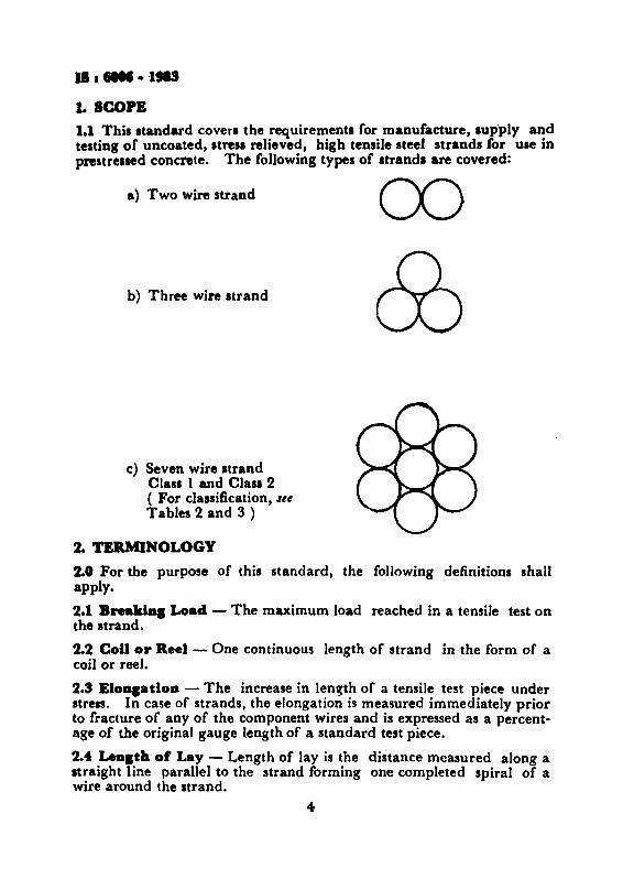
1.ICOPE1.1 This standard covers the requirements for manufacture, supply andtesting of uncoated, stresl relieved, high tensile steel strands for use inprestreased concrete, The following types of strand. are covered:
a) Two wire strand
b) Three wire strand
c) Seven wire strandCla.s 1 and Clan 2( For classification, letTables 2 and 3 )
2. TERMINOLOGY
2.0 For the purpose of this standard, the following definitions shallapply.
2.1 BnaIda, Load - The maximum load reached in a tensile test onthe strand.
2.2 CoD or Reel - One continuous length of strand in the form of acoil or reel.
2.3 EloDlatloD - The increase in length of a tensile test piece understress. In case of strands, the elongation is measured immediately priorto fracture of any of the component wires and is expressed as a percentage of the original gauge length of a standard test piece.
2.4 Lealth 01 Lay - Length of lay is the distance measured along astraight line parallel to the strand forming one completed spiral of awire around the strand,
4
IS I '6006 • 1985-
2.5 Parcel - Any quantity of finished strand presented for examinationand test at anyone time.
2.6 P.-oduction LeDgth - The maximum length of strand which canbe manufactured without welds being made after drawing in any of itscomponent wire.
2.7 Proof Load - The load which produces a residual strain of0·2 percent of the original gauge length ( non-proportional elongation ).
2.8 Seve~ Wire Strand - Any length of finished material whichcomprises six wires spun together in helical form around a central wire.
2.9 Three ""ire Strand - Any length of finished material whichcomprises three wires spun together in helical form.
2.10 Two Wire Straad - Any length of finished material whichcomprises two wires spun together in helical form.
3. MANUFACTURE
3.1 Wire
3.1.1 The base metal shall be carbon steel of such quality that whendrawn to suitable round wire sizes and fabricated into proper strand ...sizes .and properly stress relieved after stranding, shall have theproperties and characteristics as prescribed in this specification.
3.1.2 The element wire to be used for strand shall be cold-drawn fromplain carbon steel ( Jtl 3.1.1 ) and shall contain not more than 0-050 percent of sulphur and not more than 0·050 percent of phosphorus, whentested in accordance with relevant parts of IS : 228*.
3.1.2.1 The wire used in the manufacture of the strand shall be welland cleanly drawn to the specified dimensions and shall be sound andfree from splits, surface flaws, piping, and any other defects likely toimpalr its use in the manufacture of the strand and the performance ofthe strand -in prestressed concrete.
3.2 8traad - The seven wire strand shall have a centre wire at leastIi percent greater in diameter than the surrounding wires enclosedtightly by six helically piaced outer wires with a uniform length of Jayof at least 12 times but not more than 16 times of the nominal diameterof the strand. The length of lay for the two and three wire strandsIhaJI be uniform throughout and shall be 24 to 36 times the diameter ofelement wire. The wires in the strand shall be so formed that they shallnot unravel when the strand is cut and they shall not fly out of positionwhen the strand is cut without seizing.
·Method. of chemical analysis of steel" ( sN.1Ul rft/is;',. ) ( h,;", issu,d in ~,ts ).
5
II I 6006 • 1983
9.3 Jolat.
3.3.1 There shall be no strand joints or strand splices in any length ofthe completed strand unless specifically permitted by the purchaser.
3.3.2 During process of manufacture of individual wires for stranding,welding is permitted only prior to or at the size of the last heat treatment ( patenting ).
3.3.3 During fabrication of the 7 wire strand, butt-welded joints maybe made in the individual wires, provided there is not more than onesuch joint in any 45 m section of the completed strand.
N")'rB - When specifically ordered as weldless grade, a product free of welds shallbe supplied. \Vhen this grade is specified, no welds or joints are permitted except asdetailed in 3.3.2. .
3.4 Stre•• RelievlDI or Strand - "After stranding, all strands shall besubjected to a stress-relieving. Stress relieving shall be carried out as acontinuous process on a length of strand by uncoiling and runningthrough any suitable form of heating to produce the prescribedmechanical properties. Temper colours, which may result front thestress-relieving operation, shall be considered normal for the finishedappearance of the strand.
A fter stress relieving, the strand shall be reformed into coils orwound on to reels, having core diameter of sufficient size and in any casenot less than 600 rom to ensure that the strand will layout straight.
3.5 Workman.hip aad Finish - The finished strand shall be uniformin diameter and shall be free from injurious flaws and imperfections.The strand shall not be oiled or greased. Slight rusting, provided it isnot sufficient to cause pits visible to the naked eye, shall not be a causefor reject ion.
4. SIZE AND DESIGNATION
4.1 Two Wire Strand - The nominal diameter, the nominal crosssectional area and the nominal mass per unit length of the strand shallbe as given in Table 1.
4.1.1 The two wire strand shall be designated by the number ofelement wires ( plies) and the diameter of the element wire making thestrand, for example, 2-ply 2 mm strand will mean a strand consisting oft\VO element wires of diameter 2 0 mrn each.
4.2 Three Wire StraDd - The nominal diameter, the nominal crosssectional area and the nominal mass per unit length of the strand shallbe as given in Table 1.
6
IS I 6006 • 1983
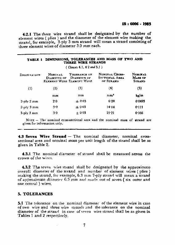
4.2.1 The three wire strand shall be designated by the number ofelement wires ( plies ) and the diameter of the element wire making thestrand, for example, 3-ply 3 rom strand will mean a strand consisting ofthree element wires of diameter 3.0 mm each.
TABLE 1 DIMENSIONS, TOLERANCES AND MASS OF TWO ANDTHREE WIRE STRANDS
( Clauses 4.1, 4'2 arul5.1 )
DF:SIO~A'J lOS NOMINAL TOLERANCE ON NOMINAl.. CROBS- NOMINALDJAMETER OF DIAMETER OF SJ!:CTIONAL AREA MA88 01'
ELEMENT WIRE ELEMENT WntE OF STRANO STRAND
(1) (2) (3) (4) (5)
mm mm mm' kg/m
2-pJy 2 mm 2'0 ± 0'03 6'28 0'0493
2-pJy 3 mrn 3'0 :!: 0'03 14·14 0·1 JI
3-ply 3 rom 3'0 ± 0'03 21'21 0·166
NOTE - The nominal cross-sectional area and the nominal mass of strand aregiven for information only.
4.3 Seven Wire Straad - The nominal diameter, nominal crosssectional area. and nominal mass per unit length of the strand shall be asgiven in Table 2.
4.3.1 The nominal diameter of strand shall be measured across thecrown of the wires.
4.3.2 The seven wire strand shall be designated by the approximateoverall diameter of the strand and number of element wires ( plies)making the strand, for example, 6.3 m m 7-ply strand will mean a strandof approximate diameter 6.3 rom and made out of seven ( six outer andone central) wires.
5. TOLERANCES
5.1 The tolerance on the nominal diameter of the element wire in caseof two wire and three wire strands and the tolerance on the nominaldiameter of the strand in case of seven wire strand shall be as given in"fables 1 and 2 respectively.
7
.1, .-&·1983
TABU 2 DIMENSIONS, TOLERANCES AND MASS OF SEVENWD\' 111l4NQS( Ct-uu 4.3 4.d 5.1 )
CLASS nBBIONATION NOMINAL TOLERANCE ON NCKNAL NOMJlfAJ~DI AIIJ:TE.R THE NOMINA.L CROBB-SEC- MASS OJ'0 .. STRAND DIAMETER OF TIONAL AREA STRAND
SRTAND OF STRAND
(1) (2) (3) (4) (5) (6)
rom mm mm! kg/m
6"3 mm 7-ply 6·3 ::f: 0"4- 25'1 0·195
7"9mm 7-ply 9.7 ± 0"4- 37'4 0·295
9·S mm 7-ply 9·S ±O·. 51"6 0-408
11°1 rom '-ply 11·1 :i: 0"4- 70·3 0·555
12°7 mm 7-ply 12°7 :i: 0·4- 92°9 00730.
15-2 mm '-ply 15-2 ± 0"4 138°7 1·094-
2 9"Smm 7-ply 9°5 + 0·66 54"8 0·435- 0·15
11·1 mm '-ply J1·1 + 0·66 74"2 0°585- 0"15
12°7 mm '-ply 12°7 + 0"66 98·7 0·775- 0"15
15"2 mm 7-ply 15"2 + 0·66 140'0 1·102- 0°15
NOTE - The nominal cross-sectional area and the nominal mass of the strand are..given for information only.
6. PHYSICAL REQUIREMENTS
6.1 BreaklaS StreD,th - The breaking load of finished stress relieved'strand determined in accordance with 7.1, shall not be less than thevalues given in Table 3_
6.1.1 Tests in which fracture of any of the wires occur within adistance of 3 mm from the jaws of the machine shall be discarded, if theresults do not comply with the requirements of this specification.
&.2 Proof Load - The 0-2 percent proof load of the strand tested inaccordance with 7.2, shall be not less' than the values speclfied in Table 3.
6., EloDptloD - Elongation of the strand measured on a gaugelength of not less than 600 rom by means of a suitable extensometer
9·S mm 7-plylief mID 7·ply12-5 mm 7-ply15·2 mm 7-ply
B••AKUfO LoADMitt
(3)
N
12 75025 50038 250
44·48068 95093 410
124 5401M 580226 860
102 SIO137 810183 710261 440
0-2 PaOD'l'Paool' LoAD
(41N
10 84021 67032 460
57 81058 60079 400
105 860159 900192 8SO
86 960117 210156 ISO222 2SO
.ttached to th~ test piece shall be not Ie•• than 3·5 percent immediatelyprior to fracture of any of the component wire ( s" 7.s ).
..4 Relasadoa - The relaxation Itresl in the wire, when tested inaccordance with 7." shall not exceed ~ percent of the initial Itrea uspecified in 7.4 at the end of I 000 h. Alternatively the manufacturershall provide proof that the quality of wire supplied is such u to complywith thil requirement.
6.4.1 When it is not possible to conduct 1 000 h relaxation test,. thewire maybe accepted on the basis of 100 h relaxation tett provided themanufacturer furnishes proof establishing a relation between relaxation·stress values at 1 000 hand 100 h and provided that the relaxation Itres.-at 100 h is not more than 3-50 percent of the initial stress as specifiedin 7.4.7. TESTS
7.1 TeD.lle Te.t - The breaking load shall be determined in accordanee with IS : 1521·1972·.
7.2 Tnt lor Prool Load - Proof load shall be determined in accordance with IS : 1521·1972•.
*Method tor tensile testin, of .tett) wire (firs' ,lVision ).
9
1I.M6 ·1983
7.2.1 The 'load at 1·0 percent extension' method may be used by agreement between the manufacturer and the perchaser. In this test, an initialload equivalent to 10 percent of required minimum breaking strengthas prescribed in Table 3 shall be applied to the test piece and a sensitiveextensometer then attached. The dial of the latter shall be adjusted toread 0·001 mm/mm of the gauge length to represent the extension due tothe initial load.
The load shall be increased until the extensometer shows an extension corresponding to 1·0 percent. The load at this extension shall notbe less than the minimum 0·2 percent proof load specified in Table 3.
7.3 EloDlatioD Test - The elongation shall be determined in accordance with IS : 1521-1972*.
7.4 Te.t for RelasatioD - If required by the purchaser, the manufacturer shall provide evidence from records of tests of similar strandthat the relaxation of load from an initial stress of 70 percent of thespecified minimum tensile strength ( calculated from the minimum specified breaking load and the nominal cross-sectional area of strand)conforms to that specified in 6.4. During the whole period of test thetemperature shall be maintained within the range 20 ± 2°C. The initialload shall be applied in a period of 5 minutes and shall then be heldconstant for a further period of one minute. Thereafter no adjustmentof load shall be made, and load relaxation readings shall commencefrom the end of the sixth minute. On no account shall the test specimenbe overstressed.
8. SAMPLING AND CRITERIA FOR CONFORMITY
8.1 Selection of Te.t Sample. - 'fest samples of sufficient length topermit the tests for breaking load and elongation shall be cut from oneend of every fifth coil, but sample size shall not be less than 2 from eachlot. A further length shall be cut from each fin h coil or part of 5 coilsfor the determination of proof load.
8.1.1 All test pieces shall be selected by the purchaser or his authorizedrepresentative. The test piece shall not be detached from the (oil orlength of strand, except in the presence of the purchaser or his authorizedrepresentative.
8.1.2 Before test pieces are selected, the manufacturer or supplier shallfurnish the purchaser or hi, authorized rep. esentative with copies of themill records giving number of coils in each cast with sizes as well as theidentification marks, whereby each coil can be identified.
·Method for tensils testing of steel wire (first recision ).
10
II I 6001 ~ 1.
8.2 Bet..t - Should any sample fail any of the tellI, by agreement -, .between manufacturer and purchaser, two additional test lamp). fromthe same end of the same coil shall be taken and subjected to the teat ortests in which the original sample failed. Should both additional _samples pass the test or tests, the coil from which they were taken lhallbe deemed to comply with the requirements of this standard. Shouldeither of them fail, the coil shall be deemed not to comply.
8.3 If ten percent or more of the selected coils rail to fulfil the requirements of the standard, the parcel from which they were taken shall bedeemed not to comply with this standard.
s, DELIVERY, INSPECTION AND TESTING FACILITIES
9.1 Unless otherwise specified, general requirements relating to thesupply of material, inspection and testing shall conform to IS : 13871967·,
'9.2 No material shall be despatched from the manufacturer's or suppliers'premises prior to its being certified by the purchaser or his authorizedrepresentative as having fulfilled the tests and requirements laid downin this standard except where the coil or reel containing the strand ismarked with the lSI Certification Mark.
-9.3 The purchaser or his authorized representative shall be at liberty toinspect and verify the steel maker's certificate of cast analysil at thepremises of the manufacturer or supplier; when the purchaser requires 'An actual analysis of finished material, this shall be made at a placeagreed to between the purchaser and the manufacturer or the supplier.
9.4 Maaalactarer'. CertHieate - In the case of strands which haveDot been inspected at the manufacturer's work the manufacturer or-supplier, as the case may be, shall supply the purchaser or his authorizedrepresentative with the certificate stating the process of manufacture and
. also the test sheet signed by the manufacturer giving the result of eachmechanical test. 0·2 percent proof load and the chemical composition, ifrequired. Each test sheet shall indicate the number or identificationmark of the cast to which it applies, corresponding to the Dumber or·ldentification mark to be found on the material.
10. PACKING, mF..NTD1CATION MARKING
1'.1 Unless otherwise agreed to between the purchaser and the supplier.-;the strands shall. besupplied as indicated in 10.1.1 or IO~l.2.
*GfDeraI reqUlrem~Dta for the IUpply of metallurPcaI materiala (fi's' mlisiM ).
)1
IS I 6006 • 1983
10.1.1 Strands shall be wound into traversed layered coils having aninternal diameter of a size as specified in 3.4. These coils shall be securelystrapped to prevent distortion of the coil in transit and unless otherwisespecified the coils shall be protected against damage in transit by wrapping with hessian.
10.1.2 Strands shall be coiled on to suitable reels having a core diameter of not less than 600 mm.
10.2 The manufacturer or supplier shall have coils of strands marked insuch a way that all finished strand can be traced to the cast from whichthey were made. Every facility shall be given to the purchaser or hisauthorized representative for tracing the strands to the cast from whichthey were made. Each coil shall carry a label giving the followingdetails:
a) Size of strand;b) The coil number; andc) Class, where applicable.
10.2.1 Each coil containing the strands may also be suitably markedwith the lSI Certification Mark in which case the concerned test certificates shall also bear the Standard Mark.
NOTE - The use of the Standard Mark is lovemed by the provisioDl of the BureauofIndian Standards Act, 1986 and the R.les aDd Reaulations made thereunder. TheStaDdardMark on prodUCIi covered by aD ladiaD S1IDdardcoDveys the.......ce that they have beeDproduced 10 comply with abe reqaireme... of that .taDdard UDder • well clefaaecl.,.II.. ofiDlpectioD, leaIia. ud quality co.trol whichi. cIeviIecIaDClsupeM" by SIS ud operaledby the producer. 5tuclard marbd produetl are also coatiD.UIly cbeebd by DIS forcoaformity 10 thai aaalldard u • furdaer .fepard. De&aila of CODCIidou ....r WIaicb I
liceace for tbe.. of'" Staaclard MarkIDlybe11'0" to mlDufachUen or procIucelllU,be obtaiDed from IbeBuea. of IDcIiaD StaDClarda.