1 Is NOMA Efficient in Multi-Antenna Networks? A Critical Look at Next Generation Multiple Access Techniques Bruno Clerckx, Senior Member, IEEE, Yijie Mao, Member, IEEE, Robert Schober, Fellow, IEEE, Eduard Jorswieck, Fellow, IEEE, David J. Love, Fellow, IEEE, Jinhong Yuan, Fellow, IEEE, Lajos Hanzo, Fellow, IEEE, Geoffrey Ye Li, Fellow, IEEE, Erik G. Larsson, Fellow, IEEE, and Giuseppe Caire, Fellow, IEEE In the past few years, a large body of literature has been created on downlink Non-Orthogonal Multiple Access (NOMA), employing superposition coding and Successive Interference Cancellation (SIC), in multi-antenna wireless networks. Furthermore, the benefits of NOMA over Orthogonal Multiple Access (OMA) have been highlighted. In this paper, we take a critical and fresh look at the downlink Next Generation Multiple Access (NGMA) literature. Instead of contrasting NOMA with OMA, we contrast NOMA with two other multiple access baselines. The first is conventional Multi-User Linear Precoding (MU–LP), as used in Space-Division Multiple Access (SDMA) and multi-user Multiple-Input Multiple-Output (MIMO) in 4G and 5G. The second, called Rate-Splitting Multiple Access (RSMA), is based on multi-antenna Rate-Splitting (RS). It is also a non-orthogonal transmission strategy relying on SIC developed in the past few years in parallel and independently from NOMA. We show that there is some confusion about the benefits of NOMA, and we dispel the associated misconceptions. First, we highlight why NOMA is inefficient in multi-antenna settings based on basic multiplexing gain analysis. We stress that the issue lies in how the NOMA literature, originally developed for single-antenna setups, has been hastily applied to multi-antenna setups, resulting in a misuse of spatial dimensions and therefore loss in multiplexing gains and rate. Second, we show that NOMA incurs a severe multiplexing gain loss despite an increased receiver complexity due to an inefficient use of SIC receivers. Third, we emphasize that much of the merits of NOMA are due to the constant comparison to OMA instead of comparing it to MU–LP and RS baselines. We then expose the pivotal design constraint that multi-antenna NOMA requires one user to fully decode the messages of the other users. This design constraint is responsible for the multiplexing gain erosion, rate and spectral efficiency loss, ineffectiveness to serve a large number of users, and inefficient use of SIC receivers in multi-antenna settings. Our analysis and simulation results confirm that NOMA should not be applied blindly to multi-antenna settings, highlight the scenarios where MU–LP outperforms NOMA and vice versa, and demonstrate the inefficiency, performance loss, and complexity disadvantages of NOMA compared to RSMA. The first takeaway message is that, while NOMA is suited for single-antenna settings (as originally intended), it is not efficient in most multi-antenna deployments. The second takeaway message is that another non-orthogonal transmission framework, based on RSMA, exists which fully exploits the multiplexing gain and the benefits of SIC to boost the rate and the number of users to serve in multi-antenna settings and outperforms both NOMA and MU–LP. Indeed, RSMA achieves higher multiplexing gains and rates, serves a larger number of users, is more robust to user deployments, network loads and inaccurate channel state information and has a lower receiver complexity than NOMA. Consequently, RSMA is a promising technology for NGMA and future networks such as 6G and beyond. Index Terms—Multiple antennas, downlink, non-orthogonal multiple access, superposition coding, rate-splitting multiple access, broadcast channel, multiuser linear precoding, multiuser multiple-input multiple-output, space division multiple access, next generation multiple access. I. I NTRODUCTION This work has been partially supported by the EPSRC of the UK under grant EP/N015312/1, EP/R511547/1, by the Australian Research Council Discovery Projects under Grant d DP190101363 and in part by the Linkage Project under Grant LP170101196, and by the European Research Council’s Advanced Fellow Grant QuantCom (Grant No. 789028). Bruno Clerckx, Yijie Mao and Geoffrey Ye Li are with the Department of Electrical and Electronic Engineering, Imperial College London, London SW7 2AZ, UK (email: {b.clerckx,y.mao16,geoffrey.li}@imperial.ac.uk). Robert Schober is with the Institute for Digital Communications, Friedrich- Alexander University Erlangen-Nürnberg (FAU), Erlangen, Germany (email: [email protected]). Eduard Jorswieck is with the Institute for Communications Technology, Technische Universität Braunschweig, 38106 Brunswick, Germany (e-mail: [email protected]). David J. Love is with the School of Electrical and Computer Engineering, Purdue University, West Lafayette, IN, USA (email: [email protected]). Jinhong Yuan is with the School of Electrical Engineering and Telecom- munications, University of New South Wales, Sydney, NSW 2052, Australia (e-mail: [email protected]). Lajos Hanzo is with the School of Electronics and Computer Sci- ence, University of Southampton, Southampton SO17 1BJ, U.K. (e-mail: [email protected]). Erik G. Larsson is with the Department of Electrical Engineer- ing, Linköping University, SE-581 83 Linköping, Sweden (e-mail: [email protected]). M ULTIPLE access is a crucial part of any communication system and refers to techniques that make use of the resources (e.g., time, frequency, power, antenna, code) to serve multiple users, ideally in the most efficient way. In contrast to Orthogonal Multiple Access (OMA) that assigns users to orthogonal dimensions (e.g., Time-Division Multiple Access - TDMA, Frequency-Division Multiple Access - FDMA), (power-domain) Non-Orthogonal Multiple Access (NOMA) 1 superposes users in the same time-frequency resource and distinguishes them in the power domain [1]–[5]. By doing so, NOMA has been promoted as a solution for 5G and beyond to deal with the vast throughput, access (serving a large number of users), and Quality-of-Service (QoS) requirements that are projected to grow exponentially for the foreseeable future. Giuseppe Caire is with the Communications and Information Theory Group, Faculty of Electrical Engineering and Computer Science, Technische Universität Berlin, 10587 Berlin, Germany (e-mail: [email protected]). 1 Although there is a broad range of NOMA schemes in the power and code domains, in this treatise, we focus only on power-domain NOMA and simply use NOMA to represent power-domain NOMA. Readers are referred to [2] for an overview of code-domain NOMA.
Transcript
1
Is NOMA Efficient in Multi-Antenna Networks?A Critical Look at Next Generation Multiple Access Techniques
Bruno Clerckx, Senior Member, IEEE, Yijie Mao, Member, IEEE,Robert Schober, Fellow, IEEE, Eduard Jorswieck, Fellow, IEEE, David J. Love, Fellow, IEEE,
Jinhong Yuan, Fellow, IEEE, Lajos Hanzo, Fellow, IEEE, Geoffrey Ye Li, Fellow, IEEE,Erik G. Larsson, Fellow, IEEE, and Giuseppe Caire, Fellow, IEEE
In the past few years, a large body of literature has been created on downlink Non-Orthogonal Multiple Access (NOMA),employing superposition coding and Successive Interference Cancellation (SIC), in multi-antenna wireless networks. Furthermore,the benefits of NOMA over Orthogonal Multiple Access (OMA) have been highlighted. In this paper, we take a critical and fresh lookat the downlink Next Generation Multiple Access (NGMA) literature. Instead of contrasting NOMA with OMA, we contrast NOMAwith two other multiple access baselines. The first is conventional Multi-User Linear Precoding (MU–LP), as used in Space-DivisionMultiple Access (SDMA) and multi-user Multiple-Input Multiple-Output (MIMO) in 4G and 5G. The second, called Rate-SplittingMultiple Access (RSMA), is based on multi-antenna Rate-Splitting (RS). It is also a non-orthogonal transmission strategy relyingon SIC developed in the past few years in parallel and independently from NOMA. We show that there is some confusion aboutthe benefits of NOMA, and we dispel the associated misconceptions. First, we highlight why NOMA is inefficient in multi-antennasettings based on basic multiplexing gain analysis. We stress that the issue lies in how the NOMA literature, originally developedfor single-antenna setups, has been hastily applied to multi-antenna setups, resulting in a misuse of spatial dimensions and thereforeloss in multiplexing gains and rate. Second, we show that NOMA incurs a severe multiplexing gain loss despite an increased receivercomplexity due to an inefficient use of SIC receivers. Third, we emphasize that much of the merits of NOMA are due to theconstant comparison to OMA instead of comparing it to MU–LP and RS baselines. We then expose the pivotal design constraintthat multi-antenna NOMA requires one user to fully decode the messages of the other users. This design constraint is responsiblefor the multiplexing gain erosion, rate and spectral efficiency loss, ineffectiveness to serve a large number of users, and inefficientuse of SIC receivers in multi-antenna settings. Our analysis and simulation results confirm that NOMA should not be appliedblindly to multi-antenna settings, highlight the scenarios where MU–LP outperforms NOMA and vice versa, and demonstrate theinefficiency, performance loss, and complexity disadvantages of NOMA compared to RSMA. The first takeaway message is that,while NOMA is suited for single-antenna settings (as originally intended), it is not efficient in most multi-antenna deployments.The second takeaway message is that another non-orthogonal transmission framework, based on RSMA, exists which fully exploitsthe multiplexing gain and the benefits of SIC to boost the rate and the number of users to serve in multi-antenna settings andoutperforms both NOMA and MU–LP. Indeed, RSMA achieves higher multiplexing gains and rates, serves a larger number of users,is more robust to user deployments, network loads and inaccurate channel state information and has a lower receiver complexitythan NOMA. Consequently, RSMA is a promising technology for NGMA and future networks such as 6G and beyond.
Index Terms—Multiple antennas, downlink, non-orthogonal multiple access, superposition coding, rate-splitting multiple access,broadcast channel, multiuser linear precoding, multiuser multiple-input multiple-output, space division multiple access, nextgeneration multiple access.
I. INTRODUCTION
This work has been partially supported by the EPSRC of the UK under grantEP/N015312/1, EP/R511547/1, by the Australian Research Council DiscoveryProjects under Grant d DP190101363 and in part by the Linkage Project underGrant LP170101196, and by the European Research Council’s AdvancedFellow Grant QuantCom (Grant No. 789028).
Bruno Clerckx, Yijie Mao and Geoffrey Ye Li are with the Departmentof Electrical and Electronic Engineering, Imperial College London, LondonSW7 2AZ, UK (email: {b.clerckx,y.mao16,geoffrey.li}@imperial.ac.uk).
Robert Schober is with the Institute for Digital Communications, Friedrich-Alexander University Erlangen-Nürnberg (FAU), Erlangen, Germany (email:[email protected]).
Eduard Jorswieck is with the Institute for Communications Technology,Technische Universität Braunschweig, 38106 Brunswick, Germany (e-mail:[email protected]).
David J. Love is with the School of Electrical and Computer Engineering,Purdue University, West Lafayette, IN, USA (email: [email protected]).
Jinhong Yuan is with the School of Electrical Engineering and Telecom-munications, University of New South Wales, Sydney, NSW 2052, Australia(e-mail: [email protected]).
Lajos Hanzo is with the School of Electronics and Computer Sci-ence, University of Southampton, Southampton SO17 1BJ, U.K. (e-mail:[email protected]).
Erik G. Larsson is with the Department of Electrical Engineer-ing, Linköping University, SE-581 83 Linköping, Sweden (e-mail:[email protected]).
MULTIPLE access is a crucial part of any communicationsystem and refers to techniques that make use of the
resources (e.g., time, frequency, power, antenna, code) to servemultiple users, ideally in the most efficient way. In contrastto Orthogonal Multiple Access (OMA) that assigns users toorthogonal dimensions (e.g., Time-Division Multiple Access- TDMA, Frequency-Division Multiple Access - FDMA),(power-domain) Non-Orthogonal Multiple Access (NOMA)1
superposes users in the same time-frequency resource anddistinguishes them in the power domain [1]–[5]. By doing so,NOMA has been promoted as a solution for 5G and beyond todeal with the vast throughput, access (serving a large numberof users), and Quality-of-Service (QoS) requirements that areprojected to grow exponentially for the foreseeable future.
Giuseppe Caire is with the Communications and Information TheoryGroup, Faculty of Electrical Engineering and Computer Science, TechnischeUniversität Berlin, 10587 Berlin, Germany (e-mail: [email protected]).
1Although there is a broad range of NOMA schemes in the power and codedomains, in this treatise, we focus only on power-domain NOMA and simplyuse NOMA to represent power-domain NOMA. Readers are referred to [2]for an overview of code-domain NOMA.
2
In the downlink, NOMA refers to communication schemeswhere at least one user is forced to fully decode the message(s)of other co-scheduled user(s). This operation is commonly per-formed through the use of transmit-side Superposition Coding(SC) and receiver-side Successive Interference Cancellation(SIC) in downlink multi-user communications. Such tech-niques have been studied for years before being branded withthe NOMA terminology. NOMA has indeed been known inthe information theory and wireless communications literaturefor several decades, under the terminology of superpositioncoding with successive interference cancellation (denoted inshort as SC–SIC), as the strategy that achieves (and hasbeen used in achievability proofs for) the capacity region ofthe Single-Input Single-Output (SISO) (Gaussian) BroadcastChannel (BC) [6]. The superiority of NOMA over OMA wasshown in the seminal paper by Cover in 1972. It is indeedwell known that the capacity region of the SISO BC (achievedby NOMA) is larger than the rate region achieved by OMA(i.e. contains the achievable rate region of OMA as a subset)[6], [8], [9]. The use of SIC receivers is a major differencebetween NOMA and OMA, although it should be mentionedthat SIC has also been studied for a long time in the 3G and 4Gresearch phases in the context of interference cancellation andreceiver designs [10]. Unfortunately, despite the existence ofwell-established textbooks on the topic in the past few decades[7]–[9], the recent literature on NOMA has been the subject ofsome confusion, misunderstandings, and misconceptions [11].
In today’s wireless networks, access points commonly em-ploy more than one antenna, which opens the door to thespatial domain and multi-antenna processing. The key buildingblock of the downlink of multi-antenna networks is the multi-antenna (Gaussian) BC. Contrary to the SISO BC that isdegraded and where users can be ordered based on theirchannel strengths, the multi-antenna BC is nondegraded andusers cannot be ordered based on their channel strengths [8],[12]. This is why SC–SIC/NOMA is not capacity-achievingin this case2, and Dirty Paper Coding (DPC) is the onlyknown strategy that achieves the capacity region of the multi-antenna (Gaussian) BC with perfect Channel State Informationat the Transmitter (CSIT) [12]. Due to the high computationalburden of DPC, linear precoding is often considered the mostattractive alternative to simplify the transmitter design [13]–[17]. Interestingly, in a multi-antenna BC, Multi-User LinearPrecoding (MU–LP) relying on treating the residual multi-user interference as noise, although suboptimal, is often veryuseful since the interference can be significantly reduced byspatial precoding. This is the reason why it has receivedsignificant attention in the past twenty years and it is thebasic principle behind numerous 4G and 5G techniques suchas Space-Division Multiple Access (SDMA) and multi-user(potentially massive) Multiple-Input Multiple-Output (MIMO)[17].
In view of the benefits of NOMA over OMA and multi-antenna over single-antenna, numerous attempts have beenmade in recent years to combine multi-antenna and NOMA
2NOMA is capacity achieving if the user channels are aligned but this isnot a realistic scenario in practice. Thus, throughout the paper we assume userchannels are not aligned. This matter is further discussed in Section VIII-E
schemes [1]–[5], [18]–[44] (and references therein). Althoughthere are a few contributions comparing NOMA with MU–LPschemes, such as Zero-Forcing Beamforming (ZFBF) orDPC [29], [41]–[44], much emphasis is put on comparing(single/multi-antenna) NOMA and OMA, and showing thatNOMA outperforms OMA. But there is a lack of emphasis oncontrasting multi-antenna NOMA to other multi-user multi-antenna baselines developed for the multi-antenna BC, such asMU–LP (or other forms of multi-user MIMO techniques) andRate-Splitting Multiple Access (RSMA) [45]. RSMA is a formof (power-domain) non-orthogonal transmission strategy basedon multi-antenna Rate-Splitting (RS). RS designed for themulti-antenna BC also relies on SIC and has been developedin parallel and independently from NOMA [45]–[51]. Such acomparison is essential to assess the benefits and the efficiencyof NOMA, since all these communication strategies can beviewed as different achievable schemes for the multi-antennaBC and all aim in their own way for the same objective,namely to meet the throughput, reliability, QoS, and con-nectivity requirements of beyond-5G multi-antenna wirelessnetworks.
In this paper, we take a critical look at multi-antenna NOMAand Next Generation Multiple Access (NGMA) techniquesfor the downlink of communication systems and ask theimportant questions “Is multi-antenna NOMA an efficientstrategy?” and “What are the important design principlesfor NGMA techniques?” To answer those questions, we gobeyond the conventional NOMA vs. OMA comparison, andcontrast multi-antenna NOMA with MU–LP and RS strate-gies. This allows us to highlight some misconceptions andshortcomings of multi-antenna NOMA. Explicitly, we showthat in most scenarios the short answer to the first question isno, and demonstrate based on first principles and numericalperformance evaluations why this is the case. Our discussionsand results unveil the scenarios where MU–LP outperformsNOMA and vice versa, and demonstrate that multi-antennaNOMA is inefficient compared to RS. By contrasting multi-antenna NOMA to MU–LP and RS, we show that there issome confusion about multi-antenna NOMA and its merits andexpose major misconceptions. Our results and discussions alsoreveal new insights and perspectives for the design of NGMAtechniques.
The contributions of this paper are summarized as follows.First, we analytically derive both the sum multiplexing gain
as well as the max-min fair multiplexing gain of multi-antennaNOMA and compare them to those of MU–LP and RS.The scenarios considered are very general and include multi-antenna transmitter with single/multi-antenna receivers, perfectand imperfect CSIT, and underloaded and overloaded regimes.On the one hand, multi-antenna NOMA can achieve gains, butcan also incur losses compared to MU–LP. On the other hand,multi-antenna NOMA always leads to a waste of multiplexinggain compared to RS. This multiplexing gain loss translatesin a spectral efficiency loss and in an inability to serve a largenumber of users. The multiplexing gain analysis provides afirm theoretical ground to infer that multi-antenna NOMA isnot as efficient as RS in exploiting the spatial dimensions andthe available CSIT, and in serving a large number of users.
3
TABLE I: Overview of the paper.
Section II. Two-User MISO NOMA with Perfect CSIT: The Basic Building BlockII-A. System Model II-B. Definition of Multiplexing GainII-C. Discussions
Section III. K-User MISO NOMA with Perfect CSITIII-A. MISO NOMA System Model III-B. Multiplexing Gains
Section IV. K-User MISO NOMA with Imperfect CSITIV-A. CSIT Error Model IV-B. Multiplexing Gains
Section V. MIMO NOMA
Section VI. Baseline Scheme I: Conventional Multi-user Linear PrecodingVI-A. MU–LP System Model VI-B. Multiplexing Gains with Perfect CSITVI-C. Multiplexing Gains with Imperfect CSIT
Section VII. Baseline Scheme II: Rate-SplittingVII-A. Rate-Splitting System Model VII-B. Multiplexing Gains with Perfect CSITVII-C. Multiplexing Gains with Imperfect CSIT
Section VIII. Shortcomings and Misconceptions of Multi-Antenna NOMAVIII-A. NOMA vs. Baseline I (MU–LP) VIII-B. NOMA vs. Baseline II (RS)VIII-C. Misconceptions of Multi-Antenna NOMA VIII-D. Illustration of the Misconceptions with an ExampleVIII-E. Shortcomings of Multi-Antenna NOMA
Section IX. Numerical ResultsIX-A. Perfect CSIT IX-B. Imperfect CSITIX-C. Discussions
Section X. Conclusions and Future Works
This analysis is instrumental to identify the scenarios wherethe multiplexing gain gaps among NOMA, MU–LP, and RSare the smallest/largest, therefore highlighting deploymentsthat are suitable/unsuitable for the different multiple accessstrategies.
Second, we show that multi-antenna NOMA leads to a highreceiver complexity due to the inefficient use of SIC. Forinstance, we show that the higher the number of SIC operations(and therefore the higher the receiver complexity) in multi-antenna NOMA, the lower the sum multiplexing gain (andtherefore the lower the sum-rate at high Signal-to-Noise RatioSNR). Comparison with MU–LP and RS show that highermultiplexing gains can be achieved and a larger number ofusers can be served at a lower receiver complexity and areduced number of SIC operations. Indeed, our results showthat NOMA requires K − 1 SIC layers to support K userswith M transmit antennas, while RS can support M − 1 +Kusers with only one SIC layer.
Third, we show that most of the misconceptions behindNOMA are due to the prevalent comparison to OMA insteadof comparing to MU–LP and RS. We show and explainthat the misconceptions, the multiplexing gain reduction, andthe inefficient use of SIC receivers in both underloaded andoverloaded multi-antenna settings relying on both perfect andimperfect CSIT originate from a limitation of the multi-antenna NOMA design philosophy, namely that one user isforced to fully decode the messages of the other users. Hence,while forcing a user to fully decode the messages of the otherusers is an efficient approach in single-antenna degraded BC,it may not be an efficient approach in multi-antenna networks.
Fourth, we stress that an efficient design of non-orthogonal
transmission and multiple access/NGMA strategies ensuresthat the use of SIC never leads to a performance loss butrather leads to a performance gain over MU–LP. We showthat such non-orthogonal solutions based on RS exist and trulybenefit from the multi-antenna multiplexing gain and fromthe use of SIC receivers in both underloaded and overloadedregimes relying on perfect and imperfect CSIT. In fact, multi-antenna RS completely resolves the design limitations ofmulti-antenna NOMA. Consequently, RS with only one SIClayer can achieve higher spectral efficiency and support alarger number of users than NOMA with multiple SIC layers.
Fifth, we depart from the multiplexing gain analysis and de-sign the transmit precoders to maximize the sum-rate and max-min rate for multi-antenna NOMA, followed by numericallycomparing the sum-rate and the max-min fair rate of NOMAto those of MU–LP and RS. We show that the multiplexinggain analysis is accurate and instrumental to predict the rateperformance of the multiple access strategies considered.
Sixth, our numerical simulations confirm the inefficiencyof multi-antenna NOMA in general settings. Multi-antennaNOMA is shown to lead to performance gains over MU–LPin some settings but also to losses in other settings despite theuse of SIC receivers and a higher receiver complexity. Ourresults also highlight the significant benefits, performance-wiseand receiver complexity-wise, of RSMA and multi-antenna RSover multi-antenna NOMA. It is indeed possible to achieve asignificantly better performance than MU–LP and NOMA withjust one layer of SIC by adopting RS so as to partially decodemessages of other users (instead of fully decoding them as inNOMA).
Organization: The remainder of this paper is organized as
4
follows. Section II introduces two-user Multiple-Input Single-Output (MISO) NOMA (with single-antenna receivers) as abasic building block (and toy example) for our subsequentstudies, compares to MU–LP, and raises some questions aboutthe efficiency of NOMA. Section III studies the multiplexinggain of K-user MISO NOMA with perfect CSIT. SectionIV extends the discussion to imperfect CSIT. Section VIand Section VII study the multiplexing gains of the baselineschemes considered, namely MU–LP and RS, respectively.Section VIII compares the multiplexing gains of all multipleaccess schemes considered and exposes the misconceptionsand shortcomings of multi-antenna NOMA. Section IX pro-vides simulation results. Section X concludes this paper,discusses future research and pathways to 6G standardization.An overview of the paper is shown in Table I.
Notation: |·| refers to the absolute value of a scalar or to thecardinality of a set depending on the context. ‖·‖ refers to thel2-norm of a vector. max{a1, ..., an} refers to the maximumvalue between a1 to an. aH denotes the Hermitian transpose ofvector a. Tr(Q) refers to the trace of matrix Q. I is the identitymatrix. P ↗ means as P grows large. CN (0, σ2) denotesthe circularly symmetric complex Gaussian distribution withzero mean and variance σ2. ∼ stands for “distributed as”.O(·) refers to the big O notation. E
{·}
denotes statisticalexpectation. A∩B and A∪B refer to the intersection (A andB have to be satisfied) and the union (A or B to be satisfied)of two sets/events A and B, respectively.
II. TWO-USER MISO NOMA WITH PERFECT CSIT:THE BASIC BUILDING BLOCK
We commence by studying two-user MISO NOMA andshow that, by comparing NOMA to MU–LP instead of toOMA, the potential merits of NOMA are less obvious. Limitedto two single-antenna users with perfect CSIT, this systemmodel illustrates the simplest though fundamental buildingblock of multi-antenna NOMA.
A. System Model
We consider a downlink single-cell multi-user multi-antennascenario with K = 2 users, also known as two-user MISOBC, consisting of one transmitter with M ≥ 2 antennas3
communicating with two single-antenna users. The transmitteraims to transmit simultaneously two messages W1 and W2
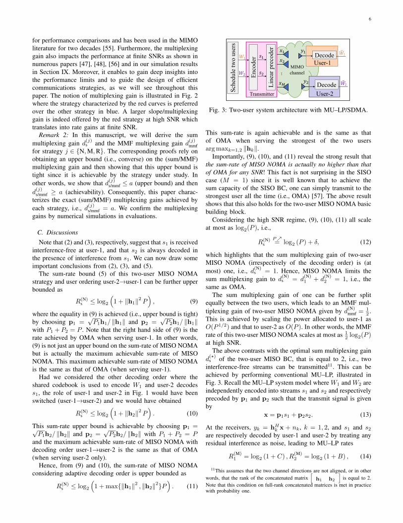
intended for user-1 and user-2, respectively.The transmitter adopts the so-called multi-antenna NOMA
or MISO NOMA strategy, illustrated in Fig. 1, that encodesone of the two messages using a codebook shared by bothusers4 so that it can be decoded and cancelled from thereceived signal at the co-scheduled user (following the same
3Throughout the paper, we will assume fully digital processing with Mantennas and M RF chains. This is standard in communication theoreticstudies but also in real multi-antenna deployments, even for massive mimowith sub 6GHz deployments (e.g. Ericsson AIR 6468). For millimeter-wavedeployments, it is plausible that future systems will be fully digital tooeventually [52].
4This is not an issue in modern systems since, for example, in an LTE/5GNR system, all codebooks are shared since all users use the same family ofmodulation and coding schemes (MCS) specified in the standard.
Fig. 1: Two-user system architecture with NOMA (decodingorder: user-2→user-1).
principle as superposition coding for the degraded BC). Con-sider W2 is encoded into s2 using the shared codebook andW1 is encoded into s1. The two streams are then linearlyprecoded by M × 1 precoders5 p1 and p2 and superposed atthe transmitter so that the transmit signal is given by
x = p1s1 + p2s2. (1)
Defining s = [s1, s2]T and assuming that E[ssH ] = I, theaverage transmit (sum) power constraint is written as P1 +P2 ≤ P where Pk = ‖pk‖2 with k = 1, 2.
The channel vector for user k is denoted by hk, and thereceived signal at user k can be written as yk = hHk x + nk,k = 1, 2, where nk ∼ CN (0, 1) is Additive White GaussianNoise (AWGN). We assume perfect CSIT and perfect ChannelState Information at the Receivers (CSIR).
At both users, stream s2 is decoded first into6 W2 by treatingthe interference from s1 as noise. Using SIC at user-1, W2 isre-encoded, precoded, and subtracted from the received signal,such that user-1 can decode its stream s1 into W1. Assumingproper Gaussian signaling and perfect SIC7, the achievablerates of the two streams with MISO NOMA are given by8
R(N)1 = log2
(1 +
∣∣hH1 p1
∣∣2) , (2)
R(N)2 = min (log2 (1 +A) , log2 (1 +B)) , (3)
where
A =
∣∣hH1 p2
∣∣21 +
∣∣hH1 p1
∣∣2 , B =
∣∣hH2 p2
∣∣21 +
∣∣hH2 p1
∣∣2 . (4)
In (3), log2 (1 +A) is the rate supportable by the channel ofuser-1 when user-1 decodes s2 and treats its own stream s1as noise. Similarly, log2 (1 +B) is the rate supportable by thechannel of user-2 when user-2 decodes its own stream s2 whiletreating stream s1 of user-1 as noise. The min in (3) is due
5The precoders p1 and p2 can be any vectors that satisfy the powerconstraint, though the best choice of precoders would depend on the objectivefunction.
6Though not expressed explicitly, W2 is receiver dependent since bothreceivers decode s2 and the same estimate is not necessarily obtained at bothreceivers. Hence, more rigorously, we could have written W2,k , k = 1, 2to refer to the estimate at user-k. For simplicity of presentation, we havenevertheless opted to drop the index k.
7Note there is no error in the SIC operation since the chosen rates areachievable under Gaussian signaling and infinite block length.
8Superscript (N) stands for NOMA. Similarly we will user (M) for MU–LP,(R) for Rate-Splitting, and ? for the information theoretic optimum.
5
to the fact that s2, though carrying message W2 intended touser-2, is decoded by both users and is therefore transmittedat a rate decodable by both users.
The most common performance metric of a multi-usersystem is the sum-rate. In this two-user MISO NOMA systemmodel, the sum-rate is defined as R(N)
s = R(N)1 +R
(N)2 and can
be upper bounded9 as
R(N)s ≤ log2
(1 +
∣∣hH1 p2
∣∣21 +
∣∣hH1 p1
∣∣2)
+ log2
(1 +
∣∣hH1 p1
∣∣2) ,= log2
(1 +
∣∣hH1 p2
∣∣2 +∣∣hH1 p1
∣∣2) . (5)
It is important to note that (5) can be interpreted as thesum-rate of a two-user multiple access channel (MAC) with asingle-antenna receiver. Indeed, user-1 acts as the receiver ofa two-user MAC whose effective SISO channels for both linksare given by hH1 p2 and hH1 p1, respectively. This observationwill be revisited in the next few sections, and will be shownvery helpful to explain the performance of multi-antennaNOMA.
A drawback of the sum-rate is that it does not capture ratefairness among the users. Another popular system performancemetric is the Max-Min Fair (MMF) rate or symmetric ratedefined as R(N)
mmf = mink=1,2R(N)k . The MMF metric provides
uniformly good QoS since it aims for maximizing the mini-mum rate among all users.
Throughout the manuscript, we will focus on the sum-rateand the MMF rate as two very different metrics to assess thesystem performance. We choose these two metrics as theyare commonly used in wireless networks, and in the NOMAliterature in particular (see, e.g., [20], [24], [30], [32], [33]for the sum-rate and [34], [35], [39], [53], [54] for the MMFrate). They are representative for two very different operationalregimes, with the former focusing on high system throughputand the latter on user fairness.
In the sequel, we introduce some useful definitions and thenmake some observations based on this two-user system model.
B. Definition of Multiplexing Gain
Throughout the paper, we will often refer to the multi-plexing gain to quantify how well a communication strategycan exploit the available spatial dimensions. We define themultiplexing gain, also referred to as Degrees-of-Freedom(DoF), of user-k achieved with communication strategy10 jas
d(j)k = lim
P→∞
R(j)k (P )
log2(P ), (6)
and the sum multiplexing gain as
d(j)s = limP→∞
R(j)s (P )
log2(P )=
K∑k=1
d(j)k , (7)
9This is an upper bound since when A < B, it is achieved with equality,and when B < A, log2(1+B) < log2(1+A) and it is a strict upper bound.
10Throughout this paper, j will be either N for NOMA, M for MU–LP,R for Rate-Splitting, or ? for the information theoretic optimum, i.e., j ∈{N, M, R, ?}.
5 10 15 20 25 30 35 40 45 500
5
10
15
20
25
30
35
SNR (dB)
Rate
(bps/
Hz)
DoF (multiplexing gain): slope of rate vs SNR
The larger the DoF,
the faster the rate
increases with SNR
K = = 4
K = = 2
red > blue
M
M
Fig. 2: Illustration of the notion of multiplexing gain/DoF.
where R(j)s =
∑Kk=1R
(j)k is the sum-rate. We also define the
MMF multiplexing gain as
d(j)mmf = lim
P→∞
R(j)mmf(P )
log2(P )= mink=1,...,K
d(j)k , (8)
where R(j)mmf = mink=1,...,K R
(j)k is the MMF rate.
The multiplexing gain d(j)k is a first-order approximation
of the rate of user-k at high SNR. d(j)k can be viewed asthe pre-log factor of the rate of user-k at high SNR andbe interpreted as the number or fraction of interference-freestream(s) that can be simultaneously communicated to user-k by employing communication strategy j. The larger d(j)k ,the faster the rate of user-k increases with the SNR. Hence,ideally a communication strategy should achieve the highestmultiplexing gain possible.
The sum multiplexing gain d(j)s is a first-order approxi-
mation of the sum-rate at high SNR and therefore the pre-log factor of the sum-rate and can be interpreted as thetotal number of interference-free data streams that can besimultaneously communicated to all K users by employingcommunication strategy j. In other words, R(j)
s scales asd(j)s log2(P )+δ where δ is a term that scales slowly with SNR
such that limP→∞δ
log2(P ) = 0 (e.g., O(1), O(log2(log2(P )))
or O(√
log2(P ))), and the larger d(j)s , the faster the sum-rateincreases with the SNR.
The MMF multiplexing gain d(j)mmf, also referred to as
symmetric multiplexing gain, corresponds to the maximummultiplexing gain that can be simultaneously achieved by allusers, and reflects the pre-log factor of the MMF rate at highSNR. In other words, R(j)
mmf scales as d(j)mmf log2(P ) + δ, andthe larger d(j)mmf, the faster the MMF rate increases with theSNR.
Remark 1: Much of the analysis and discussion in thispaper emphasizes the (sum and MMF) multiplexing gain as ametric to assess the capability of a strategy to exploit multipleantennas. As it becomes plausible from its definition, themultiplexing gain is an asymptotic metric valid in the limit ofhigh SNR, and hence, does not precisely reflect specific finite-SNR rates. Nevertheless, it provides firm theoretical grounds
6
for performance comparisons and has been used in the MIMOliterature for two decades [55]. Furthermore, the multiplexinggain also impacts the performance at finite SNRs as shown innumerous papers [47], [48], [56] and in our simulation resultsin Section IX. Moreover, it enables to gain deep insights intothe performance limits and to guide the design of efficientcommunications strategies, as we will see throughout thispaper. The notion of multiplexing gain is illustrated in Fig. 2where the strategy characterized by the red curves is preferredover the other strategy in blue. A larger slope/multiplexinggain is indeed offered by the red strategy at high SNR whichtranslates into rate gains at finite SNR.
Remark 2: In this manuscript, we will derive the summultiplexing gain d
(j)s and the MMF multiplexing gain d
(j)mmf
for strategy j ∈ {N,M,R}. The corresponding proofs rely onobtaining an upper bound (i.e., converse) on the (sum/MMF)multiplexing gain and then showing that this upper bound istight since it is achievable by the strategy under study. Inother words, we show that d(j)s/mmf ≤ a (upper bound) and thend(j)s/mmf ≥ a (achievability). Consequently, this paper charac-
terizes the exact (sum/MMF) multiplexing gains achieved byeach strategy, i.e., d(j)s/mmf = a. We confirm the multiplexinggains by numerical simulations in evaluations.
C. Discussions
Note that (2) and (3), respectively, suggest that s1 is receivedinterference-free at user-1, and that s2 is always decoded inthe presence of interference from s1. We can now draw someimportant conclusions from (2), (3), and (5).
The sum-rate bound (5) of this two-user MISO NOMAstrategy and user ordering user-2→user-1 can be further upperbounded as
R(N)s ≤ log2
(1 + ‖h1‖2 P
), (9)
where the equality in (9) is achieved (i.e., upper bound is tight)by choosing p1 =
√P1h1/ ‖h1‖ and p2 =
√P2h1/ ‖h1‖
with P1 + P2 = P . Note that the right hand side of (9) is therate achieved by OMA when serving user-1. In other words,(9) is not just an upper bound on the sum-rate of MISO NOMAbut is actually the maximum achievable sum-rate of MISONOMA. This maximum achievable sum-rate of MISO NOMAis the same as that of OMA (when serving user-1).
Had we considered the other decoding order where theshared codebook is used to encode W1 and user-2 decodess1, the role of user-1 and user-2 in Fig. 1 would have beenswitched (user-1→user-2) and we would have obtained
R(N)s ≤ log2
(1 + ‖h2‖2 P
). (10)
This sum-rate upper bound is achievable by choosing p1 =√P1h2/ ‖h2‖ and p2 =
√P2h2/ ‖h2‖ with P1 + P2 = P
and the maximum achievable sum-rate of MISO NOMA withdecoding order user-1→user-2 is the same as that of OMA(when serving user-2 only).
Hence, from (9) and (10), the sum-rate of MISO NOMAconsidering adaptive decoding order is upper bounded as
R(N)s ≤ log2
(1 + max{‖h1‖2 , ‖h2‖2}P
). (11)
Fig. 3: Two-user system architecture with MU–LP/SDMA.
This sum-rate is again achievable and is the same as thatof OMA when serving the strongest of the two usersarg maxk=1,2 ‖hk‖.
Importantly, (9), (10), and (11) reveal the strong result thatthe sum-rate of MISO NOMA is actually no higher than thatof OMA for any SNR! This fact is not surprising in the SISOcase (M = 1) since it is well known that to achieve thesum capacity of the SISO BC, one can simply transmit to thestrongest user all the time (i.e., OMA) [57]. The above resultshows that this also holds for the two-user MISO NOMA basicbuilding block.
Considering the high SNR regime, (9), (10), (11) all scaleat most as log2(P ), i.e.,
R(N)s
P↗= log2 (P ) + δ, (12)
which highlights that the sum multiplexing gain of two-userMISO NOMA (irrespectively of the decoding order) is (atmost) one, i.e., d(N)
s = 1. Hence, MISO NOMA limits thesum multiplexing gain to d
(N)s = d
(N)1 + d
(N)2 = 1, i.e., the
same as OMA.The sum multiplexing gain of one can be further split
equally between the two users, which leads to an MMF mul-tiplexing gain of two-user MISO NOMA given by d(N)
mmf = 12 .
This is achieved by scaling the power allocated to user-1 asO(P 1/2) and that to user-2 as O(P ). In other words, the MMFrate of this two-user MISO NOMA scales at most as 1
2 log2(P )at high SNR.
The above contrasts with the optimal sum multiplexing gaind(?)s of the two-user MISO BC, that is equal to 2, i.e., two
interference-free streams can be transmitted11. This can beachieved by performing conventional MU–LP, illustrated inFig. 3. Recall the MU–LP system model where W1 and W2 areindependently encoded into streams s1 and s2 and respectivelyprecoded by p1 and p2 such that the transmit signal is givenby
x = p1s1 + p2s2. (13)
At the receivers, yk = hHk x + nk, k = 1, 2, and s1 and s2are respectively decoded by user-1 and user-2 by treating anyresidual interference as noise, leading to MU–LP rates
R(M)1 = log2 (1 + C) , R
(M)2 = log2 (1 +B) , (14)
11This assumes that the two channel directions are not aligned, or in otherwords, that the rank of the concatenated matrix
[h1 h2
]is equal to 2.
Note that this condition on full-rank concatenated matrices is met in practicewith probability one.
7
with
C =
∣∣hH1 p1
∣∣21 +
∣∣hH1 p2
∣∣2 , (15)
and B as specified in (4). It is then indeed sufficient12 totransmit two streams using uniform power allocation and Zero-Forcing Beamforming (ZFBF), so that hH1 p2 = hH2 p1 = 0,to reap the sum multiplexing gain d
(M)s = d
(?)s = 2 and
the MMF multiplexing gain d(M)mmf = d
(?)mmf = 1 (i.e., each
user gets one full interference-free stream). Indeed, with MU–LP, the sum-rate scales as 2 log2(P ) and the MMF rate aslog2(P ) at high SNR [58]–[60]. Such sum-rate and MMF ratewould always strictly outperform that of NOMA (and OMA)at high SNR. Since both OMA and NOMA achieve only halfthe (sum/MMF) multiplexing gain of MU–LP in the two-userMISO BC considered, it is not clear whether (and under whatconditions) multi-antenna NOMA can outperform MU–LPand other forms of multi-user multi-antenna communicationstrategies, and if it does, whether multi-antenna NOMA isworth the associated increase in receiver complexity. Theabove discussion exposes some weaknesses of multi-antennaNOMA and highlights the uncertainty regarding the potentialbenefits of multi-antenna NOMA. Hence, in the followingsections, we derive the multiplexing gains of generalized K-user multi-antenna NOMA, so as to better assess its potential.
Remark 3: It appears from (1) and (13) that the transmitsignal vectors for 2-user MISO NOMA and 2-user MU–LPare the same, therefore giving the impression that NOMA isthe same as MU–LP. This is obviously incorrect. Recall themajor differences in the encoding and the decoding of NOMAand MU–LP:• Encoding: In NOMA, W1 is encoded into s1 and W2 is
encoded into s2 at a rate such that s2 is decodable byboth users, while W1 and W2 are independently encodedinto streams s1 and s2 in MU–LP.
• Decoding: User-1 decodes s1 and s2 and user-2 decodess2 by treating s1 as noise in NOMA while s1 is decodedby user-1 by treating s2 as noise and s2 is decoded byuser-2 by treating s1 as noise in MU–LP.
Consequently the rate expressions (2), (3) and (14) are differ-ent, which therefore suggests that the best pair of precodersp1 and p2 that maximizes a given objective function (e.g.,sum-rate, MMF rate) would be different for NOMA and MU–LP. Choosing p1 and p2 according to ZFBF would commonlywork reasonably well for MU–LP but would lead to R(N)
2 = 0in (3) for NOMA. Nevertheless, the above discussion onmultiplexing gain loss of MISO NOMA always holds, evenin the event where MISO NOMA is implemented with thebest choice of precoders, since the above analysis for MISONOMA is based on an upper bound.
III. K-USER MISO NOMA WITH PERFECT CSIT
We now study K-user MISO NOMA relying on perfectCSIT and derive the sum and MMF multiplexing gains.
12More complicated precoders (or communication strategies like non-linearprecoding and DPC) can be used to enhance the rate performance, but thesum and MMF multiplexing gains will not improve in this 2-user setting.
A. MISO NOMA System Model
We consider a K-user MISO NOMA scenario where asingle transmitter equipped with M transmit antennas servesK single-antenna users indexed by K = {1, . . . ,K}. The Kusers are grouped into 1 ≤ G < K groups13 with groupsindexed by G = {1, . . . , G}. There are g users per group, i.e.,we therefore assume for simplicity that K = gG. Users ingroup i are indexed by Ki = {ig − g + 1, . . . , ig}. Hence,K =
⋃i∈G Ki and |Ki| = g. Without loss of generality, we
assume that users 1, g+1, 2g+1, . . . , K−g+1 are the “strongusers”14 respectively in group 1 to G, and perform g−1 layersof SIC to fully decode the messages (and therefore removeinterference) from the other g−1 users within the same group.Similarly, the second user in each group (i.e., ig − g + 2 ingroup i) performs g−2 layers of SIC to fully decode messagesfrom other g − 2 users within the same group, and so on.The two most popular MISO NOMA strategies employ eitherG = 1 [20]–[23] or G = K/2 [26]–[31] but we keep here thescenario general for any value of 1 ≤ G < K. The generalarchitecture of MISO NOMA is illustrated in Fig. 4. The two-user building block in Section II can be viewed as a particularinstance with K = 2 and G = 1.
At the transmitter, the messages W1 to WK intended foruser-1 to user-K, respectively, are encoded into s1 to sK .However, some of the messages in each group have to beencoded using codebooks shared by a subset of the users inthat group so that they can be decoded and cancelled fromthe received signals at the co-scheduled users in that group.In particular, taking group 1 as an example, W2 to Wg areencoded using codebooks shared with user-1 such that user-1can decode all of these g − 1 messages. After encoding, theK streams are linearly precoded by precoders15 p1 to pK ,where pk ∈ CM is the precoder of sk, and superposed at thetransmitter. The resulting transmit signal is
x =
K∑k=1
pksk. (16)
Defining s = [s1, ..., sK ]T and assuming that E[ssH ] = I, theaverage transmit power constraint is written as
∑Kk=1 Pk ≤ P ,
where Pk = ‖pk‖2.
13 Note that 1 ≤ G < K is a widely considered option for MISO NOMAin which there exists (at least) one user decoding the message of (at least)one another user in each group. Importantly, G = K corresponds to MU–LPas per Section VI and is not a MISO NOMA scheme since all K messagesare independently encoded into K streams and residual interference is treatedas noise at the receivers, i.e., there is no shared codebook and users thereforedo not decode the messages of other users.
14“Strong users" here refer to the users who decode the messages of otherusers in a group. Given the nondegraded nature of the multi-antenna BC, thestrong users do not necessarily have to be the users with the largest channelvector norm. The multiplexing gain analysis is general and holds for anyordering. Nevertheless, following [22], [23], we consider in the simulationsection the decoding order in each group to be the ascending order of users’channel strength such that “strong users" refer to the users with the largestchannel vector norm respectively in group 1 to G.
15Further constraints can be imposed on the precoder design such thatthe same precoder is used for all users in the same group. This constraintwould however further reduce the optimization space and therefore the rateperformance.
8
Fig. 4: K-user system architecture with MISO NOMA (con-taining G user groups and g users within each group).
At the receiver side, the signal received at user-k is yk =hHk x + nk, k ∈ K, where hk is the channel vector16 ofuser-k, perfectly known at the transmitter and that user, andnk ∼ CN (0, 1) is the AWGN. By employing SIC, user-j ingroup i (i.e., j ∈ Ki) decodes the messages of users-{k | k ≥j, k ∈ Ki} within the same user group in a descending orderof the user index while treating the interference from users indifferent groups as noise. Under the assumption of Gaussiansignaling and perfect SIC, the rate at user-j, j ∈ Ki, to decodethe message of user-k, k ≥ j, k ∈ Ki, is given by
Rj,k = log2
(1 +
|hHj pk|2
I(in)j,k + I
(ou)j,k + 1
), (17)
where
I(in)j,k =
∑m<k,m∈Ki
|hHj pm|2, I(ou)j,k =∑
l 6=i,l∈G
∑m∈Kl
|hHj pm|2
(18)are the intra-group interference and inter-group interferencereceived at user-k, respectively. As the message of user-k, k ∈Ki, has to be decoded by users-{j|j ≤ k, j ∈ Ki}, to ensuredecodability, the rate of user-k should not exceed
R(N)k = min
j≤k,j∈KiRj,k. (19)
In the next subsection, we study the sum multiplexing gainand the MMF multiplexing gain of K-user MISO NOMA.
B. Multiplexing Gains
The following proposition provides the sum multiplexinggain of MISO NOMA for perfect CSIT.
Proposition 1: The sum multiplexing gain of K-user MISONOMA with M transmit antennas, G groups of g = K/G
users, and perfect CSIT is d(N)s = min (M,G).
Proof: The proof is obtained by showing that an upperbound on the sum multiplexing gain is achievable. The upperbound is obtained by applying the MAC argument (used in
16The rank of matrix[
h1 . . . hK
]is assumed equal to
min{M,K} for simplicity. Note that this condition is met in practice and ismotivated by practical deployments. Ranks strictly smaller than min{M,K}(due to, e.g., aligned channels) would not occur (zero probability) in realwireless deployments with fading channels and are therefore not of practicalinterest.
(5)) to the strong user in each group and noticing that thesum-rate in groups 1 to G is upper bounded as
g∑k=1
R(N)k ≤ log2
(1 +
g∑k=1
∣∣hH1 pk∣∣2) , (20)
2g∑k=g+1
R(N)k ≤ log2
1 +
2g∑k=g+1
∣∣hHg+1pk∣∣2 , (21)
...K∑
k=K−g+1
R(N)k ≤ log2
1 +
K∑k=K−g+1
∣∣hHK−g+1pk∣∣2 .
(22)
Note that the left-hand sides of (20), (21), and (22) refer tothe sum of the rates of the messages in group 1, 2, and G,respectively, but can also be viewed as the total rate to bedecoded by user 1, g + 1, and K − g + 1 (since those usersdecode all the messages in their respective group). We nownotice that the right-hand sides of (20), (21), and (22) scale aslog2(P )+δ for large P (following the same argument as in thetwo-user case). This implies that each group i achieves at mosta (group) sum multiplexing gain d
(N)s,i =
∑igk=ig−g+1 d
(N)k of
1, i.e., at most one interference-free stream can be transmittedto each group. Summing up all inequalities, we obtain in thelimit of large P that
R(N)s =
K∑k=1
R(N)k
P↗≤ G log2(P ) + δ, (23)
which shows that d(N)s =
∑Gi=1 d
(N)s,i ≤ G. Additionally, since
d(N)s ≤ d?s = min (M,K), we have d(N)
s ≤ min (M,G).The achievability part shows that d(N)
s ≥ min (M,G). Tothis end, it is indeed sufficient to perform ZFBF and transmitmin (M,G) interference-free streams to min (M,G) of the G“strong users”. Combining the upper bound and achievabilityleads to the conclusion that d(N)
s = min (M,G). 2
The following result derives the MMF multiplexing gain ofMISO NOMA with perfect CSIT.
Proposition 2: The MMF multiplexing gain of K-userMISO NOMA with M transmit antennas, G groups of g =K/G users and perfect CSIT is
d(N)mmf =
{1g , M ≥ K − g + 1,
0, M < K − g + 1.(24)
For G = 1, i.e., g = K, d(N)mmf = 1
K .Proof: Let us first consider M ≥ K − g + 1. The MMF
multiplexing gain is always upperbounded by ignoring theinter-group interference, i.e., the G groups are non-interfering.Following again the MAC argument, the sum multiplexinggain of one in each group can then be further split equallyamong the g users, which leads to an upper bound on theMMF multiplexing gain of 1
g . Achievability is simply obtainedby designing the precoders using ZFBF to eliminate all inter-group interference, and allocating the power similarly toSubsection II-C. Indeed let us consider group 1 for simplicity,
9
and allocate the power to user k = 1, . . . , g as O(P k/g). Thisleads to an SINR for user-k scaling as O(P 1/g) and to anachievable MMF multiplexing gain of 1
g . For G = 1, one cansimply allocate the power to user k = 1, . . . ,K as O(P k/K),which leads to an achievable MMF multiplexing gain of 1
K .Let us now consider M < K−g+1. Take M = K−g (any
smaller M cannot improve the multiplexing gain). Precoderpk of any user-k can be made orthogonal to the channel of atmost K − g − 1 co-scheduled users and will therefore causeinterference to at least one user in another group. As a result,the MMF multiplexing gain collapses to 0. 2
Remark 4: For the MMF multiplexing gain analysis, itshould be noted that we consider one-shot transmissionschemes with no time-sharing between strategies. This issuitable for systems with rigid scheduling and/or tight latencyconstraints, and also allows for simpler designs. This assump-tion is also commonly used in the NOMA literature [34], [35],[39], [53], [54].
IV. K-USER MISO NOMA WITH IMPERFECT CSIT
We now go one step further and extend the multiplexinggain analysis to the imperfect CSIT setting. The results inthis section therefore generalize the results in the previoussection (with perfect CSIT being a particular case of imperfectCSIT). In this section, the achievable rates are defined inthe ergodic sense in a standard Shannon theoretic fashion,and the corresponding sum and MMF mutiplexing gains aredefined similarly to Subsection II-B using ergodic rates. Wefirst introduce the CSIT error model before deriving themultiplexing gains of MISO NOMA relying on imperfectCSIT.
A. CSIT Error Model
For each user, the transmitter acquires an imperfect estimateof the channel vector hk, denoted as hk. The CSIT imperfec-tion is modelled by
hk = hk + hk, (25)
where hk denotes the corresponding channel estimation er-ror at the transmitter. For compactness, we define H =[h1 . . .hK ], H = [h1 . . . hK ], and H = [h1 . . . hK ], whichimplies H = H+H. The joint fading process is characterizedby the joint distribution fH,H
(H, H
)of {H, H}, assumed to
be stationary and ergodic . The joint distribution fH,H(H, H
)is continuous and known to the transmitter. The ergodicrates capture the long-term performance over a long sequenceof channel uses {H, H} spanning almost all possible jointchannel states.
For each user-k, we define the average channel (power) gainas Γk = E
{‖hk‖2
}. Similarly, we define Γk = E
{∥∥hk∥∥2}and Γk = E
{∥∥hk∥∥2}. For many CSIT acquisition mechanisms[61], hk and hk are uncorrelated according to the orthogonal-ity principle [62]. By further assuming that hk and hk havezero means, we have Γk = Γk + Γk, based on which wecan write Γk = (1 − σ2
e,k)Γk and Γk = σ2e,kΓk for some
σ2e,k ∈ [0, 1]. Note that σ2
e,k is the normalized estimation
error variance for user-k’s CSIT, e.g., σ2e,k = 1 corresponds
to no instantaneous CSIT, while σ2e,k = 0 represents perfect
instantaneous CSIT.For simplicity, we assume identical normalized CSIT error
variances for all users, i.e., σ2e,k = σ2
e for all k = 1, . . . ,K.To facilitate the multiplexing gain analysis, we assume thatσ2e scales with SNR as σ2
e = P−α for some CSIT qualityparameter α ∈ [0,∞) [46], [47], [60], [63], [64]. This isa convenient and tractable model extensively used in theinformation theoretic literature that allows us to assess theperformance of the system in a wide range of CSIT qualityconditions. Indeed, the larger α, the faster the CSIT errordecreases with the SNR. The two extreme cases, α = 0 andα =∞, correspond to no or constant CSIT (i.e., that does notscale or improve with SNR) and perfect CSIT, respectively. Asfar as the multiplexing gain analysis is concerned, however,we may truncate the CSIT quality parameter as α ∈ [0, 1],where α = 1 amounts to perfect CSIT in the multiplexinggain sense. The regime α ∈ (0, 1) corresponds to partial CSIT,resulting from imperfect CSI acquisition. The CSIT qualityα can be interpreted in many different ways, but a plausibleinterpretation of α is related to the number of feedback bits,where α = 0 corresponds to a fixed number of feedbackbits for all SNRs, α = ∞ corresponds to an infinite numberof feedback bits, and 0 < α < ∞ reflects how quicklythe number of feedback bits increases with the SNR. As areference, a system like 4G and 5G use α = 0 when limitedfeedback (or codebook-based feedback) is used to report theCSI, since the number of feedback bits is constant and doesnot scale with SNR, e.g., 4 bits of CSI feedback in 4G LTEfor M = 4.
B. Multiplexing GainsThe following result quantifies the sum multiplexing gain
of MISO NOMA for imperfect CSIT.Proposition 3: The sum multiplexing gain of K-user
MISO NOMA with M transmit antennas, G groups of g =
K/G users, and CSIT quality 0 ≤ α ≤ 1 is d(N)s =
max (1,min (M,G)α).Proof: Similar to the proof of Proposition 1, let us look at
the G strong users since they have to decode all messages. Werecall that d(N)
s,i =∑igk=ig−g+1 d
(N)k reflects the multiplexing
gain of the total rate to be decoded by the strong user ig −g+ 1 in group i as a consequence that this user decodes all gmessages in group i. Making use of the results of MU–LP inthe G-user MISO BC with imperfect CSIT [47]17, we obtaind(N)s =
∑Gi=1 d
(N)s,i =
∑Kk=1 d
(N)k ≤ max (1,min (M,G)α).
The achievability part shows that d(N)s ≥
max (1,min (M,G)α). It is indeed sufficient to performZFBF and transmit min (M,G) streams, each at a powerlevel of Pα/min (M,G), to min (M,G) of the G “strongusers”. If min (M,G)α < 1, one can simply transmit a singlestream (i.e., perform OMA) and reap a sum multiplexing gainof 1. Combining the upper bound and achievability leads tothe conclusion that we have d(N)
s = max (1,min (M,G)α).2
17See also Proposition 7.
10
For α = 1 (perfect CSIT from a multiplexing gain perspec-tive), Proposition 3 boils down to the perfect CSIT result inProposition 1.
The following proposition provides the MMF multiplexinggain of MISO NOMA with imperfect CSIT.
Proposition 4: The MMF multiplexing gain of K-userMISO NOMA with M transmit antennas, G groups of g =K/G users, and CSIT quality 0 ≤ α ≤ 1 is
d(N)mmf =
αg , G > 1 andM ≥ K − g + 1,
0, G > 1 andM < K − g + 1,1K , G = 1.
(26)
The proof is relegated to Appendix A.It is interesting to note that the sensitivity of the multiplex-
ing gain of MISO NOMA to the CSIT quality α is differentfor G > 1 and G = 1. Indeed the sum and MMF multiplexinggains of MISO NOMA with G > 1 decay as α decreases,while the multiplexing gains of MISO NOMA with G = 1are not affected by α. This can be interpreted in two differentways. On the one hand, this suggests that MISO NOMAG = 1 is inherently robust to CSIT imperfection since themultiplexing gains are not affected by α < 1. On the otherhand, this also reveals that MISO NOMA with G = 1 is unableto exploit the presence of CSIT since its multiplexing gainsare the same as in the absence of CSIT (α = 0).
V. MIMO NOMA
We now consider multi-antenna receivers and extend thetwo-user MISO NOMA toy example of Section II to a two-user MIMO NOMA setting with perfect CSIT.
We consider a two-user MIMO BC, consisting of onetransmitter with M antennas and two users equipped with Nantennas each. The signal vector yk ∈ CN×1 received at user-k is written as yk = HH
k x + nk, where Hk ∈ CM×N isthe channel matrix18 of user-k and nk is the AWGN vectorat user-k. Following the NOMA principle, the transmit signalvector x is generated such that the messages intended for user-2 are encoded using a shared codebook so as to be decodableby user-1. Defining the transmit covariance matrix of user-k as Qk subject to the average transmit power constraintTr(Q1) + Tr(Q2) ≤ P , and assuming Gaussian signaling, theachievable rates of both users are given by
R(N)1 =log2 det
(IN + HH
1 Q1H1
), (27)
R(N)2 =min (log2 det (IN + R1) , log2 det (IN + R2)) , (28)
where Rk = HHk Q2Hk
(IN + HH
k Q1Hk
)−1, k = 1, 2.
The sum-rate R(N)s of the two-user MIMO NOMA can then
be bounded as
R(N)s ≤ log2 det (IN + R1) + log2 det
(IN + HH
1 Q1H1
),
= log2 det(IN + HH
1 Q1H1 + HH1 Q2H1
). (29)
18We assume for simplicity that Hk is full rank.
The sum-rate bound achieved with this two-user MIMONOMA strategy can be further upper bounded as
R(N)s ≤ log2 det
(IN + HH
1 Q?1H1
),
P↗= min (M,N) log2 (P ) +O(1), (30)
where Q?1 refers to the optimal covariance matrix for user-1
in a single-user (OMA) setup with Tr(Q1) = P , i.e., obtainedby transmitting along the dominant eigenvector of H1H
H1 and
allocating power P according to the water-filling solution.Similarly to the MISO case, the other decoding order
could also be considered and a similar analysis can be ob-tained. Ultimately, the sum-rate of MIMO NOMA (irrespectiveof the decoding order) is actually no larger than that ofOMA at any SNR. The sum multiplexing gain is limited byd(N)s = min (M,N), which is smaller than the optimal sum
multiplexing gain of the MIMO BC d(?)s = min (M, 2N),
achieved by conventional MU-MIMO/MU–LP precoding [59].This analysis highlights that MIMO NOMA incurs a summultiplexing loss whenever N < M , i.e., when the num-ber of receive antennas at each device is smaller than thenumber of transmit antennas at the base station, which wouldoccur in most realistic and practical MIMO deployments.Similarly, the MMF multiplexing gain is also affected sinced(N)mmf = min (M,N) /2, obtained by equally splitting the sum
multiplexing gain amongst the two users, which again incurs aloss whenever N < M . Taking for instance M = 6 and N = 4
leads to d(N)s = 4 and d
(N)mmf = 2, though one could easily
transmit using multi-user MIMO (e.g., block diagonalization[65], [66]) 6 interference-free streams with 3 streams per user.
Recall that the above MIMO NOMA scheme and analysiswere based on the principle that one user is forced to fullydecode the messages of the other co-scheduled user. Never-theless other MIMO NOMA schemes have recently appearedthat may not satisfy this definition of MIMO NOMA and maytherefore achieve different (and hopefully superior) sum andMMF multiplexing gains [67], [68].
VI. BASELINE SCHEME I:CONVENTIONAL MULTI-USER LINEAR PRECODING
The first baseline to assess the performance of multi-antennaNOMA is conventional Multi-User Linear Precoding. In thesequel, we recall the multiplexing gains achieved by MU–LP.
A. MU–LP System Model
Following Subsection III-A, we consider a K-user MISOBC with one transmitter equipped with M transmit antennasand K single-antenna users. As per Fig. 5, the messagesW1, . . . ,WK respectively for user-1 to user-K are indepen-dently encoded into s1 to sK , which are then mapped to thetransmit antennas through precoders p1, . . . ,pK . The resultingtransmit signal is x =
∑Kk=1 pksk.
The signal received at user-k is yk = hHk x+nk with nk ∼CN (0, 1). Each user-k directly decodes the intended messageWk by treating the interference from the other users as noise.
11
Fig. 5: K-user system architecture with MU–LP. Receiverarchitecture is illustrated for user-k though the same appliesto other users, i.e., all K users are equipped with a decoderthat maps the received signal into an estimated message bytreating residual interference as noise.
Under the assumption of Gaussian signaling, the rate of user-kfor k ∈ K is given by
R(M)k = log2
(1 +
∣∣hHk pk∣∣2
1 +∑q 6=k
∣∣hHk pq∣∣2). (31)
The sum-rate of MU–LP is therefore R(M)s =
∑Kk=1R
(M)k ,
and the MMF rate of MU–LP is given as R(M)mmf =
mink=1,...,K R(M)k .
B. Multiplexing Gains with Perfect CSIT
We recall the sum multiplexing gain and the MMF multi-plexing gain of MU–LP with perfect CSIT from [59] and [56],respectively.
Proposition 5: The sum multiplexing gain of K-user MU–LP with M transmit antennas and perfect CSIT is d(M)
s =min (M,K).
This result19 is simply achieved by choosing the MU–LP precoders based on ZFBF and transmitting min (M,K)interference-free streams. Note that min (M,K) is also theoptimal20 sum multiplexing gain of the K-user MISO BC21
[59]. In other words, d(M)s = d
(?)s = min (M,K).
Proposition 6: The MMF multiplexing gain of the K-userMU–LP with M transmit antennas and perfect CSIT is
d(M)mmf =
{1, M ≥ K,0, M < K.
(32)
When M ≥ K, ZFBF can be used to fully eliminateinterference. On the other hand, for M < K interferencecannot be eliminated anymore and d
(M)mmf collapses, therefore
leading to a rate saturation at high SNR.
19It is implicitly assumed here that the coherence block is much larger thanmin(M,K) such that the resource needed to estimate the channel vanishes.
20This is easily proved by showing that an upper bound on the sum multi-plexing gain is equal to min (M,K), which is the same as the lower boundachieved by MU–LP. The upper bound is obtained by noticing that enablingfull cooperation among receivers does not decrease the sum multiplexing gainand leads to an effective point-to-point MIMO channel with M transmit andK receive antennas, which has a sum multiplexing gain of min (M,K).
21More generally, in MIMO BC, d(M)s = d
(?)s = min (M,KN) [59].
C. Multiplexing Gains with Imperfect CSIT
We use the CSIT error model introduced in SubsectionIV-A. We recall the sum multiplexing gain and the MMFmultiplexing gain of MU–LP with imperfect CSIT from [47]and [48], [69], respectively.
Proposition 7: The sum multiplexing gain of the K-userMU–LP with M transmit antennas and CSIT quality 0 ≤ α ≤1 is d(M)
s = max (1,min (M,K)α).This result is simply achieved by choosing the MU–LP pre-
coders based on ZFBF and transmitting min (M,K) streams,each with power level Pα/min (M,K). This enables eachstream to reap a multiplexing gain of α and therefore a summultiplexing gain of min (M,K)α. If min (M,K)α < 1, onecan simply transmit a single stream (i.e., perform OMA) andreap a sum multiplexing gain of 1.
Comparing Propositions 5 and 7, we note that imperfectCSIT leads to a reduction of the sum multiplexing gain. Forα = 1 (perfect CSIT in a multiplexing gain sense), Proposition7 matches Proposition 5. Importantly, in contrast to the K-user MISO BC with perfect CSIT setting where MU–LPachieves the information theoretic optimal sum multiplexinggain d(M)
s = d(?)s , in the imperfect CSIT setting, MU–LP does
not achieve the information theoretic optimal sum multiplexinggain [47], [63].
Proposition 8: The MMF multiplexing gain of the K-userMU–LP with M transmit antennas and CSIT quality 0 ≤ α ≤1 is
d(M)mmf =
{α, M ≥ K,0, M < K.
(33)
This is achieved by performing ZFBF when M ≥ K. WhenM < K, rate saturation occurs (similarly to the perfect CSITsetting).
VII. BASELINE SCHEME II: RATE-SPLITTING
The second baseline to assess multi-antenna NOMA perfor-mance is Rate-Splitting Multiple Access (RSMA), based onmulti-antenna Rate-Splitting (RS), for the multi-antenna BC[45]–[51]. This approach leverages and extends the conceptof RS, originally developed in [70] for the two-user single-antenna interference channel, to design multi-antenna non-orthogonal transmission strategies for the multi-antenna BC.
A. Rate-Splitting System Model
We consider again a MISO BC consisting of one transmitterwith M antennas and K single-antenna users. As per Fig.6, the architecture relies on rate-splitting of messages W1 toWK intended for user-1 to user-K, respectively. To that end,message Wk of user-k is split into a common part Wc,k anda private part Wp,k. The common parts Wc,1, . . . ,Wc,K of allusers are combined into the common message Wc, which isencoded into the common stream sc using a codebook sharedby all users. Hence, sc is a common stream required to bedecoded by all users and contains parts of messages W1 toWK intended for user-1 to user-K, respectively. The privateparts Wp,1, . . . ,Wp,K , respectively containing the remainingparts of messages W1 to WK , are independently encoded into
12
Fig. 6: K-user system architecture with 1-layer rate-splitting.Receiver architecture is illustrated for user-k though the sameapplies to other users.
private stream s1 for user-1 to sK for user-K. From the Kmessages, K + 1 streams sc, s1, . . . , sK are therefore created.The streams are linearly precoded such that the transmit signalis given by
x = pcsc +
K∑k=1
pksk. (34)
Defining s = [sc, s1, . . . , sK ]T and assuming that E[ssH ] =I, the average transmit power constraint is written as Pc +∑Kk=1 Pk ≤ P , where Pc = ‖pc‖2 and Pk = ‖pk‖2.At each user-k, the common stream sc is first decoded
into Wc by treating the interference from the private streamsas noise. Using SIC, Wc is re-encoded, precoded, and sub-tracted from the received signal, such that user-k can decodeits private stream sk into Wp,k by treating the remaininginterference from the other private stream as noise. User-kreconstructs the original message by extracting Wc,k from Wc,and combining Wc,k with Wp,k into Wk. Assuming properGaussian signaling, the rate of the common stream is givenby
Rc = mink=1,...,K
log2
(1 +
∣∣hHk pc
∣∣21 +
∑Kq=1
∣∣hHk pq∣∣2). (35)
Assuming perfect SIC, the rates of the private streams areobtained as
Rk = log2
(1 +
∣∣hHk pk∣∣2
1 +∑q 6=k
∣∣hHk pq∣∣2). (36)
The rate of user-k is given by Rk+Rc,k where Rc,k is the rateof the common part of the kth user’s message, i.e., Wc,k, andsatisfies
∑Kk=1Rc,k = Rc. The sum-rate is therefore simply
written as R(R)s =
∑Kk=1(Rk + Rc,k) = Rc +
∑Kk=1Rk, and
the MMF rate is written as R(R)mmf = mink=1,...,K Rk +Rc,k.
The above RS architecture is called 1-layer RS since it onlyrelies on a single common stream and a single layer of SICat each user as illustrated in Fig. 6.
B. Multiplexing Gains with Perfect CSIT
We here summarize the sum and MMF multiplexing gainsachieved by 1-layer RS with perfect CSIT.
Proposition 9: The sum multiplexing gain of K-user 1-layerRS with M transmit antennas and perfect CSIT is d(R)
s =min (M,K).
Proof: Since MU–LP is a subscheme of 1-layer RS22, it issufficient23 to design the private precoders using ZFBF andallocate zero power to the common stream at high SNR. Notethat d(R)
s = d(M)s = d
(?)s = min (M,K). 2
Proposition 10: The MMF multiplexing gain of the K-user1-layer RS with M transmit antennas and perfect CSIT is
d(R)mmf =
{1, M ≥ K
11+K−M , M < K.
(37)
The MMF multiplexing gain of 1-layer RS was derived andproved in [56]24, under the same assumption as in Remark 4.Readers are referred to [56] for more details of the proof ofProposition 10.
C. Multiplexing Gains with Imperfect CSIT
Again, we use the CSIT error model introduced in Subsec-tion IV-A. We recall the sum multiplexing gain of RS withimperfect CSIT from [47].
Proposition 11: The sum multiplexing gain of K-user 1-layer RS with M transmit antennas and CSIT quality 0 ≤α ≤ 1 is d(R)
s = 1 + (min (M,K)− 1)α.
Achievability of d(R)s in Proposition 11 is obtained by using
random precoding to design pc with power level Pc = O(P ),transmitting min(M,K) private streams and using ZFBF todesign the precoders of those min(M,K) private streams,each with power level Pk = O(Pα). From the SINR expres-sions at the right-hand side of (35), it follows that the receivedSINR of the common stream at each user scales as O(P 1−α),leading to the multiplexing gain of 1 − α achieved by thecommon stream sc. By performing ZFBF, the transmittertransmits min (M,K) interference-free private streams. Thereceived SINR of each private stream scales as O(Pα) leadingto multiplexing gain α. Hence, we obtain the sum multiplexinggain of 1 + (min (M,K)− 1)α.
Importantly, for the underloaded regime M ≥ K, 1-layerRS achieves the information theoretic optimal sum multiplex-ing gain d
(M)s = d
(?)s in the imperfect CSIT setting [47],
[63]. Hence, 1-layer RS attains the optimal sum multiplexinggain for both perfect CSIT and imperfect CSIT (underloadedregime). Actually, for M ≥ K, 1-layer RS is optimal, achiev-ing the maximum multiplexing gain region of the underloaded
22By allocating no power to the common stream, 1-layer RS boils down toMU-LP.
23More complicated precoders for both the common and private streamscan be used to enhance the rate performance, but the multiplexing gain willnot improve.
24The MMF multiplexing gain derived in [56] considers a more complexscenario involving the simultaneous transmission of distinct messages tomultiple multicast groups (each message is intended for a group of users),known as multigroup multicasting. By considering the special case wherethere is a single user per group, we obtain the MMF multiplexing gain of1-layer RS in this section.
13
K-user MISO BC25 with imperfect CSIT [71], [72].This optimality of RS (including 1-layer RS), shown
through multiplexing gain analysis, is very significant sinceit implies that one cannot find any other scheme achieving abetter multiplexing gain region in the multi-antenna BC. Asa consequence of this optimality, MU–LP and multi-antennaNOMA will always incur a multiplexing gain loss or at bestwill achieve the same multiplexing gain as RS for both perfectand imperfect CSIT.
Proposition 12: The MMF multiplexing gain of K-user 1-layer RS with M transmit antennas and CSIT quality 0 ≤ α ≤1 is
d(R)mmf =
1+(K−1)α
K , M ≥ K1+(M−1)α
K , M < K and α ≤ 11+K−M
11+K−M , M < K and α > 1
1+K−M .
(38)
The MMF multiplexing gain of 1-layer RS with imperfectCSIT was derived in [69] (by considering the specific casewhere there is a single user per group), under the sameassumption as in Remark 4. Readers are referred to [69] formore details of the proof of Proposition 12.
This highlights that when M < K, the CSIT qualityα can be reduced to 1
1+K−M without impacting the MMFmultiplexing gain of 1-layer RS.
Following our discussion of Proposition 11, when M ≥ K,the respective multiplexing gains of the common and eachprivate streams are 1 − α and α. The MMF multiplexinggain when M ≥ K is achieved by evenly sharing thecommon stream among users and is the sum of the evenlyallocated multiplexing gain of the common stream 1−α
K and themultiplexing gain of one private stream α, yielding 1+(K−1)α
K .When M < K, the achievability is obtained by parti-
tioning users into two subsets K1 and K2 with set sizes of|K1| = M and |K2| = K − M . Users in K1 are servedvia the common and private streams while users in K2 areserved using the common stream only. Random precodingand ZFBF are respectively used for the common stream andthe private streams with power allocation Pc = O(P ) andPk = O(P β),∀k ∈ K1. It may be readily shown that therespective multiplexing gains of the common stream and eachprivate stream are given by 1−β and min{α, β}, respectively.By further introducing a fraction z ∈ [0, 1] to specify thefraction of the rate of the common stream allocated to theusers in the two subsets, we obtain that the respective summultiplexing gains of the common stream for the users in K1
and K2 are z(1−β) and (1−z)(1−β), respectively. By equallydividing the multiplexing gain of the common stream between
25The optimality of RS is not limited to MISO BC but also extends toMIMO BC. Indeed, a more complicated form of RS is multiplexing gainregion-optimal for the two-user MIMO BC with imperfect CSIT in the generalcase of an asymmetric number of receive antennas [73], [74]. Following [73],in the symmetric MIMO setting with M ≥ KN , the system model of RS canbe extended as in [75] to the K-user scenario using x = Pcsc+
∑Kk=1 Pksk
where sc, sk ∈ CN×1 are vectors of common streams and private streams,respectively. Pc,Pk ∈ CM×N are the corresponding precoding matrices.The sum multiplexing gain of RS is N(1−α)+NKα which contrasts withthat of conventional MU-MIMO/MU–LP (obtained by turning off sc) givenby NKα and that of MIMO NOMA (G = 1) given by min(M,N) [75].Further comparisons between RS and MIMO NOMA are provided in [75].
the users in the two subsets, the multiplexing gain of eachuser in K2 is dk,2 = (1−z)(1−β)
K−M , and the multiplexing gainof each user in K1 is dk,1 = min{α, β}+ z(1−β)
M . The MMFmultiplexing gain of the users is maxz min{dk,1, dk,2}. Whenβ = α, the optimal rate allocation factor z? is obtained when(1−z)(1−α)K−M = z(1−α)
M + α. We have z? = (1−α−αK+αM)M(1−α)K
and the optimal MMF multiplexing gain is 1+(M−1)αK . As
z? ∈ [0, 1], we have 1 − α − αK + αM ≥ 0. Hence, whenα ≤ 1
1+K−M , d(R)mmf = 1+(M−1)α
K . When β < α and z = 0,the optimal power allocation β? is obtained when 1−β
K−M = β.We have β? = 1
1+K−M and the optimal MMF multiplexinggain is 1
1+K−M . Hence, when α > 11+K−M , d(R)
mmf = 11+K−M .
For α = 1, the results in Propositions 11 and 12 boildown to the perfect CSIT results in Propositions 9 and 10,respectively.
VIII. SHORTCOMINGS AND MISCONCEPTIONS OFMULTI-ANTENNA NOMA
In this section, we first compare the multiplexing gains ofmulti-antenna NOMA to those of the MU–LP and 1-layer RSbaselines. The sum and MMF multiplexing gains of multi-antenna NOMA, MU–LP, and 1-layer RS for both perfectand imperfect CSIT are summarized in Table II. The objectiveof this section is to identify under which conditions NOMAprovides performance gains/losses over the two baselines. Wethen use these comparisons to reveal several misconceptionsand shortcomings of multi-antenna NOMA.
A. NOMA vs. Baseline I (MU–LP)
We show in the following corollaries that MISO NOMAcan achieve a performance gain over MU–LP but it may alsoincur a performance loss, depending on the values of M , K,G, and α.
The performance (expressed in terms of multiplexing gain)gain/loss of multi-antenna NOMA vs. MU–LP is obtained bycomparing Propositions 3 and 7 (for sum multiplexing gain),and Propositions 4 and 8 (for MMF multiplexing gain), and issummarized in Corollaries 1, and 2 (G = 1), and 3 (G > 1),respectively. For the MMF multiplexing gain with imperfectCSIT, we consider G = 1 and G > 1 in two differentcorollaries.
Corollary 1: The sum multiplexing gain comparison be-tween MISO NOMA and MU–LP is summarized in (39).MISO NOMA never achieves a sum multiplexing gain higherthan MU–LP.
Corollary 1 shows that MISO NOMA can achieve a loweror the same sum multiplexing gain compared to MU–LP, butcannot outperform MU–LP.
If α = 1 (perfect CSIT), Corollary 1 boils down tod(N)s < d
(M)s whenever M > G, and d
(N)s = d
(M)s whenever
M ≤ G. This is instrumental as it says that the slope of thesum-rate of MISO NOMA at high SNR will be strictly lowerthan that of MU–LP (i.e., the sum-rate of MISO NOMA willgrow more slowly than that of MU–LP) whenever the numberof transmit antennas is larger than the number of groups, andhence in this case, MU–LP is guaranteed to outperform MISO
14
TABLE II: Comparison of sum and MMF multiplexing gains of different strategies with perfect and imperfect CSIT
Strategy Sum/MMFMultiplexing Gain Perfect CSIT Imperfect CSIT
NOMA at high SNR. Consequently, in the massive MIMOregime where M grows large, MISO NOMA would achievea sum multiplexing gain strictly lower than MU–LP (and therole of NOMA in massive MIMO is therefore questionable ashighlighted in [76]). If G = 1 as in, e.g., [20]–[23], MISONOMA always incurs a sum multiplexing gain loss comparedto MU–LP irrespective of M (except in single-antenna systemswhen M = 1). In other words, from a sum multiplexing gainperspective, one cannot find any multi-antenna configurationat the transmitter, i.e., any value of M , that would motivatethe use MISO NOMA with G = 1 compared to MU–LP. If G = K/2 as in [26]–[30], MISO NOMA incurs asum multiplexing gain loss compared to MU–LP wheneverM > K/2. In other words, from a sum multiplexing gainperspective, the only multi-antenna deployments for whichMISO NOMA with G = K/2 would not incur a multiplexinggain loss (but no improvement either) over MU–LP is whenM ≤ K/2. Note that these conclusions are not limited toMISO NOMA. From Section V, we note that two-user MIMONOMA incurs a sum multiplexing gain loss compared to two-user MU–LP whenever M > N . If M ≤ N , MIMO NOMAand MU–LP achieve the same sum multiplexing gain.
If α < 1 (imperfect CSIT), a sum multiplexing gain loss ofMISO NOMA over MU–LP occurs in two different scenarios:1) medium CSIT quality setting with 1
min(M,K) < α <1
min(M,G) or 2) sufficiently large number of antennas and highCSIT quality with M > G and α ≥ 1
min(M,G) . In otherscenarios where the CSIT quality is poor α ≤ 1
min(M,K) orthe CSIT quality is good α ≥ 1
min(M,G) but the number oftransmit antennas is low M ≤ G, MISO NOMA and MU–LPachieve the same sum multiplexing gains.
Corollary 2: The MMF multiplexing gain comparison be-tween MISO NOMA with G = 1 and MU–LP is summarized
as follows
d(N)mmf − d
(M)mmf
< 0, if (M ≥ K) ∩ (α > 1
K )
= 0, if (M ≥ K) ∩ (α = 1K )
> 0, if (M < K) ∪ ((M ≥ K) ∩ (α < 1K )).(40)
Corollary 3: The MMF multiplexing gain comparison be-tween MISO NOMA with G > 1 and MU–LP is summarizedas follows
d(N)mmf − d
(M)mmf
< 0, if M ≥ K= 0, if M < K − g + 1
> 0, if K > M ≥ K − g + 1.
(41)
Corollaries 2 and 3 show that MISO NOMA can achieveeither a higher or a lower MMF multiplexing gain comparedto MU–LP, depending on the values of M , G, K, and α.
If α = 1 (perfect CSIT), with G = 1 as in, e.g., [20]–[23], d(N)
mmf > d(M)mmf whenever M < K, and incurs an MMF
multiplexing loss otherwise (M ≥ K). With G = K/2 as in[26]–[30], d(N)
mmf < d(M)mmf whenever M ≥ K, and d(N)
mmf > d(M)mmf
whenever K > M ≥ K − 1, and d(N)mmf = d
(M)mmf whenever
M < K−1. In other words, from an MMF multiplexing gainperspective, the multi-antenna deployments for which MISONOMA with G = 1 and G = K/2 can outperform or achievethe same performance as MU–LP when M < K.
If α < 1 (imperfect CSIT), we note from Corollary 3, thatfor G > 1, CSIT quality α does not affect the operationalregimes where MISO NOMA outperforms/incurs a loss com-pared to MU–LP. This is different from G = 1 where thecondition for d(N)
mmf < d(M)mmf is a function of α in Corollary 2.
MISO NOMA incurs an MMF multiplexing loss whenever thenumber of antenna and the CSIT quality are sufficiently large,i.e., M ≥ K and α > 1
K .
15
B. NOMA vs. Baseline II (RS)
We show in the following corollaries that, for all M , K, α,1-layer RS (that relies on a single SIC at each user) achievesthe same or higher (sum and MMF) multiplexing gains thanthe best of the MISO NOMA schemes (i.e., whatever G andthe number of SICs). In other words, 1-layer RS outperforms(multiplexing gain-wise) MISO NOMA and simultaneouslyrequires fewer SICs (only one) than MISO NOMA. Hence,employing MISO NOMA over 1-layer RS can only causea multiplexing gain loss and/or a complexity increase at thereceiver.
The performance loss of MISO NOMA vs. RS is obtainedby comparing Propositions 3 and 11 (for the sum multiplexinggain), and Propositions 4 and 12 (for the MMF multiplexinggain), and is summarized in Corollaries 4, and 5 (G = 1), and6 (G > 1), respectively.
Corollary 4: The sum multiplexing gain comparison be-tween MISO NOMA and 1-layer RS is summarized as follows
d(N)s − d(R)
s
{< 0, if (0 < α < 1) ∪ ([α > 0] ∩ [M > G])
= 0, if (α = 0) ∪ ([α = 1] ∩ [M ≤ G]).(42)
MISO NOMA never achieves a sum multiplexing gain higherthan 1-layer RS.
If α = 1 (perfect CSIT), Corollary 4 boils down to d(N)s <
d(R)s , whenever M > G, and d(N)
s = d(R)s whenever M ≤ G.
Corollary 5: The MMF multiplexing gain comparison be-tween MISO NOMA with G = 1 and 1-layer RS is summa-rized as follows
d(N)mmf − d
(R)mmf
{< 0, if (α > 0) ∩ (M > 1)
= 0, if (α = 0) ∪ (M = 1).(43)
MISO NOMA with G = 1 never achieves an MMF multiplex-ing gain higher than 1-layer RS.
Corollary 6: The MMF multiplexing gain comparison be-tween MISO NOMA with G > 1 and 1-layer RS is summa-rized in (44). MISO NOMA with G > 1 never achieves anMMF multiplexing gain larger than 1-layer RS.
If α = 1 (perfect CSIT), Corollaries 5 and 6 simply boildown to d(N)
mmf < d(R)mmf, whenever M 6= K− g+ 1, and d(N)
mmf =
d(R)mmf, whenever M = K − g + 1.We recall again from [71]–[74] that RS achieves the op-
timal multiplexing gain region in the multi-antenna BC withimperfect CSIT and multi-antenna NOMA (and MU–LP/MU-MIMO) will therefore always incur a multiplexing gain losscompared to RS.
C. Misconceptions of Multi-Antenna NOMA
The comparisons with the MU–LP and 1-layer RS baselinesreveal that depending on the particular setting NOMA mayincur a multiplexing gain loss at the additional expense of anincreased receiver complexity, as detailed in the following.
First, NOMA is an inefficient strategy to exploit the spatialdimensions. This issue could already be observed from thetwo-user MISO case with perfect CSIT, where NOMA limitsthe sum multiplexing gain to one, same as OMA, which is
only half of the sum multiplexing gain obtained with MU–LP. Moreover, even when considering a fair metric such asMMF, NOMA limits the MMF multiplexing gain to 1
2 , whichis again only half of the MMF multiplexing gain obtained byMU–LP. Similarly, in the two-user MIMO case, NOMA limitsthe sum multiplexing gain to min(M,N), again the same asOMA, and the MMF multiplexing gain to min(M,N)
2 , whichare lower than what is achievable with MU–LP.
In the general K-user case, it is clear from Corollaries 1and 4 that NOMA incurs a loss in sum multiplexing gainin most scenarios, and the best NOMA can achieve is thesame sum multiplexing gain as the baselines in some specificconfigurations. NOMA with G = 1 achieves d
(N)s = 1
irrespectively of the number of transmit antennas M , i.e.,it achieves the same sum multiplexing gain as OMA andthe same as a single-antenna transmitter (hence, wasting thetransmit antenna array). NOMA with G = K/2 achievesd(N)s = min (M,K/2) with α = 1. On the other hand, MU–
LP and 1-layer RS achieve the full sum multiplexing gaind(M)s = min (M,K) with α = 1.
Considering the MMF multiplexing gain of the generalK-user case, the situation appears to be better for NOMA.Assuming α = 1, from Corollaries 2 and 3, we observe thatNOMA incurs a loss compared to MU–LP in the underloadedregime M ≥ K but outperforms MU–LP in the overloadedregime. In particular, NOMA with G = 1 achieves a higherMMF multiplexing gain than NOMA with G = K/2 andMU–LP whenever M < K − 1. Hence, though the receivercomplexity increase of NOMA does not pay off in the un-derloaded regime, it appears to pay off in the overloadedregime (since G = 1 with more SICs outperforms G = K/2with fewer SICs). Nevertheless, the MMF multiplexing gainof NOMA with G = 1 is independent of M , suggestingagain that the spatial dimensions are not properly exploited.This can indeed be seen from Corollary 5 where NOMA isconsistently outperformed by 1-layer RS, i.e., the increasein MMF multiplexing gain attained by NOMA (G = 1)over MU–LP is actually marginal in light of the complexityincrease, and is much lower than what can be achieved by1-layer RS with just a single SIC operation. In other words,while NOMA has some merits over MU–LP in the overloadedregime, NOMA makes inefficient use of the multiple antennas,and fails to boost the MMF multiplexing gain compared to the1-layer RS baseline.
We note that the above observations hold for both the perfectand imperfect CSIT settings. Nevertheless, it is interesting tostress that the sensitivity to the CSIT quality α differs largelybetween MU–LP, NOMA with G > 1, NOMA with G = 1,and 1-layer RS. Indeed the sum and MMF multiplexing gainsof MU–LP, NOMA with G > 1, and 1-layer RS decay asα decreases, while the multiplexing gains of NOMA withG = 1 are not affected by α. This can be interpreted in twodifferent ways. On the one hand, this implies that NOMAwith G = 1 is inherently robust to CSIT imperfections sincethe multiplexing gains are unchanged. On the other hand,this means that NOMA with G = 1 is unable to exploit theavailable CSIT since the resulting multiplexing gain is the
16
d(N)mmf − d
(R)mmf
{< 0, if (M 6= K − g + 1) ∪ ([M = K − g + 1] ∩ [α < 1])
= 0, if (M = K − g + 1) ∩ (α = 1).(44)
same as in the absence of CSIT (α = 0). One can indeed seefrom the above Propositions and Corollaries that the sum andMMF multiplexing gains for 1-layer RS with imperfect CSITare clearly larger than those of MU–LP and NOMA. In otherwords, NOMA and MU–LP are inefficient in fully exploitingthe available CSIT in multi-antenna settings.
We conclude from the theoretical results and above discus-sions that NOMA fails to efficiently exploit the multiplexinggain of the multi-antenna BC and is an inefficient strategyto exploit the spatial dimensions and the available CSIT,especially compared to the 1-layer RS baseline. The firstmisconception behind NOMA is to believe that because NOMAis capacity achieving in the single-antenna BC, NOMA is anefficient strategy for multi-antenna settings. As a consequence,the single-antenna NOMA principle has been applied to multi-antenna settings without recognizing that such a strategywould waste the primary benefit of using multiple antennas,namely the capability of transmitting multiple interference-free streams. In contrast to NOMA, other non-orthogonaltransmission strategies such as 1-layer RS do not lead toany sum multiplexing gain loss. On the contrary, 1-layer RSachieves the information theoretic optimal sum multiplexinggain in both perfect and imperfect CSIT scenarios (and there-fore has the capability of transmitting the optimal numberof interference-free streams). 1-layer RS also achieves higherMMF multiplexing gains than NOMA and MU–LP.
Second, the multiplexing gain loss of NOMA is encountereddespite the increased receiver complexity26. In the two-userMISO BC with perfect CSIT, MU–LP does not require anySIC receiver to achieve the optimal sum multiplexing gain oftwo (assuming M > 1) and an MMF multiplexing gain ofone, while NOMA requires one SIC and only provides halfthe (sum and MMF) multiplexing gains of MU–LP. This issurprising since one would expect a performance gain froman increased architecture complexity. Here instead, NOMAcauses a complexity increase at the receivers and a (sum andMMF) multiplexing gain loss compared to MU–LP, thereforehighlighting that the SIC receiver is inefficiently exploited.
This inefficient use of SIC in NOMA also persists in thegeneral K-user scenario. Recall that NOMA with G groupsrequires g − 1 layers of SIC at the receivers. Among the twopopular NOMA architectures G = 1 and G = K/2, the formerrequires an even higher number of SIC layers than the latter(namely K − 1 for G = 1 and 1 for G = K/2) and has aneven lower sum multiplexing gain (d(N)
s = 1 for G = 1 andd(N)s = min (M,K/2) for G = K/2 with α = 1). On the
other hand, MU–LP achieves the full sum multiplexing gaind(M)s = min (M,K) with α = 1 without any need for SIC.
This highlights the inefficient (and detrimental) use of SIC
26Note that the hardware cost is the same for all schemes since we assumeconventional digital processing with M antennas and M RF chains. Thecomputational cost (digital processing) on the other hand is primarily relatedto the receiver complexity and is measured by the number of SIC layers.
receivers in NOMA: the higher the number of SICs, the lowerthe sum multiplexing gain!
Comparing to the 1-layer RS baseline further highlightsthe inefficient use of SIC in NOMA. We note that 1-layerRS causes a complexity increase at the receivers (due to theone SIC needed) but also an increase in the (sum and MMF)multiplexing gains compared to MU–LP (i.e., it is easy tosee from Propositions 7, 8, 11, and 12 that the sum andMMF multiplexing gains with RS are always either identicalto or higher than those with MU–LP). Hence, in contrast toNOMA, the SIC in 1-layer RS is beneficial since it boosts the(sum and MMF) multiplexing gains and therefore introducesa performance gain compared to (or at least maintains thesame performance as) MU–LP. Actually, 1-layer RS achievesthe information theoretic optimal sum multiplexing gain forimperfect CSIT, and does so with a single SIC per user. Thisshows that to achieve the information theoretic optimality, it issufficient to use a single SIC per user27. This is in contrast toNOMA whose sum multiplexing gain is far from optimal andfor which the sum multiplexing gain decreases as the numberof SICs increases. The inefficient use of SIC in NOMA isalso obvious from the MMF multiplexing gain. Indeed, fromPropositions 2 and 10 and Corollary 5, the single SIC in 1-layer RS achieves a much larger MMF multiplexing gain thanthe K − 1 layers of SIC needed for NOMA with G = 1.This again illustrates how inefficient the use of SIC in NOMAoften is. It also shows that there exists a non-orthogonaltransmission strategy based on RS with better performanceand lower receiver complexity requiring just a single SIC peruser.
We conclude from the theoretical analysis and above discus-sion that NOMA often does not make efficient use of the SICreceivers compared to the considered baselines. The secondmisconception regarding multi-antenna NOMA is to believethat adopting SIC receivers always boosts the rate since theinterference is fully cancelled at the receiver. Consideringthe two-user toy example, and comparing (2) and (14), theinterference power term
∣∣hH1 p2
∣∣2 appearing in the SINR ofuser-1 in the MU–LP rate has indeed disappeared in NOMAthanks to the SIC receiver, such that RM,1 ≤ RN,1. However,this comes at the cost of a reduced rate for user-2 sinceRN,2 = min (log2 (1 +A) , RM,2) ≤ RM,2. In other words,for a given pair of precoders p1 and p2, NOMA increasesthe rate (or maintains the same rate) of user-1 but decreasesthe rate (or maintains the same rate) of user-2 compared toMU–LP.
Third, reflecting on the above two misconceptions, theNOMA design philosophy does not leverage the extensiveresearch in multi-user MIMO, which has been fundamental
27Actually, though the analysis here is limited to 1-layer RS, all RSschemes (from 1-layer to generalized RS) in [51] guarantee the optimal summultiplexing gain and a higher MMF multiplexing gain than MU–LP andNOMA, and provide an improved rate performance as the number of SICincreases [50], [51], [78].
17
to 4G and 5G in achieving the optimal sum multiplexinggain of the multi-antenna BC with perfect CSIT and low-complexity transmitter and receiver architectures. The thirdmisconception behind multi-antenna NOMA is to believe that,since NOMA is routinely compared to OMA in SISO BC, itis also sufficient to compare NOMA to OMA in multi-antennasettings to demonstrate its merits. In fact, the Corollaries inSections VIII-A and VIII-B show that NOMA is far frombeing an efficient strategy if NOMA is compared to alternativebaselines. Unfortunately, simply comparing with OMA has ledthe NOMA literature to the misleading conclusion that multi-antenna NOMA is an efficient strategy. It should therefore bestressed that comparing NOMA to OMA does not demonstratethe merits of NOMA in multi-antenna settings and mostimportantly, the baseline for any multi-antenna NOMA design,optimization, and evaluation should be MU–LP and RS, notsimply OMA28! In contrast to MISO NOMA, the gain of 1-layer RS over MU–LP is guaranteed, i.e., the rate of 1-layerRS is equal to or higher than that of MU–LP, since MU–LPis a particular instance of RS when no power is allocated tothe common stream.
Fourth, the SISO BC is naturally overloaded (more usersthan the number of transmit antennas, namely one), andNOMA was therefore concluded to be suitable for overloadedscenarios. The fourth misconception behind multi-antennaNOMA is to believe that MISO NOMA is an efficient strategyfor overloaded regimes, namely whenever K > M . TheCorollaries in Subsections VIII-A and VIII-B neverthelessexpose that this is incorrect. It is clear that NOMA incursa sum multiplexing gain erosion compared to MU–LP and 1-layer RS whenever M > G. Such a loss can occur also in theoverloaded regime, namely whenever we have K > M > G.Moreover, NOMA incurs an MMF multiplexing gain losscompared to 1-layer RS whenever M 6= K−g+1. Here again,such a loss occurs also in the overloaded regime. In contrast toNOMA (and MU–LP), 1-layer RS is an efficient strategy forboth the underloaded and overloaded regimes. Though NOMAwith G = 1 was shown in Proposition 2 to achieve a non-vanishing MMF multiplexing gain of 1/K in the overloadedregime, this MMF multiplexing gain is considerably smallerthan that of 1-layer RS, therefore highlighting the inefficiencyof NOMA in the overloaded regime. In particular, we note thatthe MMF multiplexing gain of 1-layer RS increases with Min contrast to that of NOMA with G = 1 which is constantregardless of M .
D. Illustration of the Misconceptions with an Example
To illustrate the above discussion and make the statementsmore explicit based on numbers, we consider a MISO BCwith K = 6, and compare in Table III the sum multiplexinggains d(N)
s of NOMA with G = 1 and G = 3 and the summultiplexing gain of MU–LP d(M)
s and 1-layer RS d(R)s (recall
that d(M)s = d
(R)s = d
(?)s ) as a function of M for perfect
CSIT. We observe that NOMA incurs a sum multiplexing gainreduction (highlighted in red in Table III) in the underloaded
28Recall also 4G and 5G are both based on MU–LP, and not simply onOMA.
TABLE III: Sum multiplexing gain with K = 6 - perfect CSIT.
M regime d(N)s (G=1) d
(N)s (G=3) d
(M)s , d
(?)s , d
(R)s
1 O 1 1 1
2 O 1 2 2
3 O 1 3 3
4 O 1 3 4
5 O 1 3 5
≥ 6 U 1 3 6O: Overloaded (K > M ), U: Underloaded (K ≤M )
TABLE IV: MMF multiplexing gain with K=6-perfect CSIT.
M regime d(N)mmf (G=1) d
(N)mmf (G=3) d
(M)mmf d
(R)mmf
1 O 1⁄6 0 0 1⁄6
2 O 1⁄6 0 0 1⁄5
3 O 1⁄6 0 0 1⁄4
4 O 1⁄6 0 0 1⁄3
5 O 1⁄6 1⁄2 0 1⁄2
≥ 6 U 1⁄6 1⁄2 1 1O: Overloaded (K > M ), U: Underloaded (K ≤M )
regime but also in the overloaded regime depending on thevalues of M and G. Specifically, in this example with K = 6,G = 1 incurs a sum multiplexing erosion compared to MU–LP and 1-layer RS whenever M ≥ 2 and G = 3 wheneverM ≥ 4. This shows that in an overloaded regime associatedwith M < K, although M is the limiting factor of the summultiplexing gain in MU–LP and 1-layer RS, min (M,G)is the limiting factor in NOMA. Morever, Table III clearlyillustrates that the higher the number of SICs in NOMA, thelower the sum multiplexing gain. NOMA with G = 1 requires5 layers of SIC to achieve a multiplexing gain d
(N)s = 1,
NOMA with G = 3 requires 1 layer of SIC and achieves atmost d(N)
s = 3. On the other hand, MU–LP does not requireany SIC and achieves the optimal sum multiplexing gain d(?)s
(that can be as high as 6). 1-layer RS achieves the same (andoptimal) sum multiplexing gain as MU–LP.
Table IV highlights the MMF multiplexing gains of NOMA,MU–LP, and 1-layer RS for K = 6 with perfect CSIT andstresses the significant benefit of 1-layer RS over NOMA andMU–LP. The entries highlighted in red relate to configurationsfor which 1-layer RS provides a multiplexing gain strictlyhigher than that of NOMA and MU–LP. Recall that 1-layerRS provides these multiplexing gains with a single SIC peruser!
In Fig. 7, we further illustrate the tradeoff between themultiplexing gains and the number of SIC layers for M = 4,K = 6 and perfect CSIT. We observe that 1-layer RS enableshigher performance and lower receiver complexity comparedto NOMA, stressing that the non-orthogonal transmissionenabled by RS is much more efficient than NOMA. We see thatNOMA with different G is suited for very different settings inthis M = 4, K = 6 configuration, namely NOMA with G = 3performs better in terms of sum multiplexing gain, whereasNOMA with G = 1 achieves a higher MMF multiplexinggain. The baseline 1-layer RS achieves a higher performance
Fig. 7: Multiplexing gains with single-antenna receivers andperfect CSIT vs. number of SIC layers for M = 4, K = 6.
0 1 2 3 4 5 6
Number of SIC layers
0
0.5
1
1.5
2
2.5
3
Su
m m
ultip
lexin
g g
ain
0
0.05
0.1
0.15
0.2
0.25
0.3
0.35
MM
F m
ultip
lexin
g g
ain
1-layer RS
MISO NOMA (G=1)
MISO NOMA (G=3)
MU-LP
1-layer RS
MISO NOMA (G=1)
MISO NOMA (G=3)
MU-LP
1-layer RS
MU-LP
MISO
NOMA
(G=3)
high performance
low complexity
low performance
high complexity
MISO
NOMA
(G=1)
Fig. 8: Multiplexing gains with single-antenna receivers andimperfect CSIT vs. number of SIC layers for M = 4, K = 6,α = 0.5.
for both metrics and entails a lower receiver complexity29.Though the above example was provided for perfect CSIT
(α = 1), it is easy to calculate from the above propositions themultiplexing gains for the imperfect CSIT setting for a givenCSIT quality α. For imperfect CSIT, the strict superiority of1-layer RS over MU–LP and NOMA will become much moreapparent, as illustrated in Fig. 8 for α = 0.5.
In Figs. 9 and 10, the sum and MMF multiplexing gainsare illustrated for M = 6 when we vary the number ofusers K under the assumption of perfect and imperfect CSIT.Results here again confirm that NOMA achieves a lower summultiplexing gain than MU-LP and 1-layer RS and a lowerMMF multiplexing gain than 1-layer RS.
Recall that the MMF multiplexing gain reflects how fast theminimum rate among all K users increases with SNR. A zeroMMF multiplexing gain means that the rate of the worst userdoes not scale with the SNR, which is something to avoid ifone wants to simultaneously serve many users and maintainfairness and QoS among users. Hence, we can also interpretthe results in Fig. 10 differently in terms of the number of usersthat a given strategy can serve while maintaining a target MMFmultiplexing gain (and hence a certain QoS). We note from
29The reader is also invited to consult [51] for some more discussions onthe complexity of RSMA, NOMA, and MU-LP.
Fig. 9: Sum multiplexing gain vs. number of users K for M =6.
Fig. 10 that NOMA (G = 1) with its K−1 SIC layers is moresuitable than NOMA (G = K/2) and MU-LP to serve a largenumber of users when K > M . Indeed for K ≥ 8, the MMFmultiplexing gains of NOMA (G = K/2) and MU-LP collapse(are equal to 0), while that of NOMA (G = 1) is strictlypositive. However, it is still outperformed by 1-layer RS whichcan support a larger number of users than any other strategy(and any combination thereof) despite using one single SIClayer. Indeed, assuming perfect CSIT and taking for instancea target MMF multiplexing gain of 0.1, NOMA (G = 1) canserve at most 10 users by using 9 SIC layers while 1-layer RScan serve 15 users with just 1 SIC layer. This can be indeedinferred from Table II. Indeed, considering perfect CSIT anda target MMF multiplexing gain dmmf, NOMA (G = 1) canserve K = 1/dmmf users while 1-layer RS can serve K = M−1+1/dmmf users (assuming M < K). Hence, 1-layer RS withone SIC layer can serve M−1 extra users compared to NOMA(G = 1) with K − 1 SIC layers while guaranteeing the sameMMF multiplexing gain. As the target dmmf decreases and bothstrategies can accommodate more users, NOMA requires anincreasing number of SIC layers while 1-layer RS can stilloperate with a single SIC layer. In conclusion, 1-layer RS issignificantly more efficient than NOMA since RS with only one
Fig. 10: MMF multiplexing gain vs. number of users K forM = 6.
SIC layer can support a larger number of users than NOMAwith many SIC layers. This demonstrates the inefficiency ofNOMA to support a large number of users.
E. Shortcomings of Multi-Antenna NOMA
The previous subsections have highlighted that comparingmulti-antenna NOMA to MU–LP and 1-layer RS, instead ofOMA, provides a completely different picture of the actualmerits of multi-antenna NOMA. In view of the previous resultshighlighting the waste of multiplexing gain and the inefficientuse of the SIC receivers by multi-antenna NOMA, we canask ourselves multiple questions, which help to pinpoint theshortcomings and limitations of the multi-antenna NOMAdesign philosophy.
The first question is “What prevents multi-antenna NOMAfrom reaping the multiplexing gain of the system?” The answerlies in (5), and similarly in (20), (21), and (22). Equation (5)can be interpreted as the sum-rate of a two-user MAC witha single antenna receiver. Indeed, in (5), user-1 acts as thereceiver of a two-user MAC whose effective SISO channelsof both links are given by hH1 p2 and hH1 p1. Similarly, in(20), user-1 acts as the receiver of a g-user MAC whoseeffective SISO channels of the g links are given by hH1 pk for
k = 1, . . . , g. Such a MAC is well known to have a sum mul-tiplexing gain of one [8], [17]. The multiplexing gain lossescompared to the MU–LP and 1-layer RS baselines thereforecome from forcing one user to fully decode all streams in agroup, i.e., its intended stream and the co-scheduled streamsin the group. This is radically different from MU–LP wherestreams are encoded independently and each receiver decodesits intended stream treating any residual interference as noise.By contrast, in 1-layer RS, no user is forced to fully decodethe co-scheduled streams since all private streams are encodedindependently and each receiver decodes its intended privatestream treating any residual interference from the other privatestreams as noise.
The second question is “Does an increase in the number ofSICs always come with a reduction in the sum multiplexinggain?” The answer is clearly no. This anomaly is deeply rootedin the way MISO NOMA was developed by applying thesingle-antenna NOMA principle to multi-antenna settings. Theproof of Proposition 1 indeed tells us that the fundamentalprinciple of NOMA consisting in forcing one user in eachgroup to fully decode the messages of g−1 co-scheduled usersis an inefficient design in multi-antenna settings that leads toa sum multiplexing gain reduction in each group.
The third question is “Are non-orthogonal transmissionstrategies inefficient for multi-antenna settings?” The answeris no. As we have seen, there exist frameworks of non-orthogonal transmission strategies also relying on SIC, suchas RS, that do not incur the limitations of multi-antennaNOMA and make efficient use of the non-orthogonality andSIC receivers in multi-antenna settings. The key for the designof such non-orthogonal strategies is not to fall into the trap ofblindly applying the SISO NOMA principle to multi-antennasettings, and therefore constraining the strategy to always fullydecode the message of other users. Non-orthogonal transmis-sion strategies and multiple access need to be re-thought formulti-antenna settings and one such strategy is based on themulti-antenna Rate-Splitting (RS) and Rate-Splitting MultipleAccess (RSMA) literature for the multi-antenna BC .
The fourth question is “Since NOMA and RS both rely onSIC, is there any relationship between NOMA and RS?” Theanswer is yes in a two-user setting, but not necessarily in thegeneral K-user case as it would depend on the specifc RSscheme used. In the two-user case, 1-layer RS is a supersetof MU–LP, NOMA, and multicasting, i.e., MU–LP, NOMA,and multicasting are particular instances of 1-layer RS, asshown in [77] and in Table V and Fig. 11. Indeed, MU–LPis obtained as a special case from 1-layer RS by allocatingno power to the common stream (Pc = 0) such that Wk
is encoded directly into sk. No interference is decoded atthe receiver using the common message, and the interferencebetween s1 and s2 is fully treated as noise. NOMA is obtainedby encoding W2 entirely into sc (i.e., Wc = W2) and W1
decoded by its intended user and decoded bytreated as noise by the other user both users
into s1, and turning off s2 (P2 = 0)30. In this way, user-1 fully decodes the interference created by the message ofuser-2. OMA is a sub-strategy of MU–LP and NOMA, whichis encountered when only user-1 (with the stronger channelgain) is scheduled (Pc = 0, P2 = 0). Multicasting is obtainedwhen both W1 and W2 are entirely encoded into sc. In theK-user case, 1-layer RS is a superset of MU–LP since byturning off (i.e., allocating no power to) the common stream,1-layer RS boils down to MU–LP. On the other hand, 1-layerRS is not a superset of NOMA. 1-layer RS and NOMA areparticular instances/schemes of the RSMA framework basedon the generalized RS relying on multiple layers of SIC ateach receiver [50], [51], [78], [89]31, as illustrated in Fig. 12.As stated in the introduction, NOMA refers to communicationschemes where at least one user is forced to fully decode themessage(s) of other co-scheduled user(s). MU-LP and RSMAdo not do that since they both do not force users to fully decodethe messages of other co-scheduled users. MU-LP actuallytreats any residual interference as noise, and RSMA is builtupon the principle of splitting the messages so as to partiallytreat interference as noise and partially decode the remaininginterference. Consequently, RSMA is a superset of MU-LPand NOMA as per Fig. 12.
The fifth question is “How does 1-layer RS achieve si-multaneously higher multiplexing gains and a lower receivercomplexity than NOMA?” In view of the previous sections, thekey is to build non-orthogonal transmission strategies uponMU–LP (and therefore SDMA/multi-user MIMO) such thatthe performance benefits (including sum multiplexing gain) ofMU–LP are guaranteed but extra performance (e.g., in MMFmultiplexing gain) is observed by the use of SIC receivers.Indeed, a performance gain over MU–LP should be expectedfrom a more complex receiver architecture in the multi-antennaBC. To achieve this, one should enable the flexibility atthe transmitter to encode messages such that parts of them
30To better relate to the system model in Section II, note that NOMA alsohas a common message/stream, though commonly not denoted using suchterminology. Indeed, the stream of the weakest user, namely s2 in Section II,is a common stream since it is decoded by both users. s2 in Section II carriesinformation, namely W2, intended for user-2 but is decoded by both user-1and user-2. Hence, the common message is not a message that is originallyintended for all users. It is required to be decoded by all users but is notnecessarily intended for all users.
312-layer hierarchical RS (HRS) in Fig. 12 is proposed in [50] for massiveMIMO. Besides one common message decoded by all users as in 1-layerRS, 2-layer HRS relies on multiple group-specific common messages beingdecoded by different groups of users to further manage inter-user interference.RSMA is a generalized framework that subsumes both 1-layer RS and 2-layerHRS as subschemes [51].
Fig. 11: The relationship between existing strategies and 1-layer RS in two-user case. Each set illustrates the optimiza-tion space of the corresponding communication strategy. Theoptimization space of 1-layer RS is larger such that MU–LP,NOMA, and multicasting are just subsets.
Fig. 12: The relationship between existing strategies and theK-user RSMA framework.
can be decoded by all users using SIC while the remainingparts are decoded by their intended receivers and treatedas noise by non-intended receivers. Hence, we provide theflexibility to partially decode interference and partially treatthe remaining interference as noise. This contrasts with MU–LP where interference is always treated as noise, and withNOMA where interference is fully decoded. This flexibility isachieved by extending the concept of RS, originally developedin [70] for the two-user single-antenna interference channel, tothe multi-antenna BC. To manage multi-user interference bypartially decoding the interference and treating the remaininginterference as noise, RS facilitates a complete message-to-streams mapping flexibility for each user to have part of itsmessage transmitted in the common stream and the remainingpart in one of the K private streams. By adjusting the powerlevels of the common and private streams, one can adjust theamount of interference caused to the private streams suchthat its level is weak enough to be treated as noise. Thiscontrasts with MU–LP where the communication strategy isfundamentally constrained such that the messages are mappedto private streams only (i.e., there is no common stream, andmulti-user interference between private streams is treated asnoise even when its level is not weak enough to be treated asnoise), and with NOMA where the constraint is that the entiremessage of one of the users is mapped onto a common stream(e.g., W2 mapped to s2 decoded by both user-1 and user-2 inSection II). These constraints imposed by MU–LP and NOMAare well illustrated by the message-to-stream mapping in TableV [77] and by the following example.
Example 1: To further illustrate the split of the messages and
21
the flexibility of RS, let us consider a two-user scenario. Letus imagine that the message of user-1 W1 = (a1 a2 a3 a4) ∈W1 = {0000, 0001, 0010, . . . , 1111}, where |W1| = 16.Similarly, the message of user-2 is W2 = (b1 b2 b3) ∈ W2 ={000, 001, 010, . . . , 111}, where |W2| = 8. In SDMA/MU–LP, W1 would be encoded into s1 and W2 into s2. InNOMA, W1 would be encoded into s1 and W2 into sc.In RS, we split user-1’s message in, e.g., Wc,1 = (a1 a2),Wp,1 = (a3 a4), and user-2’s message in, e.g., Wc,2 = (b1),Wp,2 = (b2 b3). The common message is then constructed asWc = (Wc,1 Wc,2) = (a1 a2 b1), which is then encoded intosc. Wp,1 and Wp,2 are encoded into s1 and s2, respectively.
A consequence of the above flexibility is that by decreasingthe amount of power allocated to the common stream, K-user 1-layer RS progressively converges to K-user MU–LPand in the limit where no power is allocated to the commonstream, K-user 1-layer RS swiftly boils down to K-user MU–LP. Hence, 1-layer RS really builds upon MU–LP and MU–LP is a subscheme of 1-layer RS, which provides a guaranteeto 1-layer RS that its rate and multiplexing gains are alwaysthe same or better than those of MU–LP. This is completelydifferent from MISO NOMA. MISO NOMA does not buildupon MU–LP. With G groups, K-user MISO NOMA canboil down to G-user MU–LP by turning off the power to theweaker users in each group, but K-user MISO NOMA canmathematically never boil down to K-user MU–LP (recallfootnote 13). The rate/multiplexing gains of K-user MISONOMA can therefore be worse than that of K-user MU–LP.
Another interpretation arises by noting that MU–LP (andother forms of multi-user MIMO), as one extreme, canbe viewed as a full transmit-side interference managementstrategy. On the other extreme, NOMA can be seen as afull receiver-side interference cancellation strategy. In be-tween stands RS that can be viewed as a smart combina-tion of transmit-side and receive-side interference manage-ment/cancellation strategies where the contribution of the com-mon stream is adjusted according to the level of interferencethat can be canceled by the receiver.
Consequently, RS is an enabler of a general class of commu-nication strategies and can cover a wider set of communicationstrategies than SDMA and NOMA, which leads to significantmultiplexing gain and complexity reduction benefits.
The sixth question is “Can we use other types of receiversthan SIC for NOMA and RS and would the multiplexing gainsbe improved?” We can indeed use other types of receiversbut the multiplexing gains will not improve. Instead of usingstream-by-stream SIC, we can use any other joint (MaximumLikelihood) decoder. Hence, a strong user in NOMA coulduse a joint decoder to decode its intended stream jointly withall other streams intended for its co-scheduled users in thesame group. The multiplexing gains would not improve sincethe strong user would still act as the receiver of an effectiveMAC (as discussed in relationship with (5), (20), (21), and(22) and the first question) which limits the multiplexing gains.Similarly, in 1-layer RS, each user could use a joint decoderto decode its private stream jointly with the common streamand the multiplexing gains would not improve (recall that 1-layer RS already achieves the information theoretic optimal
multiplexing gain region, hence any other scheme, receiver ormulti-layer RS would not increase the multiplexing gains anyfurther).
The seventh question is “When does it make sense touse NOMA?” As we have seen from the multiplexing gainanalysis, RS achieves the same or higher multiplexing gainsthan NOMA with a lower number of SIC layers. Hence,it is difficult to motivate the use of NOMA based on theabove analysis. Nevertheless, recall that our analysis relieson having the concatenated matrix of the user channels beingfull rank, or in other words that the user channels are notaligned, as per footnotes 11 and 16. Whenever the channelsare aligned (though aligned channels are unlikely to occur inreal wireless settings) and CSIT is perfect, NOMA can achievethe same performance as DPC, and could therefore be usedas an alternative to DPC32 in that outlier scenario [41], [42],[44]. This should not appear as a surprise since a multi-antennasetting with aligned channel vectors can effectively be seen asa SISO setting where users are distinguished only based ontheir channel strengths. In such a SISO setting (i.e., degradedBC), it is well-known that both NOMA and DPC are capacityachieving [8], [9], [17].
Once the channels are not aligned, our results show thatNOMA generally incurs a multiplexing gain loss. This corrob-orates our previous results [77] that showed that in a 2-userMISO BC, RS always outperforms NOMA. In particular, RSwas shown to boil down to NOMA and achieve the same rateperformance as NOMA whenever the following conditions aremet: 1) the SNR is low, 2) the channels are closely aligned, 3)there is a sufficiently large disparity of channel gains, and 4)the CSIT is perfect. In this regime, all NOMA, RS, and DPCschemes achieve very similar performance (if not the sameperformance). As we depart from that regime, NOMA incursa loss over RS (and DPC) due to its inferior multiplexing gain.
IX. NUMERICAL RESULTS
Through numerical evaluation, we illustrate the misconcep-tions and the shortcomings of MISO NOMA. Moreover, weshow that, by adopting 1-layer RS, the optimal sum multiplex-ing gain of the MISO BC is guaranteed in both underloadedand overloaded deployments for both perfect and imperfectCSIT scenarios. Furthermore, results also demonstrate thatthe MMF multiplexing gain (and MMF rate) is significantlyenhanced when using 1-layer RS compared to MU–LP andMISO NOMA, and the complexity of the receivers is reducedcompared to MISO NOMA. In other words, our evaluationsshow that 1-layer RS makes a more efficient use of the spatialdimensions (multiplexing gains) and of the SIC receivers thanMISO NOMA, and it is more robust to CSIT inaccuracy.
The following two precoder optimization problems aresolved in the simulation for the K-user MISO NOMA system
32Another detail missing and misleading in the comparison between NOMAand DPC is that the whole capacity region is achieved with DPC and time-sharing between the precoding orders [12]. In the NOMA literature [44],the optimality of NOMA is only shown with respect to one fixed precodingorder in DPC. The true capacity is achieved with time-sharing between theprecoding orders and is larger.
22
model specified in Section III-A. The first problem is maxi-mizing the sum-rate of MISO NOMA subject to the transmitpower constraint, which is given by
maxP
∑k∈K
R(N)k (45a)
s.t. tr(PPH) ≤ P (45b)
where R(N)k is the rate of user-k in the MISO NOMA system
as specified in (17)–(19). The second problem is maximizingthe minimum rate subject to the transmit power constraint,which is formulated as
maxP
mink∈K
R(N)k (46a)
s.t. tr(PPH) ≤ P. (46b)
The Weighted Minimum Mean Square Error (WMMSE) opti-mization framework proposed in [80] (originally developedfor MU–LP) is extended to solve both problems (45) and(46). The details of the algorithm are specified in AppendixB. The optimization problems requiring interior-point methodsare solved using the CVX toolbox [79].
We will assume K = 6 in the simulations, so as to beable to relate the numerical results to the theoretical results ofTables III and IV. The channel hk of user-k has i.i.d. complexGaussian entries drawn from the distribution CN (0, σ2
k). Thepresented results are averaged over 100 channel realizations.
The following five strategies are compared and analyzed forboth perfect and imperfect CSIT:• MISO NOMA (G = 3): MISO NOMA (G = 3) is the
MISO NOMA strategy specified in Section III-A whenG = 3. Each user requires K
3 −1 = 1 layer of SIC (sinceeach user can be selected as the “strong user" in the corre-sponding user group). Ideally, the sum-rate (or max-min)rate is maximized by solving (45) (or (46)) for all possibleuser grouping methods and decoding orders within eachgroup. Due to the high computational complexity ofjointly optimizing the precoders, grouping, and decodingorder, we assume that the user grouping is fixed33 whilethe decoding order in each group i is the ascending orderof users’ channel strength ‖hk‖,∀k ∈ Ki in the followingresults. To keep aligned with the system model in SectionIII-A, user indices are updated within each group suchthat ‖hk‖ ≤ ‖hj‖,∀k < j and k, j ∈ Ki. When theCSIT is imperfect, the decoding order follows the samemethod but based on ‖hk‖,∀k ∈ Ki.
• MISO NOMA (G = 1): MISO NOMA (G = 1) is theMISO NOMA strategy in Section III-A when G = 1.Each user requires K − 1 = 5 layers of SIC (sinceeach user can potentially be selected as the “strong
33For a given K and G (with g = KG
), there are in total 1G!
∏G−1i=0
(K−igg
)user grouping methods. When K = 6, the number of grouping methods forMISO NOMA (G = 3) is 15. To optimize the user grouping (for a fixeddecoding order), the optimization problem (45) (or (46)) has to be solved15 times. The computational complexity is 15-fold increase compared withMU–LP/1-layer RS/OMA. To consider the complexity fairness among all thestudied strategies, we fix the grouping method to be user-1 and user-2 inGroup 1, user-3 and user-4 in Group 2, and user-5 and user-6 in Group 3.Recall however that the multiplexing gain analysis is general and holds forany decoding order and any grouping method.
user"). There is no user grouping optimization issue atthe transmitter since all users are assumed to be in thesame user group. However, the decoding order at usersshould be jointly optimized with the precoders in orderto maximize the sum-rate (or the max-min rate), whichhowever, is computationally prohibitive. Following theliterature of single-cell MISO NOMA [22], [23], weassume that the decoding order is the ascending order ofthe users’ channel strength ‖hk‖,∀k ∈ K. User indicesare updated such that ‖hk‖ ≤ ‖hj‖,∀k < j and k, j ∈ K.Similarly, the decoding order follows the same methodbut based on ‖hk‖,∀k ∈ K when the CSIT is imperfect.
• MU–LP: MU–LP is the baseline strategy studied in Sec-tion VI. Each user directly decodes the intended streamby fully treating the interference as noise. The WMMSEalgorithm specified in Appendix B can be applied andextended to solve the corresponding sum-rate and max-min problems of MU–LP [56], [80]. The transmitter andreceiver complexity of MU–LP is low since there is noSIC deployed at each user and no user grouping anddecoding order optimization issue at the transmitter.
• Orthogonal Multiple Access (OMA): This is the single-user transmission where only the user with the highestchannel strength is served.
• 1-layer RS: 1-layer RS is the RS strategy we specifiedin Section VII. The corresponding sum-rate and max-min rate maximization problems are solved by using theWMMSE algorithm proposed in [47], [56]. Comparedwith MISO NOMA, the transmitter and receiver complex-ities of 1-layer RS are much reduced. Similarly to MU–LP, no user grouping and decoding order optimization isneeded. Each user only requires a single layer of SIC.
A. Perfect CSIT
Following [47], the initialization of the precoding matrixP in Algorithm 1 is designed by using Maximum RatioTransmission (MRT) combined with Singular Value Decom-position (SVD). Specifically, the precoder for the message tobe decoded by a group of users is designed based on the SVDof the channel matrix formed by the channel vectors of thecorresponding users while the precoder for the message to bedecoded by a single user is designed based on MRT. For ex-ample, when considering MISO NOMA (G = 3), the messagefor user-k, k ∈ Ki, is decoded by users-{j | j ≤ k, j ∈ Ki}.The precoders are initialized as pk =
√pkpk, where pk is
the largest left singular vector of the channel estimate Hk
formed by channels {hj | j ≤ k, j ∈ Ki}. The precoder pkof the stream to be decoded at last in each group is initializedas pk =
√pk
hk||hk|| , where pk is the power allocated to the
corresponding precoder pk and it satisfies that∑Kk=1 pk = P .
Fig. 13 illustrates the sum-rate vs. SNR comparison of thefive strategies considered when there are K = 6 users andthe number of transmit antennas is M = 3 and M = 6.In Fig. 13(a) and Fig. 13(b), all users have equal channelvariances, i.e., σ2
k = 1,∀k ∈ K while the users’ channelvariances are randomly generated from [0.1, 1] in Fig. 13(c)and Fig. 13(d), i.e., σ2
k ∈ [0.1, 1],∀k ∈ K. In other words, the
23
0 5 10 15 20 25 30SNR (dB)
0
5
10
15
20
25
30
Sum
Rat
e (b
it/s/
Hz)
1-layer RSMISO NOMA (G=3)MISO NOMA (G=1)MU-LPOMA
(a) M = 3, σ2k = 1
0 5 10 15 20 25 30SNR (dB)
0
5
10
15
20
25
30
35
40
45
Sum
Rat
e (b
it/s/
Hz)
1-layer RSMISO NOMA (G=3)MISO NOMA (G=1)MU-LPOMA
(b) M = 6, σ2k = 1
0 5 10 15 20 25 30SNR (dB)
0
5
10
15
20
25
Sum
Rat
e (b
it/s/
Hz)
1-layer RSMISO NOMA (G=3)MISO NOMA (G=1)MU-LPOMA
(c) M = 3, σ2k ∈ [0.1, 1]
0 5 10 15 20 25 30SNR (dB)
0
5
10
15
20
25
30
35
40
Sum
Rat
e (b
it/s/
Hz)
1-layer RSMISO NOMA (G=3)MISO NOMA (G=1)MU-LPOMA
(d) M = 6, σ2k ∈ [0.1, 1]
Fig. 13: Sum-rate vs. SNR comparison of different strategies,K = 6.
average channel strength disparities among users are randomlygenerated between 0 and 10 dB34 in Fig. 13(c) and Fig. 13(d).In the high SNR regime of each subfigure, the multiplexinggains of all strategies are found to match the theoretical summultiplexing gains specified in Table III. Specifically, whenM = 3,K = 6, the sum multiplexing gains of 1-layer RS,MU–LP, and MISO NOMA (G = 3) in Fig. 13(a) and Fig.13(c) approach d
(?)s = 3 (which is optimal). In Fig. 13(c)
and Fig. 13(d) where M = K = 6, the sum multiplexinggains of 1-layer RS and MU–LP are d
(?)s = 6. The sum
multiplexing gain of MISO NOMA (G = 3) remains 3. Thesum multiplexing gains of MISO NOMA (G = 1) and OMAare limited to 1 in all subfigures of Fig. 13. Therefore, MISONOMA has a reduced sum multiplexing gain, inefficientlymakes use of the available multiple antennas, and incurs asignificant rate loss, especially at medium and high SNRs. Itis not an efficient strategy for multi-antenna settings. The firstmisconception behind multi-antenna NOMA is confirmed.
As pointed out earlier in this section, the complexity ofMISO NOMA at both the transmitter and the receiver isthe highest among all strategies studied in this work. Atthe transmitter, the scheduling complexity is high since theuser grouping and decoding order are required to be jointlyoptimized with the precoders. At the receivers, each userrequires multiple layers of SIC and the number of SIC layers at
34As a reference, at a carrier frequency of 2 GHz, the typical macrocell propagation model of [81] states that the path loss [dB] is equal to128.1 + 37.6 log10(R) where R is the transmitter-receiver distance in km.Considering a macro cell deployment with an inter-site distance of 750m[81], a 0 to 10 dB channel gain disparity implies that users are distributedbetween, e.g., 160m to 300m or between 200m and 375m from their servingbase station, i.e., a user located at 300m (375m) will experience 10dB extrapath loss compared to a user at 160m (200m).
0 5 10 15 20 25 30SNR (dB)
0
0.5
1
1.5
2
2.5
MM
F R
ate
(bit/
s/H
z)
1-layer RSMISO NOMA (G=3)MISO NOMA (G=1)MU-LP
(a) M = 3
0 5 10 15 20 25 30SNR (dB)
0
0.5
1
1.5
2
2.5
3
3.5
MM
F R
ate
(bit/
s/H
z)
1-layer RSMISO NOMA (G=3)MISO NOMA (G=1)MU-LP
(b) M = 4
0 5 10 15 20 25 30SNR (dB)
0
0.5
1
1.5
2
2.5
3
3.5
4
4.5
5
MM
F R
ate
(bit/
s/H
z)
1-layer RSMISO NOMA (G=3)MISO NOMA (G=1)MU-LP
(c) M = 5
0 5 10 15 20 25 30SNR (dB)
0
1
2
3
4
5
6
7
MM
F R
ate
(bit/
s/H
z)
1-layer RSMISO NOMA (G=3)MISO NOMA (G=1)MU-LP
(d) M = 6
Fig. 14: Max-min rate vs. SNR comparison of differentstrategies, K = 6, σ2
k = 1,∀k ∈ K.
each user increases with the number of users K in the system.In addition to such a high complexity, as evident from Fig. 13,the sum-rate performance of MISO NOMA is worse than thatof MU–LP35 which exhibits a much lower complexity at thetransmitter and each receiver. Adopting SIC receivers doesnot always boost the rate performance. On the contrary, aninefficient and inappropriate use of SIC as in MISO NOMAcan make the rate performance worse than simply not usingSIC (as in MU–LP). This illustrates the second misconceptionbehind multi-antenna NOMA.
We also observe from Fig. 13 that the sum-rate performanceof OMA and MISO NOMA (G = 1) is the worst, which is alsoreflected in their sum multiplexing gains. Hence, comparingMISO NOMA with OMA is not sufficient in multi-antennasettings. Both MU–LP and 1-layer RS should be consideredas the baselines for all MISO NOMA schemes. This verifiesthe third misconception behind multi-antenna NOMA.
In Fig. 14 and Fig. 15, we focus on the MMF rateperformance when there are K = 6 users and the numberof transmit antennas is varied from M = 3 to M = 6.All users have equal channel variances in Fig. 14 while theusers’ channel variances are randomly generated from [0.1, 1]in Fig. 15. The MMF multiplexing gains of all the strategies inboth Fig. 14 and Fig. 15 match the corresponding theoreticalMMF multiplexing gain results specified in Table IV. In theoverloaded regime when M = 3/4/5, the corresponding MMFmultiplexing gains of MISO NOMA (G = 3) and MISONOMA (G = 1) are d(N,G=3)
mmf = 0/0/ 12 , and d(N,G=1)
mmf = 16/
16/
16 ,
35Though multiplexing gain analysis holds for any antenna configuration,simulations are here conducted for small MIMO systems. For larger antennaregimes, the same observation can be obtained and NOMA has an even lessrole to play as shown in [76] for massive MIMO.
24
0 5 10 15 20 25 30SNR (dB)
0
0.5
1
1.5
2
MM
F R
ate
(bit/
s/H
z)
1-layer RSMISO NOMA (G=3)MISO NOMA (G=1)MU-LP
(a) M = 3
0 5 10 15 20 25 30SNR (dB)
0
0.5
1
1.5
2
2.5
3
MM
F R
ate
(bit/
s/H
z)
1-layer RSMISO NOMA (G=3)MISO NOMA (G=1)MU-LP
(b) M = 4
0 5 10 15 20 25 30SNR (dB)
0
0.5
1
1.5
2
2.5
3
3.5
4
MM
F R
ate
(bit/
s/H
z)
1-layer RSMISO NOMA (G=3)MISO NOMA (G=1)MU-LP
(c) M = 5
0 5 10 15 20 25 30SNR (dB)
0
1
2
3
4
5
6M
MF
Rat
e (b
it/s/
Hz)
1-layer RSMISO NOMA (G=3)MISO NOMA (G=1)MU-LP
(d) M = 6
Fig. 15: Max-min rate vs. SNR comparison of differentstrategies, K = 6, σ2
k ∈ [0.1, 1],∀k ∈ K.
respectively. In contrast, the MMF multiplexing gain of 1-layer RS is d
(R)mmf = 1
4/13/
12 when M = 3/4/5, which is
significantly higher. The low MMF multiplexing gains ofthe MISO NOMA strategy translates into a poor MMF rateperformance as illustrated in Fig. 14 and Fig. 15. ThoughMISO NOMA has been promoted as a strategy to enhanceuser fairness and to deal with overloaded regimes, its MMFrate in the overloaded regime is actually worse than that of1-layer RS. MISO NOMA is not an efficient strategy foroverloaded regimes. This underscores the validity of the fourthmisconception behind multi-antenna NOMA.
B. Imperfect CSIT
Let us now consider ergodic sum-rate and minimum ergodicrate maximization problems when the CSIT is imperfect. Thetwo problems are solved by extending the WMMSE algorithmspecified in Section B to the corresponding imperfect CSITsetting [47]. This is achieved by using the Sample AverageApproximation (SAA) method [82] to transform the originalergodic problem to its deterministic counterpart and then usingWMMSE to solve the corresponding deterministic problem. Inthe following results, for a given channel estimate hk, k ∈ K,M = 1000 channel samples are generated. The ergodic sum-rate or max-min ergodic rate is obtained by averaging over100 channel estimates. The channel estimate hk and chan-nel estimation error hk have i.i.d. complex Gaussian entriesrespectively drawn from the distributions CN (0, σ2
k − σ2e,k),
CN (0, σ2e,k), where σ2
e,k = σ2kP−α. As only channel estimate
hk, k ∈ K, is known at the transmitter, the precoders areinitialized using the same method as in the perfect CSITscenario but based on realistic channel estimates. Figs. 16,17, and 18 are the imperfect CSIT results corresponding to
5 10 15 20 25 30 35 40
SNR (dB)
0
5
10
15
20
25
Sum
Rat
e (b
it/s/
Hz)
1-layer RSMISO NOMA (G=3)MISO NOMA (G=1)MU-LPOMA
(a) M = 3, σ2k = 1
5 10 15 20 25 30 35 40
SNR (dB)
0
5
10
15
20
25
30
35
Sum
Rat
e (b
it/s/
Hz)
1-layer RSMISO NOMA (G=3)MISO NOMA (G=1)MU-LPOMA
(b) M = 6, σ2k = 1
5 10 15 20 25 30 35 40
SNR (dB)
0
5
10
15
20
25
Sum
Rat
e (b
it/s/
Hz)
1-layer RSMISO NOMA (G=3)MISO NOMA (G=1)MU-LPOMA
(c) M = 3, σ2k ∈ [0.1, 1]
5 10 15 20 25 30 35 40
SNR (dB)
0
5
10
15
20
25
30
35
Sum
Rat
e (b
it/s/
Hz)
1-layer RSMISO NOMA (G=3)MISO NOMA (G=1)MU-LPOMA
(d) M = 6, σ2k ∈ [0.1, 1]
Fig. 16: Sum-rate vs. SNR comparison of different strategieswith imperfect CSIT, α = 0.5, K = 6.
Fig. 13, 14, and 15, respectively. The unspecified parametersin this subsection remain the same as the corresponding onesused for perfect CSIT.
Fig. 16 illustrates the sum-rate vs. SNR comparison of thefive strategies for imperfect CSIT. The sum multiplexing gainsof all strategies in Fig. 16 match the theoretical sum multiplex-ing gains in Table II. When α = 0.5 and M = 3/6, the summultiplexing gains of the five strategies are d(R)
s = 2/3.5 for1-layer RS, d(M)
s = 1.5/3 for MU–LP, d(N,G=3)s = 1.5/1.5
for MISO NOMA (G = 3), and d(N,G=1)s = d
(O)s = 1/1
for MISO NOMA (G = 1) and OMA. As suggested by themultiplexing gain results, where MISO NOMA (G = 1) hasthe lowest multiplexing gain, we also observe from Fig. 16that though MISO NOMA (G = 1) has the highest receivercomplexity, its ergodic sum rate performance is the worst evenin the preferred NOMA overloaded setting when the users havechannel strength disparities. MISO NOMA (G = 1) alwaysachieves a worse sum-rate than MU–LP. It is not beneficial forenhancing the sum-rate of multi-antenna scenarios regardlessof whether perfect or imperfect CSIT is used. In comparison,1-layer RS achieves explicit sum multiplexing gains and sum-rate improvement over all other strategies.
Figs. 17 and 18 illustrate the MMF ergodic rate results. Ingeneral, the MMF multiplexing gains of all strategies in bothfigures match the theoretical MMF multiplexing gain resultsspecified in Table II. When M = 3/4/5/6, the correspondingMMF multiplexing gains of MISO NOMA (G = 3) and MISONOMA (G = 1) when α = 0.5 are d
(N,G=3)mmf = 0/0/ 1
4/14
and d(N,G=1)mmf = 1
6/16/
16/
16 , respectively, and the corresponding
MMF multiplexing gain of MU–LP and RS are d(M)mmf =
25
5 10 15 20 25 30 35 40
SNR (dB)
0
0.5
1
1.5
2
2.5
3
3.5
MM
F R
ate
(bit/
s/H
z)
1-layer RSMISO NOMA (G=3)MISO NOMA (G=1)MU-LP
(a) M = 3
5 10 15 20 25 30 35 40
SNR (dB)
0
1
2
3
4
5
MM
F R
ate
(bit/
s/H
z)
1-layer RSMISO NOMA (G=3)MISO NOMA (G=1)MU-LP
(b) M = 4
5 10 15 20 25 30 35 40
SNR (dB)
0
1
2
3
4
5
6
MM
F R
ate
(bit/
s/H
z)
1-layer RSMISO NOMA (G=3)MISO NOMA (G=1)MU-LP
(c) M = 5
5 10 15 20 25 30 35 40
SNR (dB)
0
1
2
3
4
5
6
MM
F R
ate
(bit/
s/H
z)
1-layer RSMISO NOMA (G=3)MISO NOMA (G=1)MU-LP
(d) M = 6
Fig. 17: Max-min rate vs. SNR comparison of different strate-gies with imperfect CSIT, α = 0.5, K = 6, σ2
k = 1,∀k ∈ K.
0/0/0/ 12 , and d
(R)mmf = 1
4/13/
12/
12 . We observe that 1-layer
RS achieves significantly higher multiplexing gains, which isalso reflected in the MMF ergodic rate performance in Figs.17 and 18. In both the perfect and imperfect CSIT settings,user fairness cannot be improved by MISO NOMA. The MMFergodic rate performance of MISO NOMA is much worse thanthat of 1-layer RS.
Therefore, the four misconceptions behind multi-antennaNOMA are further verified for imperfect CSIT. Higher sum-rate and MMF rate gaps between RS and MU–LP/multi-antenna NOMA are generally observed by comparing thecorresponding perfect and imperfect CSIT results. By partiallydecoding the interference and treating the remaining interfer-ence as noise, 1-layer RS is more robust to CSIT inaccuracy.The large performance gain of RS makes it an appealingstrategy for application in future communication networks.
C. Discussions
The presented simulations fully validate the theoreticalmultiplexing gain analysis and confirm the inefficiency ofMISO NOMA. We therefore conclude that the fundamentaldesign principle of NOMA, namely forcing one user to decodethe message(s) of other user(s), should be reconsidered or verycarefully used for multi-antenna settings.
Thanks to its ability to partially decode interference andpartially treat interference as noise, 1-layer RS achieves equalor higher sum-rate and MMF rate performance than all otherstrategies in both underloaded and overloaded regimes, es-pecially when it comes to metrics that favor user fairness(e.g., MMF rate) in an overloaded regime. This is due to thefact that the inter-user interference becomes stronger in the
5 10 15 20 25 30 35 40
SNR (dB)
0
0.5
1
1.5
2
2.5
3
MM
F R
ate
(bit/
s/H
z)
1-layer RSMISO NOMA (G=3)MISO NOMA (G=1)MU-LP
(a) M = 3
5 10 15 20 25 30 35 40
SNR (dB)
0
0.5
1
1.5
2
2.5
3
3.5
4
MM
F R
ate
(bit/
s/H
z)
1-layer RSMISO NOMA (G=3)MISO NOMA (G=1)MU-LP
(b) M = 4
5 10 15 20 25 30 35 40
SNR (dB)
0
1
2
3
4
5
MM
F R
ate
(bit/
s/H
z)
1-layer RSMISO NOMA (G=3)MISO NOMA (G=1)MU-LP
(c) M = 5
5 10 15 20 25 30 35 40
SNR (dB)
0
1
2
3
4
5
6
MM
F R
ate
(bit/
s/H
z)
1-layer RSMISO NOMA (G=3)MISO NOMA (G=1)MU-LP
(d) M = 6
Fig. 18: Max-min rate vs. SNR comparison of different strate-gies with imperfect CSIT, α = 0.5, K = 6, σ2
k ∈ [0.1, 1],∀k ∈K.
setting when all users are active and the number of transmitantennas is limited. The superiority of 1-layer RS in managingmulti-user interference becomes more pronounced when userssuffer from stronger interference. Most importantly, 1-layer RSrequires no user grouping and decoding order optimizationat the transmitter and only one layer of SIC at each user.Compared with MISO NOMA, the sum-rate and MMF rateperformance gain of RS comes at a much reduced transmitterand receiver complexity. 1-layer RS enables a better trade-offbetween the rate performance gains and the number of SIClayers. Hence, we conclude that 1-layer RS is a more powerfuland promising strategy for multi-antenna networks.
Though the evaluations have been limited to 1-layer RSas the basic RSMA scheme, further rate enhancements over1-layer RS can be obtained with multi-layer RS where themessage of a user is split multiple times and multiple SIClayers are implemented at the receivers, as demonstrated in[50], [51], [78], [89], [90].
X. CONCLUSIONS, FUTURE RESEARCH, AND PATHWAYSTO 6G STANDARDIZATION
This paper provides a broad, different, and useful perspec-tive on multi-antenna NOMA and non-orthogonal transmissionto the community working on NOMA and multiple access, andto the future generations of researchers working on multi-usermulti-antenna communications. Although NOMA in single-antenna settings has been well understood for a long time, thepaper shows that the design of non-orthogonal transmissionstrategies for multi-antenna settings should be done with careso as to benefit from the multi-antenna dimensions and SICreceivers.
26
The paper showed in Section II that two-user multi-antennaNOMA increases the receiver complexity and at the sametime incurs a loss in multiplexing gain (and therefore rateat high SNR) compared to conventional multiuser precoding(as in used in 4G and 5G), therefore raising concerns on theefficiency of multi-antenna NOMA. Subsequently, a generalK-user setting with perfect CSIT and imperfect CSIT werestudied in Section III and Section IV, respectively and variousmultiplexing gains of multi-antenna NOMA were derived.Then, we introduced two baseline schemes, namely K-userconventional multiuser precoding in Section VI and K-usermulti-antenna rate-splitting in Section VII, and studied themultiplexing gains of those schemes. Section VIII comparesthe multiplexing gains of all considered schemes and pro-vides strong theoretical grounds for performance comparisonsamong all schemes. In particular, it identifies the scenarioswhere NOMA incurs a gain and a loss compared to multiuserlinear precoding and demonstrates how NOMA always leadsto lower multiplexing gains than rate-splitting though it makesuse of a larger number of SIC layers at the receivers. Thissection is instrumental and exposes various misconceptionsand shortcomings of multi-antenna NOMA. Simulation resultsare then used in Section IX to confirm our findings andpredictions from the multiplexing gain analysis.
Our results show that NOMA is not an efficient solutionto cope with the high throughput, reliability, heterogeneityof QoS, and connectivity requirements of the downlink offuture 5G and beyond multi-antenna wireless networks. Thisis due to the fact that the fundamental principle of NOMAconsisting in forcing one user in each group to fully decodethe messages of other co-scheduled users is an inefficientdesign in multi-antenna settings. Consequently, the benefitsto the research community and future standards and networksof multi-antenna NOMA for downlink communications (e.g.,MISO/MIMO techniques for NOMA, NOMA for massiveMIMO and cell-free massive MIMO, multi-antenna NOMAfor millimetre and terahertz communications, NOMA formulti-beam satellite communications, multi-antenna NOMAin reconfigurable intelligent surfaces, multi-antenna in Mul-tiuser Superposition Transmission (MUST) in 3GPP, etc) arequestionable and should be considered carefully in light of theresults in this paper.
Instead, non-orthogonal transmission strategies for multi-antenna settings should be designed such that interference ispartially decoded and partially treated as noise based on therate-splitting (multiple access) literature so as to truly benefitfrom multi-antenna transmitters (and potentially multi-antennareceivers) and SIC receivers.
In this paper, we limited the multiplexing gain analysisand the numerical evaluations to two metrics, namely summultiplexing gain/sum-rate and MMF multiplexing gain/MMFrate, and to the MISO BC. Nevertheless, the results canbe extended to other metrics such as the weighted sum-rate (WSR) and to other scenarios. Readers are invited tocheck [51] that confirms the inefficiency of NOMA and thesuperiority of RS from a WSR perspective, and are encouragedto consult the growing literature on RS (and RSMA) demon-strating the superiority of RS over NOMA and MU-LP in
numerous scenarios and applications, namely multi-user multi-antenna communications [51], [77], [83], multigroup multicast[39], [56], energy efficiency [78], [84], [85], multi-cell jointtransmission [86], non-orthogonal unicast and multicast trans-mission [78], wireless information and power transfer [87],cooperative communication with user relaying [88], imperfectCSIT [89], [90], link-level simulations [91], C-RAN [92],secrecy rate [93], [94], aerial networks [85], [95], imperfectCSIT and CSIR [96], visible light communications [97], [98],network performance analysis [99], reconfigurable intelligentsurface [100]. It would also be of interest for future work tounderstand how more recent MIMO NOMA schemes such as[67], [68] compare to RS [73], [75].
The emphasis of the paper was on downlink multi-usercommunications. Results suggest that future downlink multi-user multi-antenna communications would strongly benefitsfrom RSMA. Indeed, RSMA achieves higher multiplexinggains and rates. It is capable of serving a larger numberof users and is more robust to user deployments, networkloads and inaccurate CSI. Moreover, RSMA has a lowerreceiver complexity than NOMA. RSMA is a gold mineof research problems for academia and industry with issuesspanning numerous areas: RSMA to achieve the fundamen-tal limits of wireless networks; RSMA for multi-user/multi-cell multi-antenna networks; RSMA-based robust interferencemanagement; RSMA in MU-MIMO, coordinated multi-point(CoMP), Massive MIMO, millimetre wave and higher fre-quency bands, relay, cognitive radio, caching, physical layersecurity, cooperative communications, cloud/fog-enabled plat-forms and Radio Access Networks (RAN) (such as cloud-RAN and fog-RAN), intelligent reflecting surfaces; RSMA tounify, generalize and outperform SDMA and NOMA; physicallayer design of RSMA-based network; coding and modulationfor RSMA; cross-layer design, optimization and performanceanalysis of RSMA; implementation and standardization ofRSMA; RSMA in B5G services such as enhanced MobileBroadband (eMBB), enhanced Ultra-Reliable Low LatencyCommunications (URLLC), enhanced Machine-Type Commu-nications (MTC), massive MTC, massive Internet-of-Things(IoT), Vehicle-to-everything (V2X), cellular, Unmanned AerialVehicle (UAV) and satellite networks, wireless powered com-munications, integrated communications and sensing, etc.
RSMA can also be used in the uplink, as originally shownfor single-antenna systems in [101]. The key benefit of RSMAin the uplink is its ability to achieve the capacity region ofthe MAC without the need for time sharing. Nevertheless,much is left to be done to identify the benefits of RSMAfor general uplink multi-user multi-antenna communications.The performance benefits of RSMA vs. NOMA vs. OMA vs.other multiple access techniques in the uplink, beyond theexisting NOMA vs. OMA comparison [102], is also muchworth investigating. It should however be mentioned thatthanks to the polymatroid structure of the Gaussian MACcapacity region, the solution to the max weighted sum rateproblem is always at a vertex of the original region, i.e., RSis not needed.
Standardization is very important for a widespread adoptionof multiple access techniques. MU-LP has been heavily dis-
27
cussed and standardized in 4G and 5G as part of MU-MIMOand Massive MIMO. NOMA was also investigated as part ofa study item in 5G but was not considered any further in 5Gbecause its gains compared to MU-MIMO were not foundconvincing [103]. Hence, in 5G New Radio (NR), NOMAwas seen as a competing technology to MU-MIMO and anunwanted add-on technology. The standardization of RSMAhas not been considered by 3GPP yet but is receiving a grow-ing interest from academia and industry36. Parts of the featuresrequired by RSMA are already being studied, discussed anddeveloped. Some current work items and features in 5G, i.e.,MU-MIMO/Massive MIMO/CoMP, multiuser superpositiontransmission (MUST), network-assisted interference cancella-tion and suppression (NAICS), multicast functionality can beleveraged for RSMA. However, some more work is needed torealize the full potential of RSMA. On-going activities consistin investigating the potential benefits of RSMA for 6G [104]and demonstrating the significant benefits of RSMA over 5GNR design [105].
APPENDIX APROOF OF PROPOSITION 4
Let us first consider G > 1 and M ≥ K − g+ 1. Recallingfrom the proof of Proposition 3 that the sum multiplexinggain of Gα can be split equally among the G groups so thateach group gets a (group) sum multiplexing gain of α, andfollowing the MAC argument, the (group) sum multiplexinggain of α in each group can then be further split equally amongthe g users, which leads to an upper bound on the MMFmultiplexing gain of αg . Achievability is obtained by designingprecoders using ZFBF, and allocating power (consider group1 for simplicity) to user k = 1, . . . , g as O(P 1− g−kg α), whichcauses the SINR for user-k to scale as O(Pα/g) and anachievable MMF multiplexing gain of α
g .To illustrate the achievability in more detail, we consider
a simple example for K = 4, G = 2, g = 2, and M ≥ 3.First, we design the precoders p1 and p2 in group 1 to beorthogonal to the channel estimates h3 and h4 of users 3 and4. Similarly, p3 and p4 in group 2 are made orthogonal to h1
and h2. Second, allocate power O(P b) with b = 1 − α/2 tousers 1 and 3, and O(P−P b) = O(P ) to users 2 and 4. Usingthese precoders and power allocations, the received signals ingroup 1 can be written as
y1 = hH1 p1s1︸ ︷︷ ︸P b
+hH1 p2s2︸ ︷︷ ︸P
+ hH1 p3s3︸ ︷︷ ︸P b−α
+ hH1 p4s4︸ ︷︷ ︸P 1−α
+ n1︸︷︷︸P 0
, (47)
y2 = hH2 p1s1︸ ︷︷ ︸P b
+hH2 p2s2︸ ︷︷ ︸P
+ hH2 p3s3︸ ︷︷ ︸P b−α
+ hH2 p4s4︸ ︷︷ ︸P 1−α
+ n2︸︷︷︸P 0
, (48)
where the quantities under the brackets refer to how the powerlevel of each term scales. From (47) and (48), s2 can bedecoded at an SINR level scaling as P
P b+P 1−α+P b−α+P 0 =PP b
= Pα/2 (since b ≥ 1−α ≥ b−α and b ≥ 0). Using SIC,s2 is cancelled in (47), and s1 can be decoded at an SINR levelscaling as P b
P 1−α+P b−α+P 0 = Pα/2. Similar expressions hold
36See the special interest group on RSMA athttps://sites.google.com/view/ieee-comsoc-wtc-sig-rsma/home
for group 2, and we note that all four streams have an SINRscaling as Pα/2, therefore achieving an MMF multiplexinggain of α
2 .Let us now consider G > 1 and M < K − g + 1. Since
the MMF multiplexing gain collapses to 0 in the perfect CSITsetting, the same holds for imperfect CSIT.
Let us now consider G = 1. The situation here is thesame as in the perfect CSIT setting. There is no inter-groupinterference and the sum multiplexing gain of one in the singlegroup can be split equally among the K users, which leadsto an upper bound on the MMF multiplexing gain of 1
K .Achievability is obtained by choosing the powers of usersk = 1, . . . ,K as O(P k/K), which causes the SINR of user-k to scale as O(P 1/K) and results in an achievable MMFmultiplexing gain of 1
K .
APPENDIX BWMMSE OPTIMIZATION FRAMEWORK
The WMMSE optimization framework to solve both prob-lems (45) and (46) is specified as follows.
At user-j, j ∈ Ki, equalizer gj,k is employed to decodestream sk, k ∈ {k | k ≥ j, k ∈ Ki}. The estimate ofsk at user-j is obtained as sj,k = gj,kyj,k, where yj,k =∑m≤k,m∈Ki h
Hj pmsm +
∑l 6=i,l∈G
∑m∈Kl h
Hj pmsm + nj
is the signal received at user-j after removing the streamsdecoded before sk. The corresponding Mean Square Error(MSE) is given by
at user-j when decoding sk. Furthermore, I(in)j,k and I(ou)j,k arerespectively the intra-group and inter-group interference powerdefined in (18).
By solving ∂εj,k∂gj,k
= 0, the optimal Minimum MSE (MMSE)equalizer is calculated as
gMMSEj,k = pHk hj(Tj,k)−1. (50)
Substituting (50) back to (49), the corresponding MMSE isthen obtained as
εMMSEj,k = min
gj,kεj,k = T−1j,k (I
(in)j,k + I
(ou)j,k ). (51)
With the introduced εMMSEj,k , the rate at user-j to decode the
message of user-k in (17) is equivalently written as Rj,k =− log2(εMMSE
j,k ). Defining the Weighted MSE (WMSE) of εj,kwith a weight uj,k > 0 as
ξj,k = uj,kεj,k − log2(uj,k), (52)
and defining its Weighted MMSE (WMMSE) by minimizingξj,k over uj,k and gj,k as
ξMMSEj,k = min
uj,k,gj,kξj,k, (53)
we then establish the rate-WMMSE relationship, which isgiven by
ξMMSEj,k = 1−Rj,k. (54)
28
The rate-WMMSE relation in (54) is obtained as follows. Theoptimum equalizer is calculated as g∗j,k = gMMSE
j,k from ∂ξj,k∂gj,k
=
0. Substituting gMMSEj,k back to (52) yields ξj,k(gMMSE
j,k ) =
uj,kεMMSEj,k − log2(uj,k). By solving
∂ξj,k(gMMSEj,k )
∂gj,k= 0, we then
obtain the optimal MMSE weight, which is given as
u∗j,k = uMMSEj,k = (εMMSE
j,k )−1. (55)
Substituting uMMSEj,k back to ξj,k(gMMSE
j,k ), we haveminuj,k,gj,k ξj,k = 1 − Rj,k. Following (53), we obtain(54).
Motivated by the rate-WMMSE in (54), we find that theachievable rate of user-k in (19) is equal to Rk = 1− ξMMSE
k ,where ξMMSE
k = maxj≤k,j∈Ki ξMMSEj,k . By defining the WMSE
of user-k asξk = max
j≤k,j∈Kiξj,k, (56)
and the respective set of equalizers and weights as g = {gj,k |j ≤ k, k, j ∈ Ki, i ∈ G}, u = {uj,k | j ≤ k, k, j ∈ Ki, i ∈ G},the sum-rate WMMSE problem is formulated as
minP,u,g
∑k∈K
ξk (57a)
s.t. tr(PPH) ≤ P. (57b)
Following the proof of [47], we find that the MMSE solutionsof the equalizers gMMSE = {gMMSE
j,k | j ≤ k, k, j ∈ Ki, i ∈ G}and weights uMMSE = {uMMSE
j,k | j ≤ k, k, j ∈ Ki, i ∈ G}satisfy the KKT optimality conditions of (57). Substituting(gMMSE,uMMSE) back to (57) with affine transformations ap-plied to the objective function, (57) boils down to (45). In fact,for any point (P∗,u∗,g∗) satisfying the KKT optimality con-ditions of (57), the solution P∗ satisfies the KKT optimalityconditions of (45). Hence, (57) yields a solution for (45).
Although the transformed problem (57) is still non-convex,it is block-wise convex with respect to P and (g,u). For agiven P, the optimal solution of the weights and equalizers aregMMSE(P),uMMSE(P). When (g,u) are fixed, problem (57)becomes convex and can be solved by interior-point methods.Motivated by the block-wise convexity, we use the AlternatingOptimization (AO) algorithm as illustrated in Algorithm 1 tosolve (57). In each iteration, the equalizers and weights arefirst updated by (gMMSE(P),uMMSE(P)) for a given P. Theupdated equalizers and weights (gMMSE(P),uMMSE(P)) aresubstituted back to (57). Precoder P is then updated by solving(57). P and (g,u) are updated in an alternating manner untilthe convergence of the sum-rate. Algorithm 1 is guaranteedto converge and it converges to the KKT solution of problem(45). Readers are referred to [47] for the proof.
Following the same procedure, we are able to obtain thetransformed WMMSE problem for max-min rate maximiza-tion, which is given by
minP,u,g
maxk∈K
ξk (58a)
s.t. tr(PPH) ≤ P. (58b)
By substituting problem (57) in Algorithm 1 with problem(58), we obtain the corresponding AO Algorithm to achievethe KKT solution of the max-min rate problem (46).
Algorithm 1: AO algorithm
1 Initialize: t← 0, P;2 repeat3 t← t+ 1, P[t−1] ← P;4 g← gMMSE(P[t−1]); u← uMMSE(P[t−1]);5 Substitute (g,u) back to (57) and update P by
solving (57);6 until convergence;
REFERENCES
[1] Y. Saito, Y. Kishiyama, A. Benjebbour, T. Nakamura, A. Li, K. Higuchi,“Non-orthogonal multiple access (NOMA) for cellular future radioaccess,” Proc. IEEE 77th Veh. Technol. Conf. (VTC Spring), 2013
[2] L. Dai, B Wang, Y Yuan, S Han, C-l I, Z Wang, “Non-orthogonalmultiple access for 5G: solutions, challenges, opportunities, and futureresearch trends,” IEEE Commun. Mag., vol. 53, no. 9, pp. 74–81, 2015.
[3] Z. Ding, Y. Liu, J. Choi, Q. Sun, M Elkashlan, C-l I, H.V. Poor, “Ap-plication of non-orthogonal multiple access in LTE and 5G networks,”IEEE Commun. Mag., vol. 55, no. 2, pp. 185–191, 2017.
[4] Y. Liu, Z. Qin, M. Elkashlan, Z. Ding, A. Nallanathan, and L. Hanzo,“Nonorthogonal multiple access for 5G and beyond,” Proceedings of theIEEE, Vol. 105, No. 12, Dec. 2017.
[5] W. Shin, M. Vaezi, B. Lee, D.J. Love, J. Lee, H.V. Poor, “Non-orthogonal multiple access in multi-cell networks: theory, performance,and practical challenges,” IEEE Commun. Mag., vol. 55, no. 10,176–183, Oct. 2017.
[6] T. Cover, “Broadcast channels,” IEEE Trans. Inf. Theory., vol. 18, no.1, pp. 2–14, 1972.
[7] T. M. Cover and J. A. Thomas, Elements of Information Theory, 2nded. New York, NY, USA: Wiley, 2006.
[8] D. Tse, P. Viswanath, Fundamentals of wireless communication, Cam-bridge University Press, Cambridge, 2005.
[9] A. Goldsmith, Wireless Communications, Cambridge University Press,Cambridge, 2005.
[10] Q. Li, G. Li, W. Lee, M. Lee, D. Mazzarese, B. Clerckx, Z. Li,“MIMO techniques in WiMAX and LTE: a feature overview,” IEEECommunication Magazine, Vol.48, No.5, pp. 86-92, May 2010.
[11] M. Vaezi, R. Schober, Z. Ding, and H.V. Poor, “Non-orthogonal multipleaccess: Common myths and critical questions,” IEEE Wireless Commu-nications, Vol. 26, No. 5, pp. 174-180, 2019.
[12] H. Weingarten, Y. Steinberg, S.S. Shamai, “The capacity region ofthe Gaussian multiple-input multiple-output broadcast channel,” IEEETrans. Inf. Theory, vol. 52, no. 9, pp. 3936–3964, 2006.
[13] Q. Spencer, A.L. Swindlehurst, and M. Haardt, “Zero-forcing methodsfor downlink spatial multiplexing in multi-user MIMO channels,” IEEETrans. Signal Process., vol. 52, no. 2, pp. 462–471, February 2004.
[14] M. Stojnic, H. Vikalo, and B. Hassibi, “Rate maximization in mul-tiantenna broadcast channels with linear preprocessing,” IEEE Trans.Wireless Commun., vol. 5, no. 9, pp. 2338–2342, Sep. 2006.
[15] A. D. Dabbagh and D. J. Love, “Precoding for multiple antenna gaussianbroadcast channels with successive zero-forcing,” IEEE Trans. SignalProcess., vol. 55, no. 7, pp. 3837-3850, July 2007.
[16] A. D. Dabbagh and D. J. Love, “Multiple antenna MMSE baseddownlink precoding with quantized feedback or channel mismatch,”IEEE Trans. Commun., vol. 56, no. 11, pp. 1859-1868, Nov. 2008.
[17] B. Clerckx, C. Oestges, MIMO wireless networks: channels, techniquesand standards for multi-antenna, multi-user and multi-cell systems,Academic Press, Cambridge, 2013.
[18] Y. Liu, H. Xing, C. Pan, A. Nallanathan, M. Elkashlan, L. Hanzo,“Multiple-antenna-assisted non-orthogonal multiple access,” IEEE Wire-less Commun., vol. 25, no. 2, pp. 17–23, 2018.
[19] M. Vaezi, H.V. Poor, “NOMA: An Information-Theoretic Perspective”In: Vaezi M., Ding Z., Poor H. (eds) Multiple Access Techniques for5G Wireless Networks and Beyond, Springer, 2019.
[20] M.F. Hanif, Z. Ding, T. Ratnarajah, G.K. Karagiannidis, “Aminorization-maximization method for optimizing sum rate in the down-link of non-orthogonal multiple access systems,” IEEE Trans. SignalProcess., vol. 64, no. 1, pp. 76–88, 2016.
[21] J. Choi, “Minimum power multicast beamforming with superpositioncoding for multiresolution broadcast and application to NOMA systems,”IEEE Trans. Commun., vol. 63, no. 3, pp. 791–800, 2015.
29
[22] Q. Sun, S. Han, C-l I, Z. Pan, “On the ergodic capacity of MIMO NOMAsystems,” IEEE Wirel. Commun. Lett., vol. 4, no. 4, pp. 405–408, 2015.
[23] Q. Zhang, Q. Li, J. Qin, “Robust beamforming for nonorthogonalmultiple-access systems in MISO channels,” IEEE Trans. Veh. Technol.,vol. 65, no. 12, pp. 10231–10236, 2016.
[24] M. Zeng, A. Yadav, O. A. Dobre, G. I. Tsiropoulos, and H. V. Poor,“On the sum rate of MIMO-NOMA and MIMO-OMA systems,” IEEEWireless Commun. Lett., Vol. 6, No. 4, Aug. 2017.
[25] Z. Ding, R. Schober, and H. V. Poor, “A general MIMO framework forNOMA downlink and uplink transmission based on signal alignment,”IEEE Trans. Wireless Commun., vol. 15, no. 6, pp. 4438–4454, Jun.2016
[26] Z. Ding, F. Adachi, and H.V. Poor, “The application of MIMO to non-orthogonal multiple access,” IEEE Trans. Wirel. Commun., vol. 15, no.1, pp. 537–552, 2016.
[27] J. Choi, “On generalized downlink beamforming with NOMA,” J.Commun. Netw., vol. 19, no. 4, pp. 319–328, 2017.
[28] W. Shin, M. Vaezi, B. Lee, D.J. Love, J. Lee, and H.V. Poor, “Co-ordinated beamforming for multi-cell MIMO-NOMA,” IEEE Commun.Lett., vol. 21, no. 1, pp. 84–87, 2017.
[29] V.D. Nguyen, H.D. Tuan, T.Q. Duong, H.V. Poor, and O.S. Shin,“Precoder design for signal superposition in MIMO-NOMA multicellnetworks,” IEEE J. Sel. Areas Commun., vol. 35, no. 12, pp. 2681–2695,2017.
[30] M. Zeng, A. Yadav, O.A. Dobre, G.I. Tsiropoulos, and H.V. Poor,“Capacity comparison between MIMO-NOMA and MIMO-OMA withmultiple users in a cluster,” IEEE J. Sel. Areas Commun., vol. 35, no.10, pp. 2413–2424, 2017.
[31] X. Chen, Z. Zhang, C. Zhong, and D. W. K. Ng, “Exploiting multipleantenna techniques for non-orthogonal multiple access,” IEEE J. Sel.Areas Commun., vol. 35, no. 10, pp. 2207-2220, Oct. 2017
[32] F. Zhu, Z. Lu, J. Zhu, J. Wang, and Y. Huang, “Beamforming design fordownlink non-orthogonal multiple access systems,” IEEE Access, vol.6, pp. 10956–10965, 2018.
[33] C. Chen, W. Cai, X. Cheng, L. Yang, and Y. Jin, “Low complexitybeamforming and user selection schemes for 5G MIMO-NOMA sys-tems,” IEEE J. Sel. Areas Commun., vol. 35, no. 12, pp. 2708–2722,Dec. 2017.
[34] Y. Liu, M. Elkashlan, Z. Ding, and G. K. Karagiannidis, “Fairness ofuser clustering in MIMO non-orthogonal multiple access systems,” IEEECommun. Lett., vol. 20, no. 7, pp. 1465-1468, Jul. 2016.
[35] F. Alavi, K. Cumanan, Z. Ding, and A. G. Burr, “Beamforming tech-niques for nonorthogonal multiple access in 5G cellular networks,” IEEETrans. Veh. Technol., vol. 67, no. 10, pp. 9474–9487, Oct. 2018.
[36] Y. Jeong, C. Lee, and Y. H. Kim, “Power minimizing beamforming andpower allocation for MISO-NOMA systems,” IEEE Trans. Veh. Technol.,vol. 68, no. 6, pp. 6187–6191, Jun. 2019.
[37] J. Zhang, Y. Zhu, S. Ma, X. Li, and K.-K. Wong, “Large systemanalysis of downlink MISO-NOMA system via regularized zero-forcingprecoding With imperfect CSIT” IEEE Commun. Letters, vol. 24, no.11, pp. 2454-2458, Nov. 2020.
[38] Jianhang Chu, Xiaoming Chen, Caijun Zhong, and Zhaoyang Zhang,“Robust design for NOMA-based multi-Beam LEO satellite internet ofthings,” https://arxiv.org/abs/2008.03868.
[39] A.Z. Yalcin, and M. Yuksel, “Max-min fair precoder design for non-orthogonal multiple access,” https://arxiv.org/abs/1911.09402.
[40] Y. Liu, X. Mu, X. Liu, M. Di Renzo, Z. Ding, and R. Schober,“Reconfigurable intelligent surface (RIS) aided multi-user networks:interplay between NOMA and RIS,” arXiv:2011.13336.
[41] Z. Chen, Z. Ding, P. Xu and X. Dai, “Optimal precoding for aQoS optimization problem in two-user MISO-NOMA downlink,” IEEECommun. Lett., vol. 20, no. 6, pp. 1263-1266, June 2016
[42] Z. Chen, Z. Ding, X. Dai and G. K. Karagiannidis, “On the applicationof quasi-degradation to MISO-NOMA downlink,” IEEE Trans. SignalProcessing, vol. 64, no. 23, pp. 6174-6189, Dec., 2016
[43] L. Dai, B. Wang, M. Peng and S. Chen, “Hybrid precoding-basedmillimeter-wave massive MIMO-NOMA with simultaneous wirelessinformation and power transfer,” IEEE J. Sel. Areas Commun., vol. 37,no. 1, pp. 131-141, Jan. 2019.
[44] J. Zhu, J. Wang, Y. Huang, K. Navaie, Z. Ding and L. Yang, “OnOptimal Beamforming Design for Downlink MISO NOMA Systems,”IEEE Trans. Veh. Technol., vol. 69, no. 3, pp. 3008-3020, March 2020.
[45] B. Clerckx, H. Joudeh, C. Hao, M. Dai and B. Rassouli, “Rate splittingfor MIMO wireless networks: A promising PHY-layer strategy for LTEevolution,” IEEE Commun. Mag., pp. 98-105, May 2016.
[46] S. Yang, M. Kobayashi, D. Gesbert and X. Yi, “Degrees of Freedom ofTime Correlated MISO Broadcast Channel With Delayed CSIT,” IEEETrans. Inf. Theory, vol. 59, no. 1, pp. 315-328, Jan. 2013.
[47] H. Joudeh et al., “Sum-rate maximization for linearly precoded downlinkmultiuser MISO systems with partial CSIT: A rate-splitting approach,”IEEE Trans. Commun., vol. 64, no. 11, pp. 4847-4861, Nov. 2016.
[48] H. Joudeh and B. Clerckx, “Robust transmission in downlink multiuserMISO systems: A rate-splitting approach,” IEEE Trans. Signal Process.,Vol. 64, No. 23, pp. 6227-6242, Dec. 2016.
[49] C. Hao, Y. Wu, and B. Clerckx, “Rate analysis of two-receiver MISObroadcast channel with finite rate feedback: A rate-splitting approach,”IEEE Trans. Commun., vol. 63, no. 9, pp. 3232-3246, Sept. 2015.
[50] M. Dai, B. Clerckx, D. Gesbert, and G. Caire, “A rate splittingstrategy for massive MIMO with imperfect CSIT,” IEEE Trans. WirelessCommun., vol. 15, no. 7, pp. 4611-4624, July 2016.
[51] Y. Mao, B. Clerckx, and V.O.K. Li, “Rate-splitting multiple access fordownlink communication systems: bridging, generalizing and outper-forming SDMA and NOMA,” EURASIP J. Wireless Commun. Netw.,May 2018.
[52] E. Bjornson, L. Sanguinetti, H. Wymeersch, J. Hoydis, T. L. Marzetta,“Massive MIMO is a reality—What is next? Five promising researchdirections for antenna arrays,” Digital Signal Processing, vol. 94, pp.3-20, 2019.
[53] S. Timotheou and I. Krikidis, “Fairness for non-orthogonal multipleaccess in 5G systems,” IEEE Signal Process. Lett., vol. 22, no. 10, pp.1647–1651, Oct. 2015.
[54] J. Choi, “Power allocation for max-sum rate and max-min rate propor-tional fairness in NOMA,” IEEE Commun. Lett., vol. 20, no. 10, pp.2055-2058, Oct. 2016.
[55] L. Zheng and D. Tse, “Diversity and multiplexing: a fundamentaltradeoff in multiple antenna channels,” IEEE Trans. Inf. Theory, vol.49, no. 5, pp. 1073–1096, May 2003.
[56] H. Joudeh and B. Clerckx, “Rate-splitting for max-min fair multigroupmulticast beamforming in overloaded systems,” IEEE Trans. WirelessCommun., vol. 16, no. 11, pp. 7276-7289, Nov. 2017.
[57] R. Knopp and P. A. Humblet, “Information capacity and power control insingle-cell multiuser communications,” Proc. IEEE Int. Conf. Commun.(ICC), 1995.
[58] G. Caire and S. Shamai (Shitz), “On the achievable throughput of amultiantenna Gaussian broadcast channel,” IEEE Trans. Inf. Theory, vol.49, no. 7, pp. 1691–1706, Jul. 2003.
[59] N. Jindal and A. Goldsmith, “Dirty-paper coding versus TDMA forMIMO broadcast channels,” IEEE Trans. Inf. Theory, vol. 51, no. 5, pp.1783–1794, May 2005.
[60] P. Ding, D. J. Love, and M. D. Zoltowski, “Multiple antenna broadcastchannels with shape feedback and limited feedback,” IEEE Trans. SignalProcess., vol. 55, no. 7, pp. 3417-3428, July 2007.
[61] M. Kobayashi, N. Jindal and G. Caire,“Training and feedback optimiza-tion for multiuser MIMO downlink," IEEE Trans. on Commun., vol. 59,no. 8, pp. 2228-2240, August 2011.
[62] H. V. Poor, “An Introduction to Signal Detection and Estimation,”Springer Science & Business Media, 2013.
[63] A.G. Davoodi and S.A. Jafar, “Aligned image sets under channeluncertainty: Settling conjectures on the collapse of degrees of freedomunder finite precision CSIT,” IEEE Trans. Inf. Theory, vol. 62, no. 10,pp. 5603–5618, Oct. 2016.
[64] N. Jindal, “MIMO broadcast channels with finite-rate feedback,” IEEETrans. Inf. Theory, vol. 52, no. 11, pp. 5045–5060, Nov. 2006.
[65] L.-U. Choi and R.D. Murch, “A transmit preprocessing technique formulti user MIMO systems using a decomposition approach,” IEEETrans. Wireless Commun., vol. 3, no. 1, pp. 20–24, Jan. 2004.
[66] Z. Pan, K.K. Wong, and T.-S. Ng, “Generalized multiuser orthogonalspace-division multiplexing,” IEEE Trans. Wireless Commun., vol. 3, no.6, pp. 1969–1973, Nov. 2004.
[67] A. Krishnamoorthy and R. Schober, “Uplink and Downlink MIMO-NOMA with Simultaneous Triangularization,” IEEE Trans. WirelessCommun., in press.
[68] A. Krishnamoorthy, Z. Ding and R. Schober, “Precoder Design andStatistical Power Allocation for MIMO-NOMA via User-Assisted Si-multaneous Diagonalization,” IEEE Trans. on Commun., vol. 69, no. 2,pp. 929-945, Feb. 2021.
[69] L. Yin and B. Clerckx, “Rate-splitting multiple access for multigroupmulticast and multibeam satellite systems,” IEEE Trans. on Commun.,in press.
[70] T. Han and K. Kobayashi, “A new achievable rate region for theinterference channel,” IEEE Trans. Inf. Theory, vol. 27, no. 1, pp. 49–60,Jan. 1981.
30
[71] E. Piovano and B. Clerckx, “Optimal DoF region of the K-user MISOBC with partial CSIT,” IEEE Commun. Lett., vol 21, no 11, pp 2368-2371, Nov 2017.
[72] H. Joudeh and B. Clerckx, “DoF region of the MISO BC with partialCSIT: proof by inductive Fourier-Motzkin elimination,” Proc. IEEE Int.Workshop Signal Process. Adv. Wireless Commun. (SPAWC), 2019.
[73] C. Hao, B. Rassouli, and B. Clerckx, “Achievable DoF regions of MIMOnetworks with imperfect CSIT,” IEEE Trans. on Inf. Theory, vol. 63, no.10, pp. 6587-6606, Oct 2017.
[74] A.G. Davoodi, and S. Jafar, “Degrees of freedom region of the (M ,N1, N2) MIMO broadcast channel with partial CSIT: An applicationof sum-set inequalities based on aligned image sets,” IEEE Trans. Inf.Theory, vol. 66, no. 10, pp. 6256 - 6279, Oct. 2020.
[75] A. Mishra, Y. Mao, O. Dizdar, and B. Clerckx, "Rate-Splitting MultipleAccess for Downlink Multiuser MIMO: Precoder Optimization andPHY-Layer Design," in submission.
[76] K. Senel, H. V. Cheng , E. Bjornson, and E. G. Larsson, “What role canNOMA play in massive MIMO?” IEEE J. Sel. Topics in Signal Process.,vol. 13, no. 3, pp. 597-611, June 2019.
[77] B. Clerckx, Y. Mao, R. Schober, and H. V. Poor, “Rate-splitting unifyingSDMA, OMA, NOMA, and multicasting in MISO broadcast channel:A simple two-user rate analysis,” IEEE Wireless Commun. Lett., vol. 9,no. 3, pp. 349–353, Mar. 2020.
[78] Y. Mao, B. Clerckx and V.O.K. Li, “Rate-splitting for multi-antennanon-orthogonal unicast and multicast transmission: spectral and energyefficiency analysis,” IEEE Trans. on Commun., vol 67, no 12, pp. 8754-8770, Dec 2019.
[79] M. Grant, S. Boyd, and Y. Ye. (2008), “CVX: MATLAB soft-ware for disciplined convex programming,” [Online]. Available:http://www.stanford.edu/ boyd/cvx
[80] S.S. Christensen, R. Agarwal, E.D. Carvalho, and J.M. Cioffi, “Weightedsum-rate maximization using weighted MMSE for MIMO-BC beam-forming design,” IEEE Trans. Wireless Commun., vol. 7, no. 12, pp.4792–4799, Dec 2008.
[81] 3GPP TR 36.931 “LTE; Evolved universal terrestrial aadio access (E-UTRA); radio frequency (RF) requirements for LTE pico node B," May2011.
[82] A. Shapiro, D. Dentcheva, and A. Ruszczynski. “Lectures on StochasticProgramming: Modeling and Theory," Society for Industrial and AppliedMathematics, 2014.
[83] Z. Yang, M. Chen, W. Saad, and M. Shikh-Bahaei, “Optimization of rateallocation and power control for rate splitting multiple access (RSMA),”https://arxiv.org/abs/1903.08068
[84] Y. Mao, B. Clerckx and V.O.K. Li, “Energy efficiency of rate-splittingmultiple access, and performance benefits over SDMA and NOMA,”Proc. IEEE Int. Symp. Wireless Commun. Syst. (ISWCS) 2018.
[85] A. Rahmati, Y. Yapici, N. Rupasinghe, I. Guvenc, H. Dai, and A.Bhuyan, “Energy efficiency of RSMA and NOMA in cellular connectedmmWave UAV networks,” Proc. IEEE Int. Conf. Commun. (ICC), 2019
[86] Y. Mao, B. Clerckx and V.O.K. Li, “Rate-splitting multiple accessfor coordinated multi-point joint transmission,” Proc. IEEE Int. Conf.Commun. (ICC), 2019
[87] Y. Mao, B. Clerckx, V.O.K. Li, “Rate-splitting for multi-user multi-antenna wireless information and power transfer,” Proc. IEEE Int.Workshop Signal Process. Adv. Wireless Commun. (SPAWC), 2019
[88] J. Zhang, B. Clerckx, J. Ge, and Y. Mao, “Cooperative rate-splitting forMISO broadcast channel with user relaying, and performance benefitsover cooperative NOMA” IEEE Signal Processing Letters, vol. 26, no.11, pp. 1678-1682, Nov 2019.
[89] Y. Mao and B. Clerckx, “Beyond dirty paper coding for multi-antennabroadcast channel with partial CSIT: A rate-splitting approach,” IEEETrans. on Commun., vol 68, no. 11, pp. 6775-6791, Nov. 2020.
[90] Y. Mao, and B. Clerckx, “Dirty Paper Coded Rate-Splitting for Non-orthogonal Unicast and Multicast Transmission with Partial CSIT,”Asilomar Conference on Signals, Systems, and Computers 2020.
[91] O. Dizdar, Y. Mao, W. Han, and B. Clerckx, “Rate-splitting multipleaccess for downlink multi-antenna communications: physical layer de-sign and link-level simulations,” Proc. IEEE Annu. Symp. Pers. IndoorMobile Radio Commun. (PIMRC), 2020.
[92] D. Yu, J. Kim, and S. Park, “An efficient rate-splitting multiple accessscheme for the downlink of C-RAN systems,” IEEE Wireless Commun.Lett., vol. 8, no. 6, pp. 1555-1558, Dec 2019.
[93] P. Li, M. Chen, Y. Mao, Z. Yang, B. Clerckx, and M. Shikh-Bahaei,“Cooperative rate-splitting for secrecy sum-rate enhancement in multi-antenna broadcast channels,” Proc. IEEE Annu. Symp. Pers. IndoorMobile Radio Commun. (PIMRC), 2020.
[94] H. Fu, S. Feng, W. Tang, D.W.K. Ng “Robust secure resource allocationfor downlink two-user MISO rate-splitting systems,” Proc. IEEE Int.Conf. Commun. (ICC), 2020.
[95] W. Jaafar, S. Naser, S. Muhaidat, P.C. Sofotasios, Halim Yanikomeroglu,“Multiple access in aerial networks: from orthogonal and non-orthogonalto rate-splitting,” arXiv:2005.13122.
[96] J. An, O. Dizdar, B. Clerckx, and W. Shin, “Rate-splitting multipleAccess for multi-antenna broadcast channel with imperfect CSIT andCSIR,” Proc. IEEE Annu. Symp. Pers. Indoor Mobile Radio Commun.(PIMRC), 2020.
[97] S. Tao, H.-Y. Yu, L. Qing, Y. Tang, D. Zhang, “One-layer rate-splittingmultiple access with benefits over power-domain NOMA in indoormulti-cell VLC networks,” Proc. IEEE Int. Conf. Commun. (ICC), 2020.
[98] S. Naser, L. Bariah, W. Jaafar, S. Muhaidat, P.C. Sofotasios, M. Al-Qutayri, O.A. Dobre, “Rate-splitting multiple access: unifying NOMAand SDMA in MISO VLC Channels,” https://arxiv.org/abs/2007.13560
[99] E. Demarchou, C. Psomas, I. Krikidis, “Channel statistics-based ratesplitting with spatial randomness,” Proc. IEEE Int. Conf. Commun.(ICC), 2020.
[100] Z. Yang, J. Shi, Z. Li, M. Chen, W. Xu, M. Shikh-Bahaei, “Energyefficient rate splitting multiple access (RSMA) with reconfigurableintelligent surface,” Proc. IEEE Int. Conf. Commun. (ICC), 2020.
[101] B. Rimoldi and R. Urbanke, “A rate-splitting approach to the Gaussianmultiple-access channel,” IEEE Trans. Inf. Theory, vol. 42, no. 2, pp.364-375, Mar. 1996.
[102] Z. Wei, L. Yang, D.W.K. Ng, J. Yuan, and L. Hanzo, “On the perfor-mance gain of NOMA over OMA in uplink communication systems,”IEEE Trans. Commun., vol. 68, no. 1, pp. 536-568, Jan. 2020.
[103] B. Makki, K. Chitti, A. Behravan, and M.-S. Alouini, “A Survey ofNOMA: Current Status and Open Research Challenges,” IEEE OpenJournal of the Communications Society, Vol. 1, pp. 179 - 189, 2020.
[104] O. Dizdar, Y. Mao, W. Han and B. Clerckx, “Rate-Splitting MultipleAccess: A New Frontier for the PHY Layer of 6G,” 91st VehicularTechnology Conference (VTC)-Spring, 2020.
[105] O. Dizdar, Y. Mao, and B. Clerckx, “Rate-Splitting Multiple Accessto Mitigate the Curse of Mobility in (Massive) MIMO Networks,”arXiv:2102.06405.
Bruno Clerckx (Senior Member, IEEE) is a Professor, the Head of theWireless Communications and Signal Processing Lab, and the Deputy Headof the Communications and Signal Processing Group, within the Electricaland Electronic Engineering Department, Imperial College London, London,U.K. He received his Ph.D. degree in 2005. From 2006 to 2011, he was withSamsung Electronics, Suwon, South Korea, where he actively contributed to4G (3GPP LTE/LTE-A and IEEE 802.16m) and acted as the Rapporteur for the3GPP Coordinated Multi-Point (CoMP) Study Item. Since 2011, he has beenwith Imperial College London. From 2014 to 2016, he also was an AssociateProfessor with Korea University, Seoul, South Korea. He has authored twobooks on MIMO Wireless Communications and MIMO Wireless Networks, 200peer-reviewed international research papers, and 150 standards contributions,and is the inventor of 80 issued or pending patents among which 15 havebeen adopted in the specifications of 4G standards and are used by billions ofdevices worldwide. He was an Elected Member of the IEEE Signal ProcessingSociety SPCOM Technical Committee. He served as an Editor for the IEEETRANSACTIONS ON COMMUNICATIONS, the IEEE TRANSACTIONSON WIRELESS COMMUNICATIONS, and the IEEE TRANSACTIONSON SIGNAL PROCESSING. He has also been a (lead) guest editor forspecial issues of the EURASIP Journal on Wireless Communications andNetworking, IEEE ACCESS, the IEEE JOURNAL ON SELECTED AREASIN COMMUNICATIONS, the IEEE JOURNAL OF SELECTED TOPICS INSIGNAL PROCESSING, and the PROCEEDINGS OF THE IEEE. He wasan Editor for the 3GPP LTE-Advanced Standard Technical Report on CoMP.He is an IEEE Communications Society Distinguished Lecturer 2021-2022.
31
Yijie Mao (Member, IEEE) received the B.Eng. degree from the BeijingUniversity of Posts and Telecommunications, the B.Eng. degree (Hons.) fromthe Queen Mary University of London, London, U.K., in 2014, and thePh.D. degree from the Electrical and Electronic Engineering Department, TheUniversity of Hong Kong, Hong Kong, in 2018.,She was a Post-DoctoralResearch Fellow at The University of Hong Kong from October 2018 toJuly 2019. Since August 2019, she has been a Post-Doctoral ResearchAssociate with the Communications and Signal Processing Group (CSP),Department of the Electrical and Electronic Engineering, Imperial CollegeLondon, London. Her research interests include multiple-input multiple-output(MIMO) communication networks, rate splitting, and non-orthogonal multipleaccess. She served as the Co-Chair for the 2020 IEEE International Conferenceon Communications (ICC) and the 2020 IEEE International Symposiumon Personal, Indoor and Mobile Radio Communications (PIMRC) on theworkshops of Rate-Splitting and Robust Interference Management for Beyond5G.
Robert Schober (S’98, M’01, SM’08, F’10) received the Diplom (Univ.)and the Ph.D. degrees in electrical engineering from Friedrich-AlexanderUniversity of Erlangen-Nuremberg (FAU), Germany, in 1997 and 2000,respectively. From 2002 to 2011, he was a Professor and Canada ResearchChair at the University of British Columbia (UBC), Vancouver, Canada. SinceJanuary 2012 he is an Alexander von Humboldt Professor and the Chair forDigital Communication at FAU. His research interests fall into the broad areasof Communication Theory, Wireless Communications, and Statistical SignalProcessing. Robert received several awards for his work including the 2002Heinz Maier¬ Leibnitz Award of the German Science Foundation (DFG),the 2004 Innovations Award of the Vodafone Foundation for Research inMobile Communications, a 2006 UBC Killam Research Prize, a 2007 WilhelmFriedrich Bessel Research Award of the Alexander von Humboldt Foundation,the 2008 Charles McDowell Award for Excellence in Research from UBC, a2011 Alexander von Humboldt Professorship, a 2012 NSERC E.W.R. StacieFellowship, and a 2017 Wireless Communications Recognition Award by theIEEE Wireless Communications Technical Committee. Since 2017, he hasbeen listed as a Highly Cited Researcher by the Web of Science. Robert is aFellow of the Canadian Academy of Engineering, a Fellow of the EngineeringInstitute of Canada, and a Member of the German National Academy ofScience and Engineering. From 2012 to 2015, he served as Editor-in-Chief ofthe IEEE Transactions on Communications. Currently, he serves as Memberof the Editorial Board of the Proceedings of the IEEE and as VP Publicationsfor the IEEE Communication Society (ComSoc).
Eduard A. Jorswieck (Fellow, IEEE) was born in 1975, in Berlin, Germany.He received the Dipl.-Ing. degree in computer engineering and the Ph.D.degree in electrical engineering from the Berlin Institute of Technology,Berlin, Germany, in 2000 and 2004, respectively. From 2006 to 2008, hewas a Postdoctoral Research Fellow and an Assistant Professor with SignalProcessing Department, KTH Royal Institute of Technology, Stockholm,Sweden. Since 2020, he has been the Managing Director of the Instituteof Communications Technology, the Head of the chair for communicationssystems, and a Full Professor with Technische Universitaet Braunschweig,Brunswick, Germany. From 2008 to 2019, he was the Head of the chairof communications theory and a Full Professor with the Dresden Universityof Technology, Dresden, Germany. He has authored and coauthored morethan 135 journal papers, 15 book chapters, three monographs, and some285 conference papers in his research fields, which include communications,signal processing, and applied information theory. Since 2017, he has beenthe Editor-in-Chief of the EURASIP Journal on Wireless Communications andNetworking. He was on the Editorial Boards for the IEEE Signal ProcessingLetters, IEEE Transactions on Signal Processing, IEEE Transactions onWireless Communications, and IEEE Transactions on Information Forensicsand Security. He was the recipient of the IEEE Signal Processing Society BestPaper Award. He and his colleagues were also the recipient of the Best Paperand Best Student Paper Awards at the IEEE CAMSAP 2011, IEEE WCSP2021, IEEE SPAWC 2021, IEEE ICUFN 2018, PETS 2019, and ISWCS 2019.
David J. Love (Fellow, IEEE) received the B.S. (with highest honors), M.S.E.,and Ph.D. degrees in electrical engineering from the University of Texasat Austin, Austin, TX, USA, in 2000, 2002, and 2004, respectively. Since2004, he has been with the School of Electrical and Computer Engineering,Purdue University, West Lafayette, IN, USA, where he is currently a NickTrbovich Professor of electrical and computer engineering. He holds 32 issuedUS patent filings. His research interests include the design and analysis ofbroadband wireless communication systems, 5G wireless systems, multiple-input multiple-output (MIMO) communications, millimeter wave wireless,software defined radios and wireless networks, coding theory, and MIMOarray processing. He is currently a Senior Editor of the IEEE Signal ProcessingMagazine. He was an Editor of the IEEE Transactions on Communications,an Associate Editor for the IEEE Transactions on Signal Processing, anda Guest Editor of special issues of the IEEE Journal on Selected Areas inCommunications and the EURASIP Journal on Wireless Communications andNetworking. He is a Member of the Executive Committee for the NationalSpectrum Consortium.,He was named a Thomson Reuters Highly CitedResearcher in 2014 and 2015, and is a Fellow of the Royal Statistical Societyand inducted into Tau Beta Pi and Eta Kappa Nu. Along with Co-Authors, hewon best paper awards from the IEEE Communications Society (2016 StephenO. Rice Prize and 2020 Fred Ellersick Prize), the IEEE Signal ProcessingSociety (2015 Best Paper Award), and the IEEE Vehicular Technology Society(2009 Jack Neubauer Memorial Award).
Jinhong Yuan (M’02–SM’11–F’16) is a Professor and Head of Telecommu-nication Group with the School of Electrical Engineering and Telecommuni-cations, University of New South Wales, Sydney, Australia. He has publishedtwo books, five book chapters, over 300 papers in telecommunications journalsand conference proceedings, and 50 industrial reports. He is a co-inventor ofone patent on MIMO systems and two patents on low-density-parity-checkcodes. He has co-authored four Best Paper Awards and one Best Poster Award,including the Best Paper Award from the IEEE International Conferenceon Communications, Kansas City, USA, in 2018, the Best Paper Awardfrom IEEE Wireless Communications and Networking Conference, Cancun,Mexico, in 2011, and the Best Paper Award from the IEEE InternationalSymposium on Wireless Communications Systems, Trondheim, Norway, in2007. He is an IEEE Fellow and currently serving as an Associate Editor forthe IEEE Transactions on Wireless Communications and IEEE Transactionson Communications. He served as the IEEE NSW Chapter Chair of JointCommunications/Signal Processions/Ocean Engineering Chapter during 2011-2014 and served as an Associate Editor for the IEEE Transactions onCommunications during 2012-2017. His current research interests includeerror control coding and information theory, communication theory, andwireless communications.
Lajos Hanzo (FIEEE’04, Fellow of the Royal Academy of EngineeringF(REng), of the IET and of EURASIP), received his Master degree andDoctorate in 1976 and 1983, respectively from the Technical University (TU)of Budapest. He was also awarded the Doctor of Sciences (DSc) degree bythe University of Southampton (2004) and Honorary Doctorates by the TU ofBudapest (2009) and by the University of Edinburgh (2015). He is a ForeignMember of the Hungarian Academy of Sciences and a former Editor-in-Chiefof the IEEE Press. He has served several terms as Governor of both IEEEComSoc and of VTS. He has published 1900+ contributions at IEEE Xplore,19 Wiley-IEEE Press books and has helped the fast-track career of 123 PhDstudents. He holds the Chair of Telecommunications and directs the researchof Next-Generation Wireless at the University of Southampton, UK.
32
Geoffrey Ye Li has been a Chair Professor at Imperial College London,UK, since 2020. Before moving to Imperial, he was with Georgia Instituteof Technology in Georgia, USA, as a Professor for twenty years and withATT Labs - Research in New Jersey, USA, as a Principal Technical StaffMember for five years. His general research interests include statistical signalprocessing and machine learning for wireless communications. In the relatedareas, he has published over 500 journal and conference papers in additionto over 40 granted patents. His publications have been cited over 46,000times and he has been recognized as a Highly Cited Researcher, by ThomsonReuters, almost every year. Dr. Geoffrey Ye Li was awarded IEEE Fellow forhis contributions to signal processing for wireless communications in 2005. Hewon several prestigious awards from IEEE Signal Processing Society (DonaldG. Fink Overview Paper Award in 2017), IEEE Vehicular Technology Society(James Evans Avant Garde Award in 2013 and Jack Neubauer MemorialAward in 2014), and IEEE Communications Society (Stephen O. Rice PrizePaper Award in 2013, Award for Advances in Communication in 2017, andEdwin Howard Armstrong Achievement Award in 2019). He also receivedthe 2015 Distinguished ECE Faculty Achievement Award from Georgia Tech.He has been involved in editorial activities for over 20 technical journals,including the founding Editor-in-Chief of IEEE JSAC Special Series on MLin Communications and Networking. He has organized and chaired manyinternational conferences, including technical program vice-chair of the IEEEICC’03, general co-chair of the IEEE GlobalSIP’14, the IEEE VTC’19 (Fall),and the IEEE SPAWC’20.
Erik G. Larsson is Professor at Linköping University, Sweden, and Fellowof the IEEE. His main professional interests are within signal processing,communication theory, applied information theory, wireless systems, and 5G.He was the chair of the IEEE Signal Processing Society Signal Processing forCommunications and Networking technical committee in 2015 and 2016, chairof the steering committee of IEEE Wireless Communications Letters in 2014and 2015, and he organized the Asilomar Conference on Signals, Systems,and Computers (general chair 2015, technical chair 2012). He co-authoredthe textbook Fundamentals of Massive MIMO (Cambridge University Press,2016). He received, among others, the IEEE ComSoc Stephen O. Rice Prizein Communications Theory in 2015, the IEEE ComSoc Leonard G. AbrahamPrize in 2017, the IEEE ComSoc Best Tutorial Paper Award in 2018, and theIEEE ComSoc Fred W. Ellersick Prize in 2019.
Giuseppe Caire (Fellow, IEEE) was born in Torino, in 1965. He received theB.Sc. degree in electrical engineering from the Politecnico di Torino, in 1990,the M.Sc. degree in electrical engineering from Princeton University, in 1992,and the Ph.D. degree from the Politecnico di Torino, in 1994.,He has beena Post-Doctoral Research Fellow with the European Space Agency (ESTEC,Noordwijk, The Netherlands), from 1994 to 1995, an Assistant Professor inTelecommunications with the Politecnico di Torino, an Associate Professorwith the University of Parma, Italy, a Professor with the Department of MobileCommunications, Eurecom Institute, Sophia-Antipolis, France, a Professor ofElectrical Engineering with the Viterbi School of Engineering, University ofSouthern California, Los Angeles, CA, USA. He is currently an Alexander vonHumboldt Professor with the Faculty of Electrical Engineering and ComputerScience, Technical University of Berlin, Germany. His main research interestsinclude the field of communications theory, information theory, channel,and source coding with particular focus on wireless communications. Hereceived the Jack Neubauer Best System Paper Award from the IEEEVehicular Technology Society in 2003, the IEEE Communications Societyand Information Theory Society Joint Paper Award in 2004 and in 2011, theOkawa Research Award in 2006, the Alexander von Humboldt Professorshipin 2014, the Vodafone Innovation Prize in 2015, an ERC Advanced Grant in2018, the Leonard G. Abraham Prize for Best IEEE JSAC Paper in 2019, andthe IEEE Communications Society Edwin Howard Armstrong AchievementAward in 2020. He was a recipient of the 2021 Leibinz Prize of the GermanNational Science Foundation (DFG). He has served in the Board of Governorsof the IEEE Information Theory Society from 2004 to 2007, and as Officerfrom 2008 to 2013. He was the President of the IEEE Information TheorySociety in 2011.