14
ISBT 128 An Introduction To Bar Coding By Bruce Wray Marketing Manager Computype, Inc. St. Paul, MN, USA 2 nd Edition - 2007 ISBN-13: 978-1-933243-04-7 ISBN-10:1-933243-04-X
| Date post: | 06-Sep-2018 |
| Category: |
Documents |
| Upload: | duonghuong |
| View: | 247 times |
| Download: | 0 times |

ISBT 128
An Introduction To Bar Coding
By Bruce Wray
Marketing Manager Computype, Inc.
St. Paul, MN, USA
2nd Edition - 2007
ISBN-13: 978-1-933243-04-7 ISBN-10:1-933243-04-X
ISBT 128 An Introduction to Bar Coding Version 2 0 1
© 2007 ICCBBA, Inc. All Rights Reserved www.iccbba.org
Editorial Board
Paul Ashford, MSc. CEng. CSci. Executive Director, ICCBBA, Inc
Suzanne Butch, MA, MT(ASCP)SBB
Ann Arbor, MI, USA
Pat Distler, MS, MT(ASCP)SBB Technical Director, lCCBBA, Inc
Jørgen Georgsen, MD Odense, Denmark
Suzy Grabowski, BA, BB(ASCP)SBB
Houston, TX, USA
Mario Muon, MD Coimbra, Portugal
Published by: ICCBBA, Inc
204 St Charles Way, Unit 179E, York, PA 17402, USA www.iccbba.org
Warranty ICCBBA, Inc provides no warranty that the use of ISBT 128 is suitable for any particular purpose and the selection, use, efficiency and suitability of ISBT 128 is the sole responsibility of the Licensed User.
Liability ICCBBA, Inc's liability is limited to that specified in the ICCBBA, Inc. License Agreement which is available on the ICCBBA web site. Under no circumstances shall ICCBBA, Inc's liability exceed the current annual license fee, and ICCBBA, Inc will in no circumstances be liable for any damages whatsoever, including without limitation damages for loss of data, business or goodwill or any other consequential losses of any nature arising from the use of ISBT 128.
ISBT 128 An Introduction to Bar Coding Version 2 0 2
© 2007 ICCBBA, Inc. All Rights Reserved www.iccbba.org
So You Want to Know More About Bar Coding . . . Congratulations! You’ve come to the right source. This brochure walks you through the basics of bar coding and tells you more about how bar codes improve accuracy and increase efficiency, especially in blood banks and transfusion services, cellular therapy facilities and tissue banks.
What Is Bar Coding Anyway? Bar coding is a method of automated data collection. It is a way to rapidly, accurately, and efficiently gather information and transmit it to a computer. There are, of course, other data collection methods available. Keyboard entry, magnetic recording, and OPTICAL CHARACTER RECOGNITION (OCR) are three such alternatives to bar coding. But each of these methods has distinct disadvantages. Keyboard data entry, for example, involves a keyboard operator manually entering data into the computer. It is a slow method and extremely prone to human error. Magnetic recording as is used on the strips you find on credit and bank cash cards is an expensive medium and one very vulnerable to damage. OCR refers to a method of printing alphabetical and numerical characters so that they can be read by scanning machines and humans alike. OCR CHARACTERS are not “vertically redundant” (see glossary for VERTICAL REDUNDANCY), so the physical act of scanning them is much more difficult than scanning a bar code. In addition, the quality of OCR CHARACTERS is often inconsistent, which makes substitution errors very common (see glossary for CHARACTER SUBSTITUTION ERROR). By comparison, bar coding uses a much more reliable technology that is easier, faster, and less expensive to implement. The simplest form of bar code is the linear bar code. Here’s how it works . . .
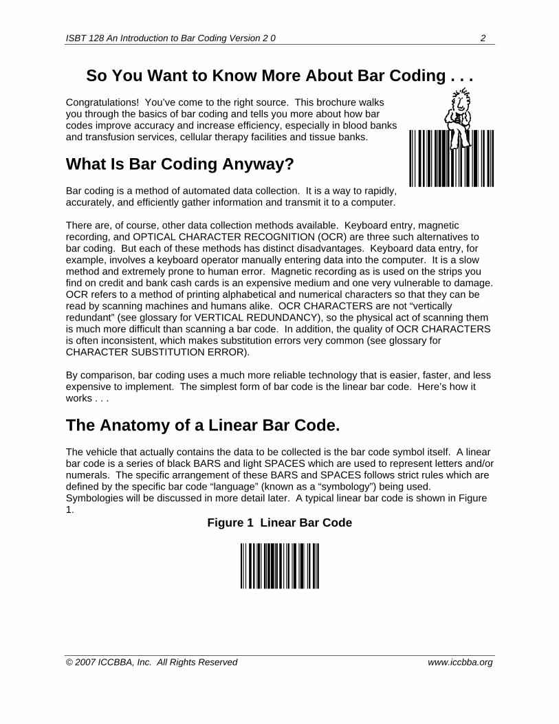
The Anatomy of a Linear Bar Code. The vehicle that actually contains the data to be collected is the bar code symbol itself. A linear bar code is a series of black BARS and light SPACES which are used to represent letters and/or numerals. The specific arrangement of these BARS and SPACES follows strict rules which are defined by the specific bar code “language” (known as a “symbology”) being used. Symbologies will be discussed in more detail later. A typical linear bar code is shown in Figure 1.
Figure 1 Linear Bar Code

ISBT 128 An Introduction to Bar Coding Version 2 0 3
© 2007 ICCBBA, Inc. All Rights Reserved www.iccbba.org
How Does a Bar Code Work? To decode the information in a bar code, a small spot of light is passed over the BARS and SPACES via a scanning device. This bar code scanner (also referred to as a “reader”) can be a hand-held wand, a fixed-beam or moving-beam laser, or a CCD (charge-coupled device). The optical principles of bar coding are similar regardless of the scanning technology used. The bar code symbol will reflect the spot of light back into the scanner in varying amounts—the black BARS absorb light and therefore will reflect very little light back into the scanner, while the white SPACES will reflect much more light. These differences in reflectivity are converted into electrical signals by a light detector within the scanner. The signal is then converted into binary ones and zeroes which are used in various combinations to stand for specific numbers and letters. For example, there is a specific series of binary ones and zeroes within the character set of Code 128 that uniquely represents the letter “A,” which is different from the series of ones and zeroes that translate to the letter “B,” and so on. How fast does this conversion from BARS and SPACES to electrical signals to ones and zeroes happen? Even the “slowest” scanner—one in which the human hand provides the scanning motion—can typically collect data at four to six CHARACTERS per second. Using a CCD or laser scanner is considered by many to be even easier to use: all you do is point and shoot, making sure that the beam traverses all the BARS and SPACES.
Bar Code Languages for the Non-Native Speaker: In order to better understand how bar codes work, let’s look closely at the symbology chosen for ISBT 128: Code 128. No matter what symbology is used, every linear bar code is made up of BARS and SPACES that form “CHARACTERS”. In most simple bar codes these BARS and SPACES are referred to as “ELEMENTS” and are printed in one of two relative widths—narrow and wide. A CHARACTER is a group of these narrow and wide ELEMENTS which together stand for a number or letter. Rather than only two ELEMENT widths, Code 128 contains four. The narrowest width ELEMENT is called a MODULE. Its width is a dimension called “X” and can either be printed as a BAR or not printed and therefore be a SPACE. Each BAR or SPACE is one of four widths: 1X, 2X, 3X, or 4X. A typical Code 128 symbol is diagrammed in Figure 2 to help you understand how this works.
ISBT 128 An Introduction to Bar Coding Version 2 0 4
© 2007 ICCBBA, Inc. All Rights Reserved www.iccbba.org
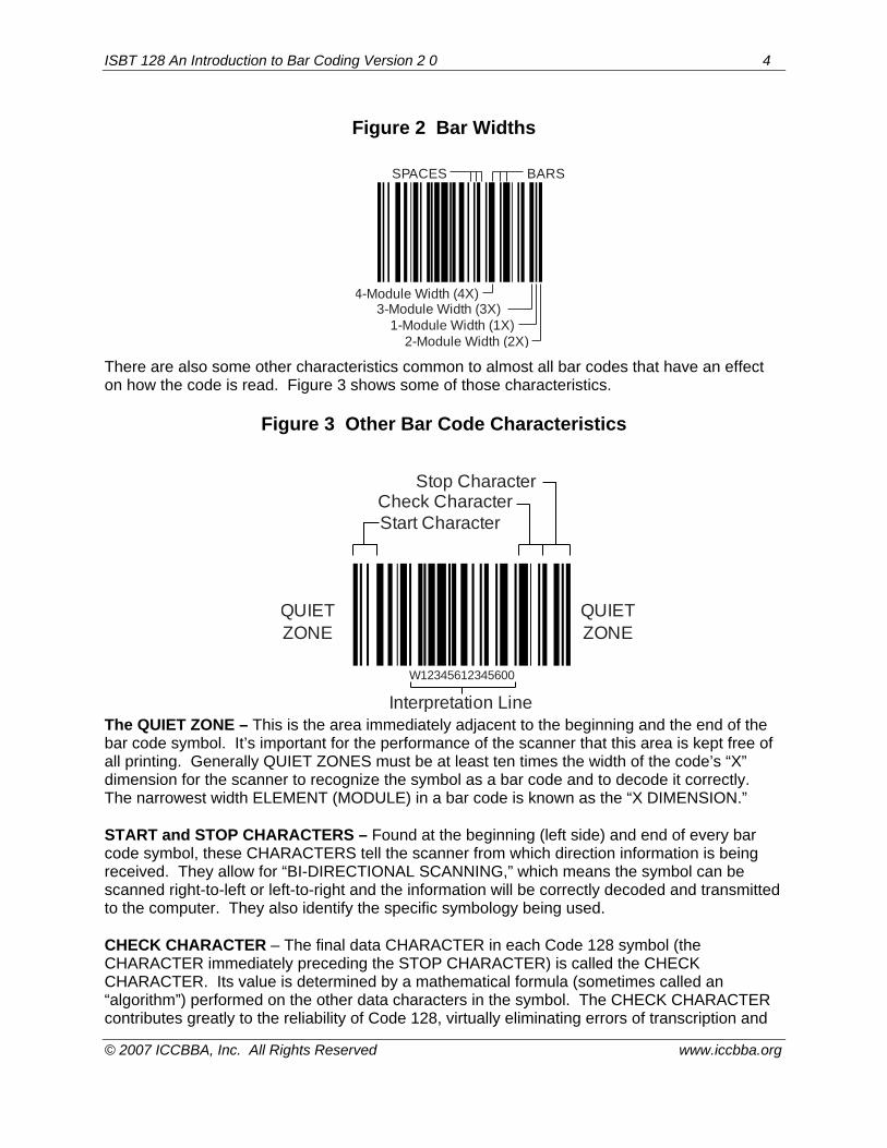
Figure 2 Bar Widths
There are also some other characteristics common to almost all bar codes that have an effect on how the code is read. Figure 3 shows some of those characteristics.
Figure 3 Other Bar Code Characteristics The QUIET ZONE – This is the area immediately adjacent to the beginning and the end of the bar code symbol. It’s important for the performance of the scanner that this area is kept free of all printing. Generally QUIET ZONES must be at least ten times the width of the code’s “X” dimension for the scanner to recognize the symbol as a bar code and to decode it correctly. The narrowest width ELEMENT (MODULE) in a bar code is known as the “X DIMENSION.” START and STOP CHARACTERS – Found at the beginning (left side) and end of every bar code symbol, these CHARACTERS tell the scanner from which direction information is being received. They allow for “BI-DIRECTIONAL SCANNING,” which means the symbol can be scanned right-to-left or left-to-right and the information will be correctly decoded and transmitted to the computer. They also identify the specific symbology being used. CHECK CHARACTER – The final data CHARACTER in each Code 128 symbol (the CHARACTER immediately preceding the STOP CHARACTER) is called the CHECK CHARACTER. Its value is determined by a mathematical formula (sometimes called an “algorithm”) performed on the other data characters in the symbol. The CHECK CHARACTER contributes greatly to the reliability of Code 128, virtually eliminating errors of transcription and
SPACES BARS
4-Module Width (4X)3-Module Width (3X)
1-Module Width (1X)2-Module Width (2X)
Check CharacterStart Character
Stop Character
QUIETZONE
QUIETZONE
W12345612345600
Interpretation Line
ISBT 128 An Introduction to Bar Coding Version 2 0 5
© 2007 ICCBBA, Inc. All Rights Reserved www.iccbba.org
transposition. You can read more about how this CHECK CHARACTER works in the AIM (Association for Automatic Identification and Mobility) specifications for Code 128. See “Additional Resources” at the end of this brochure. Interpretation line – This is the line above or below a bar code where human readable information appears. It may or may not be the same data that is encoded in the bar code, depending on the user’s needs. It is referred to as eye-readable text in ISBT 128 and is found below the bar code. Code 128 has a number of features that make it ideal for use in cellular therapy facilities and blood and tissue banks. In addition to being able to encode the full ASCII control character set, double-density encodation of numeric data is possible, conserving valuable space on cellular therapy, blood and tissue containers. With an appropriately-equipped scanner, it also supports timed concatenation, which allows the user to scan two adjacent symbols in a single pass electronically linking a specific donation number, for example, with the correct ABO label.
How to Tell a Good Bar Code from a Bad One. There are many ingredients that go into the “recipe” for a fast and effective automatic data collection system. Some of them are beyond the scope of this booklet, but two need to be addressed: the match of scanner resolution to symbol DENSITY and the quality of the bar code itself. For best results, the spot of light emitted from the scanner (sometimes called the spot of optical resolution) should be about 70% of the size of the narrowest ELEMENT it will encounter. A 10 mil (0.010”) narrow ELEMENT, for example, should be scanned with a spot size of about 7 mils. Keep in mind that laser and non-contact CCD scanners have varying spot sizes, depending upon the distance between the scanner and the symbol. A contact wand, on the other hand, has a fixed-size spot. The best advice is to try all scanners and label combinations for first-pass READ RATE performance prior to purchase. The quality of the bar code image is absolutely critical to the effectiveness of the automated data collection system. There are several criteria you can use to distinguish high quality bar code labels from poorly made ones. The first thing to look for is dimensional accuracy and consistency. You’ll remember we said that the narrow ELEMENT, or MODULE in the case of Code 128, in a bar code is called its “X DIMENSION.” This dimension determines the “DENSITY” of the bar code, or how much information can be encoded into a given amount of space (usually measured in linear inches). The narrower the X DIMENSION, the higher the DENSITY of the bar code, and therefore the greater the amount of information that can be packed into a given amount of space. The actual width of each ELEMENT in a bar code must be produced within specific tolerances (BAR DIMENSION TOLERANCE) or the bar code will not scan. In high quality bar code labels, this accuracy will be consistent throughout the individual bar code symbol and it will be consistent from label to label.
ISBT 128 An Introduction to Bar Coding Version 2 0 6
© 2007 ICCBBA, Inc. All Rights Reserved www.iccbba.org
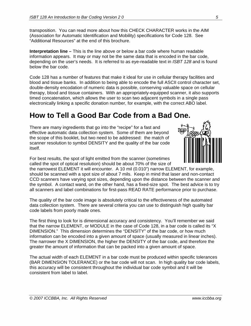
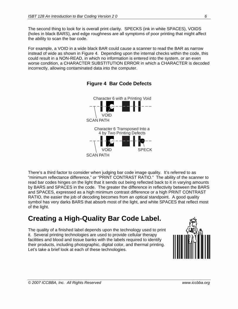
The second thing to look for is overall print clarity. SPECKS (ink in white SPACES), VOIDS (holes in black BARS), and edge roughness are all symptoms of poor printing that might affect the ability to scan the bar code. For example, a VOID in a wide black BAR could cause a scanner to read the BAR as narrow instead of wide as shown in Figure 4. Depending upon the internal checks within the code, this could result in a NON-READ, in which no information is entered into the system, or an even worse condition, a CHARACTER SUBSTITUTION ERROR in which a CHARACTER is decoded incorrectly, allowing contaminated data into the computer.
Figure 4 Bar Code Defects There’s a third factor to consider when judging bar code image quality. It’s referred to as “minimum reflectance difference,” or “PRINT CONTRAST RATIO.” The ability of the scanner to read bar codes hinges on the light that it sends out being reflected back to it in varying amounts by BARS and SPACES in the code. The greater the difference in reflectivity between the BARS and SPACES, expressed as a high minimum contrast difference or a high PRINT CONTRAST RATIO, the easier the job of decoding becomes from an optical standpoint. A good quality symbol has very darks BARS that absorb most of the light, and white SPACES that reflect most of the light.
Creating a High-Quality Bar Code Label. The quality of a finished label depends upon the technology used to print it. Several printing technologies are used to provide cellular therapy facilities and blood and tissue banks with the labels required to identify their products, including photographic, digital color, and thermal printing. Let’s take a brief look at each of these technologies.
VOIDSCAN PATH
Character 6 Transposed Into a4 by Two Printing Defects
Character 6 with a Printing Void
VOID SPECKSCAN PATH

ISBT 128 An Introduction to Bar Coding Version 2 0 7
© 2007 ICCBBA, Inc. All Rights Reserved www.iccbba.org
Photographic The “grandfather” of Donation Identification Numbers (DINs) print technologies, the computer-controlled photographic process, produces original images not printed copies. This technology is used for many of the whole blood number label sets or DINs used in blood banks throughout the world. It bears some resemblance to the process used to expose and develop photographic film. The result is bar code labels that are graphically perfect, abrasion resistant, and archival. How are they made? A moving beam of light “strokes” the bar code image through a lens system onto photosensitive material. This is done in a raster fashion, similar to the way an image is produced on a television screen. After the image is created, the photosensitive material is processed to develop and “fix” the image, much like photographic film from a 35mm camera is developed into prints. Next, PRESSURE-SENSITIVE ADHESIVE is applied to the back of the photographic paper. It is then die-cut into individual label sets. The bar code image is formed within the paper itself, not just laid down on the surface, so the bar code is naturally protected from abrasion and moisture. Bar codes produced via photocomposition can be read by any scanner light source and are produced on archival paper so they will not fade and become unscannable over time. Digital color Many facilities have switched to digital color DIN label sets for several reasons:
• materials are thinner and more compliant than photographic paper and therefore may adhere better to cylindrical tubes and uneven bag surfaces;
• color can be utilized at no additional cost; • overall price of the label set is likely to be less than photographic.
Using a liquid toner, digital imaging utilizes an 812 dpi (dots per inch) print engine. The photo drum is electronically charged as it rotates. The writing head laser beams selectively discharge the photo drum and the latent image is formed. Developer units apply ink to the discharged areas on the photo drum. The discharged areas, which are the image areas, attract the ink particles while the charged areas which are the non-image areas, repel the ink. The image on the photo drum surface is now inked. As in offset printing, digital color transfers the inked image from the photo drum to a blanket, and from the blanket to substrate (label material). However, unlike offset printing, digital color printing creates a different image with each revolution. Digital color printing merges the properties of liquid ink with electronic imaging resulting in electronic printing flexibility (no print plates; all artwork is done via computer) with the high quality of offset printing. The description might make it sound cumbersome, but it’s actually a very consistent and high quality imaging process. It produces virtually flawless bar code symbols, and also offers variable color, a unique feature that allows each DIN label set on the roll to contain a different color than the previous and following sets. The color can be a stripe, a stopper in a test tube icon, or even the eye-readable interpretation line. Some blood banks have elected to use this feature to help their staff distinguish one labeled bag set from another, ensuring that a “red” tube, for example, doesn’t inadvertently get included with a “green” set.
ISBT 128 An Introduction to Bar Coding Version 2 0 8
© 2007 ICCBBA, Inc. All Rights Reserved www.iccbba.org
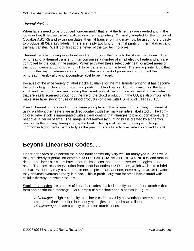
Thermal Printing When labels need to be produced “on-demand,” that is, at the time they are needed and in the location they’ll be used, most facilities use thermal printing. Originally adopted for the printing of Codabar ABO/Rh and expiration dates, thermal transfer printing may now be used more broadly to produce all ISBT 128 labels. There are really two kind of thermal printing: thermal direct and thermal transfer. We’ll look first at the newer of the two technologies. Thermal transfer printing uses label stock and ribbons that have to be of matched types. The print head of a thermal transfer printer comprises a number of small electric heaters which are controlled by the logic in the printer. When activated these selectively heat localized areas of the ribbon cause a dot, or pixel, of ink to be transferred to the label. The same printer logic that controls the heating elements also controls the movement of paper and ribbon past the printhead, thereby allowing a complete label to be imaged. Because of the wide variety of label stocks available for thermal transfer printing, it has become the technology of choice for on-demand printing in blood banks. Correctly matching the label stock and the ribbon, and maintaining the cleanliness of the printhead will result in bar codes that are easily scanned throughout the life of the blood product. [In the US, it’s also important to make sure label stock for use on blood products complies with US FDA 21 CFR 175.105.] Direct Thermal printers work on the same principle but differ in one important way. Instead of using a ribbon, the heaters are in direct contact with thermally sensitive label stock. The light-colored label stock is impregnated with a clear coating that changes to black upon exposure to heat over a period of time. The image is not formed by burning but is created by a chemical reaction in the coating, brought on by the heat This type of thermal printing is no longer common in blood banks particularly as the printing tends to fade over time if exposed to light.
Beyond Linear Bar Codes. . . Linear bar codes have served the blood bank community very well for many years. And while they are clearly superior, for example, to OPTICAL CHARACTER RECOGNITION and manual data entry, linear bar codes have inherent limitations that other, newer technologies do not have. The most obvious evolution from linear bar codes is 2-D codes, which we’ll take a brief look at. While they may never replace the simple linear bar code, there may be areas in which they enhance systems already in place. This is particularly true for small labels found with cellular therapy or tissue products. Stacked bar codes are a series of linear bar codes stacked directly on top of one another that form one continuous message. An example of a stacked code is shown in Figure 5.
Advantages: Higher capacity than linear codes, read by conventional laser scanners, error detection/correction in most symbologies, printed similar to linear Disadvantage: Lower capacity than some matrix codes
ISBT 128 An Introduction to Bar Coding Version 2 0 9
© 2007 ICCBBA, Inc. All Rights Reserved www.iccbba.org
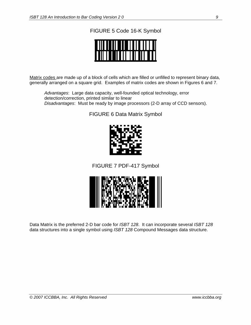
FIGURE 5 Code 16-K Symbol
Matrix codes are made up of a block of cells which are filled or unfilled to represent binary data, generally arranged on a square grid. Examples of matrix codes are shown in Figures 6 and 7.
Advantages: Large data capacity, well-founded optical technology, error detection/correction, printed similar to linear Disadvantages: Must be ready by image processors (2-D array of CCD sensors).
FIGURE 6 Data Matrix Symbol
FIGURE 7 PDF-417 Symbol Data Matrix is the preferred 2-D bar code for ISBT 128. It can incorporate several ISBT 128 data structures into a single symbol using ISBT 128 Compound Messages data structure.
ISBT 128 An Introduction to Bar Coding Version 2 0 10
© 2007 ICCBBA, Inc. All Rights Reserved www.iccbba.org
The Impact of Bar Coding on Productivity or How to Get More Done More Accurately in Less Time than Ever Before. Bar code labels are currently being used in a wide range of medical, business, and industrial applications all over the world. You’ll see them on everything from cereal boxes to engine blocks, from blood containers to printed circuit boards and library books. Their chief benefits can be described in three relatively simple ways: Speed – Using a HAND-HELD SCANNER to read a bar code typically takes no more than two seconds. Assuming that the symbol is an ISBT 128 Donation Identification Number, the speed with which that information can be read and stored is about six CHARACTERS per second, three times faster than a keyboard. With moving-beam laser and CCD scanners, data entry is even faster than that. Indeed, many automated instruments used in the blood testing laboratory require no operator intervention at all. Data entry is accomplished via “hands-off” scanning. Accuracy – Life usually involves trade-offs. “Do you want this done quickly or correctly?” With bar codes, there’s no trade-off between speed and accuracy. Manual data entry typically results in one error for every 100-300 keystrokes. With high quality Code 128 symbol, error rates can be lower than one error in every 30-40 million CHARACTERS scanned. Reliable, easy-to-use technology – You don’t need to be an engineer to perform bar code scanning. Most people can be fully trained in the use of a CCD or laser scanner in minutes. Perhaps the most striking documented case for improving productivity with bar codes comes from a study done by the U. S. Department of Defense (DoD) in the early 1980s. Using clipboards and stopwatches, the DoD recorded the time required to enter data via keyboard, OCR, and bar coding. When the massive study was completed, the hands-down winner was bar code scanning. The U. S. Navy alone estimated it could save $114 million per year over a ten-year period with bar code systems implemented throughout their organization. Perhaps of more interest to cellular therapy facilities, and blood and tissue banks, they discovered their productivity in some areas increased by 400%. The international cellular therapy, blood and tissue banking communities will achieve similar improvements in accuracy and productivity with the broad implementation of ISBT 128. When the medic involved in an international peace-keeping mission scans a unit of blood prior to transfusion and can verify it’s a match, global standardization has paid off richly. As biological products are transported over state lines and national borders, a universally accepted identification system is critical in maintaining not only the safety but also the availability of these products. Developing and validating software written to a single standard is simpler, more efficient, and therefore less costly for everyone. Whether you’re a cellular therapy, blood or tissue bank professional, a healthcare provider, or a consumer who might someday need a biological product, standardizing the packaging of these most important products and automating their identification is a benefit to us all.
ISBT 128 An Introduction to Bar Coding Version 2 0 11
© 2007 ICCBBA, Inc. All Rights Reserved www.iccbba.org
Additional Resources
1. Bar code symbology specifications are available from the Association for Automatic Identification and Mobility at AIM Global, 125 Warrendale-Bayne Road, Warrendale, PA 15086; USA. Telephone: 724/934-4470 Fax: 724/934-4495. http://www.aimglobal.org/
2. European readers may prefer to access a local website for AIM: http://www.aim-d.de/ 3. Wray, BR: Bar code data collection in the blood bank. In: Butch, SH and Simpson, MB
(eds): Information Technology in Transfusion Medicine. Bethesda, MD: AABB, 2002:17-54.

ISBT 128 An Introduction to Bar Coding Version 2 0 12
© 2007 ICCBBA, Inc. All Rights Reserved www.iccbba.org
Glossary Bar – The dark element in a bar code. Can be either wide or narrow (with Code 128, one of four widths). Alternates with white spaces. See SPACE. Bar dimension tolerance –A measure of the permitted width tolerance of an element. Close adherence to this tolerance distinguishes high quality bar code symbols from poor quality codes. High-density bar codes require extremely accurate tolerances. See DENSITY. Bi-directional scanning – The bar code property that allows codes to be scanned either from left to right or from right to left. Made possible by the presence of start and stop characters in the code. See START CHARACTER, STOP CHARACTER. Character – A group of elements in a bar code which together stand for a letter, number or other symbol. See ELEMENT. Character substitution error – Occurs when the scanner mis-reads a bar code symbol and substitutes a wrong character for the one actually encoded. Often caused by poor label quality. One form of mis-read. See MIS-READ. Check character – A character in a bar code symbol which allows the scanner to mathematically determine that it has read the bar code correctly. Density – An expression of the amount of information a bar code can hold in a given amount of space. Usually measured in linear inches. Bar codes are classified as high, medium or low density codes. Element – An individual bar or space in a bar code. Combinations of elements make up characters. See CHARACTER. First-read rate – Expressed as a percent, the number of correct readings that will be obtained by the scanner wand per 100 attempts. Fixed beam scanner – A bar code scanner which uses a fixed beam of light to read bar code symbols. The symbols themselves must be passed through the beam of light. See HAND-HELD SCANNER, MOVING BEAM SCANNER. Hand-held scanner – A portable scanner used by a human operator which can be brought to the bar codes. The scanner wand is moved across the codes and the symbols themselves remain stationary. See FIXED BEAM SCANNER, MOVING BEAM SCANNER. Mis-read – Occurs when the scanner enters incorrect information into the system. Can involve a character substitution error. See CHARACTER SUBSTITUTION ERROR, NON-READ. Module – The narrowest width ELEMENT. Moving beam scanner – A bar code scanner that “searches” for bar code marks by sweeping a moving optical beam over an object. See HAND-HELD SCANNER, FIXED BEAM SCANNER.
ISBT 128 An Introduction to Bar Coding Version 2 0 13
© 2007 ICCBBA, Inc. All Rights Reserved www.iccbba.org
Non-read – A condition in which a scanning attempt has been made that is unsuccessful. No information is entered into the system. See MIS-READ. Optical character recognition (OCR) – An automatic data entry system which uses human-readable, squared off alphanumeric symbols which can be scanned and read by special scanning equipment. Sometimes used in conjunction with bar code symbols. Pressure-sensitive adhesive (PSA) – The most common variety of adhesive used to back a bar code label. Print contrast ratio (PCR) – Expressed as a percent, a calculation of the differences in reflectivity between the bars and spaces in a bar code symbol. Most scanners require a minimum PCR of 60%-70% to work reasonably accurately. Quiet zone – The areas in front of the bar code start character and following the stop character that designate the parameters of the code. Space – The white element in a bar code. Can be either wide or narrow (with Code 128, one of four widths). Alternates with bars to make up a code symbol. See BAR. Specks – Ink spots that appear in the white spaces of a bar code. Caused by poor printing techniques. Can result in mis-reads or non-reads. See MIS-READ, NON-READ. Start character – The character at the beginning of a bar code that tells the scanner from which direction the code is being read. Allows for bi-directional scanning. See BI-DIRECTIONAL SCANNING, STOP CHARACTER. Stop character – The character at the end of a bar code that tells the scanner from which direction the code is being read. Allows for bi-directional scanning. See BI-DIRECTIONAL SCANNING, START CHARACTER. Vertical redundancy – The property of a bar code that allows a scanner beam to pass through a bar code symbol at practically any angle and still read it accurately. The entire height of the bars and spaces in the linear bar code carries the coded information. Voids – White holes in the black bars of a bar code. Caused by poor printing techniques. Can result in mis-reads and non-reads. See MIS-READ, NON-READ. Wide-to-narrow ratio – The ratio between the widths of the wide elements in a bar code to the width of its narrow elements. A characteristic that affects code density. See DENSITY. X dimension – The width of the narrowest element (module) in a bar code. The narrower the X dimension, the higher the bar code density. See DENSITY, WIDE-TO-NARROW RATIO.


