EMPIR 14SIP01 Workshop – Dr. Karl Jousten, PTB, Vacuum Metrology 1 Jan 30 to Feb 1, 2017 ISO TS 20177 Procedures to measure and report outgassing rates Introduction 1. Purpose and scope 2. Structure of content
Transcript
EMPIR 14SIP01 Workshop – Dr. Karl Jousten, PTB, Vacuum Metrology 1 Jan 30 to Feb 1, 2017
ISO TS 20177 Procedures to measure and
report outgassing rates
Introduction
1. Purpose and scope
2. Structure of content
2
ISO TS 20177 (WD)
EMPIR 14SIP01 Workshop – Dr. Karl Jousten, PTB, Vacuum Metrology Jan 30 to Feb 1, 2017
qout ≤ 1·10-5 Pa m³/s (-> discussion later) Total outgassing rate and species outgassing rate For total outgassing rate: concept of nitrogen equivalent (-> discussion later) No direct line of sights required (-> discussion later) Methods described in TS shall be comparable Traceability a must for each method Relatively high uncertainties acceptable (more than 10% o.k.)
Scope/suppositions
3
ISO TS 20177 (WD)
EMPIR 14SIP01 Workshop – Dr. Karl Jousten, PTB, Vacuum Metrology Jan 30 to Feb 1, 2017
Structure of Content
1. Scope2. Normative references3. Terms and definitions4. Symbols and abbreviated terms
EMPIR 14SIP01 Workshop – Dr. Karl Jousten, PTB, Vacuum Metrology Jan 30 to Feb 1, 2017
5. Measurement systems
1. General recommendations for systems, chambers and pumps, gauges)
1. Recommendations for systems2. Chambers and pumps3. Vacuum gauges
2. Systems applying the throughput method
1. Continuous expansion system as flow comparator2. Throughput system with calulated conductance element
(one and two path design) 3. Throughput system with measured effective pumping speed4. Throughput system with modulated conductance
3. Accumulation systems
1. Basic accumulation system2. Accumulation system with gas analysis
5
ISO TS 20177 (WD)
EMPIR 14SIP01 Workshop – Dr. Karl Jousten, PTB, Vacuum Metrology Jan 30 to Feb 1, 2017
6. Measurement procedures
1. Recommended sample preparation 2. Course and time period of measurement3. Particular measurement procedures
1. Procedure with continuous expansion system as flow comparator
2. Procedure with throughput system with calulated conductance element
3. Procedure with throughput system with measured effective pumping speed
4. Procedure with throughput system with modulated conductance
5. Procedure with accumulation systems
6
ISO TS 20177 (WD)
EMPIR 14SIP01 Workshop – Dr. Karl Jousten, PTB, Vacuum Metrology Jan 30 to Feb 1, 2017
6. Measurement uncertainties
• Continuous expansion system as flow comparator• Throughput system with calulated conductance element • Throughput system with measured effective pumping speed• Throughput system with modulated conductance• Basic accumulation system• Accumulation system with gas analysis
Editorial: Numbering requested?
7
ISO TS 20177 (WD)
EMPIR 14SIP01 Workshop – Dr. Karl Jousten, PTB, Vacuum Metrology Jan 30 to Feb 1, 2017
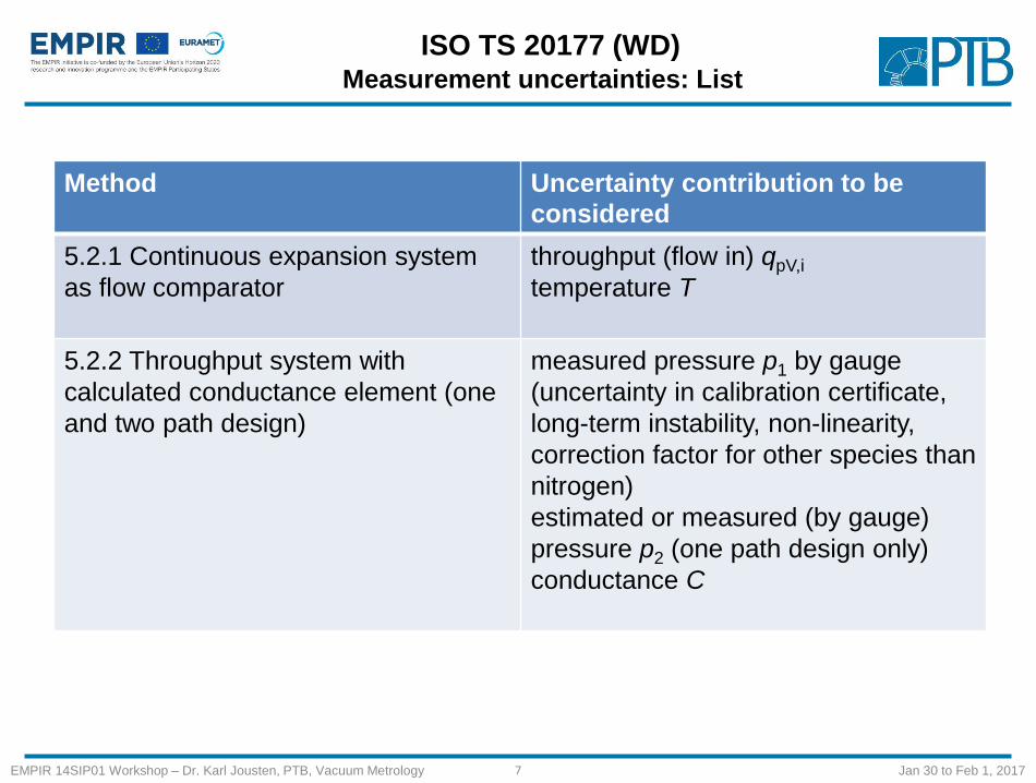
Measurement uncertainties: List
Method Uncertainty contribution to be
considered
5.2.1 Continuous expansion system
as flow comparator
throughput (flow in) qpV,i
temperature T
5.2.2 Throughput system with
calculated conductance element (one
and two path design)
measured pressure p1 by gauge
(uncertainty in calibration certificate,
long-term instability, non-linearity,
correction factor for other species than
nitrogen)
estimated or measured (by gauge)
pressure p2 (one path design only)
conductance C
8
ISO TS 20177 (WD)
EMPIR 14SIP01 Workshop – Dr. Karl Jousten, PTB, Vacuum Metrology Jan 30 to Feb 1, 2017
Measurement uncertainties: List
Method Uncertainty contribution to be
considered
5.2.3 Throughput system with
measured effective pumping speed
flow from standard leakpossible change of CN2 due to unknown change with pressuremeasured pressure p1 by gauge (uncertainty in calibration certificate, long-term instability, non-linearity, correction factor for other species than nitrogen)measured pressure p0 by gaugePosition of gauge or QMSQMS sensitivities
9
ISO TS 20177 (WD)
EMPIR 14SIP01 Workshop – Dr. Karl Jousten, PTB, Vacuum Metrology Jan 30 to Feb 1, 2017
Measurement uncertainties: List
Method Uncertainty contribution to be
considered
5.2.4 Throughput system with
modulated conductance
measurement with vacuum gauge
(uncertainty in calibration certificate,
long-term instability, non-linearity,
correction factor for other species than
nitrogen)
conductances
incomplete equilibrium
10
ISO TS 20177 (WD)
EMPIR 14SIP01 Workshop – Dr. Karl Jousten, PTB, Vacuum Metrology Jan 30 to Feb 1, 2017
Measurement uncertainties: List
Method Uncertainty contribution to be considered
5.3.1 Basic accumulation system accumulation chamber and sample volume V
temperature T
pressure of accumulating gas p
time interval Δt
5.3.2 Accumulation system with
gas analysis system
accumulation chamber and sample volume V,
temperature T
pressure of accumulating gas p
time interval Δt
volume of optional chamber for calibration
gas V
pressure of calibration gas p
nonlinearity of the QMS
11
ISO TS 20177 (WD)
EMPIR 14SIP01 Workshop – Dr. Karl Jousten, PTB, Vacuum Metrology Jan 30 to Feb 1, 2017
5.2.1 Continuous expansion system as flow comparator1 measurement chamber 2 pump chamber 3 by-pass (recommended) 4 sample chamber 5 load-lock 6 sample 7 QMS 8 total pressure gauge 9 pump systems 10 reservoir 11 CDG 12 connection to gas supply
12
ISO TS 20177 (WD)
EMPIR 14SIP01 Workshop – Dr. Karl Jousten, PTB, Vacuum Metrology Jan 30 to Feb 1, 2017
5.2.2 Throughput system
with calculated
conductance (one-path
design)
1 measurement chamber 2
pump chamber 3 vacuum
gauge and QMS (optionally)
4,10 valves 5 by-pass
(optionally) 6 sample 7
sample chamber 8 load lock
9 pump systems
13
ISO TS 20177 (WD)
EMPIR 14SIP01 Workshop – Dr. Karl Jousten, PTB, Vacuum Metrology Jan 30 to Feb 1, 2017
5.2.2 Throughput system
with calculated
conductance (two-path
design)
1 measurement chamber 2
pump chamber 3,4 vacuum
gauge and QMS (optionally)
5 by-pass 6 sample 7 sample
chamber 8 load lock 9 pump
systems 10 second path line
B 11 valve for path A
(upstream), 12 valve for path
B (downstream)
14
ISO TS 20177 (WD)
EMPIR 14SIP01 Workshop – Dr. Karl Jousten, PTB, Vacuum Metrology Jan 30 to Feb 1, 2017
5.2.3 Throughput system with measured
effective pumping speed
1 measurement chamber 2 standard leak 3
vacuum gauge and QMS (optionally) 4 pump
systems 5 sample chamber 6 sample 7 load
lock
15
ISO TS 20177 (WD)
EMPIR 14SIP01 Workshop – Dr. Karl Jousten, PTB, Vacuum Metrology Jan 30 to Feb 1, 2017
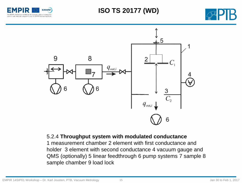
5.2.4 Throughput system with modulated conductance
1 measurement chamber 2 element with first conductance and
holder 3 element with second conductance 4 vacuum gauge and
QMS (optionally) 5 linear feedthrough 6 pump systems 7 sample 8
sample chamber 9 load lock
16
ISO TS 20177 (WD)
EMPIR 14SIP01 Workshop – Dr. Karl Jousten, PTB, Vacuum Metrology Jan 30 to Feb 1, 2017
5.3.1 Basic accumulation system
1 measurement chamber of known volume 2 inert vacuum gauge
3 time measurement 4 pump systems 5 load lock 6 sample
17
ISO TS 20177 (WD)
EMPIR 14SIP01 Workshop – Dr. Karl Jousten, PTB, Vacuum Metrology Jan 30 to Feb 1, 2017
5.3.2 Accumulation system
with gas analysis system
1 measurement chamber of
known volume 2 inert vacuum
gauges 3 time measurement 4
pump systems 5 load lock 6
sample 7 QMS 8 Ionization
vacuum gauge 9 volume for
calibration gas (may also be
connected to chamber 1) 10 to
gas reservoir
18
ISO TS 20177 (WD)
EMPIR 14SIP01 Workshop – Dr. Karl Jousten, PTB, Vacuum Metrology Jan 30 to Feb 1, 2017
System Vapour
outgassing
Outgassing
is time
dependent
Identifies
species
Outgassing
rate > 10-9 Pa
m³ s-1
Outgassing
rate 10-9 Pa
m³ s-1
Accuracy Effort,
Experience
Sample is
chamber
5.2.1 Continuous
expansion system as
flow comparator
+ ++ ++ + - ++ Very high +
5.2.2 Throughput
system with
calculated
conductance element
(one path design)
+ ++ ++ + + + high +
5.2.2 Throughput
system with
calculated
conductance element
(two path design)
+ - ++ + ++ + high +
5.2.3 Throughput
system with
measured effective
pumping speed
+ ++ - + - -- low +
5.2.4 Throughput
system with
modulated
conductance
- - ++ + ++ + high +
5.3.1 Basic
accumulation system
-- - -- + ++ + low ++
5.2.3 Accumulation
system with gas
analysis system
-- - + + ++ + high +
Table 3 — Applicability and characteristic of the different measurement systems. It means: ++ well suited, + suitable, - less suitable , --- not suitable
19
ISO TS 20177 (WD)
EMPIR 14SIP01 Workshop – Dr. Karl Jousten, PTB, Vacuum Metrology Jan 30 to Feb 1, 2017
Method Traceable quantity Unit Traceable device Note
5.2.1 Continuous expansion system as flow comparator
C m³ s-1 = 10³ L s-1
One or several conductance elements
Specific for gas species
pi Pa
Vacuum gauge for medium and rough vacuum, preferentially with gas independent indication
Pressure of gas species i in reservoir, measured by secondary standard
5.2.2 Throughput system with calculated conductance element (one and two path design)
C m³ s-1 = 10³ L s-1 Orifice or short duct Specific for gas
species
p PaVacuum gauge for high and ultrahigh vacuum
Calibrated for nitrogen
pi Pa Quadrupol mass spectrometer
Optional, sensitivity for gas species i , stability check by sensitivity nitrogen
Table 4 — Quantities, by which traceability of outgassing rate (either total or partial) to the SI is established in the different measurement systems
20
ISO TS 20177 (WD)
EMPIR 14SIP01 Workshop – Dr. Karl Jousten, PTB, Vacuum Metrology Jan 30 to Feb 1, 2017
Method Traceable quantity Unit Traceable device Note
5.2.3 Throughput system with measured effective pumping speed
qpV Pa m³ s-1 Nitrogen standard leak To determine Ceff
p PaVacuum gauge for high and ultrahigh vacuum
Calibrated for nitrogen
qpV,i Pa m³ s-1 Standard leak for gas species i
Option, if QMS is used, to determine Ceff,i
5.2.4 Throughput system with modulated conductance
C m³ s-1 = 10³ L s-1
Two orifices or short ducts
Specific for gas species
p PaVacuum gauge for high and ultrahigh vacuum
Calibrated for nitrogen
pi Pa Quadrupol mass spectrometer
Optional, sensitivity for gas species i , stability check by sensitivity nitrogen
21
ISO TS 20177 (WD)
EMPIR 14SIP01 Workshop – Dr. Karl Jousten, PTB, Vacuum Metrology Jan 30 to Feb 1, 2017
Method Traceable quantity Unit Traceable device Note
5.3.1 Basic accumulation system
V m³ Chamber volume
p PaVacuum gauge for high and medium vacuum
Calibrated for nitrogen
t s clock
22
ISO TS 20177 (WD)
EMPIR 14SIP01 Workshop – Dr. Karl Jousten, PTB, Vacuum Metrology Jan 30 to Feb 1, 2017
Method Traceable quantity Unit Traceable device Note
5.2.3 Accumulation system with gas analysis system


![outgassing forgiving [OGF] | low cure [LC] - TIGER · PDF fileSerie 40 Ausgasungsarm [AGA] | Niedertemperatur [NT] Series 40 outgassing forgiving [OGF] | low cure [LC] Pulverbeschichtung](https://static.documents.pub/doc/80x56/5abb55de7f8b9a441d8cb1ff/outgassing-forgiving-ogf-low-cure-lc-tiger-40-ausgasungsarm-aga-niedertemperatur.jpg)


