Published in IET Communications Received on 14th August 2009 Revised on 18th February 2010 doi: 10.1049/iet-com.2009.0521 ISSN 1751-8628 Signal transmission with unequal error protection in relay selection networks H.X. Nguyen 1 H.H. Nguyen 1 T. Le-Ngoc 2 1 Department of Electrical and Computer Engineering, University of Saskatchewan, 57 Campus Drive, Saskatoon, Sask., Canada S7N 5A9 2 Department of Electrical and Computer Engineering, McGill University, 3480 University Street, Montreal, Quebec, Canada H3A 2A7 E-mail: [email protected]Abstract: A relaying technique based on single-relay selection is studied for multiple-relay networks when hierarchical modulation is employed for unequal error protection. A single-relay selection scheme achieves a higher bandwidth efficiency while maintaining the same diversity order as when all the relays are selected in a multiple-relay network. Specifically, a cooperative network with one source, K relays, and one destination is considered in which two different protection information classes are modulated by a hierarchical 2/ 4- amplitude shift keying (ASK) constellation at the source. After selecting a relay to cooperate with the source, based on the instantaneous received signal-to-noise ratio, the selected relay decides to retransmit both classes by using a hierarchical 2/ 4-ASK constellation, or the more protection class by using a 2-ASK constellation, or remains silent. The approximated bit error rate (BER) of each information class is derived. Optimal thresholds are chosen to minimise the BER of one class while the BER of the other class satisfies a requirement. Numerical and simulation results are provided to validate the analysis. The results also show that the optimal thresholds can improve the error performance significantly. 1 Introduction In wireless communications, implementing multiple transmit and/or receive antennas to provide spatial diversity might not be possible owing to the size and cost limitations. Cooperative (or relay) diversity has emerged as a promising technique to overcome such limitations. The basic idea is that the source cooperates with other nodes (or relays) in the network to form a virtual multiple antenna system [1–5]. However, with the decode-and-forward (DF) protocol, cooperative communication does not achieve a full diversity order if the relays always retransmit the decoded messages. This is due to possible retransmission of erroneously decoded bits of the message from the relays. Moreover, transmissions from relays to the destination are usually carried out in mutually orthogonal channels, which reduces bandwidth efficiency. To overcome these disadvantages, selection relaying has been proposed for cooperative systems. The operation is based on the selection of the best relay that yields the maximum instantaneous signal-to-noise ratio (SNR) of the relay–destination link in a set of ‘reliable’ relays. In general, a relay is in the set of reliable relays if the instantaneous SNR of the source–relay link is larger than a predefined threshold. The single-relay selection scheme achieves a higher bandwidth efficiency while maintaining the same diversity order as the conventional cooperative scheme. For convenience, the scheme in which all the relays are selected to transmit to the destination over orthogonal channels shall be referred to as a conventional cooperative scheme [6–8]. Unequal error protection (UEP) is an important consideration in wireless communication systems. In particular, this technique protects data according to the system requirements. In poor channel conditions, the receiver recovers the more important classes (known as basic or coarse data) while the less important classes (known as refinement or enhancement data) are recovered from better channel conditions. In the literature, a large amount of research work related to UEP in point-to-point 1624 IET Commun., 2010, Vol. 4, Iss. 13, pp. 1624–1635 & The Institution of Engineering and Technology 2010 doi: 10.1049/iet-com.2009.0521 www.ietdl.org
Transcript
16
&
www.ietdl.org
Published in IET CommunicationsReceived on 14th August 2009Revised on 18th February 2010doi: 10.1049/iet-com.2009.0521
ISSN 1751-8628
Signal transmission with unequal errorprotection in relay selection networksH.X. Nguyen1 H.H. Nguyen1 T. Le-Ngoc2
1Department of Electrical and Computer Engineering, University of Saskatchewan, 57 Campus Drive, Saskatoon, Sask.,Canada S7N 5A92Department of Electrical and Computer Engineering, McGill University, 3480 University Street, Montreal, Quebec,Canada H3A 2A7E-mail: [email protected]
Abstract: A relaying technique based on single-relay selection is studied for multiple-relay networks whenhierarchical modulation is employed for unequal error protection. A single-relay selection scheme achieves ahigher bandwidth efficiency while maintaining the same diversity order as when all the relays are selected ina multiple-relay network. Specifically, a cooperative network with one source, K relays, and one destination isconsidered in which two different protection information classes are modulated by a hierarchical 2/4-amplitude shift keying (ASK) constellation at the source. After selecting a relay to cooperate with the source,based on the instantaneous received signal-to-noise ratio, the selected relay decides to retransmit bothclasses by using a hierarchical 2/4-ASK constellation, or the more protection class by using a 2-ASKconstellation, or remains silent. The approximated bit error rate (BER) of each information class is derived.Optimal thresholds are chosen to minimise the BER of one class while the BER of the other class satisfies arequirement. Numerical and simulation results are provided to validate the analysis. The results also showthat the optimal thresholds can improve the error performance significantly.
1 IntroductionIn wireless communications, implementing multiple transmitand/or receive antennas to provide spatial diversity might notbe possible owing to the size and cost limitations.Cooperative (or relay) diversity has emerged as a promisingtechnique to overcome such limitations. The basic idea isthat the source cooperates with other nodes (or relays) in thenetwork to form a virtual multiple antenna system [1–5].However, with the decode-and-forward (DF) protocol,cooperative communication does not achieve a full diversityorder if the relays always retransmit the decoded messages.This is due to possible retransmission of erroneouslydecoded bits of the message from the relays. Moreover,transmissions from relays to the destination are usuallycarried out in mutually orthogonal channels, which reducesbandwidth efficiency. To overcome these disadvantages,selection relaying has been proposed for cooperative systems.The operation is based on the selection of the best relay thatyields the maximum instantaneous signal-to-noise ratio
24The Institution of Engineering and Technology 2010
(SNR) of the relay–destination link in a set of ‘reliable’relays. In general, a relay is in the set of reliable relays if theinstantaneous SNR of the source–relay link is larger than apredefined threshold. The single-relay selection schemeachieves a higher bandwidth efficiency while maintaining thesame diversity order as the conventional cooperative scheme.For convenience, the scheme in which all the relays areselected to transmit to the destination over orthogonalchannels shall be referred to as a conventional cooperativescheme [6–8].
Unequal error protection (UEP) is an importantconsideration in wireless communication systems. Inparticular, this technique protects data according to thesystem requirements. In poor channel conditions, thereceiver recovers the more important classes (known as basicor coarse data) while the less important classes (known asrefinement or enhancement data) are recovered from betterchannel conditions. In the literature, a large amount ofresearch work related to UEP in point-to-point
IET Commun., 2010, Vol. 4, Iss. 13, pp. 1624–1635doi: 10.1049/iet-com.2009.0521
IEdo
www.ietdl.org
communications exists [9–17]. However, only a few studieswere concentrated on UEP in cooperative networks. Forexample, in [18], the source broadcasts the signals tomultiple destinations by employing hierarchical modulation.Cooperation maximum ratio combining is applied at eachdestination to decode the signals. However, the system hasa high complexity since each destination is required to knowthe instantaneous bit error rates (BERs) of all previousdestinations. The work in [19] considers a three-nodecooperative network and the relay always retransmits thedecoded message to the destination. The distanceparameters of the constellation are optimised to minimisethe BERs. However, the continuous retransmission of therelay can cause error propagation, which limits the BERperformance of the system. Reference [20] proposes a two-threshold method in a single-relay network usinghierarchical modulation. Based on the instantaneousreceived SNR at the relay, the relay retransmits both classes,or the more protection class, or remains silent in the secondphase. The results in [20] show that the two-thresholdmethod improves the performance significantly comparedwith the conventional one-threshold method.
This work is a further development of [20]. It isconcerned with a multiple-relay network employinghierarchical modulation for UEP of two differentinformation classes at the source. A single-relay selectionscheme is employed to select the ‘best’ relay to cooperatewith the source. In particular, after receiving the signal inthe first phase from the source, all relays form threedifferent subsets with different reliability indicators basedon the instantaneous received SNRs of the source–relaylinks. A single relay is selected from the most reliablesubset that yields the highest SNR of relay–destinationlink. Based on the subset that the selected relay is in, theselected relay might retransmit both classes, the moreimportant class or remains silent in the second phase. Tosimplify our derivations, we assume that a hierarchical 2/4-amplitude shift keying (2/4-ASK) constellation is usedat the source. At the selected relay, depending on theinstantaneous received SNR, a hierarchical 2/4-ASK or 2-ASK constellation is employed. It should be noted thatthe use of hierarchical 2/4-ASK modulation is forsimplicity of presentation. Our framework can beextended to a general hierarchical QAM modulation withmany different classes. The approximated BERformulation for each information class is derived and isshown to be very tight. Based on the tight BERapproximation, the use of the optimal thresholds at therelays is discussed to minimise the BER of oneinformation class while the BER of the other informationclass satisfies a requirement.
The remainder of this paper is organised as follows.Section 2 describes the system model. Section 3 presentsBER computations and discusses the use of optimalthresholds. Numerical and simulation results are presentedin Section 4. Finally, Section 5 concludes the paper.
T Commun., 2010, Vol. 4, Iss. 13, pp. 1624–1635i: 10.1049/iet-com.2009.0521
Notations: E{x} is the expectation of x and CN (0, s2) denotesa circularly symmetric complex Gaussian random variablewith variance s2. |V| denotes the cardinality of the set V.
The Q-function is defined as Q(x) =�1
x(1/
����2p
√)e−t2/2 dt.
2 System modelConsider a wireless network with K + 2 nodes as illustratedin Fig. 1. There are one source node, K relay nodes, andone destination node. Every node has only one antenna. Asource node S sends its message to a destination node Dwith the assistance of K relay nodes, denoted by Rk,k = 1, 2, . . . , K . Assume that all nodes operate in a half-duplex mode, that is, a node cannot transmit and receivesimultaneously and a DF protocol is employed at the relays.The symbols at the source node S are modulated to xs by ahierarchical 2/4-ASK constellation as shown in Fig. 2,where bit i1 is more protected than bit i2. In the firstphase, S transmits signals, K relays and D receive. Thereceived signals at Rk and D can be written, respectively, as
ysrk=
���Es
√hsrk
xs + nsrk(1)
ysd =���Es
√hsdxs + nsd (2)
where Es is the average symbol energy at S, hsrk, hsd are the
channel fading coefficients between S and Rk, S and D,respectively, and nsrk
, nsd are the noise components at Rk
and D, respectively.
In order to avoid error propagation with the DF protocol,two different SNR thresholds shall be employed at each relay.
& The Institution of Engineering and Technology 2010
16
&
www.ietdl.org
They are denoted by gth1 and gth
2 , where gth1 , gth
2 [20].When the instantaneous SNR of the S–Rk link, denoted bygsrk
, is larger than gth2 , Rk likely decodes both bits correctly.
When it is between gth1 and gth
2 , only the more importantbit is likely to be decoded correctly. If it is less than gth
1 , Rk
likely decodes both bits incorrectly. Mathematically, threesubsets with different reliability can be defined asV1 W {k [ Srelay:gsrk
, gth1 }, V2 W {k [ Srelay :gth
1 , gsrk
, gth2 }, V3 W {k [ Srelay:gsrk
. gth2 }, where Srelay =
{1, 2, . . . , K }. Only the best relay in the most reliable non-empty subset is selected to transmit the decoded symbol tothe destination in the second phase. Specifically, if{V3 = O/}, only the relay that yields the highest SNRamong the relay–destination links transmits both classeswith a 2/4-ASK constellation to the destination. If{V3 = O/} and {V2 = O/}, only the ‘best’ relay transmitsthe more important class with a 2-ASK constellation to thedestination. Otherwise, all the relays remain silent in thesecond phase.
If relay Rk is selected to transmit in the second phase, thereceived signal at the destination is given by
yrkd =����Erk
√hrkdxrk
+ nrkd (3)
where xrkand Erk
are the symbol and the average symbolenergy sent by Rk, respectively, hrkd is the channel fadingcoefficient between Rk and D and nrkd is the noisecomponent at D in the second phase.
Depending on what the selected relay transmits in thesecond phase, D combines the signals in the first andsecond phases and decodes. The maximum ratiocombiner (MRC) shall be used at the destination todecode the message.
In this paper, we assume that the channel between anytwo nodes is Rayleigh flat fading, modelled as CN (0, s2
ij),where i, j refers to transmit and receive nodes,respectively. The noise components at the relays and thedestination are modelled as i.i.d. CN (0, N0) randomvariables. The instantaneous received SNR for thetransmission from node i to node j is denoted by gij andcomputed as gij = Ei|hij |2/N0. With Rayleigh fading, theprobability distribution function (PDF) of gij is anexponential random variable. It is given byfij(gij) = (1/s2
ij)e−gij/s
2ij , where s2
ij is the average SNR ofthe i– j link.
To simplify our derivation, we assume that all the source–relay and relay–destination links have the same averagechannel quality, that is, s2
sri= s2
sr and s2rid
= s2rd, where
i = 1, . . . , K . However, the analysis can be straightforwardlyextended to arbitrary average channel qualities.
26The Institution of Engineering and Technology 2010
3 BER computations and optimalthresholdsIn this section, the BER analysis for the proposed relayingscheme is first carried out. Then, simpler BERapproximations for both information classes are obtained.Finally, the optimal thresholds are chosen to minimise theaverage BER of one information class while the averageBER of another information class satisfies a given constraint.
3.1 BER computations
We first classify all different cases that result in differentconditioned BERs at the destination. Then, the averageBERs of two different information bits are obtained asweighted summations of these conditioned BERs. Recallthat, if the instantaneous SNR of the S–Rk link, where Rk
is the selected relay, is larger than the threshold gth2 , the
selected relay transmits both information bits. If it isbetween the thresholds gth
1 and gth2 , the selected relay
transmits the more important bit. Otherwise, the selectedrelay remains silent. Therefore three major groups can beclassified. In the case that gsrk
, gth1 , the destination simply
uses the received signal in the first phase to decode bothbits i1 (more protected bit) and i2 (less protected bit). Inthe case that gth
1 , gsrk, gth
2 , the destination combinestwo received signals in two phases to decode bit i1 and usesthe received signal in the first phase to decode bit i2. Twodifferent cases can be further classified depending on thecorrectness of the decoded bit i1 at the selected relay. Onthe other hand, if gsrk
. gth2 , the destination combines two
received signals in two phases to decode both bits i1 and i2.Since the selected relay may decode either i1 or i2
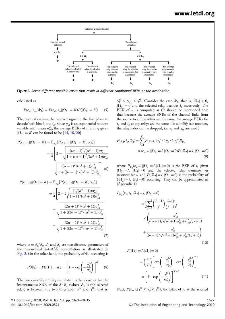
incorrectly, four different cases can be further separated. Allof seven different cases are summarised in Fig. 3 anddenoted by Fj , j = 1, . . . , 7.
Let P(1w, im, Fj) denote the conditional BER of bit im
at node w corresponding to case Fj . With two giventhresholds gth
1 and gth2 , the average BERs for bits i1 and i2
can be written as
BER(gth1 , gth
2 , im) =∑7
j=1
P(1d, im, Fj) (4)
where m = 1, 2. In the following, the approximatedexpressions for seven cases in (4) are determined. It shouldbe noted that for tractability of the analysis, we resort toapproximated BERs. As we will show later, the analyticalBERs obtained from the approximations are very close tothe simulation results.
The first case, F1, occurs when the instantaneous SNRs ofall the S–Rk links, k = 1, . . . , K , are smaller than thethreshold gth
1 . It follows that |V1| = K and|V2| = |V3| = 0. The BERs of im, m = 1, 2, can be
IET Commun., 2010, Vol. 4, Iss. 13, pp. 1624–1635doi: 10.1049/iet-com.2009.0521
www.ietdl.org
Figure 3 Seven different possible cases that result in different conditional BERs at the destination
calculated as
P(1d, im, F1) = P(1d, im||V1| = K )P(|V1| = K ) (5)
The destination uses the received signal in the first phase todecode both bits i1 and i2. Since gsd is an exponential randomvariable with mean s2
sd, the average BERs of i1 and i2 given|V1| = K can be found to be [14, 18, 20]
P(1d, i1||V1| = K ) = Egsd{P(1d, i1||V1| = K , gsd)}
= 1
42 −
������������������������������((a+ 1)2
/(a2 + 1))s2sd
1 + ((a+ 1)2/(a2 + 1))s2
sd
√√√√⎡⎣−
������������������������������((a− 1)2
/(a2 + 1))s2sd
1 + ((a− 1)2/(a2 + 1))s2
sd
√√√√ ⎤⎦ (6)
P(1d, i2||V1| = K ) = Egsd{P(1d, i2||V1| = K , gsd)}
= 1
42 − 2
����������������������(1/(a2 + 1))s2
sd
1 + (1/(a2 + 1))s2sd
√[
+
�������������������������������((2a+ 1)2
/(a2 + 1))s2sd
1 + ((2a+ 1)2/(a2 + 1))s2
sd
√√√√−
�������������������������������((2a− 1)2
/(a2 + 1))s2sd
1 + ((2a− 1)2/(a2 + 1))s2
sd
√√√√ ⎤⎦(7)
where a = d1/d2, d1 and d2 are two distance parameters ofthe hierarchical 2/4-ASK constellation as illustrated inFig. 2. On the other hand, the probability of F1 occurring is
P(F1) = P(|V1| = K ) = 1 − exp − gth1
s2sr
( )[ ]K
(8)
The two cases F2 and F3 are related to the scenario that theinstantaneous SNR of the S–Rk (where Rk is the selectedrelay) is between the two thresholds gth
1 and gth2 , that is,
IET Commun., 2010, Vol. 4, Iss. 13, pp. 1624–1635doi: 10.1049/iet-com.2009.0521
gth1 , gsrk
, gth2 . Consider the case F2, that is, |V2| . 0,
|V3| = 0 and the selected relay decodes i1 incorrectly. TheBER of i1 is computed as (It should be mentioned herethat because the average SNRs of the channel links fromthe source to all the relays are the same, the average BERs fori1 and i2 at any relays are the same. To simplify our notation,the relay index can be dropped, i.e. 1r and gsr are used.)
P(1d, i1,F2)=∑K
l=1
P(1r, i1|gth1 ,gsr ,gth
2 )PF2
× (1d, i1||V2|= l , |V3|=0)P(|V2|= l , |V3|=0)
(9)
where PF2(1d, i1||V2|= l , |V3|=0) is the BER of i1 given
|V2|= l , |V3|=0 and the selected relay transmits anincorrect bit i1 and P(|V2|= l , |V3|=0) is the probability of{|V2|= l , |V3|=0} occurring. They can be approximated as(Appendix 1)
PF2(1d, i1||V2|= l , |V3|=0)
≃ l
2
∑l−1
j=0
l −1
j
( )(−1) j
( j+1)2
× s2rd
((a+1)/�������a2+1
√)s2
sd+s2rd/( j+1)
(
+ s2rd
((a−1)/�������a2+1
√)s2
sd+s2rd/( j+1)
)(10)
P(|V2|= l , |V3|=0)
=K
l
( )exp −gth
1
s2sr
( )−exp −gth
2
s2sr
( )[ ]l
× 1−exp −gth1
s2sr
( )[ ]K−l
(11)
Next, P(1r, i1|gth1 ,gsr ,gth
2 ), the BER of i1 at the selected
1627
& The Institution of Engineering and Technology 2010
1
&
www.ietdl.org
relay given gth1 ,gsr ,gth
2 , needs to be computed to completethe calculation in (9). One can verify that the conditional pdfof gsr, conditioned on gth
1 ,gsr ,gth2 , is
fgsr|gth1
,gsr,gth2
(gsr)=e−gsr/s
2sr
s2sr(e
−gth1/s2
sr − e−gth2/s2
sr )(12)
Using [21, 22, Eq. 3.361.1], the average BER of i1 at theselected relay given gth
1 ,gsr ,gth2 can be found as follows
P(1r, i1|gth1 ,gsr ,gth
2 )
= 1
e−gth1/s2
sr − e−gth2/s2
sr
1
2s2sr
∫gth2
gth1
Q(a+1)
�����2gsr
√�������a2+1
√( )[
+Q(a−1)
�����2gsr
√�������a2+1
√( )]
e−gsr/s2sr dgsr
= 1
2(e−gth1/s2
sr − e−gth2/s2
sr )I1
2(a+1)2
a2+1,s2
sr,gth1
( )[
− I1
2(a+1)2
a2+1,s2
sr,gth2
( )+ I1
2(a−1)2
a2+1,s2
sr,gth1
( )
− I1
2(a−1)2
a2+1,s2
sr,gth2
( )](13)
where
I1(a,s2, x)=∫1
x
Q(���at
√)e−t/s2
s2dt = e−x/s2
Q(���ax
√)
−����������
a
2/s2+a
√Q
������������x
2
s2+a
( )√( )(14)
By substituting (10), (11) and (13) into (9), one can computethe BER of i1 for the case F2.
Similarly, consider the case F3, that is, |V2| . 0, |V3| = 0and the selected relay decodes i1 correctly. The BER of i1
under F3 can be found as
P(1d, i1, F3) =∑K
l=1
[1 − P(1r, i1|gth1 , gsr , gth
2 )]
× PF3(1d, i1||V2| = l , |V3| = 0)
× P(|V2| = l , |V3| = 0) (15)
With sufficiently high SNR (with two positive real functionsf (x) and g(x), we say f (x) = O(g(x)) iflim supx�1 f (x)/g(x) , 1), P(1r, i1|gth
1 , gsr , gth2 ) =
O(1/SNR), PF2(1d, i1||V2| = l , |V3| = 0) is given as in
(10), and PF3(1d, i1||V2| = l , |V3| = 0) , O(1/SNR2)
628The Institution of Engineering and Technology 2010
Under both F2 and F3 cases, the destination uses thereceived signal in the first phase to decode i2. The BERs ofi2 in both cases F2 and F3 are equal and calculated as
P(1d, i2, F2) = P(1d, i2, F3) =∑K
l=1
P(1d, i2||V1| = K )
× P(|V2| = l , |V3| = 0) (16)
The remaining cases, namely F4 –F7, are related to thescenario that the instantaneous SNR of the S–Rk link(where Rk is the selected relay) is larger than the thresholdgth
2 , that is, |V3| . 0. The difference between these cases isthe correctness of the decoded bits i1 and i2 at the selectedrelay. When F4 occurs, the BER of im, m = 1, 2, can befound as
P(1d, im, F4) =∑K
l=1
[1 − P(1r, i1|gsr . gth2 )]
× [1 − P(1r, i2|gsr . gth2 )]
× PF4(1d, im||V3| = l )P(|V3| = l ) (17)
where PF4(1d, im||V3| = l ) is the BER of im given |V3| = l
and P(|V3| = l ) is the probability of |V3| = l occurring.They can be written as (see Appendix 2)
PF4(1d, i1||V3| = l ) =
∑l−1
j=0
l − 1
j
( )(−1) j
2( j + 1)
× I2 s2sr,
s2rd
j + 1,
(a+ 1)2
a2 + 1
( )[
+ I2 s2sr,
s2rd
j + 1,
(a− 1)2
a2 + 1
( )](18)
PF4(1d, i2||V3| = l ) =
∑l−1
j=0
l − 1
j
( )(−1)j
2( j + 1)
× I2 s2sr,
s2rd
j + 1,
1
a2 + 1
( )[
− I2 s2sr,
s2rd
j + 1,
(2a+ 1)2
a2 + 1
( )
+ I2 s2sr,
s2rd
j + 1,
(2a− 1)2
a2 + 1
( )](19)
P(|V3| = l ) =K
l
( )exp − gth
2
s2sr
( )[ ]l
× 1 − exp − gth2
s2sr
( )[ ]K−l
(20)
where I2(·) is as (49) in Appendix 2.
IET Commun., 2010, Vol. 4, Iss. 13, pp. 1624–1635doi: 10.1049/iet-com.2009.0521
Id
www.ietdl.org
Furthermore, P(1r, im|gsr . gth2 ), the average BERs of im
at the selected relay given gsr . gth2 , can be found as [20]
P(1r, i1|gthsr . gth
2 ) = egth2 /s2
sr
2s2sr
∫1
gth2
Q(a+ 1)
�����2gsr
√��������a2 + 1
√( )[
+ Q(a− 1)
�����2gsr
√��������a2 + 1
√( )]
e−gsr/s2sr dgsr
= egth2 /s2
sr
2I1
2(a+ 1)2
a2 + 1, s2
sr, gth2
( )[
+ I1
2(a− 1)2
a2 + 1, s2
sr, gth2
( )](21)
P(1r, i2|gthsr . gth
2 )
= egth2 /s2
sr
4s2sr
∫1
gth2
4Q
�����2gsd
√��������a2 + 1
√( )
− 2Q(2a+ 1)
�����2gsd
√��������a2 + 1
√( )[
+2Q(2a− 1)
�����2gsd
√��������a2 + 1
√( )]
e−gsr/s2sr dgsr
= egth2 /s2
sr
22I1
2
a2 + 1, s2
sr, gth2
( )[
− I1
2(2a+ 1)2
a2 + 1, s2
sr, gth2
( )− I1
2(2a− 1)2
a2 + 1, s2
sr, gth2
( )](22)
By substituting (18)–(22) into (17), the average BERs of i1
and i2 for the case F4 can be computed analytically.Similarly, the BERs of im, m = 1, 2, under the casesF5 –F7, can be found, respectively, as
P(1d, im, F5) =∑K
l=1
P(1r, i1|gsr . gth2 )
× [1− P(1r, i2|gsr . gth2 )]
× PF5(1d, im||V3| = l )P(|V3| = l ) (23)
P(1d, im, F6) =∑K
l=1
[1− P(1r, i1|gsr . gth2 )]
× P(1r, i2|gsr . gth2 )
× PF6(1d, im||V3| = l )P(|V3| = l ) (24)
P(1d, im, F7) =∑K
l=1
P(1r, i1|gsr . gth2 )P(1r, i2|gsr . gth
2 )
× PF7(1d, im||V3| = l )P(|V3| = l ) (25)
ET Commun., 2010, Vol. 4, Iss. 13, pp. 1624–1635oi: 10.1049/iet-com.2009.0521
where (Appendix 2)
PF5(1d, i1||V3| = l )
≃ l
2
∑l−1
j=0
l − 1
j
( )(−1) j
( j + 1)2
× s2rd
s2sd +s2
rd/( j + 1)+ s2
rd
s2sd +s2
rd/( j + 1)
( )(26)
PF7(1d, i1||V3| = l )
≃ l
2
∑l−1
j=0
l − 1
j
( )(−1)j
( j + 1)2
× (a− 1)s2rd
(a+ 1)s2sd + ((a− 1)/(j + 1))s2
rd
[
+ (a+ 1)s2rd
(a+ 1)s2sd + ((a+ 1)/(j + 1))s2
rd
](27)
PF5(1d, i2||V3| = l )
≃ l
2
∑l−1
j=0
l − 1
j
( )(−1) j
( j + 1)2
× (2a+ 1)s2rd
s2sd + ((2a+ 1)/(j + 1))s2
rd
(
− s2rd
(2a+ 1)s2sd + (s2
rd/(j + 1))
)(28)
PF6(1d, i2||V3| = l )
≃ l
2
∑l−1
j=0
l − 1
j
( )(−1) j
j + 1
2s2rd
s2sd + ( j + 1)s2
rd
(29)
PF7(1d, i2||V3| = l )
≃ l
2
∑l−1
j=0
l − 1
j
( )(−1) j
( j + 1)2
× (2a− 1)s2rd
s2sd + ((2a− 1)/(j + 1))s2
rd
(
+ s2rd
(2a− 1)s2sd + (s2
rd/( j + 1))
)(30)
With a similar argument for the case |V3| = 0, one can verifythat P(1d, i1, F6) ≪ P(1d, i1, F5). Therefore we can alsoapproximate P(1d, i1, F6) ≃ 0.
By substituting all the related expressions into the finalformulas of average BERs of two classes in (4), the closed-form expressions result and can be evaluated analytically.Comparison to simulation results in Section 4 shows thatthe BER approximations are very accurate. Based on the
1629
& The Institution of Engineering and Technology 2010
1
&
www.ietdl.org
obtained average BERs, the optimal thresholds can be chosento minimise the average BER of one class while the averageBER of another class satisfies a given constraint. This isfurther discussed next.
3.2 Optimal SNR thresholds
Given the average BERs of two different bits i1 and i2
expressed in (4), one can choose the thresholds to minimisethe BER of the more protected bit i1 when the BER of theless protected bit i2 satisfies a constraint. It should bementioned here that one can also minimise the BER of theless protected bit i2 when the BER of the more protectedbit i1 satisfies a constraint. The optimisation problem canbe set up as follows
(gth1 , gth
2 ) = arg min(gth
1,gth
2)BER(gth
1 , gth2 , i1)
subject toBER(gth
1 , gth2 , i2) ≤ BER2
0 ≤ gth1 ≤ gth
2
{(31)
where BER2 is the BER constraint of the less protected bit.
The above problem can be solved by some optimisationtechniques such as the augmented Lagrange method [23]since the average BER formulas of two bits i1 and i2
have been set up. Here, the optimisation problem in(31) is solved by relying on the MATLAB OptimisationToolbox.
4 Simulation resultsThis section presents analytical and simulation results toconfirm the analysis of the average BERs of two differentinformation classes presented in Section 3.1. In allsimulations, transmission powers are set to be the same forthe source and the relays. The noise components at thesource and the relays are modelled as i.i.d. CN (0, 1)random variables. The average SNR of a link i– j isrepresented by s2
ij = lijEi/N0, where lij is a scaling factorto reflect different distances among nodes. We also use lth
1
and lth2 to represent gth
1 = lth1 Es/N0 and gth
2 = lth2 Es/N0.
Fig. 4 shows the BERs of i1 and i2 at the destination fordifferent values of thresholds lth
1 and lth2 at various channel
conditions and number of relays. Here, a = d1/d2 = 1/0.3and the network is configured with two or three relays. Thefigure shows that the BER approximations are veryaccurate. Therefore the approximations are a useful tool incalculating the BERs for two classes of information bits aswell as to find the optimal relaying thresholds.
Then, Fig. 5 shows the BERs of i1 and i2 for one-threshold and two-threshold methods with similar channelconditions of lsr = lrd = 5lsd = 1. Here, a = 1/0.4 andK = 2. The thresholds for both methods are optimised and
630The Institution of Engineering and Technology 2010
presented in Table 1. Observe from the figure, the BER ofi1 for the two-threshold method improves compared withthat for the one-threshold method, while the BERs of i2
for both methods are identical. With another set ofthreshold values selected randomly, namely {lth
1 = 0.05,lth
2 = 0.4}, the BERs of both protected bits aresignificantly worse compared with that of the two-threshold method.
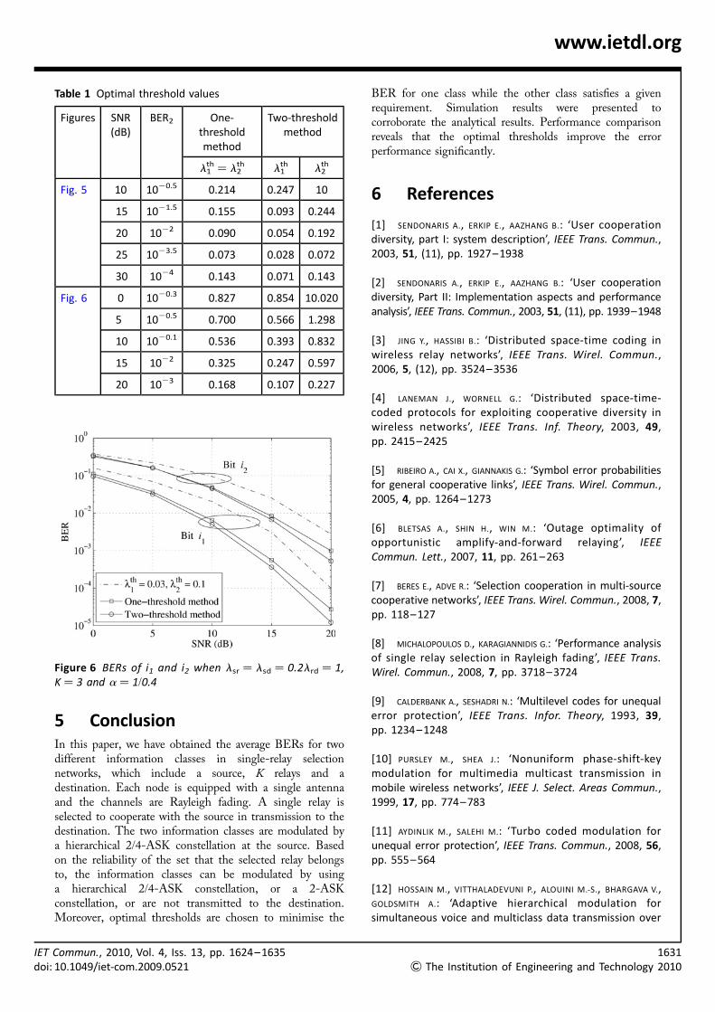
Finally, Fig. 6 shows the improvement of the moreprotected bit when we set BER2 in (31) as in Table 1. Thenetwork is with three relays and a = 1/0.4. The scalingfactors of Rayleigh fading channels are set to belsr = lsd = 0.2lrd = 1. With the two optimal thresholds,the BER of the more protected bit is significantly improvedcompared with that of the arbitrary-threshold and one-threshold methods.
Figure 4 BERs of i1 and i2 when lsr ¼ 0.5lrd ¼ 2lsd ¼ 1
Exact analytical values are shown in lines and simulation resultsare shown as marker symbols
Figure 5 BERs of i1 and i2 when lsr ¼ lrd ¼ 5lsd ¼ 1,K ¼ 2 and a ¼ 1/0.4
IET Commun., 2010, Vol. 4, Iss. 13, pp. 1624–1635doi: 10.1049/iet-com.2009.0521
www.ietdl.org
5 ConclusionIn this paper, we have obtained the average BERs for twodifferent information classes in single-relay selectionnetworks, which include a source, K relays and adestination. Each node is equipped with a single antennaand the channels are Rayleigh fading. A single relay isselected to cooperate with the source in transmission to thedestination. The two information classes are modulated bya hierarchical 2/4-ASK constellation at the source. Basedon the reliability of the set that the selected relay belongsto, the information classes can be modulated by usinga hierarchical 2/4-ASK constellation, or a 2-ASKconstellation, or are not transmitted to the destination.Moreover, optimal thresholds are chosen to minimise the
Table 1 Optimal threshold values
Figures SNR(dB)
BER2 One-thresholdmethod
Two-thresholdmethod
l1th ¼ l2
th l1th l2
th
Fig. 5 10 1020.5 0.214 0.247 10
15 1021.5 0.155 0.093 0.244
20 1022 0.090 0.054 0.192
25 1023.5 0.073 0.028 0.072
30 1024 0.143 0.071 0.143
Fig. 6 0 1020.3 0.827 0.854 10.020
5 1020.5 0.700 0.566 1.298
10 1020.1 0.536 0.393 0.832
15 1022 0.325 0.247 0.597
20 1023 0.168 0.107 0.227
Figure 6 BERs of i1 and i2 when lsr ¼ lsd ¼ 0.2lrd ¼ 1,K ¼ 3 and a ¼ 1/0.4
IET Commun., 2010, Vol. 4, Iss. 13, pp. 1624–1635doi: 10.1049/iet-com.2009.0521
BER for one class while the other class satisfies a givenrequirement. Simulation results were presented tocorroborate the analytical results. Performance comparisonreveals that the optimal thresholds improve the errorperformance significantly.
6 References
[1] SENDONARIS A., ERKIP E., AAZHANG B.: ‘User cooperationdiversity, part I: system description’, IEEE Trans. Commun.,2003, 51, (11), pp. 1927–1938
[2] SENDONARIS A., ERKIP E., AAZHANG B.: ‘User cooperationdiversity, Part II: Implementation aspects and performanceanalysis’, IEEE Trans. Commun., 2003, 51, (11), pp. 1939–1948
[5] RIBEIRO A., CAI X., GIANNAKIS G.: ‘Symbol error probabilitiesfor general cooperative links’, IEEE Trans. Wirel. Commun.,2005, 4, pp. 1264–1273
[6] BLETSAS A., SHIN H., WIN M.: ‘Outage optimality ofopportunistic amplify-and-forward relaying’, IEEECommun. Lett., 2007, 11, pp. 261–263
[7] BERES E., ADVE R.: ‘Selection cooperation in multi-sourcecooperative networks’, IEEE Trans. Wirel. Commun., 2008, 7,pp. 118–127
[8] MICHALOPOULOS D., KARAGIANNIDIS G.: ‘Performance analysisof single relay selection in Rayleigh fading’, IEEE Trans.Wirel. Commun., 2008, 7, pp. 3718–3724
[9] CALDERBANK A., SESHADRI N.: ‘Multilevel codes for unequalerror protection’, IEEE Trans. Infor. Theory, 1993, 39,pp. 1234–1248
[10] PURSLEY M., SHEA J.: ‘Nonuniform phase-shift-keymodulation for multimedia multicast transmission inmobile wireless networks’, IEEE J. Select. Areas Commun.,1999, 17, pp. 774–783
[12] HOSSAIN M., VITTHALADEVUNI P., ALOUINI M.-S., BHARGAVA V.,GOLDSMITH A.: ‘Adaptive hierarchical modulation forsimultaneous voice and multiclass data transmission over
1631
& The Institution of Engineering and Technology 2010
[13] VITTHALADEVUNI P., ALOUINI M.-S.: ‘Exact BER computation ofgeneralized hierarchical PSK constellations’, IEEE Trans.Commun., 2003, 51, pp. 2030–2037
[14] VITTHALADEVUNI P., ALOUINI M.-S.: ‘A recursive algorithm forthe exact BER computation of generalized hierarchical QAMconstellations’, IEEE Trans. Infor. Theory, 2003, 49,pp. 297–307
[15] PEREIRA Z., PELLENZ M., SOUZA R., SIQUEIRA M.A.: ‘Unequalerror protection for LZSS compressed data using Reed-Solomon codes’, IET Commun., 2007, 1, (4), pp. 612–617
[16] KIM J., POTTIE G.: ‘Unequal error protection TCM codes’,IEE Proc. Commun., 2001, 148, (5), pp. 265–272
[17] CHIU M., CHAO C.: ‘Low-decoding-complexity TDM codedmodulation with unequal error protection’, IEE Proc.Commun., 1997, 144, (6), pp. 372–379
[18] WANG T., CANO A., GIANNAKIS G., RAMOS J.: ‘Multi-tiercooperative broadcasting with hierarchical modulations’,IEEE Trans. Wirel. Commun., 2007, 6, pp. 3047–3057
[19] CHANG M.-K., LEE S.-Y.: ‘Performance analysis ofcooperative communication system with hierarchicalmodulation over Rayleigh fading channel’, IEEE Trans.Wirel. Commun., 2009, 8, pp. 2848–2852
[20] NGUYEN H.X., NGUYEN H.H., LE-NGOC T.: ‘Signal transmissionwith unequal error protection in wireless relay networks’,IEEE Trans. Veh. Technol., To be published
[21] HERHOLD P., ZIMMERMANN E., FETTWEIS G.: ‘A simplecooperative extension to wireless relaying. Int. ZurichSeminar on Communications, 2004, pp. 36–39
[22] GRADSHTEYN I.S., RYZHIK I.M., JEFFREY A., ZWILLINGER D.: ‘Table ofintegrals, series, and products’ (Academic Press, 2000)
[24] ONAT F., ADINOYI A., FAN Y., YANIKOMEROGLU H., THOMPSON J.,MARSLAND I.: ‘Threshold selection for SNR-based selectivedigital relaying in cooperative wireless networks’, IEEETrans. Wirel. Commun., 2008, 7, pp. 4226–4237
7 Appendix 1: BER Calculationswhen k [ V2
7.1 Case F2
In this case, the selected relay Rk decodes i1 incorrectly. Thereceived signals at the destination in the first and second
32The Institution of Engineering and Technology 2010
phases are written, respectively, as (Again, we drop theindex of the selected relay for notational simplicity.)
ysd =���Es
√hsd(as1 + s2) + nsd (32)
yrd =���Er
√hrds1 + nrd (33)
where sm is the symbol corresponding to bit im at the source,
m = 1, 2, and s1 is the symbol corresponding to bit i1 at the
selected relay. One has s1, s2 = +d2 = +1/��������a2 + 1
√,
s1 = −(1/d2)s1.
The sufficient statistic after combining two received signalsusing MRC is
yd = a|hsd|2���Es
√−
��������a2 + 1
√|hrd|2
���Er
√( )s1
+ |hsd|2���Es
√s2 + h∗sdnsd + h∗rdnrd (34)
The average BER of the first bit i1 in this case can becomputed as
PF2(1d, i1||V2| = l , |V3| = 0)
= 1
4{PF2
(1d, i1||V2| = l , |V3| = 0, 00 sent)
+ PF2(1d, i1||V2| = l , |V3| = 0, 01 sent)
+ PF2(1d, i1||V2| = l , |V3| = 0, 10 sent)
+ PF2(1d, i1||V2| = l , |V3| = 0, 11 sent)}
= Egsd,grd
1
2Q
((a− 1)/��������a2 + 1
√)gsd − grd���������������
(gsd + grd)/2√( ){
+ 1
2Q
((a+ 1)/��������a2 + 1
√)gsd − grd���������������
(gsd + grd)/2√( )}
(35)
One can verify that the pdf of grd given {|V2| = l , |V3| = 0}is
fgrd||V2|=l ,|V3|=0(grd)
= l
s2rd
∑l−1
j=0
l − 1
j
( )(−1) j exp −( j + 1)
grd
s2rd
( )(36)
Normally, the Rk –D link has a stronger impact on thedecision at the destination than the S–D link. Thereforewe can approximate each component in (35) under thecondition of {mgsd − ngrd , 0} [24], where m . 0, n . 0are two parameters in Q((mgsd − ngrd)/
���������������(gsd + grd)/2
√),
IET Commun., 2010, Vol. 4, Iss. 13, pp. 1624–1635doi: 10.1049/iet-com.2009.0521
Id
www.ietdl.org
that is
∫1
0
∫1
0
Qmgsd − ngrd���������������(gsd + grd)/2
√( )1
s2sds
2rd
e−gsd/s2sd e−grd/s
2rd dgsd dgrd
≃ ns2rd
ms2sd + ns2
rd
(37)
Since gsd and grd are independent, (35) can be approximatedas
PF2(1d, i1||V2| = l , |V3| = 0)
≃ l
2
∑l−1
j=0
l − 1
j
( )(−1) j
( j + 1)2
× s2rd
((a+ 1)/��������a2 + 1
√))s2
sd +s2rd/( j + 1)
(
+ s2rd
((a− 1)/��������a2 + 1
√))s2
sd +s2rd/( j + 1)
)(38)
7.2 Case F3
In this case, the selected relay Rk decodes i1 correctly.The received signals at the destination in two phases aresimilar to (32) and (33). However, s1 = (1/d2)s1. Thedestination combines two received signals using MRC andproduces the following sufficient statistic
yd =���Es
√|hsd|2(as1 + s2) +
���Er
√|hrd|2 s1
+ h∗sdnsd + h∗rdnrd
= a|hsd|2���Es
√+
��������a2 + 1
√|hrd|2
���Er
√( )s1
+ |hsd|2���Es
√s2 + h∗sdnsd + h∗rdnrd (39)
Similar to the case F2, the BER of i1 is as follows
PF3(1d, i1||V2| = l , |V3| = 0)
= 1
4{PF3
(1d, i1||V2| = l , |V3| = 0, 00 sent)
+ PF3(1d, i1||V2| = l , |V3| = 0, 01 sent)
+ PF3(1d, i1||V2| = l , |V3| = 0, 10 sent)
+ PF3(1d, i1||V2| = l , |V3| = 0, 11 sent)}
= Egsd,grd
1
2Q
((a+ 1)/��������a2 + 1
√)gsd + grd���������������
(gsd + grd)/2√( ){
+ 1
2Q
((a− 1)/��������a2 + 1
√)gsd + grd���������������
(gsd + grd)/2√( )}
(40)
ET Commun., 2010, Vol. 4, Iss. 13, pp. 1624–1635oi: 10.1049/iet-com.2009.0521
8 Appendix 2: BER calculationswhen k [ V3
8.1 Case F4
In this case, the received signals at the destination in twophases are
ysd =���Es
√hsd(as1 + s2) + nsd (41)
yrd =���Er
√hrd(as1 + s2) + nrd (42)
where s1, s2 = +d2 = +1/��������a2 + 1
√, s1 = s1 and s2 = s2.
Using MRC to combine the two signals gives
yd =���Es
√|hsd|2(as1 + s2) +
���Er
√|hrd|2
(as1 + s2) + h∗sdnsd + h∗rdnrd
= a���Es
√|hsd|2 +
���Er
√|hrd|2
( )s1
+���Es
√|hsd|2 +
���Er
√|hrd|2
( )s2 + h∗sdnsd + h∗rdnrd (43)
The probabilities of error of i1 and i2 are given, respectively,as
PF4(1d, i1||V3| = l ) = Egsd,grd
1
2Q
(a+ 1)�������������2(gsd + grd)
√��������a2 + 1
√( ){
+ 1
2Q
(a− 1)�������������2(gsd + grd)
√��������a2 + 1
√( )}
(44)
PF4(1d, i2||V3| = l ) = Egsd,grd
Q
�������������2(gsd + grd)
√ ��������a2 + 1
√( ){
− 1
2Q
(2a+ 1)�������������2(gsd + grd)
√��������a2 + 1
√( )
+ 1
2Q
(2a− 1)�������������2(gsd + grd)
√��������a2 + 1
√( )}
(45)
The pdf of grd given |V3| = l can be calculated as
fgrd||V3|=l (grd) = l
s2rd
∑l−1
j=0
l − 1
j
( )(−1) j exp −( j + 1)
grd
s2rd
( )(46)
1633
& The Institution of Engineering and Technology 2010
16
&
www.ietdl.org
Therefore one can easily verify that
PF4(1d, i1||V3| = l ) = Egsd,grd
1
2Q
(a+ 1)�������������2(gsd + grd)
√��������a2 + 1
√( ){
+ 1
2Q
(a− 1)�������������2(gsd + grd)
√��������a2 + 1
√( )}
= 1
2
∑l−1
j=0
l − 1
j
( )(−1) j
j + 1
× I2 s2sr,
s2rd
j + 1,
(a+ 1)2
a2 + 1
( )[
+ I2 s2sr,
s2rd
j + 1,
(a− 1)2
a2 + 1
( )](47)
PF4(1d, i2||V3| = l ) = Egsd,grd
Q
�������������2(gsd + grd)
√ ��������a2 + 1
√( ){
− 1
2Q
(2a+ 1)�������������2(gsd + grd)
√��������a2 + 1
√( )
+ 1
2Q
(2a− 1)�������������2(gsd + grd)
√��������a2 + 1
√( )}
= 1
2
∑l−1
j=0
l − 1
j
( )(−1)j
j + 1
× I2 s2sr,
s2rd
j + 1,
1
a2 + 1
( )[
− I2 s2sr,
s2rd
j + 1,
(2a+ 1)2
a2 + 1
( )
+ I2 s2sr,
s2rd
j + 1,
(2a− 1)2
a2 + 1
( )](48)
where I2(.) is computed as (49)
8.2 Cases F5 to F7
Similar to the case F4, the combination of two receivedsignals by using MRC is
yd =���Es
√|hsd|2(as1 + s2) +
���Er
√|hrd|2
× (as1 + s2) + h∗sdnsd + h∗rdnrd
34The Institution of Engineering and Technology 2010
= a���Es
√|hsd|2s1 +
���Er
√|hrd|2 s1
( )+
���Es
√|hsd|2s2 +
���Er
√|hrd|2 s2
( )+ h∗sdnsd + h∗rdnrd
where s1, s2 = +d2 = +1/��������a2 + 1
√, s1 = +s1 and
s2 = +s2.
With the case F5, the first bit is decoded incorrectly at theselected relay; however, the second bit is decoded correctly,that is, s1 = −s1 and s2 = s2. Therefore (50) becomes
yd = a���Es
√|hsd|2 −
���Er
√|hrd|2
( )s1
+���Es
√|hsd|2 +
���Er
√|hrd|2
( )s2 + h∗sdnsd + h∗rdnrd (51)
The average BERs of i1 and i2 can be calculated as
PF5(1d, i1||V3|= l )
=1
4{PF5
(1d, i1||V3|= l ,00sent)+PF5(1d, i1||V3|= l ,01sent)
+PF5(1d, i1||V3|= l ,10sent)
+PF5(1d, i1||V3|= l ,11sent)}
=Egsd,grd
×{
1
2Q
((a+1)/�������a2+1
√)gsd−((a+1)/
�������a2+1
√)grd��������������
(gsd+grd)/2√( )
+1
2Q ((a−1)/
�������a2+1
√)gsd
(−((a−1)/
�������a2+1
√)grd��������������
(gsd+grd)/2√ )}
(52)
PF5(1d, i2||V3| = l )
= Egsd,grd
× 1
2Q
(1/��������a2 + 1
√)gsd − ((2a+ 1)/
��������a2 + 1
√)grd���������������
(gsd + grd)/2√( ){
− 1
2Q
((2a+ 1)/��������a2 + 1
√)gsd − (1/
��������a2 + 1
√)grd���������������
(gsd + grd)/2√( )
+ 1
2Q
(1/��������a2 + 1
√)gsd + ((2a− 1)/
��������a2 + 1
√)grd���������������
(gsd + grd)/2√( )
I2(s2sr, s
2rd, b) =
1
21 −
����������bs2
rd
1 + bs2rd
√( )2
1 + 1
2
����������bs2
rd
1 + bs2rd
√( ), if s2
rd = s2sd
1
21 −
s2sd
������������������bs2
sd/(1 + bs2sd)
√− s2
rd
������������������bs2
rd/(1 + bs2rd)
√s2
sd − s2rd
⎛⎝ ⎞⎠, if s2rd = s2
sd
⎧⎪⎪⎪⎪⎪⎪⎨⎪⎪⎪⎪⎪⎪⎩(49)
IET Commun., 2010, Vol. 4, Iss. 13, pp. 1624–1635doi: 10.1049/iet-com.2009.0521
IEdo
www.ietdl.org
+ 1
2Q
((2a− 1)/��������a2 + 1
√)gsd + (1/
��������a2 + 1
√)grd���������������
(gsd + grd)/2√( )}
With the pdf of grd given in (46), one can approximate theaverage BERs of i1 and i2 based on (37) as follows
PF5(1d, i1||V3| = l )
= Egsd,grd
× 1
2Q
((a+ 1)/�������a2 + 1
√)gsd − ((a+ 1)/
�������a2 + 1
√)grd��������������
(gsd +grd)/2√( ){
+ 1
2Q
((a− 1)/�������a2 + 1
√)gsd − ((a− 1)/
�������a2 + 1
√)grd��������������
(gsd +grd)/2√( )}
≃ l
2
∑l−1
j=0
l − 1
j
( )(−1) j
( j + 1)2
× s2rd
s2sd +s2
rd/(j + 1)+ s2
rd
s2sd +s2
rd/(j + 1)
( )(54)
PF5(1d, i2||V3|= l )
=Egsd,grdQ
(1/�������a2+1
√)gsd− (1/
�������a2+1
√)grd��������������
(gsd+grd)/2√( ){
+1
2Q
((2a+1)/�������a2+1
√)gsd+ ((2a−1)/
�������a2+1
√)grd��������������
(gsd+grd)/2√( )
+1
2Q
((2a−1)/�������a2+1
√)gsd+ ((2a+1)/
�������a2+1
√)grd��������������
(gsd+grd)/2√( )}
≃ l
2
∑l−1
j=0
l −1
j
( )(−1) j
j+1
2s2rd
s2sd+ ( j+1)s2
rd
(55)
Similarly, one can verify that
PF7(1d, i1||V3| = l )
=Egsd,grd
× 1
2Q
((a+1)/�������a2 +1
√)gsd − ((a−1)/
�������a2 +1
√)grd��������������
(gsd +grd)/2√( ){
+1
2Q
((a−1)/�������a2 +1
√)gsd − ((a+1)/
�������a2 +1
√)grd��������������
(gsd +grd)/2√( )}
≃ l
2
∑l−1
j=0
l −1
j
( )(−1) j
( j +1)2
(a−1)s2rd
(a+1)s2sd + ((a−1)/(j +1))s2
rd
(
+ (a+1)s2rd
(a+1)s2sd + ((a+1)/(j +1))s2
rd
)(56)
T Commun., 2010, Vol. 4, Iss. 13, pp. 1624–1635i: 10.1049/iet-com.2009.0521
PF6(1d, i2||V3| = l )
= Egsd,grd
× 1
2Q
(1/��������a2 + 1
√)gsd − ((2a+ 1)/
��������a2 + 1
√)grd���������������
(gsd + grd)/2√( ){
− 1
2Q
((2a+ 1)/��������a2 + 1
√)gsd − (1/
��������a2 + 1
√)grd���������������
(gsd + grd)/2√( )
+ 1
2Q
(1/��������a2 + 1
√)gsd + ((2a− 1)/
��������a2 + 1
√)grd���������������
(gsd + grd)/2√( )
+ 1
2Q
((2a− 1)/��������a2 + 1
√)gsd + (1/
��������a2 + 1
√)grd���������������
(gsd + grd)/2√( )}
≃ l
2
∑l−1
j=0
l − 1
j
( )(−1)j
( j + 1)2
(2a+ 1)s2rd
s2sd + (2a+ 1/( j + 1))s2
rd
(
− s2rd
(2a+ 1)s2sd + s2
rd/( j + 1)
)(57)
PF7(1d, i2||V3| = l )
= Egsd,grd
× 1
2Q
(1/��������a2 + 1
√)gsd − ((2a− 1)/
��������a2 + 1
√)grd���������������
(gsd + grd)/2√( ){
− 1
2Q
((2a+ 1)/��������a2 + 1
√)gsd + (1/
��������a2 + 1
√)grd���������������
(gsd + grd)/2√( )
+ 1
2Q
(1/��������a2 + 1
√)gsd + ((2a+ 1)/
��������a2 + 1
√)grd���������������
(gsd + grd)/2√( )
+ 1
2Q
((2a− 1)/��������a2 + 1
√)gsd − (1/
��������a2 + 1
√)grd���������������
(gsd + grd)/2√( )}
≃ l
2
∑l−1
j=0
l − 1
j
( )( − 1) j
(j + 1)2
(2a− 1)s2rd
s2sd + ((2a− 1)/( j + 1))s2
rd
(
+ s2rd
(2a− 1)s2sd + s2
rd/( j + 1)
)(58)
1635
& The Institution of Engineering and Technology 2010


![ISSN 1751-8628 BER analysis of space–time …youssef/Publications...Other related works on the performance of STC in DS-CDMA systems include [11–18]. In a MIMO CDMA with large](https://static.documents.pub/doc/80x56/5ecad03348d9b46d755fe344/issn-1751-8628-ber-analysis-of-spaceatime-youssefpublications-other-related.jpg)


