12
PPI-109-REV. B IMPCO Technologies Inc. April, 2008 ITK-1 Test Kit User’s Manual 3030 South Susan St. Page 1 of 12 Santa Ana, CA 92704 www.impcotechnologies.com

PPI-109-REV. B IMPCO Technologies Inc. April, 2008
ITK-1 Test Kit User’s Manual
3030 South Susan St. Page 1 of 12 Santa Ana, CA 92704
www.impcotechnologies.com
April, 2008 IMPCO Technologies Inc. PPI-109-REV. B
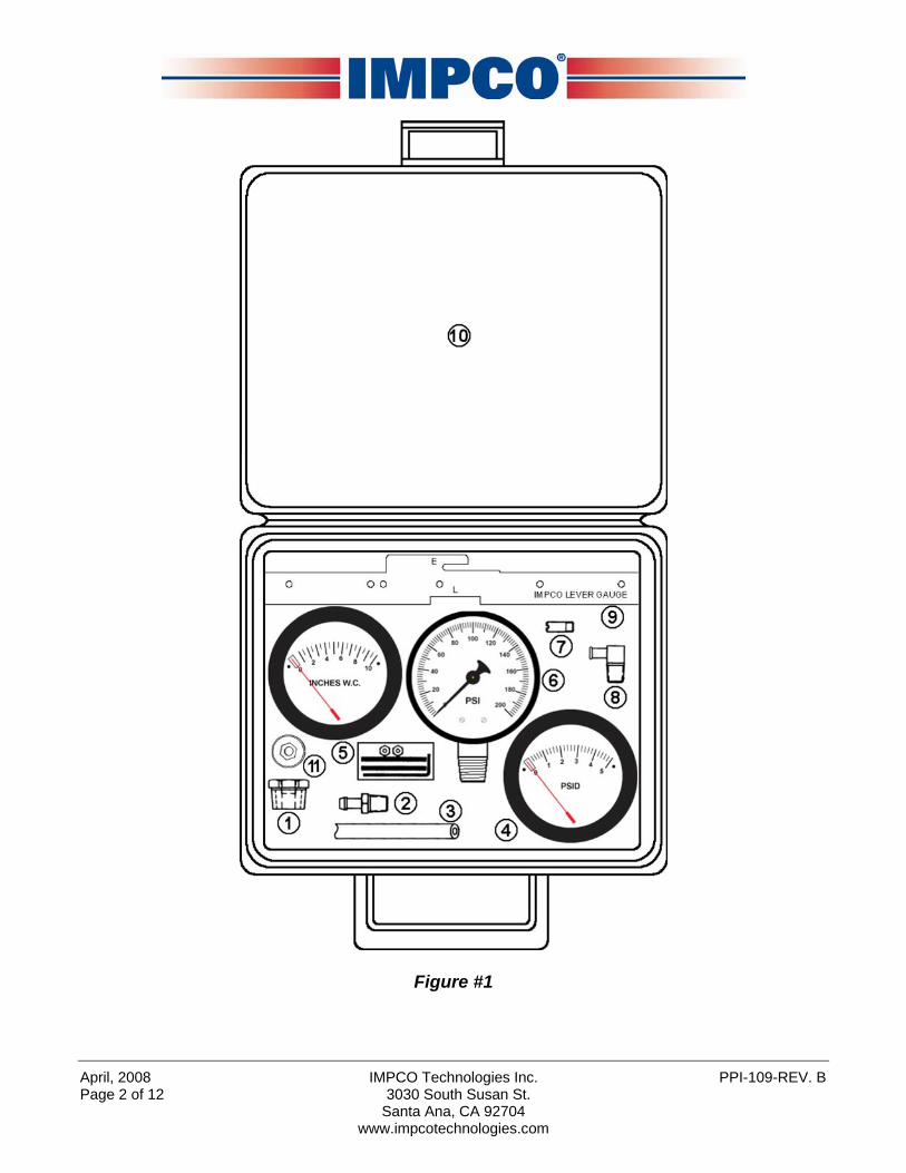
Figure #1
Page 2 of 12 3030 South Susan St. Santa Ana, CA 92704
www.impcotechnologies.com

PPI-109-REV. B IMPCO Technologies Inc. April, 2008 3030 South Susan St. Page 3 of 12 Santa Ana, CA 92704
www.impcotechnologies.com
Chapter I
ITK-1 Test Kit Contents
The ITK-1 Test Kit contains all items listed in table #1. If your kit is missing any component, or has any damaged items, please call your IMPCO distributor for instructions.
ITEM DESCRIPTION QTY USED IMPCO PART NUMBER
1 Bushing, Model J 1 B3-26 2 Fitting, 1/8” NPT / 3/16” HS Nip Brass 1 F4-4 3 Hose, 3/16” ID Vacuum, Bulk 8 feet H1-11 4 Test Kit Gauge, 0-5 PSI 1 TG-005 5 Test Kit Gauge, 0-10” WC 1 TG-010 6 Test Kit Gauge, 200 PSI 1 TG-0200 7 Fitting, ¼ UNF, ¼ HS Vac Nip 1 F4-2 8 Fitting, 1/8” NPT ¼” HS 90O El Nylon 1 F4-8 9 Gauge, Secondary Lever Height 1 G2-2
10 Case, Plastic 1 C9-25849-003 11 Test Plug 1 P3-51214-001 12
(Not Shown) ITK-1 User’s Manual 1 PPI-109
Table #1
April, 2008 IMPCO Technologies Inc. PPI-109-REV. B
Chapter II
Tool Usage Instructions
A. High Pressure Gauge (TG-0200): This pressure gauge is used for input fuel pressure readings. Connectivity depends entirely upon your application. Do not connect the gauge where the delivery pressure will exceed 200 PSI.
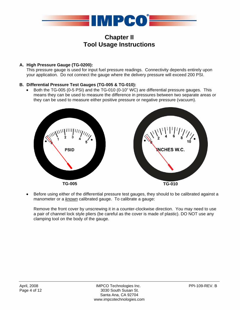
B. Differential Pressure Test Gauges (TG-005 & TG-010): • Both the TG-005 (0-5 PSI) and the TG-010 (0-10” WC) are differential pressure gauges. This
means they can be used to measure the difference in pressures between two separate areas or they can be used to measure either positive pressure or negative pressure (vacuum).
TG-005
TG-010
• Before using either of the differential pressure test gauges, they should to be calibrated against a
manometer or a known calibrated gauge. To calibrate a gauge:
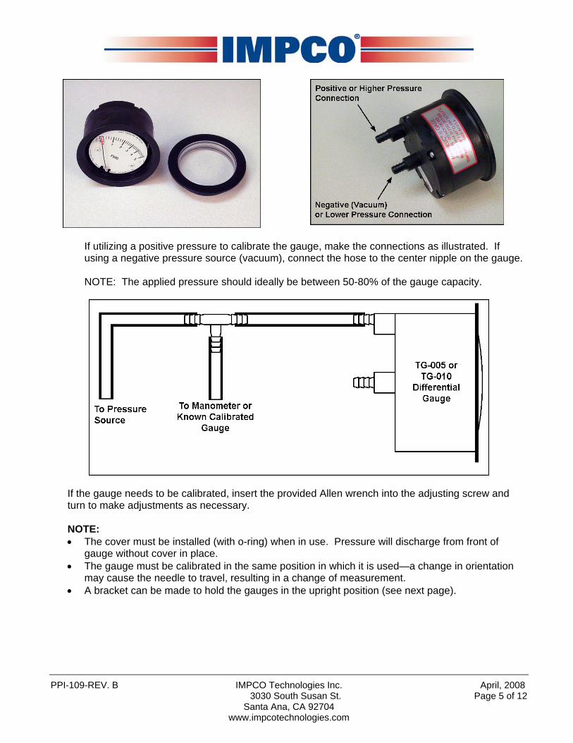
Remove the front cover by unscrewing it in a counter-clockwise direction. You may need to use a pair of channel lock style pliers (be careful as the cover is made of plastic). DO NOT use any clamping tool on the body of the gauge.
Page 4 of 12 3030 South Susan St. Santa Ana, CA 92704
www.impcotechnologies.com
PPI-109-REV. B IMPCO Technologies Inc. April, 2008
If utilizing a positive pressure to calibrate the gauge, make the connections as illustrated. If using a negative pressure source (vacuum), connect the hose to the center nipple on the gauge. NOTE: The applied pressure should ideally be between 50-80% of the gauge capacity.
If the gauge needs to be calibrated, insert the provided Allen wrench into the adjusting screw and turn to make adjustments as necessary. NOTE: • The cover must be installed (with o-ring) when in use. Pressure will discharge from front of
gauge without cover in place. • The gauge must be calibrated in the same position in which it is used—a change in orientation
may cause the needle to travel, resulting in a change of measurement. • A bracket can be made to hold the gauges in the upright position (see next page).
3030 South Susan St. Page 5 of 12 Santa Ana, CA 92704
www.impcotechnologies.com

April, 2008 IMPCO Technologies Inc. PPI-109-REV. B
• Replace the cover, pressurize and compare to known good gauge for accuracy. • Repeat steps as necessary until the gauge is properly calibrated.
NOTE: If a manometer or a known calibrated gauge is not available, make sure the gauge is “zeroed” and the needle is not indicating a pressure or “pinned” when sitting idle. This method usually results in an accuracy within +/- 1.5” w.c.
A properly calibrated TG-010 Gauge
Page 6 of 12 3030 South Susan St. Santa Ana, CA 92704
www.impcotechnologies.com
PPI-109-REV. B IMPCO Technologies Inc. April, 2008
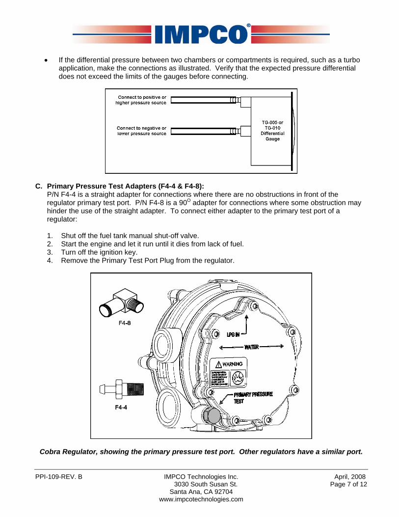
• If the differential pressure between two chambers or compartments is required, such as a turbo
application, make the connections as illustrated. Verify that the expected pressure differential does not exceed the limits of the gauges before connecting.
C. Primary Pressure Test Adapters (F4-4 & F4-8): P/N F4-4 is a straight adapter for connections where there are no obstructions in front of the regulator primary test port. P/N F4-8 is a 90O adapter for connections where some obstruction may hinder the use of the straight adapter. To connect either adapter to the primary test port of a regulator: 1. Shut off the fuel tank manual shut-off valve. 2. Start the engine and let it run until it dies from lack of fuel. 3. Turn off the ignition key. 4. Remove the Primary Test Port Plug from the regulator.
Cobra Regulator, showing the primary pressure test port. Other regulators have a similar port.
3030 South Susan St. Page 7 of 12 Santa Ana, CA 92704
www.impcotechnologies.com
April, 2008 IMPCO Technologies Inc. PPI-109-REV. B
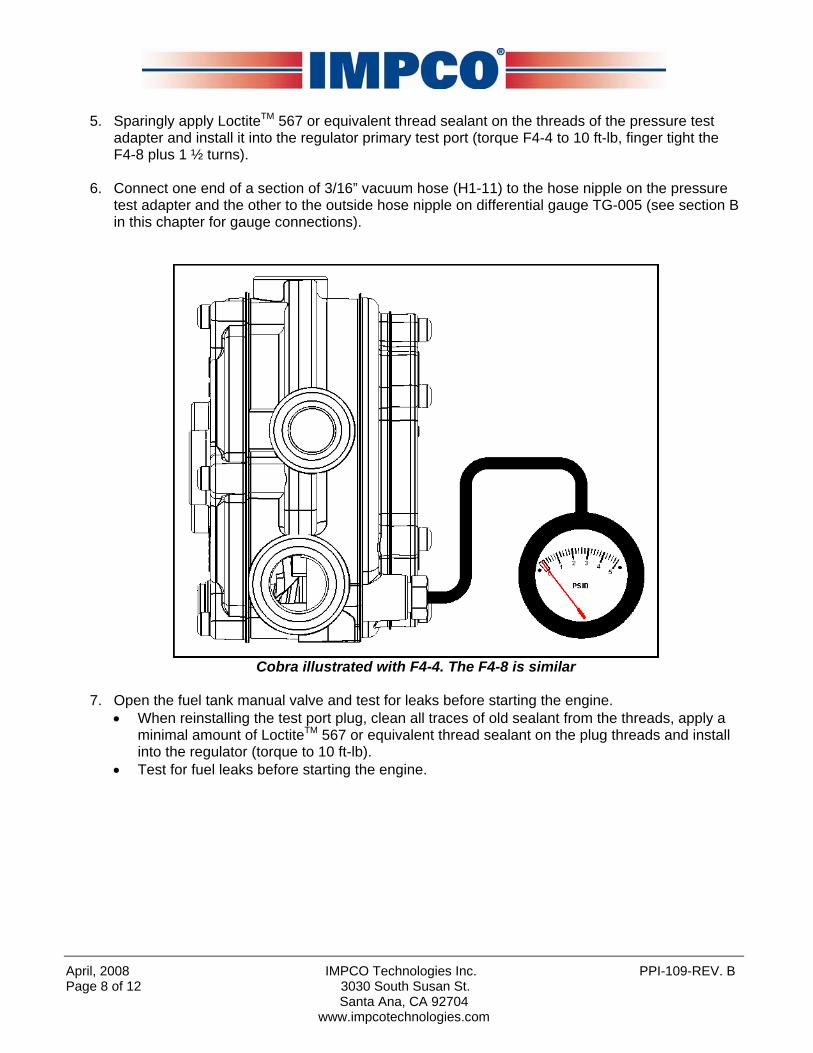
5. Sparingly apply LoctiteTM 567 or equivalent thread sealant on the threads of the pressure test
adapter and install it into the regulator primary test port (torque F4-4 to 10 ft-lb, finger tight the F4-8 plus 1 ½ turns).
6. Connect one end of a section of 3/16” vacuum hose (H1-11) to the hose nipple on the pressure
test adapter and the other to the outside hose nipple on differential gauge TG-005 (see section B in this chapter for gauge connections).
Cobra illustrated with F4-4. The F4-8 is similar
7. Open the fuel tank manual valve and test for leaks before starting the engine.
• When reinstalling the test port plug, clean all traces of old sealant from the threads, apply a minimal amount of LoctiteTM 567 or equivalent thread sealant on the plug threads and install into the regulator (torque to 10 ft-lb).
• Test for fuel leaks before starting the engine.
Page 8 of 12 3030 South Susan St. Santa Ana, CA 92704
www.impcotechnologies.com

PPI-109-REV. B IMPCO Technologies Inc. April, 2008
D. Secondary Lever Height Gauge (G2-2):
The secondary lever height gauge is actually two gauges in one. One side provides the secondary lever heights for the Model E & Model L regulators and the other side has the mounting hole templates for the Model J, L, EV & E regulators and the Model VFF lockoff.
Secondary Lever Height Gauge (G2-2)
To use as a mounting-hole template: The left hole (under the word “COMMON”) is common hole when using the gauge as a mounting template. Locate the hole under the model number of the regulator or lockoff you are using for the other hole. To use as secondary lever height gauge: • Model E:
With the secondary chamber cover off, lay the gauge on the regulator body and slide the slot labeled “E” over the secondary lever pin as illustrated. If the pin will not easily slide into the slot or lifts the gauge up off of the body, remove and carefully bend the lever until it slides in without force and does not lift the gauge. NOTE: Bending the lever in place may result in damage to the seat.
Model “E” Regulator
3030 South Susan St. Page 9 of 12 Santa Ana, CA 92704
www.impcotechnologies.com

April, 2008 IMPCO Technologies Inc. PPI-109-REV. B
• Model L:
With the secondary chamber cover off, lay the gauge on the regulator body with the secondary lever inside the slot labeled “L” as illustrated. The gauge should just contact the secondary lever without being lifted from the body. Make any necessary adjustments by removing and carefully bending the secondary lever. NOTE: Bending the lever in place may result in damage to the seat.
Model “L” Regulator
E. Model “J” Bushing:
The Model “J” bushing is used in conjunction with either the F4-4 or F4-8 pressure test adapter for performing a secondary pressure test on a Model “J” regulator/converter. To perform the test, remove the ½” NPT plug from the unused vapor fuel outlet. Apply a small amount of LoctiteTM 567 or equivalent thread sealant on the bushing threads and install the bushing in the outlet. Then, apply some of the sealant onto the F4-4 or F4-8 pressure adapter and install it into the bushing. Connect the 3/16” vacuum hose to the adapter and the other end of the hose to the proper pressure gauge nipple (depending on fuel type).
Page 10 of 12 3030 South Susan St. Santa Ana, CA 92704
www.impcotechnologies.com
PPI-109-REV. B IMPCO Technologies Inc. April, 2008
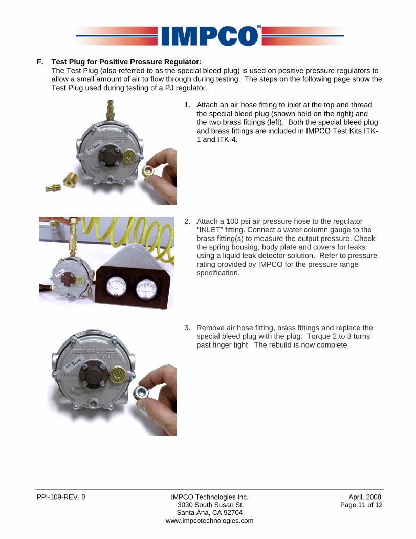
F. Test Plug for Positive Pressure Regulator:
The Test Plug (also referred to as the special bleed plug) is used on positive pressure regulators to allow a small amount of air to flow through during testing. The steps on the following page show the Test Plug used during testing of a PJ regulator.
1. Attach an air hose fitting to inlet at the top and thread the special bleed plug (shown held on the right) and the two brass fittings (left). Both the special bleed plug and brass fittings are included in IMPCO Test Kits ITK-1 and ITK-4.
2. Attach a 100 psi air pressure hose to the regulator "INLET" fitting. Connect a water column gauge to the brass fitting(s) to measure the output pressure. Check the spring housing, body plate and covers for leaks using a liquid leak detector solution. Refer to pressure rating provided by IMPCO for the pressure range specification.
3. Remove air hose fitting, brass fittings and replace the
special bleed plug with the plug. Torque 2 to 3 turns past finger tight. The rebuild is now complete.
3030 South Susan St. Page 11 of 12 Santa Ana, CA 92704
www.impcotechnologies.com
April, 2008 IMPCO Technologies Inc. PPI-109-REV. B Page 12 of 12 3030 South Susan St.
Santa Ana, CA 92704 www.impcotechnologies.com
WARNING: IMPROPER INSTALLATION OR USE OF THIS PRODUCT MAY CAUSE
SERIOUS INJURY AND/OR PROPERTY DAMAGE. SERVICE TECHNICIANS AND USERS SHOULD CAREFULLY READ AND ABIDE BY THE PROVISIONS SET FORTH IN NATIONAL FIRE PROTECTION ASSOCIATION PAMPHLET #37 FOR STATIONARY ENGINES, #52 FOR CNG VEHICULAR FUEL SYSTEMS OR #58 FOR LPG SYSTEMS. INSTALLERS LPG INSTALLATIONS IN THE UNITED STATES MUST BE DONE IN ACCORDANCE WITH FEDERAL STATE OR LOCAL LAW, WHICHEVER IS APPLICABLE AND NATIONAL FIRE PROTECTION ASSOCIATION PAMPHLET #58, STANDARD FOR STORAGE AND HANDLING OF LIQUEFIED PETROLEUM GASES TO THE EXTENT THESE STANDARDS ARE NOT IN VIOLATION WITH FEDERAL, STATE OR LOCAL LAW. IN CANADA REFER TO CAN/CGA PROPANE INSTALLATION CODES. CNG INSTALLATIONS IN THE UNITED STATES MUST RE DONE IN ACCORDANCE WITH FEDERAL STATE OR LOCAL LAW AND NATIONAL FIRE PROTECTION ASSOCIATION PAMPHLET #52, COMPRESSED NATURAL GAS (CNG) VEHICULAR FUEL SYSTEMS TO THE EXTENT THESE STANDARDS ARE NOT IN VIOLATION WITH FEDERAL, STATE OR LOCAL LAW. IN CANADA REFER TO CAN/CGA CNG INSTALLATION CODES. LPG AND/OR NATURAL GAS INSTALLATIONS ON STATIONARY ENGINES MUST RE DONE IN ACCORDANCE WITH FEDERAL, STATE OR LOCAL LAW AND NATIONAL FIRE PROTECTION ASSOCIATION PAMPHLET #37, STATIONARY COMBUSTION ENGINES AND GAS TURBINE ENGINES, TO THE EXTENT THESE STANDARDS ARE NOT IN VIOLATION WITH FEDERAL, STATE OR LOCAL LAW. FAILURE TO ABIDE BY THE ABOVE WILL VOID ANY IMPCO WARRANTY ON THE PRODUCTS AND MAY CAUSE SERIES INJURY OR PROPERTY DAMAGE. DUE TO THE INHERENT DANGER OF GASEOUS FUELS THE IMPCO PRODUCTS SHOULD NOT BE INSTALLED OR USED BY PERSONS NOT KNOWLEDGEABLE OF THE HAZARDS ASSOCIATED WITH THE USE OF GASEOUS FUELS.


