International Telecommunication Union ITU-T G.984.4 TELECOMMUNICATION STANDARDIZATION SECTOR OF ITU (02/2008) SERIES G: TRANSMISSION SYSTEMS AND MEDIA, DIGITAL SYSTEMS AND NETWORKS Digital sections and digital line system – Optical line systems for local and access networks Gigabit-capable Passive Optical Networks (G-PON): ONT management and control interface specification Recommendation ITU-T G.984.4
Transcript
I n t e r n a t i o n a l T e l e c o m m u n i c a t i o n U n i o n
ITU-T G.984.4TELECOMMUNICATION STANDARDIZATION SECTOR OF ITU
(02/2008)
SERIES G: TRANSMISSION SYSTEMS AND MEDIA, DIGITAL SYSTEMS AND NETWORKS Digital sections and digital line system – Optical line systems for local and access networks
Gigabit-capable Passive Optical Networks (G-PON): ONT management and control interface specification
Recommendation ITU-T G.984.4
ITU-T G-SERIES RECOMMENDATIONS TRANSMISSION SYSTEMS AND MEDIA, DIGITAL SYSTEMS AND NETWORKS
INTERNATIONAL TELEPHONE CONNECTIONS AND CIRCUITS G.100–G.199 GENERAL CHARACTERISTICS COMMON TO ALL ANALOGUE CARRIER-TRANSMISSION SYSTEMS
G.200–G.299
INDIVIDUAL CHARACTERISTICS OF INTERNATIONAL CARRIER TELEPHONE SYSTEMS ON METALLIC LINES
G.300–G.399
GENERAL CHARACTERISTICS OF INTERNATIONAL CARRIER TELEPHONE SYSTEMS ON RADIO-RELAY OR SATELLITE LINKS AND INTERCONNECTION WITH METALLIC LINES
G.400–G.449
COORDINATION OF RADIOTELEPHONY AND LINE TELEPHONY G.450–G.499 TRANSMISSION MEDIA AND OPTICAL SYSTEMS CHARACTERISTICS G.600–G.699 DIGITAL TERMINAL EQUIPMENTS G.700–G.799 DIGITAL NETWORKS G.800–G.899 DIGITAL SECTIONS AND DIGITAL LINE SYSTEM G.900–G.999
General G.900–G.909 Parameters for optical fibre cable systems G.910–G.919 Digital sections at hierarchical bit rates based on a bit rate of 2048 kbit/s G.920–G.929 Digital line transmission systems on cable at non-hierarchical bit rates G.930–G.939 Digital line systems provided by FDM transmission bearers G.940–G.949 Digital line systems G.950–G.959 Digital section and digital transmission systems for customer access to ISDN G.960–G.969 Optical fibre submarine cable systems G.970–G.979 Optical line systems for local and access networks G.980–G.989 Access networks G.990–G.999
QUALITY OF SERVICE AND PERFORMANCE – GENERIC AND USER-RELATED ASPECTS
G.1000–G.1999
TRANSMISSION MEDIA CHARACTERISTICS G.6000–G.6999 DATA OVER TRANSPORT – GENERIC ASPECTS G.7000–G.7999 PACKET OVER TRANSPORT ASPECTS G.8000–G.8999 ACCESS NETWORKS G.9000–G.9999
For further details, please refer to the list of ITU-T Recommendations.
Rec. ITU-T G.984.4 (02/2008) i
Recommendation ITU-T G.984.4
Gigabit-capable Passive Optical Networks (G-PON): ONT management and control interface specification
Summary Recommendation ITU-T G.984.4 provides the optical network termination (ONT) management and control interface (OMCI) specification for gigabit-capable passive optical network (G-PON) systems as defined in Recommendations ITU-T G.984.2 and G.984.3.
Firstly, it specifies the managed entities of a protocol-independent management information base (MIB) that models the exchange of information between the optical line termination (OLT) and the optical network termination (ONT). In addition, it covers the ONT management and control channel, protocol and detailed messages. This revised version incorporates the material from Amendment 1 (2005), Amendment 2 (2006), and Amendment 3 (2006).
In addition to the purely editorial collection work, this revision endeavours to remove all references to the optional ATM transport capabilities of G-PON, since all modern systems do not support it.
Source Recommendation ITU-T G.984.4 was approved on 22 February 2008 by ITU-T Study Group 15 (2005-2008) under Recommendation ITU-T A.8 procedure.
This edition includes additions and corrections approved on 29 March 2008 by ITU-T Study Group 15 (2005-2008) under the Recommendation ITU-T A.8 procedure.
ii Rec. ITU-T G.984.4 (02/2008)
FOREWORD
The International Telecommunication Union (ITU) is the United Nations specialized agency in the field of telecommunications, information and communication technologies (ICTs). The ITU Telecommunication Standardization Sector (ITU-T) is a permanent organ of ITU. ITU-T is responsible for studying technical, operating and tariff questions and issuing Recommendations on them with a view to standardizing telecommunications on a worldwide basis.
The World Telecommunication Standardization Assembly (WTSA), which meets every four years, establishes the topics for study by the ITU-T study groups which, in turn, produce Recommendations on these topics.
The approval of ITU-T Recommendations is covered by the procedure laid down in WTSA Resolution 1.
In some areas of information technology which fall within ITU-T's purview, the necessary standards are prepared on a collaborative basis with ISO and IEC.
NOTE
In this Recommendation, the expression "Administration" is used for conciseness to indicate both a telecommunication administration and a recognized operating agency.
Compliance with this Recommendation is voluntary. However, the Recommendation may contain certain mandatory provisions (to ensure e.g. interoperability or applicability) and compliance with the Recommendation is achieved when all of these mandatory provisions are met. The words "shall" or some other obligatory language such as "must" and the negative equivalents are used to express requirements. The use of such words does not suggest that compliance with the Recommendation is required of any party.
INTELLECTUAL PROPERTY RIGHTS
ITU draws attention to the possibility that the practice or implementation of this Recommendation may involve the use of a claimed Intellectual Property Right. ITU takes no position concerning the evidence, validity or applicability of claimed Intellectual Property Rights, whether asserted by ITU members or others outside of the Recommendation development process.
As of the date of approval of this Recommendation, ITU had received notice of intellectual property, protected by patents, which may be required to implement this Recommendation. However, implementers are cautioned that this may not represent the latest information and are therefore strongly urged to consult the TSB patent database at http://www.itu.int/ITU-T/ipr/.
6 Reference model and terms .......................................................................................... 10 6.1 OMCI in Recommendation ITU-T G.984.1 ................................................... 10 6.2 ONT functions ................................................................................................ 10 6.3 Encapsulation in GEM frame ......................................................................... 11 6.4 Support of multicast connection..................................................................... 11 6.5 Voice over IP management ............................................................................ 11
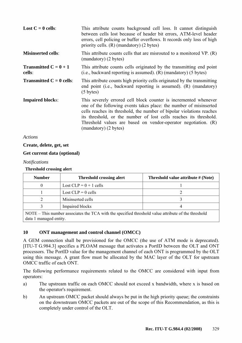
10 ONT management and control channel (OMCC)......................................................... 329
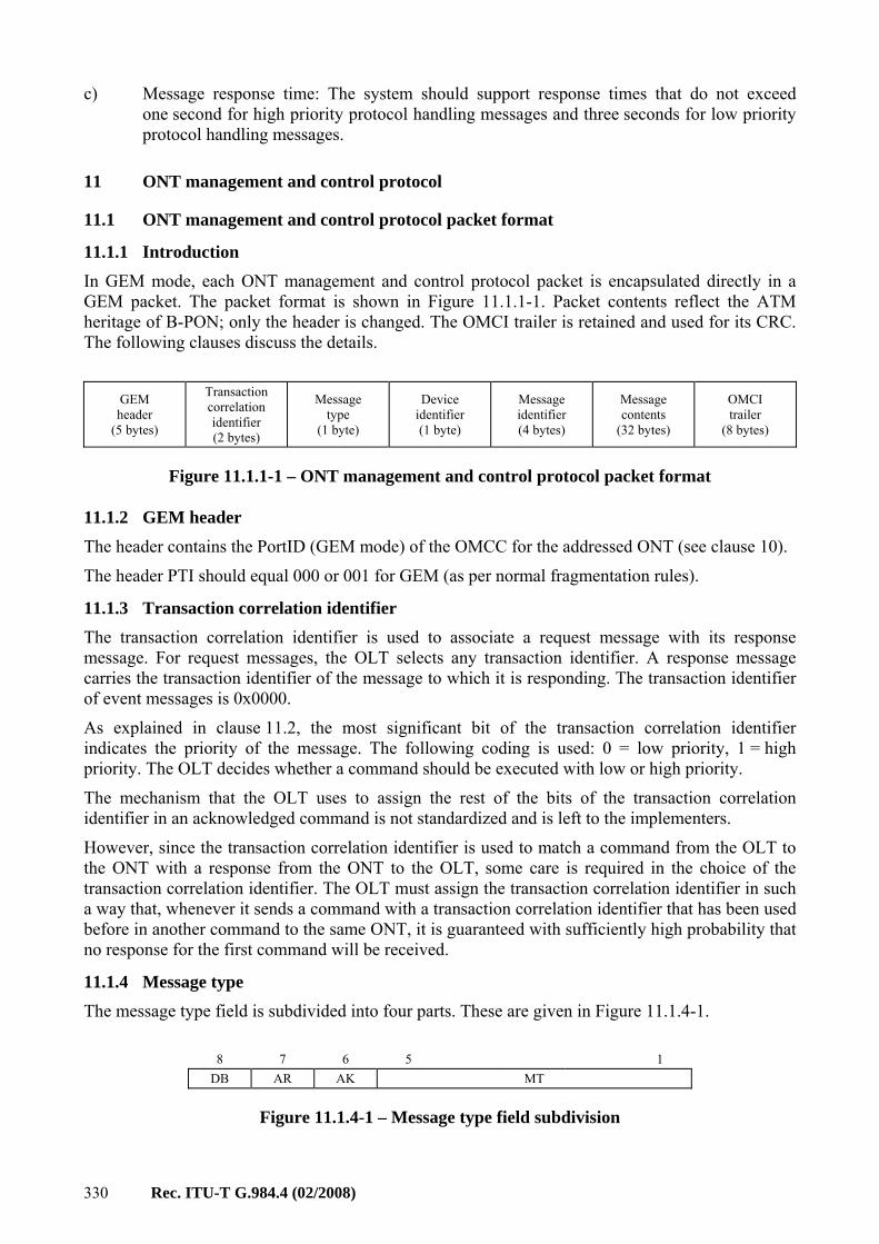
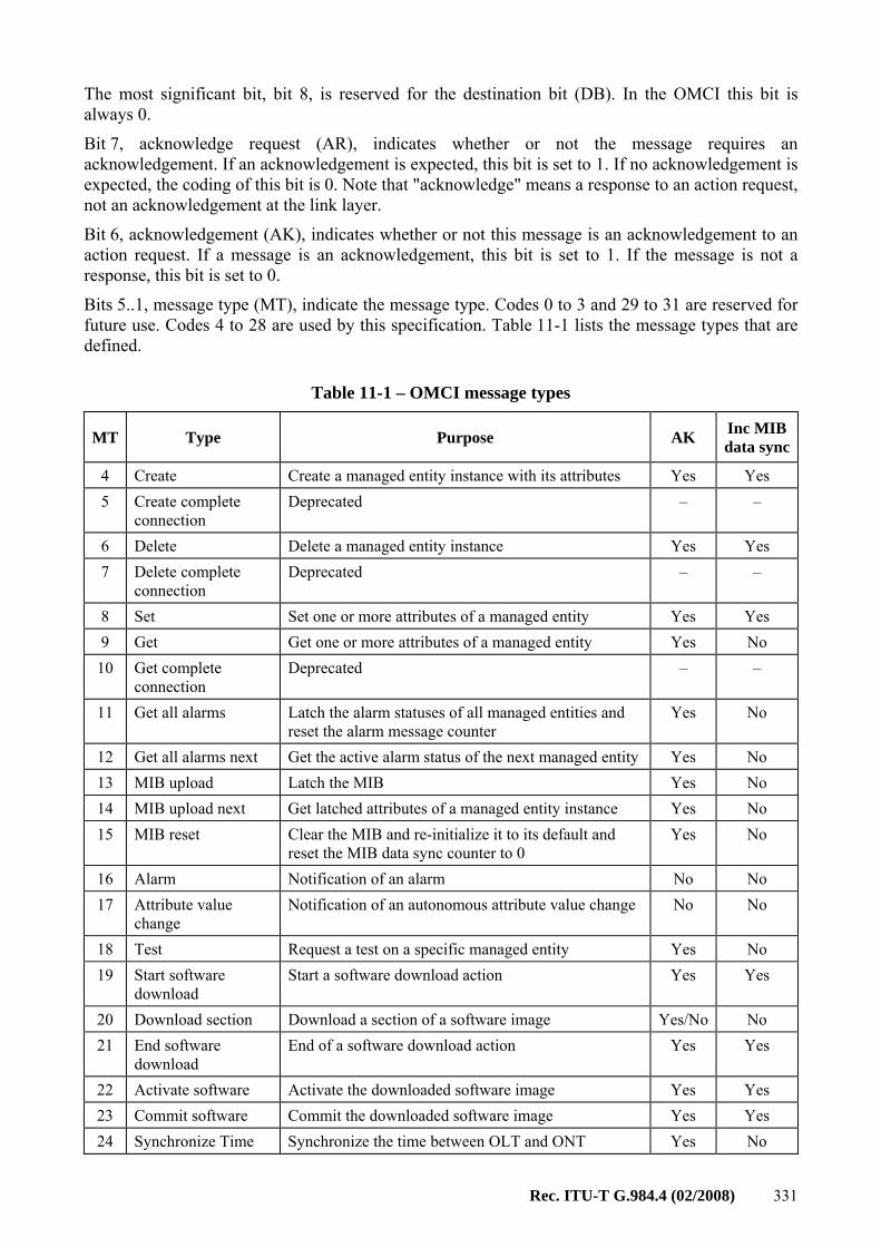
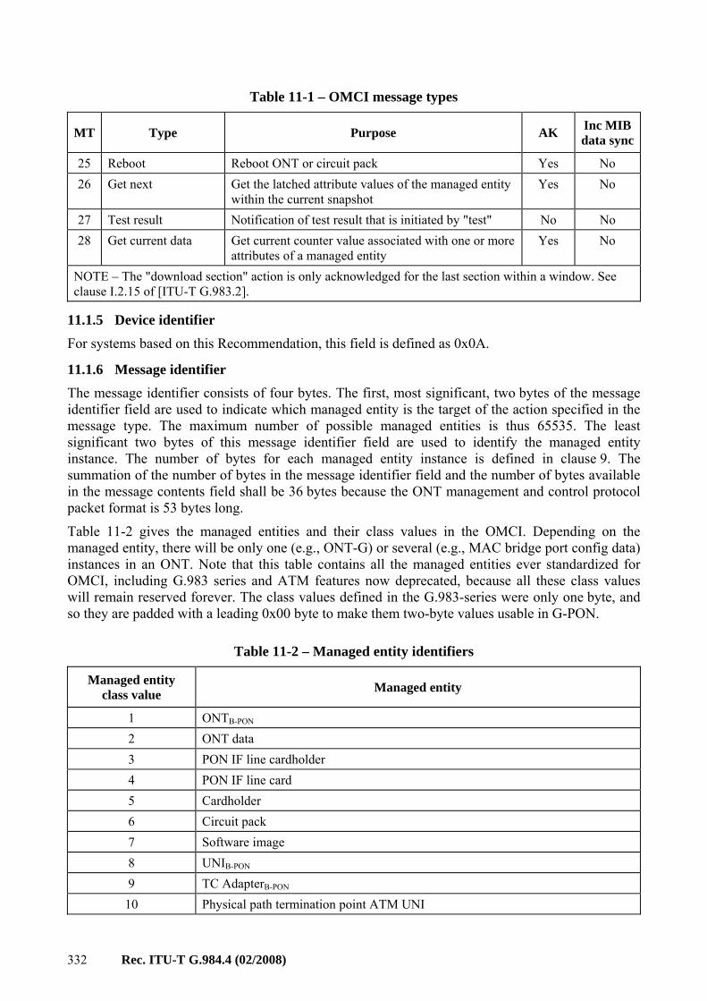
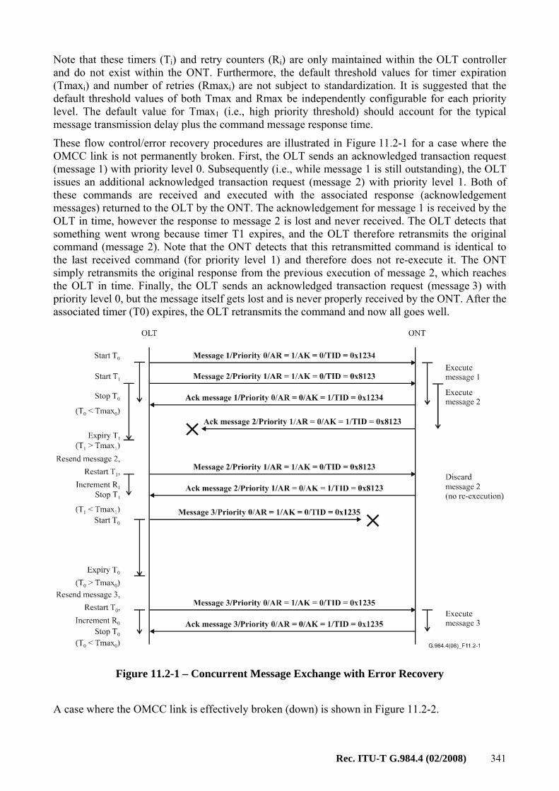
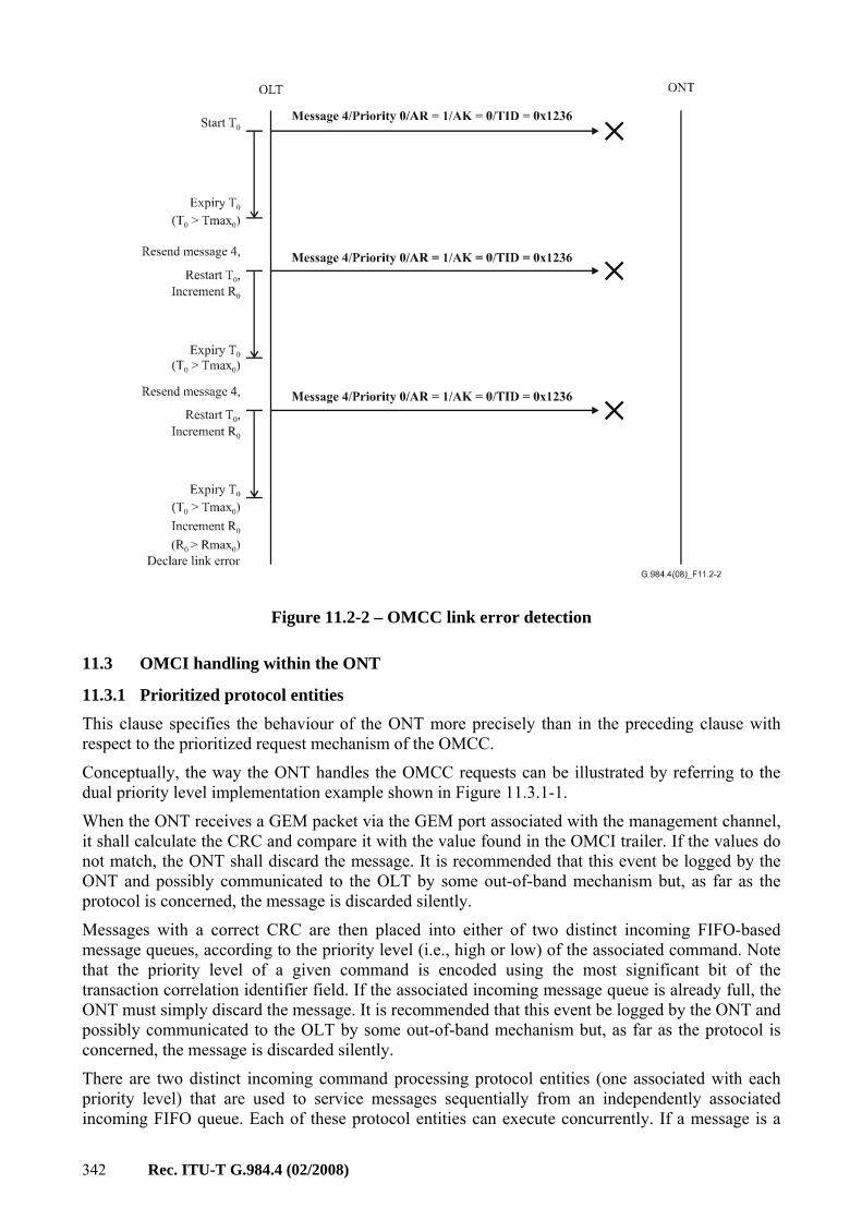
11 ONT management and control protocol ....................................................................... 330 11.1 ONT management and control protocol packet format .................................. 330 11.2 Message flow control and error recovery....................................................... 340
iv Rec. ITU-T G.984.4 (02/2008)
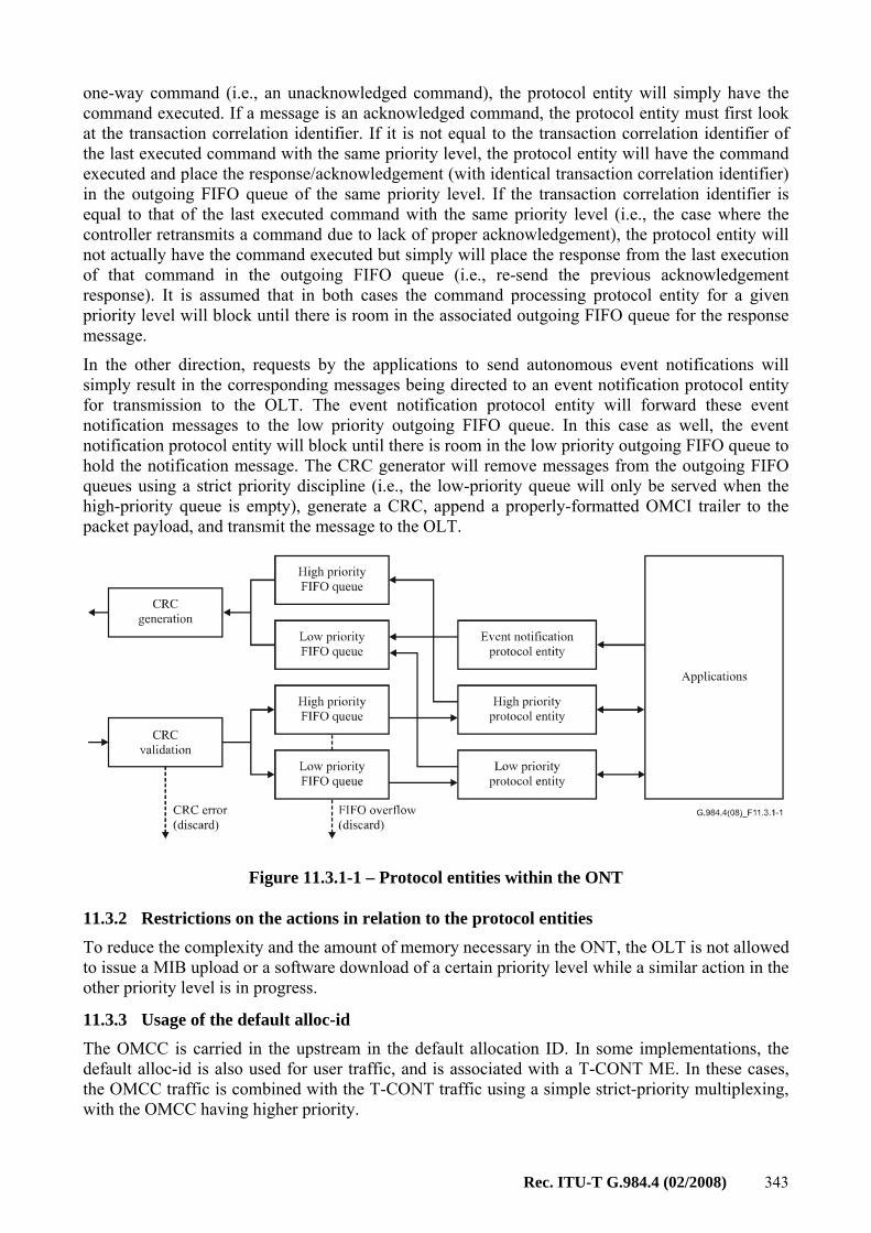
Page 11.3 OMCI handling within the ONT .................................................................... 342
Appendix I – OMCI common mechanisms and services......................................................... 344 I.1 Common mechanisms .................................................................................... 344 I.2 Common services ........................................................................................... 355
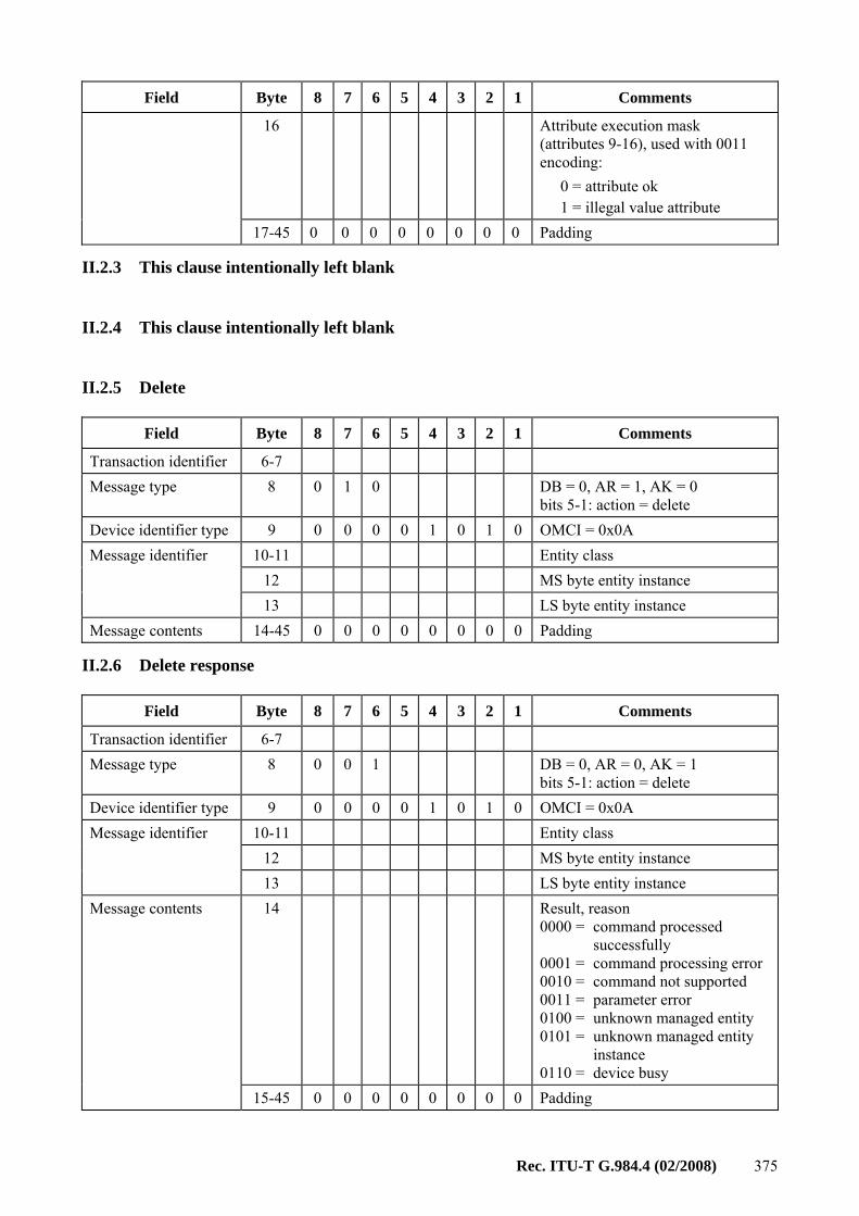
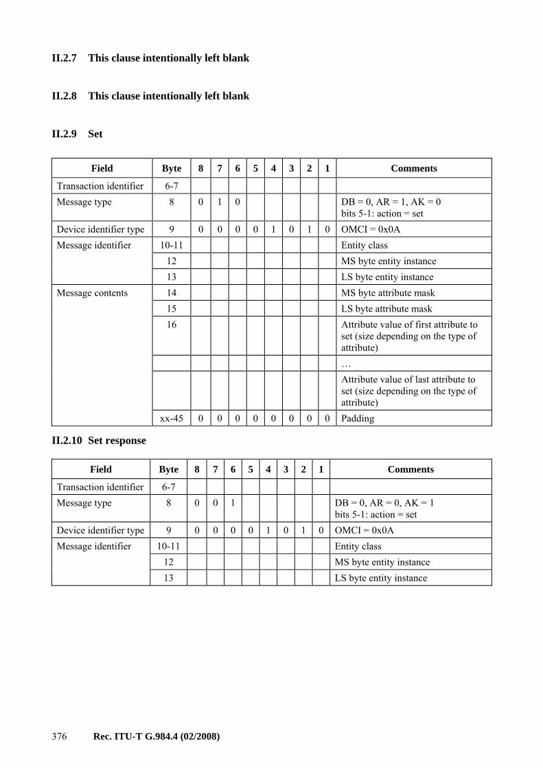
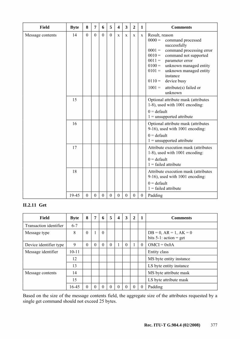
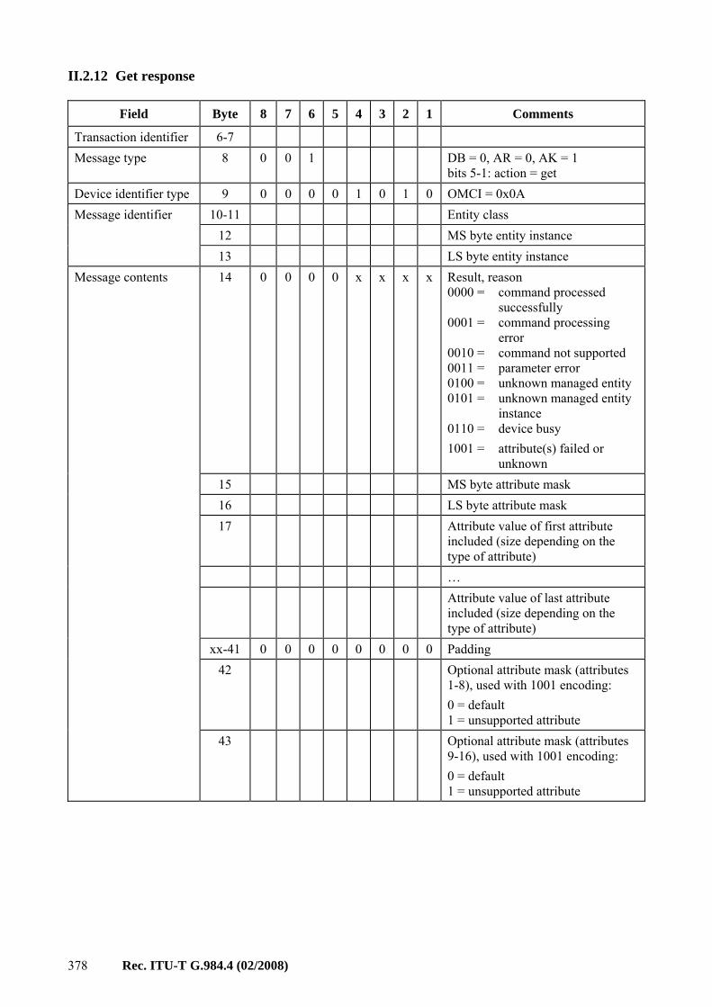
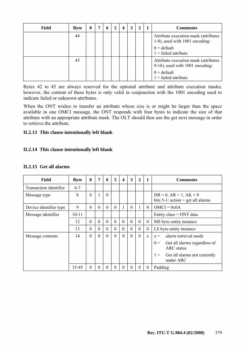
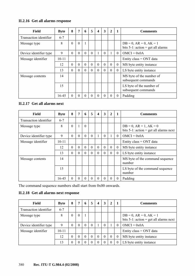
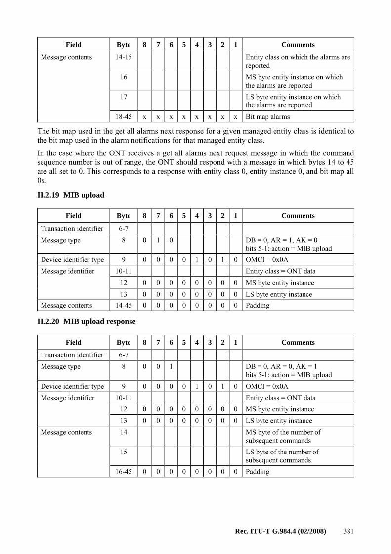
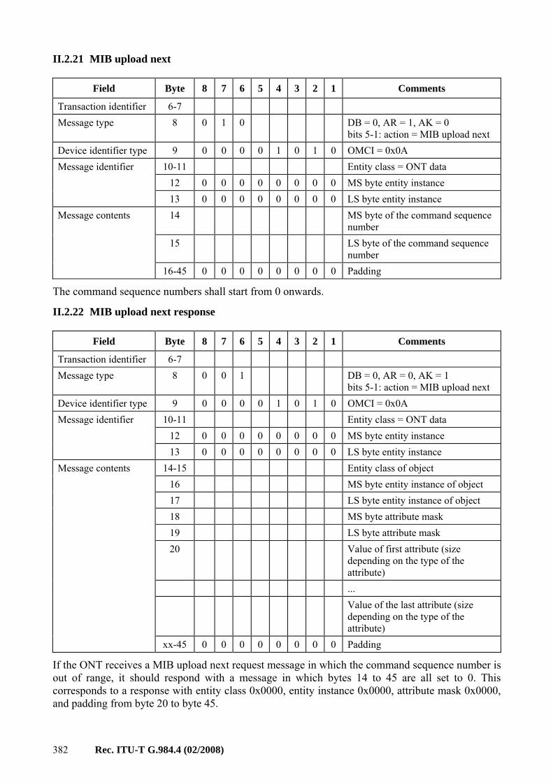
Appendix II – OMCI message set............................................................................................ 371 II.1 General remarks.............................................................................................. 371 II.2 Message layout ............................................................................................... 373
Gigabit-capable Passive Optical Networks (G-PON): ONT management and control interface specification
1 Scope This Recommendation specifies the optical network termination management and control interface (OMCI) for the G-PON system defined in [ITU-T G.984.2] and [ITU-T G.984.3] to enable multi-vendor interoperability between the optical line termination (OLT) and the ONT.
The OMCI specification addresses the ONT configuration management, fault management and performance management for G-PON system operation and for several services, including: • asynchronous transfer mode (ATM) adaptation layer 5; • G-PON encapsulation method (GEM) adaptation layers; • circuit emulation service; • Ethernet services, including MAC bridged LAN; • voice services; • wavelength division multiplexing.
The focus of this OMCI specification is on Fibre to the home (FTTH) and Fibre to the business (FTTBusiness) ONTs; however, support for optical network units (ONUs) is addressed as well. This Recommendation defines a protocol necessary to support the capabilities identified for these ONTs. It also allows optional components and future extensions.
2 References1 The following ITU-T Recommendations and other references contain provisions which, through reference in this text, constitute provisions of this Recommendation. At the time of publication, the editions indicated were valid. All Recommendations and other references are subject to revision; users of this Recommendation are therefore encouraged to investigate the possibility of applying the most recent edition of the Recommendations and other references listed below. A list of the currently valid ITU-T Recommendations is regularly published. The reference to a document within this Recommendation does not give it, as a stand-alone document, the status of a Recommendation.
[ITU-T G.707] Recommendation ITU-T G.707/Y.1322 (2007), Network node interface for the synchronous digital hierarchy (SDH).
[ITU-T G.728] Recommendation ITU-T G.728 (1992), Coding of speech at 16 kbit/s using low-delay code excited linear prediction.
[ITU-T G.729] Recommendation ITU-T G.729 (2007), Coding of speech at 8 kbit/s using conjugate-structure algebraic-code-excited linear prediction (CS-ACELP).
[ITU-T M.3100] Recommendation ITU-T M.3100 (2005), Generic network information model.
[ITU-T T.35] Recommendation ITU-T T.35 (2000), Procedure for the allocation of ITU-T defined codes for non-standard facilities.
[ITU-T T.38] Recommendation ITU-T T.38 (2005), Procedures for real-time Group 3 facsimile communication over IP networks.
Rec. ITU-T G.984.4 (02/2008) 3
[ATIS-0322000] ATIS-0322000 (2005), Representation of the Communications Industry Manufacturers, Suppliers, and Related Service Companies for Information Exchange. <http://webstore.ansi.org/RecordDetail.aspx?sku=ATIS-0322000.2005>
[ANSI T1.PP.413] ANSI T1.PP.413* (2004), Network to Customer Installation Interfaces - Asymmetric Digital Subscriber Line (ADSL) Metallic Interface. <http://webstore.ansi.org/RecordDetail.aspx?sku=T1.PP.413-2004>
[ETSI 101 270-1] ETSI TS 101 270-1 V1.4.1 (2005), Transmission and Multiplexing (TM); Access transmission systems on metallic access cables; Very high speed Digital Subscriber Line (VDSL); Part 1: Functional requirements. <http://webapp.etsi.org/workprogram/Report_WorkItem.asp?WKI_ID=19789>
[ETSI 101 388] ETSI TS 101 388 V1.4.1 (2007), Access Terminals Transmission and Multiplexing (ATTM); Access transmission systems on metallic access cables; Asymmetric Digital Subscriber Line (ADSL) – European specific requirements. <http://webapp.etsi.org/workprogram/Report_WorkItem.asp?WKI_ID=27082>
[IEEE 802] IEEE 802-2001, IEEE Standard for local and metropolitan area networks − Overview and Architecture. <http://standards.ieee.org/getieee802/download/802-2001.pdf>
[IEEE 802.1D] IEEE 802.1D-2004, IEEE Standard for local and metropolitan area networks − Media access control (MAC) Bridges. <http://standards.ieee.org/getieee802/download/802.1D-2004.pdf>
[IEEE 802.1Q] IEEE 802.1Q-2005, IEEE Standard for local and metropolitan area networks − Virtual Bridged Local Area Networks. <http://standards.ieee.org/getieee802/download/802.1Q-2005.pdf>
[IEEE 802.11] IEEE 802.11-2007, IEEE Standard for local and metropolitan area networks − Specific requirements − Part 11: Wireless LAN Medium Access Control (MAC) and Physical Layer (PHY) Specifications. <http://standards.ieee.org/getieee802/802.11.html>
[IETF RFC 2833] IETF RFC 2833 (2000), RTP Payload for DTMF Digits, Telephony Tones and Telephony Signals. <http://www.ietf.org/rfc/rfc2833.txt>
[IETF RFC 3551] IETF RFC 3551 (2003), RTP Profile for Audio and Video Conferences with Minimal Control. <http://www.ietf.org/rfc/rfc3551.txt>
[IETF RFC 4733] IETF RFC 4733 (2006), RTP Payload for DTMF Digits, Telephony Tones, and Telephony Signals. <http://www.ietf.org/rfc/rfc4733.txt>
[IETF RFC 4734] IETF RFC 4734 (2006), Definition of Events for Modem, Fax, and Text Telephony Signals. <http://www.ietf.org/rfc/rfc4734.txt>
[DSLF TR-69] DSLF TR-69 (2007), CPE WAN Management Protocol. <http://www.broadband-forum.org/technical/download/TR-069.pdf>
[MEF8] Metro Ethernet Forum MEF8 (2004), Implementation Agreement for the Emulation of PDH Circuits over Metro Ethernet Networks. <http://metroethernetforum.org/PDFs/Standards/MEF8.pdf>
[SCTE 55-1] ANSI/SCTE 55-1 (2002), Digital Broadband Delivery System: Out Of Band Transport Part 1: Mode A. <http://www.scte.org/documents/pdf/ANSISCTE5512002DVS178.pdf>
[SCTE 55-2] ANSI/SCTE 55-2 (2002), Digital Broadband Delivery System: Out Of Band Transport Part 2: Mode B. <http://www.scte.org/documents/pdf/ANSISCTE5522002DVS167.pdf>
3 Definitions This Recommendation defines the following terms:
3.1 downstream: Downstream is a traffic flow from OLT to ONT.
3.2 optical network termination (ONT): A single subscriber device that terminates any one of the distributed (leaf) endpoints of an ODN, implements a PON protocol, and adapts PON PDUs to subscriber service interfaces. An ONT is a special case of an ONU.
3.3 optical network unit (ONU): A generic term denoting a device that terminates any one of the distributed (leaf) endpoints of an ODN, implements a PON protocol, and adapts PON PDUs to subscriber service interfaces. In some contexts, an ONU implies a multiple subscriber device. NOTE – This Recommendation uses the term ONT to refer to either configuration unless a distinction is necessary.
3.4 upstream: The upstream is a traffic flow from ONT to OLT.
4 Abbreviations and acronyms This Recommendation uses the following abbreviations and acronyms:
AAL Asynchronous transfer mode Adaptation Layer
ADSL Asymmetric Digital Subscriber Line (note that the xDSL MEs include the G.992 family as well as G.993.2 VDSL2, but not G.993.1 VDSL)
MMPDU Media access control Management Protocol Data Unit
MoCA Multimedia over Coax Alliance
MPDU Media access control Protocol Data Unit
MSB Most Significant Bit
MSDU Media access control Service Data Unit
MT Message Type
MTU Maximum Transmission Unit
MUX Multiplexing
NMS Network Management System
NSCds Number of SubCarriers – downstream
NSCus Number of SubCarriers – upstream
NT Network Terminal
OAN Optical Access Network
ODN Optical Distribution Network
OLT Optical Line Terminal
OMCC Optical network termination Management and Control Channel
OMCI Optical network termination Management and Control Interface
ONT Optical Network Termination
ONU Optical Network Unit
OpS Operations System
PCF Point Coordination Function
PHY Physical interface
PIR Peak Information Rate
PLCP Physical Layer Convergence Protocol
PLOAM Physical Layer Operations, Administration and Maintenance
PM Performance Monitoring
8 Rec. ITU-T G.984.4 (02/2008)
PMD Physical Medium Dependent
PMS-TC Physical Media Specific – Transmission Convergence
PON Passive Optical Network
POTS Plain Old Telephone Service
PPTP Physical Path Termination Point
PSD Power Spectral Density
PSN Packet Switched Network
PVC Permanent Virtual Circuit
QoS Quality of Service
RDI Remote Defect Indication
RF Radio Frequency
RFI Radio Frequency Interference
RM Resource Management
RTCP Real-time Transport Control Protocol
RTP Real Time Protocol
RTS Request To Send
SAR Segmentation And Reassembly
SCM Single Carrier Modulation
SES Severely Errored Second
SIFS Short Interframe Space
SIP Session Initiation Protocol
SME Station Management Entity
SN Service Node
SNI Service Node Interface
SNR Signal-to-Noise Ratio
SSCS Service Specific Convergence Sublayer
STA Station
TC Transmission Convergence
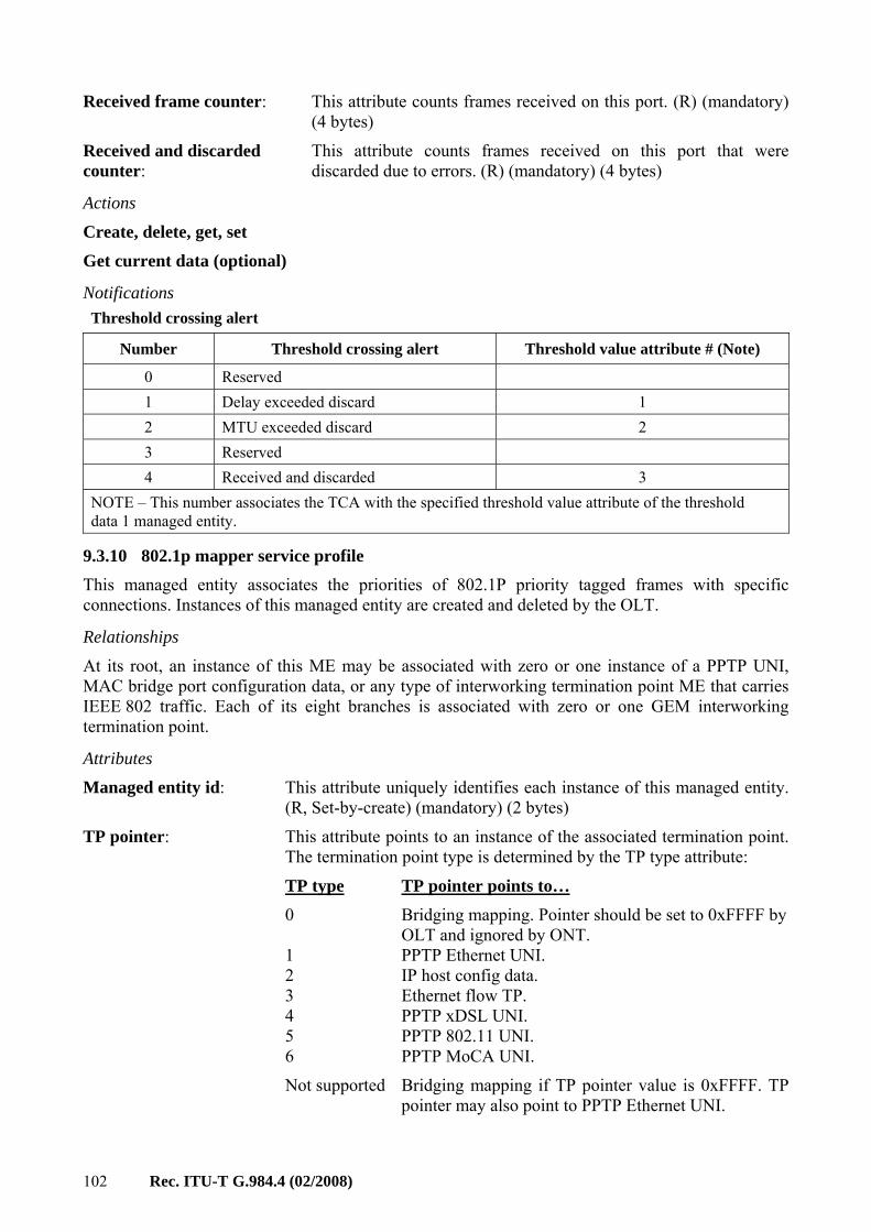
TCA Threshold Crossing Alert
TCI Tag Control Information
T-CONT Transmission Container
TCP Transmission Control Protocol
TDM Time Division Multiplex
TE Terminal Equipment
TOS Type of Service
TP Termination Point
TU Time Unit
Rec. ITU-T G.984.4 (02/2008) 9
TU Tributary Unit
UAS UnAvailable Second
UDP User Datagram Protocol
UNI User Network Interface
UPC Usage Parameter Control
VBR Variable Bit Rate
VC Virtual Circuit
VC Virtual Container (synchronous digital hierarchy)
VCC Virtual Circuit Connection
VCI Virtual Circuit Identifier
VDSL Very high speed Digital Subscriber Line (note that G.993.2 VDSL2 is managed under the xDSL family of MEs)
VID Virtual Local Area Network Identifier
VLAN Virtual Local Area Network
VoIP Voice over Internet Protocol
VP Virtual Path
VPC Virtual Path Connection
VPI Virtual Path Identifier
VRP Video Return Path
VTU-O Very high speed Digital Subscriber Line Transceiver Unit, Optical network termination end
VTU-R Very high speed Digital Subscriber Line Transceiver Unit, Remote terminal end
WEP Wired Equivalent Privacy
WRR Weighted Round Robin
xDSL x Digital Subscriber Line
xTU-C x digital subscriber line Transceiver Unit at the Central office end (in the case of PON, the ONT), used as a generic term referring to both the ATU-C of Recommendations ITU-T G.992.x-series and the VTU-O of Recommendation ITU-T G.993.2.
xTU-R x digital subscriber line Transceiver Unit at the Remote end (subscriber premises), used as a generic term referring to both the ATU-R of Recommendations ITU-T G.992.x-series and the VTU-R of Recommendation ITU-T G.993.2.
5 Conventions In all bit vectors indicated in this Recommendation, the rightmost bit is bit 1. This represents the least significant bit, while bit 8 represents the most significant bit within a byte. If the bit vector is made up of more than one byte, then the numbering starts from the least significant byte onwards.
In all attribute descriptions that refer to the Boolean values "true" and "false," true is coded as 0x01 in hexadecimal and false is coded as 0.
10 Rec. ITU-T G.984.4 (02/2008)
In all attribute descriptions that refer to spaces, the value 0x20 must be used for the entire size of the attribute.
"ASCII string" is a sequence of ASCII encoded characters, terminated by the NULL character (0x00). If a string occupies the entire allocated size of an attribute, the terminating null is not required.
6 Reference model and terms
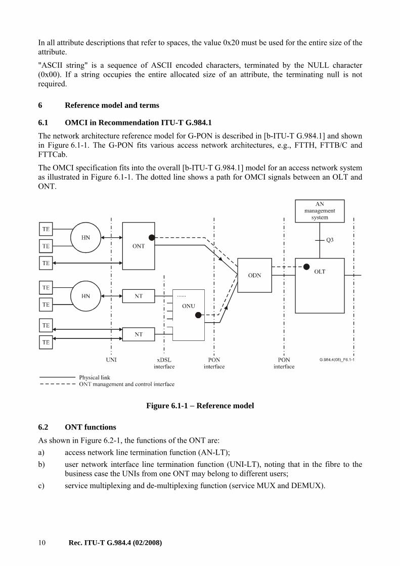
6.1 OMCI in Recommendation ITU-T G.984.1 The network architecture reference model for G-PON is described in [b-ITU-T G.984.1] and shown in Figure 6.1-1. The G-PON fits various access network architectures, e.g., FTTH, FTTB/C and FTTCab.
The OMCI specification fits into the overall [b-ITU-T G.984.1] model for an access network system as illustrated in Figure 6.1-1. The dotted line shows a path for OMCI signals between an OLT and ONT.
Figure 6.1-1 − Reference model
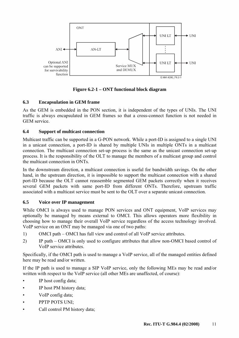
6.2 ONT functions As shown in Figure 6.2-1, the functions of the ONT are: a) access network line termination function (AN-LT); b) user network interface line termination function (UNI-LT), noting that in the fibre to the
business case the UNIs from one ONT may belong to different users; c) service multiplexing and de-multiplexing function (service MUX and DEMUX).
Rec. ITU-T G.984.4 (02/2008) 11
Figure 6.2-1 – ONT functional block diagram
6.3 Encapsulation in GEM frame As the GEM is embedded in the PON section, it is independent of the types of UNIs. The UNI traffic is always encapsulated in GEM frames so that a cross-connect function is not needed in GEM service.
6.4 Support of multicast connection Multicast traffic can be supported in a G-PON network. While a port-ID is assigned to a single UNI in a unicast connection, a port-ID is shared by multiple UNIs in multiple ONTs in a multicast connection. The multicast connection set-up process is the same as the unicast connection set-up process. It is the responsibility of the OLT to manage the members of a multicast group and control the multicast connection in ONTs.
In the downstream direction, a multicast connection is useful for bandwidth savings. On the other hand, in the upstream direction, it is impossible to support the multicast connection with a shared port-ID because the OLT cannot reassemble segmented GEM packets correctly when it receives several GEM packets with same port-ID from different ONTs. Therefore, upstream traffic associated with a multicast service must be sent to the OLT over a separate unicast connection.
6.5 Voice over IP management While OMCI is always used to manage PON services and ONT equipment, VoIP services may optionally be managed by means external to OMCI. This allows operators more flexibility in choosing how to manage their overall VoIP service regardless of the access technology involved. VoIP service on an ONT may be managed via one of two paths: 1) OMCI path – OMCI has full view and control of all VoIP service attributes. 2) IP path – OMCI is only used to configure attributes that allow non-OMCI based control of
VoIP service attributes.
Specifically, if the OMCI path is used to manage a VoIP service, all of the managed entities defined here may be read and/or written.
If the IP path is used to manage a SIP VoIP service, only the following MEs may be read and/or written with respect to the VoIP service (all other MEs are unaffected, of course): • IP host config data; • IP host PM history data; • VoIP config data; • PPTP POTS UNI; • Call control PM history data;
12 Rec. ITU-T G.984.4 (02/2008)
• RTP PM history data; • SIP call initiation PM history data; • SIP agent PM history data; • SIP config portal; • VoIP line status.
If the IP path is used to manage a H.248 VoIP service, only the following MEs may be read and/or written with respect to the VoIP service (all other MEs are unaffected, of course): • IP host config data; • IP host PM history data; • VoIP config data; • PPTP POTS UNI; • Call control PM history data; • RTP PM history data; • MGC PM history data; • H.248 config portal; • VoIP line status.
7 Requirements of the management interface specification The OMCI is used by the OLT to control an ONT. This protocol allows the OLT to: a) establish and release connections across the ONT; b) manage the UNIs at the ONT; c) request configuration information and performance statistics; d) autonomously inform the system operator of events such as link failures.
The OMCI protocol runs across a GEM connection between the OLT controller and the ONT controller that is established at ONT initialization (note that the option of using an ATM connection for OMCI is deprecated). The OMCI protocol is asymmetric: the controller in the OLT is the master and the one in the ONT is the slave. A single OLT controller using multiple instances of the protocol over separate control channels may control multiple ONTs.
The ONT management and control interface requirements given in this Recommendation are needed to manage the ONT in the following areas: a) configuration management; b) fault management; c) performance management; d) security management.
7.1 Configuration management Configuration management provides functions to exercise control over, identify, collect data from and provide data to the ONT. This involves the following: a) configuration of equipment; b) configuration of the UNIs; c) configuration of the GEM port network CTPs; d) configuration of interworking termination points;
Rec. ITU-T G.984.4 (02/2008) 13
e) configuration of the OAM flows; f) configuration of the physical ports; g) configuration of GAL profiles; h) configuration of service profiles; i) configuration of traffic descriptors; j) configuration of AAL profile, in a limited sense.
All ONTs should support GEM transport of user traffic, and the ATM transport mode is deprecated. There is only one connection model for GEM transport, which is the simple point-to-point transfer of user data via a GEM connection across the PON. GEM interworking always occurs in the OLT and the ONT, and GEM never extends beyond the PON link.
In the special case where the ONT supports an ATM UNI (ADSL is the notable example), the ATM connection from the customer must be terminated by the ONT. In this case, the OMCI also supports the required configuration methods to manage this function.
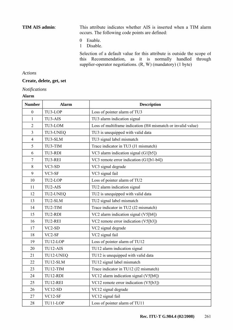
7.2 Fault management The ONT supports limited fault management only. Most of the operations are limited to failure indication. The OMCI supports failure reporting on many managed entities that are described throughout clause 9. An alarm table is defined for each of these entities.
To avoid erratic floods of alarm messages, it is common to filter, or soak, defects such as facility impairments before declaring them as alarms, and to soak defect clearing before retiring the alarm. The declaration soak time is typically 2.5±0.5 seconds, while the retirement soak time is typically 10.5±0.5 seconds. Which alarms are to be soaked, and what the soak intervals should be, are regarded as vendor-specific choices. Interoperability considerations, however, require that alarms be soaked at exactly one of the OLT or ONT, and this Recommendation specifies that they be soaked at the ONT.
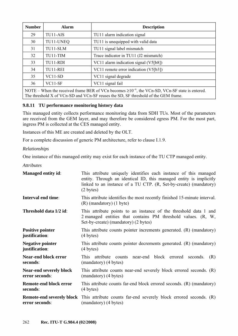
7.3 Performance management The ONT has only limited performance monitoring. The OMCI supports performance monitoring using a subset of managed entities that are described throughout clause 9. These managed entities can be identified by the words "performance monitoring history data" in their names.
Note that all performance monitoring related managed entities are created at the request of the OLT.
All history data shall be maintained in the OLT.
7.4 Security management [ITU-T G.984.3] specifies some mechanisms from the viewpoint of security. That includes the downstream data encryption of the ONT. The ONT2-G managed entity can enable/disable the downstream encryption function.
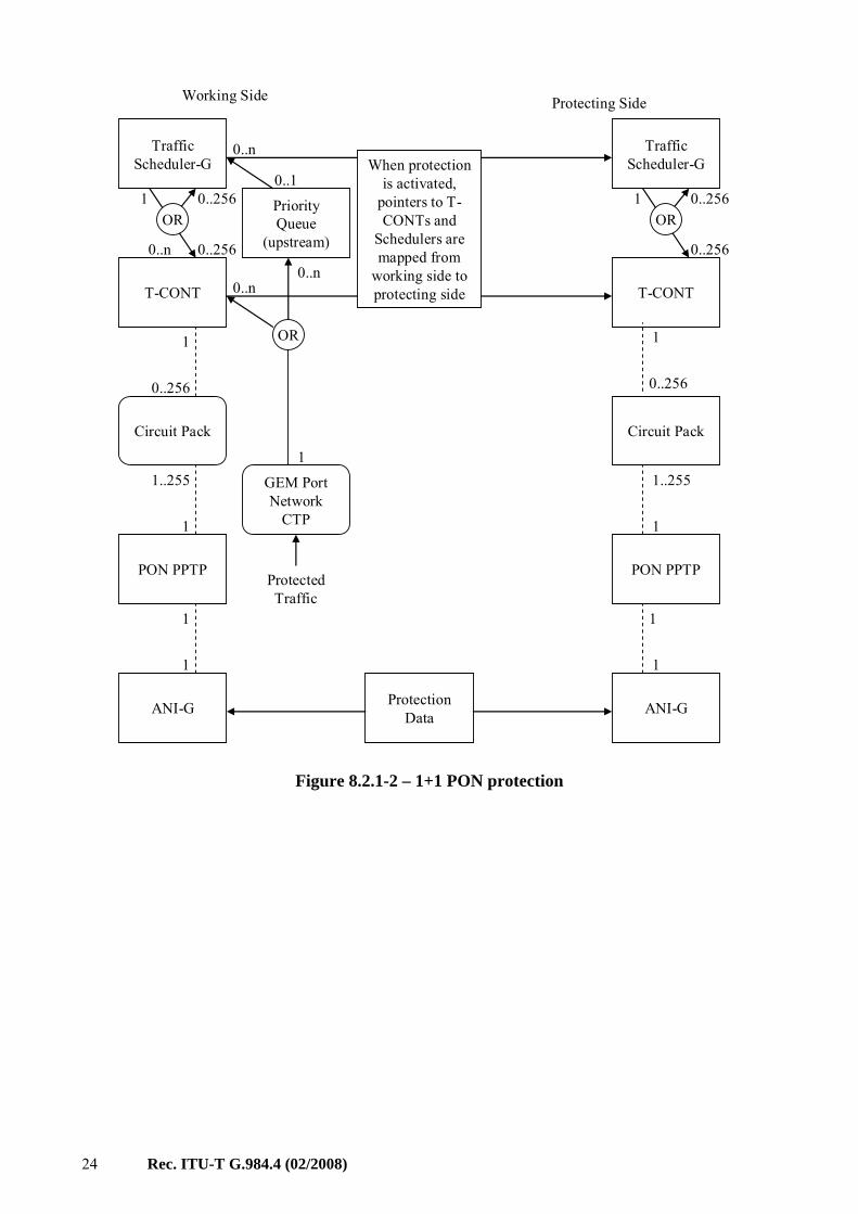
This Recommendation supports the protection function. The type C protection configuration that is defined in [b-ITU-T G.984.1] is considered in this Recommendation. As the switching behaviour for PON protection will be done in the TC layer, this Recommendation defines a managed entity to specify the protection capability.
8 Protocol-independent MIB for the OMCI The OMCI should be defined to allow vendors to offer modular, incremental capabilities to meet different levels of customer needs. This Recommendation defines a protocol necessary to support capabilities identified by [ITU-T G.984.2] and [ITU-T G.984.3]. It is important for interoperability, yet it allows for optional components and future extensions.
14 Rec. ITU-T G.984.4 (02/2008)
A protocol-independent MIB is used to describe the exchange of information across the OMCI. It forms the basis from which protocol-specific models are defined. This MIB has as much commonality as possible with the related generic MIB as defined in other ITU-T Recommendations. It is intended to make the OMCI relatively simple while maintaining consistency with the MIB used by the interface between the network-element manager and the OLT.
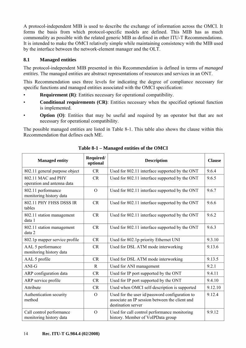
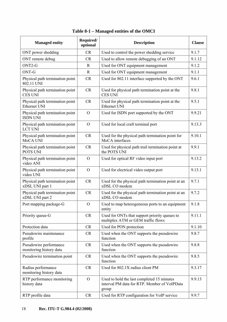
8.1 Managed entities The protocol-independent MIB presented in this Recommendation is defined in terms of managed entities. The managed entities are abstract representations of resources and services in an ONT.
This Recommendation uses three levels for indicating the degree of compliance necessary for specific functions and managed entities associated with the OMCI specification: • Requirement (R): Entities necessary for operational compatibility. • Conditional requirements (CR): Entities necessary when the specified optional function
is implemented. • Option (O): Entities that may be useful and required by an operator but that are not
necessary for operational compatibility.
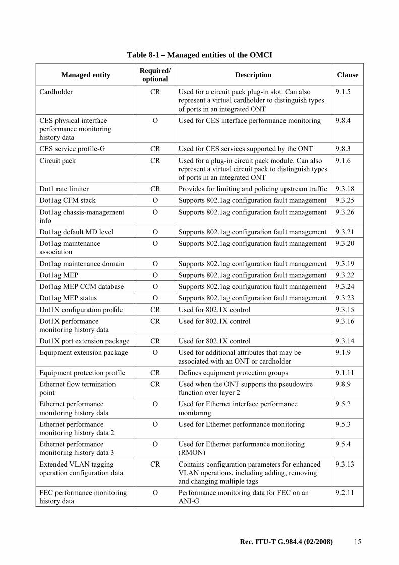
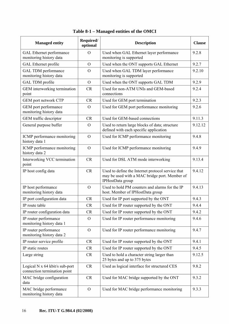
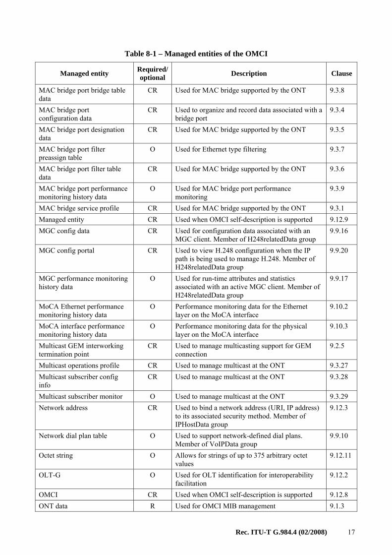
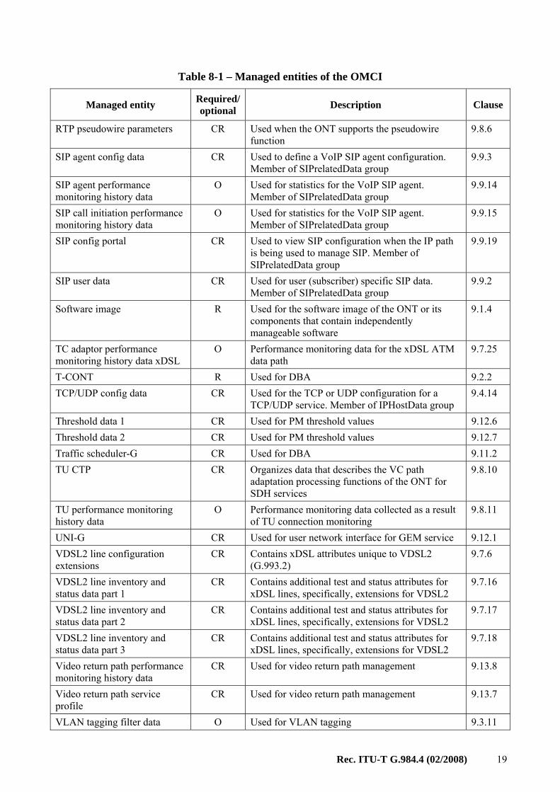
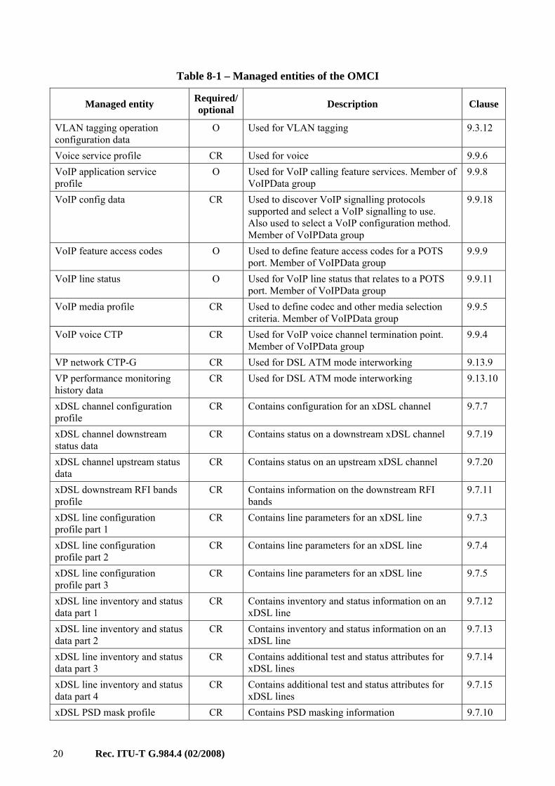
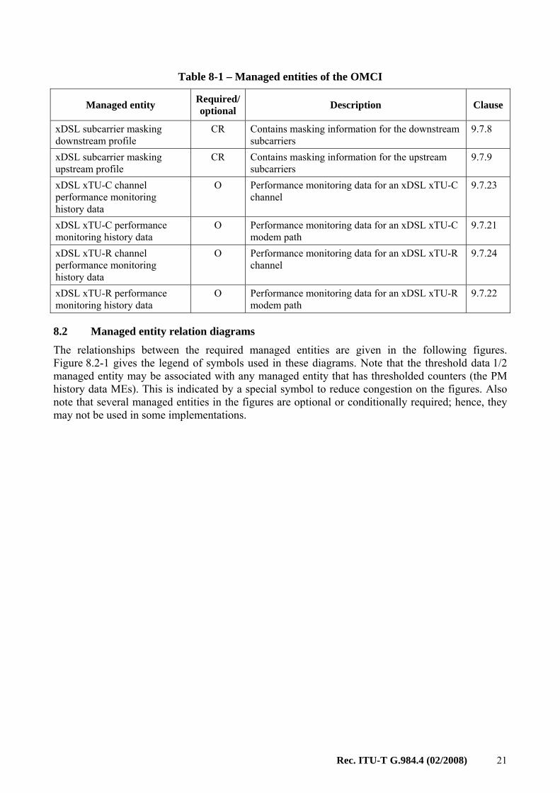
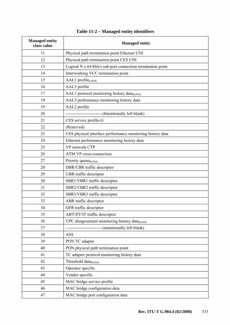
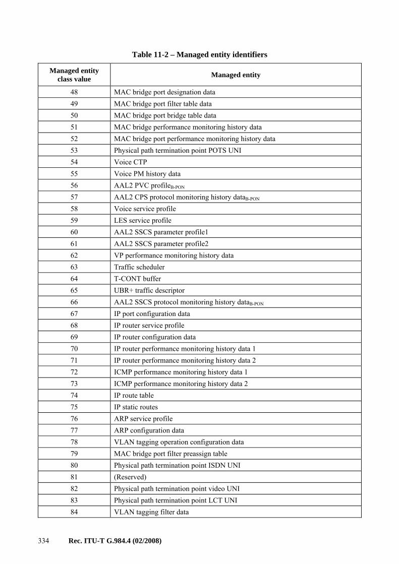
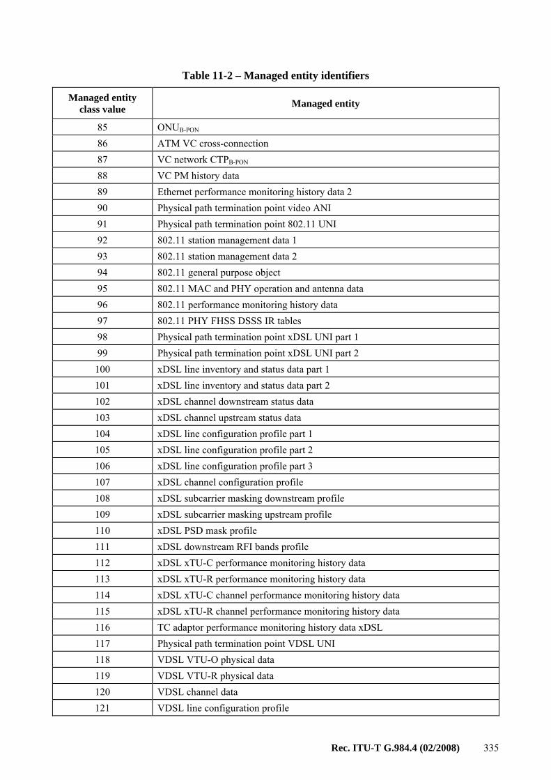
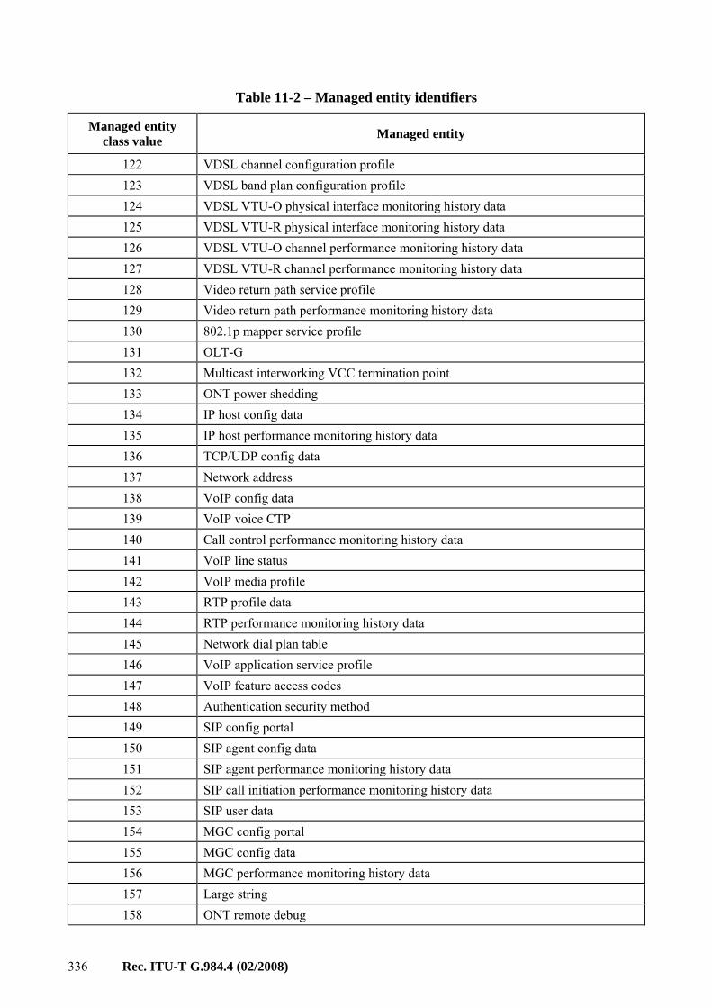
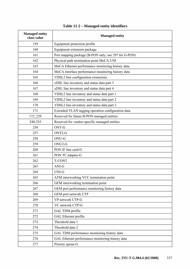
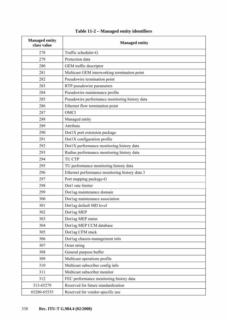
The possible managed entities are listed in Table 8-1. This table also shows the clause within this Recommendation that defines each ME.
802.11 general purpose object CR Used for 802.11 interface supported by the ONT 9.6.4 802.11 MAC and PHY operation and antenna data
CR Used for 802.11 interface supported by the ONT 9.6.5
802.11 performance monitoring history data
O Used for 802.11 interface supported by the ONT 9.6.7
802.11 PHY FHSS DSSS IR tables
CR Used for 802.11 interface supported by the ONT 9.6.6
802.11 station management data 1
CR Used for 802.11 interface supported by the ONT 9.6.2
802.11 station management data 2
CR Used for 802.11 interface supported by the ONT 9.6.3
802.1p mapper service profile CR Used for 802.1p priority Ethernet UNI 9.3.10 AAL 5 performance monitoring history data
CR Used for DSL ATM mode interworking 9.13.6
AAL 5 profile CR Used for DSL ATM mode interworking 9.13.5 ANI-G R Used for ANI management 9.2.1 ARP configuration data CR Used for IP port supported by the ONT 9.4.11 ARP service profile CR Used for IP port supported by the ONT 9.4.10 Attribute CR Used when OMCI self-description is supported 9.12.10 Authentication security method
O Used for the user id/password configuration to associate an IP session between the client and destination server
9.12.4
Call control performance monitoring history data
O Used for call control performance monitoring history. Member of VoIPData group
O Used when GAL Ethernet layer performance monitoring is supported
9.2.8
GAL Ethernet profile O Used when the ONT supports GAL Ethernet 9.2.7 GAL TDM performance monitoring history data
O Used when GAL TDM layer performance monitoring is supported
9.2.10
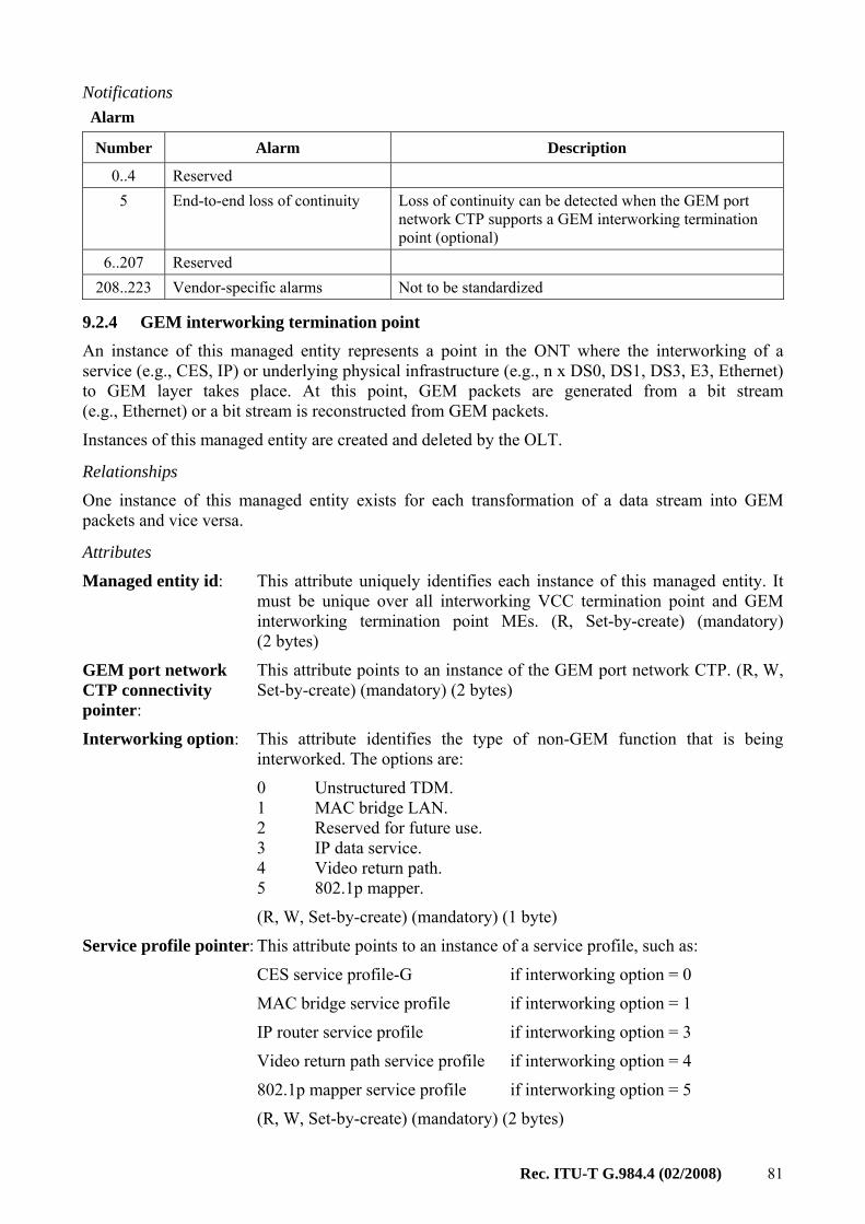
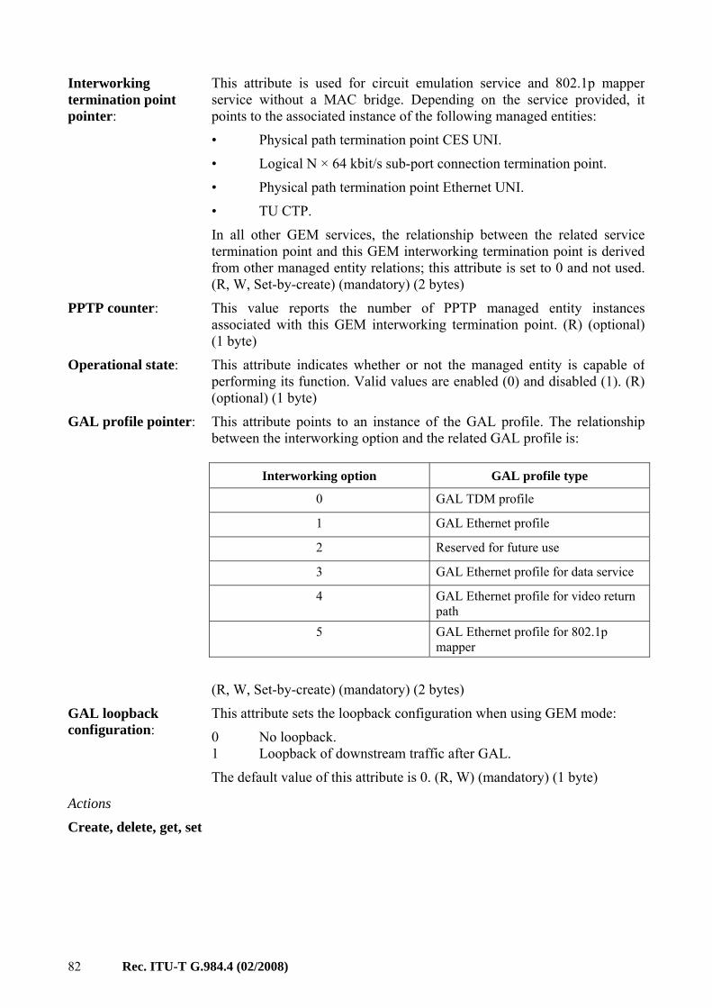
GAL TDM profile O Used when the ONT supports GAL TDM 9.2.9 GEM interworking termination point
CR Used for non-ATM UNIs and GEM-based connections
9.2.4
GEM port network CTP CR Used for GEM port termination 9.2.3 GEM port performance monitoring history data
O Used for GEM port performance monitoring 9.2.6
GEM traffic descriptor CR Used for GEM-based connections 9.11.3 General purpose buffer O Used to return large blocks of data; structure
defined with each specific application 9.12.12
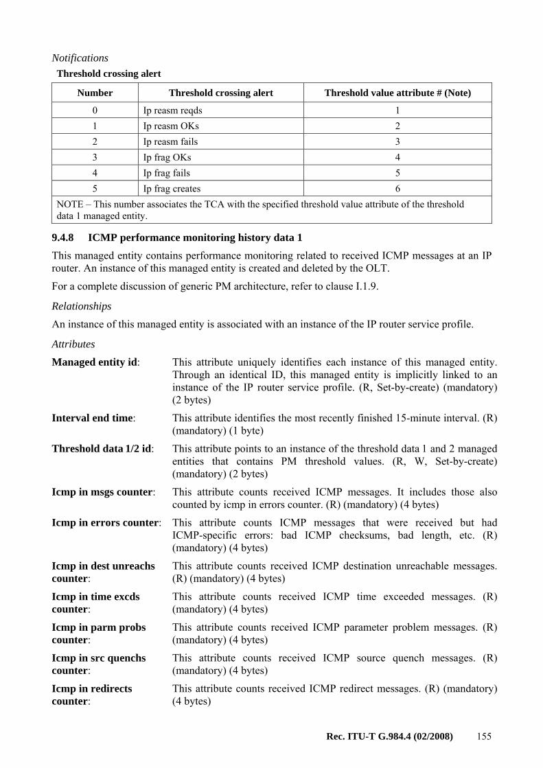
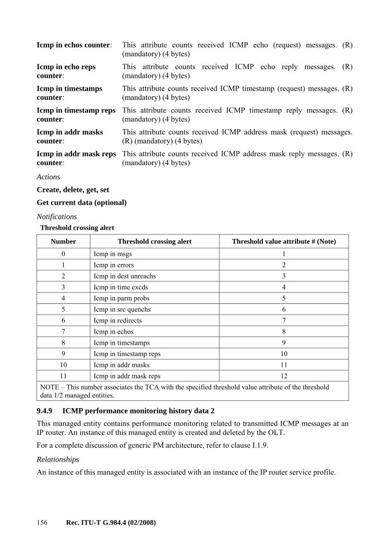
ICMP performance monitoring history data 1
O Used for ICMP performance monitoring 9.4.8
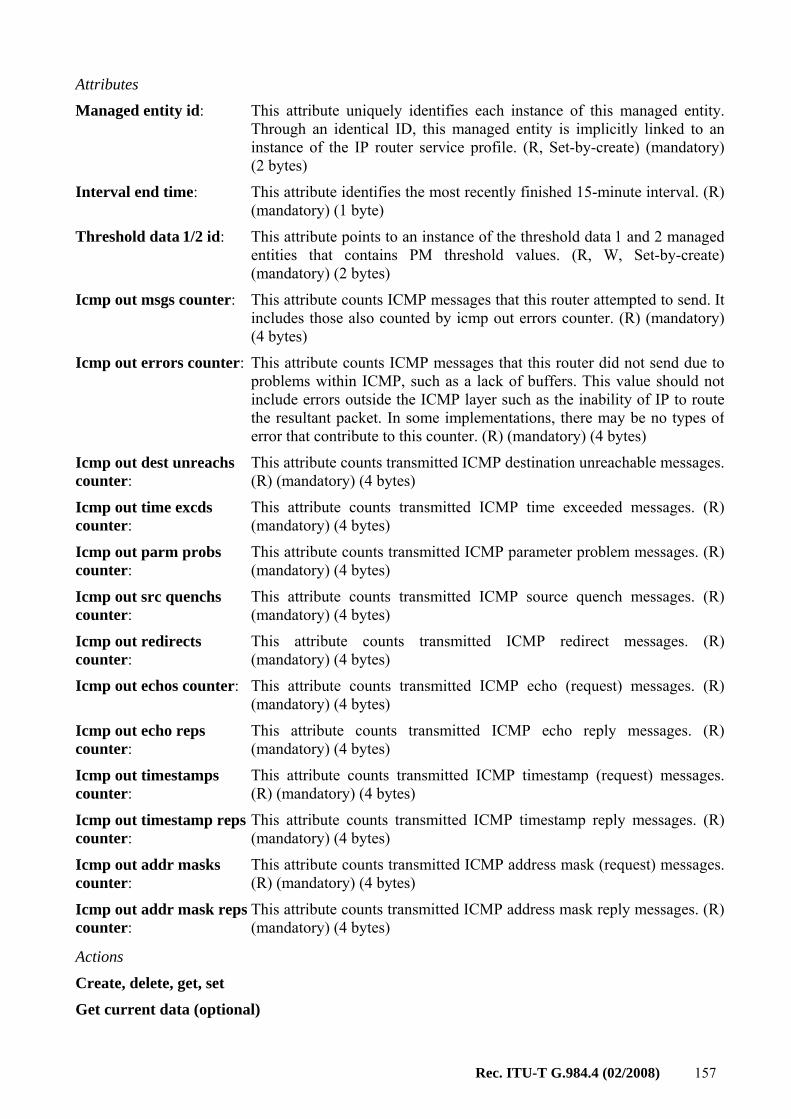
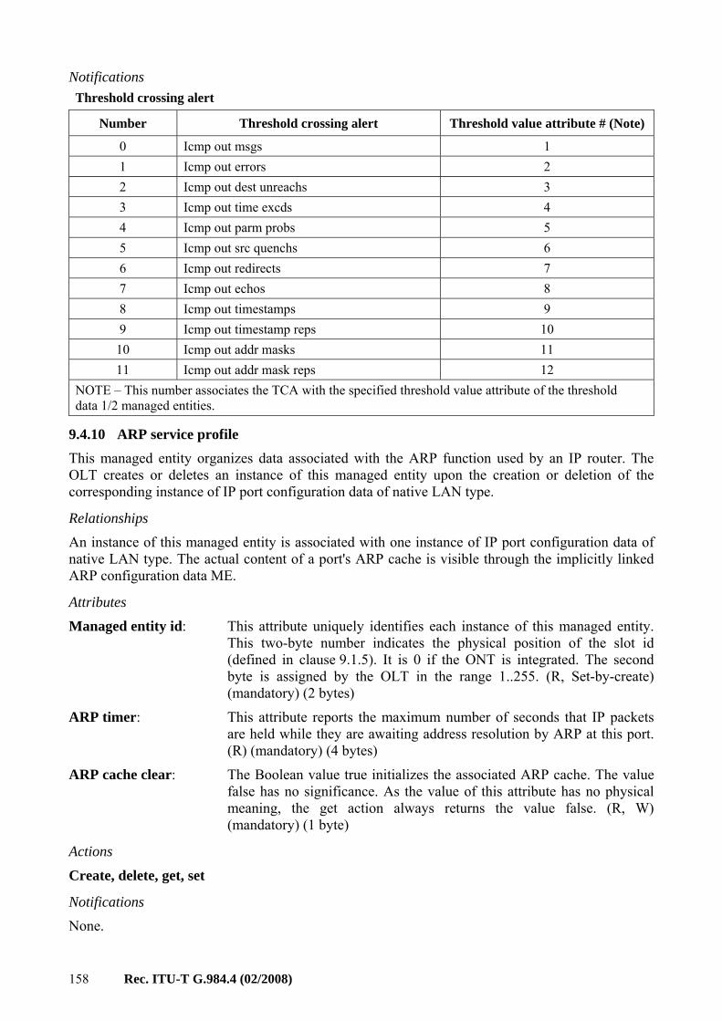
ICMP performance monitoring history data 2
O Used for ICMP performance monitoring 9.4.9
Interworking VCC termination point
CR Used for DSL ATM mode interworking 9.13.4
IP host config data CR Used to define the Internet protocol service that may be used with a MAC bridge port. Member of IPHostData group
9.4.12
IP host performance monitoring history data
O Used to hold PM counters and alarms for the IP host. Member of IPHostData group
9.4.13
IP port configuration data CR Used for IP port supported by the ONT 9.4.3 IP route table CR Used for IP router supported by the ONT 9.4.4 IP router configuration data CR Used for IP router supported by the ONT 9.4.2 IP router performance monitoring history data 1
O Used for IP router performance monitoring 9.4.6
IP router performance monitoring history data 2
O Used for IP router performance monitoring 9.4.7
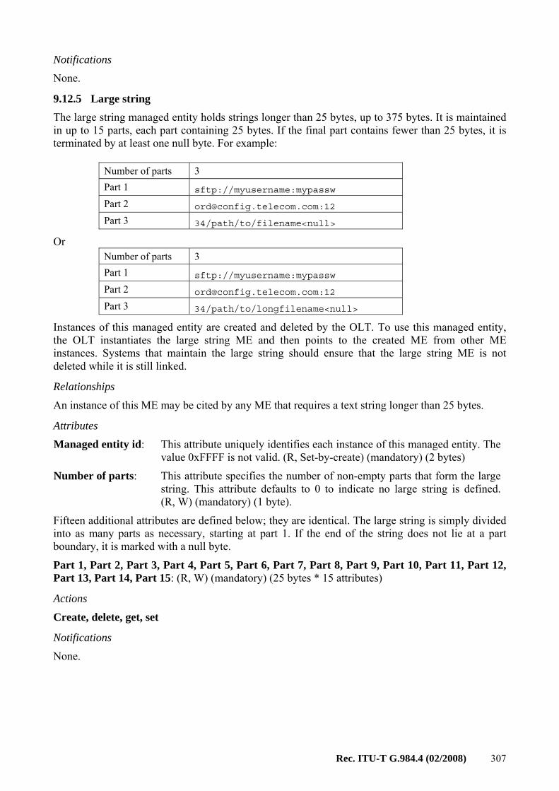
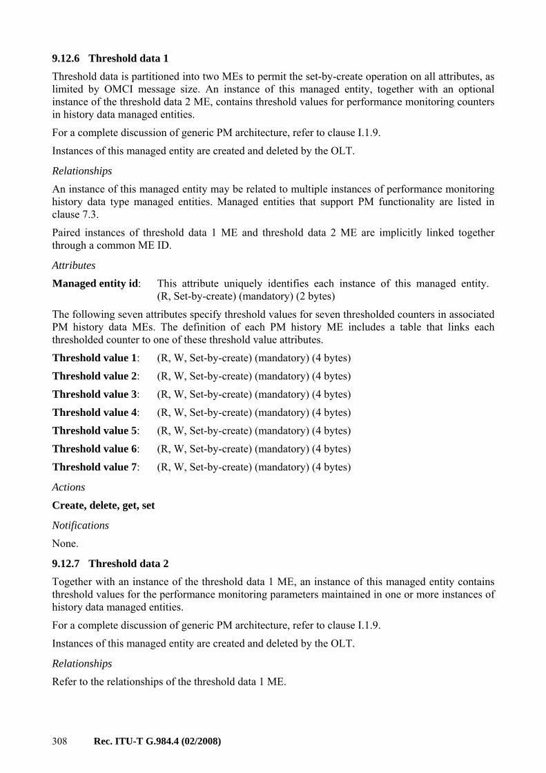
IP router service profile CR Used for IP router supported by the ONT 9.4.1 IP static routes CR Used for IP router supported by the ONT 9.4.5 Large string CR Used to hold a character string larger than
25 bytes and up to 375 bytes 9.12.5
Logical N x 64 kbit/s sub-port connection termination point
CR Used as logical interface for structured CES 9.8.2
MAC bridge configuration data
CR Used for MAC bridge supported by the ONT 9.3.2
MAC bridge performance monitoring history data
O Used for MAC bridge performance monitoring 9.3.3
CR Used to organize and record data associated with a bridge port
9.3.4
MAC bridge port designation data
CR Used for MAC bridge supported by the ONT 9.3.5
MAC bridge port filter preassign table
O Used for Ethernet type filtering 9.3.7
MAC bridge port filter table data
CR Used for MAC bridge supported by the ONT 9.3.6
MAC bridge port performance monitoring history data
O Used for MAC bridge port performance monitoring
9.3.9
MAC bridge service profile CR Used for MAC bridge supported by the ONT 9.3.1 Managed entity CR Used when OMCI self-description is supported 9.12.9 MGC config data CR Used for configuration data associated with an
MGC client. Member of H248relatedData group 9.9.16
MGC config portal CR Used to view H.248 configuration when the IP path is being used to manage H.248. Member of H248relatedData group
9.9.20
MGC performance monitoring history data
O Used for run-time attributes and statistics associated with an active MGC client. Member of H248relatedData group
9.9.17
MoCA Ethernet performance monitoring history data
O Performance monitoring data for the Ethernet layer on the MoCA interface
9.10.2
MoCA interface performance monitoring history data
O Performance monitoring data for the physical layer on the MoCA interface
9.10.3
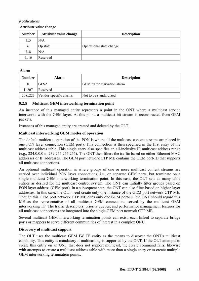
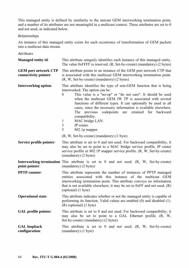
Multicast GEM interworking termination point
CR Used to manage multicasting support for GEM connection
9.2.5
Multicast operations profile CR Used to manage multicast at the ONT 9.3.27 Multicast subscriber config info
CR Used to manage multicast at the ONT 9.3.28
Multicast subscriber monitor O Used to manage multicast at the ONT 9.3.29 Network address CR Used to bind a network address (URI, IP address)
to its associated security method. Member of IPHostData group
9.12.3
Network dial plan table O Used to support network-defined dial plans. Member of VoIPData group
9.9.10
Octet string O Allows for strings of up to 375 arbitrary octet values
9.12.11
OLT-G O Used for OLT identification for interoperability facilitation
9.12.2
OMCI CR Used when OMCI self-description is supported 9.12.8 ONT data R Used for OMCI MIB management 9.1.3
ONT power shedding CR Used to control the power shedding service 9.1.7 ONT remote debug CR Used to allow remote debugging of an ONT 9.1.12 ONT2-G R Used for ONT equipment management 9.1.2 ONT-G R Used for ONT equipment management 9.1.1 Physical path termination point 802.11 UNI
CR Used for 802.11 interface supported by the ONT 9.6.1
Physical path termination point CES UNI
CR Used for physical path termination point at the CES UNI
9.8.1
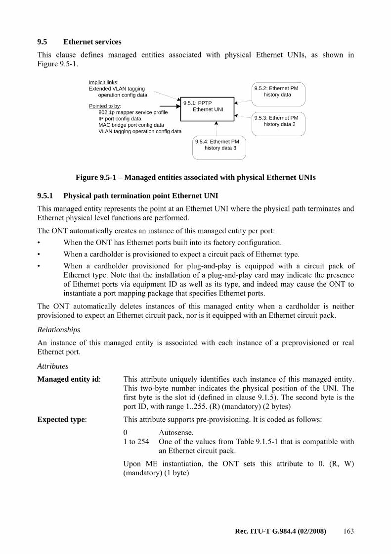
Physical path termination point Ethernet UNI
CR Used for physical path termination point at the Ethernet UNI
9.5.1
Physical path termination point ISDN UNI
O Used for ISDN port supported by the ONT 9.9.21
Physical path termination point LCT UNI
O Used for local craft terminal port 9.13.3
Physical path termination point MoCA UNI
CR Used for the physical path termination point for MoCA interfaces
9.10.1
Physical path termination point POTS UNI
CR Used for physical path trail termination point at the POTS UNI
9.9.1
Physical path termination point video ANI
O Used for optical RF video input port 9.13.2
Physical path termination point video UNI
O Used for electrical video output port 9.13.1
Physical path termination point xDSL UNI part 1
CR Used for the physical path termination point at an xDSL CO modem
9.7.1
Physical path termination point xDSL UNI part 2
CR Used for the physical path termination point at an xDSL CO modem
9.7.2
Port mapping package-G O Used to map heterogeneous ports to an equipment entity
9.1.8
Priority queue-G CR Used for ONTs that support priority queues to multiplex ATM or GEM traffic flows
9.11.1
Protection data CR Used for PON protection 9.1.10 Pseudowire maintenance profile
CR Used when the ONT supports the pseudowire function
9.8.7
Pseudowire performance monitoring history data
CR Used when the ONT supports the pseudowire function
9.8.8
Pseudowire termination point CR Used when the ONT supports the pseudowire function
9.8.5
Radius performance monitoring history data
CR Used for 802.1X radius client PM 9.3.17
RTP performance monitoring history data
O Used to hold the last completed 15 minutes interval PM data for RTP. Member of VoIPData group
9.9.13
RTP profile data CR Used for RTP configuration for VoIP service 9.9.7
RTP pseudowire parameters CR Used when the ONT supports the pseudowire function
9.8.6
SIP agent config data CR Used to define a VoIP SIP agent configuration. Member of SIPrelatedData group
9.9.3
SIP agent performance monitoring history data
O Used for statistics for the VoIP SIP agent. Member of SIPrelatedData group
9.9.14
SIP call initiation performance monitoring history data
O Used for statistics for the VoIP SIP agent. Member of SIPrelatedData group
9.9.15
SIP config portal CR Used to view SIP configuration when the IP path is being used to manage SIP. Member of SIPrelatedData group
9.9.19
SIP user data CR Used for user (subscriber) specific SIP data. Member of SIPrelatedData group
9.9.2
Software image R Used for the software image of the ONT or its components that contain independently manageable software
9.1.4
TC adaptor performance monitoring history data xDSL
O Performance monitoring data for the xDSL ATM data path
9.7.25
T-CONT R Used for DBA 9.2.2 TCP/UDP config data CR Used for the TCP or UDP configuration for a
TCP/UDP service. Member of IPHostData group 9.4.14
Threshold data 1 CR Used for PM threshold values 9.12.6 Threshold data 2 CR Used for PM threshold values 9.12.7 Traffic scheduler-G CR Used for DBA 9.11.2 TU CTP CR Organizes data that describes the VC path
adaptation processing functions of the ONT for SDH services
9.8.10
TU performance monitoring history data
O Performance monitoring data collected as a result of TU connection monitoring
9.8.11
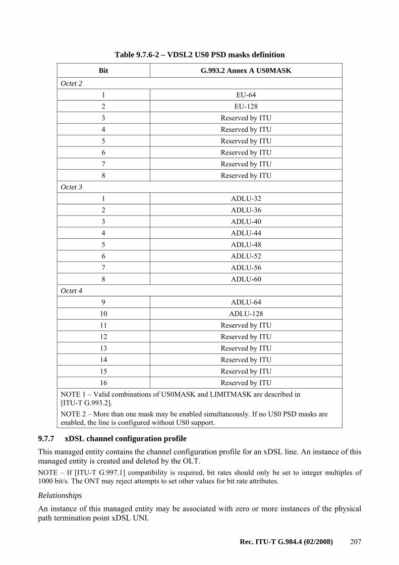
UNI-G CR Used for user network interface for GEM service 9.12.1 VDSL2 line configuration extensions
CR Contains xDSL attributes unique to VDSL2 (G.993.2)
9.7.6
VDSL2 line inventory and status data part 1
CR Contains additional test and status attributes for xDSL lines, specifically, extensions for VDSL2
9.7.16
VDSL2 line inventory and status data part 2
CR Contains additional test and status attributes for xDSL lines, specifically, extensions for VDSL2
9.7.17
VDSL2 line inventory and status data part 3
CR Contains additional test and status attributes for xDSL lines, specifically, extensions for VDSL2
9.7.18
Video return path performance monitoring history data
CR Used for video return path management 9.13.8
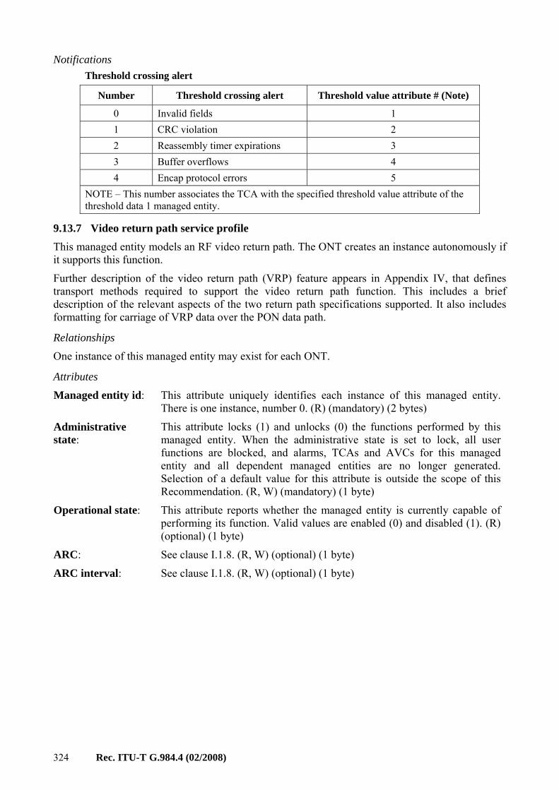
Video return path service profile
CR Used for video return path management 9.13.7
VLAN tagging filter data O Used for VLAN tagging 9.3.11
Voice service profile CR Used for voice 9.9.6 VoIP application service profile
O Used for VoIP calling feature services. Member of VoIPData group
9.9.8
VoIP config data CR Used to discover VoIP signalling protocols supported and select a VoIP signalling to use. Also used to select a VoIP configuration method. Member of VoIPData group
9.9.18
VoIP feature access codes O Used to define feature access codes for a POTS port. Member of VoIPData group
9.9.9
VoIP line status O Used for VoIP line status that relates to a POTS port. Member of VoIPData group
9.9.11
VoIP media profile CR Used to define codec and other media selection criteria. Member of VoIPData group
9.9.5
VoIP voice CTP CR Used for VoIP voice channel termination point. Member of VoIPData group
9.9.4
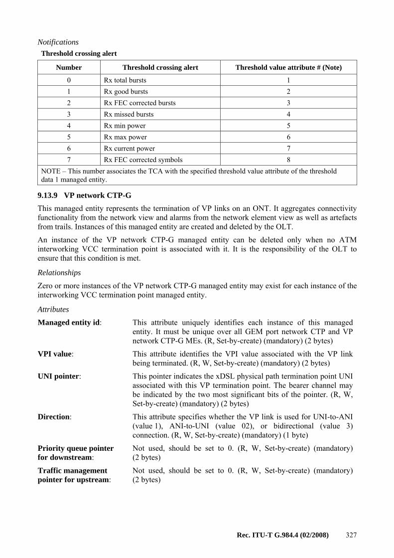
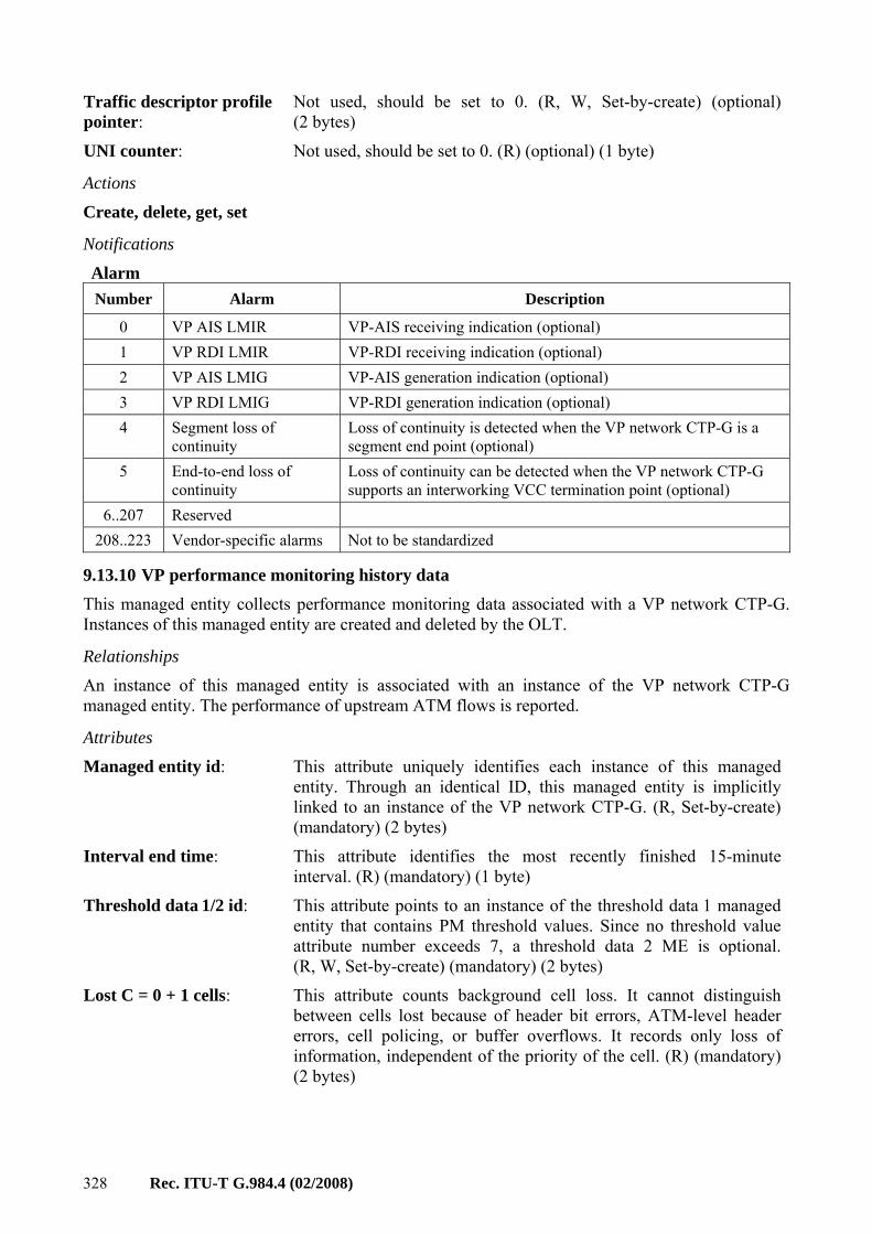
VP network CTP-G CR Used for DSL ATM mode interworking 9.13.9 VP performance monitoring history data
CR Used for DSL ATM mode interworking 9.13.10
xDSL channel configuration profile
CR Contains configuration for an xDSL channel 9.7.7
xDSL channel downstream status data
CR Contains status on a downstream xDSL channel 9.7.19
xDSL channel upstream status data
CR Contains status on an upstream xDSL channel 9.7.20
xDSL downstream RFI bands profile
CR Contains information on the downstream RFI bands
9.7.11
xDSL line configuration profile part 1
CR Contains line parameters for an xDSL line 9.7.3
xDSL line configuration profile part 2
CR Contains line parameters for an xDSL line 9.7.4
xDSL line configuration profile part 3
CR Contains line parameters for an xDSL line 9.7.5
xDSL line inventory and status data part 1
CR Contains inventory and status information on an xDSL line
9.7.12
xDSL line inventory and status data part 2
CR Contains inventory and status information on an xDSL line
9.7.13
xDSL line inventory and status data part 3
CR Contains additional test and status attributes for xDSL lines
9.7.14
xDSL line inventory and status data part 4
CR Contains additional test and status attributes for xDSL lines
9.7.15
xDSL PSD mask profile CR Contains PSD masking information 9.7.10
CR Contains masking information for the downstream subcarriers
9.7.8
xDSL subcarrier masking upstream profile
CR Contains masking information for the upstream subcarriers
9.7.9
xDSL xTU-C channel performance monitoring history data
O Performance monitoring data for an xDSL xTU-C channel
9.7.23
xDSL xTU-C performance monitoring history data
O Performance monitoring data for an xDSL xTU-C modem path
9.7.21
xDSL xTU-R channel performance monitoring history data
O Performance monitoring data for an xDSL xTU-R channel
9.7.24
xDSL xTU-R performance monitoring history data
O Performance monitoring data for an xDSL xTU-R modem path
9.7.22
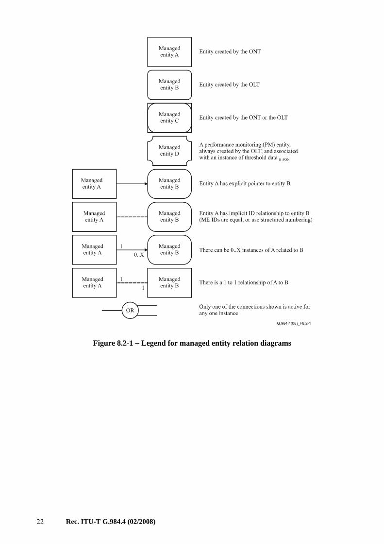
8.2 Managed entity relation diagrams The relationships between the required managed entities are given in the following figures. Figure 8.2-1 gives the legend of symbols used in these diagrams. Note that the threshold data 1/2 managed entity may be associated with any managed entity that has thresholded counters (the PM history data MEs). This is indicated by a special symbol to reduce congestion on the figures. Also note that several managed entities in the figures are optional or conditionally required; hence, they may not be used in some implementations.
22 Rec. ITU-T G.984.4 (02/2008)
Figure 8.2-1 − Legend for managed entity relation diagrams
Rec. ITU-T G.984.4 (02/2008) 23
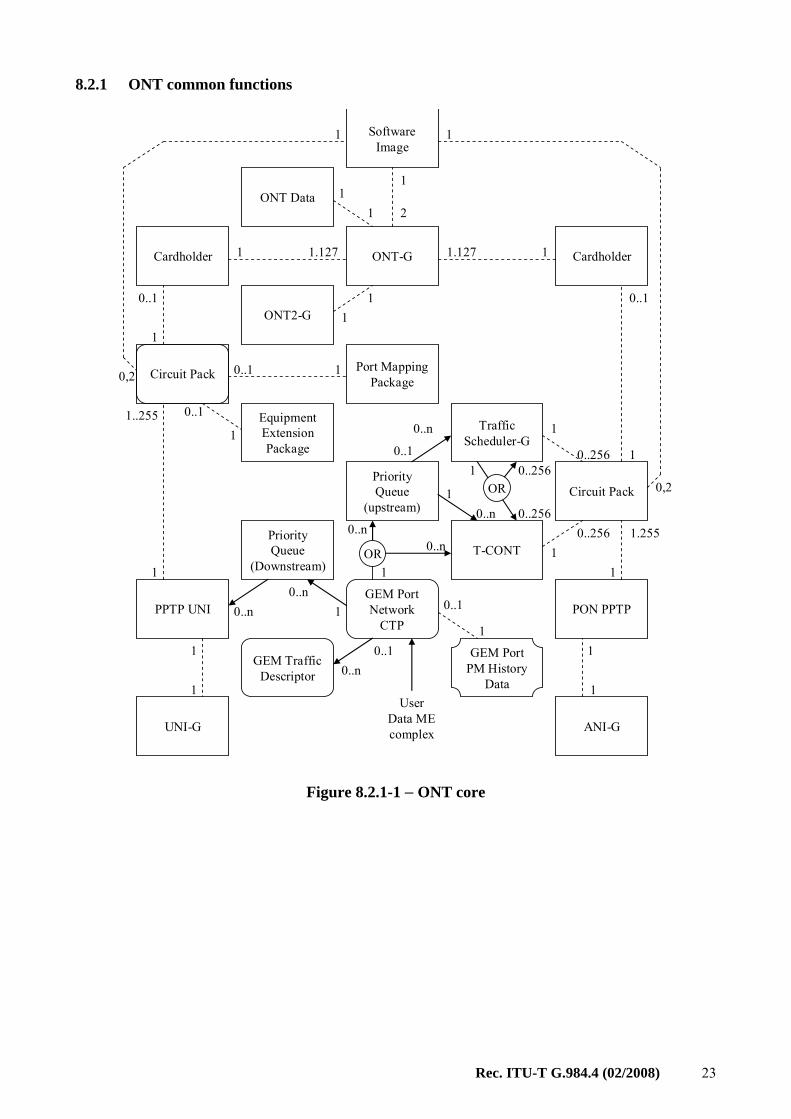
8.2.1 ONT common functions
ONT-G
Circuit Pack
ANI-G
Cardholder Cardholder
ONT Data
Software Image
PON PPTP PPTP UNI
UNI-G
1
1
1
1..255
1
0..1
1 1.127 1.127 1
11
1.255
1
1
0..1
1
1
T-CONT0..256
1
1
2
0,2
0,2
1
Circuit Pack
0..256
Priority Queue
(Downstream)
Priority Queue
(upstream)
Traffic Scheduler-G
10..n
0..1
1
0..n
OR
GEM Port Network
CTP
10..n
1
0..256
0..256
OR
0..n
0..n0..n
1
1
ONT2-G 11
1
0..1
GEM Traffic Descriptor 0..n
0..1 GEM Port PM History
Data
Port Mapping Package
Equipment Extension Package
1
10..1
0..1
User Data ME complex
Figure 8.2.1-1 − ONT core
24 Rec. ITU-T G.984.4 (02/2008)
ANI-G
PON PPTP
1
1
1
T-CONT
0..256
Traffic Scheduler-G
OR
GEM Port Network
CTP
1
0..256
0..256
Protection DataANI-G
PON PPTP
1
1
1
T-CONT
0..256
Traffic Scheduler-G
OR
0..n
1
0..256
0..256 Priority Queue
(upstream)
0..1
OR
0..n0..n
1
0..n
Circuit PackCircuit Pack
1
1..255
1
1..255
Working Side Protecting Side
When protection is activated,
pointers to T-CONTs and
Schedulers are mapped from
working side to protecting side
ProtectedTraffic
Figure 8.2.1-2 – 1+1 PON protection
Rec. ITU-T G.984.4 (02/2008) 25
ANI-G
PON PPTP
1
1
1
T-CONT
0..256
Traffic Scheduler-G
OR
GEM Port Network
CTP
1
0..256
0..256
Protection DataANI-G
PON PPTP
1
1
1
T-CONT
0..256
Traffic Scheduler-G
OR
0..n
1
0..256
0..256 Priority Queue
(upstream)
0..1
OR
0..n0..n
1
0..n
Circuit PackCircuit Pack
1
1..255
1
1..255
Working Side Protecting Side
When protection is activated,
pointers to T-CONTs and
Schedulers are mapped from
working side to protecting side
0..1
OR
0..n
1
GEM Port Network
CTP
Priority Queue
(upstream)
0..n
ProtectedTraffic
ExtraTraffic
0..n
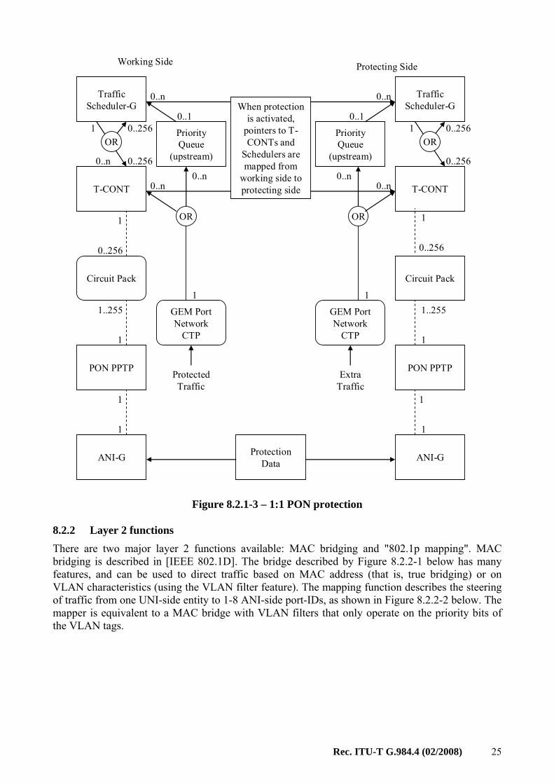
Figure 8.2.1-3 – 1:1 PON protection
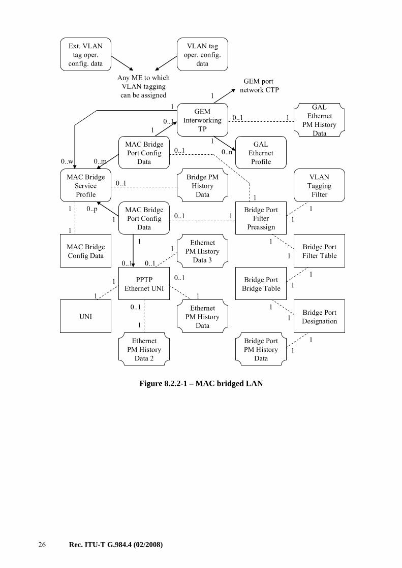
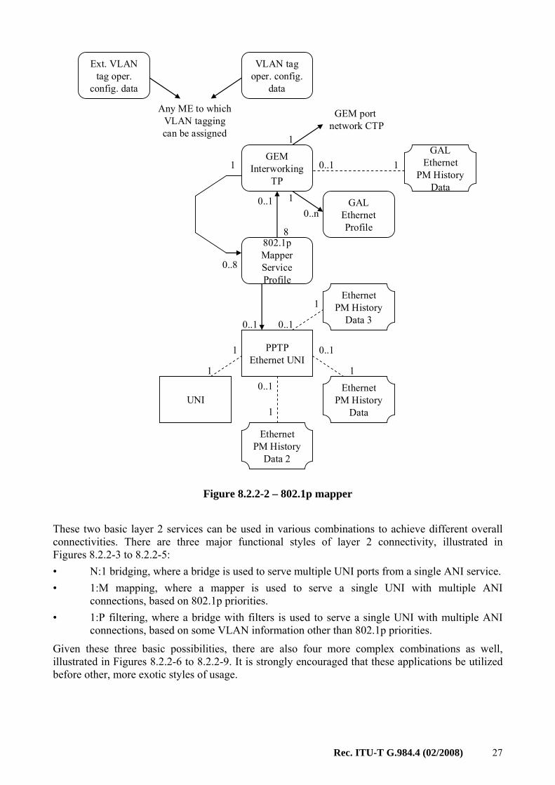
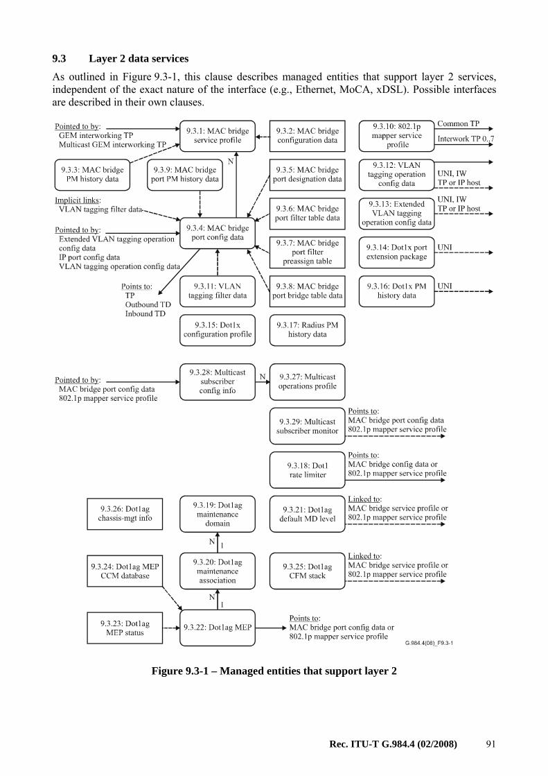
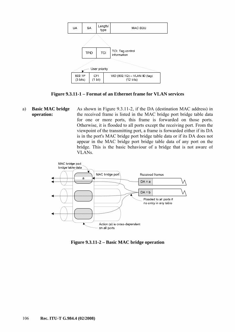
8.2.2 Layer 2 functions There are two major layer 2 functions available: MAC bridging and "802.1p mapping". MAC bridging is described in [IEEE 802.1D]. The bridge described by Figure 8.2.2-1 below has many features, and can be used to direct traffic based on MAC address (that is, true bridging) or on VLAN characteristics (using the VLAN filter feature). The mapping function describes the steering of traffic from one UNI-side entity to 1-8 ANI-side port-IDs, as shown in Figure 8.2.2-2 below. The mapper is equivalent to a MAC bridge with VLAN filters that only operate on the priority bits of the VLAN tags.
26 Rec. ITU-T G.984.4 (02/2008)
GEM Interworking
TP
0..p1
MAC Bridge Port Config
Data
MAC Bridge Service Profile
MAC Bridge Port Config
Data
MAC Bridge Config Data
11
1PPTP
Ethernet UNI
0..1
UNI
1
1
1
Bridge Port Designation
Bridge Port Filter Table
Bridge Port Bridge Table
VLAN Tagging
Filter
Bridge Port Filter
Preassign
1
0..11
1
GEM port network CTP
0..n
0..1
1
1
11
0..1
0..1
1
1
0..w 0..m
11
1
0..1 1
GAL Ethernet Profile
0..1 1
11
VLAN tag oper. config.
data
Ext. VLAN tag oper.
config. data
Any ME to which VLAN tagging can be assigned
0..11
1
Bridge PM History
Data
GAL Ethernet
PM History Data
Bridge Port PM History
Data
Ethernet PM History
Data 2
Ethernet PM History
Data
Ethernet PM History
Data 30..1
1
Figure 8.2.2-1 – MAC bridged LAN
Rec. ITU-T G.984.4 (02/2008) 27
GEM Interworking
TP
802.1p MapperService Profile
8
PPTP Ethernet UNI
UNI
1
1
0..1
1
0..1
0..8
0..1
0..1
1
1
1
1
GEM port network CTP
0..nGAL
Ethernet Profile
0..1 1
VLAN tag oper. config.
data
Ext. VLAN tag oper.
config. data
Any ME to which VLAN tagging can be assigned
GAL Ethernet
PM History Data
Ethernet PM History
Data
Ethernet PM History
Data 2
Ethernet PM History
Data 30..1
1
Figure 8.2.2-2 – 802.1p mapper
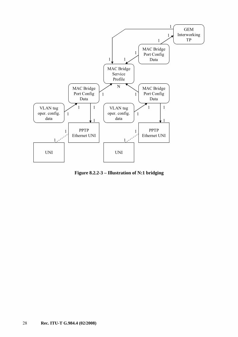
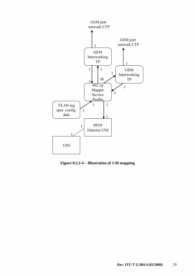
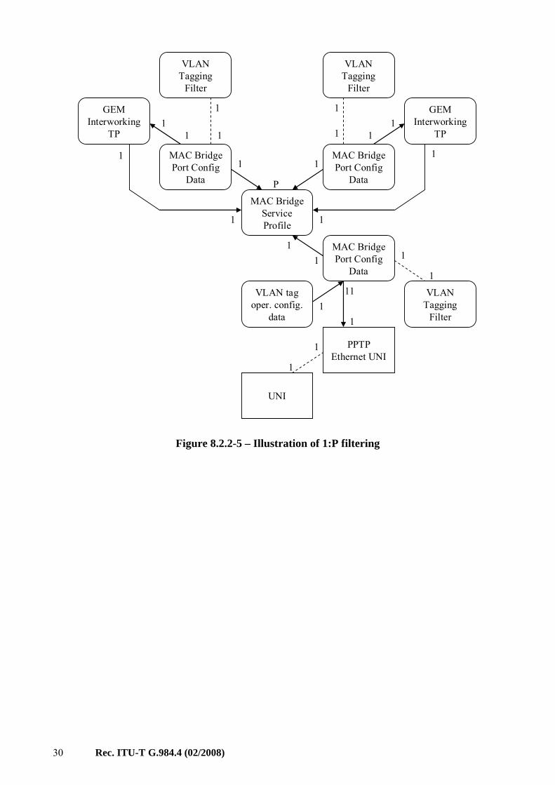
These two basic layer 2 services can be used in various combinations to achieve different overall connectivities. There are three major functional styles of layer 2 connectivity, illustrated in Figures 8.2.2-3 to 8.2.2-5: • N:1 bridging, where a bridge is used to serve multiple UNI ports from a single ANI service. • 1:M mapping, where a mapper is used to serve a single UNI with multiple ANI
connections, based on 802.1p priorities. • 1:P filtering, where a bridge with filters is used to serve a single UNI with multiple ANI
connections, based on some VLAN information other than 802.1p priorities.
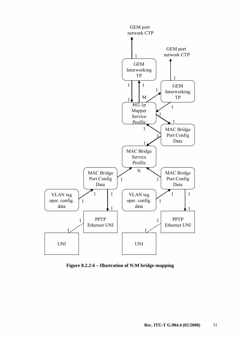
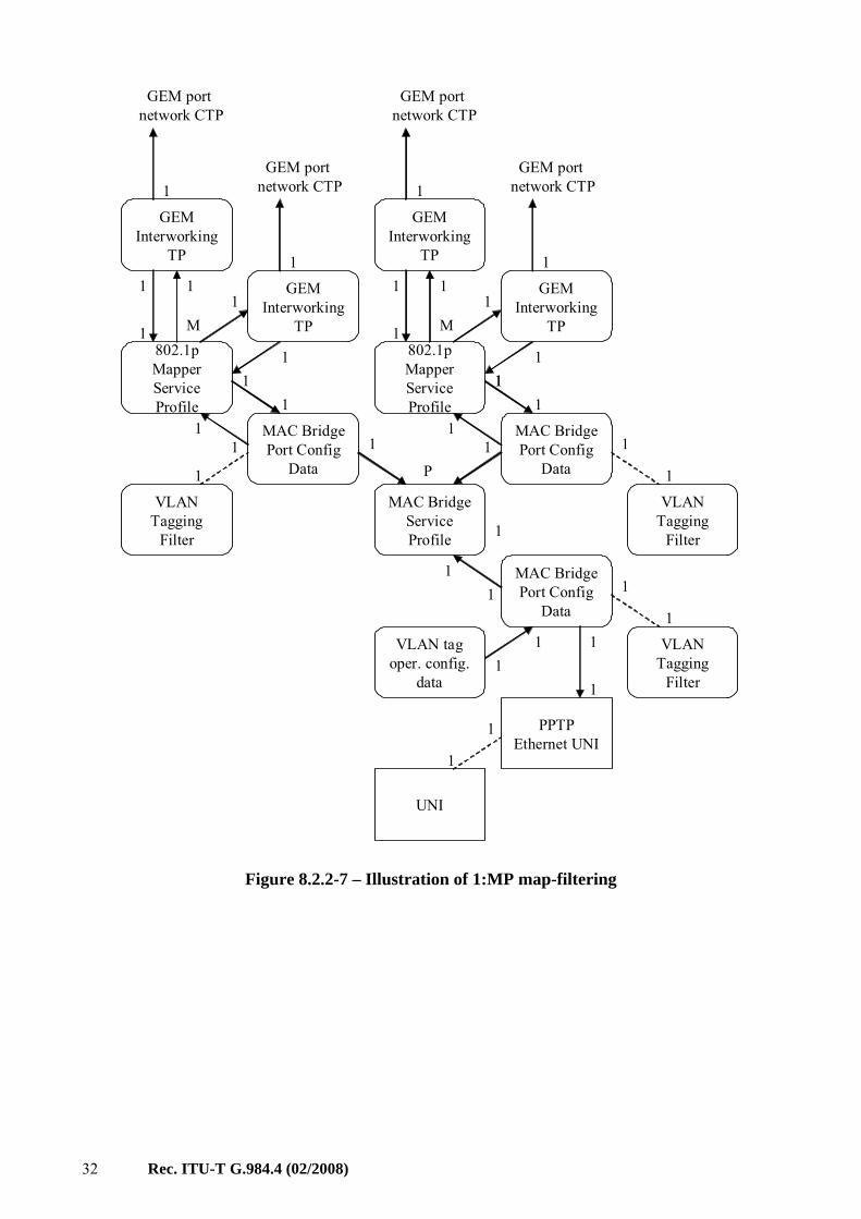
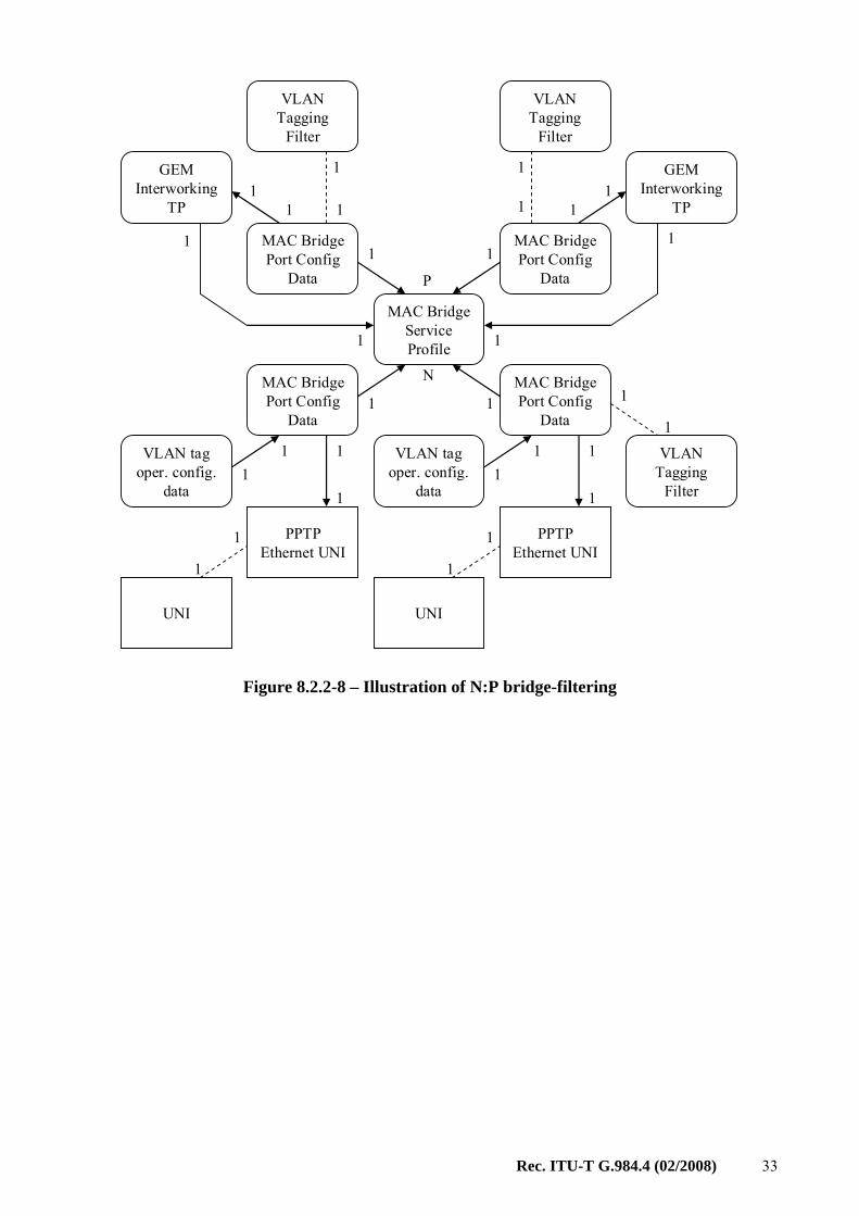
Given these three basic possibilities, there are also four more complex combinations as well, illustrated in Figures 8.2.2-6 to 8.2.2-9. It is strongly encouraged that these applications be utilized before other, more exotic styles of usage.
28 Rec. ITU-T G.984.4 (02/2008)
GEM Interworking
TP
N
MAC Bridge Port Config
Data
MAC Bridge Service Profile
MAC Bridge Port Config
Data
1
PPTP Ethernet UNI
1
UNI
1
1
1
1 1
11
1
1
MAC Bridge Port Config
Data
1
PPTP Ethernet UNI
1
UNI
1
1
1
VLAN tag oper. config.
data
VLAN tag oper. config.
data
11
11
Figure 8.2.2-3 – Illustration of N:1 bridging
Rec. ITU-T G.984.4 (02/2008) 29
802.1p MapperService Profile
PPTP Ethernet UNI
UNI
1
1
1
VLAN tag oper. config.
data
11
1
GEM Interworking
TP
1
GEM port network CTP
GEM Interworking
TP
1
GEM port network CTP
1
M
1
11
1
11
Figure 8.2.2-4 – Illustration of 1:M mapping
30 Rec. ITU-T G.984.4 (02/2008)
GEM Interworking
TP
MAC Bridge Port Config
Data
MAC Bridge Service Profile
MAC Bridge Port Config
Data
1
PPTP Ethernet UNI
1
UNI
1
1
1
1
11
11
1
VLAN Tagging
Filter
1
1
GEM Interworking
TP
MAC Bridge Port Config
Data
11
1
VLAN Tagging
Filter
1
1
1
VLAN Tagging
Filter
1
1
1
P
VLAN tag oper. config.
data
11
Figure 8.2.2-5 – Illustration of 1:P filtering
Rec. ITU-T G.984.4 (02/2008) 31
N
MAC Bridge Port Config
Data
MAC Bridge Service Profile
MAC Bridge Port Config
Data
1
PPTP Ethernet UNI
1
UNI
1
1
1
1
MAC Bridge Port Config
Data
1
PPTP Ethernet UNI
1
UNI
1
1
1
GEM Interworking
TP
1
GEM port network CTP
GEM Interworking
TP
1
GEM port network CTP
1
802.1p MapperService Profile
M
1
11
1
1
11
1
VLAN tag oper. config.
data
VLAN tag oper. config.
data
11
11
Figure 8.2.2-6 – Illustration of N:M bridge-mapping
32 Rec. ITU-T G.984.4 (02/2008)
MAC Bridge Port Config
Data
MAC Bridge Service Profile
MAC Bridge Port Config
Data
1
PPTP Ethernet UNI
1
UNI
1
1
1
1
1
1
VLAN Tagging
Filter
MAC Bridge Port Config
Data
VLAN Tagging
Filter
VLAN Tagging
Filter
1
1
1 1
11
GEM Interworking
TP
1
GEM port network CTP
GEM Interworking
TP
1
GEM port network CTP
1
802.1p MapperService Profile
M
1
11
1
1
GEM Interworking
TP
1
GEM port network CTP
GEM Interworking
TP
1
GEM port network CTP
1
802.1p MapperService Profile
M
1
11
1
111
P
11
11
VLAN tag oper. config.
data
11
Figure 8.2.2-7 – Illustration of 1:MP map-filtering
Rec. ITU-T G.984.4 (02/2008) 33
GEM Interworking
TP
MAC Bridge Port Config
Data
MAC Bridge Service Profile
MAC Bridge Port Config
Data
1
PPTP Ethernet UNI
1
UNI
1
1
1
1
11
11
VLAN Tagging
Filter
1
1
GEM Interworking
TP
MAC Bridge Port Config
Data
11
11
VLAN Tagging
Filter
1
1
1
VLAN Tagging
Filter
1
1
NMAC Bridge Port Config
Data
1
PPTP Ethernet UNI
1
UNI
1
1
1
P
VLAN tag oper. config.
data
VLAN tag oper. config.
data
11
11
Figure 8.2.2-8 – Illustration of N:P bridge-filtering
34 Rec. ITU-T G.984.4 (02/2008)
N
MAC Bridge Port Config
Data
MAC Bridge Service Profile
MAC Bridge Port Config
Data
1
PPTP Ethernet UNI
1
UNI
1
1
1MAC Bridge Port Config
Data
1
PPTP Ethernet UNI
1
UNI
1
1
1
GEM Interworking
TP
1
GEM port network CTP
GEM Interworking
TP
1
GEM port network CTP
1
802.1p MapperService Profile
M
1
11
1
1
MAC Bridge Port Config
Data
GEM Interworking
TP
1
GEM port network CTP
GEM Interworking
TP
1
GEM port network CTP
1
802.1p MapperService Profile
M
1
11
1
1
11
1
1
VLAN Tagging
Filter
1
1
VLAN Tagging
Filter
1
1
VLAN Tagging
Filter1
1
P1
VLAN tag oper. config.
data
VLAN tag oper. config.
data
11
11
Figure 8.2.2-9 – Illustration of N:MP bridge-map-filtering
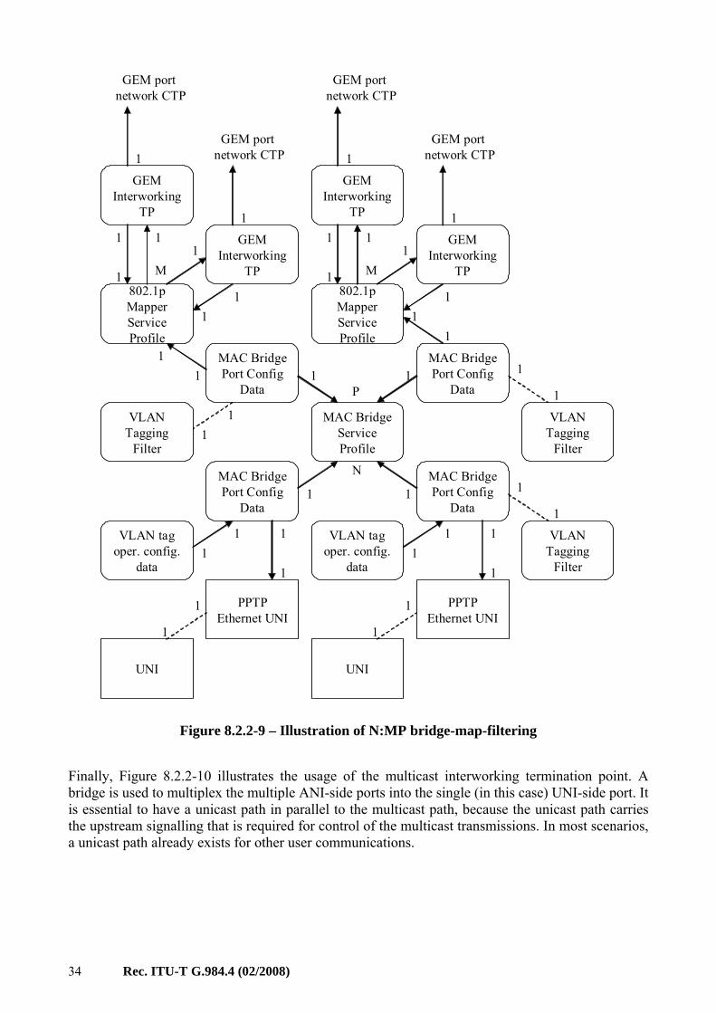
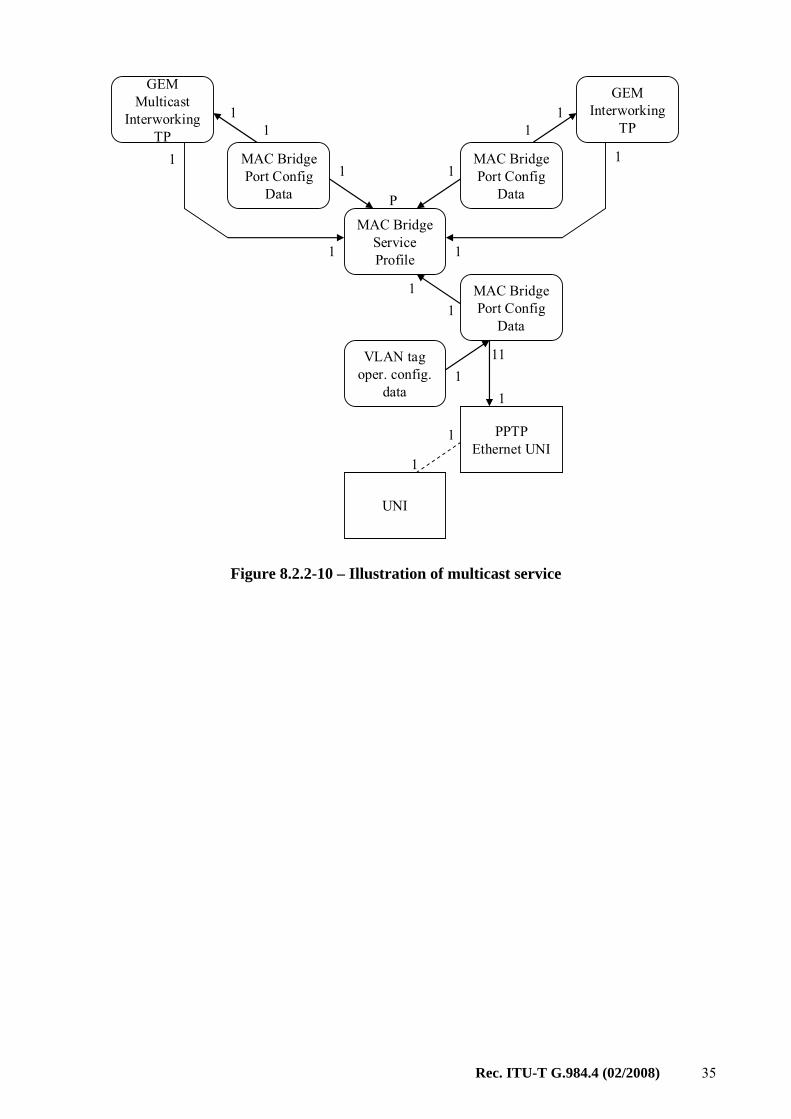
Finally, Figure 8.2.2-10 illustrates the usage of the multicast interworking termination point. A bridge is used to multiplex the multiple ANI-side ports into the single (in this case) UNI-side port. It is essential to have a unicast path in parallel to the multicast path, because the unicast path carries the upstream signalling that is required for control of the multicast transmissions. In most scenarios, a unicast path already exists for other user communications.
Rec. ITU-T G.984.4 (02/2008) 35
GEM Interworking
TP
MAC Bridge Port Config
Data
MAC Bridge Service Profile
MAC Bridge Port Config
Data
1
PPTP Ethernet UNI
1
UNI
1
1
1
1
11
11
1
GEM Multicast
InterworkingTP
MAC Bridge Port Config
Data
11
1
1
1
P
VLAN tag oper. config.
data
11
Figure 8.2.2-10 – Illustration of multicast service
36 Rec. ITU-T G.984.4 (02/2008)
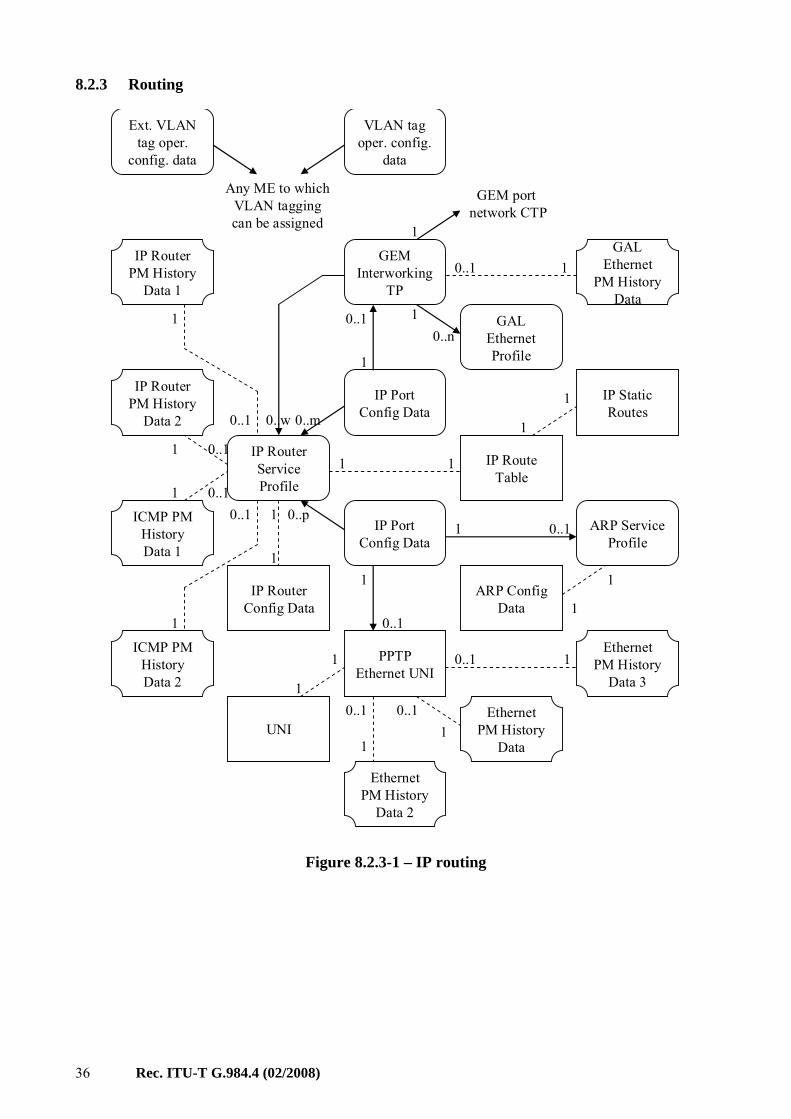
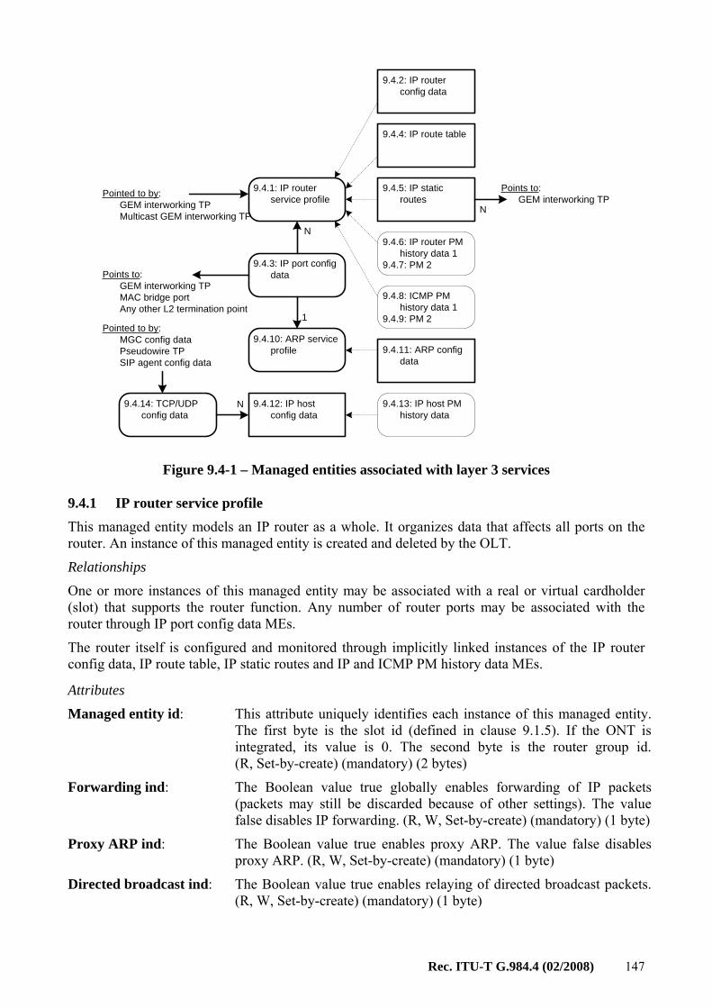
8.2.3 Routing
GEM Interworking
TP
0..p1
IP Port Config Data0..w
IP Router Service Profile
IP Port Config Data
IP Router Config Data
1
ARP Service Profile
IP Static Routes
ARP ConfigData
0..m1
1
1
1
1 0..1
1
PPTP Ethernet UNI
0..1
UNI
1
1
IP Route Table
1
1
1
0..1
0..1
1
0..1
0..1
0..11
1
1
0..1 0..1
11
1
1
GEM port network CTP
0..nGAL
Ethernet Profile
0..1 1
VLAN tag oper. config.
data
Ext. VLAN tag oper.
config. data
Any ME to which VLAN tagging can be assigned
GAL Ethernet
PM History Data
Ethernet PM History
Data
Ethernet PM History
Data 2
IP Router PM History
Data 1
IP Router PM History
Data 2
ICMP PM History Data 1
ICMP PM History Data 2
Ethernet PM History
Data 30..1 1
Figure 8.2.3-1 – IP routing
Rec. ITU-T G.984.4 (02/2008) 37
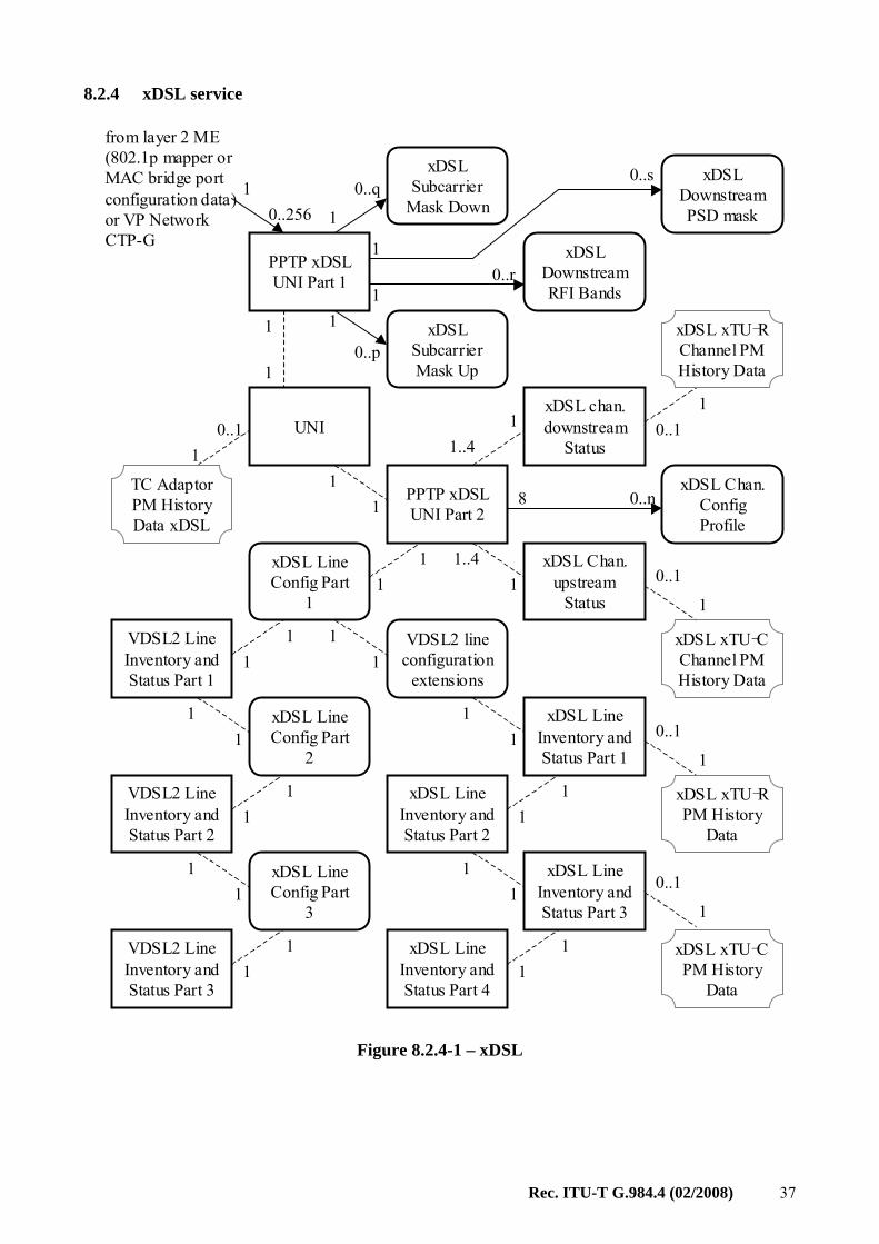
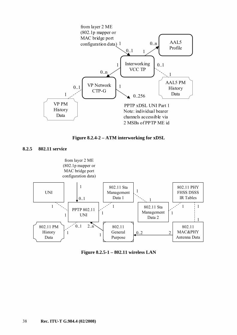
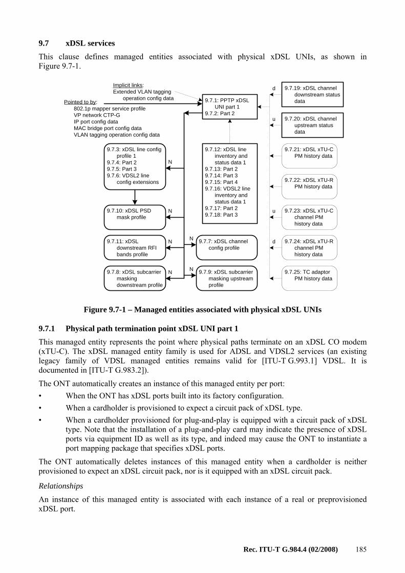
8.2.4 xDSL service
PPTP xDSLUNI Part 1
UNI
1
0..2561
PPTP xDSLUNI Part 2
xDSL Line Inventory and Status Part 2
xDSL chan. downstream
Status
xDSL Line Inventory and Status Part 1
xDSL Chan. upstream
Status
8 0..n
1
11
11
0..p
0..q
0..r
0..s
xDSL Line Config Part
3
xDSL Line Config Part
2
xDSL Line Config Part
1
xDSLDownstream RFI Bands
xDSLDownstream PSD mask
xDSLSubcarrierMask Up
xDSLSubcarrier
Mask Down
xDSL Chan. ConfigProfile
1..4
VDSL2 line configuration
extensions
VDSL2 Line Inventory and Status Part 3
xDSL Line Inventory and Status Part 3
VDSL2 Line Inventory and Status Part 1
VDSL2 Line Inventory and Status Part 2
xDSL Line Inventory and Status Part 4
1
11
11
11
10..1
1
0..11..4
1
1
0..1
1
0..1
11
11
11
11
11
1
1
10..1
1
1
11
11
from layer 2 ME (802.1p mapper or MAC bridge port configuration data) or VP Network CTP-G
xDSL xTU-RChannel PM History Data
xDSL xTU-CChannel PM History Data
xDSL xTU-RPM History
Data
xDSL xTU-CPM History
Data
TC Adaptor PM History Data xDSL
Figure 8.2.4-1 – xDSL
38 Rec. ITU-T G.984.4 (02/2008)
InterworkingVCC TP
AAL5 Profile0..1
1
from layer 2 ME (802.1p mapper or MAC bridge port configuration data)
VP Network CTP-G
AAL5 PM History
Data
VP PM History
Data
1
0..1
1
0..n
10..1
10..n
PPTP xDSL UNI Part 1Note: individual bearer channels accessible via 2 MSBs of PPTP ME id
0..256
1
Figure 8.2.4-2 – ATM interworking for xDSL
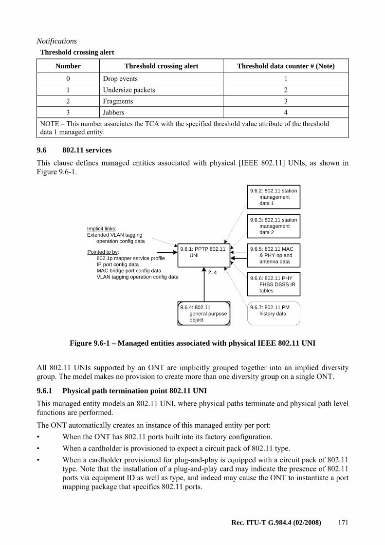
8.2.5 802.11 service
PPTP 802.11 UNI
UNI
1
1
0..1
1 802.11 StaManagement
Data 1
11
802.11 StaManagement
Data 2
802.11 MAC&PHY
Antenna Data
1
1
11
802.11 General Purpose
802.11 PHY FHSS DSSS
IR Tables
1
1
2..n20..21
0..11
802.11 PM History
Data
from layer 2 ME (802.1p mapper or MAC bridge port
configuration data)
Figure 8.2.5-1 – 802.11 wireless LAN
Rec. ITU-T G.984.4 (02/2008) 39
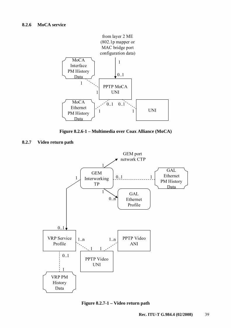
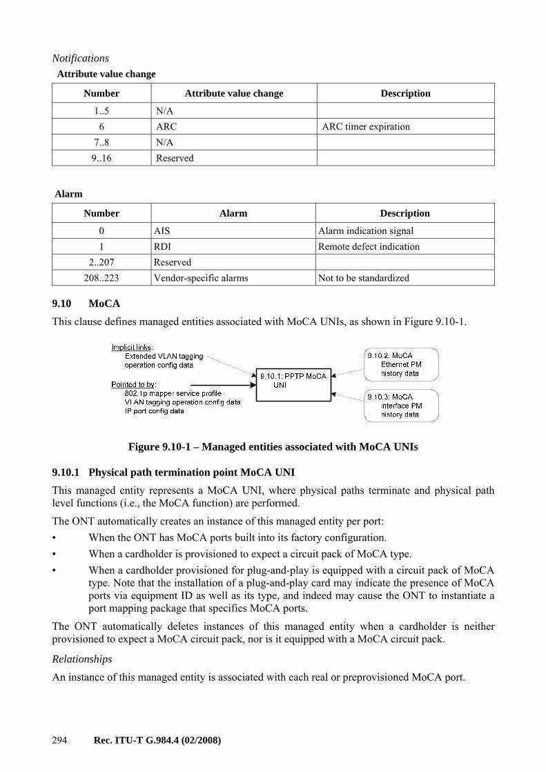
8.2.6 MoCA service
PPTP MoCAUNI
UNI
1
1
0..1
1
0..11
0..11
MoCAInterface
PM History Data
MoCAEthernet
PM History Data
from layer 2 ME (802.1p mapper or MAC bridge port
configuration data)
Figure 8.2.6-1 – Multimedia over Coax Alliance (MoCA)
8.2.7 Video return path
PPTP Video UNI
1
0..11
PPTP VideoANI
1
VRP Service Profile
1..n 1..n
1
1
GEM port network CTP
0..nGAL
Ethernet Profile
0..1 1GEM
InterworkingTP
0..1
1
GAL Ethernet
PM History Data
VRP PM History
Data
Figure 8.2.7-1 – Video return path
40 Rec. ITU-T G.984.4 (02/2008)
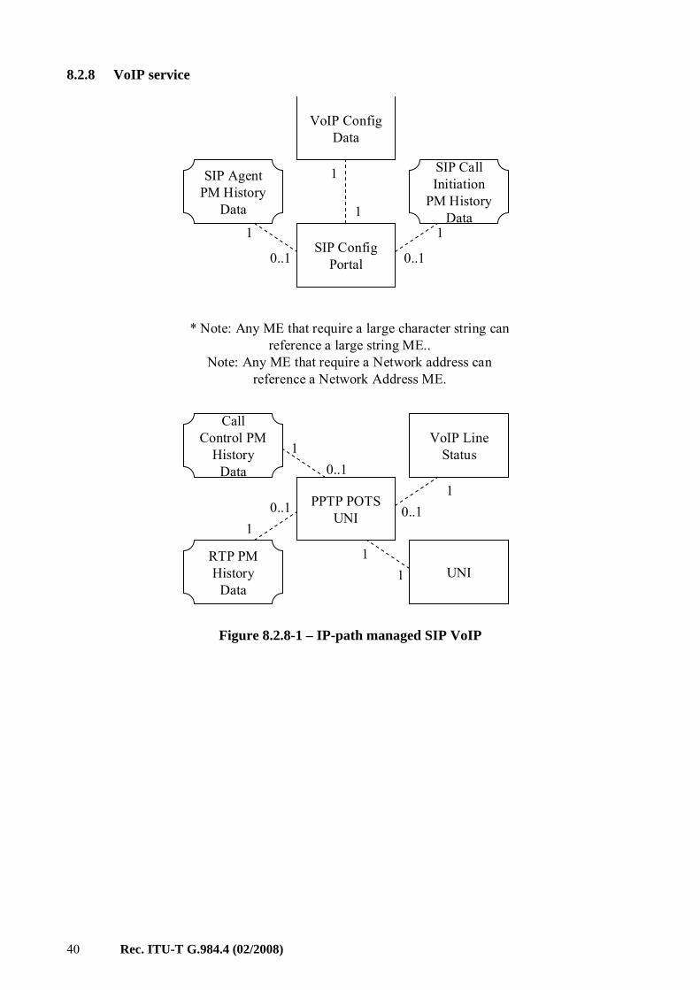
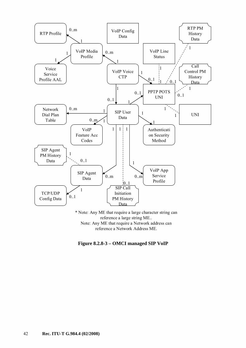
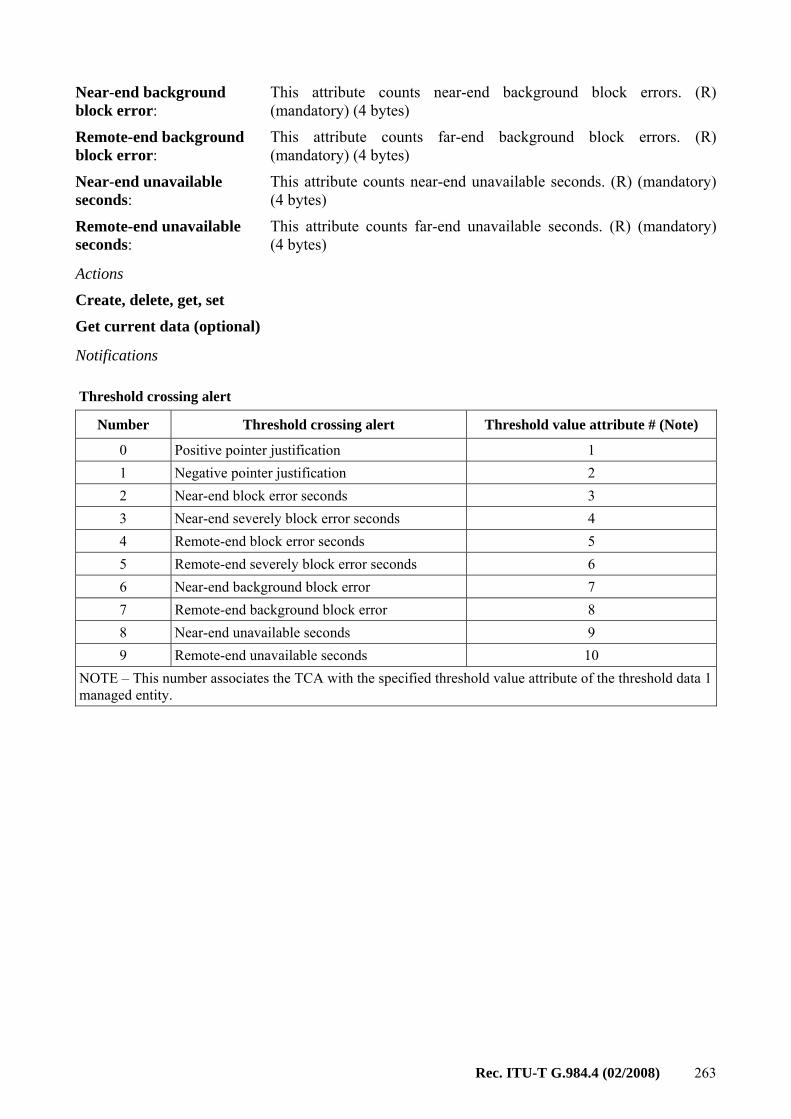
8.2.8 VoIP service
* Note: Any ME that require a large character string can reference a large string ME..
Note: Any ME that require a Network address can reference a Network Address ME.
SIP ConfigPortal
VoIP ConfigData
0..1 0..1
111
1
PPTP POTS UNI
0..1 0..11
1
1VoIP Line
Status
UNI1
1
0..1
Call Control PM
History Data
SIP Agent PM History
Data
SIP Call Initiation
PM History Data
RTP PM History
Data
Figure 8.2.8-1 – IP-path managed SIP VoIP
Rec. ITU-T G.984.4 (02/2008) 41
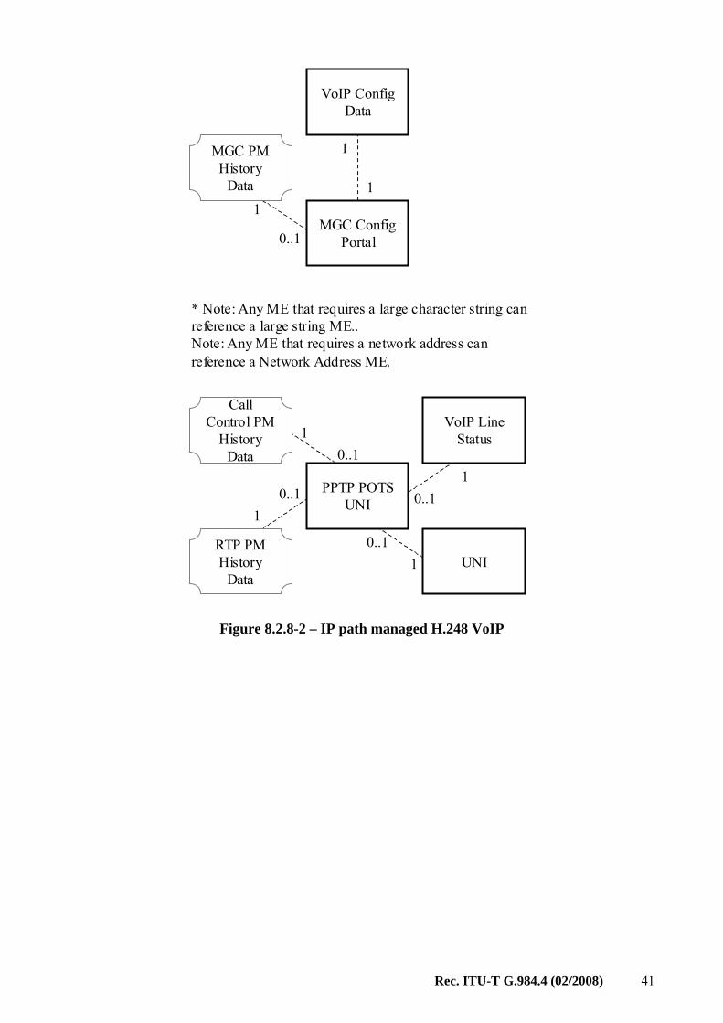
* Note: Any ME that requires a large character string can reference a large string ME..Note: Any ME that requires a network address can reference a Network Address ME.
PPTP POTS UNI
0..1 0..11
1
1VoIP Line
Status
UNI0..1
1
0..1
Call Control PM
History Data
RTP PM History
Data
MGC ConfigPortal
VoIP ConfigData
0..1
11
1MGC PM History
Data
Figure 8.2.8-2 – IP path managed H.248 VoIP
42 Rec. ITU-T G.984.4 (02/2008)
* Note: Any ME that require a large character string can reference a large string ME..
Note: Any ME that require a Network address can reference a Network Address ME.
VoIP ConfigData
0..11
1
VoIP Voice CTP
VoIP Line Status
PPTP POTS UNI
VoIP Media Profile
RTP Profile
Voice Service
Profile AAL
UNISIP User Data
Authentication Security
Method
VoIP App Service Profile
SIP Agent Data
Network Dial Plan
Table
VoIPFeature Acc
Codes
TCP/UDP Config Data
1
0..m
0..m
1
11
0..1
10..1
10..m 1
0..m0..1
0..1
0..11
1
11 1
11
0..1
1
1
1
0..m
10..m1
1
0..1
1
RTP PM History
Data
Call Control PM
History Data
SIP Call Initiation
PM History Data
SIP Agent PM History
Data
Figure 8.2.8-3 – OMCI managed SIP VoIP
Rec. ITU-T G.984.4 (02/2008) 43
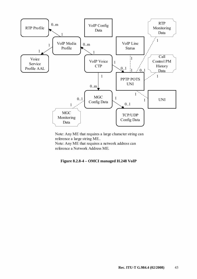
Note: Any ME that requires a large character string can reference a large string ME..Note: Any ME that requires a network address can reference a Network Address ME.
MGC Config Data
TCP/UDP Config Data
1
10..1
0..1
1
0..m
VoIP ConfigData
0..11
1
VoIP Voice CTP
VoIP Line Status
PPTP POTS UNI
VoIP Media Profile
RTP Profile
Voice Service
Profile AAL
UNI
1
0..m
0..m
1
11
0..1
11
1
1
1
RTP Monitoring
Data
Call Control PM
History Data
MGC Monitoring
Data
Figure 8.2.8-4 – OMCI managed H.248 VoIP
44 Rec. ITU-T G.984.4 (02/2008)
IP host configdata
TCP/UDP Config data
from layer 2 ME (802.1p mapper or MAC bridge port configuration data)
0..1
0..m
0..1
1
1
AuthenticationSecurity Method
Network Address
1
Any ME that requires a network address
1
11
Large stringIP host
monitoring data
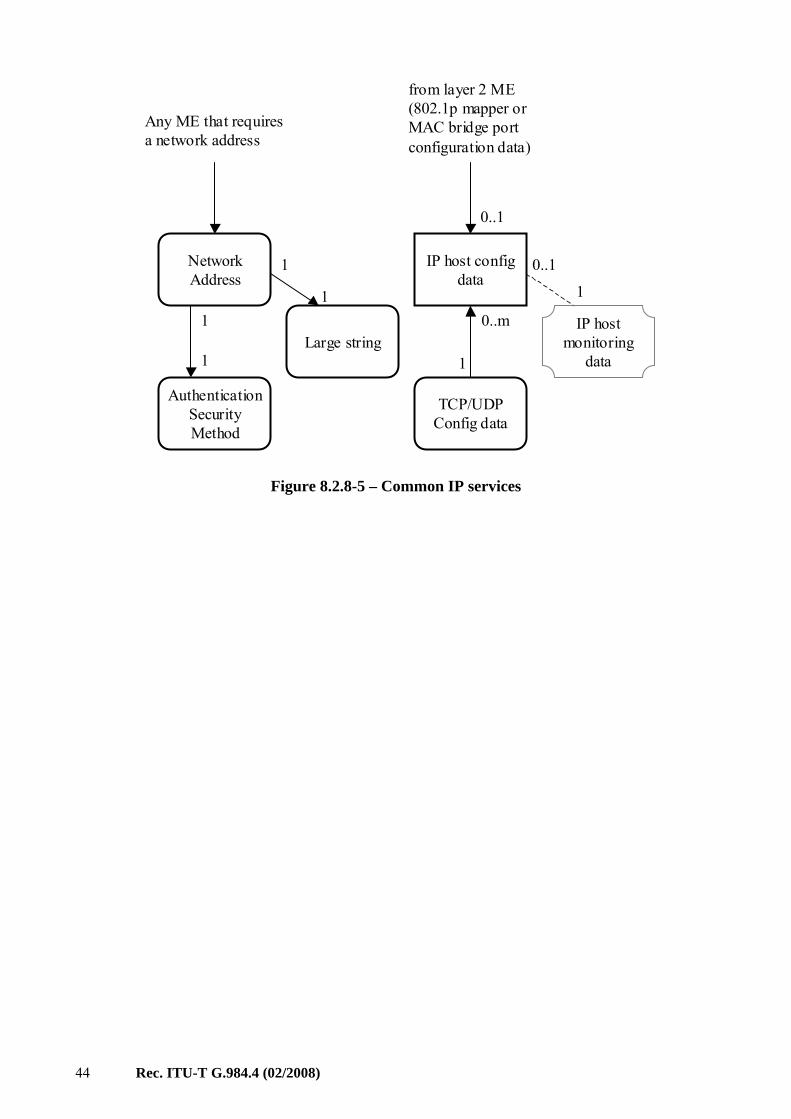
Figure 8.2.8-5 – Common IP services
Rec. ITU-T G.984.4 (02/2008) 45
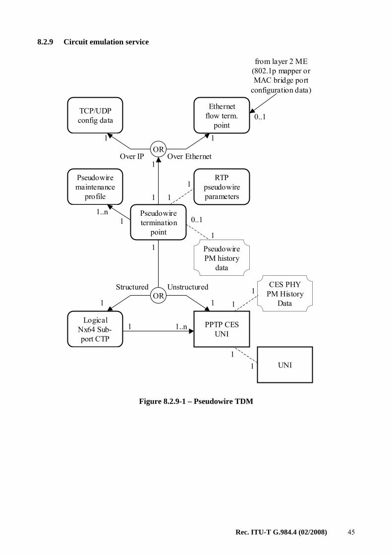
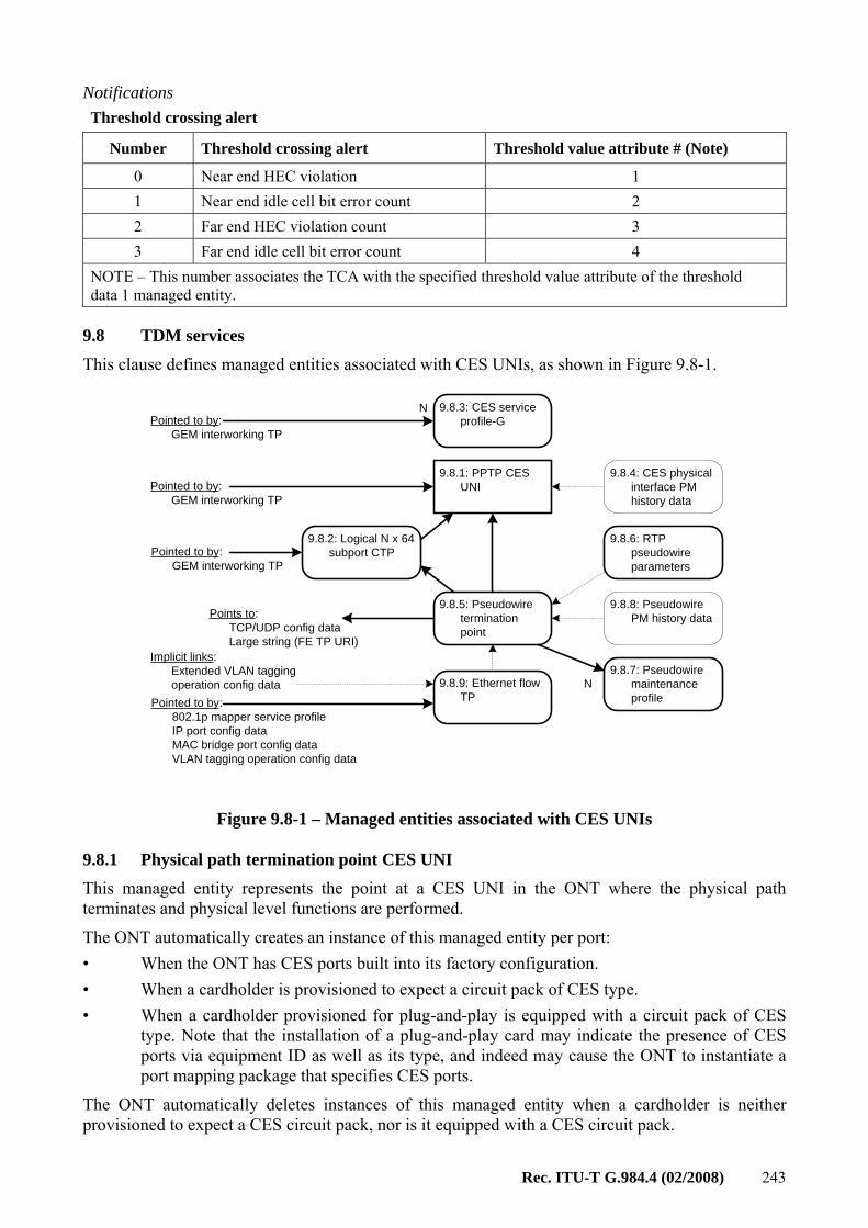
8.2.9 Circuit emulation service
Ethernet flow term.
point
Pseudowiretermination
point
Pseudowiremaintenance
profile
RTP pseudowireparameters
PPTP CES UNI
Logical Nx64 Sub-port CTP
OR
1
1
1
0..1
1
1
11..n
1..n1
1
1 1
Structured Unstructured
OR1 1
TCP/UDP config data
Over EthernetOver IP
UNI1
1
PseudowirePM history
data
from layer 2 ME (802.1p mapper or MAC bridge port
configuration data)
0..1
CES PHY PM History
Data1
1
Figure 8.2.9-1 – Pseudowire TDM
46 Rec. ITU-T G.984.4 (02/2008)
TU termination
point
Pseudowiremaintenance
profile
PPTP CES UNI
Logical Nx64 Sub-port CTP
OR
1
0..1
1
11..n
1..n1
1
1 1
Structured Unstructured
UNI1
1
TU PM history data
GEM Interworking
TP1
1
GEM port network CTP
0..n CES Profile
0..1 1CES GAL PM History
Data
0..1
CES PHY PM History
Data1
1
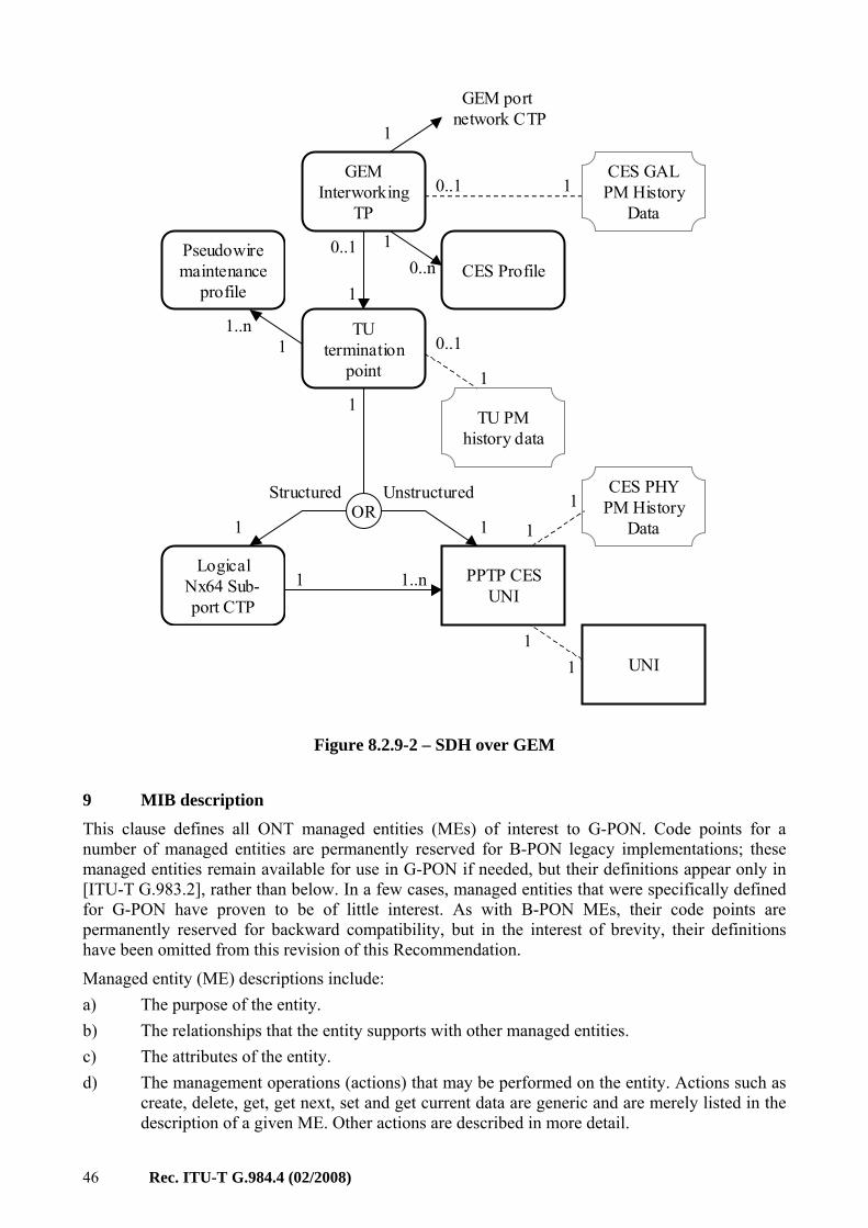
Figure 8.2.9-2 – SDH over GEM
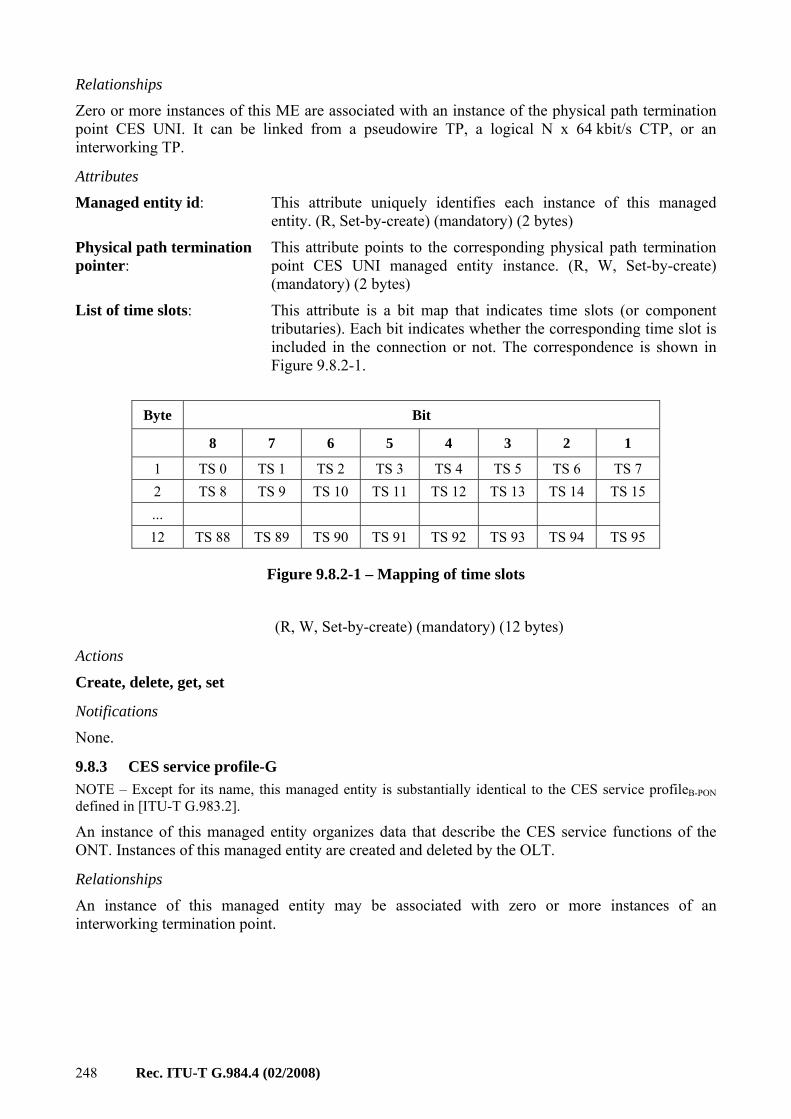
9 MIB description This clause defines all ONT managed entities (MEs) of interest to G-PON. Code points for a number of managed entities are permanently reserved for B-PON legacy implementations; these managed entities remain available for use in G-PON if needed, but their definitions appear only in [ITU-T G.983.2], rather than below. In a few cases, managed entities that were specifically defined for G-PON have proven to be of little interest. As with B-PON MEs, their code points are permanently reserved for backward compatibility, but in the interest of brevity, their definitions have been omitted from this revision of this Recommendation.
Managed entity (ME) descriptions include: a) The purpose of the entity. b) The relationships that the entity supports with other managed entities. c) The attributes of the entity. d) The management operations (actions) that may be performed on the entity. Actions such as
create, delete, get, get next, set and get current data are generic and are merely listed in the description of a given ME. Other actions are described in more detail.
Rec. ITU-T G.984.4 (02/2008) 47
e) The notifications generated by the managed entity. These may be attribute value changes (AVCs), alarms or performance monitoring threshold crossing alerts. Tables define each of these three classes as needed for each ME type.
These clauses are organized as follows: 9.1 Equipment management 9.2 ANI management 9.3 Layer 2 data services 9.4 Layer 3 data services 9.5 Ethernet services 9.6 802.11 services 9.7 xDSL services 9.8 TDM services 9.9 Voice services 9.10 MoCA 9.11 Traffic management 9.12 General purpose MEs 9.13 Miscellaneous services
A managed entity can be instantiated by the ONT autonomously or on explicit request of the OLT via a create command. Attributes of a managed entity for which no create action exists (i.e., a managed entity that is auto-instantiated by the ONT) can be (R), (W) or (R, W).
On the other hand, attributes of a managed entity for which a create action exists (i.e., a managed entity that is instantiated on explicit request by the OLT) can be either (R), (W), (R, W), (R, Set-by-create), (W, Set-by-create) or (R, W, Set-by-create). Where appropriate, this Recommendation specifies a default value, to be assigned to the attribute on instantiation of the managed entity.
The following explains each case in more detail:
(R): On instantiation of the managed entity, either autonomously or on request of the OLT via a create action, the ONT sets the attribute to a default value or to a value that reflects a current state or measurement. The OLT can only read the value of the attribute. In case of an autonomous attribute value change, the ONT may send an attribute value change notification (AVC) to the OLT.
(W): On instantiation of the managed entity, either autonomously or on request of the OLT via a create action, an initial value may or may not be specified. The OLT can only write the value of the attribute. Such an attribute never triggers an AVC notification to the OLT.
(R, W): On instantiation of the managed entity, either autonomously or on request of the OLT via a create action, the ONT sets the attribute to a default value. The OLT can both read and write the value of the attribute. In case of an autonomous attribute value change, the ONT may send an AVC notification to the OLT.
48 Rec. ITU-T G.984.4 (02/2008)
(R, Set-by-create): On instantiation of the managed entity, by necessity on request of the OLT via a create action, the ONT sets the attribute to the value specified in the create command. Subsequently, the OLT cannot change the value of the attribute. This combination is used mostly for managed entity IDs, but occasionally for attributes that cannot meaningfully change after ME creation.
(W, Set-by-create): On instantiation of the managed entity, by necessity on request of the OLT via a create action, the ONT sets the attribute to the value specified in the create command. Subsequently, the OLT can only write the value of the attribute. Such an attribute never triggers an AVC notification to the OLT.
(R, W, Set-by-create): On instantiation of the managed entity, by necessity on request of the OLT via a create action, the ONT sets the attribute to the value specified in the create command. Subsequently, the OLT can both read and write the value of the attribute. In case of an autonomous attribute value change, the ONT may send an AVC notification to the OLT. In a number of cases, it is logically impossible to change (write) the value of an attribute after the ME is created. However, chicken and egg issues can arise when several such MEs point to each other. Allowing such attributes to be set after creation is intended to avoid these issues.
The notifications generated by a managed entity stem from the following events: alarms, attribute value changes (AVCs), threshold crossing alerts (TCAs) and test results.
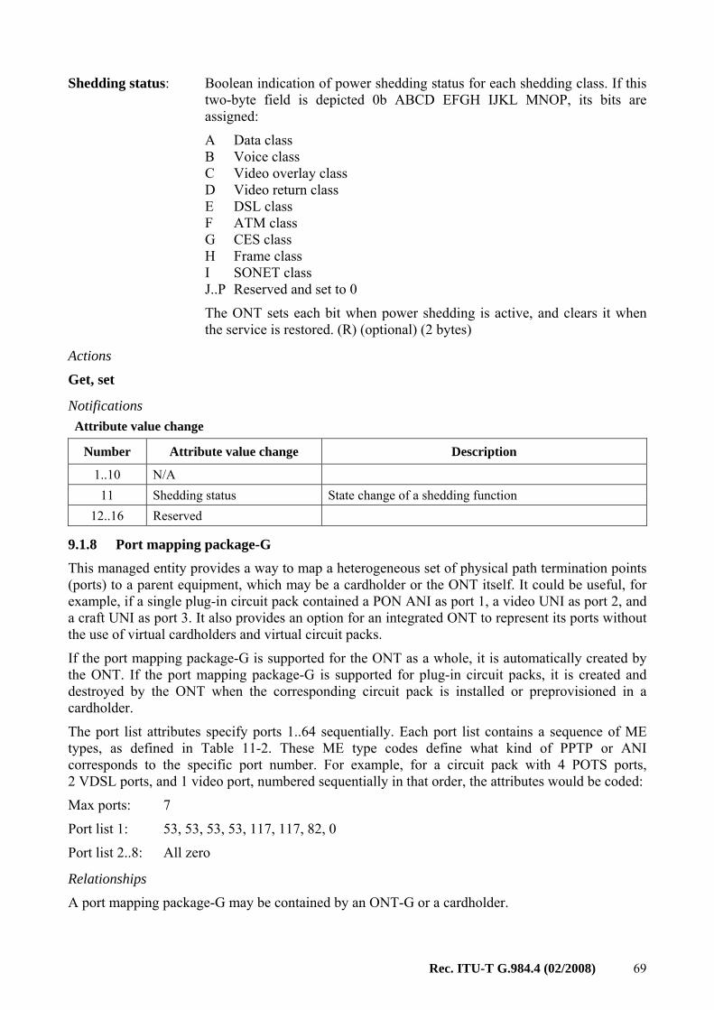
Alarms, TCAs and failures of autonomous self tests are all reported via alarm messages. The alarm reporting message contains a field of 224 bits, which is mapped to as many as 208 specific alarms by the definition of each managed entity. The last 16 bits are reserved for vendor-specific alarms and are not to be standardized. Alarm bits are numbered from 0 upward. The general schema is illustrated in the following table, where each managed entity definition may specify some of the 208 reserved points for its own alarms. Different ME types can re-use the same codepoints because the alarm report message includes the ME type (and instance).
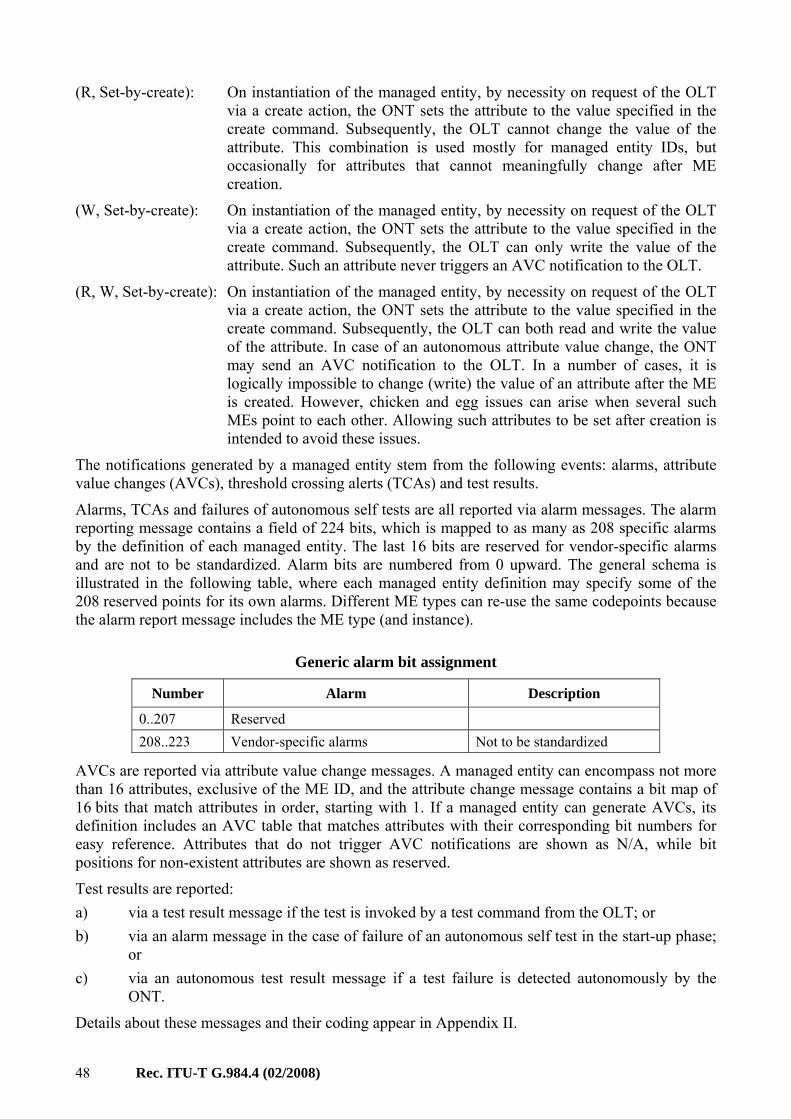
Generic alarm bit assignment
Number Alarm Description
0..207 Reserved 208..223 Vendor-specific alarms Not to be standardized
AVCs are reported via attribute value change messages. A managed entity can encompass not more than 16 attributes, exclusive of the ME ID, and the attribute change message contains a bit map of 16 bits that match attributes in order, starting with 1. If a managed entity can generate AVCs, its definition includes an AVC table that matches attributes with their corresponding bit numbers for easy reference. Attributes that do not trigger AVC notifications are shown as N/A, while bit positions for non-existent attributes are shown as reserved.
Test results are reported: a) via a test result message if the test is invoked by a test command from the OLT; or b) via an alarm message in the case of failure of an autonomous self test in the start-up phase;
or c) via an autonomous test result message if a test failure is detected autonomously by the
ONT.
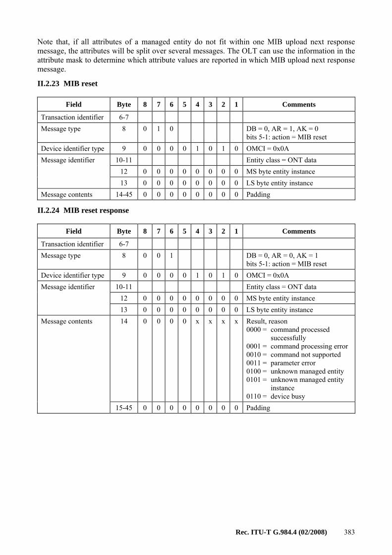
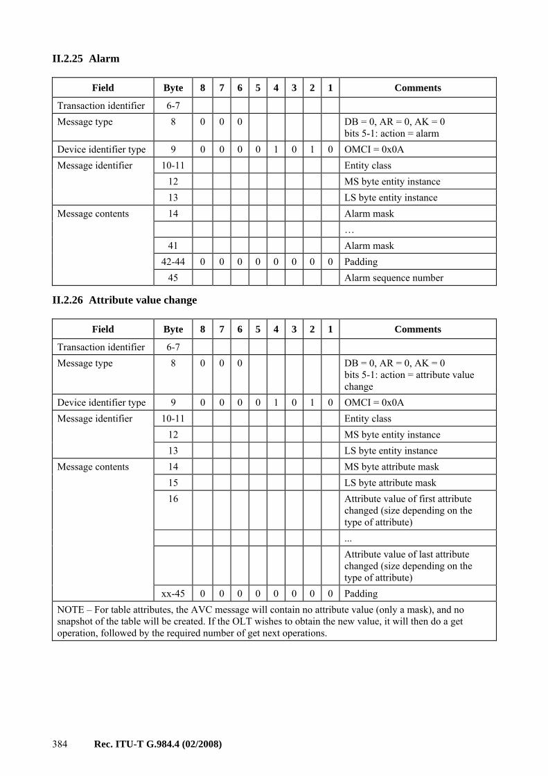
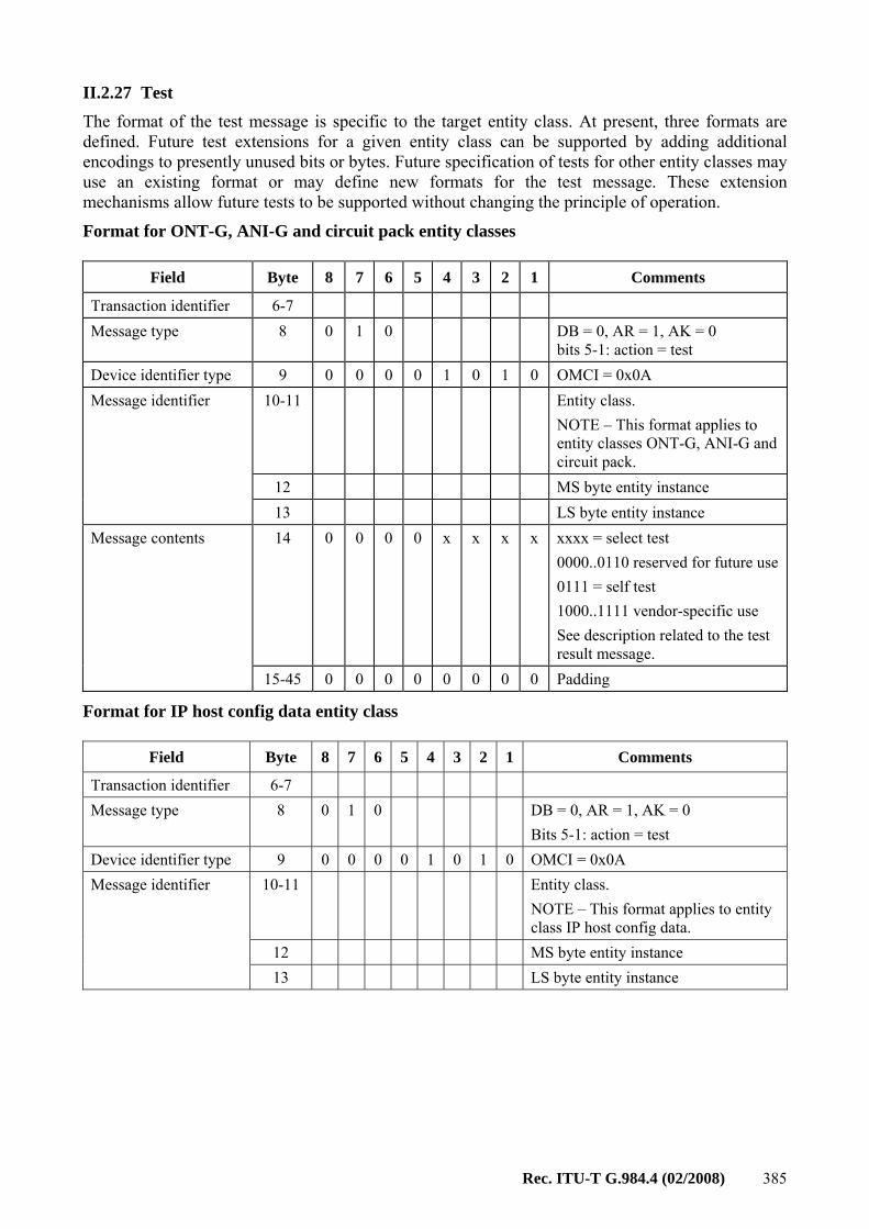
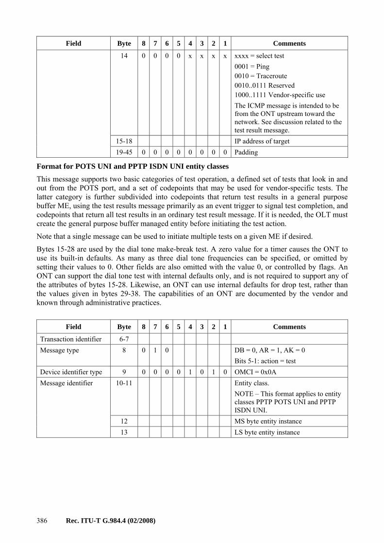
Details about these messages and their coding appear in Appendix II.
Rec. ITU-T G.984.4 (02/2008) 49
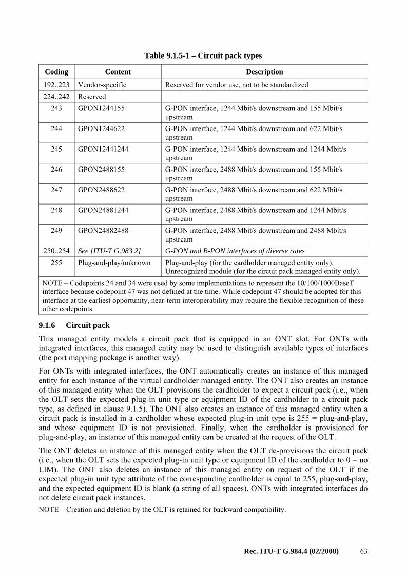
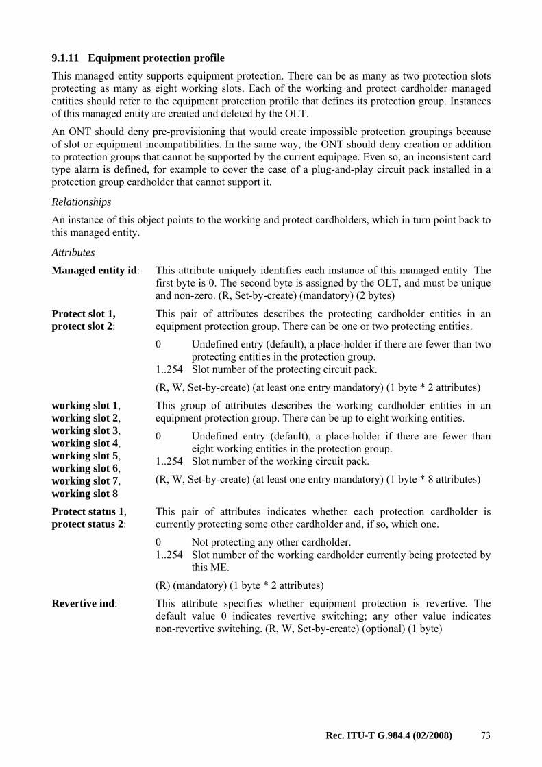
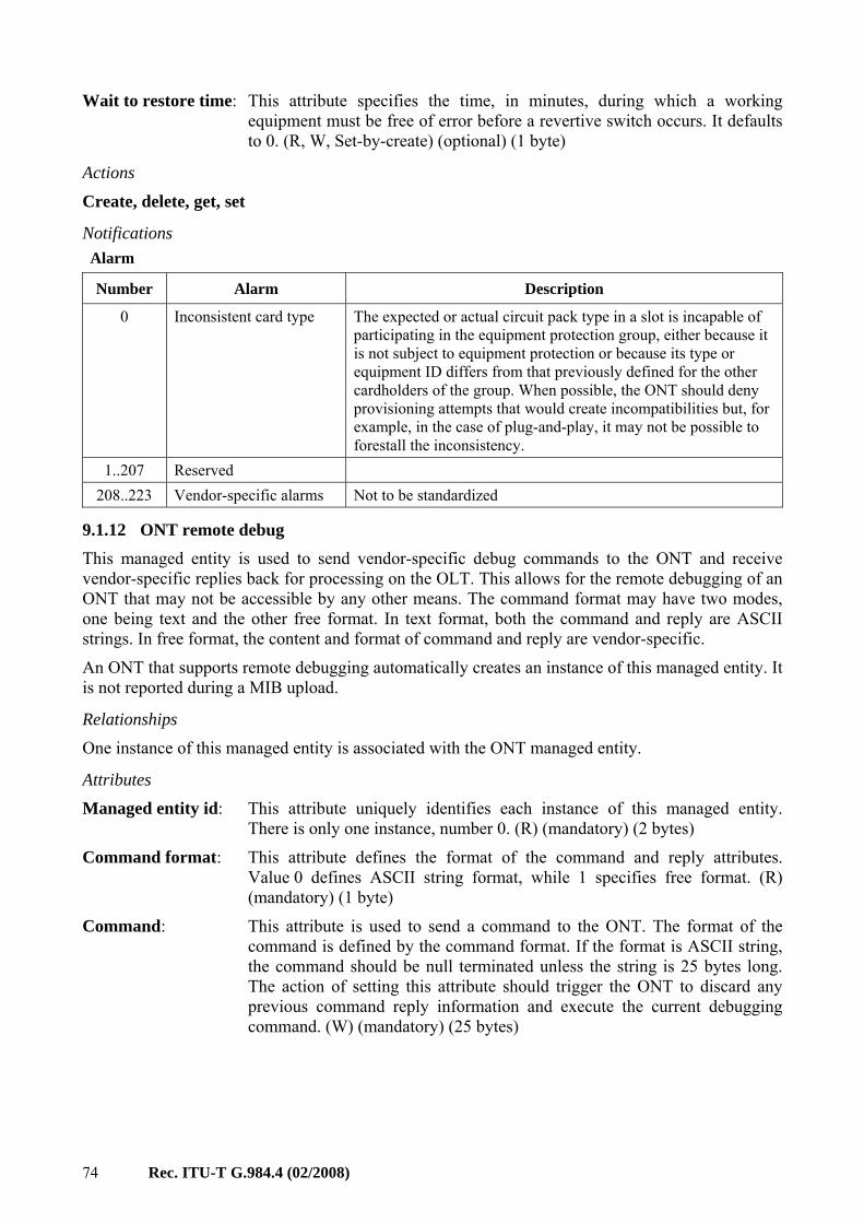
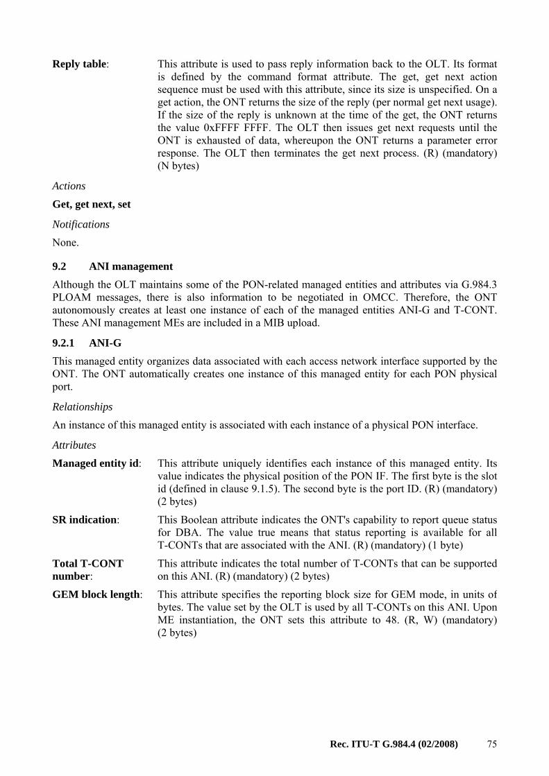
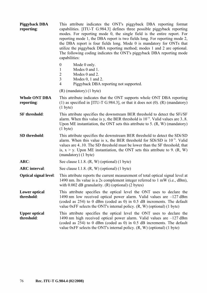
9.1 Equipment management An ONT may be physically implemented as a single module (integrated ONT) or as a shelf containing plug-in field-replaceable units. The latter construction is technically called an ONU, but this Recommendation often uses the terms interchangeably to refer to either. Except for equipment-specific features, the same criteria pertain to both versions.
An ONU with physical slots automatically instantiates cardholder MEs for each of its slots. A slot can then be populated with a circuit pack. Physical slots are recommended to number from left to right, then from bottom to top.
An integrated ONT may or may not model itself with virtual cardholders and circuit packs. If not, the ONT itself is understood to exist in virtual slot 0, since a number of MEs use the slot id as part of their identifiers.
When subscriber and PON-side physical ports are grouped into real or virtual circuit packs, each of which supports only a single type of interface, the port numbering algorithm is clear. An integrated ONT may choose not to model itself with virtual cardholders, and a complex circuit pack may have ports of several types, for example a PON ANI, a video UNI and a craft port. The port mapping package provides a flexible way to associate port numbers with a heterogeneous assortment of ports.
9.1.1 ONT-G This managed entity represents the ONT as equipment. The ONT automatically creates an instance of this managed entity. It assigns values to read-only attributes according to data within the ONT itself.
Relationships All other managed entities in this Recommendation are related directly or indirectly to the ONT-G entity.
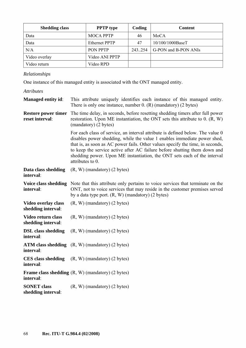
Attributes
Managed entity id: This attribute uniquely identifies each instance of this managed entity. There is only one instance, number 0. (R) (mandatory) (2 bytes)
Vendor id: This attribute identifies the vendor of the ONT. It is the same as the four most significant bytes of the ONT serial number as specified in [ITU-T G.984.3]. (R) (mandatory) (4 bytes)
Version: This attribute identifies the version of the ONT as defined by the vendor. The character value "0" indicates that version information is not available or applicable. (R) (mandatory) (14 bytes)
Serial number: The serial number is unique for each ONT. It is defined in [ITU-T G.984.3] and contains the vendor ID and version number. The first four bytes are an ASCII-encoded vendor ID four letter mnemonic. The second four bytes are a binary encoded serial number, under the control of the ONT vendor. (R) (mandatory) (8 bytes)
50 Rec. ITU-T G.984.4 (02/2008)
Traffic management option:
This attribute identifies the upstream traffic management function implemented in the ONT. There are two options:
0 Priority controlled and flexibly scheduled upstream traffic. The traffic scheduler and priority queue mechanism are used for upstream traffic.
1 Rate controlled upstream traffic. The maximum upstream traffic of each individual connection is guaranteed.
For clarification, see Appendix III.
Downstream priority queues are managed via the GEM port network CTP ME.
Upon ME instantiation, the ONT sets this attribute to the value that describes its implementation. The OLT must adapt its model to conform to the ONT's selection. (R) (mandatory) (1 byte)
VP/VC cross-connection function option:
This attribute is not used. If it is present, it should be set to 0. (R) (optional) (1 byte)
This attribute locks (1) and unlocks (0) the functions performed by this managed entity. When the administrative state is set to lock, all user functions are blocked, and alarms, TCAs and AVCs for this managed entity and all dependent managed entities are no longer generated. Selection of a default value for this attribute is outside the scope of this Recommendation. (R, W) (mandatory) (1 byte)
Operational state: This attribute reports whether the managed entity is currently capable of performing its function. Valid values are enabled (0) and disabled (1). (R) (optional) (1 byte)
Actions
Get, set
Reboot: Reboot the ONT.
Test: Test the ONT. The test action can be used either to perform equipment diagnostics or to measure parameters such as received optical power, video output level, battery voltage, etc. Extensions to the test and test response messages are defined for these purposes; refer to Appendix II.
Synchronize time: This action synchronizes the start time of all performance monitoring managed entities of the ONT with the reference time of the OLT. All counters of all monitoring managed entities are cleared to 0 and restarted. Also, the value of the interval end time attribute of the monitoring managed entities is set to 0 and restarted. See clause I.1.9 for further discussion of PM.
Notifications Test result: Test results are reported via a test result message if the test is invoked by a
test command from the OLT.
Rec. ITU-T G.984.4 (02/2008) 51
Attribute value change
Number Attribute value change Description
1 Vendor id Vendor identification 2 Version Version of ONT as defined by vendor 3 Serial number Serial number of ONT
4..7 N/A 8 Op state Operational state change
9..16 Reserved
Alarm
Number Alarm Description
0 Equipment alarm Functional failure on an internal interface 1 Powering alarm Loss of external power 2 Battery missing Battery is provisioned but missing 3 Battery failure Battery is provisioned and present but cannot recharge 4 Battery low Battery is provisioned and present but its voltage is too low 5 Physical intrusion Applies if the ONT supports detection such as door or box open 6 ONT self test failure ONT has failed autonomous self test 7 Dying gasp ONT is powering off imminently 8 Temperature yellow No service shutdown at present, but the circuit pack is operating
beyond its recommended range 9 Temperature red Some services have been shut down to avoid equipment damage.
The operational state of the affected PPTPs indicates the affected services
10 Voltage yellow No service shutdown at present, but the line power voltage is below its recommended minimum. Service restrictions may be in effect, such as permitting no more than N lines off-hook or ringing at one time
11 Voltage red Some services have been shut down to avoid power collapse. The operational state of the affected PPTPs indicates the affected services
12..207 Reserved 208..223 Vendor-specific alarms Not to be standardized
9.1.2 ONT2-G This managed entity contains additional attributes associated with the G-PON ONT. The ONT automatically creates an instance of this managed entity. Its attributes are populated according to the data within the ONT itself.
Relationships This managed entity is paired with the ONT-G entity.
52 Rec. ITU-T G.984.4 (02/2008)
Attributes Managed entity id: This attribute uniquely identifies each instance of this managed entity.
There is only one instance, number 0. (R) (mandatory) (2 bytes)
Equipment id:
This attribute may be used to identify the specific type of ONT. In North America, this may be the equipment CLEI code. (R) (optional) (20 bytes)
OMCC version: This attribute identifies the version of the OMCC protocol being used by the ONT. This allows the OLT to manage a network with ONTs that support different OMCC versions. Release levels of this Recommendation may be supported with the following code points:
0x80 G.984.4 06/04. NOTE – For historic reasons, this codepoint may also appear in ONTs
that support later versions.
0x81 G.984.4 Amd.1 (06/05).
0x82 G.984.4 Amd.2 (03/06).
0x83 G.984.4 Amd.3 (12/06).
0x84 G.984.4 (02/08).
(R) (mandatory) (1 byte)
Vendor product code: This attribute provides a vendor-specific product code for the ONT. (R) (optional) (2 bytes)
Security capability: This attribute advertises the security capabilities of the ONT. The following codepoints are defined:
0 Reserved.
1 AES encryption of the downstream payload supported.
2..255 Reserved.
(R) (mandatory) (1 byte)
Security mode: This attribute specifies the current security mode of the ONT. All secure GEM ports in an ONT must use the same security mode at any given time. The following codepoints are defined:
0 Reserved.
1 AES algorithm used for unicast traffic.
2..255 Reserved.
Upon ME instantiation, the ONT sets this attribute to 1, AES. If new encryption modes are standardized, then AES will be the default, and the new modes will be settable via writing to this attribute. This does not mean that any channels are encrypted; that process is negotiated at the PLOAM layer. It only signifies that AES is the security mode to be used on any channels that the OLT may choose to encrypt. (R, W) (mandatory) (1 byte)
Rec. ITU-T G.984.4 (02/2008) 53
Total priority queue number:
This attribute reports the total number of priority queues that are not associated with a circuit pack, but with the ONT in its entirety. The maximum value is 0x0FFF. Upon ME instantiation, the ONT sets this attribute to the value that represents its capabilities. (R) (mandatory) (2 bytes)
Total traffic scheduler number:
This attribute reports the total number of traffic schedulers that are not associated with a circuit pack, but with the ONT in its entirety. The ONT supports null function, HOL scheduling and WRR from the priority control and guarantee of minimum rate control points of view, respectively. If the ONT has no traffic schedulers, this attribute is 0. (R) (mandatory) (1 byte)
Mode: This attribute identifies whether the ONT can operate in ATM-only mode (0), GEM-only mode (1), or both ATM and GEM mode (2). ATM mode is deprecated; this attribute should always be set to 1. (R) (mandatory) (1 byte)
Total GEM port-ID number:
This attribute reports the total number of GEM port-IDs supported by the ONT. The maximum value is 0x0FFF. Upon ME instantiation, the ONT sets this attribute to the value that represents its capabilities. (R) (optional) (2 bytes)
SysUpTime: This attribute counts the 10 ms intervals since the ONT was last initialized. It rolls over to 0 when full (See [b-IETF RFC 1213]). (R) (optional) (4 bytes)
Actions
Get, set
Notifications Attribute value change
Number Attribute value change Description
1 N/A 2 OMCC version OMCC version supported in the ONT
3..9 N/A 10..16 Reserved
9.1.3 ONT data This managed entity models the MIB itself. Clause I.1.2 explains the use of this managed entity with respect to MIB synchronization. Clause I.1.4 explains the alarm synchronization process, in which the get alarm messages are directed to the ONT data managed entity.
The ONT automatically creates an instance of this managed entity, and updates the associated attributes according to data within the ONT itself.
Relationships
One instance of this managed entity is contained in an ONT.
54 Rec. ITU-T G.984.4 (02/2008)
Attributes Managed entity id: This attribute uniquely identifies each instance of this managed entity.
There is only one instance, number 0. (R) (mandatory) (2 bytes)
MIB data sync: This attribute is used to check the alignment of the MIB of the ONT with the corresponding MIB in the OLT. MIB data sync relies on this attribute, which is a sequence number that can be checked by the OLT to see if the MIB snapshots for the OLT and ONT match. Refer to clause I.1.1 for a detailed description of this attribute. Upon ME instantiation, the ONT sets this attribute to 0. (R, W) (mandatory) (1 byte)
Actions
Get, set
Get all alarms: Latch a snapshot (i.e., copy) of the current alarm statuses of all managed entities and reset the alarm message counter.
Get all alarms next: Get the latched alarm status of the next managed entity within the current snapshot.
MIB reset: Reset the MIB data sync attribute to 0 and reset the MIB of the ONT to its default state. This default MIB consists of one instance of the ONT-G managed entity, one instance of the ONT data managed entity, two instances of the software image managed entity, zero or more instances of the cardholder managed entity, and zero or more instances of the priority queue-G managed entity (for the priority queues that reside in the ONT).
MIB upload: Latch a snapshot (i.e., copy) of the current MIB. Not every managed entity or every attribute is included in a MIB upload. Performance monitoring history data MEs are excluded; table attributes are excluded. Other MEs and attributes, such as the PPTP for the local craft terminal, are excluded as documented in their specific definitions.
MIB upload next: Get the latched attribute values of the managed entity within the current snapshot.
Notifications
None.
9.1.4 Software image This managed entity models an executable software image stored in the ONT.
The ONT automatically creates two instances of this managed entity upon the creation of each managed entity that contains independently-manageable software, either the ONT itself or an individual circuit pack. The ME attributes are populated according to data within the ONT or the circuit pack.
Some pluggable equipments may contain no software. Others may contain software that is intrinsically bound to the ONT's own software image. No software image ME need exist for such equipments, though it may be convenient for the ONT to create them to support software version audit from the OLT. In this case, the dependent MEs would support only the get action.
A slot may contain various equipments over its lifetime, and if software image MEs exist, the ONT must automatically create and delete them as the equipage changes.
When controller packs are duplicated, each can be expected to contain two software image MEs, managed through reference to the individual controller packs themselves. When this occurs, the
Rec. ITU-T G.984.4 (02/2008) 55
ONT should not have a global pair of software images MEs (instance 0), since an action (download, activate, commit) directed to instance 0 would be ambiguous.
Relationships Two instances of the software image managed entity are associated with each instance of the ONT or circuit pack whose software is independently managed.
Attributes
Managed entity id: This attribute uniquely identifies each instance of this managed entity. The two-byte value indicates the physical location of the software image. The first byte identifies the ME instance (ONT (0) or slot (1..254)) containing the associated software image ME. The second byte distinguishes between the two software image ME instances (0..1). (R) (mandatory) (2 bytes)
Version: This attribute identifies the version of the software. (R) (mandatory) (14 bytes)
Is committed: This attribute indicates whether the associated software image is committed (1) or uncommitted (0). By definition, the committed software image is loaded and executed upon reboot of the ONT and/or circuit pack. During normal operation, one software image is always committed, while the other is uncommitted. Under no circumstances are both software images allowed to be committed at the same time. On the other hand, both software images could be uncommitted at the same time if both were invalid. Upon ME instantiation, instance 0 is initialized to committed, while instance 1 is initialized to uncommitted (that is, the ONT ships from the factory with image 0 committed). (R) (mandatory) (1 byte)
Is active: This attribute indicates whether the associated software image is active (1) or inactive (0). By definition, the active software image is one that is currently loaded and executing in the ONT or circuit pack. Under normal operation, one software image is always active while the other is inactive. Under no circumstances are both software images allowed to be active at the same time. On the other hand, both software images could be inactive at the same time if both were invalid. (R) (mandatory) (1 byte)
Is valid: This attribute indicates whether the associated software image is valid (1) or invalid (0). By definition, a software image is valid if it has been verified to be an executable code image. The verification mechanism is not subject to standardization; however, at a minimum it must include a data integrity (CRC) check of the entire code image. Upon ME instantiation, the ONT validates the associated code image and sets this attribute according to the result. (R) (mandatory) (1 byte)
Actions
Get NOTE – Figure 9.1.4-1 illustrates the life cycle of software images under the following actions. State S0 is a conceptual initialization state when neither of the software images is valid (i.e., executable). During S0, the OMCC is not functional.
All of the following actions are mandatory for ONTs with remotely manageable software.
56 Rec. ITU-T G.984.4 (02/2008)
Start download: Initiate a software download sequence. This action is valid only for a software image that is currently inactive and uncommitted (i.e., not selected as the boot image).
Download section: Download a section of a software image. This action is valid only for a software image that is currently being downloaded (image 1 in state S2, image 0 in state S2').
End download: Signal the completion of a download sequence, providing both CRC and version information for final verification of a downloaded software image. This action is valid only for a software image that is currently being downloaded (image 1 in state S2, image 0 in state S2').
Activate image: Load/execute a valid software image. When this action is applied to a software image that is currently inactive, execution of the current code image is suspended, the associated software image is loaded from non-volatile memory, and execution of this new code image is initiated (that is, the associated entity re-boots on the previously inactive image). When this action is applied to a software image that is already active, a soft restart is performed. The software image is not reloaded from non-volatile memory; the current volatile code image is simply restarted. This action is only valid for a valid software image.
Commit image: Select a valid software image to be the default image to be loaded and executed by the boot code upon start-up (i.e., set the is committed attribute value to 1 for the associated software image ME and set the is committed attribute value to 0 for the other software image). This action is only valid for a valid software image.
Notifications None.
Rec. ITU-T G.984.4 (02/2008) 57
Figure 9.1.4-1 – Software image state diagram
58 Rec. ITU-T G.984.4 (02/2008)
9.1.5 Cardholder The cardholder represents the fixed equipment slot configuration of the ONT. One or more of these entities is contained in the ONT. Each cardholder can contain 0 or 1 circuit packs; the circuit pack models equipment information that can change over the lifetime of the ONT, e.g., through replacement.
An instance of this managed entity exists for each physical slot in an ONT that has pluggable circuit packs. One or more instances of this managed entity may also exist in an integrated ONT, to represent virtual slots. Instances of this managed entity are created automatically by the ONT, and the status attributes are populated according to data within the ONT itself.
There is potential for conflict in the semantics of the expected plug-in unit type, the expected port count and the expected equipment id, both when the slot is not populated and when a new circuit pack is inserted. The expected plug-in unit type and the plug-in type mismatch alarm are mandatory, although plug-and-play/unknown (circuit pack type 255) may be used as a way to minimize their significance. It is recommended that an ONT deny the provisioning of inconsistent combinations of expected equipment attributes.
When a circuit pack is plugged into a cardholder, or when a cardholder is preprovisioned to expect a circuit pack of a given type, it may trigger the ONT to instantiate a number of managed entities and update the values of others, depending on the circuit pack type. The ONT may also delete a variety of other managed entities when a circuit pack is reprovisioned to expect no circuit pack or a circuit pack of a different type. These actions are described in the definitions of the various managed entities.
Expected equipment id and expected port count are alternate ways to trigger the same preprovisioning effects. These tools may be useful if an ONT is prepared to accept more than one circuit pack of a given type but with different port counts, or if a circuit pack is a hybrid that matches none of the types in Table 9.1.5-1, but whose identification (e.g., part number) is known.
Relationships An ONT may contain one or more instances of the cardholder, each of which may contain an instance of the circuit pack managed entity. The slot id, real or virtual, is a fundamental identification mechanism for managed entities with some relationship to physical location.
Attributes Managed entity id: This attribute uniquely identifies each instance of this managed entity. The
ONT sets the first byte of this two-byte identifier to:
0 if the ONT contains pluggable equipment modules; 1 if the ONT is a single integrated equipment.
The second byte of this identifier is the slot number. In integrated ONTs, this byte may be used as a virtual slot or set to 0 to indicate a universal pseudo-slot.
Slot numbering schemes differ among vendors. It is only required that slot numbers be unique across the ONT. Up to 254 equipment slots are supported in the range 1..254 (Note 1). The value 0 is reserved to indicate a universal pseudo-slot. The value 255 is also reserved. (R) (mandatory) (2 bytes) NOTE 1 – Some xDSL managed entities use the two most significant bits of the slot number for other purposes. An ONT that supports these services may have slot limitations or restrictions.
Rec. ITU-T G.984.4 (02/2008) 59
Actual plug-in unit type:
This attribute is equal to the type of the circuit pack in the cardholder or 0 if the cardholder is empty. This attribute is then redundant with the type attribute of the circuit pack managed entity. Circuit pack types are defined in Table 9.1.5-1. (R) (mandatory) (1 byte)
The three following attributes permit the OLT to specify its intentions for future equipage of a slot. Once some or all of these are set, the ONT can proceed to instantiate circuit pack and PPTP MEs, along with other predeterminable MEs, and allow the OLT to create related discretionary MEs, thereby supporting service preprovisioning.
Expected plug-in unit type:
This attribute provisions the type of circuit pack for the slot. For type coding, see Table 9.1.5-1. The value 0 means that the cardholder is not provisioned to contain a circuit pack. The value 255 means that the cardholder is configured for plug-and-play. Upon ME instantiation, the ONT sets this attribute to 0. For integrated interfaces, this attribute may be used to represent the type of interface. (R, W) (mandatory) (1 byte)
Expected port count: This attribute permits the OLT to specify the number of ports it expects in a circuit pack. Prior to provisioning by the OLT, the ONT initializes this attribute to 0. (R, W) (optional) (1 byte)
Expected equipment id:
This attribute provisions the specific type of expected circuit pack. This attribute applies only to ONTs that do not have integrated interfaces. In North America, this may be the expected equipment CLEI code. Upon ME instantiation, the ONT sets this attribute to all spaces. (R, W) (optional) (20 bytes)
Actual equipment id: This attribute identifies the specific type of circuit pack, once it is installed. This attribute applies only to ONTs that do not have integrated interfaces. In North America, this may be the equipment CLEI code. When the slot is empty or the equipment ID is not known, this attribute should be set to all spaces. (R) (optional) (20 bytes)
Protection profile pointer:
This attribute indicates an equipment protection profile that may be associated with the cardholder. Its value is the least significant byte of the managed entity ID of the equipment protection profile with which it is associated, or 0 if equipment protection is not used. (R) (optional) (1 byte)
Invoke protection switch:
The OLT may use this attribute to control equipment protection switching. Code points have the following meaning when set by the OLT:
0 Release protection switch. 1 Operate protection switch, protect cardholder unspecified. 2 Operate protection switch, use first protect cardholder. 3 Operate protection switch, use second protect cardholder.
The ONT should deny attempts to switch to an unequipped, defective or already active protection cardholder.
Upon the get action from the OLT, this attribute should return the current value of the actual protection configuration. Code points are as defined above, except that the value 1 is never returned.
When circuit packs that support a PON IF function are switched, the response should be returned on the same PON that received the command. However, the OLT should also be prepared to accept a response on the redundant PON. (R, W) (optional) (1 byte)
60 Rec. ITU-T G.984.4 (02/2008)
Actions
Get, set
Notifications Attribute value change
Number Attribute value change Description
1 Actual type Actual type of circuit pack in cardholder 2..4 N/A
5 Actual equipment id Actual equipment ID of circuit pack in cardholder 6..7 N/A
8..16 Reserved
Alarm: If no circuit pack is configured or if the cardholder is configured for
plug-and-play with no expected equipment ID, no alarms are raised. No alarms are defined for ONTs with integrated interfaces.
Number Alarm Description
0 Plug-in LIM missing alarm
Configured circuit pack is not present. If the plug-in LIM missing alarm is active, none of the mismatch alarms are declared.
1 Plug-in type mismatch alarm
Inserted circuit pack is wrong type
2 Improper card removal Circuit pack has been removed without being de-provisioned. This is a redundant alarm that helps the OLT distinguish between transitions from state S2 to state S1 (Figure 9.1.5-1) and transitions from state S4 to state S1. This alarm is sent only when a transition occurs from state S2 to state S1.
3 Plug in equipment id mismatch alarm
Inserted circuit pack has wrong equipment ID
4 Protection switch An autonomous equipment protection switch has occurred. This notification is reported by the protected cardholder.
5..207 Reserved 208..223 Vendor-specific Not to be standardized
Figure 9.1.5-1 is a state diagram that describes insertion and removal of a particular circuit pack into/from a cardholder that is provisioned to a specific type or to plug-and-play. NOTE 2 – The state diagram is not applicable for ONTs with integrated interfaces.
Rec. ITU-T G.984.4 (02/2008) 61
Figure 9.1.5-1 – Cardholder state diagram
Some of the following circuit pack types are obsolete in G-PON applications. Their code points and definitions are reserved for backward compatibility but, in the interest of brevity, they are not listed.
62 Rec. ITU-T G.984.4 (02/2008)
Table 9.1.5-1 – Circuit pack types
Coding Content Description
0 No LIM Default value 1..12 See [ITU-T G.983.2] Various ATM-based UNIs
13 C1.5 (DS1) 1.544 Mbit/s local (T-interface) module 14 C2.0 (E1) 2.048 Mbit/s local (T-interface) module 15 C6.3 (J2) 6.312 Mbit/s local (T-interface) module 16 C-DS1/E1 Configurable DS1/E1 module 17 C-DS1/E1/J1 Configurable DS1/E1/J1 module 18 C6.3U (J2) 6.312 Mbit/s remote (U-interface) module 19 C192k 192 kbit/s local (T-interface) module 20 C44.7 (DS3) 44.736 Mbit/s local (T-interface) module 21 C34.3 (E3) 34.368 Mbit/s local (T-interface) module 22 10BaseT 10 BaseT Ethernet LAN IF 23 100BaseT 100 BaseT Ethernet LAN IF 24 10/100BaseT 10/100 BaseTx Ethernet LAN IF (Note)
25..27 See [ITU-T G.983.2] Various non-Ethernet LAN technologies 28 C1.5 (J1) 1.544 Mbit/s local (T-interface) module 29 A150SMF SONET ATM OC-3 SMF UNI 30 A150MMF SONET ATM OC-3 MMF UNI 31 A150UTP SONET ATM OC-3 UTP UNI 32 POTS Plain old telephony service 33 ISDN-BRI ISDN basic rate interface 34 Gigabit optical Ethernet Gigabit Ethernet optical IF (Note) 35 xDSL xDSL IF 36 SHDSL SHDSL IF 37 VDSL VDSL IF ([ITU-T G.993.1]) 38 Video service Video module 39 LCT Local craft terminal interface 40 802.11 [IEEE 802.11] interface 41 xDSL/POTS Combination xDSL and POTS interfaces 42 VDSL/POTS Combination VDSL ([ITU-T G.993.1]) and POTS interfaces 43 Common equipment Circuit packs such as removable power supply modules or ONU
controllers 44 Combined video UNI and
PON interface Circuit pack that combines both functions
45 Mixed services equipment Circuit pack with several types of ANI and/or UNI. Suggested for use with the port mapping package-G managed entity.
46 MoCA MoCA 47 10/100/1000BaseT 10/100/1000 BaseTx Ethernet LAN IF (Note)
48.. 191 Reserved
Rec. ITU-T G.984.4 (02/2008) 63
Table 9.1.5-1 – Circuit pack types
Coding Content Description
192..223 Vendor-specific Reserved for vendor use, not to be standardized 224..242 Reserved
250..254 See [ITU-T G.983.2] G-PON and B-PON interfaces of diverse rates 255 Plug-and-play/unknown Plug-and-play (for the cardholder managed entity only).
Unrecognized module (for the circuit pack managed entity only). NOTE – Codepoints 24 and 34 were used by some implementations to represent the 10/100/1000BaseT interface because codepoint 47 was not defined at the time. While codepoint 47 should be adopted for this interface at the earliest opportunity, near-term interoperability may require the flexible recognition of these other codepoints.
9.1.6 Circuit pack This managed entity models a circuit pack that is equipped in an ONT slot. For ONTs with integrated interfaces, this managed entity may be used to distinguish available types of interfaces (the port mapping package is another way).
For ONTs with integrated interfaces, the ONT automatically creates an instance of this managed entity for each instance of the virtual cardholder managed entity. The ONT also creates an instance of this managed entity when the OLT provisions the cardholder to expect a circuit pack (i.e., when the OLT sets the expected plug-in unit type or equipment ID of the cardholder to a circuit pack type, as defined in clause 9.1.5). The ONT also creates an instance of this managed entity when a circuit pack is installed in a cardholder whose expected plug-in unit type is 255 = plug-and-play, and whose equipment ID is not provisioned. Finally, when the cardholder is provisioned for plug-and-play, an instance of this managed entity can be created at the request of the OLT.
The ONT deletes an instance of this managed entity when the OLT de-provisions the circuit pack (i.e., when the OLT sets the expected plug-in unit type or equipment ID of the cardholder to 0 = no LIM). The ONT also deletes an instance of this managed entity on request of the OLT if the expected plug-in unit type attribute of the corresponding cardholder is equal to 255, plug-and-play, and the expected equipment ID is blank (a string of all spaces). ONTs with integrated interfaces do not delete circuit pack instances. NOTE – Creation and deletion by the OLT is retained for backward compatibility.
64 Rec. ITU-T G.984.4 (02/2008)
Relationships An instance of this managed entity is contained by an instance of the cardholder managed entity.
Attributes Managed entity id: This attribute uniquely identifies each instance of this managed entity. Its
value is the same as that of the cardholder managed entity containing this circuit pack instance. (R, Set-by-create (if applicable)) (mandatory) (22 bytes)
Type: This attribute identifies the circuit pack type. This attribute is a code as defined in Table 9.1.5-1. The value 255 means unknown or undefined, i.e., the inserted circuit pack is not recognized by the ONT or is not mapped to an entry in Table 9.1.5-1. In the latter case, the equipment ID attribute may contain inventory information. Upon autonomous ME instantiation, the ONT sets this attribute to 0 or to the type of the circuit pack that is physically present. (R, Set-by-create (if applicable)) (mandatory) (1 byte)
Number of ports: This attribute is the number of access ports on the circuit pack. If the port mapping package-G is supported for this circuit pack, this attribute should be set to the total number of ports of all types. (R) (optional) (1 byte)
Serial number: The serial number is unique for each circuit pack. Note that the serial number may contain the vendor ID and/or version number. For integrated ONTs, this value is identical to the value of the serial number attribute of the ONT-G managed entity. Upon creation in the absence of a physical circuit pack, this attribute comprises all spaces. (R) (mandatory) (8 bytes)
Version: This attribute is a string that identifies the version of the circuit pack as defined by the vendor. The value 0 indicates that version information is not available or applicable. For integrated ONTs, this value is identical to the value of the version attribute of the ONT-G managed entity. Upon creation in the absence of a physical circuit pack, this attribute comprises all spaces. (R) (mandatory) (14 bytes)
Vendor id: This attribute identifies the vendor of the circuit pack. For ONTs with integrated interfaces, this value is identical to the value of the vendor IDattribute of the ONT-G managed entity. Upon creation in the absence of a physical circuit pack, this attribute comprises all spaces. (R) (optional) (4 bytes)
Administrative state: This attribute locks (1) and unlocks (0) the functions performed by the circuit pack. When the administrative state is set to lock, all user functions of this circuit pack are blocked, and alarms, TCAs and AVCs for this managed entity and all dependent managed entities are no longer generated. Selection of a default value for this attribute is outside the scope of this Recommendation. (R, W, Set-by-create (if applicable)) (mandatory) (1 byte)
Operational state: This attribute indicates whether or not the circuit pack is capable of performing its function. Valid values are enabled (0), disabled (1) and unknown (2). Pending completion of initialization and self test on an installed circuit pack, the ONT sets this attribute to 2. (R) (optional) (1 byte)
Rec. ITU-T G.984.4 (02/2008) 65
Bridged or IP ind: This attribute specifies whether the Ethernet interface is bridged or derived from an IP router function.
0 Bridged. 1 IP router. 2 Both bridged and IP router functions.
(R, W) (optional, only applicable for circuit packs with Ethernet interfaces) (1 byte)
Equipment id: This attribute may be used to identify the vendor's specific type of circuit pack. In North America, this may be the CLEI code. Upon ME instantiation, the ONT sets this attribute to all spaces or to the equipment ID of the circuit pack that is physically present. (R) (optional) (20 bytes)
Card configuration: This attribute selects the appropriate configuration on configurable circuit packs (e.g., T1/E1). Table 9.1.5-1 specifies three configurable card types: A45/34 (code 9), C-DS1/E1 (code 16), and C-DS1/E1/J1 (code 17). Values are indicated below for the allowed card types and configurations.
Card type Configuration Value
A45/34 ATM 44.736 Mbit/s 0
ATM 34.368 Mbit/s 1
C-DS1/E1 DS1 0
E1 1
C-DS1/E1/J1 DS1 0
E1 1
J1 2
Upon autonomous instantiation, this attribute is set to 0. (R, W, Set-by-create (if applicable)) (mandatory for configurable circuit packs) (1 byte)
Total T-CONT buffer number:
This attribute reports the total number of T-CONT buffers associated with the circuit pack. Upon ME instantiation, the ONT sets this attribute to 0 or to the value supported by the physical circuit pack. (R) (mandatory for circuit packs that provide a traffic scheduler function) (1 byte)
Total priority queue number:
This value reports the total number of priority queues associated with the circuit pack. Upon ME instantiation, the ONT sets the attribute to 0 or to the value supported by the physical circuit pack. (R) (mandatory for circuit packs that provide a traffic scheduler function) (1 byte)
Total traffic scheduler number:
This value reports the total number of traffic schedulers associated with the circuit pack. The ONT supports null function, HOL (head of line) scheduling and WRR (weighted round robin) from the priority control and guarantee of minimum rate control points of view, respectively. If the circuit pack has no traffic scheduler, this attribute should be 0. Upon ME instantiation, the ONT sets the attribute to 0 or to the value supported by the physical circuit pack. (R) (mandatory for circuit packs that provide a traffic scheduler function) (1 byte)
66 Rec. ITU-T G.984.4 (02/2008)
Power shed override: This attribute allows ports to be excluded from the power shed control defined in clause 9.1.7. It is a bit mask that takes port 1 as the MSB; a bit value of 1 marks the corresponding port to override the power shed timer. For hardware that cannot shed power per port, this attribute is a slot override rather than a port override, with any non-zero port value causing the entire circuit pack to override power shedding. (R, W) (optional) (4 bytes)
Actions
Get, set Create, delete: Optional, only when plug-and-play is supported.
Reboot: Reboot the circuit pack.
Test: Test the circuit pack (optional). The test action may be used either to perform equipment diagnostics or to measure parameters such as received optical power, video output level, battery voltage, etc. Extensions to the test and test response messages are defined for these purposes; refer to Appendix II.
Notifications Attribute value change
Number Attribute value change Description
1..6 N/A 7 Op state Operational state change
8..14 N/A 15..16 Reserved
Alarm
Number Alarm Description
0 Equipment alarm A failure on an internal interface or failed self test 1 Powering alarm Fuse failure or failure of DC/DC converter 2 Self test failure Failure of circuit pack autonomous self test 3 Laser end of life Failure of transmit laser imminent 4 Temperature yellow No service shutdown at present, but the circuit pack is
operating beyond its recommended range 5 Temperature red Service has been shut down to avoid equipment damage. The
operational state of the affected PPTPs indicates the affected services
6..207 Reserved 208..223 Vendor-specific alarms Not to be standardized
9.1.7 ONT power shedding
This managed entity models the ONT's ability to shed services when the ONT goes into battery operation mode after AC power failure. Shedding classes are defined, which may span multiple circuit pack types. This feature works in conjunction with the power shed override attribute of the circuit pack managed entity, which can selectively prevent power shedding of priority ports.
An ONT that supports power shedding automatically creates an instance of this managed entity.
Rec. ITU-T G.984.4 (02/2008) 67
The following table defines the binding of shedding class and PPTP type. The coding is taken from Table 9.1.5-1. In the case of hybrid LIM types, multiple shedding classes may affect a circuit pack if the hardware is capable of partial power shedding.
An ONT may choose to model its ports with the port mapping package-G of clause 9.1.8, rather than with real or virtual circuit packs. In this case, power shedding pertains to individual PPTPs, as listed in the second column of the table.
VDSL PPTP 37 [ITU-T G.993.1] VDSL N/A Video UNI 38 Video service N/A LCT PPTP 39 LCT Data 802.11 PPTP 40 802.11
xDSL + POTS 41 xDSL/POTS Voice (DSL may also apply) VDSL + POTS 42 [ITU-T G.993.1] VDSL/POTS Unspecified 43 Common equipment Unspecified 44 Combined video, PON
N/A
Unspecified 45 Mixed services (power shedding based on port type)
68 Rec. ITU-T G.984.4 (02/2008)
Shedding class PPTP type Coding Content
Data MOCA PPTP 46 MoCA Data Ethernet PPTP 47 10/100/1000BaseT N/A PON PPTP 243..254 G-PON and B-PON ANIs Video overlay Video ANI PPTP Video return Video RPD
Relationships One instance of this managed entity is associated with the ONT managed entity.
Attributes Managed entity id: This attribute uniquely identifies each instance of this managed entity.
There is only one instance, number 0. (R) (mandatory) (2 bytes)
Restore power timer reset interval:
The time delay, in seconds, before resetting shedding timers after full power restoration. Upon ME instantiation, the ONT sets this attribute to 0. (R, W) (mandatory) (2 bytes)
For each class of service, an interval attribute is defined below. The value 0 disables power shedding, while the value 1 enables immediate power shed, that is, as soon as AC power fails. Other values specify the time, in seconds, to keep the service active after AC failure before shutting them down and shedding power. Upon ME instantiation, the ONT sets each of the interval attributes to 0.
Data class shedding interval:
(R, W) (mandatory) (2 bytes)
Voice class shedding interval:
Note that this attribute only pertains to voice services that terminate on the ONT, not to voice services that may reside in the customer premises served by a data type port. (R, W) (mandatory) (2 bytes)
Video overlay class shedding interval:
(R, W) (mandatory) (2 bytes)
Video return class shedding interval:
(R, W) (mandatory) (2 bytes)
DSL class shedding interval:
(R, W) (mandatory) (2 bytes)
ATM class shedding interval:
(R, W) (mandatory) (2 bytes)
CES class shedding interval:
(R, W) (mandatory) (2 bytes)
Frame class shedding interval:
(R, W) (mandatory) (2 bytes)
SONET class shedding interval:
(R, W) (mandatory) (2 bytes)
Rec. ITU-T G.984.4 (02/2008) 69
Shedding status: Boolean indication of power shedding status for each shedding class. If this two-byte field is depicted 0b ABCD EFGH IJKL MNOP, its bits are assigned:
A Data class B Voice class C Video overlay class D Video return class E DSL class F ATM class G CES class H Frame class I SONET class J..P Reserved and set to 0
The ONT sets each bit when power shedding is active, and clears it when the service is restored. (R) (optional) (2 bytes)
Actions
Get, set
Notifications Attribute value change
Number Attribute value change Description
1..10 N/A 11 Shedding status State change of a shedding function
12..16 Reserved
9.1.8 Port mapping package-G This managed entity provides a way to map a heterogeneous set of physical path termination points (ports) to a parent equipment, which may be a cardholder or the ONT itself. It could be useful, for example, if a single plug-in circuit pack contained a PON ANI as port 1, a video UNI as port 2, and a craft UNI as port 3. It also provides an option for an integrated ONT to represent its ports without the use of virtual cardholders and virtual circuit packs.
If the port mapping package-G is supported for the ONT as a whole, it is automatically created by the ONT. If the port mapping package-G is supported for plug-in circuit packs, it is created and destroyed by the ONT when the corresponding circuit pack is installed or preprovisioned in a cardholder.
The port list attributes specify ports 1..64 sequentially. Each port list contains a sequence of ME types, as defined in Table 11-2. These ME type codes define what kind of PPTP or ANI corresponds to the specific port number. For example, for a circuit pack with 4 POTS ports, 2 VDSL ports, and 1 video port, numbered sequentially in that order, the attributes would be coded:
Max ports: 7
Port list 1: 53, 53, 53, 53, 117, 117, 82, 0
Port list 2..8: All zero
Relationships A port mapping package-G may be contained by an ONT-G or a cardholder.
70 Rec. ITU-T G.984.4 (02/2008)
Attributes Managed entity id: This attribute uniquely identifies each instance of this managed entity.
Through an identical ID, this managed entity is implicitly linked to an instance of the ONT-G or cardholder. (R) (mandatory) (2 bytes)
Max ports: This attribute indicates the largest port number contained in the port list attributes. Ports are numbered from 1 to this maximum, possibly with embedded 0 entries, but no port may exist beyond the maximum. (R) (mandatory) (1 byte)
Each of the following attributes is a list of 8 ports, in increasing port number sequence. Each list entry is a two-byte field containing the managed entity type of the UNI or ANI corresponding to the port number. Managed entity types are defined in Table 11-2. Placeholders for unused port numbers are indicated with the value 0.
Port list 1: (R) (mandatory) (16 bytes)
Port list 2: (R) (optional) (16 bytes)
Port list 3: (R) (optional) (16 bytes)
Port list 4: (R) (optional) (16 bytes)
Port list 5: (R) (optional) (16 bytes)
Port list 6: (R) (optional) (16 bytes)
Port list 7: (R) (optional) (16 bytes)
Port list 8: (R) (optional) (16 bytes)
Actions
Get
Notifications None.
9.1.9 Equipment extension package This managed entity supports optional extensions to circuit pack managed entities. If the circuit pack supports these features, the ONT creates and deletes this managed entity along with its associated real or virtual circuit pack.
Relationships
An equipment extension package may be contained by an ONT-G or cardholder.
Attributes Managed entity id: This attribute uniquely identifies each instance of this managed entity.
Through an identical ID, this managed entity is implicitly linked to an instance of the ONT-G or cardholder. (R) (mandatory) (2 bytes)
Rec. ITU-T G.984.4 (02/2008) 71
Environmental sense: This attribute provisions an ONT that supports external sense points, for example physical security detectors at an enclosure. Each pair of bits is defined as follows:
00 Sense point disabled (default). 01 Report contact closure. 10 Report contact open. 11 Sense point disabled (same as 00).
If the byte is represented in binary as 0B hhgg ffee ddcc bbaa, bits hh correspond to sense point 1, while bits aa correspond to sense point 8. (R, W) (optional) (2 bytes) NOTE – Some specific sense point applications are already defined on the ONT-G managed entity. It is the vendor's choice how to configure and report sense points that appear both generically and specifically.
Contact closure output:
This attribute provisions an ONT that supports external contact closure outputs, for example sump pump or air conditioner activation at an ONT enclosure. A contact point is said to be released when it is not energized. Whether this corresponds to an open or a closed electrical circuit depends on the ONT's wiring options. Upon ONT initialization, all contact points should go to the released state.
If the byte is represented in binary as 0B hhgg ffee ddcc bbaa, bits hh correspond to contact output point 1, while bits aa correspond to contact output point 8.
On write, the bits of this attribute have the following meaning:
0x No change to contact output point state. 10 Release contact output point. 11 Operate contact output point.
On read, the left bit in each pair should be set to 0 at the ONT and ignored at the OLT. The right bit indicates a released output point with 0 and an operated point with 1. (R, W) (optional) (2 bytes)
Actions
Get, set
Notifications
Alarm
Number Alarm Description
0 Reserved 1 Sense point 1 Environmental sense point 1 active 2 Sense point 2 Environmental sense point 2 active 3 Sense point 3 Environmental sense point 3 active 4 Sense point 4 Environmental sense point 4 active 5 Sense point 5 Environmental sense point 5 active
72 Rec. ITU-T G.984.4 (02/2008)
Number Alarm Description
6 Sense point 6 Environmental sense point 6 active 7 Sense point 7 Environmental sense point 7 active 8 Sense point 8 Environmental sense point 8 active
9..207 Reserved 208..223 Vendor-specific alarms Not to be standardized
9.1.10 Protection data This managed entity models the capability and parameters of PON protection. An ONT that supports PON protection automatically creates an instance of this managed entity. NOTE – Equipment protection is modelled with the equipment protection profile and cardholder managed entities.
Relationships
One instance of this managed entity is associated with two instances of the ANI-G. One of the ANI-G managed entities represents the working side; the other represents the protection side.
Attributes Managed entity id: This attribute uniquely identifies each instance of this managed entity.
This ME is numbered in ascending order from 0. (R) (mandatory) (2 bytes)
Working ANI-G pointer:
This attribute points to the ANI-G managed entity that represents the working side of PON protection. (R) (mandatory) (2 bytes)
Protection ANI-G pointer:
This attribute points to the ANI-G managed entity that represents the protection side of PON protection. (R) (mandatory) (2 bytes)
Protection type: This attribute indicates the type of PON protection. Valid values are:
0 1+1 protection. 1 1:1 protection without extra traffic. 2 1:1 protection with ability to support extra traffic.
(R) (mandatory) (1 byte)
Revertive ind: This attribute indicates whether protection is revertive (1) or non-revertive (0). (R) (mandatory) (1 byte)
Wait to restore time: This attribute specifies the time, in seconds, to wait after a fault clear before switching back to the working side. Upon ME instantiation, the ONT sets this attribute to 3 seconds. (R, W) (mandatory) (2 bytes)
Switching guard time: This attribute specifies the time, in milliseconds, to wait after the detection of a fault before performing a protection switch. Selection of a default value for this attribute is outside the scope of this Recommendation, as it is normally handled through supplier-operatornegotiations. (R, W) (optional) (2 bytes)
Actions
Get, set
Notifications None.
Rec. ITU-T G.984.4 (02/2008) 73
9.1.11 Equipment protection profile This managed entity supports equipment protection. There can be as many as two protection slots protecting as many as eight working slots. Each of the working and protect cardholder managed entities should refer to the equipment protection profile that defines its protection group. Instances of this managed entity are created and deleted by the OLT.
An ONT should deny pre-provisioning that would create impossible protection groupings because of slot or equipment incompatibilities. In the same way, the ONT should deny creation or addition to protection groups that cannot be supported by the current equipage. Even so, an inconsistent card type alarm is defined, for example to cover the case of a plug-and-play circuit pack installed in a protection group cardholder that cannot support it.
Relationships An instance of this object points to the working and protect cardholders, which in turn point back to this managed entity.
Attributes Managed entity id: This attribute uniquely identifies each instance of this managed entity. The
first byte is 0. The second byte is assigned by the OLT, and must be unique and non-zero. (R, Set-by-create) (mandatory) (2 bytes)
Protect slot 1, protect slot 2:
This pair of attributes describes the protecting cardholder entities in an equipment protection group. There can be one or two protecting entities.
0 Undefined entry (default), a place-holder if there are fewer than two protecting entities in the protection group.
1..254 Slot number of the protecting circuit pack.
(R, W, Set-by-create) (at least one entry mandatory) (1 byte * 2 attributes)
working slot 1, working slot 2, working slot 3, working slot 4, working slot 5, working slot 6, working slot 7, working slot 8
This group of attributes describes the working cardholder entities in an equipment protection group. There can be up to eight working entities.
0 Undefined entry (default), a place-holder if there are fewer than eight working entities in the protection group.
1..254 Slot number of the working circuit pack.
(R, W, Set-by-create) (at least one entry mandatory) (1 byte * 8 attributes)
Protect status 1, protect status 2:
This pair of attributes indicates whether each protection cardholder is currently protecting some other cardholder and, if so, which one.
0 Not protecting any other cardholder. 1..254 Slot number of the working cardholder currently being protected by
this ME.
(R) (mandatory) (1 byte * 2 attributes)
Revertive ind: This attribute specifies whether equipment protection is revertive. The default value 0 indicates revertive switching; any other value indicates non-revertive switching. (R, W, Set-by-create) (optional) (1 byte)
74 Rec. ITU-T G.984.4 (02/2008)
Wait to restore time: This attribute specifies the time, in minutes, during which a working equipment must be free of error before a revertive switch occurs. It defaults to 0. (R, W, Set-by-create) (optional) (1 byte)
Actions
Create, delete, get, set
Notifications Alarm
Number Alarm Description
0 Inconsistent card type The expected or actual circuit pack type in a slot is incapable of participating in the equipment protection group, either because it is not subject to equipment protection or because its type or equipment ID differs from that previously defined for the other cardholders of the group. When possible, the ONT should deny provisioning attempts that would create incompatibilities but, for example, in the case of plug-and-play, it may not be possible to forestall the inconsistency.
1..207 Reserved 208..223 Vendor-specific alarms Not to be standardized
9.1.12 ONT remote debug This managed entity is used to send vendor-specific debug commands to the ONT and receive vendor-specific replies back for processing on the OLT. This allows for the remote debugging of an ONT that may not be accessible by any other means. The command format may have two modes, one being text and the other free format. In text format, both the command and reply are ASCII strings. In free format, the content and format of command and reply are vendor-specific.
An ONT that supports remote debugging automatically creates an instance of this managed entity. It is not reported during a MIB upload.
Relationships
One instance of this managed entity is associated with the ONT managed entity.
Attributes Managed entity id: This attribute uniquely identifies each instance of this managed entity.
There is only one instance, number 0. (R) (mandatory) (2 bytes)
Command format: This attribute defines the format of the command and reply attributes. Value 0 defines ASCII string format, while 1 specifies free format. (R) (mandatory) (1 byte)
Command: This attribute is used to send a command to the ONT. The format of the command is defined by the command format. If the format is ASCII string, the command should be null terminated unless the string is 25 bytes long. The action of setting this attribute should trigger the ONT to discard any previous command reply information and execute the current debugging command. (W) (mandatory) (25 bytes)
Rec. ITU-T G.984.4 (02/2008) 75
Reply table: This attribute is used to pass reply information back to the OLT. Its format is defined by the command format attribute. The get, get next action sequence must be used with this attribute, since its size is unspecified. On a get action, the ONT returns the size of the reply (per normal get next usage). If the size of the reply is unknown at the time of the get, the ONT returns the value 0xFFFF FFFF. The OLT then issues get next requests until the ONT is exhausted of data, whereupon the ONT returns a parameter error response. The OLT then terminates the get next process. (R) (mandatory) (N bytes)
Actions
Get, get next, set
Notifications None.
9.2 ANI management Although the OLT maintains some of the PON-related managed entities and attributes via G.984.3 PLOAM messages, there is also information to be negotiated in OMCC. Therefore, the ONT autonomously creates at least one instance of each of the managed entities ANI-G and T-CONT. These ANI management MEs are included in a MIB upload.
9.2.1 ANI-G This managed entity organizes data associated with each access network interface supported by the ONT. The ONT automatically creates one instance of this managed entity for each PON physical port.
Relationships An instance of this managed entity is associated with each instance of a physical PON interface.
Attributes Managed entity id: This attribute uniquely identifies each instance of this managed entity. Its
value indicates the physical position of the PON IF. The first byte is the slot id (defined in clause 9.1.5). The second byte is the port ID. (R) (mandatory) (2 bytes)
SR indication: This Boolean attribute indicates the ONT's capability to report queue status for DBA. The value true means that status reporting is available for all T-CONTs that are associated with the ANI. (R) (mandatory) (1 byte)
Total T-CONT number:
This attribute indicates the total number of T-CONTs that can be supported on this ANI. (R) (mandatory) (2 bytes)
GEM block length: This attribute specifies the reporting block size for GEM mode, in units of bytes. The value set by the OLT is used by all T-CONTs on this ANI. Upon ME instantiation, the ONT sets this attribute to 48. (R, W) (mandatory) (2 bytes)
76 Rec. ITU-T G.984.4 (02/2008)
Piggyback DBA reporting:
This attribute indicates the ONT's piggyback DBA reporting format capabilities. [ITU-T G.984.3] defines three possible piggyback reporting modes. For reporting mode 0, the single field is the entire report. For reporting mode 1, the DBA report is two fields long. For reporting mode 2, the DBA report is four fields long. Mode 0 is mandatory for ONTs that utilize the piggyback DBA reporting method; modes 1 and 2 are optional. The following coding indicates the ONT's piggyback DBA reporting mode capabilities:
0 Mode 0 only. 1 Modes 0 and 1. 2 Modes 0 and 2. 3 Modes 0, 1 and 2. 4 Piggyback DBA reporting not supported.
(R) (mandatory) (1 byte)
Whole ONT DBA reporting:
This attribute indicates that the ONT supports whole ONT DBA reporting (1) as specified in [ITU-T G.984.3], or that it does not (0). (R) (mandatory) (1 byte)
SF threshold: This attribute specifies the downstream BER threshold to detect the SFi/SF alarm. When this value is y, the BER threshold is 10–y. Valid values are 3..8.Upon ME instantiation, the ONT sets this attribute to 5. (R, W) (mandatory) (1 byte)
SD threshold: This attribute specifies the downstream BER threshold to detect the SDi/SD alarm. When this value is x, the BER threshold for SDi/SD is 10–x. Valid values are 4..10. The SD threshold must be lower than the SF threshold; that is, x > y. Upon ME instantiation, the ONT sets this attribute to 9. (R, W) (mandatory) (1 byte)
ARC: See clause I.1.8. (R, W) (optional) (1 byte)
ARC interval: See clause I.1.8. (R, W) (optional) (1 byte)
Optical signal level: This attribute reports the current measurement of total optical signal level at 1490 nm. Its value is a 2s complement integer referred to 1 mW (i.e., dBm), with 0.002 dB granularity. (R) (optional) (2 bytes)
Lower optical threshold:
This attribute specifies the optical level the ONT uses to declare the 1490 nm low received optical power alarm. Valid values are –127 dBm (coded as 254) to 0 dBm (coded as 0) in 0.5 dB increments. The default value 0xFF selects the ONT's internal policy. (R, W) (optional) (1 byte)
Upper optical threshold:
This attribute specifies the optical level the ONT uses to declare the 1490 nm high received optical power alarm. Valid values are –127 dBm (coded as 254) to 0 dBm (coded as 0) in 0.5 dB increments. The default value 0xFF selects the ONT's internal policy. (R, W) (optional) (1 byte)
Rec. ITU-T G.984.4 (02/2008) 77
ONT response time: This attribute indicates actual ONT response time recorded by ONT. The range of this attribute should be in the range described in[ITU-T G.984.3], which is 34..36 microseconds. The unit is nanoseconds; however, the accuracy is likely to be more coarse. Furthermore, the value may change from one ranging cycle to the next. Valid values are:
0 null, function not supported. 34000 to 36000 response time in nanoseconds.
All other values reserved.
(R) (optional) (2 bytes)
Transmit optical level:
This attribute reports the current measurement of optical transmit power level. Its value is a 2s complement integer referred to 1 mW (i.e., dBm), with 0.002 dB granularity. (R) (optional) (2 bytes)
Lower transmit power threshold:
This attribute specifies the transmit power level the ONT uses to declare the low transmit optical power alarm. Its value is a 2s complement integer referred to 1 mW (i.e., dBm), with 0.5 dB granularity. The default value –63.5 (0x81) selects the ONT's internal policy. (R, W) (optional) (1 byte)
Upper transmit power threshold:
This attribute specifies the transmit power level the ONT uses to declare the high transmit optical power alarm. Its value is a 2s complement integer referred to 1 mW (i.e., dBm), with 0.5 dB granularity. The default value –63.5 (0x81) selects the ONT's internal policy. (R, W) (optional) (1 byte)
Actions
Get, set Test: Test the ANI-G. The test action can be used to perform optical line
supervision tests; refer to Appendix II.
Notifications Attribute value change
Number Attribute value change Description
1..7 N/A 8 ARC Alarm reporting control cancellation
9..12 N/A 13..16 Reserved
Alarm
Number Alarm Description
0 Low received optical power Received 1490 nm optical power below threshold 1 High received optical power Received 1490 nm optical power above threshold 2 SF Bit error-based signal fail. Industry practice normally expects
the BER to improve by at least an order of magnitude before clearing the alarm.
3 SD Bit error-based signal degrade. Industry practice normally expects the BER to improve by at least an order of magnitude before clearing the alarm.
4 Low transmit optical power Transmit optical power below lower threshold
78 Rec. ITU-T G.984.4 (02/2008)
Alarm
Number Alarm Description
5 High transmit optical power Transmit optical power above upper threshold 6 Laser bias current Laser bias current above threshold determined by vendor; laser
end of life pending 7..207 Reserved
208..223 Vendor-specific alarms Not to be standardized
Test result: The ONT may report a test result autonomously if it performs self test
functions autonomously.
9.2.2 T-CONT An instance of the traffic container managed entity T-CONT represents a logical connection group associated with a PLOAM layer alloc-id. A T-CONT can accommodate GEM packets in priority queues or traffic schedulers that exist in the GEM layer.
The ONT autonomously creates instances of this ME. The OLT can discover the number of T-CONT instances via the ANI-G ME. When the ONT's MIB is reset or created for the first time, all supported T-CONTs are created. The OLT provisions allocation-IDs to the ONT via the PLOAM channel. The OLT must then set the alloc-id attributes in the T-CONTs that it wants to activate for user traffic, to create the appropriate association between the allocation ID set in the PLOAM channel and the T-CONT in the OMCI. Once that association is created, the mode indicator attribute assumes the mode specified in the PLOAM channel. Note that there should be a one-to-one relationship between allocation IDs and T-CONT MEs, and the connection of multiple T-CONTs to a single allocation ID is undefined.
Note that the first allocation ID that is granted via the PLOAM channel is defined to be the default alloc-id, and this alloc-id is the one that is used to carry the OMCC. The default alloc-id can also be used to carry user traffic, and hence can be set into one of the T-CONT MEs. However, this OMCI relationship only pertains to the user traffic, and the OMCC relationship is unaffected. It can also be true that the OMCC is not contained in any T-CONT ME construct; rather, that the OMCC remains outside of the OMCI, and the OMCI is not used to manage the OMCC in any way. The handling of the multiplexing of OMCC and user data is discussed in clause 11.3.3.
Relationships One or more instances of this managed entity are associated with an instance of a circuit pack that supports a PON IF function, or the ONT-G itself.
Rec. ITU-T G.984.4 (02/2008) 79
Attributes Managed entity id: This attribute uniquely identifies each instance of this managed entity. This
two-byte number indicates the physical capability that realizes the T-CONT.It may be represented as 0xSSBB, where SS indicates the slot id that contains this T-CONT (0 for the ONT as a whole), and BB is the T-CONT id, numbered by the ONT itself. T-CONTs are numbered in ascending order, with range 0..255 in each slot. (R) (mandatory) (2 bytes)
Alloc-id: This attribute links the T-CONT with the alloc-id assigned by the OLT in the assign_allocID PLOAM message. Legal values range from 0 to 0x0FFF, with some values having special meaning as defined in [ITU-T G.984.3].Prior to setting of this attribute assignment by the OLT (via the OMCI channel), this attribute has default value 0x00FF. (R, W) (mandatory) (2 bytes)
Mode indicator: This attribute indicates whether the T-CONT operates in ATM mode (0) or GEM mode (1), as set via the PLOAM channel. ATM mode is deprecated; this attribute should always have the value 1. (R) (mandatory) (1 byte)
Policy: This attribute indicates the T-CONT's traffic scheduling policy. Valid values:
0 Null. 1 HOL – Head of line queueing. 2 WRR – Weighted round robin.
(R) (mandatory) (1 byte)
Actions
Get, set
Notifications None.
9.2.3 GEM port network CTP This managed entity represents the termination of a GEM port on an ONT. This managed entity aggregates connectivity functionality from the network view and alarms from the network element view as well as artefacts from trails.
Instances of the GEM port network CTP managed entity are created and deleted by the OLT. An instance of GEM port network CTP can be deleted only when no GEM interworking termination point or GEM port PM history data is associated with it. It is the responsibility of the OLT to make sure that the GEM port network CTP meets this condition.
When a GEM port network CTP is created, its encryption state is by default not encrypted. If the OLT wishes to configure the GEM port to use encryption, then the appropriate PLOAM message must be sent. This applies equally to new CTPs or to CTPs that are re-created after a MIB reset.
Relationships
An instance of the GEM port network CTP managed entity may be associated with an instance of the T-CONT and GEM interworking termination point managed entities.
80 Rec. ITU-T G.984.4 (02/2008)
Attributes Managed entity id: This attribute uniquely identifies each instance of this managed entity. (R,
Set-by-create) (mandatory) (2 bytes)
Port id value: This attribute is the port id of the GEM port associated with this CTP. (R, W, Set-by-create) (mandatory) (2 bytes)
T-CONT pointer: This attribute points to a T-CONT instance. (R, W, Set-by-create) (mandatory) (2 bytes) NOTE – In previous versions of this Recommendation, this attribute was described as pointing to a PON TC adaptor-G. However, the latter ME had no purpose, de facto, and has been omitted from this version. The instance identifier of the PON TC adaptor was always defined to be identical to that of its corresponding T-CONT, so this documentation change has no practical effect on pre-existing implementations.
Direction: This attribute specifies whether the GEM port is used for UNI-to-ANI (1), ANI-to-UNI (2), or bidirectional (3) connection. (R, W, Set-by-create) (mandatory) (1 byte)
Traffic management pointer for upstream:
If the traffic management option attribute in the ONT-G ME is 0 (priority controlled), this pointer specifies the priority queue-G ME serving this GEM port network CTP. If the traffic management option attribute is 1 (rate controlled), this attribute redundantly points to the T-CONT serving this GEM port network CTP. (R, W, Set-by-create) (mandatory) (2 bytes)
Traffic descriptor profile pointer:
This attribute points to the instance of the GEM traffic descriptor managed entity that contains the traffic parameters used for this GEM port network CTP ME. This attribute is used when the traffic management option attribute in the ONT-G ME is 1 (rate controlled). (R, W, Set-by-create) (optional) (2 bytes)
See also Appendix III.
UNI counter: This attribute reports the number of instances of UNI-G managed entityassociated with this GEM port network CTP. (R) (optional) (1 byte)
Priority queue pointer for downstream:
This attribute points to the instance of the priority queue-G used for this GEM port network CTP in the downstream direction. (R, W, Set-by-create) (mandatory) (2 bytes)
Encryption state: This attribute indicates the current state of the GEM port network CTP's encryption. Legal values are defined to be the same as those of the security mode attribute of the ONT2-G, with the exception that attribute value 0 indicates an unencrypted GEM port. (R) (optional) (1 byte)
Actions
Create, delete, get, set
Rec. ITU-T G.984.4 (02/2008) 81
Notifications Alarm
Number Alarm Description
0..4 Reserved 5 End-to-end loss of continuity Loss of continuity can be detected when the GEM port
network CTP supports a GEM interworking termination point (optional)
6..207 Reserved 208..223 Vendor-specific alarms Not to be standardized
9.2.4 GEM interworking termination point An instance of this managed entity represents a point in the ONT where the interworking of a service (e.g., CES, IP) or underlying physical infrastructure (e.g., n x DS0, DS1, DS3, E3, Ethernet) to GEM layer takes place. At this point, GEM packets are generated from a bit stream (e.g., Ethernet) or a bit stream is reconstructed from GEM packets.
Instances of this managed entity are created and deleted by the OLT.
Relationships One instance of this managed entity exists for each transformation of a data stream into GEM packets and vice versa.
Attributes
Managed entity id: This attribute uniquely identifies each instance of this managed entity. It must be unique over all interworking VCC termination point and GEM interworking termination point MEs. (R, Set-by-create) (mandatory) (2 bytes)
GEM port network CTP connectivity pointer:
This attribute points to an instance of the GEM port network CTP. (R, W, Set-by-create) (mandatory) (2 bytes)
Interworking option: This attribute identifies the type of non-GEM function that is being interworked. The options are:
0 Unstructured TDM. 1 MAC bridge LAN. 2 Reserved for future use. 3 IP data service. 4 Video return path. 5 802.1p mapper.
(R, W, Set-by-create) (mandatory) (1 byte)
Service profile pointer: This attribute points to an instance of a service profile, such as:
CES service profile-G if interworking option = 0
MAC bridge service profile if interworking option = 1
IP router service profile if interworking option = 3
Video return path service profile if interworking option = 4
802.1p mapper service profile if interworking option = 5
(R, W, Set-by-create) (mandatory) (2 bytes)
82 Rec. ITU-T G.984.4 (02/2008)
Interworking termination point pointer:
This attribute is used for circuit emulation service and 802.1p mapper service without a MAC bridge. Depending on the service provided, it points to the associated instance of the following managed entities:
• Physical path termination point CES UNI.
• Logical N × 64 kbit/s sub-port connection termination point.
• Physical path termination point Ethernet UNI.
• TU CTP.
In all other GEM services, the relationship between the related service termination point and this GEM interworking termination point is derived from other managed entity relations; this attribute is set to 0 and not used. (R, W, Set-by-create) (mandatory) (2 bytes)
PPTP counter: This value reports the number of PPTP managed entity instances associated with this GEM interworking termination point. (R) (optional) (1 byte)
Operational state: This attribute indicates whether or not the managed entity is capable of performing its function. Valid values are enabled (0) and disabled (1). (R) (optional) (1 byte)
GAL profile pointer: This attribute points to an instance of the GAL profile. The relationship between the interworking option and the related GAL profile is:
Interworking option GAL profile type
0 GAL TDM profile
1 GAL Ethernet profile
2 Reserved for future use
3 GAL Ethernet profile for data service
4 GAL Ethernet profile for video return path
5 GAL Ethernet profile for 802.1p mapper
(R, W, Set-by-create) (mandatory) (2 bytes)
GAL loopback configuration:
This attribute sets the loopback configuration when using GEM mode:
0 No loopback. 1 Loopback of downstream traffic after GAL.
The default value of this attribute is 0. (R, W) (mandatory) (1 byte)
Actions
Create, delete, get, set
Rec. ITU-T G.984.4 (02/2008) 83
Notifications Attribute value change
Number Attribute value change Description
1..5 N/A 6 Op state Operational state change
7..8 N/A 9..16 Reserved
Alarm
Number Alarm Description
0 GFSA GEM frame starvation alarm 1..207 Reserved
208..223 Vendor-specific alarms Not to be standardized
9.2.5 Multicast GEM interworking termination point An instance of this managed entity represents a point in the ONT where a multicast service interworks with the GEM layer. At this point, a multicast bit stream is reconstructed from GEM packets.
Instances of this managed entity are created and deleted by the OLT.
Multicast interworking GEM modes of operation The default multicast operation of the PON is where all the multicast content streams are placed in one PON layer connection (GEM port). This connection is then specified in the first entry of the multicast address table. This single entry also specifies an all-inclusive IP multicast address range (e.g., 224.0.0.0 to 239.255.255.255). The ONT then filters the traffic based on either Ethernet MAC addresses or IP addresses. The GEM port network CTP ME contains the GEM port-ID that supports all multicast connections.
An optional multicast operation is where groups of one or more multicast content streams are carried over individual PON layer connections, i.e., on separate GEM ports, but terminate on a single multicast GEM interworking termination point. In this case, the OLT sets as many table entries as desired for the multicast control system. The ONT can initially filter groups based on PON layer address (GEM port). In a subsequent step, the ONT can also filter based on higher-layer addresses. In this case, the OLT need create only one instance of the GEM port network CTP ME. Though this GEM port network CTP ME cites only one GEM port-ID, the ONT should regard this ME as the representative of all multicast GEM connections served by the multicast GEM interworking TP. The traffic descriptors, priority queues, and performance management features for all multicast connections are integrated into the single GEM port network CTP ME.
Several multicast GEM interworking termination points can exist, each linked to separate bridge ports or mappers to serve different communities of interest in a complex ONU.
Discovery of multicast support The OLT uses the multicast GEM IW TP entity as the means to discover the ONT's multicast capability. This entity is mandatory if multicasting is supported by the ONT. If the OLT attempts to create this entity on an ONT that does not support multicast, the create command fails; likewise with attempts to create a multicast address table with more than a single entry or to create multiple GEM interworking termination points.
84 Rec. ITU-T G.984.4 (02/2008)
This managed entity is defined by similarity to the unicast GEM interworking termination point, and a number of its attributes are not meaningful in a multicast context. These attributes are set to 0 and not used, as indicated below.
Relationships An instance of this managed entity exists for each occurrence of transformation of GEM packets into a multicast data stream.
Attributes
Managed entity id: This attribute uniquely identifies each instance of this managed entity. The value 0xFFFF is reserved. (R, Set-by-create) (mandatory) (2 bytes)
GEM port network CTP connectivity pointer:
This attribute points to an instance of the GEM port network CTP that is associated with this multicast GEM interworking termination point. (R, W, Set-by-create) (mandatory) (2 bytes)
Interworking option: This attribute identifies the type of non-GEM function that is being interworked. The option can be: 0 This value is a "no-op" or "do not care". It should be used
when the multicast GEM IW TP is associated with several functions of different types. It can optionally be used in all cases, since the necessary information is available elsewhere. The previous codepoints are retained for backward compatibility.
1 MAC bridge LAN. 3 IP router. 5 802.1p mapper.
(R, W, Set-by-create) (mandatory) (1 byte)
Service profile pointer: This attribute is set to 0 and not used. For backward compatibility, it may also be set to point to a MAC bridge service profile, IP router service profile or 802.1P mapper service profile. (R, W, Set-by-create) (mandatory) (2 bytes)
Interworking termination point pointer:
This attribute is set to 0 and not used. (R, W, Set-by-create) (mandatory) (2 bytes)
PPTP counter: This attribute represents the number of instances of PPTP managed entities associated with this instance of the multicast GEM interworking termination point. This attribute conveys no information that is not available elsewhere; it may be set to 0xFF and not used. (R) (optional) (1 byte)
Operational state: This attribute indicates whether or not the managed entity is capable of performing its function. Valid values are enabled (0) and disabled (1). (R) (optional) (1 byte)
GAL profile pointer: This attribute is set to 0 and not used. For backward compatibility, it may also be set to point to a GAL Ethernet profile. (R, W, Set-by-create) (mandatory) (2 bytes)
GAL loopback configuration:
This attribute is set to 0 and not used. (R, W, Set-by-create) (mandatory) (1 byte)
Rec. ITU-T G.984.4 (02/2008) 85
Multicast address table: This attribute maps IP multicast addresses to PON layer addresses. Each entry contains:
• GEM port-ID 2 bytes • Secondary index 2 bytes • IP multicast address range start 4 bytes • IP multicast address range stop 4 bytes
The first four bytes of each entry are treated as the index of the list. The secondary index allows the table to contain more than a single range for a given GEM port.
A set action to a particular value overwrites any existing entry with the same first four bytes. If the last eight bytes of a set command are all zero, that entry is deleted from the list, as the all-zero IP address is not valid.
One OMCI set message can convey up to two table entries. However, OMCI does not provide robust exception handling when more than one entry is included in a set command, and multiple entries per set operation are not recommended.
(R, W) (mandatory) (12N bytes, where N is the number of entries in the list)
Actions
Create, delete, get, get next, set
Notifications Attribute value change
Number Attribute value change Description
1..5 N/A 6 Op state Operational state change
7..9 N/A 10..16 Reserved
Alarm
Number Alarm Description
0 GFSA GEM frame starvation alarm 1..207 Reserved
208..223 Vendor-specific alarms Not to be standardized
9.2.6 GEM port performance monitoring history data This managed entity collects performance monitoring data associated with a GEM port network CTP. Instances of this managed entity are created and deleted by the OLT.
For a complete discussion of generic PM architecture, refer to clause I.1.9.
Relationships
An instance of this managed entity is associated with an instance of the GEM port network CTP managed entity.
86 Rec. ITU-T G.984.4 (02/2008)
Attributes Managed entity id: This attribute uniquely identifies each instance of this managed entity.
Through an identical ID, this managed entity is implicitly linked to an instance of the GEM port network CTP. (R, Set-by-create) (mandatory) (2 bytes)
Interval end time: This attribute identifies the most recently finished 15-minute interval. (R) (mandatory) (1 byte)
Threshold data 1/2 id: This attribute points to an instance of the threshold data 1 managed entity that contains PM threshold values. Since no threshold value attribute number exceeds 7, a threshold data 2 ME is optional. (R, W, Set-by-create) (mandatory) (2 bytes)
Lost packets: This attribute counts background GEM frame loss. It does not distinguish between packets lost because of header bit errors or buffer overflows; it records only loss of information. (R) (mandatory) (4 bytes)
Misinserted packets: This attribute counts GEM frames misrouted to this GEM port. (R)(mandatory) (4 bytes)
Received packets: This attribute counts GEM frames that were received correctly at the monitored GEM port. (R) (mandatory) (5 bytes)
Received blocks: This attribute counts GEM blocks that were received correctly at the monitored GEM port. (R) (mandatory) (5 bytes)
Transmitted blocks: This attribute counts GEM blocks originated by the transmitting end point (i.e., backward reporting is assumed). (R) (mandatory) (5 bytes)
Impaired blocks: This severely errored data block counter is incremented whenever one of the following events takes place: the number of misinserted packets reaches its threshold, the number of bipolar violations reaches its threshold, or the number of lost packets reaches its threshold. Threshold values are based on vendor-operator negotiation. (R) (mandatory) (4 bytes)
Actions
Create, delete, get, set
Get current data (optional)
Notifications Threshold crossing alert
Number Threshold crossing alert Threshold value attribute # (Note)
NOTE – This number associates the TCA with the specified threshold value attribute of the threshold data 1 managed entity.
Rec. ITU-T G.984.4 (02/2008) 87
9.2.7 GAL Ethernet profile This managed entity organizes data that describes the GTC adaptation layer processing functions of the ONT for Ethernet services. It is used with the GEM interworking termination point managed entity.
Instances of this managed entity are created and deleted on request of the OLT.
Relationships An instance of this managed entity may be associated with zero or more instances of the GEM interworking termination point managed entity.
Attributes Managed entity id: This attribute uniquely identifies each instance of this managed entity.
(R, Set-by-create) (mandatory) (2 bytes)
Maximum GEM payload size:
This attribute defines the maximum payload size generated in the associated GEM interworking termination point managed entity. (R, W, Set-by-create) (mandatory) (2 bytes)
Actions
Create, delete, get, set
Notifications None.
9.2.8 GAL Ethernet performance monitoring history data This managed entity collects performance monitoring data associated with a GEM interworking termination point when the GEM layer provides Ethernet service. Instances of this managed entity are created and deleted by the OLT.
For a complete discussion of generic PM architecture, refer to clause I.1.9.
Relationships
An instance of this managed entity is associated with an instance of the GEM interworking termination point managed entity.
Attributes
Managed entity id: This attribute uniquely identifies each instance of this managed entity. Through an identical ID, this managed entity is implicitly linked to an instance of the GEM interworking TP. (R, Set-by-create) (mandatory) (2 bytes)
Interval end time: This attribute identifies the most recently finished 15-minute interval. (R) (mandatory) (1 byte)
Threshold data 1/2 id: This attribute points to an instance of the threshold data 1 managed entity that contains PM threshold values. Since no threshold value attribute number exceeds 7, a threshold data 2 ME is optional. (R, W, Set-by-create) (mandatory) (2 bytes)
Discarded frames: This attribute counts the number of downstream GEM framesdiscarded for any reason (erroneous FCS, too long, buffer overflow,etc.). (R) (mandatory) (4 bytes)
88 Rec. ITU-T G.984.4 (02/2008)
Actions
Create, delete, get, set
Get current data (optional)
Notifications Threshold crossing alert
Number Threshold crossing alert Threshold value attribute # (Note)
0 Discarded frames 1 NOTE – This number associates the TCA with the specified threshold value attribute of the threshold data 1 managed entity.
9.2.9 GAL TDM profile This managed entity organizes data that describes the GTC adaptation layer processing functions of the ONT for TDM services. [ITU-T G.984.3] explains that the GEM adaptation layer generates a 125 μs GEM frame that accommodates TDM traffic. The length of the TDM partition in the GEM frame depends on the TDM UNI bit rate. The clock recovery function and structured data transfer function are not necessary because the GEM is terminated in the PON section.
The receiver of the GEM adaptation layer should check for loss of GEM frame once every 125 μs.
This managed entity is created and deleted on request of the OLT.
Relationships An instance of this managed entity may be associated with zero or more instances of the GEM interworking termination point managed entity.
Attributes Managed entity id: This attribute uniquely identifies each instance of this managed entity.
(R, Set-by-create) (mandatory) (2 bytes)
GEM frame loss integration period:
This attribute is the GEM frame loss integration period in milliseconds. If GEM frame loss persists for this period, the GEM interworkingtermination point managed entity associated with this entity generates a GEM frame starvation alarm. (R, W, Set-by-create) (mandatory) (2 bytes)
Actions
Create, delete, get, set
Notifications
None
9.2.10 GAL TDM performance monitoring history data This managed entity collects performance monitoring data from segmentation and reassembly (SAR) and convergence sublayer (CS) levels of a GEM interworking termination point that supports GAL TDM.
Instances of this managed entity are created and deleted on request of the OLT.
For a complete discussion of generic PM architecture, refer to clause I.1.9.
Rec. ITU-T G.984.4 (02/2008) 89
Relationships One instance of this managed entity may exist for each instance of the GEM interworking termination point managed entity that represents GAL TDM functions.
Attributes Managed entity id: This attribute uniquely identifies each instance of this managed entity.
Through an identical ID, this managed entity is implicitly linked to an instance of the GEM interworking termination point ME. (R, Set-by-create) (mandatory) (2 bytes)
Interval end time: This attribute identifies the most recently finished 15-minute interval. (R) (mandatory) (1 byte)
Threshold data 1/2 id: This attribute points to an instance of the threshold data 1 managed entity that contains PM threshold values. Since no threshold value attribute number exceeds 7, a threshold data 2 ME is optional. (R, W, Set-by-create) (mandatory) (2 bytes)
GEM frame loss: This attribute counts the number of lost GEM frames. It records the number of GEM frames detected as lost in the network prior to the destination interworking function GTC adaptation layer processing. (R) (mandatory) (4 bytes)
Buffer underflows: This attribute counts the number of times the reassembly buffer underflows. In the case of continuous underflow caused by a loss of GEM frame flow, a single buffer underflow should be counted. If the interworking function is implemented with multiple buffers, such as a cell level buffer and a bit level buffer, then either buffer underflow causes this count to be incremented. (R) (mandatory) (4 bytes)
Buffer overflows: This attribute counts the number of times the reassembly buffer overflows. If the interworking function is implemented with multiple buffers, such as a cell level buffer and a bit level buffer, then either buffer overflow causes this count to be incremented. (R) (mandatory) (4 bytes)
Actions
Create, delete, get, set
Get current data (optional)
Notifications
9.2.11 FEC performance monitoring history data This managed entity collects performance monitoring data associated with FEC counters. Instances of this managed entity are created and deleted by the OLT.
Threshold crossing alert
Number Threshold crossing alert Threshold value attribute # (Note)
NOTE – This number associates the TCA with the specified threshold value attribute of the threshold data 1 managed entity.
90 Rec. ITU-T G.984.4 (02/2008)
For a complete discussion of generic PM architecture, refer to clause I.1.9.
Relationships An instance of this managed entity is associated with an instance of the ANI-G managed entity.
Attributes
Managed entity id: This attribute uniquely identifies each instance of this managed entity. Through an identical ID, this managed entity is implicitly linked to an instance of the ANI-G. (R, Set-by-create) (mandatory) (2 bytes)
Interval end time: This attribute identifies the most recently finished 15-minute interval. (R) (mandatory) (1 byte)
Threshold data 1/2 id: This attribute points to an instance of the threshold data 1 managed entity that contains PM threshold values. Since no threshold value attribute number exceeds 7, a threshold data 2 ME is optional. (R, W, Set-by-create) (mandatory) (2 bytes)
Corrected bytes: This attribute counts the number of bytes that were corrected by the FEC function. (R) (mandatory) (4 bytes)
Corrected code words: This attribute counts the code words that were corrected by the FEC function. (R) (mandatory) (4 bytes)
Uncorrectable code words: This attribute counts the code words that were not corrected by the FEC function. (R) (mandatory) (4 bytes)
Total code words: This attribute counts the total received code words. (R) (mandatory) (4 bytes)
FEC seconds: This attribute counts seconds during which there was a forward error correction anomaly. (R) (mandatory) (2 bytes)
Actions
Create, delete, get, set
Get current data (optional)
Notifications Threshold crossing alert
Number Threshold crossing alert Threshold value attribute # (Note)
0 Corrected bytes 1 1 Corrected code words 2 2 Uncorrectable code words 3 3 Reserved 4 FEC seconds 4
NOTE – This number associates the TCA with the specified threshold value attribute of the threshold data 1 managed entity.
Rec. ITU-T G.984.4 (02/2008) 91
9.3 Layer 2 data services As outlined in Figure 9.3-1, this clause describes managed entities that support layer 2 services, independent of the exact nature of the interface (e.g., Ethernet, MoCA, xDSL). Possible interfaces are described in their own clauses.
Figure 9.3-1 – Managed entities that support layer 2
92 Rec. ITU-T G.984.4 (02/2008)
9.3.1 MAC bridge service profile This managed entity models a MAC bridge in its entirety; any number of ports may then be associated with the bridge through pointers to the MAC bridge service profile managed entity. Instances of this managed entity are created and deleted by the OLT.
Relationships Bridge ports are modelled by MAC bridge port configuration data managed entities, any number of which can point to a MAC bridge service profile. The real-time status of the bridge is available from an implicitly linked MAC bridge configuration data ME.
Attributes Managed entity id: This attribute uniquely identifies each instance of this managed entity.
The first byte is the slot id (defined in clause 9.1.5). If the UNI is integrated, this value is 0. The second byte is the bridge group id. (R, Set-by-create) (mandatory) (2 bytes)
Spanning tree ind: The Boolean value true specifies that the spanning tree algorithm is enabled. The value false disables spanning tree. (R, W, Set-by-create) (mandatory) (1 byte)
Learning ind: The Boolean value true specifies that bridge learning functions are enabled. The value false disables bridge learning. (R, W, Set-by-create) (mandatory) (1 byte)
Port bridging ind: The Boolean value true specifies that bridging between UNI ports is enabled. The value false disables local bridging. (R, W, Set-by-create) (mandatory) (1 byte)
Priority: This attribute specifies the bridge priority in the range 0..65535. The value of this attribute is copied to the bridge priority attribute of the associated MAC bridge configuration data managed entity. (R, W, Set-by-create) (mandatory) (2 bytes)
Max age: This attribute specifies the maximum age (in 256ths of a second) of received protocol information before its entry in the spanning tree listing is discarded. The range is 0x0600 to 0x2800 (6..40 seconds) in accordance with [IEEE 802.1D]. (R, W, Set-by-create) (mandatory) (2 bytes)
Hello time: This attribute specifies how often (in 256ths of a second) the bridge advertises its presence via hello packets while as a root or attempting to become a root. The range is 0x0100 to 0x0a00 (1..10 seconds) in accordance with [IEEE 802.1D]. (R, W, Set-by-create) (mandatory) (2 bytes)
Forward delay: This attribute specifies the forwarding delay (in 256ths of a second) when the bridge acts as the root. The range is 0x0400 to 0x1e00 (4..30 seconds) in accordance with [IEEE 802.1D]. (R, W, Set-by-create) (mandatory) (2 bytes)
Unknown MAC address discard:
The Boolean value true specifies that MAC frames with unknown destination addresses be discarded. The value false specifies that such frames be forwarded to all allowed ports. (R, W, Set-by-create) (mandatory) (1 byte)
Rec. ITU-T G.984.4 (02/2008) 93
MAC learning depth: This attribute specifies the maximum number of UNI MAC addresses to be learned by the bridge. The default value 0 specifies that there is no administratively-imposed limit. (R, W, Set-by-create) (optional) (1 byte)
Actions
Create, delete, get, set
Notifications
None.
9.3.2 MAC bridge configuration data This managed entity organizes status data associated with a MAC bridge. The ONT automatically creates or deletes an instance of this managed entity upon the creation or deletion of a MAC bridge service profile.
Relationships This managed entity is associated with one instance of a MAC bridge service profile.
Attributes Managed entity id: This attribute uniquely identifies each instance of this managed entity.
Through an identical ID, this managed entity is implicitly linked to an instance of the MAC bridge service profile. (R) (mandatory) (2 bytes)
Bridge MAC address: This attribute indicates the MAC address used by the bridge. The ONT sets this attribute to the value programmed into the ONT. (R) (mandatory) (6 bytes)
Bridge priority: This attribute reports the priority of the bridge. The ONT copies this attribute from the priority attribute of the associated MAC bridge service profile. The value of this attribute changes with updates to the MAC bridge service profile priority attribute. (R) (mandatory) (2 bytes)
Designated root: This attribute identifies the bridge at the root of the spanning tree. It comprises bridge priority (2 bytes) and MAC address (6 bytes). (R) (mandatory) (8 bytes)
Root path cost: This attribute reports the cost of the best path to the root as seen from the bridge. Upon ME instantiation, the ONT sets this attribute to 0. (R) (mandatory) (4 bytes)
Bridge port count: This attribute records the number of ports linked to this bridge. (R) (mandatory) (1 byte)
Root port num: This attribute contains the port number that has the lowest cost from the bridge to the root bridge. The value 0 means that this bridge is itself the root. Upon ME instantiation, the ONT sets this attribute to 0. (R) (mandatory) (2 bytes)
Hello time: This attribute is the hello time received from the designated root, the interval (in 256ths of a second) between hello packets. Its range is 0x0100 to 0x0a00 (1..10 seconds) in accordance with [IEEE 802.1D].(R) (optional) (2 bytes)
94 Rec. ITU-T G.984.4 (02/2008)
Forward delay: This attribute is the forwarding delay time received from the designated root (in 256ths of a second). Its range is 0x0400 to 0x1e00 (4..30 seconds) in accordance with [IEEE 802.1D]. (R) (optional) (2 bytes)
Actions
Get, set
Notifications
None.
9.3.3 MAC bridge performance monitoring history data This managed entity collects performance monitoring data associated with a MAC bridge. Instances of this managed entity are created and deleted by the OLT.
For a complete discussion of generic PM architecture, refer to clause I.1.9.
Relationships This managed entity is associated with one instance of a MAC bridge service profile.
Attributes Managed entity id: This attribute uniquely identifies each instance of this managed entity.
Through an identical ID, this managed entity is implicitly linked to an instance of the MAC bridge service profile. (R, Set-by-create) (mandatory) (2 bytes)
Interval end time: This attribute identifies the most recently finished 15-minute interval. (R) (mandatory) (1 byte)
Threshold data 1/2 id: This attribute points to an instance of the threshold data 1 managed entity that contains PM threshold values. Since no threshold value attribute number exceeds 7, a threshold data 2 ME is optional. (R, W, Set-by-create) (mandatory) (2 bytes)
Bridge learning entry discard count:
This attribute counts forwarding database entries that have been or would have been learned but were discarded or replaced due to lack of space in the database table. When used with the MAC learning depth attribute of the MAC bridge service profile, the bridge learning entry discard count may be particularly useful in detecting MAC spoofing attempts. (R) (mandatory) (4 bytes)
Actions
Create, delete, get, set
Get current data (optional)
Notifications Threshold crossing alert
Number Threshold crossing alert Threshold value attribute # (Note)
0 Bridge learning entry discard 1 NOTE – This number associates the TCA with the specified threshold value attribute of the threshold data 1 managed entity.
Rec. ITU-T G.984.4 (02/2008) 95
9.3.4 MAC bridge port configuration data This managed entity models a port on a MAC bridge. Instances of this managed entity are created and deleted by the OLT.
Relationships An instance of this managed entity is linked to an instance of the MAC bridge service profile. Additional bridge port control capabilities are provided by implicitly linked instances of some or all of: • MAC bridge port filter table data. • MAC bridge port filter preassign table. • VLAN tagging filter data. • Extended VLAN tagging operation config data.
Real-time status of the bridge port is provided by implicitly linked instances of: • MAC bridge port designation data. • MAC bridge port bridge table data.
Attributes Managed entity id: This attribute uniquely identifies each instance of this managed entity.
(R, Set-by-create) (mandatory) (2 bytes)
Bridge id pointer: This attribute points to an instance of the MAC bridge service profile. (R, W, Set-by-create) (mandatory) (2 bytes)
Port num: This attribute is the bridge port number. It must be unique among all ports associated with a particular MAC bridge service profile. (R, W, Set-by-create) (mandatory) (1 byte)
TP type: This attribute identifies the type of termination point associated with this MAC bridge port. Valid values are:
1 Physical path termination point Ethernet UNI. 2 Interworking VCC termination point. 3 802.1p mapper service profile. 4 IP host config data. 5 GEM interworking termination point. 6 Multicast GEM interworking termination point. 7 Physical path termination point xDSL UNI part 1. 8 Physical path termination point VDSL UNI. 9 Ethernet flow termination point. 10 Physical path termination point 802.11 UNI.
(R, W, Set-by-create) (mandatory) (1 byte)
TP pointer: This attribute points to the termination point associated with this MAC bridge port. The TP type attribute indicates the type of the termination point; this attribute contains its instance identifier (ME ID). NOTE – When the TP type is VDSL or xDSL, the two most significant bits may be used to indicate a bearer channel.
(R, W, Set-by-create) (mandatory) (2 bytes)
96 Rec. ITU-T G.984.4 (02/2008)
Port priority: This attribute denotes the priority of the port. The range is 0..255.(R, W, Set-by-create) (optional in GEM mode) (2 bytes)
Port path cost: This attribute specifies the contribution of the port to the path cost toward the spanning tree root bridge. The range is 1..65535. (R, W, Set-by-create) (mandatory) (2 bytes)
Port spanning tree ind: The Boolean value true enables STP LAN topology change detection at this port. The value false disables topology change detection. (R, W, Set-by-create) (mandatory) (1 byte)
Encapsulation method: This attribute is not used. If it is present, it should be set to 1. (R, W, Set-by-create) (optional) (1 byte)
LAN FCS ind: This attribute indicates whether frame check sequence bytes are forwarded (0) or discarded (1). It is not expected to be needed in G-PON applications, but is retained for backward compatibility. The setting applies in both directions of transmission, and applies regardless of encapsulation method, but it is meaningful only for ports on the ANI side of the MAC bridge. The default value of this attribute is 0. (R, W, Set-by-create) (1 byte) (optional)
Port MAC address: If the termination point associated with this port has a MAC address, this attribute specifies it. (R) (optional) (6 bytes)
Outbound TD pointer: This attribute points to a GEM traffic descriptor that limits the traffic rate leaving the MAC bridge. (R, W) (optional) (2 bytes)
Inbound TD pointer: This attribute points to a GEM traffic descriptor that limits the traffic rate entering the MAC bridge. (R, W) (optional) (2 bytes)
Actions
Create, delete, get, set
Notifications None.
9.3.5 MAC bridge port designation data This managed entity records data associated with a bridge port. The ONT automatically creates or deletes an instance of this managed entity upon the creation or deletion of a MAC bridge port configuration data ME.
Relationships
An instance of this managed entity is associated with one MAC bridge port configuration data ME.
Attributes Managed entity id: This attribute uniquely identifies each instance of this managed entity.
Through an identical ID, this managed entity is implicitly linked to an instance of the MAC bridge port configuration data. (R) (mandatory) (2 bytes)
Rec. ITU-T G.984.4 (02/2008) 97
Designated bridge root cost port:
This attribute contains the designated root, designated cost, designated bridge and designated port, which are some of the outputs of the read port parameters operation defined in clause 14.8.2.1 of [IEEE 802.1D]:
• Identifier of the designated bridge for the port's segment (8 bytes).
• Bridge identifier of the root transmitted by the designated bridge for the segment (8 bytes).
• Port number of the designated port on the designated bridge considered to be part of this port's segment (4 bytes).
• Path cost contribution of the designated port to this port's segment (4 bytes).
Upon ME instantiation, the ONT sets this attribute to 0. (R) (mandatory) (24 bytes)
Port state: This attribute provides status information on the port. Valid values include:
in accordance with [IEEE 802.1D]. (R) (mandatory) (1 byte) NOTE – The value linkdown is introduced to denote the port status when the Ethernet link state is down. This value distinguishes the case where Ethernet is physically down from the case where Ethernet is administratively down, the latter being denoted by disabled.
The value stp_off is introduced to denote the port status where spanning tree protocol is disabled by setting the port spanning tree ind attribute of the MAC bridge port configuration data to false, and the Ethernet link state is up. This value distinguishes whether or not frame forwarding is under control of STP.
Actions
Get
Notifications None.
9.3.6 MAC bridge port filter table data This managed entity organizes data associated with a bridge port. The ONT automatically creates or deletes an instance of this managed entity upon the creation or deletion of a MAC bridge port configuration data managed entity. NOTE – The OLT should disable learning mode in the MAC bridge service profile before writing to the MAC filter table.
98 Rec. ITU-T G.984.4 (02/2008)
Relationships An instance of this managed entity is associated with an instance of a MAC bridge port configuration data managed entity.
Attributes Managed entity id: This attribute uniquely identifies each instance of this managed entity.
Through an identical ID, this managed entity is implicitly linked to an instance of the MAC bridge port configuration data ME. (R) (mandatory) (2 bytes)
MAC filter table: This attribute lists MAC destination addresses associated with the bridge port, each with an allow/disallow forwarding indicator for traffic flowing out of the bridge port. In this way, the upstream traffic is filtered on the ANI-side bridge ports, and the downstream traffic is filtered on the UNI-side bridge ports. Each entry contains:
• The entry number, an index into this attribute list (1 byte).
• Filter byte (1 byte).
• MAC address (6 bytes).
The bits of the filter byte are assigned as follows:
Bit Name Setting 1 (LSB) Filter/forward 0: forward 1: filter 2..7 Reserved 0 8 Add/remove 0: remove this entry (set operation) 1: add this entry
Upon ME instantiation, the ONT sets this attribute to an empty table.
One OMCI set message can convey a maximum of three table entries. However, OMCI does not provide robust exception handling when more than one entry is included in a set command, and multiple entries per set operation are not recommended.
(R, W) (mandatory) (8N bytes, where N is the number of entries in the list)
Actions
Get, get next, set
Notifications None.
9.3.7 MAC bridge port filter preassign table This managed entity provides an alternate approach to address filtering from that supported through MAC bridge port filter table data. This alternate approach is useful when all groups of addresses are stored beforehand in the ONT, and this managed entity designates which groups are valid or invalid for filtering. On a circuit pack in which all groups of addresses are preassigned and stored locally, the ONT creates or deletes an instance of this managed entity automatically upon creation or deletion of a MAC bridge port configuration data ME.
Rec. ITU-T G.984.4 (02/2008) 99
Relationships An instance of this managed entity is associated with an instance of a MAC bridge port configuration data managed entity.
Attributes Managed entity id: This attribute uniquely identifies each instance of this managed entity.
Through an identical ID, this managed entity is implicitly linked to an instance of the MAC bridge port configuration data ME. (R) (mandatory) (2 bytes)
The following ten attributes have similar definitions. Each permits the OLT to specify whether MAC addresses or Ethertypes of the named type are forwarded (0) or filtered (1). In each case, the initial value of the attribute is 0.
Note that some MAC addresses should not be handled, considering the following rules of [IEEE 802.1D]:
1 Addresses from 01.80.C2.00.00.00 to 01.80.C2.00.00.0F are reserved.
2 Addresses from 01.80.C2.00.00.20 to 01.80.C2.00.02.0F are used for GARP application addresses.
ARP filtering: (R, W) (mandatory) (1 byte)
PPPoE filtering: (R, W) (mandatory) (1 byte)
Actions
Get, set
Notifications None.
9.3.8 MAC bridge port bridge table data This managed entity reports status data associated with a bridge port. The ONT automatically creates or deletes an instance of this managed entity upon the creation or deletion of a MAC bridge port configuration data.
Relationships An instance of this managed entity is associated with an instance of a MAC bridge port configuration data managed entity.
Attributes Managed entity id: This attribute uniquely identifies each instance of this managed entity.
Through an identical ID, this managed entity is implicitly linked to an instance of the MAC bridge port configuration data ME. (R) (mandatory) (2 bytes)
Bridge table: This attribute lists known MAC destination addresses, whether they are learned or statically assigned, whether packets having them as destination addresses are filtered or forwarded, and their ages. Each entry contains:
• Information (2 bytes).
• MAC address (6 bytes).
Rec. ITU-T G.984.4 (02/2008) 101
The information bits are assigned as described below.
Bit Name Setting 1 (LSB) Filter/forward 0: forward 1: filter
2 Reserved 0
3 Dynamic/static 0: this entry is statically assigned 1: this entry is dynamically learned
4 Reserved 0
16..5 Age Age in seconds (1..4095)
Upon ME instantiation, this attribute is an empty list. (R) (mandatory) (8M bytes, where M is the number of entries in the list)
Actions
Get, get next
Notifications None.
9.3.9 MAC bridge port performance monitoring history data This managed entity collects performance monitoring data associated with a MAC bridge port. Instances of this managed entity are created and deleted by the OLT.
For a complete discussion of generic PM architecture, refer to clause I.1.9.
Relationships An instance of this managed entity is associated with an instance of a MAC bridge port configuration data managed entity.
Attributes Managed entity id: This attribute uniquely identifies each instance of this managed
entity. Through an identical ID, this managed entity is implicitly linked to an instance of the MAC bridge port configuration data ME. (R, Set-by-create) (mandatory) (2 bytes)
Interval end time: This attribute identifies the most recently finished 15-minute interval. (R) (mandatory) (1 byte)
Threshold data 1/2 id: This attribute points to an instance of the threshold data 1 managed entity that contains PM threshold values. Since no threshold value attribute number exceeds 7, a threshold data 2 ME is optional. (R, W, Set-by-create) (mandatory) (2 bytes)
Forwarded frame counter: This attribute counts frames transmitted successfully on this port. (R) (mandatory) (4 bytes)
Delay exceeded discard counter:
This attribute counts frames discarded on this port because transmission was delayed. (R) (mandatory) (4 bytes)
MTU exceeded discard counter:
This attribute counts frames discarded on this port because the MTU was exceeded. (R) (mandatory) (4 bytes)
102 Rec. ITU-T G.984.4 (02/2008)
Received frame counter: This attribute counts frames received on this port. (R) (mandatory) (4 bytes)
Received and discarded counter:
This attribute counts frames received on this port that were discarded due to errors. (R) (mandatory) (4 bytes)
Actions
Create, delete, get, set
Get current data (optional)
Notifications Threshold crossing alert
Number Threshold crossing alert Threshold value attribute # (Note)
0 Reserved 1 Delay exceeded discard 1 2 MTU exceeded discard 2 3 Reserved 4 Received and discarded 3
NOTE – This number associates the TCA with the specified threshold value attribute of the threshold data 1 managed entity.
9.3.10 802.1p mapper service profile This managed entity associates the priorities of 802.1P priority tagged frames with specific connections. Instances of this managed entity are created and deleted by the OLT.
Relationships
At its root, an instance of this ME may be associated with zero or one instance of a PPTP UNI, MAC bridge port configuration data, or any type of interworking termination point ME that carries IEEE 802 traffic. Each of its eight branches is associated with zero or one GEM interworking termination point.
Attributes Managed entity id: This attribute uniquely identifies each instance of this managed entity.
(R, Set-by-create) (mandatory) (2 bytes)
TP pointer: This attribute points to an instance of the associated termination point.The termination point type is determined by the TP type attribute:
TP type TP pointer points to… 0 Bridging mapping. Pointer should be set to 0xFFFF by
OLT and ignored by ONT. 1 PPTP Ethernet UNI. 2 IP host config data. 3 Ethernet flow TP. 4 PPTP xDSL UNI. 5 PPTP 802.11 UNI. 6 PPTP MoCA UNI.
Not supported Bridging mapping if TP pointer value is 0xFFFF. TP pointer may also point to PPTP Ethernet UNI.
Rec. ITU-T G.984.4 (02/2008) 103
NOTE 1 – When the TP type is xDSL, the two most significant bits may be used to indicate a bearer channel.
(R, W, Set-by-create) (mandatory) (2 bytes)
Each of the following eight attributes points to the GEM interworking termination point associated with the stated P-bit value. The null pointer 0xFFFF specifies that frames with the associated priority are to be discarded.
Unmarked frame option: This attribute specifies how the ONT should handle untagged Ethernet frames received across the associated interface. Valid values include:
0 Convert from DSCP to 802.1p. 1 Tag frame to a certain value.
(R, W, Set-by-create) (mandatory) (1 byte)
DSCP to P-bit mapping: This attribute is valid when the unmarked frame option attribute is set to 0. The DSCP to P-bit attribute can be considered a bit string sequence of 64 three-bit groupings. The 64 sequence entries represent the possible values of the six-bit DSCP field. Each three-bit grouping specifies the P-bit value to which the associated DSCP value should be mapped. Once marked, the P-bit marked frame is then directed to the GEM interworking termination point indicated by the interwork TP pointer mappings. (R, W) (mandatory) (24 bytes) NOTE 2 − If certain bits in the DSCP field are to be ignored in the mapping process, the attribute should be provisioned such that all possible values of those bits produce the same P-bit mapping. This can be applied to the case where the operator wishes to adopt the priority mechanism based on IP precedence instead of full DSCP, which needs only the three MSBs of the DSCP field.
Default P-bit marking: This attribute is valid when the unmarked frame option attribute is set to 1. The default P-bit marking attribute contains the default P-bit priority setting to be applied. The P-bit marked frame is then directed to the GEM interworking termination point indicated by the interwork TP pointer mappings. (R, W, Set-by-create) (mandatory) (1 byte)
104 Rec. ITU-T G.984.4 (02/2008)
TP type: This attribute identifies the type of termination point associated with the mapper. 0 Mapper used for bridging-mapping. 1 Mapper directly associated with a PPTP Ethernet UNI. 2 Mapper directly associated with an IP host service. 3 Mapper directly associated with an Ethernet flow termination point.4 Mapper directly associated with a PPTP xDSL UNI. 5 Mapper directly associated with a PPTP 802.11 UNI. 6 Mapper directly associated with a PPTP MoCA UNI.
(R, W, Set-by-create) (optional) (1 byte)
Actions
Create, delete, get, set
Notifications None.
9.3.11 VLAN tagging filter data This managed entity organizes data associated with VLAN tagging. Instances of this managed entity are created and deleted by the OLT.
Relationships An instance of this managed entity is associated with an instance of a MAC bridge port configuration data managed entity. By definition, tag filtering occurs closer to the MAC bridge than the tagging operation. Schematically, the ordering of the functions is:
ANI – Tag_operation – Tag_filtering – Bridging – Tag_filtering – Tag_operation – UNI
Attributes Managed entity id: This attribute uniquely identifies each instance of this managed entity.
Through an identical ID, this managed entity is implicitly linked to an instance of the MAC bridge port configuration data ME. (R, Set-by-create) (mandatory) (2 bytes)
VLAN filter list: This attribute lists provisioned TCI values for the bridge port. A TCI value (consisting of user priority, CFI and VID) is represented by 2 bytes. 12 VLAN entries are supported. The first N are valid, where N is given by the number of entries attribute. (R, W, Set-by-create) (mandatory) (24 bytes)
Forward operation: When a frame is received, it is processed according to the operation specified by the forward operation table. (R, W, Set-by-create) (mandatory) (1 byte)
Rec. ITU-T G.984.4 (02/2008) 105
Type of received frame Forward operation Tagged Untagged
This table and the actions are discussed in detail below.
Number of entries: This attribute specifies the number of valid entries in the VLAN filter list. (R, W, Set-by-create) (mandatory) (1 byte)
Actions
Create, delete, get, set
Notifications
None.
Supplementary explanation This clause explains the actions specified in the forward operation attribute.
The format of an Ethernet frame for VLAN services is described in [IEEE 802.1Q]:
106 Rec. ITU-T G.984.4 (02/2008)
Figure 9.3.11-1 – Format of an Ethernet frame for VLAN services
a) Basic MAC bridge operation:
As shown in Figure 9.3.11-2, if the DA (destination MAC address) in the received frame is listed in the MAC bridge port bridge table data for one or more ports, this frame is forwarded on those ports. Otherwise, it is flooded to all ports except the receiving port. From the viewpoint of the transmitting port, a frame is forwarded either if its DA is in the port's MAC bridge port bridge table data or if its DA does not appear in the MAC bridge port bridge table data of any port on the bridge. This is the basic behaviour of a bridge that is not aware of VLANs.
Figure 9.3.11-2 – Basic MAC bridge operation
Rec. ITU-T G.984.4 (02/2008) 107
Other possible actions are as follows.
b) Unconditional forwarding of tagged frame:
A tagged frame is forwarded without investigation of TCI.
c) Unconditional discarding of tagged frame:
A tagged frame is discarded without investigation of TCI.
d) Unconditional forwarding of untagged frame:
An untagged frame is forwarded without investigation of TCI.
e) Unconditional discarding of untagged frame:
An untagged frame is discarded without investigation of TCI.
f) Positive filtering by TCI: If some or all (Note) of the fields in the TCI of the received frame are included in the VLAN filter list, it is forwarded according to action a) as shown in Figure 9.3.11-3. Otherwise, its TCI is ignored and it is controlled by action a).
Figure 9.3.11-3 – Positive filtering by TCI operation
NOTE – The phrase some or all refers to the parts or the entirety of the TCI field called out by the specific value provisioned into the forward operation attribute.
g) Negative filtering by TCI: If some or all of the fields in the TCI of the received frame are included in the VLAN filter list, it is not forwarded by this port. Otherwise, it is forwarded according to action a) as shown in Figure 9.3.11-4.
108 Rec. ITU-T G.984.4 (02/2008)
Figure 9.3.11-4 – Negative filtering by TCI operation
h) Positive filtering by TCI and dropping for no match:
If some or all of the fields in the TCI of the received frame are included in the VLAN filter list, it is forwarded according to action a) as shown in Figure 9.3.11-5. If its TCI is not accepted by any port on the bridge, the frame is discarded.
Figure 9.3.11-5 – Positive filtering by TCI operation, dropping for no match
9.3.12 VLAN tagging operation configuration data This managed entity organizes data associated with VLAN tagging. Instances of this managed entity are created and deleted by the OLT.
Relationships
Zero or one instance of this managed entity may exist for an instance of any managed entity that can terminate or modify an Ethernet stream. By definition, tagging operation occurs farther away from the MAC bridge than filtering.
Rec. ITU-T G.984.4 (02/2008) 109
Attributes Managed entity id: This attribute uniquely identifies each instance of this managed entity.
When the optional association type attribute is 0 or undefined, this attribute's value is the same as the id of the managed entity with which this VLAN tagging operation configuration data instance is associated, which may be either a PPTP Ethernet UNI or an IP host config data ME. Otherwise, the value of the ME ID is unconstrained except by the need to be unique. (R, Set-by-create) (mandatory) (2 bytes)
Upstream VLAN tagging operation mode:
This attribute controls upstream VLAN tagging. Valid values are:
0 Upstream frame is sent as is, regardless of tag. 1 The upstream frame is tagged, whether or not the received frame
was tagged. The frame's TCI, consisting of VID, CFI and user priority, is attached or overwritten with the upstream VLAN tag TCI value.
2 The upstream frame is prepended with a tag, whether or not the received frame was tagged. If the received frame is tagged, a second tag (Q-in-Q) is added to the frame. If the received frame is not tagged, a tag is attached to the frame. The added tag is defined by the upstream VLAN tag TCI value attribute.
(R, W, Set-by-create) (mandatory) (1 byte)
Upstream VLAN tag TCI value:
This attribute specifies the TCI for upstream VLAN tagging. It is used when the upstream VLAN tagging operation mode is 1 or 2. (R, W, Set-by-create) (mandatory) (2 bytes)
Downstream VLAN tagging operation mode:
This attribute controls downstream VLAN tagging. Valid values are:
0 Downstream frame is sent as is, regardless of tag. 1 If the received frame is tagged, the outer tag is stripped. An
untagged frame is forwarded unchanged.
(R, W, Set-by-create) (mandatory) (1 byte)
Association type: This attribute specifies the type of the ME that is associated with this VLAN tagging operation configuration data ME. Values are assigned in accordance with the following list: 0 (Default) Physical path termination point Ethernet UNI (for
backward compatibility, may also be an IP host config data ME; they must not have the same ME ID). The associated ME instance is implicit; its identifier is the same as that of this VLAN tagging operation configuration data.
1 IP host config data. 2 802.1p mapper service profile. 3 MAC bridge port configuration data. 4 Physical path termination point xDSL UNI. 5 GEM interworking termination point. 6 Multicast GEM interworking termination point. 7 Physical path termination point MoCA UNI. 8 Physical path termination point 802.11 UNI. 9 Ethernet flow termination point. 10 Physical path termination point Ethernet UNI.
The associated ME instance is identified by the associated ME pointer. (R, W, Set-by-create) (optional) (1 byte)
110 Rec. ITU-T G.984.4 (02/2008)
Associated ME pointer: When the association type attribute is non-zero, this attribute points to the ME with which this VLAN tagging operation configuration data ME is associated. Otherwise, this attribute is undefined, and the association is implicit. NOTE – When the association type is xDSL, the two most significant bits may be used to indicate a bearer channel.
(R, W, Set-by-create) (optional) (2 bytes)
Actions
Create, delete, get, set
Notifications
None.
9.3.13 Extended VLAN tagging operation configuration data This managed entity organizes data associated with VLAN tagging. Regardless of its point of attachment, the specified tagging operations refer to the upstream direction. Instances of this managed entity are created and deleted by the OLT.
Relationships Zero or one instance(s) of this managed entity may exist for an instance of any managed entity that can terminate or modify an Ethernet stream. By definition, tagging operation occurs farther away from the MAC bridge than filtering.
Attributes
Managed entity id: This attribute provides a unique number for each instance of this managed entity. (R, Set-by-create) (mandatory) (2 bytes)
Association type: This attribute identifies the type of the ME associated with this extended VLAN tagging ME. Values are assigned as follows:
0 MAC bridge port configuration data. 1 802.1p mapper service profile. 2 Physical path termination point Ethernet UNI. 3 IP host config data. 4 Physical path termination point xDSL UNI. 5 GEM interworking termination point. 6 Multicast GEM interworking termination point. 7 Physical path termination point MoCA UNI. 8 Physical path termination point 802.11 UNI. 9 Ethernet flow termination point.
(R, W, Set-by-create) (mandatory) (1 byte)
Received frame VLAN tagging operation table max size:
This attribute indicates the maximum number of VLAN tagging operation entries that can be set in the received frame VLAN tagging operation table. (R) (mandatory) (2 bytes)
Input TPID: This attribute gives the special TPID value for operations on the input (filtering) side of the table. Typical values include 0x88a8 and 0x9100. (R, W) (mandatory) (2 bytes)
Output TPID: This attribute gives the special TPID value for operations on the output (tagging) side of the table. Typical values include 0x88a8 and 0x9100. (R, W) (mandatory) (2 bytes)
Rec. ITU-T G.984.4 (02/2008) 111
Downstream mode: Regardless of its association, the extended VLAN tagging operation configuration data ME pertains to upstream traffic. This attribute specifies the mode for downstream mapping:
0 The operation performed in the downstream direction is the inverse of that performed in the upstream direction. For one-to-one VLAN mappings, the inverse is trivially defined. Many-to-one mappings are possible, however, and these are treated as follows. If the many-to-one mapping results from multiple operation rules producing the same ANI-side tag configuration, then the first rule in the list defines the inverse operation. If the many-to-one mapping results from "do not care"fields in the filter being replaced with provisioned fields in the ANI-side tags, then the inverse is defined to set the corresponding fields on the ANI-side with their lowest value.
1 No operation is performed in the downstream direction.
All other values are reserved. (R, W) (mandatory) (1 byte)
Received frame VLAN tagging operation table:
This attribute is a table that filters and tags upstream frames. Each entry represents a tagging rule, comprising a filtering part (the first 7 fields) and a treatment part (the last 7 fields). Each incoming upstream packet is matched against each rule in list order. The first rule that matches the packet is selected as the active rule, and the packet is then treated according to that rule.
There are three categories of rules: zero-tag, single-tag, and double-tag rules. Logically, these categories are separate, and apply to their respective incoming frame types. In other words, a single-tag rule should not apply to a double-tagged frame, even though the single-tag rule might match the outer tag of the double-tagged frame.
Single-tag rules have a filter outer priority field = 15 (indicating no external tag), zero-tag rules have both filter priority fields = 15 (indicating no tags), and double-tag rules have both filter priority fields set to a value that is different from 15 (indicating two tags).
Each tagging rule is based on 'remove' and 'add' operation, where up to two tags can be removed or added. A modify operation is applied by the combination of 'remove' and 'add'.
Note that when a single tag is added, the treatments use the 'inner tag' data-fields for definiteness – this is true even for treatments where a single tag is added to a frame that already has a tag, i.e., added as a second tag. The 'outer tag' data-fields are used only when two tags are added by the same rule.
The terms 'inner' and 'outer' only have meaning with respect to the tags that are being filtered or added.
One set operation can add, modify or delete one entry. The first 8 bytes of each entry are guaranteed to be unique, and are used to identify table entries (list order, above, refers to a sort on the first 8 bytes). The OLT deletes a table entry by setting its last eight bytes to all 0xFF.
112 Rec. ITU-T G.984.4 (02/2008)
When the table is created, the ONT should predefine three entries that list the default treatment (of normal forwarding) for untagged, single-tagged, and double-tagged frames. As an exception to the rule on ordered processing, these default rules are always considered as a last resort for frames that do not match any other applicable rule. Best practice dictates that these entries not be deleted; however, they can be modified to produce the desired default behaviour.
15, x, x, 15, x, x, x, (0, 15, x, x, 15, x, x)
15, x, x, 14, x, x, x, (0, 15, x, x, 15, x, x)
14, x, x, 14, x, x, x, (0, 15, x, x, 15, x, x) NOTE 1 – x is a "do not care" field and should be set to zero.
(R, W) (mandatory) (16N bytes, where N is the number of VLAN tagging rules)
Filter outer priority Filter outer VID Filter outer
TPID/DE
Filter inner priority Filter inner VID Filter inner
TPID/DEFilter
Ethertype
Treatment outer priority
Treatmentouter VID
Treatment outer
TPID/DE
Treatment, tags to remove
Figure 9.3.13-1 – Received frame layout
Received frame VLAN tagging operation table fields and operations
Filter outer priority: (4 bits)
0..7 Filter received frames on this outer priority (P-bit) value. 8 Do not filter on outer priority. 14 This is the default filter when no other two-tag rule applies. 15 This entry is not a double-tag rule; ignore all other outer tag filter
fields.
Other values: Reserved
Rec. ITU-T G.984.4 (02/2008) 113
Filter outer VID: (13 bits)
0..4094 Filter received frames on this outer VID value. 4096 Do not filter on the outer VID.
Other values: Reserved
Filter outer TPID/DE: (3 bits)
000 Do not filter on outer TPID field. 100 Outer TPID = 8100. 101 Outer TPID = input TPID attribute value, do not care about
0..7 Filter received frames on this inner priority value. 8 Do not filter on inner priority. 14 This is the default filter when no other one-tag rule applies. 15 This entry is a no-tag rule; ignore all other filter fields.
Other values: Reserved
Filter inner VID: (13 bits)
0..4094 Filter received frames on this inner VID value. 4096 Do not filter on the inner VID.
Other values: Reserved
Filter inner TPID/DE: (3 bits)
000 Do not filter on inner TPID field. 100 Inner TPID = 8100. 101 Inner TPID = input TPID attribute value, don't care about DE bit. 110 Inner TPID = input TPID, DE=0. 111 Inner TPID = input TPID, DE=1.
Padding: 8 bits
Filter Ethertype: (4 bits) The Ethertype value on which to filter received frames, as listed below. NOTE 2 – This filter is recommended for use on untagged frames or frames with only priority.
0 Do not filter on Ethertype. 1 Ethertype = 0x0800 (filter IPoE frames). 2 Ethertype = 0x8863 or 0x8864 (filter PPPoE frames). 3 Ethertype = 0x0806 (filter ARP frames).
Other values: Reserved
Treatment tags to remove: (2 bits)
0..2 Remove 0, 1 or 2 tags, respectively. If one tag is specified, then the outer tag is stripped from double-tagged frames.
3 Reserved
Padding: 10 bits
114 Rec. ITU-T G.984.4 (02/2008)
Treatment outer priority: (4 bits)
0..7 Add an outer tag, and insert this value as the priority in the outer VLAN tag.
8 Add an outer tag, and copy the outer priority from the inner priority of the received frame.
9 Add an outer tag, and copy the outer priority from the outer priority of the received frame.
15 Do not add an outer tag.
Other values: Reserved
Treatment outer VID: (13 bits)
000..4094 Use this value as the VID in the outer VLAN tag. 4096 Copy the outer VID from the inner VID of the received
frame. 4097 Copy the outer VID from the outer VID of the received
frame.
Other values: Reserved
Treatment outer TPID/DE:
(3 bits)
000 Copy TPID (and DE, if present) from inner tag of received frame.
001 Copy TPID (and DE, if present) from outer tag of received frame.
010 Set TPID = output TPID attribute value, copy DE bit from inner tag of received frame.
011 Set TPID = output TPID, copy DE from outer tag of received frame.
100 Set TPID = 0x8100. 101 Reserved. 110 Set TPID = output TPID, DE=0. 111 Set TPID = output TPID, DE=1.
Padding: 12 bits
Treatment inner priority: (4 bits)
0..7 Add an inner tag, and insert this value as the priority to insert in the inner VLAN tag.
8 Add an inner tag, and copy the inner priority from the inner priority of the received frame.
9 Add an inner tag, and copy the inner priority from the outer priority of the received frame.
15 Do not add an inner tag.
Other values: Reserved
Rec. ITU-T G.984.4 (02/2008) 115
Treatment inner VID: (13 bits)
000..4094 Use this value as the VID in the inner VLAN tag. 4096 Copy the inner VID from the inner VID of the received
frame. 4097 Copy the inner VID from the outer VID of the received
frame.
Other values: Reserved
Treatment inner TPID/DE:
(3 bits)
000 Copy TPID (and DE, if present) from inner tag of received frame.
001 Copy TPID (and DE, if present) from outer tag of received frame.
010 Set TPID = output TPID attribute value, copy DE bit from inner tag of received frame.
011 Set TPID = output TPID, copy DE from outer tag of received frame.
100 Set TPID = 0x8100. 101 Reserved. 110 Set TPID = output TPID, DE=0. 111 Set TPID = output TPID, DE=1.
Associated ME pointer: This attribute points to the ME with which this extended VLAN tagging operation configuration data ME is associated. NOTE 3 – When the association type is xDSL, the two most significant bits may be used to indicate a bearer channel.
(R, W, Set-by-create) (mandatory) (2 bytes)
Actions
Create, delete, get, get next, set
Notifications None.
Filter Treatment
Outer Inner Outer Inner
Action type
Prio
rity
VID
Prio
rity
VID
Eth
erT
ype
Tag
s to
Rem
ove
Prio
rity
VID
Prio
rity
VID
Untagged frames Insert 1 full tag (X): F X-F
15 4096 15 4096 0 0 15 N/A Px X
Default case, do nothing 15 4096 15 4096 0 0 15 N/A 15 N/A Insert 2 tags (X,Y): F Y-X-F
15 4096 15 4096 0 0 Py Y Px X
Single tagged frames Insert 1 full tag (X): C-F X-C-F
15 4096 8 C 0 0 15 N/A Px X
116 Rec. ITU-T G.984.4 (02/2008)
Filter Treatment
Outer Inner Outer Inner
Action type
Prio
rity
VID
Prio
rity
VID
Eth
erT
ype
Tag
s to
Rem
ove
Prio
rity
VID
Prio
rity
VID
Insert 1 tag (X), copy priority: C-F X-C-F
15 4096 8 C 0 0 15 N/A 8 X
Insert 2 tags (X,Y): C-F Y-X-C-F
15 4096 8 C 0 0 Py Y Px X
Modify tag: C-F X-F
15 4096 8 C 0 1 15 N/A Px X
Modify tag, keep original priority: C-F X-F
15 4096 8 C 0 1 15 N/A 8 X
Modify and insert tag: C-F Y-X-F
15 4096 8 C 0 1 Py Y Px X
Remove tag: C-F F
15 4096 8 C 0 1 15 N/A 15 N/A
Default case, do nothing 15 4096 14 4096 0 0 15 N/A 15 N/A Insert two tags: C-F Y-X-C-F
15 4096 8 C 0 0 Py Y Px X
Double tagged frames Insert 1 tag (X): S-C-F X-S-C-F
8 S 8 C 0 0 15 N/A Px X
Insert 1 tag (X), copy external priority: S-C-F X-S-C-F
Modify external tag, keep original priority: S-C-F X-C-F
8 S 8 C 0 1 15 N/A 9 X
Modify both tags: S-C-F Y-X-F
8 S 8 C 0 2 Py Y Px X
Modify both tags, keep original priorities: S-C-F Y-X-F
8 S 8 C 0 2 9 Y 8 X
Swap both tags: S-C-F C-S-F
8 S 8 C 0 2 8 4096 9 4097
Remove outer tag: S-C-F C-F
8 S 8 C 0 1 15 N/A 15 N/A
Remove both tags: S-C-F F
8 S 8 C 0 2 15 N/A 15 N/A
Default case, do nothing S-C-F S-C-F
14 4096 14 4096 0 0 15 N/A 15 N/A
Rec. ITU-T G.984.4 (02/2008) 117
9.3.14 Dot1X port extension package An instance of this managed entity represents a set of attributes that control a port's [b-IEEE 802.1X] operation. It is created and deleted autonomously by the ONT upon creation or deletion of a PPTP that supports 802.1X authentication.
Relationships An instance of this managed entity is associated with a physical path termination point that performs IEEE 802 authentication (i.e., Ethernet or DSL).
Attributes
Managed entity id: This attribute provides a unique number for each instance of this managed entity. Its value is the same as that of its associated physical path termination point (i.e., slot and port number). NOTE – When the associated port is xDSL, the two most significant bits may be used to indicate a bearer channel. (R) (mandatory) (2 bytes)
Dot1x enable: If set true, this Boolean attribute forces the associated port to authenticate via [b-IEEE 802.1X] as a precondition of normal service. The default value false does not impose 802.1X authentication on the associated port. (R, W) (mandatory) (1 byte)
Action register: This attribute defines a set of actions that can be performed on the associated port. The act of writing to the register causes the specified action.
1) Force reauthentication: This opcode initiates an 802.1X reauthentication conversation with the associated port. The port remains in its currently authorized state until the conversation concludes.
2) Force unauthenticated: This opcode initiates an 802.1X authentication conversation whose outcome is predestined to fail, thereby disabling normal Ethernet service on the port. The port's provisioning is not changed, such that upon reinitialization, a new 802.1X conversation may restore service without prejudice.
3) Force authenticated: This opcode initiates an 802.1X authentication conversation whose outcome is predestined to succeed, thereby unconditionally enabling normal Ethernet service on the port. The port's provisioning is not changed, such that upon reinitialization, a new 802.1X conversation is required.
(W) (mandatory) (1 byte)
118 Rec. ITU-T G.984.4 (02/2008)
Authenticator PAE state: This attribute returns the value of the port's PAE state. States are further described in [b-IEEE 802.1X]. Values are coded as shown below:
This attribute returns the value of the port's back-end authentication state. States are further described in [b-IEEE 802.1X]. Values are coded as shown below:
This attribute controls the directionality of the port's authentication requirement. The default value 0 indicates that control is imposed in both directions. The value 1 indicates that control is imposed only on traffic from the subscriber toward the network. (R, W) (optional) (1 byte)
Operational controlled directions:
This attribute indicates the actual directionality of the port's authentication. The value 0 indicates that control is imposed in both directions. The value 1 indicates that control is imposed only on traffic from the subscriber toward the network. (R) (optional) (1 byte)
Authenticator controlled port status:
This read-only attribute indicates whether the controlled port is currently authorized (1) or unauthorized (2). (R) (optional) (1 byte)
Quiet period: This attribute specifies the interval between EAP request/identity invitations sent to the peer. Other events such as carrier present or EAPOL start frames from the peer may trigger an EAP request/identity frame from the ONT at any time; this attribute controls the ONT's periodic behaviour in the absence of these other inputs. It is expressed in seconds. (R, W) (optional) (2 bytes)
Rec. ITU-T G.984.4 (02/2008) 119
Server timeout period: This attribute specifies the time the ONT will wait for a response from the radius server before timing out. Within this maximum interval, the ONT may initiate several retransmissions with exponentially increasing delay. Upon timeout, the ONT may try another radius server if there is one, or invoke the fallback policy, if no alternate radius servers are available. Server timeout is expressed in seconds, with a default value of 30 and a maximum value of 65535 seconds. (R, W) (optional) (2 bytes)
Reauthentication period: This attribute records the reauthentication interval specified by the radius authentication server. It is expressed in seconds. The attribute is only meaningful after a port has been authenticated. (R) (optional) (2 bytes)
Reauthentication enabled: This Boolean attribute records whether the radius authentication server has enabled reauthentication on this service (true) or not (false). The attribute is only meaningful after a port has been authenticated. (R) (optional) (1 byte)
Key transmission enabled: This Boolean attribute indicates whether key transmission is enabled (true) or not (false). This feature is not required; the parameter is listed here for completeness vis-à-vis [b-IEEE 802.1X]. (R, W) (optional) (1 byte)
Actions
Get, set
Notifications Alarm
Number Alarm Description
0 Dot1x local authentication – allowed
No radius authentication server was accessible. In accordance with local policy, the port was allowed access without authentication.
1 Dot1x local authentication – denied
No radius authentication server was accessible. In accordance with local policy, the port was denied access.
2..207 Reserved 208..223 Vendor-specific alarms Not to be standardized
9.3.15 Dot1X configuration profile An instance of this managed entity represents a set of attributes that control an ONT's [b-IEEE 802.1X] operation with regard to IEEE 802 services. An instance of this managed entity is created by the ONT if it is capable of supporting [b-IEEE 802.1X].
Relationships One instance of this managed entity governs the ONT's 802.1X behaviour.
120 Rec. ITU-T G.984.4 (02/2008)
Attributes Managed entity id: This attribute provides a unique number for each instance of this
managed entity. There is at most one instance, number 0. (R) (mandatory) (2 bytes)
Circuit ID prefix: This attribute is a pointer to a large string managed entity whose content appears as the prefix of the NAS port ID in radius access-request messages. The remainder of the NAS port ID field is local information (for example slot-port, appended by the ONT itself). The default value of this attribute is the null pointer 0. (R, W) (mandatory) (2 bytes)
Fallback policy: When set to 1 (deny), this attribute causes 802.1X conversations to fail when no external authentication server is accessible, such that no Ethernet service is provided. The default value 0 causes 802.1X conversations to succeed when no external authentication server is accessible. (R, W) (mandatory) (1 byte)
Auth server 1: This attribute is a pointer to a large string managed entity that contains the URI of the first choice radius authentication server. The value 0 indicates that no radius authentication server is specified. (R, W) (mandatory) (2 bytes)
Shared secret auth1: This attribute is the shared secret for the first radius authentication server. It is a null-terminated character string. (R, W) (mandatory) (25 bytes)
The following two pairs of attributes are defined in the same way:
Auth server 2: (R, W) (optional) (2 bytes)
Shared secret auth2: (R, W) (optional) (25 bytes)
Auth server 3: (R, W) (optional) (2 bytes)
Shared secret auth3: (R, W) (optional) (25 bytes)
OLT proxy address: This attribute indicates the IP address of a possible proxy at the OLT for 802.1X radius messages. The default value 0.0.0.0 indicates that no proxy is required. (R, W) (optional) (4 bytes)
Actions
Get, set
Notifications
None.
9.3.16 Dot1X performance monitoring history data This managed entity collects performance statistics on an ONT's IEEE 802.1X operation. Instances of this managed entity are created and deleted by the ONT on request of the OLT.
Relationships
An instance of this managed entity may be associated with each UNI that can perform IEEE 802 authentication.
Rec. ITU-T G.984.4 (02/2008) 121
Attributes Managed entity id: This attribute uniquely identifies each instance of this managed
entity. Through an identical ID, this managed entity is implicitly linked to an instance of a physical path termination point. (R, Set-by-create) (mandatory) (2 bytes)
Interval end time: This attribute identifies the most recently finished 15-minute interval. (R) (mandatory) (1 byte)
Threshold data 1/2 id: This attribute points to an instance of the threshold data 1 and 2managed entities that contains PM threshold values. (R, W, Set-by-create) (mandatory) (2 bytes)
EAPOL frames received: This attribute counts received valid EAPOL frames of any type. (R) (mandatory) (4 bytes)
EAPOL frames transmitted: This attribute counts transmitted EAPOL frames of any type. (R) (mandatory) (4 bytes)
EAPOL start frames received: This attribute counts received EAPOL start frames. (R) (mandatory) (4 bytes)
EAPOL logoff frames received:
This attribute counts received EAPOL logoff frames. (R) (mandatory) (4 bytes)
Invalid EAPOL frames received:
This attribute counts received EAPOL frames in which the frame type was not recognized. (R) (mandatory) (4 bytes)
EAP resp/id frames received: This attribute counts received EAP response frames containing an identifier type field. (R) (mandatory) (4 bytes)
EAP response frames received:
This attribute counts received EAP response frames, other than resp/id frames. (R) (mandatory) (4 bytes)
EAP initial request frames transmitted:
This attribute counts transmitted request frames containing an identifier type field. In [b-IEEE 802.1X], this is also called ReqId. (R) (mandatory) (4 bytes)
EAP request frames transmitted:
This attribute counts transmitted request frames, other than request/id frames. (R) (mandatory) (4 bytes)
EAP length error frames received:
This attribute counts received EAPOL frames whose packet body length field was invalid. (R) (mandatory) (4 bytes)
EAP success frames generated autonomously:
This attribute counts EAPOL success frames generated according to local fallback policy because no radius server was available. (R) (mandatory) (4 bytes)
EAP failure frames generated autonomously:
This attribute counts EAPOL failure frames generated according to local fallback policy because no radius server was available. (R) (mandatory) (4 bytes)
Actions
Create, delete, get, set
Get current data (optional)
122 Rec. ITU-T G.984.4 (02/2008)
Notifications Threshold crossing alert
Number Threshold crossing alert Threshold value attribute # (Note)
0..3 Reserved 4 Invalid EAPOL frames received 5
5..8 Reserved 9 EAP length error frames received 10
10..207 Reserved 208..223 Vendor-specific alarms
NOTE – This number associates the TCA with the specified threshold value attribute of the threshold data 1 managed entity.
9.3.17 Radius performance monitoring history data This managed entity collects performance statistics on an ONT's radius client, particularly as related to its 802.1X operation.
Instances of this managed entity are created and deleted by the OLT.
For a complete discussion of generic PM architecture, refer to clause I.1.9.
Relationships An instance of this managed entity is associated with an ONT.
Attributes Managed entity id: This attribute uniquely identifies each instance of this managed entity.
Through an identical ID (namely 0), this managed entity is implicitly linked to an instance of a dot1X configuration profile. (R, Set-by-create) (mandatory) (2 bytes)
Interval end time: This attribute identifies the most recently finished 15-minute interval. (R) (mandatory) (1 byte)
Threshold data 1/2 id: This attribute points to an instance of the threshold data 1 managed entity that contains PM threshold values. Since no threshold value attribute number exceeds 7, a threshold data 2 ME is optional. (R, W, Set-by-create) (mandatory) (2 bytes)
Access-request packets transmitted:
This attribute counts transmitted radius access-request messages, including retransmissions. (R) (mandatory) (4 bytes)
Access-request retransmission count:
This attribute counts radius access-request retransmissions. (R) (mandatory) (4 bytes)
Access-challenge packets received:
This attribute counts received radius access-challenge messages. (R) (mandatory) (4 bytes)
Access-accept packets received:
This attribute counts received radius access-accept messages. (R) (mandatory) (4 bytes)
Access-reject packets received:
This attribute counts received radius access-reject messages. (R) (mandatory) (4 bytes)
Invalid radius packets received:
This attribute counts received invalid radius messages. (R) (mandatory) (4 bytes)
Rec. ITU-T G.984.4 (02/2008) 123
Actions
Create, delete, get, set
Get current data (optional)
Notifications Threshold crossing alert
Number Threshold crossing alert Threshold value attribute # (Note)
0 Reserved 1 Retransmission count 2
2..4 Reserved 5 Invalid radius packets received 6
6..207 Reserved 208..223 Vendor-specific alarms
NOTE – This number associates the TCA with the specified threshold value attribute of the threshold data 1 managed entity.
9.3.18 Dot1 rate limiter This managed entity allows rate limits to be defined for various types of upstream traffic that are processed by 802.1 bridges or related structures.
Relationships An instance of this managed entity may be linked to an instance of the MAC bridge service profile, an 802.1p mapper or other managed entities.
Attributes
Managed entity id: This attribute uniquely identifies each instance of this managed entity. (R, Set-by-create) (mandatory) (2 bytes)
Parent ME pointer: This attribute points to an instance of a managed entity. The type of managed entity is determined by the TP type attribute. (R, W, Set-by-create) (mandatory) (2 bytes)
TP type: This attribute identifies the type of termination point associated with this dot1 rate limiter. Valid values are:
1 MAC bridge configuration data. 2 802.1p mapper service profile.
(R, W, Set-by-create) (mandatory) (1 byte)
Upstream unicast flood rate pointer:
This attribute points to an instance of the GEM traffic descriptor that specifies the maximum rate of upstream unicast packets whosedestination address is unknown to the bridge. A null pointer specifies that no administrative limit is to be imposed. (R, W, Set-by-create) (optional) (2 bytes)
Upstream broadcast rate pointer:
This attribute points to an instance of the GEM traffic descriptor that specifies the maximum rate of upstream broadcast packets. A null pointer specifies that no administrative limit is to be imposed. (R, W, Set-by-create) (optional) (2 bytes)
124 Rec. ITU-T G.984.4 (02/2008)
Upstream multicast payload rate pointer:
This attribute points to an instance of the GEM traffic descriptor that specifies the maximum rate of upstream multicast payload packets. A null pointer specifies that no administrative limit is to be imposed. (R, W, Set-by-create) (optional) (2 bytes)
Actions
Create, delete, get, set
Notifications
None.
9.3.19 Dot1ag maintenance domain A maintenance domain (MD) is a context within which CFM connectivity verification can occur. Individual services (maintenance associations: MAs) exist within an MD. A maintenance domain is created and deleted by the OLT. The MD managed entity is specified by [b-IEEE 802.1ag] in such a way that the same provisioning can be used for all associated systems in a network; the OMCI definition accordingly avoids ONT-specific information such as pointers.
Relationships Several MDs may be associated with a given bridge, at various MD levels, and a given MD may be associated with any number of bridges.
Attributes Managed entity id: This attribute uniquely identifies an instance of this managed entity.
The values 0 and 0xFFFF are reserved. (R, Set-by-create) (mandatory) (2 bytes)
MD level: This attribute ranges from 0..7 and specifies the maintenance level of this MD. Higher numbers have wider geographic scope. (R, W, Set-by-create) (mandatory) (1 byte)
MD name format: This attribute specifies one of several possible formats for the MD name attribute. (R, W, Set-by-create) (mandatory) (1 byte)
Value MD name format MD name attribute Defined in
1 None No MD name present [b-IEEE 802.1ag] 2 DNS-like name Globally unique text string derived from a
DNS name "
3 MAC addr and UINT MAC address, followed by a two-octet unsigned integer, total length 8 bytes
"
4 Character string String of printable characters. This is recommended to be the default value.
"
32 ICC-based ITU carrier code followed by locally assigned UMC code, 13 bytes with trailing nulls as needed
[b-ITU-T Y.1731](Annex A)
Others Reserved
Rec. ITU-T G.984.4 (02/2008) 125
MD name 1, MD name 2: These two attributes may be regarded as a 50-byte octet string whose value is the left-justified maintenance domain name. The MD name may or may not be a printable character string, so an octet string is the appropriate representation. If the MD name format specifies a DNS-like name or a character string, the string is null-terminated; otherwise its length is determined by the MD name format. If the MD has no name (MD name format = 0), this attribute is undefined. Note that binary comparisons of the MD name are made in other CFM state machines, so blanks, alphabetic case, etc., are significant. Further note that the maintenance domain name and the maintenance association name must be packed (with additional bytes) into 48-byte CFM message headers. (R, W) (mandatory if MD name format is not 1) (25 bytes * 2 attributes)
MHF creation: This attribute determines whether an associated bridge creates an MHFfor this MD or not, under circumstances defined in clause 22.2.3 of [b-IEEE 802.1ag]. This attribute is an enumeration with the following values:
1 None, the default value.
2 Default. The bridge can create MHFs on an associated VID on any port through which the VID can pass, where: i) there are no lower active MD levels or ii) there is a MEP at the next lower active MD level on the port.
3 Explicit. The bridge can create MHFs on an associated VID on any port through which the VID can pass, but only if a MEP exists at some lower maintenance level.
(R, W, Set-by-create) (mandatory) (1 byte)
Sender ID permission: This attribute determines the content of the sender ID TLV included in CFM messages transmitted by maintenance points controlled by this MD. Chassis ID and management address information is available from the dot1ag chassis-management info managed entity. The attribute is an enumeration with the following values:
1 None: The sender ID TLV is not to be sent, default. 2 Chassis: The chassis ID length, chassis ID subtype, and chassis ID
fields of the sender ID TLV are to be sent, but not the management address fields.
3 Manage: The management address fields of the sender ID TLV are to be sent, but the chassis ID length is to be transmitted with a 0 value, and the chassis ID subtype, and chassis ID fields are not to be sent.
4 ChassisManage: All chassis ID and management address fields are to be sent.
(R, W, Set-by-create) (mandatory) (1 byte)
Actions
Create, delete, get, set
Notifications None.
126 Rec. ITU-T G.984.4 (02/2008)
9.3.20 Dot1ag maintenance association This managed entity models an IEEE 802.1 service defined on a bridge port. A maintenance association (MA) is a set of endpoints on opposite sides of a network, all existing at a defined maintenance level. One of the endpoints resides on the local ONT; the others are understood to be configured in a consistent way on external equipments. [b-ITU-T Y.1731] refers to the MA as a maintenance entity group (MEG).
A maintenance association is created and deleted by the OLT.
Relationships Any number of MAs may be associated with a given maintenance domain, or may stand on their own without an MD. One or more MAs may be associated with a MAC bridge or 802.1p mapper. An MA exists at one of eight possible maintenance levels.
Attributes Managed entity id: This attribute uniquely identifies an instance of this managed entity.
The values 0 and 0xffff are reserved. (R, Set-by-create) (mandatory) (2 bytes)
MD pointer: This pointer specifies the dot1ag maintenance domain with which this MA is associated. The default null pointer specifies that the MA is not associated with an MD. (R, W, Set-by-create) (mandatory) (2 bytes)
Short MA name format: This attribute specifies one of several possible formats for the short MA name attribute. Value 1, the primary VLAN ID, is recommended to be the default. (R, W, Set-by-create) (mandatory) (1 byte)
Value Short MA name format Short MA name attribute
1 Primary VID 2 octets, 12 LSBs specify primary VID, 0 if none 2 Character string String of up to 45 printable characters 3 Two-byte integer 2-octet unsigned integer 4 VPN ID 7 octets, as defined in [b-IETF RFC 2685]
Other Reserved
Short MA name 1, Short MA name 2:
These two attributes may be regarded as an octet string whose value is the left-justified maintenance association name. Because the MA name may or may not be a printable character string, an octet string is the appropriate representation. If the short MA name format specifies a character string, the string is null-terminated; otherwise its length is determined by the short MA name format. Note that binary comparisons of the short MA name are made in other CFM state machines, so blanks, alphabetic case, etc., are significant. Further note that the maintenance domain name and the maintenance association short name must be packed (with additional bytes) into 48-byte CFM message headers. (R, W) (mandatory) (25 bytes * 2 attributes)
Rec. ITU-T G.984.4 (02/2008) 127
CCM interval: If CCMs are enabled on a MEP, the CCM interval attribute specifies the rate at which they are generated. The MEP also expects to receive CCMs from each of the other MEPs in its CC database at this rate.
0: CCM transmission disabled. 1: 3.33 ms. 2: 10 ms. 3: 100 ms. 4: 1 s. 5: 10 s. 6: 1 min. 7: 10 min.
Short intervals should be used judiciously, as they can interfere with the network's ability to handle subscriber traffic. The recommended value is 1 second. (R, W, Set-by-create) (mandatory) (1 byte)
Associated VLANs: This attribute is a list of up to 12 VLAN IDs with which this MA is associated. Once a set of VLANs is defined, the ONT should deny operations to other dot1ag maintenance associations or dot1ag default MD level entries that conflict with the set membership. The all-zeros value indicates that this MA is not associated with any VLANs. Assuming that the attribute is not 0, the first entry is understood to be the primary VLAN. Except forwarded LTMs, CFM messages emitted by maintenance points in this MA are tagged with the primary VLAN ID. (R, W) (mandatory) (2 bytes/entry * 12 entries = 24 bytes)
MHF creation: This attribute determines whether the bridge creates an MHF or not, under circumstances defined in clause 22.2.3 of [b-IEEE 802.1ag]. This attribute is an enumeration with the following values:
1 None; no MHFs are created on this bridge for this MA.
2 Default. The bridge can create MHFs on this VID on any port through which the VID can pass.
3 Explicit. The bridge can create MHFs on this VID on any port through which the VID can pass, but only if a MEP exists at some lower maintenance level.
4 Defer. This value causes the ONT to use the setting of the parent MD. This is recommended to be the default value.
(R, W, Set-by-create) (mandatory) (1 byte)
Sender ID permission: This attribute determines the content of the sender ID TLV included in CFM messages transmitted by maintenance points controlled by this MA. This attribute is the same as that defined in the description of the dot1ag maintenance domain managed entity, with the addition of code point 5.
1 None: The sender ID TLV is not to be sent, default.
2 Chassis: The chassis ID length, chassis ID subtype, and chassis ID fields of the sender ID TLV are to be sent, but not the management address fields.
128 Rec. ITU-T G.984.4 (02/2008)
3 Manage: The management address fields of the sender ID TLV are to be sent, but the chassis ID length is to be transmitted with a 0 value, and the chassis ID subtype, and chassis ID fields are not to be sent.
4 ChassisManage: All chassis ID and management address fields are to be sent.
5 Defer: The content of the sender ID TLV is determined by the corresponding maintenance domain attribute. This is recommended to be the default value.
(R, W, Set-by-create) (mandatory) (1 byte)
Actions
Create, delete, get, set
Notifications None.
9.3.21 Dot1ag default MD level An MHF is a collection of functionality that is not explicitly modelled as a managed entity by either [b-IEEE 802.1ag] or OMCI. The ONT automatically creates MHFs according to parameters specified in a dot1ag maintenance domain or a dot1ag maintenance association ME; the dot1ag default MD level ME catches the corner cases not covered by other MEs, specifically VLANs not included by any defined MA.
The dot1ag default MD level comprises a configurable table, each entry of which specifies default MHF functionality for some set of VLANs. Once a set of VLANs is defined, operations to different table entries or to dot1ag maintenance associations that conflict with the set membership should be denied. In addition, catch-all attributes are defined to specify MHF functionality when there is no match to either a table entry or an MA.
Relationships
An ONT that supports [b-IEEE 802.1ag] automatically creates one instance of this ME for each MAC bridge or 802.1p mapper, depending on the ONT's provisioning model. It should not create an instance for an 802.1p mapper that is associated with a MAC bridge.
Attributes Managed entity id: This attribute uniquely identifies an instance of this managed entity.
Through an identical ID, this managed entity is implicitly linked to an instance of the MAC bridge service profile ME or an 802.1p mapper ME. It is expected that an ONT will implement CFM on bridges or on 802.1p mappers, but not both, depending on its provisioning model. For precision, the reference is disambiguated by the value of the layer 2 type pointer attribute. (R) (mandatory) (2 bytes)
Layer 2 type: This attribute specifies whether the dot1ag default MD level ME is associated with a MAC bridge service profile (value 0) or an 802.1p mapper (value 1). (R) (mandatory) (1 byte)
Catchall level: This attribute ranges from 0..7 and specifies the MD level of MHFs created when no more specific match is found. (R, W) (mandatory) (1 byte)
Rec. ITU-T G.984.4 (02/2008) 129
Catchall MHF creation: This attribute determines whether, when no more specific match is found, the bridge creates an MHF or not. This attribute is an enumeration with the following values:
1 None; the bridge creates no MHFs. This is the default value.
2 Default. The bridge can create MHFs on this VID on any port through which the VID can pass.
3 Explicit. The bridge can create MHFs on this VID on any port through which the VID can pass, but only if a MEP exists at some lower maintenance level.
(R, W) (mandatory) (1 byte)
Catchall sender ID permission:
This attribute determines the content of the sender ID TLV included in CFM messages transmitted by maintenance points when no more specific match is found. This attribute is identical to that defined in the description of the dot1ag maintenance domain managed entity (i.e.,excluding codepoint 5, defer). (R, W) (mandatory) (1 byte)
Default MD level table: Each entry is a vector of fields, indexed by primary VLAN ID.
Primary VLAN ID (2 bytes)
Table control: This field controls the meaning of a set operation. The one-byte size of this field is included in get/get-next operations, but its value is undefined under get-next. (1 byte)
1 Add record to table; overwrite existing record, if any. 2 Delete record from table. 3 Clear all entries from table. This action may affect service and
should be used judiciously.
Other values reserved.
Status: This Boolean field indicates whether this table entry is in effect (true) or whether (false) it has been overridden by the existence of an MA for the same VID and MD level as this table's entry, and on which an up MEP is defined. This attribute is read-only. Space should be allocated for it during set operations, but the value is not used. (1 byte)
Level: This field ranges from 0..7 and specifies the MD level of MHFs under the control of this instance of the dot1ag default MD level. The additional value 0xFF instructs the bridge to use the value in the catchall level attribute. (1 byte)
MHF creation: This attribute determines whether the bridge creates an MHF or not, under circumstances defined in clause 22.2.3 of [b-IEEE 802.1ag]. This attribute is an enumeration with the following values (1 byte):
1 None; no MHFs are created on this bridge for this MA.
2 Default. The bridge can create MHFs on this VID on any port through which the VID can pass.
3 Explicit. The bridge can create MHFs on this VID on any port through which the VID can pass, but only if a MEP exists at some lower maintenance level.
130 Rec. ITU-T G.984.4 (02/2008)
4 Defer. This value causes the ONT to use the setting of the catchall MHF creation attribute. This is recommended to be the default value.
Sender ID permission: This attribute determines the content of the sender ID TLV included in CFM messages transmitted by maintenance points controlled by this MA. (1 byte)
1 None: The sender ID TLV is not to be sent, default.
2 Chassis: The chassis ID length, chassis ID subtype, and chassis ID fields of the sender ID TLV are to be sent, but not the management address fields.
3 Manage: The management address fields of the sender ID TLV are to be sent, but the chassis ID length is to be transmitted with a 0 value, and the chassis ID subtype, and chassis ID fields are not to be sent.
4 ChassisManage: All chassis ID and management address fields are to be sent.
5 Defer: The content of the sender ID TLV is determined by the catchall sender ID permission attribute.
Associated VLANs list: This field comprises a list of up to 11 additional VLAN IDs associated with the primary VLAN, 2 bytes each. Unused placeholders, possibly including the entire field, are set to 0. (22 bytes)
(R, W) (mandatory) (29 bytes * N entries)
Actions
Get, get next, set
Notifications None.
9.3.22 Dot1ag MEP This managed entity models a maintenance association end point (MEP) as defined primarily in [b-IEEE 802.1ag] and secondarily in [b-ITU-T Y.1731]. It is created and deleted by the OLT. A MEP exists at one of eight possible maintenance levels, and resides at the boundary of a maintenance domain. It inherits a name, and optionally a set of associated VLANs, from its associated MA.
Relationships
One or more MEPs may be associated with a MAC bridge port or an 802.1p mapper in the absence of a MAC bridge. A MEP is also associated with zero or more VLANs and a maintenance association.
Attributes Managed entity id: This attribute uniquely identifies each instance of this managed entity.
(R, Set-by-create) (mandatory) (2 bytes)
Layer 2 entity pointer: Depending on the value of the layer 2 type attribute, this pointer specifies the MAC bridge port configuration data ME or the 802.1p mapper service profile ME with which this MEP is associated. (R, W, Set-by-create) (mandatory) (2 bytes)
Rec. ITU-T G.984.4 (02/2008) 131
Layer 2 type: This attribute specifies whether the MA is associated with a MAC bridge port (value 0) or an 802.1p mapper (value 1). (R, W, Set-by-create) (mandatory) (1 byte)
MA pointer: This pointer specifies the maintenance association (MA) with which this MEP is associated. (R, W, Set-by-create) (mandatory) (2 bytes)
MEP ID: This attribute specifies the MEP's own identity in the MA. For a given MA, the MEP ID must be unique throughout the network defined by the MD. The MEP ID is defined in the range 1..8191. The default value 0 indicates that no MEP ID is (yet) configured. (R, W, Set-by-create) (mandatory) (2 bytes)
MEP control: This attribute specifies some of the overall behavioural aspects of the MEP. It is interpreted as follows. Ethernet AIS generation should not be enabled simultaneously with CCMs.
Bit Interpretation when bit value = 1
1 (LSB) Reserved 2 MEP generates continuity check messages, CCMs 3 Enable Y.1731 server MEP function 4 Enable generation of Ethernet AIS 5 This is an up MEP, facing toward the core of the bridge. If more than one MEP exists on a
given maintenance association and on a given bridge, all such MEPs must face the same direction.
6..8 Reserved
(R, W, Set-by-create) (mandatory) (1 byte)
Primary VLAN: This attribute is a 12-bit VLAN ID. The value 0 indicates that the MEP inherits its primary VLAN from its parent MA. CFM messages, except forwarded LTMs, are tagged with the primary VLAN ID. If explicitly specified, the value of this attribute must be one of the VLANs associated with the parent MA. (R, W, Set-by-create) (mandatory) (2 bytes)
Administrative state: This attribute locks (1) and unlocks (0) the functions performed by this managed entity. When the administrative state is set to lock, all functions are blocked, and alarms for this managed entity are no longer generated. Because spurious alarms may be generated during the process of configuring CFM across a network, the default value for this attribute is locked. (R, W, Set-by-create) (mandatory) (1 byte)
CCM and LTM priority: By default, CCM and LTM frames are transmitted with the highest Ethernet priority available. Ranging from 0..7, this attribute permits these frames to be explicitly prioritized, which may be needed if flows are separated, e.g., by 802.1p priority. The priority specified in this attribute is also used in LTR frames originated by this MEP. (R, W, Set-by-create) (mandatory) (1 byte)
132 Rec. ITU-T G.984.4 (02/2008)
Egress identifier: This attribute comprises 8 bytes to be included in LTMs. They allow received LTRs to be directed to the correct originator. The attribute includes the originator MAC address and a locally-defined identifier. If this field is 0 (default), the ONT uses the MEP's MAC address, with 0 as the locally-defined identifier. (R, W, Set-by-create) (mandatory) (8 bytes)
Peer MEP IDs: This attribute lists the expected peer MEPs for CCMs, 2 bytes per MEP ID. [b-IEEE 802.1ag] allows for multipoint networks, and therefore a list of peer MEPs. This attribute allows for up to 12 peers for a given MEP, though G-PON applications are expected to need only a single peer. Missing or unexpected messages trigger alarm declaration after a soak interval. Unused peer MEP slots should be set to 0. (R, W) (mandatory) (24 bytes)
ETH AIS control: This attribute controls the generation of Ethernet AIS frames when they are enabled through the MEP control attribute. It is interpreted as follows:
Bit Interpretation
1 (LSB) Transmission period 0: Once per second 1: Once per minute
2..4 P-bit priority of transmitted ETH AIS frames 5..7 The maintenance level at which the client MEP exists
8 Reserved
(R, W, Set-by-create) (mandatory if ETH AIS is enabled) (1 byte)
Fault alarm threshold: This attribute specifies the lowest priority alarm that is allowed to generate a fault alarm. It is defined as follows:
1 All defects generate alarms after suitable soaking, including AIS and RDICCM.
2 Alarm generated only by one of: MACstatus, RemoteCCM, ErrorCCM, XconCCM. This value is recommended as the default in [b-IEEE 802.1ag].
3 Alarm generated only by one of: RemoteCCM, ErrorCCM, XconCCM.
4 Alarm generated only by one of: ErrorCCM, XconCCM.
5 Alarm generated only by: XconCCM.
6 No alarms are to be reported. This setting may be useful during configuration of services across the network when spurious alarms could otherwise be generated.
(R, W, Set-by-create) (optional) (1 byte)
Rec. ITU-T G.984.4 (02/2008) 133
Alarm declaration soak time:
This attribute defines the defect soak time that must elapse before the MEP declares an alarm. It is expressed in ten-millisecond units with a range of 250 to 1000, i.e., 2.5 to 10 seconds. The default is recommended to be 2.5 seconds. (R, W) (mandatory) (2 bytes)
Alarm clear soak time: This attribute defines the defect-free soak time that must elapse before the MEP clears an alarm. It is expressed in ten-millisecond units with a range of 250 to 1000, i.e., 2.5 to 10 seconds. The default is recommended to be 10 seconds. (R, W) (mandatory) (2 bytes)
Actions
Create, delete, get, set Test: The test operation causes the MEP to originate one or more loopback
messages (LBMs) or a linktrace message (LTM) in accordance with the message format defined in clause II.2.27.
The link trace test returns its results in a general purpose buffer ME, which must have been created in advance by the OLT. Upon completion of the linktrace operation, the general purpose buffer contains a sequence of LTR entries in the order they were received:
Length field, 2 bytes Length bytes
Length of LTR1 LTR: link trace reply 1 (clause 21.9 of [b-IEEE 802.1ag]) Length of LTR2 LTR: link trace reply 2
Etc.
[b-IEEE 802.1ag] defines the data structure for the linktrace database in detail, but the definition is essentially the same as the LTR PDU itself. OMCI simply records the messages for parsing and analysis at the OLT or the EMS.
If the ONT cannot allocate enough memory for the entire list, it keeps the most recent responses and discards the older LTRs as necessary (LTR1, LTR2, …).
Notifications Alarm
Number Alarm Description
0 RDI CCM RDI received in CCM from peer MEP 1 MAC status Port or interface status failure at peer MEP 2 Remote CCM Loss of continuity with peer MEP 3 Error CCM Invalid CCMs received 4 Xcon CCM CCMs received from other MA or lower MD level 5 Unexpected period Unexpected period 6 AIS Ethernet AIS received
7..207 Reserved 208..223 Vendor-specific alarms Not to be standardized
9.3.23 Dot1ag MEP status This managed entity is the read-only twin of the dot1ag MEP. Its purpose is to return information that may help in system- or network-level troubleshooting. It is automatically created and deleted by the ONT at the time its MEP is created or deleted.
134 Rec. ITU-T G.984.4 (02/2008)
As the reporter of ephemeral information, the dot1ag MEP status ME is not persistent and is not included in MIB uploads.
Relationships A dot1ag MEP status ME is associated with a dot1ag MEP ME.
Attributes
Managed entity id: This attribute uniquely identifies each instance of this managed entity. Through an identical ID, this managed entity is implicitly linked to an instance of the dot1ag MEP ME. (R) (mandatory) (2 bytes)
MEP MAC address: This attribute records the MEP's MAC address. (R) (mandatory) (6 bytes)
Fault notification generator state:
This attribute records the current state of the MEP's fault notification generator state machine. States are defined in clause 20.35 of [b-IEEE 802.1ag].
This attribute records the highest priority defect observed since the fault notification state machine was last in reset state. In increasing priority order, possible values are:
0 No defect observed. 1 Received a CCM from a remote MEP in which the RDI bit was
set. 2 Received a CCM from a remote MEP in which the port status or
interface status TLV reported an error. 3 No CCMs received for at least 3.5 * CCM interval from at least
one remote MEP in the MA. 4 Received invalid CCMs for at least 3.5 * CCM interval. 5 Received CCMs for at least 3.5 * CCM interval that could be
from some other MA.
(R) (mandatory) (1 byte)
Current defects: This attribute is a bit field that signals several events of interest in real time.
Rec. ITU-T G.984.4 (02/2008) 135
Bit Meaning when set 1 (LSB) Some other MEP in the same MA is currently transmitting
RDI. 2 A port status or interface status TLV received from some other
MEP in the MA is currently indicating an error condition. 3 CCMs have not been received for at least 3.5 * CCM interval
from at least one of the expected remote MEPs. 4 Erroneous CCMs have been received for at least 3.5 * CCM
interval from at least one of the remote MEPs in this MA. 5 CCMs have been received for at least 3.5 * CCM interval
from a MEP that is not configured into the current MA. 6..8 Reserved
(R) (mandatory) (1 byte)
Last received errored CCM:
This attribute contains the most recently received CCM that contributed to a defErrorCCM fault. If no such CCM has been received, this attribute is null. The format of the CCM is defined in clause 21.6 of [b-IEEE 802.1ag]. (R) (mandatory) (N bytes, not to exceed 128)
Last received xcon CCM: This attribute contains the most recently received CCM that contributed to a defXconCCM fault. If no such CCM has been received, this attribute is null. (R) (mandatory) (N bytes, not to exceed 128)
Out of sequence CCMs count:
This attribute records the number of out of sequence CCMs received. When the counter is full, it rolls over to 0. (R) (optional) (4 bytes)
CCMs transmitted count: This attribute records the number of CCMs transmitted. It may be used as the sequence number of transmitted CCMs. When the counter is full, it rolls over to 0. (R) (mandatory) (4 bytes)
Unexpected LTRs count: This attribute records the number of unexpected LTRs received. When the counter is full, it rolls over to 0. (R) (mandatory) (4 bytes)
LBRs transmitted count: This attribute records the number of LBRs transmitted. When the counter is full, it rolls over to 0. (R) (mandatory) (4 bytes)
Next loopback transaction identifier:
This attribute is the value of the transaction number sent in the next LBM to be transmitted. It is not required to persist over ONT initialization, but it should be initialized to a random value. It increments with each LBM sent, and rolls over when full. (R) (mandatory) (4 bytes)
Next link trace transaction identifier:
This attribute is the value of the transaction number sent in the next LTM to be transmitted. It is not required to persist over ONT initialization. It increments with each LTM sent, and rolls over when full. (R) (mandatory) (4 bytes)
Actions
Get, get next
Notifications None. This managed entity does not generate AVCs because its attributes change frequently in real time, but are generally only of interest after the corresponding MEP declares an alarm.
136 Rec. ITU-T G.984.4 (02/2008)
9.3.24 Dot1ag MEP CCM database This managed entity records the recent history of remote MEPs, as deduced by the local parent MEP. Because records are of variable length, and are constantly updated, a separate attribute is defined for each remote MEP. The dot1ag MEP CCM database is automatically created or deleted by the ONT at the time a MEP is created or deleted.
As the reporter of ephemeral information, the dot1ag MEP CCM database ME is not persistent and is not included in MIB uploads.
Relationships A dot1ag MEP CCM database ME is associated with a dot1ag MEP ME.
Attributes Managed entity id: This attribute uniquely identifies each instance of this managed entity.
Through an identical ID, this managed entity is implicitly linked to an instance of the dot1ag MEP ME. (R) (mandatory) (2 bytes)
Each of the following RMEP database table attributes records information for one of the possible remote MEPs. It is expected that there will be only one remote MEP per MA in G-PON applications, but the ME is defined in a way that permits several RMEPs. The optional attributes are instantiated by the ONT when additional remote MEPs are provisioned on the local MEP. Remote MEP records appear in no particular order, and the order is not guaranteed to persist across ONT initializations.
RMEP 1 database table: (R) (mandatory) (N bytes)
RMEP 2 database table: (R) (optional) (N bytes)
RMEP 3 database table: (R) (optional) (N bytes)
RMEP 4 database table: (R) (optional) (N bytes)
RMEP 5 database table: (R) (optional) (N bytes)
RMEP 6 database table: (R) (optional) (N bytes)
RMEP 7 database table: (R) (optional) (N bytes)
RMEP 8 database table: (R) (optional) (N bytes)
RMEP 9 database table: (R) (optional) (N bytes)
RMEP 10 database table: (R) (optional) (N bytes)
RMEP 11 database table: (R) (optional) (N bytes)
RMEP 12 database table: (R) (optional) (N bytes)
Each attribute is a record that comprises the following fields:
RMep identifier. The MEP ID of the remote MEP. (2 bytes)
Rec. ITU-T G.984.4 (02/2008) 137
RMep state. An enumeration with the following meaning (1 byte):
1 Idle. Momentary state during reset. 2 Start. The timer has not expired since the state machine
was reset, but no valid CCM has yet been received. 3 Failed. The timer has expired since the state machine was
reset and since a valid CCM was received. 4 Ok. The timer has not expired since a valid CCM was
received.
Failed-ok time. A timestamp, the value of the local ONT's SysUpTime at which the remote MEP state last entered either the failed or ok state. SysUpTime is a count of 10-ms intervals since ONT initialization. The value 0 if it has not been in either of these states since ONT initialization. (4 bytes)
MAC address. The MAC address of the remote RMEP. If no CCM has been received from the remote MEP, this field has the value 0. (6 bytes)
RDI. Boolean indicating whether the RDI bit in the most recently received CCM was set. (1 byte)
Port status. The port status from the most recently received CCM, as defined in clause 21.5.4 of [b-IEEE 802.1ag]. The absence of a received port status TLV is indicated by the value 0. (1 byte)
Interface status. The interface status from the most recently received CCM, as defined in clause 21.5.5 of [b-IEEE 802.1ag]. The absence of a received interface status TLV is indicated by the value 0. (1 byte)
Sender ID TLV. This is the actual sender ID TLV from the most recently received CCM, as defined in clause 21.5.3 of [b-IEEE 802.1ag]. The absence of a received sender ID TLV is indicated by a single byte of value 0. (M bytes)
Actions
Get, get next
Notifications None. The MEP CCM database table attributes do not generate AVCs because they change constantly in real time, usually in ways that are of no immediate interest.
9.3.25 Dot1ag CFM stack This managed entity reports the maintenance status of a bridge's port at any given time. An ONT that supports [b-IEEE 802.1ag] functionality automatically creates an instance of the dot1ag CFM stack ME for each MAC bridge or 802.1p mapper, depending on its provisioning model.
The dot1ag CFM stack also lists any VLANs and bridge ports against which configuration errors are currently identified. The ONT should reject operations that create configuration errors. However, these errors can arise because of operations on other MEs that are not necessarily possible to detect during CFM configuration.
138 Rec. ITU-T G.984.4 (02/2008)
Relationships An ONT that supports [b-IEEE 802.1ag] creates one instance of this ME for each MAC bridge or 802.1p mapper, depending on its provisioning model. It should not create an instance for an 802.1p mapper that is associated with a MAC bridge.
Attributes Managed entity id: This attribute uniquely identifies an instance of this managed entity.
Through an identical ID, this managed entity is implicitly linked to an instance of the MAC bridge service profile ME or an 802.1p mapper ME. It is expected that an ONT will implement CFM on bridges or on 802.1p mappers, but not both. For precision, the reference is disambiguated by the value of the layer 2 type pointer attribute. (R) (mandatory) (2 bytes)
Layer 2 type: This attribute specifies whether the dot1ag CFM stack is associated with a MAC bridge service profile (value 0) or an 802.1p mapper (value 1). (R) (mandatory) (1 byte)
MP status table: This attribute is a list of entries, each entry reporting one aspect of the maintenance status of one port. If a port is associated with more than one CFM maintenance entity, each is represented as a separate item in this table attribute; a port that has no current maintenance functions is not represented in the table (so the table may be empty). Each entry is defined as follows:
Port id: The ME ID of the bridge port config data whose information is reported in this entry. If the layer 2 parent is an 802.1p mapper, a null pointer. (2 bytes)
Level: The level at which the reported maintenance function exists, 0..7. (1 byte)
Direction: The value 1 (down) or 2 (up). (1 byte)
VLAN ID: If this table entry reports a maintenance function associated with a VLAN, this field contains the value of the primary VLAN ID. If no VLAN is associated with this entry, this field contains the value 0. (2 bytes)
MD: A pointer to the associated dot1ag maintenance domain ME. If no MD is associated with this entry, a null pointer. (2 bytes)
MA: A pointer to the associated dot1ag maintenance association ME. If no MA is associated with this entry, a null pointer. (2 bytes)
MEP ID: If this table entry reports a MEP, this field contains the value of its MEP ID (range 1..8191). If this table entry reports an MHF, this field contains the value 0. (2 bytes)
MAC address: The MAC address of the maintenance point. (6 bytes)
(R) (mandatory) (18N bytes)
Configuration error list table:
This attribute is based on the [b-IEEE 802.1ag] configuration error list. It is a list of entries, each entry reporting a VLAN and a bridge port against which a configuration error has been detected. The table may be empty at any given time. Entries are defined as follows:
Rec. ITU-T G.984.4 (02/2008) 139
VLAN ID: If this table entry reports a maintenance function associated with a VLAN, this field contains the value of the VLAN ID in error. If no VLAN is associated with this entry, this field contains the value 0. (2 bytes)
Port id: A pointer to the bridge port config data whose information is reported in this entry. If the layer 2 parent is an 802.1p mapper, a null pointer. (2 bytes)
Detected configuration error: A bit mask with the following meanings. A list entry exists if and only if at least one of these bits is set. Definitions appear in clause 22.2.4 of [b-IEEE 802.1ag] (1 byte):
0x01 CFM leak. MA x is associated with a specific VID list, one or more of the VIDs in MA x can pass through the bridge port, no up MEP is configured for MA x on the bridge port, no down MEP is configured on any bridge port for MA x, and some other MA y, at a higher MD level than MA x, and associated with at least one of the VID(s) also in MA x, does have anMEP configured on the bridge port.
0x02 Conflicting VIDs. MA x is associated with a specific VID list, an up MEP is configured on MA x on the bridge port, and some other MA y, associated with at least one of the VID(s) also in MA x, and at the same MD level as MA x, also has an up MEP configured on some bridge port.
0x04 Excessive levels. The number of different MD levels at which MIPs are to be created on this port exceeds the bridge's capabilities.
0x08 Overlapped levels. An MEP is created for one VID at one MD level, but an MEP is also configured on another VID at that MD level or higher, exceeding the bridge's capabilities.
(R) (mandatory) (5N bytes)
Actions
Get, get next
Notifications Attribute value change
Number Attribute value change Description
1..2 Reserved 3 Config error list table This AVC indicates that an entry in the configuration error list
table has been added or removed. It may be advisable for the OLT to audit the configuration of related MEs.
4..16 Reserved
9.3.26 Dot1ag chassis-management info This managed entity represents the system-level chassis ID and/or management address for [b-IEEE 802.1ag] CFM messages, and potentially for other 802-based functions. Although [b-IEEE 802.1AB] allows for several management addresses (synonyms in different formats, or with granularity to the component level), [b-IEEE 802.1ag] does not provide for more than one. Nor
140 Rec. ITU-T G.984.4 (02/2008)
is it expected that an ONT would require more than one format. Accordingly, this managed entity provides for only one.
According to sender ID permission attributes in several dot1ag managed entities, transmitted [b-IEEE 802.1ag] CFM messages may include either or both of the chassis ID or management address fields. [b-IEEE 802.1ag] requires that CCMs not exceed 128 bytes, of which 74 are separately allocated to other purposes; the sender ID TLV, if present, must accommodate this requirement. The chassis info and management info must fit, with a minimum of 4 additional overhead bytes, into the remaining 54 bytes. This limit is exploited in defining the maximum size of the managed entity's attributes.
Relationships If an ONT supports [b-IEEE 802.1ag] functionality, it automatically creates an instance of this managed entity.
Attributes Managed entity id: This attribute uniquely identifies this managed entity. There is at most
one instance, whose value is 0. (R) (mandatory) (2 bytes)
Chassis ID length: The length of the chassis ID attribute (not including the chassis ID subtype attribute), default value 0. (R, W) (mandatory) (1 byte)
Chassis ID subtype: The format of the chassis ID attribute, default value 7, as defined in [b-IEEE 802.1AB]:
1 Chassis
component A particular instance of the entPhysicalAlias object (defined in [b-IETF RFC 2737]) for a chassis component.
2 Interface alias A particular instance of the ifAlias object (defined in [b-IETF RFC 2863]) for an interface on the containing chassis.
3 Port component A particular instance of the entPhysicalAlias object (defined in [b-IETF RFC 2737]) for a port or backplane component within the containing chassis.
4 MAC address A particular unicast source address (encoded in network byte order and [b-IEEE 802.3] canonical bit order), of a port on the containing chassis as defined in [b-IEEE 802].
5 Network address A particular network address, encoded in network byte order, associated with one or more ports on the containing chassis. The first octet contains the IANA address family numbers enumeration value for the specific address type, and octets 2 through N contain the network address value in network byte order.
6 Interface name A particular instance of the ifName object (defined in [b-IETF RFC 2863]) for an interface on the containing chassis.
7 Local Locally assigned chassis ID.
(R, W) (mandatory) (1 byte)
Chassis ID part 1, Chassis ID part 2:
These two attributes may be regarded as an octet string of up to 50 bytes whose length is given by the chassis ID length attribute and whose value is the left-justified chassis ID. (R, W) (mandatory) (25 bytes * 2 attributes)
Management address domain length:
The length of the management address domain attribute, default value 0. If this attribute has the value 0, all of the other management address attributes are undefined. (R, W) (mandatory) (1 byte)
These two attributes may be regarded as an octet string of up to 50 bytes whose length is given by the management address domain length attribute and whose value is the left-justified management address domain. The attribute is coded as an object identifier (OID) per [b-ITU-T X.690], referring to a TDomain as defined in [b-IETF RFC 2579]. Typical values include snmpUDPDomain (from SNMPv2-TM, [b-IETF RFC 3417]) and snmpIeee802Domain (from SNMP-IEEE802-TM-MIB, [b-IETF RFC 4789]). (R, W) (mandatory) (25 bytes * 2 attributes)
Management address length:
The length of the management address attribute, default value 0. (R, W) (mandatory) (1 byte)
Management address 1, Management address 2:
These two attributes may be regarded as an octet string of up to 50 bytes whose length is given by the management address length attribute and whose value is the left-justified management address. (R, W) (mandatory) (25 bytes * 2 attributes)
Actions
Get, set
Notifications None.
9.3.27 Multicast operations profile This managed entity expresses multicast policy. A multi-dwelling unit ONU may have several such policies, which are linked to subscribers as required. Some of the attributes configure IGMP snooping and proxy parameters, in case the defaults do not suffice, as described in [b-IETF RFC 2236], [b-IETF RFC 3376], [b-IETF RFC 3810] and [b-IETF RFC 2933]. Instances of this managed entity are created and deleted by the OLT.
Relationships An instance of this managed entity may be associated with zero or more instances of the multicast subscriber config info ME.
Attributes Managed entity id: This attribute uniquely identifies each instance of this managed entity.
The values 0 and 0xffff are reserved. (R, Set-by-create) (mandatory) (2 bytes)
IGMP version: This attribute specifies the version of IGMP to be supported. Support ofa given version implies compatible support of previous versions. If the ONT cannot support the version requested, it should deny an attempt towrite or create the ME. The default value is 2. (R, W, Set-by-create) (mandatory) (1 byte)
1 IGMP version 1 (deprecated). 2 IGMP version 2. 3 IGMP version 3.
Other values reserved.
142 Rec. ITU-T G.984.4 (02/2008)
IGMP function: This attribute enables an IGMP function. The default value 0 specifiestransparent IGMP snooping only. The value 1 specifies snooping withproxy reporting (SPR); the value 2 specifies IGMP proxy. The functionmust be consistent with the capabilities specified by the other IGMP configuration attributes. (R, W, Set-by-create) (mandatory) (1 byte)
Immediate leave: This Boolean attribute enables the immediate leave function. Thedefault value false disables immediate leave; true enables immediate leave. (R, W, Set-by-create) (mandatory) (1 byte)
Upstream IGMP TCI: Under control of the upstream IGMP tag control attribute, the upstreamIGMP TCI attribute defines a VLAN ID and P-bits to add to upstream IGMP messages. (R, W, Set-by-create) (optional) (2 bytes)
Upstream IGMP tag control:
This attribute controls the upstream IGMP TCI attribute. (R, W,Set-by-create) (optional) (1 byte)
Value Meaning 0 Pass upstream IGMP traffic transparently, neither adding,
stripping nor modifying tags that may be present.
1 Add a VLAN tag (including P-bits) to upstream IGMPtraffic. The VLAN is specified by the upstream IGMP TCIattribute.
2 Replace the entire TCI (VLAN ID plus P-bits) on upstream IGMP traffic. The new tag is specified by the upstreamIGMP TCI attribute.
3 Replace only the VLAN ID on upstream IGMP traffic,retaining the original CFI and P-bits. The new VLAN ID is specified by the VLAN field of the upstream IGMP TCIattribute.
Others Reserved.
Upstream IGMP rate: This attribute limits the maximum rate of upstream IGMP traffic. Traffic in excess of this limit is silently discarded. The attribute value isspecified in messages/second. The default value 0 imposes no rate limiton this traffic. (R, W, Set-by-create) (optional) (4 bytes)
Dynamic access control list table:
This attribute is a list that specifies one or more multicast group addressranges. The ONT is expected to silently discard IGMP join requests forgroups that are not listed in this table.
Each list entry is a vector of eight components:
– Table index (2 bytes)
The first two bytes of each entry are treated as the index of thetable. It is the responsibility of the OLT to assign and track tableindices and content. The ONT should deny set operations thatcreate range overlaps.
The two MSBs of this field determine the meaning of a set operation. These bits are returned as 00 during get next operations.
Rec. ITU-T G.984.4 (02/2008) 143
Bits 16..15 Meaning
00 Reserved. 01 Write this entry into the table. Overwrite any existing entry with the same table index. 10 Delete this entry from the table. The remaining fields are not meaningful. 11 Clear all entries from the table. The remaining fields are not meaningful.
– GEM port-ID (2 bytes)
– VLAN ID. This field specifies the VLAN carrying the multicastgroup downstream. The VLAN ID resides in the 12 leastsignificant bits; the remaining bits are set to 0 and not used. Thevalue 0x0000 designates an untagged downstream flow. (2 bytes)
– Source IP address. The value 0.0.0.0 specifies that source IPaddress is to be ignored. (4 bytes)
– Destination IP address of the start of the multicast range. (4 bytes)
– Destination IP address of the end of the multicast range. (4 bytes)
– Imputed group bandwidth. Expressed in bytes per second, the imputed group bandwidth is used to decide whether or not to honour a join request in the presence of a max multicast bandwidthlimit. The default value 0 effectively allows this table entry toavoid max bandwidth limitations. (4 bytes)
– Reserved, set to 0. (2 bytes)
A single multicast group may be specified by setting start and end destination IP addresses to the same value.
(R, W) (mandatory) (24N bytes, where N is the number of entries in thetable)
Discussion of table size: While theoretically, this table could contain 16,384 entries, real-world applications are not expected to require large tables. It is insteadanticipated that the table will list a moderate number of contiguousranges, each of which shares a common GEM port, VLAN, IP sourceand imputed bandwidth.
Static access control list table:
This attribute is a list that specifies one or more multicast group addressranges. Groups defined in this list are multicast on the associatedUNI(s) unconditionally, that is, without the need for an IGMP join. Thebandwidth of static multicast groups is not included in the current multicast bandwidth measurement maintained by the multicastsubscriber monitor managed entity. If a join message is alwaysexpected, this table may be empty. Table entries have the same formatas those in the dynamic access control list table. (R, W) (mandatory)(24N bytes, where N is the number of entries in the table)
144 Rec. ITU-T G.984.4 (02/2008)
Lost groups list table: This attribute is a list of groups from the dynamic access control listtable for which there is an active join, but no downstream flow is present, possibly because of source failure, but also possibly because ofmisconfiguration somewhere upstream. After a join, the ONT shouldwait a reasonable time for upstream processing before declaring a groupto be lost. Each entry is a vector of the following components:
– VLAN ID, 0 if not used. (2 bytes) – Source IP address, 0.0.0.0 if not used. (4 bytes) – Multicast destination IP address. (4 bytes)
(R) (optional) (10N bytes)
Robustness: This attribute allows tuning for possible packet loss in the network. The default value 0 causes the ONT to follow the IETF recommendation tocopy the robustness value from query messages originating furtherupstream. (R, W, Set-by-create) (optional) (1 byte)
Querier IP address: This attribute specifies the IP address to be used by a proxy querier.Although it is not a legitimate IP address, the default value 0.0.0.0 islegal in this case (see [b-IETF RFC 4541]). (R, W, Set-by-create) (optional) (4 bytes)
Query interval: This attribute specifies the interval between general queries in seconds. The default is 125 seconds. (R, W, Set-by-create) (optional) (4 bytes)
Query max response time: This attribute is the max response time added by the proxy into generalquery messages directed to UNIs. It is expressed in tenths of seconds, with a default of 100 (10 seconds). (R, W, Set-by-create) (optional) (4 bytes)
Last member query interval:
This attribute specifies the max response time inserted intogroup-specific queries sent to UNIs in response to group leave messages. It is also the repetition rate of [robustness] transmissions ofthe query. It is specified in tenths of seconds, with a default of 10 (1second). (R, W) (optional) (4 bytes)
Actions
Create, delete, get, get next, set
Notifications
Alarm Number Alarm Description
0 Lost multicast group Indicates that for one or more multicast groups, there is an active join, but no downstream flow is present. This alarm is equivalent to a non-zero number of entries in the lost groups list table attribute. When the alarm is active, the OLT may use the table to retrieve the details of the lost group(s).
1..207 Reserved 208..223 Vendor-specific alarms Not to be standardized
9.3.28 Multicast subscriber config info This managed entity organizes data associated with multicast management at subscriber ports of 802.1 bridges, including 802.1p mappers when the provisioning model is mapper-based rather than
Rec. ITU-T G.984.4 (02/2008) 145
bridge-based. Instances of this managed entity are created and deleted by the OLT. Because of backward compatibility considerations, a subscriber port without an associated multicast subscriber config info ME would be expected to support unrestricted multicast access; this ME may therefore be viewed as restrictive, rather than permissive.
Relationships An instance of this managed entity is associated with one instance of the MAC bridge port configuration data or the 802.1p mapper service profile.
Attributes
Managed entity id: This attribute uniquely identifies each instance of this managed entity.Through an identical ID, this managed entity is implicitly linked to aninstance of the MAC bridge port configuration data or 802.1p mapperME. (R, Set-by-create) (mandatory) (2 bytes)
ME type: This attribute indicates the type of the ME implicitly linked by themanaged entity id attribute.
0 MAC bridge port config data. 1 802.1p mapper service profile.
(R, W, Set-by-create) (mandatory) (1 byte)
Multicast operations profile pointer:
This attribute points to an instance of the multicast operations profile.(R, W, Set-by-create) (mandatory) (2 bytes)
Max simultaneous groups: This attribute specifies the maximum number of dynamic multicastgroups that may be replicated to the client port at any one time. Thedefault value 0 specifies that no administrative limit is to be imposed. (R, W, Set-by-create) (optional) (2 bytes)
Max multicast bandwidth: This attribute specifies the maximum imputed dynamic bandwidth, inbytes per second, that may be delivered to the client port at any onetime. The default value 0 specifies that no administrative limit is to be imposed. (R, W, Set-by-create) (optional) (4 bytes)
Bandwidth enforcement: The default value of this Boolean attribute is false, and specifies that attempts to exceed the max multicast bandwidth be counted buthonoured. The value true specifies that such attempts be counted anddenied. The imputed bandwidth value is taken from the dynamic accesscontrol list table, both for a new join request and for pre-existing groups. (R, W, Set-by-create) (optional) (1 byte)
Actions
Create, delete, get, set
Notifications
None.
9.3.29 Multicast subscriber monitor This managed entity provides the current status of each port with respect to its multicast subscriptions. It may be useful for status monitoring or debugging purposes. The status table includes all groups currently subscribed by the port, both dynamic and static.
146 Rec. ITU-T G.984.4 (02/2008)
Relationships Instances of this managed entity are created and deleted at the request of the OLT. One instance may exist for each 802.1 UNI configured to support multicast subscription.
Attributes Managed entity id: This attribute uniquely identifies each instance of this managed entity.
Through an identical ID, this managed entity is implicitly linked to aninstance of the MAC bridge port configuration data or 802.1p mapper ME. (R, Set-by-create) (mandatory) (2 bytes)
ME type: This attribute indicates the type of the ME implicitly linked by themanaged entity id attribute.
0 MAC bridge port config data. 1 802.1p mapper service profile.
(R, W, Set-by-create) (mandatory) (1 byte)
Current multicast bandwidth:
This attribute is the ONT's best effort estimate of the actual bandwidthcurrently being delivered over all dynamic multicast groups. (R)(optional) (4 bytes)
Join messages counter: This attribute counts the number of times the corresponding subscriber sent a join message that was accepted. When full, the counter rolls overto 0. (R) (optional) (4 bytes)
Bandwidth exceeded counter:
This attribute counts the number of join messages that did, or wouldhave, exceeded the max multicast bandwidth, whether accepted or denied. When full, the counter rolls over to 0. (R) (optional) (4 bytes)
Active group list table: This attribute lists the groups from the dynamic access control list tablethat are currently being actively forwarded, along with the actual bandwidth of each. If a join has been recognized from more than one IPsource address for a given group on this UNI, there will be one tableentry for each. Each table entry has the form:
– VLAN ID, 0 if not used. (2 bytes) – Source IP address, 0.0.0.0 if not used. (4 bytes) – Multicast destination IP address. (4 bytes) – Best efforts actual bandwidth estimate, bytes per second. (4 bytes)
– Client (set-top box) IP address, that is, the IP address of the devicecurrently joined. (4 bytes)
– Time since the most recent join of this client to the IP channel, inseconds. (4 bytes)
– Reserved. (2 bytes)
(R) (mandatory) (24N bytes)
Actions
Create, delete, get, get next, set
Notifications None.
9.4 Layer 3 data services This clause defines managed entities associated with layer 3 services, as shown in Figure 9.4-1.
Rec. ITU-T G.984.4 (02/2008) 147
Pointed to by:GEM interworking TPMulticast GEM interworking TP
9.4.12: IP host config data
9.4.6: IP router PM history data 1
9.4.7: PM 2
9.4.5: IP static routes
9.4.1: IP router service profile
9.4.11: ARP config data
9.4.2: IP router config data
9.4.4: IP route table
9.4.3: IP port config data
9.4.8: ICMP PM history data 1
9.4.9: PM 2
9.4.10: ARP service profile
9.4.13: IP host PM history data
9.4.14: TCP/UDP config data
Pointed to by:MGC config dataPseudowire TPSIP agent config data
Points to:GEM interworking TPMAC bridge portAny other L2 termination point
Points to:GEM interworking TP
N
1
N
N
Figure 9.4-1 – Managed entities associated with layer 3 services
9.4.1 IP router service profile This managed entity models an IP router as a whole. It organizes data that affects all ports on the router. An instance of this managed entity is created and deleted by the OLT.
Relationships
One or more instances of this managed entity may be associated with a real or virtual cardholder (slot) that supports the router function. Any number of router ports may be associated with the router through IP port config data MEs.
The router itself is configured and monitored through implicitly linked instances of the IP router config data, IP route table, IP static routes and IP and ICMP PM history data MEs.
Attributes
Managed entity id: This attribute uniquely identifies each instance of this managed entity.The first byte is the slot id (defined in clause 9.1.5). If the ONT is integrated, its value is 0. The second byte is the router group id. (R, Set-by-create) (mandatory) (2 bytes)
Forwarding ind: The Boolean value true globally enables forwarding of IP packets(packets may still be discarded because of other settings). The valuefalse disables IP forwarding. (R, W, Set-by-create) (mandatory) (1 byte)
Proxy ARP ind: The Boolean value true enables proxy ARP. The value false disablesproxy ARP. (R, W, Set-by-create) (mandatory) (1 byte)
Directed broadcast ind: The Boolean value true enables relaying of directed broadcast packets. (R, W, Set-by-create) (mandatory) (1 byte)
148 Rec. ITU-T G.984.4 (02/2008)
Upstream multicast filtering:
This attribute specifies whether upstream IP multicast packets areforwarded (0) or filtered (1). (R, W, Set-by-create) (mandatory) (1 byte)
Downstream multicast filtering:
This attribute specifies whether downstream IP multicast packets areforwarded (0) or filtered (1). (R, W, Set-by-create) (mandatory) (1 byte)
Actions
Create, delete, get, set
Notifications
None.
9.4.2 IP router configuration data This managed entity records data associated with an IP router configuration. The ONT automatically creates or deletes an instance of this managed entity upon creation or deletion of the associated IP router service profile.
Relationships An instance of this managed entity is associated with an instance of the IP router service profile.
Attributes Managed entity id: This attribute uniquely identifies each instance of this managed entity.
Through an identical ID, this managed entity is implicitly linked to aninstance of the IP router service profile. (R) (mandatory) (2 bytes)
Ip reasm timeout: This attribute indicates the maximum number of seconds that receivedfragments are held while they are awaiting reassembly at this router. (R)(mandatory) (4 bytes)
Actions
Get
Notifications
None.
9.4.3 IP port configuration data This managed entity organizes data associated with IP port provisioning. Instances of this managed entity are created and deleted by the OLT.
Relationships
Any number of instances of this managed entity may be associated with an IP router service profile and an ARP service profile. Each IP port instance is associated with zero or one instance of a GEM interworking termination point or native LAN (e.g., Ethernet) PPTP.
Attributes
Managed entity id: This attribute uniquely identifies each instance of this managed entity.(R, Set-by-create) (mandatory) (2 bytes)
Port num: This attribute numbers the port. (R, W, Set-by-create) (mandatory) (1 byte)
Rec. ITU-T G.984.4 (02/2008) 149
TP type: This attribute specifies the type of termination point associated with this IP port.
1 PPTP Ethernet UNI. 2 GEM interworking TP. 3 MAC bridge port configuration data. 4 802.1p mapper service profile. 5 Physical path termination point xDSL UNI. 6 Multicast GEM interworking termination point. 7 Physical path termination point MoCA UNI. 8 Physical path termination point 802.11 UNI. 9 Ethernet flow termination point.
(R, W, Set-by-create) (mandatory) (1 byte)
TP pointer: This attribute points to the instance of the TP associated with this port.The type of the associated TP is determined by the TP type attribute.The value 0xFFFF is a null pointer. NOTE – When the TP type is xDSL, the two most significant bits may be usedto indicate a bearer channel. (R, W, Set-by-create) (mandatory) (2 bytes)
Port address: This attribute specifies the provisioned IP address. The value 0 indicatesthat no IP address is assigned to the port. (R, W, Set-by-create) (mandatory) (4 bytes)
Port mask: This attribute specifies the IP address mask associated with the port.The value 0 indicates that no address mask is assigned to this port.(R, W, Set-by-create) (mandatory) (4 bytes)
Unnumbered: The Boolean value true specifies that this IP port is unnumbered. Thevalue false specifies that the port has an IP address. (R, W,Set-by-create) (mandatory) (1 byte)
Administrative state: This attribute locks (1) and unlocks (0) the functions performed by thismanaged entity. When the administrative state is set to lock, all userfunctions of this port are blocked, and alarms, TCAs and AVCs for this port and all dependent managed entities are no longer generated.Selection of a default value for this attribute is outside the scope of thisRecommendation. (R, W, Set-by-create) (mandatory) (1 byte)
Port state: This attribute provides status information on the port. Valid values are up (0) and down (1). (R) (mandatory) (1 byte)
Allow remote access: The Boolean value true specifies that remote access is enabled for thisIP port. The value false disables remote access. (R, W, Set-by-create) (mandatory) (1 byte)
Router id pointer: This attribute points to an instance of the IP router service profile. The value 0xFFFF indicates that this port is not associated with an IP router.(R, W, Set-by-create) (mandatory) (2 bytes)
ARP pointer: This attribute points to the instance of ARP service profile associatedwith the port. (R, W, Set-by-create) (mandatory) (2 bytes)
Encapsulation method: This attribute is not used. If it is present, its value should be set to 1. (R, W) (optional) (1 byte)
150 Rec. ITU-T G.984.4 (02/2008)
Actions
Create, delete, get, set
Notifications None.
9.4.4 IP route table This managed entity records data associated with IP routes. The ONT automatically creates or deletes an instance of this managed entity upon creation or deletion of an IP router service profile.
Relationships An instance of this managed entity is associated with an instance of the IP router service profile.
Attributes Managed entity id: This attribute uniquely identifies each instance of this managed entity.
Through an identical ID, this managed entity is implicitly linked to an instance of the IP router service profile. (R) (mandatory) (2 bytes)
Ip route number: This attribute indicates the number of current routes in the route table. Itsinitial value is 0. (R) (mandatory) (2 bytes)
Ip route table max size: This attribute indicates the maximum number of routes that can be storedin the route table. Its value is determined by the ONT implementation. (R) (mandatory) (2 bytes)
Ip route table: This attribute lists current routes in the route table. An entry contains the following fields:
route id: A unique identifier of a route within the route table.(2 bytes)
destination The IP destination address of this route. (4 bytes)address:
destination The address mask associated with the destination address mask: address. (4 bytes)
tos: TOS value defined in [IETF RFC 2096] (ipCidrRouteTos) for use with policy routing;otherwise 0. (1 byte)
next hop: The address of the next router on remote routes. (4 bytes)
output port: The number of the IP port through which the next hop of this route should be reached. (1 byte)
route type: The type of route as defined in [IETF RFC 2096] (ipCidrRouteType). (1 byte)
route protocol: The routing mechanism via which this route was learned, as defined in [IETF RFC 2096] (ipCidrRouteProto). For example, static route is 3.(1 byte)
Rec. ITU-T G.984.4 (02/2008) 151
route age: The number of seconds since this route was last updated or otherwise determined to be correct. Staticroutes may return the value 0xFFFF FFFF. (4 bytes)
metric: The primary (first 4 bytes) and secondary (second 4 bytes) routing metrics for this route. The semantics of this metric are determined by the routing protocolspecified in the route's route-protocol value. If part of this metric is not used, its value should be set to 0xFFFF FFFF. (2* 4 bytes)
(R) (mandatory) (30N bytes, where N is the number of routes)
Actions
Get, get next
Notifications None.
9.4.5 IP static routes This managed entity stores IP static routes. The ONT automatically creates or deletes an instance of this managed entity upon creation or deletion of an instance of the IP router service profile.
Relationships An instance of this managed entity is associated with an instance of the IP router service profile.
Attributes Managed entity id: This attribute uniquely identifies each instance of this managed entity.
Through an identical ID, this managed entity is implicitly linked to an instance of the IP router service profile. (R) (mandatory) (2 bytes)
Ip static route table max size:
This attribute indicates the maximum number of routes that can be stored in the static route table. Its value is determined by the ONT implementation. (R) (mandatory) (2 bytes)
Ip static route table: This attribute stores static routes. A route contains several fields, defined below.
route id: A unique identifier of a route within the static route table. (1 byte)
action: Remove (0) or add (1) this route, meaningful during the set action only. When a static route is being removed, the route is identified by the route id field. (1 byte)
destination The IP destination address of this route. This field address: may be set to the default route address 0.0.0.0. (4 bytes)
destination The address mask associated with the destination address mask: address. (4 bytes)
next hop: The address of the next router on remote routes. This field is not used when the next hop is reached through an unnumbered link. (4 bytes, 0xFFFF FFFF when not used)
152 Rec. ITU-T G.984.4 (02/2008)
output port: The number of the IP port through which the next hop should be reached. This field is used when the next hop is reached through an unnumbered link and when a static route is set to support a fully meshed network. (1 byte, 0xFF when not used)
iw pointer: Pointer to the instance of the GEM interworking termination point that identifies a link of a fully meshed network being set by this attribute. The value 0 is a null pointer. (2 bytes)
metric: The routing metric for this route. (4 bytes)
(R, W) (mandatory) (21N bytes, where N is the number of routes)
Actions
Get, get next, set
Notifications None.
9.4.6 IP router performance monitoring history data 1 This managed entity collects some of the IP-related performance monitoring data at an IP router. Instances of this managed entity are created and deleted by the OLT.
For a complete discussion of generic PM architecture, refer to clause I.1.9.
Relationships An instance of this managed entity is associated with an instance of the IP router service profile.
Attributes Managed entity id: This attribute uniquely identifies each instance of this managed entity.
Through an identical ID, this managed entity is implicitly linked to aninstance of the IP router service profile. (R, Set-by-create) (mandatory) (2 bytes)
Interval end time: This attribute identifies the most recently finished 15-minute interval. (R) (mandatory) (1 byte)
Threshold data 1/2 id: This attribute points to an instance of the threshold data 1 and 2 managed entities that contains PM threshold values. (R, W, Set-by-create) (mandatory) (2 bytes)
Ip in receives counter: This attribute counts packets received from interfaces, including those witherrors. (R) (mandatory) (4 bytes)
Ip in hdr errors counter:
This attribute counts packets discarded due to errors in their IP headers, including bad checksums, version number mismatch, other format errors,time-to-live exceeded, errors discovered in processing IP options, etc. (R) (mandatory) (4 bytes)
Ip in addr errors counter:
This attribute counts packets discarded because their destination IP addresses were not valid for this router. This includes invalid addresses (e.g., 0.0.0.0) and addresses of unsupported classes (e.g., class E). (R) (mandatory) (4 bytes)
Rec. ITU-T G.984.4 (02/2008) 153
Ip forw packets counter:This attribute counts packets whose final IP destination was not this router, as a result of which an attempt was made to forward them. (R) (mandatory) (4 bytes)
Ip in unknown protos counter:
This attribute counts packets that were locally destined and receivedsuccessfully but discarded because of an unknown or unsupported protocol. (R) (mandatory) (4 bytes)
Ip in discards counter: This attribute counts input packets for which no problems wereencountered to prevent their continued processing, but which werenevertheless discarded, e.g., for lack of buffer space. It does not include packets discarded while awaiting re-assembly. (R) (mandatory) (4 bytes)
Ip in delivers counter: This attribute counts input packets successfully delivered to local IPapplication protocols, including ICMP. (R) (mandatory) (4 bytes)
Ip out requests counter: This attribute counts packets originated by local IP application protocols,including ICMP. This does not include packets counted in ip forw packetscounter. (R) (mandatory) (4 bytes)
Ip out discards counter: This attribute counts output packets for which no problem wasencountered to prevent transmission to their destination, but which werenevertheless discarded, e.g., for lack of buffer space. It includes packets counted in ip forw packets counter if any such packets met this discard criterion. (R) (mandatory) (4 bytes)
Ip out no routes counter:
This attribute counts packets discarded because no forwarding route wasavailable. It includes any packets counted in ip forw packets counter thatmet this no-route criterion. It also includes packets that a host could not route because all of its default gateways were down. (R) (mandatory) (4 bytes)
Actions
Create, delete, get, set
Get current data (optional)
Notifications Threshold crossing alert
Number Threshold crossing alert Threshold value attribute # (Note)
0 Ip in receives 1 1 Ip in hdr 2 2 Ip in addr 3 3 Ip forw packets 4 4 Ip in unknown protos 5 5 Ip in discards 6 6 Ip in delivers 7 7 Ip out requests 8 8 Ip out discards 9 9 Ip out no routes 10
NOTE – This number associates the TCA with the specified threshold value attribute of the threshold data 1/2 managed entities.
154 Rec. ITU-T G.984.4 (02/2008)
9.4.7 IP router performance monitoring history data 2 This managed entity collects additional IP-related performance monitoring data at an IP router. An instance of this managed entity is created and deleted by the OLT.
For a complete discussion of generic PM architecture, refer to clause I.1.9.
Relationships An instance of this managed entity is associated with an instance of the IP router service profile.
Attributes
Managed entity id: This attribute uniquely identifies each instance of this managed entity.Through an identical ID, this managed entity is implicitly linked to aninstance of the IP router service profile. (R, Set-by-create) (mandatory) (2 bytes)
Interval end time: This attribute identifies the most recently finished 15-minute interval. (R) (mandatory) (1 byte)
Threshold data 1/2 id: This attribute points to an instance of the threshold data 1 managed entitythat contains PM threshold values. Since no threshold value attributenumber exceeds 7, a threshold data 2 ME is optional. (R, W,Set-by-create) (mandatory) (2 bytes)
Ip reasm reqds counter: This attribute counts received packets that needed to be reassembled. (R)(mandatory) (4 bytes)
Ip reasm OKs counter: This attribute counts packets successfully re-assembled. (R) (mandatory) (4 bytes)
Ip reasm fails counter: This attribute counts failures of the IP re-assembly algorithm for any reason: timed out, errors, etc. This is not necessarily a count of discarded IP fragments, since some algorithms (notably the algorithm in [IETF RFC 815]) can lose track of the number of fragments bycombining them as they are received. (R) (mandatory) (4 bytes)
Ip frag OKs counter: This attribute counts packets that were successfully fragmented. (R)(mandatory) (4 bytes)
Ip frag fails counter: This attribute counts packets that were discarded because they needed tobe fragmented but could not be, e.g., because the do not fragment flag was set. (R) (mandatory) (4 bytes)
Ip frag creates counter: This attribute counts IP fragments that were generated as a result offragmentation. (R) (mandatory) (4 bytes)
Actions
Create, delete, get, set
Get current data (optional)
Rec. ITU-T G.984.4 (02/2008) 155
Notifications Threshold crossing alert
Number Threshold crossing alert Threshold value attribute # (Note)
0 Ip reasm reqds 1 1 Ip reasm OKs 2 2 Ip reasm fails 3 3 Ip frag OKs 4 4 Ip frag fails 5 5 Ip frag creates 6
NOTE – This number associates the TCA with the specified threshold value attribute of the threshold data 1 managed entity.
9.4.8 ICMP performance monitoring history data 1 This managed entity contains performance monitoring related to received ICMP messages at an IP router. An instance of this managed entity is created and deleted by the OLT.
For a complete discussion of generic PM architecture, refer to clause I.1.9.
Relationships An instance of this managed entity is associated with an instance of the IP router service profile.
Attributes Managed entity id: This attribute uniquely identifies each instance of this managed entity.
Through an identical ID, this managed entity is implicitly linked to aninstance of the IP router service profile. (R, Set-by-create) (mandatory) (2 bytes)
Interval end time: This attribute identifies the most recently finished 15-minute interval. (R) (mandatory) (1 byte)
Threshold data 1/2 id: This attribute points to an instance of the threshold data 1 and 2 managed entities that contains PM threshold values. (R, W, Set-by-create) (mandatory) (2 bytes)
Icmp in msgs counter: This attribute counts received ICMP messages. It includes those alsocounted by icmp in errors counter. (R) (mandatory) (4 bytes)
Icmp in errors counter: This attribute counts ICMP messages that were received but hadICMP-specific errors: bad ICMP checksums, bad length, etc. (R)(mandatory) (4 bytes)
Icmp in dest unreachs counter:
This attribute counts received ICMP destination unreachable messages.(R) (mandatory) (4 bytes)
Icmp in time excds counter:
This attribute counts received ICMP time exceeded messages. (R)(mandatory) (4 bytes)
Icmp in parm probs counter:
This attribute counts received ICMP parameter problem messages. (R)(mandatory) (4 bytes)
Icmp in src quenchs counter:
This attribute counts received ICMP source quench messages. (R) (mandatory) (4 bytes)
Icmp in redirects counter:
This attribute counts received ICMP redirect messages. (R) (mandatory)(4 bytes)
156 Rec. ITU-T G.984.4 (02/2008)
Icmp in echos counter: This attribute counts received ICMP echo (request) messages. (R)(mandatory) (4 bytes)
Icmp in echo reps counter:
This attribute counts received ICMP echo reply messages. (R)(mandatory) (4 bytes)
Icmp in timestamps counter:
This attribute counts received ICMP timestamp (request) messages. (R)(mandatory) (4 bytes)
Icmp in timestamp reps counter:
This attribute counts received ICMP timestamp reply messages. (R)(mandatory) (4 bytes)
Icmp in addr masks counter:
This attribute counts received ICMP address mask (request) messages.(R) (mandatory) (4 bytes)
Icmp in addr mask reps counter:
This attribute counts received ICMP address mask reply messages. (R)(mandatory) (4 bytes)
Actions
Create, delete, get, set
Get current data (optional)
Notifications Threshold crossing alert
Number Threshold crossing alert Threshold value attribute # (Note)
0 Icmp in msgs 1 1 Icmp in errors 2 2 Icmp in dest unreachs 3 3 Icmp in time excds 4 4 Icmp in parm probs 5 5 Icmp in src quenchs 6 6 Icmp in redirects 7 7 Icmp in echos 8 8 Icmp in timestamps 9 9 Icmp in timestamp reps 10
10 Icmp in addr masks 11 11 Icmp in addr mask reps 12
NOTE – This number associates the TCA with the specified threshold value attribute of the threshold data 1/2 managed entities.
9.4.9 ICMP performance monitoring history data 2 This managed entity contains performance monitoring related to transmitted ICMP messages at an IP router. An instance of this managed entity is created and deleted by the OLT.
For a complete discussion of generic PM architecture, refer to clause I.1.9.
Relationships An instance of this managed entity is associated with an instance of the IP router service profile.
Rec. ITU-T G.984.4 (02/2008) 157
Attributes Managed entity id: This attribute uniquely identifies each instance of this managed entity.
Through an identical ID, this managed entity is implicitly linked to aninstance of the IP router service profile. (R, Set-by-create) (mandatory) (2 bytes)
Interval end time: This attribute identifies the most recently finished 15-minute interval. (R) (mandatory) (1 byte)
Threshold data 1/2 id: This attribute points to an instance of the threshold data 1 and 2 managed entities that contains PM threshold values. (R, W, Set-by-create) (mandatory) (2 bytes)
Icmp out msgs counter: This attribute counts ICMP messages that this router attempted to send. It includes those also counted by icmp out errors counter. (R) (mandatory) (4 bytes)
Icmp out errors counter: This attribute counts ICMP messages that this router did not send due toproblems within ICMP, such as a lack of buffers. This value should not include errors outside the ICMP layer such as the inability of IP to route the resultant packet. In some implementations, there may be no types oferror that contribute to this counter. (R) (mandatory) (4 bytes)
Number Threshold crossing alert Threshold value attribute # (Note)
0 Icmp out msgs 1 1 Icmp out errors 2 2 Icmp out dest unreachs 3 3 Icmp out time excds 4 4 Icmp out parm probs 5 5 Icmp out src quenchs 6 6 Icmp out redirects 7 7 Icmp out echos 8 8 Icmp out timestamps 9 9 Icmp out timestamp reps 10
10 Icmp out addr masks 11 11 Icmp out addr mask reps 12
NOTE – This number associates the TCA with the specified threshold value attribute of the threshold data 1/2 managed entities.
9.4.10 ARP service profile This managed entity organizes data associated with the ARP function used by an IP router. The OLT creates or deletes an instance of this managed entity upon the creation or deletion of the corresponding instance of IP port configuration data of native LAN type.
Relationships An instance of this managed entity is associated with one instance of IP port configuration data of native LAN type. The actual content of a port's ARP cache is visible through the implicitly linked ARP configuration data ME.
Attributes
Managed entity id: This attribute uniquely identifies each instance of this managed entity.This two-byte number indicates the physical position of the slot id(defined in clause 9.1.5). It is 0 if the ONT is integrated. The secondbyte is assigned by the OLT in the range 1..255. (R, Set-by-create) (mandatory) (2 bytes)
ARP timer: This attribute reports the maximum number of seconds that IP packetsare held while they are awaiting address resolution by ARP at this port.(R) (mandatory) (4 bytes)
ARP cache clear: The Boolean value true initializes the associated ARP cache. The valuefalse has no significance. As the value of this attribute has no physical meaning, the get action always returns the value false. (R, W)(mandatory) (1 byte)
Actions
Create, delete, get, set
Notifications None.
Rec. ITU-T G.984.4 (02/2008) 159
9.4.11 ARP configuration data This managed entity organizes data associated with the ARP function related to an IP router. The ONT automatically creates or deletes an instance of this managed entity upon creation or deletion of an associated ARP service profile.
Relationships An instance of this managed entity is associated with an instance of the ARP service profile.
Attributes
Managed entity id: This attribute uniquely identifies each instance of this managed entity.Through an identical ID, this managed entity is implicitly linked to aninstance of the ARP service profile. (R) (mandatory) (2 bytes)
ARP table max size: This attribute defines the maximum number of ARP entries that can bestored in the ARP table. Its value is determined by the ONTimplementation. (R) (mandatory) (2 bytes)
ARP table: This attribute lists the current entries in the ARP cache. An ARP cache entry contains several fields:
port: The port number of the IP port associated with theentry. (1 byte)
IP address: An IP address. (4 bytes)
MAC address: An equivalent MAC address resolved by the ARPprocedure. (6 bytes)
type: The entry type such as dynamic (3) or static (4). (1 byte)
(R) (mandatory) (12N bytes, where N is the number of entries)
Actions
Get, get next
Notifications None.
9.4.12 IP host config data The IP host config data configures IP-based services offered on the ONT. The ONT automatically creates instances of this managed entity if IP host services are available.
Relationships An instance of this managed entity is associated with the ONT managed entity. Any number of TCP/UDP MEs can point to the IP host config data, to model any number of ports and protocols. Performance may be monitored through an implicitly linked IP host PM history data ME.
Attributes
Managed entity id: This attribute uniquely identifies each instance of this managed entity.The ONT creates as many instances as there are independent IP stacks on the ONT. (R) (mandatory) (2 bytes)
160 Rec. ITU-T G.984.4 (02/2008)
IP options: This attribute is a bit map that enables or disables IP-related options. The value 1 enables the option while 0 disables it.
0x1 Enable DHCP. 0x2 Respond to pings. 0x4 Respond to traceroute messages. 0x8..0x80 Reserved.
(R, W) (mandatory) (1 byte)
MAC address: This attribute indicates the MAC address used by the IP node. (R)(mandatory) (6 bytes)
Ont identifier: A unique ONT identifier string. If set to a non-null value, this string is used instead of the MAC address in retrieving DHCP parameters. If thestring is shorter than 25 characters, it must be null terminated. Its defaultvalue is 25 null bytes. (R, W) (mandatory) (25 bytes)
IP address: The address used for IP host services, this attribute has default value 0(not set). If this value is set, it overrides any values returned in DHCP.(R, W) (mandatory) (4 bytes)
Mask: The subnet mask for IP host services, this attribute has default value 0(not set). If this value is set, it overrides any values returned in DHCP.(R, W) (mandatory) (4 bytes)
Gateway: The default gateway address used for IP host services, this attribute hasdefault value 0 (not set). If this value is set, it overrides any valuesreturned in DHCP. (R, W) (mandatory) (4 bytes)
Primary DNS: The address of the primary DNS server, this attribute has default value 0(not set). If this value is set, it overrides any values returned in DHCP.(R, W) (mandatory) (4 bytes)
Secondary DNS: The address of the secondary DNS server, this attribute has default value0 (not set). If this value is set, it overrides any values returned in DHCP.(R, W) (mandatory) (4 bytes)
Current address: Current address of the IP host service. The ONT updates this attribute if DHCP assigns a new address. (R) (optional) (4 bytes)
Current mask: Current subnet mask for the IP host service. The ONT updates thisattribute if DHCP assigns a new mask. (R) (optional) (4 bytes)
Current gateway: Current default gateway address for the IP host service. The ONT updates this attribute if DHCP assigns a new gateway. (R) (optional) (4 bytes)
Current primary DNS: Current primary DNS server address. The ONT updates this attribute ifDHCP assigns a new address. (R) (optional) (4 bytes)
Current secondary DNS: Current secondary DNS server address. The ONT updates this attributeif DHCP assigns a new address. (R) (optional) (4 bytes)
Domain name: If DHCP indicates a domain name, it is presented here. If no domainname is indicated, this attribute is set to a null string. If the string is shorter than 25 bytes, it must be null terminated. The default value is25 null bytes. (R) (mandatory) (25 bytes)
Rec. ITU-T G.984.4 (02/2008) 161
Host name: If DHCP indicates a host name, it is presented here. If no host name isindicated, this attribute is set to a null string. If the string is shorter than25 bytes, it must be null terminated. The default value is 25 null bytes.(R) (mandatory) (25 bytes)
Actions
Get, set Test: Invoke an ICMP message from this IP host. The test message can be
configured to generate a ping or traceroute. Appendix II defines the test, test response and test result messages.
Notifications Attribute value change
Number Attribute value change Description
1..8 N/A 9 Current address The new value assigned via DHCP
10 Current mask The new value assigned via DHCP 11 Current gateway The new value assigned via DHCP 12 Current primary DNS The new value assigned via DHCP 13 Current secondary DNS The new value assigned via DHCP 14 Domain name The new value assigned via DHCP 15 Host name The new value assigned via DHCP 16 Reserved
9.4.13 IP host performance monitoring history data This managed entity collects performance monitoring data related to an IP host. Instances of this managed entity are created and deleted by the OLT.
For a complete discussion of generic PM architecture, refer to clause I.1.9.
Relationships An instance of this managed entity is associated with an instance of the IP host managed entity.
Attributes Managed entity id: This attribute uniquely identifies each instance of this managed entity.
Through an identical ID, this managed entity is implicitly linked to an instance of the IP host configuration data ME. (R, Set-by-create) (mandatory) (2 bytes)
Interval end time: This attribute identifies the most recently finished 15-minute interval. (R) (mandatory) (1 byte)
Threshold data 1/2 id: This attribute points to an instance of the threshold data 1 managed entity that contains PM threshold values. Since no threshold value attribute number exceeds 7, a threshold data 2 ME is optional. (R, W, Set-by-create) (mandatory) (2 bytes)
DNS errors: This attribute counts DNS errors received. (R) (mandatory) (4 bytes)
162 Rec. ITU-T G.984.4 (02/2008)
Actions
Create, delete, get, set
Get current data (optional)
Notifications Threshold crossing alert
Number Threshold crossing alert Threshold value attribute # (Note)
0 N/A 1 IPNPM ICMP error 1 2 IPNPM DNS error 2
NOTE – This number associates the TCA with the specified threshold value attribute of the threshold data 1 managed entity.
9.4.14 TCP/UDP config data The TCP/UDP config data managed entity contains the configuration for TCP- and UDP-based services that are offered from an IP host. If a non-OMCI interface is used to manage an IP service, this ME is unnecessary. The non-OMCI interface supplies the necessary data.
An instance of this managed entity is created and deleted on request of the OLT.
Relationships One or more instances of this managed entity may be associated with an instance of an IP host config data managed entity.
Attributes Managed entity id: This attribute uniquely identifies each instance of this managed entity. It
is recommended that the managed entity id be the same as the portnumber. (R, Set-by-create) (mandatory) (2 bytes)
Port id: This attribute specifies the port number that offers the TCP/UDP service. (R, W, Set-by-create) (mandatory) (2 bytes)
Protocol: This attribute specifies the protocol type as defined by IANA. Thedefault value is UDP (0x11) (R, W, Set-by-create) (mandatory) (1 byte)
TOS/diffserv field: This attribute specifies the value of the TOS/diffserv field of the IPv4 header. The contents of this attribute may contain the type of service per [IETF RFC 1349] or a differentiated services code point (DSCP). Valid values for DSCP are as defined by IANA. The default value is 0. (R, W, Set-by-create) (mandatory) (1 byte)
IP host pointer: This attribute points to the IP host config data ME associated with this TCP/UDP data. Any number of ports and protocols may be associated with an IP host. (R, W, Set-by-create) (mandatory) (2 bytes)
Actions
Create, delete, get, set
Notifications None.
Rec. ITU-T G.984.4 (02/2008) 163
9.5 Ethernet services This clause defines managed entities associated with physical Ethernet UNIs, as shown in Figure 9.5-1.
Pointed to by:802.1p mapper service profileIP port config dataMAC bridge port config dataVLAN tagging operation config data
9.5.1: PPTP Ethernet UNI
9.5.2: Ethernet PM history data
9.5.3: Ethernet PM history data 2
Implicit links:Extended VLAN tagging
operation config data
9.5.4: Ethernet PM history data 3
Figure 9.5-1 – Managed entities associated with physical Ethernet UNIs
9.5.1 Physical path termination point Ethernet UNI This managed entity represents the point at an Ethernet UNI where the physical path terminates and Ethernet physical level functions are performed.
The ONT automatically creates an instance of this managed entity per port: • When the ONT has Ethernet ports built into its factory configuration. • When a cardholder is provisioned to expect a circuit pack of Ethernet type. • When a cardholder provisioned for plug-and-play is equipped with a circuit pack of
Ethernet type. Note that the installation of a plug-and-play card may indicate the presence of Ethernet ports via equipment ID as well as its type, and indeed may cause the ONT to instantiate a port mapping package that specifies Ethernet ports.
The ONT automatically deletes instances of this managed entity when a cardholder is neither provisioned to expect an Ethernet circuit pack, nor is it equipped with an Ethernet circuit pack.
Relationships An instance of this managed entity is associated with each instance of a preprovisioned or real Ethernet port.
Attributes Managed entity id: This attribute uniquely identifies each instance of this managed entity.
This two-byte number indicates the physical position of the UNI. Thefirst byte is the slot id (defined in clause 9.1.5). The second byte is the port ID, with range 1..255. (R) (mandatory) (2 bytes)
Expected type: This attribute supports pre-provisioning. It is coded as follows:
0 Autosense. 1 to 254 One of the values from Table 9.1.5-1 that is compatible with
an Ethernet circuit pack.
Upon ME instantiation, the ONT sets this attribute to 0. (R, W)(mandatory) (1 byte)
164 Rec. ITU-T G.984.4 (02/2008)
Sensed type: When a circuit pack is present, this attribute represents its type as one ofthe values from Table 9.1.5-1. If the value of expected type is not 0, then the value of sensed type should be the same as the value of expectedtype. Upon ME instantiation, the ONT sets this attribute to 0. See alsothe note in the notifications below.
(R) (mandatory if the ONT supports circuit packs with configurableinterface types, e.g., 10/100 BaseT card) (1 byte)
Auto detection configuration:
This attribute sets the Ethernet port configuration:
Codepoint Rate Duplex
0x00 Auto Auto 0x01 10 only Full duplex only 0x02 100 only Full duplex only 0x03 1000 only Full duplex only 0x04 Auto Full duplex only 0x10 10 only Auto 0x11 10 only Half duplex only 0x12 100 only Half duplex only 0x13 1000 only Half duplex only 0x14 Auto Half duplex only 0x20 1000 only Auto 0x30 100 only Auto
Upon ME instantiation, the ONT sets this attribute to 0. (R, W)(mandatory for interfaces with auto detection options) (1 byte)
Ethernet loopback configuration:
This attribute sets the Ethernet loopback configuration:
0 No loopback.
3 Loop 3, loopback of downstream traffic after PHYtransceiver. Loop 3 is depicted in Figure 9.5.1-5.
Note that normal bridge behaviour may defeat the loopback signal, unless broadcast MAC addresses are used. Upon ME instantiation, the ONT sets this attribute to 0. (R, W) (mandatory) (1 byte)
Figure 9.5.1-1 – Ethernet loopback configuration
Rec. ITU-T G.984.4 (02/2008) 165
Administrative state: This attribute locks (1) and unlocks (0) the functions performed by thismanaged entity. When the administrative state is set to lock, all userfunctions of this UNI are blocked, and alarms, TCAs and AVCs for thismanaged entity and all dependent managed entities are no longer generated. Selection of a default value for this attribute is outside thescope of this Recommendation. (R, W) (mandatory) (1 byte)
Operational state: This attribute indicates whether or not the managed entity is capable ofperforming its function. Valid values are enabled (0) and disabled (1).(R) (optional) (1 byte)
Configuration ind: This attribute indicates the configuration status of the Ethernet UNI.
0x01 10BaseT full duplex. 0x02 100BaseT full duplex. 0x03 Gigabit Ethernet full duplex. 0x11 10BaseT half duplex. 0x12 100BaseT half duplex. 0x13 Gigabit Ethernet half duplex.
The value 0 indicates that the configuration status is unknown (e.g.,Ethernet link is not established or the circuit pack is not yet installed).Upon ME instantiation, the ONT sets this attribute to 0. (R) (mandatory)(1 byte)
Max frame size: This attribute denotes the maximum frame size allowed across thisinterface. Upon ME instantiation, the ONT sets the attribute to 1518.(R, W) (mandatory) (2 bytes)
DTE or DCE ind: This attribute specifies the Ethernet interface wiring:
0 DCE (default). 1 DTE.
(R, W) (mandatory) (1 byte)
Pause time: This attribute allows the PPTP to ask the subscriber terminal totemporarily suspend sending data. Units are in pause quanta (1 pause quantum is 512 bit times of the particular implementation). Values:0..0xFFFF. Upon ME instantiation, the ONT sets this attribute to 0.(R, W) (optional) (2 bytes)
Bridged or IP ind: This attribute specifies whether the Ethernet interface is bridged or derived from an IP router function 0 Bridged. 1 IP router. 2 Depends on the parent circuit pack. 2 means that the circuit pack's
bridged or IP ind attribute is either 0 or 1.
Upon ME instantiation, the ONT sets this attribute to 2. (R, W)(optional) (1 byte)
ARC: See clause I.1.8. (R, W) (optional) (1 byte)
ARC interval: See clause I.1.8. (R, W) (optional) (1 byte)
PPPoE filter: This attribute controls filtering of PPPoE packets on this Ethernet port.The value 0 allows packets of all types. The value 1 discards everything but PPPoE packets. The default value is 0. (R, W) (optional) (1 byte)
166 Rec. ITU-T G.984.4 (02/2008)
Power control: This attribute controls whether power is provided to an externalequipment over the Ethernet PPTP. The value 1 enables power over theEthernet port. The default value 0 disables power feed. (R, W) (optional)(1 byte)
Actions
Get, set
Notifications Attribute value change
Number Attribute value change Description
1 N/A 2 Sensed type Sensed type of Ethernet interface. Valid values are 1 (10BaseT), 2
(100BaseT) and 3 (Gigabit Ethernet) (Note). 3..5 N/A
6 Op state Operational state 7..11 N/A
12 ARC ARC timer expiration 13..15 N/A
16 Reserved NOTE – These values violate the rules of the AVC message, which require the changed value of the sensed type (in this case) attribute to be reported. Because of existing implementations, pre-existing documentation is retained; however, implementers should regard this attribute and its AVC with caution.
Alarm
Number Alarm Description
0 LAN-LOS No carrier at the Ethernet UNI 1..207 Reserved
208..223 Vendor-specific alarms Not to be standardized
9.5.2 Ethernet performance monitoring history data This managed entity collects some of the performance monitoring data for an Ethernet interface. Instances of this managed entity are created and deleted by the OLT.
For a complete discussion of generic PM architecture, refer to clause I.1.9.
Relationships An instance of this managed entity is associated with an instance of the physical path termination point Ethernet UNI.
Attributes
Managed entity id: This attribute uniquely identifies each instance of this managed entity. Through an identical ID, this managed entity is implicitly linked to an instance of the physical path termination point Ethernet UNI. (R, Set-by-create) (mandatory) (2 bytes)
Interval end time: This attribute identifies the most recently finished 15-minute interval. (R) (mandatory) (1 byte)
Rec. ITU-T G.984.4 (02/2008) 167
Threshold data 1/2 id: This attribute points to an instance of the threshold data 1 and 2 managed entities that contains PM threshold values. (R, W, Set-by-create) (mandatory) (2 bytes)
FCS errors: This attribute counts frames received on a particular interface that were an integral number of octets in length but failed the frame check sequence (FCS) check. The count is incremented when the MAC service returns the frameCheckError status to the link layer control (LLC) or other MAC user. Received frames for which multiple error conditions are obtained are counted according to the error status presented to the LLC. (R) (mandatory) (4 bytes)
Excessive collision counter:
This attribute counts frames whose transmission failed due to excessive collisions. (R) (mandatory) (4 bytes)
Late collision counter: This attribute counts the number of times that a collision was detected later than 512 bit times into the transmission of a packet. (R) (mandatory) (4 bytes)
Frames too long: This attribute counts received frames that exceeded the maximum permitted frame size. The count is incremented when the MAC service returns the frameTooLong status to the LLC. (R) (mandatory) (4 bytes)
Buffer overflows on receive:
This attribute counts the number of times that the receive buffer overflowed. (R) (mandatory) (4 bytes)
Buffer overflows on transmit:
This attribute counts the number of times that the transmit buffer overflowed. (R) (mandatory) (4 bytes)
Single collision frame counter:
This attribute counts successfully transmitted frames whose transmission was delayed by exactly one collision. (R) (mandatory) (4 bytes)
Multiple collisions frame counter:
This attribute counts successfully transmitted frames whose transmission was delayed by more than one collision. (R) (mandatory) (4 bytes)
SQE counter: This attribute counts the number of times that the SQE test error message was generated by the PLS sublayer. (R) (mandatory) (4 bytes)
Deferred transmission counter:
This attribute counts frames whose first transmission attempt was delayed because the medium was busy. The count does not include frames involved in collisions. (R) (mandatory) (4 bytes)
Internal MAC transmit error counter:
This attribute counts frames whose transmission failed due to an internal MAC sublayer transmit error. (R) (mandatory) (4 bytes)
Carrier sense error counter:
This attribute counts the number of times that carrier sense was lost or never asserted when attempting to transmit a frame. (R) (mandatory) (4 bytes)
Alignment error counter: This attribute counts received frames that were not an integral number of octets in length and did not pass the FCS check. (R) (mandatory) (4 bytes)
Internal MAC receive error counter:
This attribute counts frames whose reception failed due to an internal MAC sublayer receive error. (R) (mandatory) (4 bytes)
Actions
Create, delete, get, set
Get current data (optional)
168 Rec. ITU-T G.984.4 (02/2008)
Notifications Threshold crossing alert
Number Threshold crossing alert Threshold value attribute # (Note)
0 FCS errors 1 1 Excessive collision counter 2 2 Late collision counter 3 3 Frames too long 4 4 Buffer overflows on receive 5 5 Buffer overflows on transmit 6 6 Single collision frame counter 7 7 Multiple collisions frame counter 8 8 SQE counter 9 9 Deferred transmission counter 10
10 Internal MAC transmit error counter 11 11 Carrier sense error counter 12 12 Alignment error counter 13 13 Internal MAC receive error counter 14
NOTE – This number associates the TCA with the specified threshold value attribute of the threshold data 1/2 managed entities.
9.5.3 Ethernet performance monitoring history data 2 This managed entity collects additional performance monitoring data for an Ethernet interface. Instances of this managed entity are created and deleted by the OLT.
For a complete discussion of generic PM architecture, refer to clause I.1.9.
Relationships
An instance of this Ethernet performance monitoring history data 2 managed entity is associated with an instance of the physical path termination point Ethernet UNI.
Attributes Managed entity id: This attribute uniquely identifies each instance of this managed entity.
Through an identical ID, this managed entity is implicitly linked to an instance of the physical path termination point Ethernet UNI. (R, Set-by-create) (mandatory) (2 bytes)
Interval end time: This attribute identifies the most recently finished 15-minute interval. (R) (mandatory) (1 byte)
Threshold data 1/2 id: This attribute points to an instance of the threshold data 1 managed entity that contains PM threshold values. Since no threshold value attribute number exceeds 7, a threshold data 2 ME is optional. (R, W, Set-by-create) (mandatory) (2 bytes)
PPPoE filtered frame counter:
This attribute counts the number of frames discarded due to PPPoE filtering. (R) (mandatory) (4 bytes)
Rec. ITU-T G.984.4 (02/2008) 169
Actions
Create, delete, get, set
Get current data (optional)
Notifications Threshold crossing alert
Number Threshold crossing alert Threshold value attribute # (Note)
0 PPPoE filtered frame counter 1 NOTE – This number associates the TCA with the specified threshold value attribute of the threshold data 1 managed entity.
9.5.4 Ethernet performance monitoring history data 3 This managed entity collects performance monitoring data associated with an Ethernet interface. It includes parameters defined in the Ethernet statistics group of [b-IETF RFC 2819] that are not already covered by previously defined Ethernet monitoring MEs. The received direction is from the CPE toward the network (upstream).
Instances of this managed entity are created and deleted by the OLT.
For a complete discussion of generic PM architecture, refer to clause I.1.9.
Relationships An instance of this managed entity is associated with an instance of the physical path termination point Ethernet UNI.
Attributes Managed entity id: This attribute uniquely identifies each instance of this managed entity.
Through an identical ID, this managed entity is implicitly linked to an instance of the PPTP Ethernet UNI. (R, Set-by-create) (mandatory) (2 bytes)
Interval end time: This attribute identifies the most recently finished 15-minute interval. (R) (mandatory) (1 byte)
Threshold data 1/2 id: This attribute points to an instance of the threshold data 1 managed entity that contains PM threshold values. Since no threshold valueattribute number exceeds 7, a threshold data 2 ME is optional. (R, W,Set-by-create) (mandatory) (2 bytes)
Drop events: The total number of events in which packets were dropped due to lackof resources. This is not necessarily the number of packets dropped; itis the number of times this event was detected. (R) (mandatory)(4 bytes)
Octets: The total number of octets received from the CPE, including those in bad packets, excluding framing bits, but including FCS. (R)(mandatory) (4 bytes)
Packets: The total number of packets received, including bad packets,broadcast packets and multicast packets. (R) (mandatory) (4 bytes)
Broadcast packets: The total number of received good packets directed to the broadcastaddress. This does not include multicast packets. (R) (mandatory)(4 bytes)
170 Rec. ITU-T G.984.4 (02/2008)
Multicast packets: The total number of received good packets directed to a multicast address. This does not include broadcast packets. (R) (mandatory)(4 bytes)
Undersize packets: The total number of packets received that were less than 64 octetslong but were otherwise well formed (excluding framing bits, butincluding FCS octets). (R) (mandatory) (4 bytes)
Fragments: The total number of packets received that were less than 64 octetslong, excluding framing bits but including FCS octets, and had eithera bad frame check sequence (FCS) with an integral number of octets(FCS error) or a bad FCS with a non-integral number of octets (alignment error). It is entirely normal for this attribute to increment.This is because it counts both runts (which are normal occurrencesdue to collisions) and noise hits. (R) (mandatory) (4 bytes)
Jabbers: The total number of packets received that were longer than 1518octets, excluding framing bits but including FCS octets, and had eithera bad frame check sequence (FCS) with an integral number of octets(FCS error) or a bad FCS with a non-integral number of octets (alignment error). The range to detect jabber is between 20 ms and150 ms. (R) (mandatory) (4 bytes)
Packets 64 octets: The total number of received packets (including bad packets) thatwere 64 octets long, excluding framing bits but including FCS. (R) (mandatory) (4 bytes)
Packets 65 to 127 octets: The total number of received packets (including bad packets) thatwere 65..127 octets long, excluding framing bits but including FCS.(R) (mandatory) (4 bytes)
Packets 128 to 255 octets: The total number of packets (including bad packets) received thatwere 128..255 octets long, excluding framing bits but including FCS.(R) (mandatory) (4 bytes)
Packets 256 to 511 octets: The total number of packets (including bad packets) received thatwere 256..511 octets long, excluding framing bits but including FCS.(R) (mandatory) (4 bytes)
Packets 512 to 1023 octets: The total number of packets (including bad packets) received thatwere 512..1023 octets long, excluding framing bits but including FCS.(R) (mandatory) (4 bytes)
Packets 1024 to 1518 octets: The total number of packets (including bad packets) received thatwere 1024..1518 octets long, excluding framing bits but includingFCS. (R) (mandatory) (4 bytes)
Actions
Create, delete, get, set
Get current data (optional)
Rec. ITU-T G.984.4 (02/2008) 171
Notifications Threshold crossing alert
Number Threshold crossing alert Threshold data counter # (Note)
NOTE – This number associates the TCA with the specified threshold value attribute of the threshold data 1 managed entity.
9.6 802.11 services This clause defines managed entities associated with physical [IEEE 802.11] UNIs, as shown in Figure 9.6-1.
Pointed to by:802.1p mapper service profileIP port config dataMAC bridge port config dataVLAN tagging operation config data
9.6.1: PPTP 802.11 UNI
9.6.7: 802.11 PM history data
Implicit links:Extended VLAN tagging
operation config data
9.6.2: 802.11 station management data 1
9.6.3: 802.11 station management data 2
9.6.4: 802.11 general purpose object
9.6.5: 802.11 MAC & PHY op and antenna data
9.6.6: 802.11 PHY FHSS DSSS IR tables
2..4
Figure 9.6-1 – Managed entities associated with physical IEEE 802.11 UNI
All 802.11 UNIs supported by an ONT are implicitly grouped together into an implied diversity group. The model makes no provision to create more than one diversity group on a single ONT.
9.6.1 Physical path termination point 802.11 UNI This managed entity models an 802.11 UNI, where physical paths terminate and physical path level functions are performed.
The ONT automatically creates an instance of this managed entity per port: • When the ONT has 802.11 ports built into its factory configuration. • When a cardholder is provisioned to expect a circuit pack of 802.11 type. • When a cardholder provisioned for plug-and-play is equipped with a circuit pack of 802.11
type. Note that the installation of a plug-and-play card may indicate the presence of 802.11 ports via equipment ID as well as type, and indeed may cause the ONT to instantiate a port mapping package that specifies 802.11 ports.
172 Rec. ITU-T G.984.4 (02/2008)
The ONT automatically deletes instances of this managed entity when a cardholder is neither provisioned to expect an 802.11 circuit pack, nor is it equipped with an 802.11 circuit pack.
Relationships An instance of this managed entity is associated with each instance of an [IEEE 802.11] interface.
Attributes
Managed entity id: This attribute uniquely identifies each instance of this managed entity.This two-byte number indicates the physical position of the UNI. The firstbyte is the slot id (defined in clause 9.1.5). If the UNI is integrated, this value is 0. The second byte is the port ID, with range 1..255. (R) (mandatory) (2 bytes)
Administrative state: This attribute locks (1) and unlocks (0) the functions performed by thismanaged entity. When the administrative state is set to lock, all userfunctions of this UNI are blocked, and alarms, TCAs and AVCs for this managed entity and all dependent managed entities are no longergenerated. Selection of a default value for this attribute is outside thescope of this Recommendation. (R, W) (mandatory) (1 byte)
Operational state: This attribute indicates whether or not the managed entity is capable ofperforming its function. Valid values are enabled (0) and disabled (1). (R)(optional) (1 byte)
dot11 supported data rates tx:
This attribute specifies the set of data rates (maximum 8) at which thestation is capable of transmitting data. Each octet contains a valuerepresenting a rate. Each rate lies within the range 2..127, correspondingto data rates in increments of 500 kbit/s from 1 Mbit/s to 63.5 Mbit/s. If fewer than 8 data rates are specified, each of the unused bytes is set to 0. (R) (mandatory) (8 bytes)
dot11 supported data rates rx:
This attribute specifies the set of data rates (maximum 8) at which thestation is capable of receiving data. Each octet contains a valuerepresenting a rate. Each rate lies within the range 2..127, correspondingto data rates in increments of 500 kbit/s from 1 Mbit/s to 63.5 Mbit/s. Iffewer than 8 data rates are specified, each of the unused bytes is set to 0.(R) (mandatory) (8 bytes)
dot11 Tx power levels: This attribute specifies the set of transmit power levels (maximum 8) thatthe station is capable of using. Each 16-bit word contains a power setting, in units of mW. If fewer than 8 power levels are specified, each of theunused words is set to 0. (R) (mandatory) (16 bytes)
ARC: See clause I.1.8. (R, W) (optional) (1 byte)
ARC interval: See clause I.1.8. (R, W) (optional) (1 byte)
Actions
Get, set
Rec. ITU-T G.984.4 (02/2008) 173
Notifications Attribute value change
Number Attribute value change Description
1 N/A 2 Op state Operational state change
3..5 N/A 6 ARC ARC timer expiration 7 N/A
8..16 Reserved
9.6.2 802.11 station management data 1 This managed entity organizes some of the data associated with an 802.11 station. The ONT automatically creates or deletes an instance of this entity when it creates or deletes a PPTP 802.11 UNI instance.
Relationships An instance of this managed entity is associated with one instance of an [IEEE 802.11] interface.
Attributes
Managed entity id: This attribute uniquely identifies each instance of this managed entity. Through an identical ID, this managed entity is implicitly linked to an instance of the physical path termination point 802.11 UNI. (R) (mandatory) (2 bytes)
dot11 medium occupancy limit:
This attribute specifies the maximum amount of time, in TU, that a point coordinator may control the use of the wireless medium without relinquishing control for long enough to allow at least one instance of DCF access to the medium. The default value of this attribute is 100 TU; the maximum value is 1000. (R, W) (mandatory) (2 bytes)
dot11 CF pollable: The Boolean value true indicates that the STA is able to respond to a CF-poll with a data frame within one SIFS time. The attribute is false if the STA is not able to respond to a CF-Poll with a data frame within one SIFS time. (R) (mandatory) (1 byte)
dot11 CFP period: The attribute specifies the number of DTIM intervals between the start of CFPs. (R, W) (mandatory) (1 byte)
dot11 CFP max duration:
The attribute specifies the maximum duration of the CFP in TU that may be generated by the PCF. (R, W) (mandatory) (2 bytes)
dot11 authentication response timeout:
This attribute specifies the number of TU that a responding STA should wait for the next frame in the authentication sequence. (R, W)(mandatory) (4 bytes)
dot11 privacy option implemented:
When true, this Boolean attribute indicates that the [IEEE 802.11] WEP option is implemented. The default value of this attribute is false. (R) (mandatory) (1 byte)
dot11 power management mode:
This attribute specifies the power management mode of the STA. When active (0), the station is not in power save mode. Power save mode is specified by 1. (R, W) (mandatory) (1 byte)
174 Rec. ITU-T G.984.4 (02/2008)
dot11 desired SSID1: This attribute contains the first half of the service set ID used in the desired SSID parameter of the most recent MLME_Scan request. This value may be modified by an external management entity and used by the local SME to make decisions about the scanning process. (R, W) (mandatory) (16 bytes)
dot11 desired SSID2: This attribute contains the second half of the service set ID used in the desired SSID parameter of the most recent MLME_Scan request. (R, W) (mandatory) (16 bytes)
dot11 desired BSS type: This attribute specifies the type of BSS the station accepts when scanning for a BSS with which to synchronize. The station filters probe response frames and beacons on the basis of this attribute. 0 Infrastructure: The station only synchronizes with a BSS whose
capability information field has the ESS subfield set to 1. 1 Independent: The station only synchronizes with a BSS whose
capability information field has the IBSS subfield set to 1. 2 Any: The station may synchronize to either type of BSS.
(R, W) (mandatory) (1 byte)
dot11 operational rate set:
This attribute specifies the set of data rates (maximum 8) at which the station may transmit data. Each octet contains a value representing a rate. Each rate lies within the range 2..127, corresponding to data rates in increments of 500 kbit/s from 1 Mbit/s to 63.5 Mbit/s. If fewer than 8 data rates are specified, each of the unused bytes is set to 0. This value is reported in transmitted beacon, probe request, probe response, association request, association response, reassociation request and reassociation response frames, and is used to determine whether a BSS with which the station desires to synchronize is suitable. (R, W) (mandatory) (8 bytes)
dot11 beacon period: This attribute specifies the number of TU that a station uses for scheduling beacon transmissions. This value is transmitted in beacon and probe response frames. (R, W) (mandatory) (2 bytes)
dot11 DTIM period: This attribute specifies the number of beacon intervals that elapse between transmission of beacon frames containing a TIM element whose DTIM count field is 0. This value is transmitted in the DTIM period field of beacon frames. (R, W) (mandatory) (1 byte)
dot11 association response timeout:
This attribute specifies the number of TU that a requesting STA should wait for a response to a transmitted association-request MMPDU. (R, W) (mandatory) (4 bytes)
dot11 authentication algorithm:
This attribute indicates all of the authentication algorithms supported by the STAs. The attribute is a bit map, formatted as follows:
0000 0000 0000 0000 0000 0000 0000 00yx, where: 0 Reserved x Open system 0 Not supported 1 Supported y Shared key 0 Not supported 1 Supported
(R) (mandatory) (4 bytes)
Rec. ITU-T G.984.4 (02/2008) 175
dot11 authentication algorithms enable:
This attribute enables or disables the authentication algorithms supported by the STAs. The attribute is a bit map, formatted as follows:
0000 0000 0000 0000 0000 0000 0000 00yx, where 0 reserved x Open system 0 Not enabled 1 Enabled y Shared key 0 Not enabled 1 Enabled
(R, W) (mandatory) (4 bytes)
Actions
Get, set
Notifications None.
9.6.3 802.11 station management data 2 This managed entity organizes some of the data associated with an 802.11 station. The ONT automatically creates an instance of this entity whenever it creates a PPTP 802.11 UNI instance.
Relationships An instance of this managed entity is associated with an instance of an [IEEE 802.11] interface.
Attributes Managed entity id: This attribute uniquely identifies each instance of this managed
entity. Through an identical ID, this managed entity is implicitlylinked to an instance of the physical path termination point802.11 UNI. (R) (mandatory) (2 bytes)
dot11 disassociate reason: This attribute records the reason code in the most recentlytransmitted disassociation frame. If no disassociation frame has been transmitted, the value of this attribute is 0. (R)(mandatory) (2 bytes)
dot11 disassociate station: This attribute records the MAC address from the address 1 fieldof the most recently transmitted disassociation frame. If no disassociation frame has been transmitted, the value of this attribute is 0. (R) (mandatory) (6 bytes)
dot11 deauthenticate reason: This attribute records the reason code in the most recently transmitted deauthentication frame. If no deauthentication framehas been transmitted, the value of this attribute is 0. (R) (mandatory) (2 bytes)
dot11 deauthenticate station: This attribute records the MAC address from the address 1 field of the most recently transmitted deauthentication frame. If nodeauthentication frame has been transmitted, the value of this attribute is 0. (R) (mandatory) (6 bytes)
176 Rec. ITU-T G.984.4 (02/2008)
dot11 authenticate fail status: This attribute records the status code in the most recently transmitted failed authentication frame. If no failedauthentication frame has been transmitted, the value of this attribute is 0. (R) (mandatory) (2 bytes)
dot11 authenticate fail station: This attribute records the MAC address from the address 1 field of the most recently transmitted failed authentication frame. Ifno failed authentication frame has been transmitted, the value of this attribute is 0. (R) (mandatory) (6 bytes)
The four following attributes contain WEP default keys 1..4,respectively. For security, WEP default secret keys are write-only. The default value of each WEP default key is 0.
dot11 privacy invoked and dot11 exclude unencrypted:
This attribute specifies two truth values. It is coded0b0000 00yx, where x indicates the dot11 privacy invokedvalue, and y indicates the dot11 exclude unencrypted value.
When dot11 privacy invoked is true, [IEEE 802.11] WEP is used for transmitting data frames. The default value of thisattribute is false.
When dot11 exclude unencrypted is true, the STA does notindicate received MSDUs whose WEP subfield of the framecontrol field is 0 at the MAC service interface. When this valueis false, the STA may accept MSDUs whose WEP subfield ofthe frame control field is 0. The default value of this attribute isfalse.
(R, W) (mandatory) (1 byte)
dot11 WEP default key ID: When set to values of 0..3, this attribute specifies use of WEPdefault key 1..4, respectively. The default value is 0. (R, W)(mandatory) (1 byte)
dot11 WEP key mapping length: The maximum number of tuples that dot11 WEP key mappingscan hold. Dot11 WEP key mappings are contained in the 802.11general purpose object ME, object type 0. (R, W) (mandatory) (4 bytes)
dot11 WEP ICV error count: This counter increments when a frame is received whose framecontrol field, WEP subfield, is 1, and whose received ICV doesnot match the ICV value calculated for the frame's contents. (R) (mandatory) (4 bytes)
dot11 WEP excluded count: This counter increments when a frame is received whose WEPsubfield of the frame control field is 0, and the value of dot11exclude unencrypted causes that frame to be discarded. (R)(mandatory) (4 bytes)
Actions
Get, set
Rec. ITU-T G.984.4 (02/2008) 177
Notifications Attribute value change
Number Attribute value change Description
1 N/A 2 dot11 disassociate station MAC address from the address 1 field of the most recently
transmitted disassociation frame 3 N/A 4 dot11 deauthenticate station MAC address from the address 1 field of the most recently
transmitted deauthentication frame 5 N/A 6 dot11 authenticate fail station MAC address from the address 1 field of the most recently
Up to four instances of this managed entity may exist for each instance of an [IEEE 802.11] interface, one of each type. An instance contains one of the following [IEEE 802.11] data types: WEP key mappings, group addresses, supported regulatory domains, and antennas list. Each use has its own attributes, and a type attribute indicates which subset is active for each instance. Regardless of which attributes are active, each attribute is numbered, in the OMCC attribute mask, according to the ordering of the full attribute set indicated below.
For object types 0 and 1, the OLT may create and delete instances of this object. For object types 2 and 3, the ONT creates as many instances as required to model the UNI's capabilities.
Attributes
Managed entity id: This attribute uniquely identifies each instance of this managed entity. When created automatically by the ONT, the ME ID is known to the OLT through out of band means, for example documentation. (R, Set-by-create) (mandatory) (2 bytes)
Object type: This attribute indicates how this entity is used:
For any given type, only the relevant attributes are valid. The other attributes are unspecified. (R, Set-by-create) (mandatory) (1 byte)
Physical path termination point 802.11 pointer:
This attribute points to the specific physical path termination point 802.11 UNI to which this instance corresponds. (R, Set-by create) (mandatory) (2 bytes)
Attributes valid only if object type = 0, WEP key mapping:
dot11 WEP key mapping address:
The MAC address of the STA for which the values from this keymapping entry are to be used. (R, W, Set-by-create) (mandatory) (6 bytes)
178 Rec. ITU-T G.984.4 (02/2008)
dot11 WEP key mapping WEP on:
Boolean; true specifies that WEP is to be used when communicatingwith the dot11 WEP key mapping address STA. (R, W,Set-by-create) (mandatory) (1 byte)
dot11 WEP key mapping value:
A WEP secret key value. (W, Set-by-create) (mandatory) (5 bytes)
Attributes valid only if object type = 1, group addresses:
dot11 address: A multicast MAC address from which this STA receives frames.(R, W, Set-by-create) (mandatory) (6 bytes)
Attributes valid only if object type = 2, reg domain supported:
dot11 reg domains support value:
Operational requirements differ, depending on the regulatorydomain. This attribute list describes the regulatory domains that thePLCP and PMD support in this implementation. Currently definedvalues and their corresponding regulatory domains are:
0x10 FCC (USA). 0x20 DOC (Canada). 0x30 ETSI (most of Europe). 0x31 Spain. 0x32 France. 0x40 MKK (Japan).
(R) (mandatory) (1 byte)
Attributes valid only if object type = 3, antennas list:
dot11 supported tx antenna: When true, this Boolean attribute indicates that the antenna represented by the associated PPTP can be used as a transmit antenna. (R) (mandatory) (1 byte)
dot11 supported rx antenna: When true, this Boolean attribute indicates that the antenna represented by the associated PPTP can be used as a receive antenna. (R) (mandatory) (1 byte)
dot11 diversity selection rx: When true, this Boolean attribute indicates that the antenna represented by the associated PPTP can be used for receive diversity. This attribute can only be true if the antenna can be used as a receive antenna, as indicated by dot11 supported rx antenna. (R, W) (mandatory) (1 byte)
Actions
Create, delete, get, set
Notifications
None.
9.6.5 802.11 MAC and PHY operation and antenna data The ONT automatically creates an instance of this entity whenever it creates an instance of PPTP 802.11 UNI.
Relationships
An instance of this managed entity exists for each [IEEE 802.11] interface.
Rec. ITU-T G.984.4 (02/2008) 179
Attributes Managed entity id: This attribute uniquely identifies each instance of this managed
entity. Through an identical ID, this managed entity is implicitlylinked to an instance of the physical path termination point 802.11UNI. (R) (mandatory) (2 bytes)
dot11 MAC address: Unique MAC address assigned to the STA. (R) (mandatory) (6 bytes)
dot11 RTS threshold: This attribute specifies the number of octets in an MPDU, at orbelow which no RTS/CTS handshake is performed. An RTS/CTShandshake is performed at the beginning of any frame exchangesequence where the PDU is of type data or management, the MPDU has an individual address in the address1 field, and the length of theMPDU is greater than this threshold. Setting this attribute to belarger than the maximum MSDU size has the effect of turning off theRTS/CTS handshake for all data and management frames transmittedby this STA. Setting this attribute to 0 has the effect of turning on theRTS/CTS handshake for all data and management frames transmittedby this STA. The default value of this attribute is 2347. (R, W)(mandatory) (2 bytes)
dot11 short retry limit: This attribute specifies the maximum number of transmissionattempts of a frame whose length is less than or equal to dot11 RTSthreshold, before a failure condition is indicated. The default value ofthis attribute is 7. (R, W) (mandatory) (1 byte)
dot11 long retry limit: This attribute specifies the maximum number of transmissionattempts of a frame whose length is greater than dot11 RTSthreshold, before a failure condition is indicated. The default value of this attribute is 4. (R, W) (mandatory) (1 byte)
dot11 fragmentation threshold:
This attribute specifies the maximum size, in octets, of the MPDUthat may be delivered to the PHY. An MSDU is broken intofragments if its size exceeds the value of this attribute after adding MAC headers and trailers. An MSDU or MMPDU is fragmentedwhen the resulting frame has an individual address in the address1field, and the length of the frame is larger than this threshold. Thedefault value for this attribute is the lesser of 2346 or the aMPDU max length of the attached PHY. The attribute value may never beset to exceed this limit, and may never be less than 256. (R, W)(mandatory) (2 bytes)
dot11 max transmit MSDU lifetime:
The max transmit MSDU lifetime is the elapsed time in TU, from the initial transmission of an MSDU until further attempts to transmit itare terminated. The default value of this attribute is 512. (R, W)(mandatory) (4 bytes)
dot11 max receive lifetime: The max receive lifetime is the elapsed time in TU, from the initial reception of a fragmented MMPDU or MSDU until further attemptsto reassemble the MMPDU or MSDU are terminated. The defaultvalue is 512. (R, W) (mandatory) (4 bytes)
180 Rec. ITU-T G.984.4 (02/2008)
dot11 PHY type: This attribute identifies the PHY type supported by the attached PLCP and PMD. Currently defined values and their correspondingPHY types are:
1 FHSS 2.4 GHz. 2 DSSS 2.4 GHz. 3 IR baseband.
(R) (mandatory) (1 byte)
dot11 current reg domain: The current regulatory domain this instance of the PMD issupporting. This object corresponds to one of the reg domains listedin dot11 reg domains supported value attribute of the PPTP's 802.11general purpose object of type 2. (R, W) (mandatory) (4 bytes)
dot11 temp type: There are different operating temperature requirements according to anticipated environmental conditions. This attribute describes thecurrent PHY's operating temperature range capability. Currentlydefined values and their corresponding temperature ranges are:
1 Type 1 – Commercial range, 0 to 40 degrees C.
2 Type 2 – Industrial range, –30 to 70 degrees C.
(R) (mandatory) (1 byte)
dot11 current tx antenna pointer:
This pointer attribute specifies the transmit antenna to be used. Theattribute is only permitted to point to an 802.11 PPTP whose 802.11 general purpose object, object type 3, dot11 supported tx antennaattribute is true. The value 0 is a null pointer. (R, W) (mandatory)(2 bytes)
dot11 diversity support: This attribute indicates the ONT's support for diversity, encoded as: 1 Diversity is available and is performed over the fixed list of
antennas defined by the dot11 diversity selection rx attributevalues of the set of general purpose object ME instances ofobject type = 3.
2 Diversity is not supported. 3 Diversity is supported and control of diversity is also available,
in which case the corresponding 802.11 general purpose object,object type 3, dot11 diversity selection rx attribute can bedynamically modified by the LME.
(R) (mandatory) (1 byte)
dot11 current rx antenna pointer:
This pointer attribute specifies the receive antenna if thecorresponding 802.11 general purpose object, object type 3, dot11diversity support indicates that diversity is not supported. Theattribute is only permitted to point to an 802.11 PPTP whose 802.11 general purpose object, object type 3, dot11 supported rx antennaattribute is true. The value 0 is a null pointer. (R, W) (mandatory)(2 bytes)
Rec. ITU-T G.984.4 (02/2008) 181
dot11 current tx power level:
The power level currently being used to transmit data. Some PHYsalso use this value to determine the receiver sensitivity requirementsfor CCA. Valid values range from 0 to 7 and indicate which word inthe dot11 tx power levels attribute of the physical path terminationpoint 802.11 UNI object is the current power level (which PPTP 802.11 UNI is determined by the dot11 current tx antenna pointerattribute). (R, W) (mandatory) (1 byte)
Actions
Get, set
Notifications None.
9.6.6 802.11 PHY FHSS DSSS IR tables
Relationships One instance of this managed entity may exist for each instance of an [IEEE 802.11] interface. The ONT automatically creates an instance of this entity whenever it creates an instance of the PPTP 802.11 UNI.
Attributes Managed entity id: This attribute uniquely identifies each instance of this managed
entity. Through an identical ID, this managed entity is implicitly linked to an instance of the physical path termination point 802.11 UNI. (R) (mandatory) (2 bytes)
dot11 hop time: This attribute reports the time in microseconds for the PMD to change from channel 2 to channel 80. (R) (mandatory) (1 byte)
dot11 current channel number:
This attribute provisions the channel number of the RF synthesizer. (R, W) (mandatory) (1 byte)
dot11 max dwell time: This attribute reports the maximum time in TU that the transmitter operates on a single channel. (R) (mandatory) (2 bytes)
dot11 current dwell time: This attribute provisions the time in TU that the transmitter may operate on a single channel. The default is 19 TU. (R, W) (mandatory) (2 bytes)
dot11 current set: This attribute provisions the set of patterns to be used by the PHY LME to determine the hop sequence. (R, W) (mandatory) (1 byte)
dot11 current pattern: This attribute provisions the pattern to be used by the PHY LME to determine the hop sequence. (R, W) (mandatory) (1 byte)
dot11 current index: This attribute provisions the index value to be used by the PHY LME to determine the current channel number. (R, W) (mandatory) (1 byte)
dot11 current channel: This attribute provisions the operating frequency channel to be used by the DSSS PHY. Valid channel numbers are defined in clause 15.4.6.2 of [IEEE 802.11]. (R, W) (mandatory) (1 byte)
182 Rec. ITU-T G.984.4 (02/2008)
dot11 CCA mode supported: A bit map representing the CCA modes supported by the PHY. Valid values are:
0x01 Energy detect only (ED only). 0x02 Carrier sense only (CS only). 0x04 Carrier sense and energy detect (ED and CS).
or the sum of any of these values. (R) (mandatory) (1 byte)
dot11 current CCA mode: This attribute provisions the CCA method to be used by the PHY. Valid values are:
0x01 Energy detect only (ED only). 0x02 Carrier sense only (CS only). 0x04 Carrier sense and energy detect (ED and CS).
(R, W) (mandatory) (1 byte)
dot11 ED threshold: This attribute provisions the energy detect threshold to be used by the DSSS PHY. (R, W) (mandatory) (4 bytes)
Together, the following two attributes specify when energy detected in the channel can be ignored. Units are in time ticks.
dot11 CCA watchdog timer max:
(R, W) (mandatory) (4 bytes)
dot11 CCA watchdog count max:
(R, W) (mandatory) (4 bytes)
dot11 CCA watchdog timer min:
This attribute provisions the minimum value to which the dot11 CCA watchdog timer max can be set. Units are time ticks. (R, W) (mandatory) (4 bytes)
dot11 CCA watchdog count min:
This attribute provisions the minimum value to which the dot11 CCA watchdog count can be set. Units are time ticks. (R, W) (mandatory) (4 bytes)
Actions
Get, set
Notifications None.
9.6.7 802.11 performance monitoring history data This managed entity collects performance monitoring data for an instance of an 802.11 physical path termination point. Instances of this managed entity are created and deleted by the OLT. NOTE – This managed entity was formerly known by the name 802.11 counters.
For a complete discussion of generic PM architecture, refer to clause I.1.9.
Relationships
An instance of this managed entity is associated with an instance of an [IEEE 802.11] interface.
Rec. ITU-T G.984.4 (02/2008) 183
Attributes Managed entity id: This attribute uniquely identifies each instance of this managed
entity. Through an identical ID, this managed entity is implicitly linked to an instance of the physical path termination point 802.11UNI. (R, Set-by-create) (mandatory) (2 bytes)
Interval end time: This attribute identifies the most recently finished 15-minute interval. (R) (mandatory) (1 byte)
Threshold data 1/2 id: This attribute points to an instance of the threshold data 1 managed entity that contains PM threshold values. Since no threshold valueattribute number exceeds 7, a threshold data 2 ME is optional. (R, W,Set-by-create) (mandatory) (2 bytes)
dot11 transmitted fragment count:
This attribute counts acknowledged MPDUs with an individualaddress in the address 1 field and MPDUs of type data ormanagement with a multicast address in the address 1 field. (R)(mandatory) (4 bytes)
dot11 multicast transmitted frame count:
This attribute counts successfully transmitted MSDUs with themulticast bit set in the destination MAC address. When operating asa STA in an ESS, where these frames are directed to the AP, thisimplies having received an acknowledgment to all associatedMPDUs. (R) (mandatory) (4 bytes)
dot11 failed count: This attribute counts MSDUs that were not transmitted successfullybecause the number of transmit attempts exceeded either the dot11short retry limit or dot11 long retry limit, as specified in thecorresponding attributes of the associated 802.11 MAC and PHY operation and antenna data managed entity. (R) (mandatory)(4 bytes)
dot11 retry count: This attribute counts MSDUs transmitted successfully after one or more retransmissions. (R) (mandatory) (4 bytes)
dot11 multiple retry count: This attribute counts MSDUs transmitted successfully after morethan one retransmission. (R) (mandatory) (4 bytes)
dot11 frame duplicate count:
This attribute counts duplicate received frames according to theirsequence control fields. (R) (mandatory) (4 bytes)
dot11 RTS success count: This attribute counts CTSs received in response to RTSs. (R)(mandatory) (4 bytes)
dot11 RTS failure count: This attribute counts failures to receive CTS in response to an RTS. (R) (mandatory) (4 bytes)
dot11 ACK failure count: This attribute counts failures to receive ACK when expected. (R)(mandatory) (4 bytes)
dot11 received fragment count:
This attribute counts successfully received MPDUs of type data or management. (R) (mandatory) (4 bytes)
dot11 multicast received frame count:
This attribute counts received MSDUs whose multicast bit is set inthe destination MAC address. (R) (mandatory) (4 bytes)
dot11 FCS error count: This attribute counts FCS errors detected in received MPDUs. (R)(mandatory) (4 bytes)
184 Rec. ITU-T G.984.4 (02/2008)
dot11 transmitted frame count:
This attribute counts successfully transmitted MSDUs. (R)(mandatory) (4 bytes)
dot11 WEP undecryptable count:
This attribute counts frames received whose frame control field, WEP subfield, is 1, when the WEPOn value for the key mapped tothe TA's MAC address indicates that the frame should not have beenencrypted. It also counts frames discarded because the receivingSTA did not implement the privacy option. (R) (mandatory) (4 bytes)
Actions
Create, delete, get, set
Get current data (optional)
Notifications
Threshold crossing alert
Number Threshold crossing alert Threshold value attribute # (Note)
NOTE – This number associates the TCA with the specified threshold value attribute of the threshold data 1 managed entity.
Rec. ITU-T G.984.4 (02/2008) 185
9.7 xDSL services This clause defines managed entities associated with physical xDSL UNIs, as shown in Figure 9.7-1.
9.7.1: PPTP xDSL UNI part 1
9.7.2: Part 2
9.7.21: xDSL xTU-C PM history data
9.7.3: xDSL line config profile 1
9.7.4: Part 29.7.5: Part 39.7.6: VDSL2 line
config extensions
9.7.7: xDSL channel config profile
9.7.8: xDSL subcarrier masking downstream profile
9.7.9: xDSL subcarrier masking upstream profile
9.7.10: xDSL PSD mask profile
9.7.11: xDSL downstream RFI bands profile
9.7.12: xDSL line inventory and status data 1
9.7.13: Part 29.7.14: Part 39.7.15: Part 49.7.16: VDSL2 line
inventory and status data 1
9.7.17: Part 29.7.18: Part 3
9.7.19: xDSL channel downstream status data
9.7.20: xDSL channel upstream status data
9.7.22: xDSL xTU-R PM history data
9.7.23: xDSL xTU-C channel PM history data
9.7.24: xDSL xTU-R channel PM history data
9.7.25: TC adaptor PM history data
Pointed to by:802.1p mapper service profileVP network CTP-GIP port config dataMAC bridge port config dataVLAN tagging operation config data
Implicit links:Extended VLAN tagging
operation config data
N
N
N
N N
N
d
u
d
u
Figure 9.7-1 – Managed entities associated with physical xDSL UNIs
9.7.1 Physical path termination point xDSL UNI part 1 This managed entity represents the point where physical paths terminate on an xDSL CO modem (xTU-C). The xDSL managed entity family is used for ADSL and VDSL2 services (an existing legacy family of VDSL managed entities remains valid for [ITU-T G.993.1] VDSL. It is documented in [ITU-T G.983.2]).
The ONT automatically creates an instance of this managed entity per port: • When the ONT has xDSL ports built into its factory configuration. • When a cardholder is provisioned to expect a circuit pack of xDSL type. • When a cardholder provisioned for plug-and-play is equipped with a circuit pack of xDSL
type. Note that the installation of a plug-and-play card may indicate the presence of xDSL ports via equipment ID as well as its type, and indeed may cause the ONT to instantiate a port mapping package that specifies xDSL ports.
The ONT automatically deletes instances of this managed entity when a cardholder is neither provisioned to expect an xDSL circuit pack, nor is it equipped with an xDSL circuit pack.
Relationships An instance of this managed entity is associated with each instance of a real or preprovisioned xDSL port.
186 Rec. ITU-T G.984.4 (02/2008)
Attributes Managed entity id: This attribute uniquely identifies each instance of this managed
entity. This two-byte number indicates the physical position of the UNI. The six least significant bits of the first byte are the slot id, defined in clause 9.1.5. The two most significant bits indicate the channel number in some of the implicitly linked MEs, and must be 0in the PPTP itself. This reduces the possible number of physical slotsto 64. The second byte is the port ID, with range 1..255. (R)(mandatory) (2 bytes)
Loopback configuration: This attribute represents the loopback configuration of this physicalinterface.
0 No loopback. 1 Loopback2 – A loopback at the ONT toward the OLT. The OLT
can execute a physical level loopback test after loopback2 is set.
Upon ME instantiation, the ONT sets this attribute to 0. (R, W)(mandatory) (1 byte)
Administrative state: This attribute locks (1) and unlocks (0) the functions performed bythis managed entity. When the administrative state is set to lock, alluser functions of this UNI are blocked, and alarms, TCAs and AVCsfor this managed entity and all dependent managed entities are nolonger generated. Selection of a default value for this attribute is outside the scope of this Recommendation. (R, W) (mandatory) (1 byte)
Operational state: This attribute indicates whether or not the managed entity is capableof performing its function. Valid values are enabled (0) and disabled(1). (R) (optional) (1 byte)
xDSL line configuration profile:
This attribute points to an instance of the xDSL line configurationprofiles (part 1, 2 and 3) managed entities, and if [ITU-T G.993.2]VDSL2 is supported, also to a VDSL2 line configuration extensionsME. Upon ME instantiation, the ONT sets this attribute to 0, a null pointer. (R, W) (mandatory) (2 bytes)
xDSL subcarrier masking downstream profile:
This attribute points to an instance of the xDSL subcarrier maskingdownstream profile managed entity. Upon ME instantiation, the ONT sets this attribute to 0, a null pointer. (R, W) (mandatory) (2 bytes)
xDSL subcarrier masking upstream profile:
This attribute points to an instance of the xDSL subcarrier maskingupstream profile managed entity. Upon ME instantiation, the ONT sets this attribute to 0, a null pointer. (R, W) (mandatory) (2 bytes)
xDSL downstream PSD mask profile:
This attribute points to an instance of the xDSL PSD mask profilemanaged entity that defines downstream parameters. Upon MEinstantiation, the ONT sets this attribute to 0, a null pointer. (R, W) (mandatory) (2 bytes)
xDSL downstream RFI bands profile:
This attribute points to an instance of the xDSL downstream RFIbands profile managed entity. Upon ME instantiation, the ONT setsthis attribute to 0, a null pointer. (R, W) (mandatory) (2 bytes)
Rec. ITU-T G.984.4 (02/2008) 187
ARC: See clause I.1.8. (R, W) (optional) (1 byte)
ARC interval: See clause I.1.8. (R, W) (optional) (1 byte)
Modem type: This attribute specifies the modem type. If the hardware cannotsupport the requested modem type, the ONT should deny the provisioning command. For backward compatibility, the attribute isoptional, with a default of ATM.
0 Undefined. 1 ATM (default). 2 PTM (Ethernet).
(R, W) (optional) (1 byte)
Upstream PSD mask profile: This attribute points to an instance of the xDSL PSD mask profilethat defines upstream parameters. Upon ME instantiation, the ONTsets this attribute to 0, a null pointer. (R, W) (optional) (2 bytes)
Actions
Get, set
Notifications Attribute value change
Number Attribute value change Description
1..2 N/A 3 Op state Operational state
4..8 N/A 9 ARC ARC timer expiration
10..13 N/A 14..16 Reserved
Alarm
Number Alarm Description
0 NE LOF Near end loss of frame 1 NE LOS Near end loss of signal 2 NE LOL Near end loss of link 3 NE LPR Near end loss of power 4 Card alm Card in alarm 5 FE LOF Far end loss of frame 6 FE LOS Far end loss of signal 7 FE LOL Far end loss of link 8 FE LPR Far end loss of power 9 DRT up Data rate threshold upshift (Note 1)
10 DRT down Data rate threshold downshift (Note 1) 11 LINIT Line initialization failure 12 LCD Loss of cell delineation, near end (Note 2) 13 NCD No cell delineation, near end (Note 2)
188 Rec. ITU-T G.984.4 (02/2008)
Alarm
Number Alarm Description
14 LCD-FE Loss of cell delineation, far end (Note 2) 15 NCD-FE No cell delineation, far end (Note 2)
16..207 Reserved 208..223 Vendor-specific alarms Not to be standardized
NOTE 1 – The data rate upshift and downshift notifications are triggered by individual bearer channels. The alarms may be declared against the UNI itself, or against one of the bearer channels. In the latter case, the two MSBs of the instance identifier in the alarm message specify the bearer channel. NOTE 2 – These alarms are meaningful only for ATM transport. The alarms may be declared against the UNI itself, or against one of the bearer channels. In the latter case, the two MSBs of the instance identifier in the alarm message specify the bearer channel.
9.7.2 Physical path termination point xDSL UNI part 2 This managed entity represents the point in the ONT where physical paths terminate on an xDSL CO modem (xTU-C). Standards and chip sets support several forms of DSL, including VDSL2, and the xDSL managed entity family is used for all of them, with specific extensions for technology variations (a legacy family of managed entities is documented in [ITU-T G.983.2] for [ITU-T G.993.1] VDSL1).
The ONT creates or deletes an instance of this managed entity at the same time it creates or deletes the corresponding PPTP xDSL UNI part 1.
Relationships An instance of this managed entity is associated with each instance of a physical path termination point xDSL UNI part 1.
Attributes
Managed entity id: This attribute uniquely identifies each instance of this managed entity. Through an identical ID, this managed entity is implicitly linked to an instance of the physical path termination point xDSL UNI part 1. (R) (mandatory) (2 bytes)
Each of the following eight attributes is a pointer to an xDSL channel configuration profile managed entity. In each case, the default value 0, set when the ME is auto-created, is a null pointer.
xDSL channel configuration profile for bearer channel 0 downstream:
(R, W) (optional) (2 bytes)
xDSL channel configuration profile for bearer channel 1 downstream:
(R, W) (optional) (2 bytes)
xDSL channel configuration profile for bearer channel 2 downstream:
(R, W) (optional) (2 bytes)
xDSL channel configuration profile for bearer channel 3 downstream:
(R, W) (optional) (2 bytes)
xDSL channel configuration profile for bearer channel 0 upstream:
(R, W) (optional) (2 bytes)
Rec. ITU-T G.984.4 (02/2008) 189
xDSL channel configuration profile for bearer channel 1 upstream:
(R, W) (optional) (2 bytes)
xDSL channel configuration profile for bearer channel 2 upstream:
(R, W) (optional) (2 bytes)
xDSL channel configuration profile for bearer channel 3 upstream:
(R, W) (optional) (2 bytes)
Actions
Get, set
Notifications None.
9.7.3 xDSL line configuration profile part 1 The overall xDSL line configuration profile is modelled in several parts, all of which are associated together through a common managed entity id (the client physical path termination point xDSL UNI part 1 has a single pointer, which refers to the entire set of line configuration profile parts).
Be aware that a number of attributes in the line configuration profile family affect the real-time service delivery of an xDSL UNI, for example by triggering diagnostics. Despite the fact that they are called profiles, it may be advisable to instantiate a complete set of these MEs for each PPTP xDSL UNI.
Relationships An instance of this managed entity may be associated with zero or more instances of the physical path termination point xDSL UNI.
Attributes Managed entity id: This attribute uniquely identifies each instance of this managed
entity. The value 0 is reserved. All xDSL and VDSL2 line configuration profiles that pertain to a given physical pathtermination point xDSL must share a common managed entity id. (R, Set-by-create) (mandatory) (2 bytes)
xTU transmission system enabling (xTSE):
This configuration attribute specifies the transmission system coding types to be allowed by the near-end xTU. It is a bit map as defined in Table 9.7.12-1. NOTE 1 – An additional byte enabling VDSL2 capabilities is defined inthe VDSL2 transmission system enabling attribute of the xDSL line configuration profile part 2 managed entity.
(R, W, Set-by-create) (mandatory) (7 bytes)
190 Rec. ITU-T G.984.4 (02/2008)
Power management state forced:
This configuration parameter forces the line state of the near-end xTU. It is coded as an integer value with following definition: 0 Force the line from the L3 idle state to the L0 full-on state.
This transition requires the short initialization procedures.After reaching the L0 state, the line may enter into or exitfrom the L2 low power state if the L2 state is enabled. If theL0 state is not reached after a vendor-discretionary number of retries and/or within a vendor-discretionary timeout, an initialization failure occurs. Whenever the line is in the L3state, it attempts to transition to the L0 state until it is forcedinto another state through this configuration parameter.
2 Force the line from the L0 full-on to L2 low power state. This is an out-of-service test value for triggering the L2 mode.
3 Force the line from the L0 full-on or L2 low power state to the L3 idle state. This transition requires the orderly shutdown procedure. After reaching the L3 state, the lineremains there until it is forced into another state through thisconfiguration parameter.
(R, W, Set-by-create) (mandatory) (1 byte)
Power management state enabling:
This configuration parameter specifies the line states into whichthe xTU-C or xTU-R may autonomously go. It is a bit map (0 if not allowed, 1 if allowed) with the following definition:
Bit 1 (LSB): L3 idle state. Bit 2: L1/L2 low power state.
(R, W, Set-by-create) (mandatory) (1 byte)
Downstream target noise margin:
This attribute specifies the noise margin the xTU-R receiver must achieve, relative to the BER requirement for each of thedownstream bearer channels, to successfully completeinitialization. Its value ranges from 0 (0.0 dB) to 310 (31.0 dB).(R, W, Set-by-create) (mandatory) (2 bytes)
Upstream target noise margin: This attribute specifies the noise margin the xTU-C receiver must achieve, relative to the BER requirement for each of the upstream bearer channels, to successfully complete initialization. Its valueranges from 0 (0.0 dB) to 310 (31.0 dB). (R, W, Set-by-create) (mandatory) (2 bytes)
Downstream maximum noise margin:
This attribute specifies the maximum noise margin the xTU-R receiver tries to sustain. If the noise margin is above this level, thexTU-R requests the xTU-C to reduce its transmit power, if this functionality is supported. Its value ranges from 0 (0.0 dB) to 310(31.0 dB). The special value 0xFFFF indicates that the maximum noise margin limit is unbounded. (R, W, Set-by-create) (mandatory) (2 bytes)
Rec. ITU-T G.984.4 (02/2008) 191
Upstream maximum noise margin:
This attribute specifies the maximum noise margin the xTU-C receiver tries to sustain. If the noise margin is above this level, thexTU-C requests the xTU-R to reduce its transmit power, if this functionality is supported. Its value ranges from 0 (0.0 dB) to 310(31.0 dB). The special value 0xFFFF indicates that the maximumnoise margin limit is unbounded. (R, W, Set-by-create) (mandatory) (2 bytes)
Downstream minimum noise margin:
This attribute specifies the minimum noise margin the xTU-R receiver must tolerate. If the noise margin falls below this level,the xTU-R requests the xTU-C to increase its transmit power. If an increase in xTU-C transmit power is not possible, a loss-of-margin (LOM) defect occurs, the xTU-R fails and attempts to re-initialize, and the PPTP declares a line initialization failure (LINIT) alarm. Its value ranges from 0 (0.0 dB) to 310 (31.0 dB). (R, W,Set-by-create) (mandatory) (2 bytes)
Upstream minimum noise margin:
This attribute specifies the minimum noise margin the xTU-C receiver must tolerate. If the noise margin falls below this level,the xTU-C requests the xTU-R to increase its transmit power. If an increase in xTU-R transmit power is not possible, a loss-of-margin (LOM) defect occurs, the xTU-C fails and attempts to re-initialize, and the PPTP declares a line initialization failure (LINIT) alarm. Its value ranges from 0 (0.0 dB) to 310 (31.0 dB). (R, W, Set-by-create) (mandatory) (2 bytes)
Downstream rate adaptation mode:
This attribute specifies the mode of operation of a rate-adaptive xTU-C in the transmit direction. The parameter can take threevalues.
1 Mode 1: MANUAL – Rate changed manually.
At startup:
The downstream minimum data rate parameter (see xDSL channel config profile) specifies the minimum required data rate for each downstream bearer channel, with a downstream noise margin that is at least as large as the specified downstream target noise margin, relative to the required BER for each of the downstream bearer channels. If the xTU-C fails to achieve the downstream minimum data rate for any of the bearer channels, the xTU-C fails to initialize and the PPTP declares a line initialization failure (LINIT) alarm. Although the xTU-C and the line might be able to support a higher data rate, the xTU-C does not transmit a higher data rate than is requested.
At showtime:
The xTU-C transmitter maintains the specified downstream minimum data rate for each of the bearer channels.
2 Mode 2: AT_INIT – Rate automatically selected at startup only; rate does not change after that.
192 Rec. ITU-T G.984.4 (02/2008)
At startup:
The downstream minimum rate parameter specifies the minimum required data rate for each downstream bearerchannel, with a downstream noise margin that is at least as large as the specified downstream target noise margin, relative to the required BER for each of the bearer channels. If the xTU-C fails to achieve the downstream minimum data rate for any of the bearer channels, the xTU-C fails to initialize and the PPTP declares a line initialization failure (LINIT) alarm. If the xTU-C transmitter is able to support a higher downstream data rate at initialization, the excess data rate is distributed among the downstream bearer channels according to the weight specified by the rate adaptation ratio parameter of each bearer channel. When the downstream maximum data rate is achieved in one of the bearer channels, the remaining excess rate is assigned to the other bearer channels, still according to their relative rate adaptation ratio parameters. As long as the downstream data rate is below the downstream maximum data rate for one of the bearer channels, data rate increase takes priority over transmit power reduction.
At showtime:
During showtime, no downstream data rate adaptation is allowed. The downstream data rate, determined during initialization for each bearer channel, is maintained.
3 Mode 3: DYNAMIC – Data rate is automatically selected at initialization and is continuously adapted during showtime. The dynamic rate adaptation mode is optional. All relatedconfiguration parameters are also optional.
At startup:
The xTU-C starts up as in mode 2.
At showtime:
During showtime, rate adaptation is allowed according to the rate adaptation ratios for distributing the excess data rate amongst the bearer channels, as described in mode 2. The downstream data rate can vary between the downstream minimum data rate and the downstream maximum data rate. Downstream rate adaptation is performed when the conditions specified for downstream upshift noise margin and downstream upshift interval – or for downstream downshift noise margin and downstream downshift interval – are satisfied. This means:
• An upshift action is allowed when the downstream noise margin is above the downstream upshift noise margin during the downstream minimum time interval for upshift rate adaptation (i.e., upon RAU anomaly).
Rec. ITU-T G.984.4 (02/2008) 193
• A downshift action is allowed when the downstream noise margin is below the downstream downshift noise margin during the downstream minimum time interval for downshift rate adaptation (i.e., upon RAD anomaly).
As long as the downstream data rate is below the downstream maximum data rate for one of the bearer channels, data rate increase takes priority over transmit power reduction.
(R, W, Set-by-create) (mandatory) (1 byte)
Upstream rate adaptation mode:
This attribute specifies the mode of operation of a rate-adaptive xTU-R in the transmit direction. The parameter is used only if rate-adaptive functionality is supported. It can take three values:
1 MANUAL. 2 AT_INIT. 3 DYNAMIC.
The definition of each of the values is identical to its definition inthe downstream rate adaptation mode (replacing xTU-C with xTU-R and downstream with upstream). (R, W, Set-by-create) (mandatory) (1 byte)
Downstream upshift noise margin:
If the downstream noise margin is above the downstream upshiftnoise margin and remains there for more than the time specifiedby the downstream minimum upshift rate adaptation interval, the xTU-R attempts to increase the downstream net data rate. Thisattribute ranges from 0 (0.0 dB) to 310 (31.0 dB). (R, W,Set-by-create) (optional) (2 bytes)
Upstream upshift noise margin:
If the upstream noise margin is above the upstream upshift noise margin and remains there for more than the time specified by theupstream minimum upshift rate adaptation interval, the xTU-C attempts to increase the upstream net data rate. This attributeranges from 0 (0.0 dB) to 310 (31.0 dB). (R, W, Set-by-create) (optional) (2 bytes)
Upstream PSD mask selection: This attribute enables one of several upstream PSD masks. It isused only for Annexes J and M of [ITU-T G.992.3] and [ITU-T G.992.5]. The same mask selection applies to all relevant modes enabled in the xTSE line configuration parameter(Table 9.7.12-1). This attribute selects the mask with the followingdefinition:
This attribute specifies the minimum rate of the message based overhead to be maintained by the xTU in the upstream direction. MSGMINus ranges from 4000 to 248 000 bit/s. This attribute isonly valid for [ITU-T G.992.3], [ITU-T G.992.4], [ITU-T G.992.5] and [ITU-T G.993.2]. NOTE 2 – For compatibility with previous versions, values between4000 and 65535 are interpreted as bits per second. To align with [ITU-T G.997.1], values between 4 and 248 are interpreted as kilobitsper second. For maximum flexibility, the ONT should support bothconventions.
(R, W, Set-by-create) (optional) (2 bytes)
Minimum overhead rate downstream:
This attribute specifies the minimum rate of the message based overhead to be maintained by the xTU in the downstreamdirection. MSGMINds ranges from 4000 to 248 000 bit/s. Thisattribute is only valid for [ITU-T G.992.3], [ITU-T G.992.4], [ITU-T G.992.5] and [ITU-T G.993.2]. NOTE 3 – For compatibility with previous versions, values between4000 and 65535 are interpreted as bits per second. To align with[ITU-T G.997.1], values between 4 and 248 are interpreted as kilobitsper second. For maximum flexibility, the ONT should support both conventions.
(R, W, Set-by-create) (optional) (2 bytes)
Actions
Create, delete, get, set
Notifications
None.
9.7.4 xDSL line configuration profile part 2
The overall xDSL line configuration profile is modelled in several parts, all of which are associated together through a common managed entity id (the client physical path termination point xDSL UNI part 1 has a single pointer, which refers to the entire set of line configuration profile parts).
Relationships An instance of this managed entity may be associated with zero or more instances of the physical path termination point xDSL UNI part 1.
Rec. ITU-T G.984.4 (02/2008) 195
Attributes Managed entity id: This attribute uniquely identifies each instance of this managed
entity. All xDSL and VDSL2 line configuration profiles that pertain to a given physical path termination point xDSL mustshare a common managed entity id. (R, Set-by-create) (mandatory) (2 bytes)
Downstream minimum time interval for upshift rate adaptation:
This parameter defines the interval during which the downstream noise margin must remain above the downstream upshift noisemargin before the xTU-R attempts to increase the downstream net data rate. Its value ranges from 0 to 16383 seconds. (R, W,Set-by-create) (optional) (2 bytes)
Upstream minimum time interval for upshift rate adaptation:
This parameter defines the interval during which the upstreamnoise margin must remain above the upstream upshift noisemargin before the xTU-C attempts to increase the upstream net data rate. Its value ranges from 0 to 16383 seconds. (R, W,Set-by-create) (optional) (2 bytes)
Downstream downshift noise margin:
If the downstream noise margin is below the downstreamdownshift noise margin and remains there for more than thedownstream minimum downshift rate adaptation interval, the xTU-R attempts to decrease the downstream net data rate. Thisattribute's value ranges from 0 (0.0 dB) to 310 (31.0 dB). (R, W, Set-by-create) (optional) (2 bytes)
Upstream downshift noise margin:
If the upstream noise margin is below the upstream downshift noise margin and remains there for more than the upstreamminimum downshift rate adaptation interval, the xTU-C attempts to decrease the upstream net data rate. This attribute's value rangesfrom 0 (0.0 dB) to 310 (31.0 dB). (R, W, Set-by-create) (optional) (2 bytes)
Downstream minimum time interval for downshift rate adaptation:
This parameter defines the interval during which the downstreamnoise margin must remain below the downstream downshift noisemargin before the xTU-R attempts to decrease the downstream net data rate. Its value ranges from 0 to 16383 seconds. (R, W,Set-by-create) (optional) (2 bytes)
Upstream minimum time interval for downshift rate adaptation:
This parameter defines the interval during which the upstream noise margin must remain below the upstream downshift noisemargin before the xTU-C attempts to decrease the upstream net data rate. Its value ranges from 0 to 16383 seconds. (R, W,Set-by-create) (optional) (2 bytes)
xTU impedance state forced: This parameter forces the impedance state of the xTU-C. It applies only to the T/S interface, and is deprecated in OMCI, which standsproxy for the Q interface. It is only valid for Annex A of [ITU-T G.992.3], Annex A of [ITU-T G.992.4] and Annex A of [ITU-T G.992.5]. It is defined as follows:
1 Force the xTU-C to the disabled state. 2 Force the xTU-C to the inactive state. 3 Force the xTU-C to the active state.
(R, W, Set-by-create) (optional) (1 byte)
196 Rec. ITU-T G.984.4 (02/2008)
L0-time: This parameter specifies the minimum time between an exit from the L2 state and the next entry into the L2 state. It is only valid for [ITU-T G.992.3], [ITU-T G.992.4] and [ITU-T G.992.5]. It ranges from 0 to 255 seconds. (R, W, Set-by-create) (mandatory) (1 byte)
L2-time: This parameter specifies the minimum time between an entry into the L2 state and the first power trim in the L2 state, or betweentwo consecutive power trims in the L2 state. It is only valid for [ITU-T G.992.3], [ITU-T G.992.4] and [ITU-T G.992.5]. It ranges from 0 to 255 seconds. (R, W, Set-by-create) (mandatory) (1 byte)
Downstream maximum nominal power spectral density:
This attribute specifies the maximum nominal transmit PSD in thedownstream direction during initialization and showtime. A singleMAXNOMPSDds attribute is defined per mode enabled in the xTSE line configuration attribute. It is only valid for [ITU-T G.992.3], [ITU-T G.992.4] and [ITU-T G.992.5]. Its value ranges from 0 (–60.0 dBm/Hz) to 300 (–30 dBm/Hz). (R, W, Set-by-create) (mandatory) (2 bytes)
Upstream maximum nominal power spectral density:
This attribute specifies the maximum nominal transmit PSD in theupstream direction during initialization and showtime. A singleMAXNOMPSDus attribute is defined per mode enabled in thexTSE line configuration attribute. It is only valid for [ITU-T G.992.3], [ITU-T G.992.4] and [ITU-T G.993.2]. Its value ranges from 0 (–60.0 dBm/Hz) to 300 (–30 dBm/Hz). (R, W, Set-by-create) (mandatory) (2 bytes)
Downstream maximum nominal aggregate transmit power:
This attribute specifies the maximum nominal aggregate transmitpower in the downstream direction during initialization andshowtime. It is only valid for [ITU-T G.992.3], [ITU-T G.992.4], [ITU-T G.992.5] and [ITU-T G.993.2]. Its value ranges from 0 (0.0 dBm) to 255 (25.5 dBm). (R, W, Set-by-create) (mandatory) (1 byte)
Upstream maximum nominal aggregate transmit power:
This parameter specifies the maximum nominal aggregate transmit power in the upstream direction during initialization andshowtime. It is only valid for [ITU-T G.992.3], [ITU-T G.992.4] and [ITU-T G.992.5]. Its value ranges from 0 (0.0 dBm) to 255 (25.5 dBm). (R, W, Set-by-create) (mandatory) (1 byte)
Upstream maximum aggregate receive power:
This parameter specifies the maximum upstream aggregate receivepower over a set of subcarriers, as defined in the relevantRecommendation. The xTU-C requests an upstream power cutback such that the upstream aggregate receive power over thatset of subcarriers is at or below the configured maximum value. It is only valid for [ITU-T G.992.3], [ITU-T G.992.4] and [ITU-T G.992.5]. This attribute ranges from 0 (–25.5 dBm) to 510 (+25.5 dBm). The special value 0xFFFF indicates that noupstream maximum aggregate receive power limit is to be applied.(R, W Set-by-create) (mandatory) (2 bytes)
VDSL2 transmission system enabling:
This configuration attribute extends the transmission systemcoding types to be allowed by the xTU-C. It is a bit map, defined as octet 8 (bits 57..64) in Table 9.7.12-1. (R, W, Set-by-create) (optional) (1 byte)
Rec. ITU-T G.984.4 (02/2008) 197
Actions
Create, delete, get, set
Notifications None.
9.7.5 xDSL line configuration profile part 3 The overall xDSL line configuration profile is modelled in several parts, all of which are associated together through a common managed entity id (the client physical path termination point xDSL UNI part 1 has a single pointer, which refers to the entire set of line configuration profile parts).
Relationships An instance of this managed entity may be associated with zero or more instances of the physical path termination point xDSL UNI part 1.
Attributes Managed entity id: This attribute uniquely identifies each instance of this managed
entity. All xDSL and VDSL2 line configuration profiles thatpertain to a given physical path termination point xDSL must share a common managed entity id. (R, Set-by-create) (mandatory) (2 bytes)
Loop diagnostics mode forced (LDSF):
This configuration parameter forces the line into loop diagnosticmode via the xTU-C. It is only valid for [ITU-T G.992.3], [ITU-T G.992.4] and [ITU-T G.992.5]. It is defined as follows:
0 Inhibits the xTU-C from performing loop diagnostic mode procedures on the line. Loop diagnostic mode procedures maystill be initiated by the xTU-R.
1 Forces the xTU-C to perform the loop diagnostics procedures.
Only while the line power management state is L3 can the line beforced into loop diagnostic mode. When loop diagnosticprocedures complete successfully, the ONT resets this attribute to0. The line remains in L3 idle state. The loop diagnostics data are available at least until the line is forced to the L0 state. As long asloop diagnostic procedures have not completed successfully,attempts are made to do so, until the loop diagnostic mode is nolonger forced on the line through this configuration parameter. If loop diagnostic procedures cannot be completed successfully aftera vendor-discretionary number of retries and/or within avendor-discretionary timeout, then an initialization failure occurs.(R, W, Set-by-create) (mandatory) (1 byte)
Automode cold start forced: This attribute is defined to improve testing of the performance ofxTUs supporting automode. Valid values are 0 and 1. A change invalue of this attribute indicates a change in loop conditions appliedto the devices under test. The xTUs reset any historical information used for automode, for shortening G.994.1 handshake,or for shortening the initialization procedure.
198 Rec. ITU-T G.984.4 (02/2008)
Automode is defined as the case where multiple operation modesare enabled in xTSE Table 9.7.12-1 and where the selection of the operation mode to be used for transmission depends, not only onthe common capabilities of both xTUs (as exchanged in[ITU-T G.994.1]), but also on achievable data rates under given loop conditions. (R, W, Set-by-create) (mandatory if automode supported) (1 byte)
L2-ATPR: This parameter specifies the maximum aggregate transmit powerreduction that can be performed in the L2 request (i.e., at the transition of L0 to L2 state) or through a single power trim in theL2 state. It is only valid for [ITU-T G.992.3], [ITU-T G.992.4]and [ITU-T G.992.5]. This attribute ranges from 0 (0 dB) dB to 31 (31 dB). (R, W, Set-by-create) (mandatory) (1 byte)
L2-ATPRT: This parameter specifies the total maximum aggregate transmitpower reduction (in dB) that can be performed in an L2 state. This is the sum of all reductions of L2 requests (i.e., at transitions fromL0 to L2 state) and power trims. This attribute ranges from 0 (0dB) dB to 31 (31 dB). (R, W, Set-by-create) (mandatory) (1 byte)
Force INP downstream: When set to 1, this attribute forces the framer settings of alldownstream bearer channels to be selected such that the impulsenoise protection computed according to the formula specified inthe relevant Recommendation is greater than or equal to theminimal impulse noise protection requirement. The default value 0disables this function. (R, W) (mandatory for [ITU-T G.993.2]) (1 byte)
Force INP upstream: When set to 1, this attribute forces the framer settings of allupstream bearer channels to be selected such that the impulse noise protection computed according to the formula specified inthe relevant Recommendation is greater than or equal to the minimal impulse noise protection requirement. The default value 0disables this function. (R, W) (mandatory for [ITU-T G.993.2]) (1 byte)
Actions
Create, delete, get, set
Notifications
None.
9.7.6 VDSL2 line configuration extensions This managed entity extends the xDSL line configuration MEs with attributes that are unique to [ITU-T G.993.2] VDSL2. The attributes of this ME are further defined in [ITU-T G.997.1]. An instance of this managed entity is created and deleted by the OLT.
Relationships
An instance of this managed entity may be associated with zero or more instances of the physical path termination point xDSL UNI part 1.
The overall xDSL line configuration profile is modelled in several parts, all of which are associated together through a common managed entity id (the client physical path termination point xDSL UNI part 1 has a single pointer, which refers to the entire set of line configuration parts).
Rec. ITU-T G.984.4 (02/2008) 199
Attributes Managed entity id: This attribute uniquely identifies each instance of this managed entity.
All xDSL and VDSL2 line configuration profiles that pertain to a given physical path termination point xDSL must share a common managed entity id. (R, Set-by-create) (mandatory) (2 bytes)
VDSL2 profiles enabling:
This attribute (PROFILES) contains the G.993.2 profiles to be allowed by the xTU-C. It is coded in a bit map representation (0 if not allowed, 1 if allowed) with the following definition:
• Class HPE-M1 Annex B: HPE17-M1-NUS0, HPE30-M1-NUS0.
Each class is designed such that the PSD levels of each limit PSD mask of a specific class are equal in their respective passbands above 552 kHz.
The CLASSMASK attribute is defined per annex enabled in the xTSE table (see Table 9.7.12-1). It selects a single PSD mask class per annex to be activated at the VTU-O. The coding is as follows:
200 Rec. ITU-T G.984.4 (02/2008)
Attribute value G.993.2 Annex A G.993.2 Annex B G.993.2 Annex C 1 998 997-M1c 998-B 2 997-M1x 998-CO 3 997-M2x 4 998-M1x 5 998-M2x 6 998ADE-M2x 7 HPE NOTE 1 – A single PSD mask class may be selected per [ITU-T G.993.2]annex. (R, W, Set-by-create) (mandatory) (1 byte)
VDSL2 limit PSD masks:
The LIMITMASK attribute contains the G.993.2 limit PSD masks of the selected PSD mask class, enabled by the near-end xTU for each class of profiles. One LIMITMASK parameter is defined per annex enabled in the xTSE (see Table 9.7.12-1).
The profiles are grouped in the following profile classes:
– Class 8: Profiles 8a, 8b, 8c, 8d.
– Class 12: Profiles 12a, 12b.
– Class 17: Profile 17a.
– Class 30: Profile 30a.
For each profile class, several limit PSD masks of the selected PSD mask class (CLASSMASK) may be enabled. The enabling attribute is coded in a bit map representation (0 if the associated mask is not allowed, 1 if it is allowed). The bit mask is defined in Table 9.7.6-1. (R, W, Set-by-create) (mandatory) (8 bytes)
VDSL2 US0 disabling: The US0DISABLE attribute specifies whether channel US0 is disabled for each limit PSD mask enabled in the LIMITMASK attribute.
For each limit PSD mask enabled in the LIMITMASK attribute, one bit indicates if US0 is disabled. The disabling attribute is a bit map where the value 1 specifies that US0 is disabled for the associated limit mask. The bit map has the same structure as the LIMITMASK attribute. (R, W, Set-by-create) (mandatory) (8 bytes)
VDSL2 US0 PSD masks:The US0MASK attribute contains the US0 PSD masks to be allowed by the xTU-C. This attribute is only defined for Annex A of [ITU-T G.993.2]. It is represented as a bit map (0 if not allowed, 1 if allowed) with the definitions of Table 9.7.6-2. (R, W, Set-by-create) (mandatory) (4 bytes)
VDSL2-CARMASK table:
This attribute specifies restrictions, additional to the band plan, that determine the set of subcarriers allowed for transmission in both upstream and downstream directions.
Rec. ITU-T G.984.4 (02/2008) 201
The VDSL2-CARMASK attribute describes the not-masked subcarriers in terms of one or more frequency bands. Each band is represented by start and stop subcarrier indices with a subcarrier spacing of 4.3125 kHz. The valid range of subcarrier indices is from 0 to at least the index of the highest allowed subcarrier in both transmission directions among all profiles enabled by the VDSL2 profiles enabling (PROFILES) attribute. Up to 32 bands may be specified. Other subcarriers are masked.
For profiles using 8.625 kHz tone spacing, the odd subcarrier indices i4.3125 in VDSL2-CARMASK can be transformed into actual subcarrier indices i8.625 using the following rule:
– For the start frequency of each band: i8.625 = (i4.3125 + 1)/2.
– For the stop frequency of each band: i8.625 = (i4.3125 – 1)/2.
The VDSL2-CARMASK attribute is a table where each entry comprises:
– An entry number field (1 byte, first entry numbered 1).
– Band start subcarrier index (2 bytes).
– Band stop subcarrier index (2 bytes).
By default, the table is empty. Entries are added or modified using the set action, which permits from one to as many as six breakpoints to be addressed in a single set message (Note 2). Setting a table entry with non-zero subcarrier references implies insertion into the table. Setting an entry's subcarrier references to zero implies deletion from the table, if present. NOTE 2 – OMCI does not provide robust exception handling when more than one entry is included in a set command, and multiple values per set operation are not recommended.
The maximum number of breakpoints is 32, so the maximum size of the table is 160 bytes. (R, W) (mandatory) (5N bytes, where N is the number of bands)
CARMASK valid: This attribute controls and reports the status of the VDSL2-CARMASK table. If CARMASK valid = 1, then the VDSL2-CARMASK has been effectuated on the xDSL equipment. If CARMASK valid = 0 (default), then the VDSL2-CARMASK table is under construction and has not been effectuated on the xDSL equipment.
This attribute behaves as follows:
• If the OLT changes any of the VDSL2-CARMASK table entries or sets CARMASK valid = 0, then CARMASK valid = 0.
• If CARMASK valid = 0 and the OLT sets CARMASK valid = 1, then the ONT updates the xDSL equipment with the content of the table.
(R, W) (mandatory) (1 byte)
202 Rec. ITU-T G.984.4 (02/2008)
UPBOSHAPED: Upstream power back-off (UPBO) is specified in [ITU-T G.993.2] to provide spectral compatibility between loops of different lengths deployed in the same cable binder. The upstream transmit PSD mask, UPBOMASKus is defined in clause 7.2.1.3.2 of [ITU-T G.993.2] using the formula:
[ ][ ]dB),(
dBm/Hz5.3),()(),(
00
00
fklfklLOSS
fklLOSSfUPBOPSDfklUPBOMASK
=
++=
where UPBOPSD(f) = –a-b√f.
The UPBO configuration attributes a and b are set by the OLT via this attribute. The value of kl0 may be determined during initialization by the VTUs or also set by the OLT. Further detail appears in [ITU-T G.997.1].
This attribute includes two parameters for each band. The parameters are a and b, in that order. Parameter a lies in the range 4000 (40.00 dBm/Hz) to 8095 (80.95 dBm/Hz). Parameter b lies in the range 0 (0.00 dBm/Hz) to 4095 (40.95 dBm/Hz). The special values a = b = 0 disable UPBO in the respective upstream band.
The upstream electrical length parameter UPBOKL defines the electrical length expressed in dB at 1 MHz, kl0, which may also be configured by the OLT. Its value ranges from 0 (0.0 dB) to 1280 (128.0 dB).
If the force electrical length parameter UPBOKLF is 1, the VTU-R is forced to use the electrical length from this attribute (UPBOKL) to compute UPBO. Otherwise, the VTUs determine the electrical length themselves.
Upstream band 1 a 2 bytes b 2 bytes Upstream band 2 a 2 bytes b 2 bytes Upstream band 3 a 2 bytes b 2 bytes Upstream band 4 a 2 bytes b 2 bytes Upstream band 5 a 2 bytes b 2 bytes UPBOKL 2 bytes UPBOKLF 1 byte
(R, W) (mandatory) (23 bytes)
Cyclic extension: The CEFLAG attribute enables (1) the optional cyclic extension values. If set to 0, the cyclic extension is forced to the mandatory length 5N/32. (R, W) (mandatory) (1 byte)
Downstream SNR mode:The SNRMODEds attribute controls transmitter referred virtual noise in the downstream direction. If set to 1, virtual noise is disabled. If set to 2, virtual noise is enabled. (R, W) (mandatory) (1 byte)
Rec. ITU-T G.984.4 (02/2008) 203
Upstream SNR mode: The SNRMODEus attribute controls transmitter referred virtual noise in the upstream direction. If set to 1, virtual noise is disabled. If set to 2, virtual noise is enabled. (R, W) (mandatory) (1 byte)
Transmitter referred virtual noise downstream table:
The TXREFVNds table defines the downstream transmitter referred virtual noise. TXREFVNds is specified through a set of breakpoints. Each breakpoint comprises a subcarrier index t, with a subcarrier spacing of 4.3125 kHz, and a noise PSD level at that subcarrier. The set of breakpoints can then be represented as [(t1, PSD1), (t2, PSD2), … , (tN, PSDN)]. The subcarrier index t is an unsigned two-byte integer. The noise level is one byte whose value ranges from 0 (–40 dBm/Hz) to 200 (–140 dBm/Hz), in steps of 0.5 dB. Values between 201 and 254 indicate a noise PSD level of 0 W/Hz. The maximum number of breakpoints is 32.
Table entries for this attribute have default value 254 for the noise PSD level. Entries are added or modified using the set action. Setting an entry to a noise PSD level less than or equal to 254 implies insertion into the table. Setting an entry's noise PSD level to 255 implies deletion from the table, if present. NOTE 3 – OMCI does not provide robust exception handling when more than one entry is included in a set command, and multiple values per set operation are not recommended.
(R, W) (optional) (3N bytes, where N is the number of breakpoints)
Transmitter referred virtual noise upstream table:
The TXREFVNus attribute defines the upstream transmitter referred virtual noise. TXREFVNus is specified through a set of breakpoints. Each breakpoint comprises a subcarrier index t, with a subcarrier spacing of 4.3125 kHz, and a noise PSD level at that subcarrier. The set of breakpoints can then be represented as [(t1, PSD1), (t2, PSD2), … , (tN, PSDN)]. The subcarrier index t is an unsigned two-byte integer. The noise level is one byte whose value ranges from 0 (–40 dBm/Hz) to 200 (–140 dBm/Hz), in steps of 0.5 dB. Values between 201 and 254 indicate a noise PSD level of 0 W/Hz. The maximum number of breakpoints is 16.
Table entries for this attribute have default value 254 for the noise PSD level. Entries are added or modified using the set action. Setting an entry to a noise PSD level less than or equal to 254 implies insertion into the table. Setting an entry's noise PSD level to 255 implies deletion from the table, if present.
NOTE 4 – OMCI does not provide robust exception handling when more than one entry is included in a set command, and multiple values per set operation are not recommended.
(R, W) (optional) (3N bytes, where N is the number of breakpoints)
DPBOSHAPED: Downstream power back-off – shaped as described in [ITU-T G.997.1]as a vector of parameters that modifies the downstream PSD mask. DPBOEPSD – Assumed exchange PSD mask. This component points to an xDSL downstream PSD mask profile managed entity. It should contain not more than 16 break points. (2 bytes)
204 Rec. ITU-T G.984.4 (02/2008)
DPBOESEL – E-side electrical length. This component is the assumed loss at some reference frequency of the electrical cable from the xDSL equipment to a possible flexibility point. It ranges from 0 (0.0 dB) to 511 (255.5 dB) in steps of 0.5 dB. The value 0 has the special meaning that it disables the DPBOSHAPED feature. (2 bytes)
The following three parameters describe the cable model. Further detail appears in [ITU-T G.997.1]. Each is a scalar that represents the range –1 (coded as 0) to +1.5 (coded as 640) in steps of 1/256.
DPBOESCMA – (2 bytes)
DPBOESCMB – (2 bytes)
DPBOESCMC – (2 bytes)
DPBOMUS – Assumed minimum usable receive PSD mask. This component ranges from 0 (0.0 dBm/Hz) to 255 (–127.5 dBm/Hz) in steps of 0.5 dB. (1 byte)
DPBOFMIN – The lower frequency bound above which DPBO is applied. This component ranges from 0 (0.00 kHz) to 2048 (8832.00 kHz) in steps of 4.3125 kHz. (2 bytes)
DPBOFMAX – The upper frequency bound below which DPBO is applied. This component ranges from 32 (138.00 kHz) to 6956 (29997.75 kHz) in steps of 4.3125 kHz. (2 bytes)
(R, W) (optional) (15 bytes)
Actions
Create, delete, get, get next, set
Notifications None.
PSD mask classes:
Table 9.7.6-1 – Limit mask definitions for each class mask
Annex A Annex B Annex C
Bit 998 Annex A
998-M1x Annex B
998-M2x Annex B
998ADE-M2x
Annex B
997-M1x Annex B
997-M1c Annex B
997-M2x Annex B
HPE-M1 Annex B
998-B Annex C
998-CO Annex C
Octet 1, profile class 8
1 D-32 M1x-A M2x-A M2x-A M1c-A-7 M2x-A POTS-138b
POTS-138co
2 D-48 M1x-B M2x-B M2x-B M1x-M-8 M2x-M-8 TCM-ISDN
POTS-276co
3 M2x-M M2x-M M1x-M M2x-M POTS-276b
4 M1x-NUS0
M2x-NUS0
M2x-NUS0
5
6
7
8
Rec. ITU-T G.984.4 (02/2008) 205
Table 9.7.6-1 – Limit mask definitions for each class mask
Annex A Annex B Annex C
Bit 998 Annex A
998-M1x Annex B
998-M2x Annex B
998ADE-M2x
Annex B
997-M1x Annex B
997-M1c Annex B
997-M2x Annex B
HPE-M1 Annex B
998-B Annex C
998-CO Annex C
Octet 2, profile class 8
1 D-64
2 D-128
3
4
5
6
7
8
Octet 3, profile class 12
1 D-32 M1x-A M2x-A M2x-A M2x-A POTS-138b
POTS-138co
2 D-48 M1x-B M2x-B M2x-B TCM-ISDN
POTS-276co
3 M2x-M M2x-M M1x-M M2x-M POTS-276b
4 M1x-NUS0
M2x-NUS0
M2x-NUS0
5
6
7
8
Octet 4, profile class 12
1 D-64
2 D-128
3
4
5
6
7
8
Octet 5, profile class 17
1 D-32 E17-M2x-NUS0
ADE17-M2x-A
E17-M2x-NUS0
17-M1-NUS0
POTS-138b
2 D-48 E17-M2x-NUS0-M
ADE17-M2x-B
TCM-ISDN
3 ADE17-M2x-NUS0-M
POTS-276b
4
5
6
7
8
Octet 6, profile class 17
1 D-64
2 D-128
3
4
206 Rec. ITU-T G.984.4 (02/2008)
Table 9.7.6-1 – Limit mask definitions for each class mask
10 ADLU-128 11 Reserved by ITU 12 Reserved by ITU 13 Reserved by ITU 14 Reserved by ITU 15 Reserved by ITU 16 Reserved by ITU
NOTE 1 – Valid combinations of US0MASK and LIMITMASK are described in [ITU-T G.993.2]. NOTE 2 – More than one mask may be enabled simultaneously. If no US0 PSD masks are enabled, the line is configured without US0 support.
9.7.7 xDSL channel configuration profile This managed entity contains the channel configuration profile for an xDSL line. An instance of this managed entity is created and deleted by the OLT. NOTE – If [ITU-T G.997.1] compatibility is required, bit rates should only be set to integer multiples of 1000 bit/s. The ONT may reject attempts to set other values for bit rate attributes.
Relationships
An instance of this managed entity may be associated with zero or more instances of the physical path termination point xDSL UNI.
208 Rec. ITU-T G.984.4 (02/2008)
Attributes Managed entity id: This attribute uniquely identifies each instance of this managed entity.
The value 0 is reserved. (R, Set-by-create) (mandatory) (2 bytes)
Minimum data rate: This parameter specifies the minimum desired net data rate for the bearer channel. It is coded in bit/s. (R, W, Set-by-create) (mandatory) (4 bytes)
Maximum data rate: This parameter specifies the maximum desired net data rate for the bearer channel. It is coded in bit/s. (R, W, Set-by-create) (mandatory) (4 bytes)
Rate adaptation ratio: This attribute specifies the weight that should be taken into account when performing rate adaptation in the direction of the bearer channel. The attribute is defined as a percentage in the 0 to 100 range. The value 20, for example, means that 20% of the available data rate (in excess of the minimum data rate summed over all bearer channels) is assigned to this bearer channel and 80% to the other bearer channels. The OLT must assure that the sum of rate adaptation ratios over all bearers in one direction is 100%. (R, W, Set-by-create) (optional) (1 byte)
Maximum interleaving delay:
This attribute is the maximum one-way interleaving delay introduced by the PMS-TC between the alpha and the beta reference points, in the direction of the bearer channel. The one-way interleaving delay is defined in individual xDSL Recommendations as cap(S*D)/4 ms, where S is the S factor, D is the interleaving depth, and cap() denotes rounding to the next higher integer. xTUs choose S and D values such that the actual one-way interleaving delay does not exceed the configured maximum interleaving delay.
The delay is coded in ms, varying from 2 to 63, with special meaning assigned to values 0, 1 and 255. The value 0 indicates no delay bound is imposed. The value 1 indicates the fast latency path is to be used in the G.992.1 operating mode, and S and D are to be selected such that S ≤ 1 and D = 1 in G.992.2, G.992.3, G.992.4, G.992.5 and G.993.2 operating modes. The value 255 indicates a delay bound of 1 ms in G.993.2 operation. (R, W, Set-by-create) (mandatory) (1 byte)
Data rate threshold upshift:
This attribute is a threshold on the cumulative data rate upshift achieved over one or more bearer channel data rate adaptations. An upshift rate change (DRT up) notification is issued by the PPTP xDSL UNI part 1 when the actual data rate exceeds the data rate at the last entry into showtime by more than the threshold. The data rate threshold is coded in bit/s. (R, W, Set-by-create) (mandatory for xDSL standards that use this attribute) (4 bytes)
Data rate threshold downshift:
This attribute is a threshold on the cumulative data rate downshift achieved over one or more bearer channel data rate adaptations. A downshift rate change (DRT down) notification is issued by the PPTP xDSL UNI part 1 when the actual data rate is below the data rate at the last entry into showtime by more than the threshold. The data rate threshold is coded in bit/s. (R, W, Set-by-create) (mandatory for xDSL standards that use this attribute) (4 bytes)
Rec. ITU-T G.984.4 (02/2008) 209
Minimum reserved data rate:
This attribute specifies the desired minimum reserved net data rate for the bearer channel. The rate is coded in bit/s. This attribute is needed only if the rate adaptation mode is set to dynamic in the xDSL line configuration profile part 1. (R, W, Set-by-create) (optional) (4 bytes)
Minimum data rate in low power state:
This parameter specifies the minimum desired net data rate for the bearer channel during the low power state (L1/L2). The power management low power states L1 and L2 are defined in [b-ITU-T G.992.2] and [ITU-T G.992.3], respectively. The data rate is coded in bit/s. (R, W, Set-by-create) (mandatory) (4 byte)
Minimum impulse noise protection:
The INPmin attribute specifies the minimum impulse noise protection for the bearer channel if it is transported over DMT symbols with a subcarrier spacing of 4.3125 kHz. Impulse noise protection is expressed in DMT symbols with a subcarrier spacing of 4.3125 kHz. It can be 1/2symbol or any integer number of symbols from 0 to 16, inclusive.
If the xTU does not support the configured INPmin value, it uses the nearest supported impulse noise protection value greater than INPmin.
Value INPmin 1 0 symbols 2 1/2 symbol 3 1 symbol 4 2 symbols N (N-2) symbols, 3 ≤ N ≤ 18
(R, W, Set-by-create) (mandatory for xDSL standards that use this attribute) (1 byte)
Maximum bit error ratio:
This attribute specifies the desired maximum bit error ratio for the bearer channel. It is only valid for [ITU-T G.992.3], [ITU-T G.992.4] and [ITU-T G.992.5]. The bit error ratio is specified via the following values:
1 10–3 2 10–5 3 10–7
(R, W, Set-by-create) (mandatory for standards that use this attribute) (1 byte)
Minimum impulse noise protection 8 kHz:
The INPmin8 attribute specifies the minimum impulse noise protection for the bearer channel if it is transported over DMT symbols with a subcarrier spacing of 8.625 kHz. It is only valid for [ITU-T G.993.2]. Impulse noise protection is expressed in DMT symbols with a subcarrier spacing of 8.625 kHz. It can take any integer value from 0 (default) to 16, inclusive. (R, W) (mandatory for [ITU-T G.993.2]) (1 byte)
Maximum delay variation:
The DVMAX attribute specifies the maximum value for delay variation allowed in an OLR procedure. Its value ranges from 1 (0.1 ms) to 254 (25.4 ms). The special value 255 specifies that no delay variation bound is imposed. (R, W) (optional: used by [ITU-T G.993.2]) (1 byte)
Channel initialization policy selection:
The CIPOLICY attribute specifies the policy to determine transceiver configuration at initialization. Valid values are 0..1, as defined in the Recommendations that use this attribute. (R, W) (optional) (1 byte)
210 Rec. ITU-T G.984.4 (02/2008)
Actions
Create, delete, get, set
Notifications None.
9.7.8 xDSL subcarrier masking downstream profile This managed entity contains the subcarrier masking downstream profile for an xDSL line. Instances of this managed entity are created and deleted by the OLT.
Relationships An instance of this managed entity may be associated with zero or more instances of the physical path termination point xDSL UNI.
Attributes Managed entity id: This attribute uniquely identifies each instance of this managed entity.
The value 0 is reserved. (R, Set-by-create) (mandatory) (2 bytes)
The four following attributes are bit maps that represent downstream mask values for subcarriers 1..128 (mask 1) through 385..512 (mask 4).The MSB of the first byte corresponds to the lowest numberedsubcarrier, and the LSB of the last byte corresponds to the highest. Eachbit position defines whether the corresponding downstream subcarrier ismasked (1) or not masked (default value 0).
NSCds is the highest numbered subcarrier that can be transmitted in thedownstream direction. For [ITU-T G.992.3], [ITU-T G.992.4], and [ITU-T G.992.5], it is defined in the corresponding Recommendation. For [ITU-T G.992.1], NSCds = 256 and for [b-ITU-T G.992.2], NSCds = 128.
Downstream subcarrier mask 1:
(R, W, Set-by-create) (mandatory) (16 bytes)
Downstream subcarrier mask 2:
Subcarriers 129 to 256. (R, W) (mandatory for modems that supportNSCds > 128) (16 bytes)
Downstream subcarrier mask 3:
Subcarriers 257 to 384. (R, W) (mandatory for modems that supportNSCds > 256) (16 bytes)
Downstream subcarrier mask 4:
Subcarriers 385 to 512. (R, W) (mandatory for modems that support NSCds > 384) (16 bytes)
Mask valid: This Boolean attribute controls and reports the operational status of thedownstream subcarrier mask attributes.
If this attribute is true (1), the downstream subcarrier mask represented in this ME has been impressed on the DSL equipment.
If this attribute is false (0), the downstream subcarrier mask representedin this ME has not been impressed on the DSL equipment. The defaultvalue is false.
The value of this attribute can be modified by the ONT and OLT, as follows:
• If the OLT changes any of the four mask attributes or sets maskvalid false, then mask valid is false.
Rec. ITU-T G.984.4 (02/2008) 211
• If mask valid is false and the OLT sets mask valid true, the ONTimpresses the downstream subcarrier mask data onto the DSL equipment.
(R, W) (mandatory) (1 byte)
Actions
Create, delete, get, set
Notifications
None.
9.7.9 xDSL subcarrier masking upstream profile This managed entity contains the subcarrier masking upstream profile for an xDSL line. An instance of this managed entity is created and deleted by the OLT.
Relationships An instance of this managed entity may be associated with zero or more instances of the physical path termination point xDSL UNI.
Attributes Managed entity id: This attribute uniquely identifies each instance of this managed entity.
The value 0 is reserved. (R, Set-by-create) (mandatory) (2 bytes)
Upstream subcarrier mask:
This attribute is a bit map representing upstream mask values forsubcarriers 1 to 64. The MSB of byte 1 corresponds to subcarrier 1, and the LSB of byte 8 corresponds to subcarrier 64. Each bit position defineswhether the corresponding downstream subcarrier is masked (1) or notmasked (default value 0).
Subcarrier number 1 is the lowest, and subcarrier number NSCus is the highest subcarrier that can be transmitted in the upstream direction. For[ITU-T G.992.3], [ITU-T G.992.4] and [ITU-T G.992.5], it is defined in the corresponding Recommendation. For Annex A of [ITU-T G.992.1]and [b-ITU-T G.992.2], NSCus = 32 and for Annex B of [ITU-T G.992.1], NSCus = 64. (R, W, Set-by-create) (mandatory) (8 bytes)
Actions
Create, delete, get, set
Notifications
None.
9.7.10 xDSL PSD mask profile This managed entity contains a PSD mask profile for an xDSL line. An instance of this managed entity is created and deleted by the OLT. NOTE 1 – This managed entity was previously known as ADSL downstream PSD mask profile. The name was changed so that the same managed entity could be used for both upstream and downstream.
Relationships
An instance of this managed entity may be associated with zero or more instances of the physical path termination point xDSL UNI.
212 Rec. ITU-T G.984.4 (02/2008)
Attributes Managed entity id: This attribute uniquely identifies each instance of this managed entity.
The value 0 is reserved. (R, Set-by-create) (mandatory) (2 bytes)
PSD mask table: This attribute is a table that defines the PSD mask applicable at the U-C2 reference point (downstream) or the U-R2 reference point (upstream). This mask may impose PSD restrictions in addition to the limit PSD mask defined in the relevant Recommendations ([ITU-T G.992.5], [ITU-T G.993.2]). NOTE 2 – In [ITU-T G.997.1], this attribute is called PSDMASKds (downstream) and PSDMASKus (upstream). In [ITU-T G.993.2], this attribute is called MIBMASKds (downstream) and MIBMASKus (upstream). The [ITU-T G.993.2] MIBMASKus does not include breakpoints to shape US0.
The PSD mask is specified through a set of breakpoints. Each breakpoint comprises a two-byte subcarrier index t, with a subcarrier spacing of 4.3125 kHz, and a one-byte PSD mask level at that subcarrier. The set of breakpoints can then be represented as [(t1, PSD1), (t2, PSD2), … , (tN, PSDN)]. The PSD mask level is coded as 0 (0.0 dBm/Hz) to 190 (–95.0 dBm/Hz), in steps of 0.5 dB.
The maximum number of downstream breakpoints is 32. In the upstream direction, the maximum number of breakpoints is 4 for [ITU-T G.992.3]and 16 for [ITU-T G.993.2]. The requirements for a valid set of breakpoints are defined in the relevant Recommendations ([ITU-T G.992.3], [ITU-T G.992.5], [ITU-T G.993.2]).
Each table entry in this attribute comprises:
• An entry number field. (1 byte, first entry numbered 1)
• A subcarrier index field, denoted t. (2 bytes)
• A PSD mask level field. (1 byte)
By default, the PSD mask table is empty. Entries are added or modified using the set action, which permits from one to as many as seven breakpoints to be addressed in a single message (Note 3). Setting a subcarrier entry with a valid PSD mask level implies insertion into the table or replacement of an existing entry. Setting an entry's PSD mask level to 0xFF implies deletion from the table. NOTE 3 – OMCI does not provide robust exception handling when more than one entry is included in a set command, and multiple values per set operation are not recommended.
(R, W) (mandatory) (4N bytes where N is the number of breakpoints)
Mask valid: This Boolean attribute controls and reports the status of the PSD mask attribute.
As a status report, the value false (0) indicates that the PSD mask represented in this ME has not been impressed on the DSL equipment. The value true (1) indicates that the PSD mask represented in this ME has been impressed on the DSL equipment.
Rec. ITU-T G.984.4 (02/2008) 213
This attribute behaves as follows:
• If the OLT changes any of the PSD mask table entries or sets mask valid false, then mask valid is false.
• If mask valid is false and the OLT sets mask valid true, the ONT impresses the PSD mask data on the DSL equipment.
(R, W) (mandatory) (1 byte)
Actions
Create, delete, get, get next, set
Notifications None.
9.7.11 xDSL downstream RFI bands profile This managed entity contains the downstream RFI bands profile for an xDSL line. Instances of this managed entity are created and deleted by the OLT.
Relationships An instance of this managed entity may be associated with zero or more instances of the physical path termination point xDSL UNI.
Attributes Managed entity id: This attribute uniquely identifies each instance of this managed entity.
The value 0 is reserved. (R, Set-by-create) (mandatory) (2 bytes)
Downstream RFI bands table:
The RFIBANDS attribute is a table where each entry comprises:
• An entry number field. (1 byte, first entry numbered 1)
• Subcarrier index 1 field. (2 bytes)
• Subcarrier index 2 field. (2 bytes)
For [ITU-T G.992.5], this configuration attribute defines the subset of downstream PSD mask breakpoints, as specified in the downstream PSDmask, to be used to notch an RFI band. This subset consists of couplesof consecutive subcarrier indices belonging to breakpoints: [ti; ti+1], corresponding to the low level of the notch. Interpolation around thesepoints is defined in [ITU-T G.992.5].
For [ITU-T G.993.2], this attribute defines the bands where the PSD isto be reduced as specified in clause 7.2.1.2 of [ITU-T G.993.2]. Each band is represented by start and stop subcarrier indices with a subcarrierspacing of 4.3125 kHz. Up to 16 bands may be specified. This attributedefines the RFI bands for both upstream and downstream directions.
Entries have default value 0 for both subcarrier index 1 and subcarrier index 2. Table entries for this attribute are added or modified using theset action. Setting an entry with a non-zero subcarrier index 1 and subcarrier index 2 implies insertion into the table or replacement of anexisting entry. Setting an entry's subcarrier index 1 and subcarrier index 2 to 0 implies deletion from the table, if present.
(R, W) (mandatory) (5N bytes where N is the number of RFI bands)
214 Rec. ITU-T G.984.4 (02/2008)
Bands valid: This Boolean attribute controls and reports the operational status of the downstream RFI bands table.
If this attribute is true (1), the downstream RFI bands table has beenimpressed on the DSL equipment.
If this attribute is false (0), the downstream RFI bands table has not beenimpressed on the DSL equipment. The default value is false.
This attribute can be modified by the ONT and OLT, as follows:
• If the OLT changes any of the RFI bands table entries or setsbands valid false, then bands valid is false.
• If bands valid is false and OLT sets bands valid true, the ONT impresses the downstream RFI bands data onto the DSLequipment.
(R, W) (mandatory) (1 byte)
Actions
Create, delete, get, get next, set
Notifications None.
9.7.12 xDSL line inventory and status data part 1 This managed entity contains part 1 of the line inventory and status data for an xDSL line. The ONT automatically creates or deletes an instance of this managed entity upon the creation or deletion of a physical path termination point xDSL UNI part 1.
Relationships An instance of this managed entity is associated with an instance of a physical path termination point xDSL UNI part 1.
Attributes Managed entity id: This attribute uniquely identifies each instance of this managed
entity. Through an identical ID, this managed entity is implicitly linked to an instance of the physical path termination point xDSL UNI. (R) (mandatory) (2 bytes)
xTU-C G.994.1 vendor ID: This is the vendor ID as inserted by the xTU-C in the G.994.1 CL message. It comprises 8 octets, including a country code followed by a (regionally allocated) provider code, as defined in [ITU-T T.35]. (R) (mandatory) (8 bytes)
xTU-R G.994.1 vendor ID: This is the vendor ID as inserted by the xTU-R in the G.994.1 CLR message. It comprises 8 binary octets, with the same format as the xTU-C G.994.1 vendor ID. (R) (mandatory) (8 bytes)
xTU-C system vendor ID: This is the vendor ID as inserted by the xTU-C in the overhead messages of [ITU-T G.992.3] and [ITU-T G.992.4]. It comprises 8 binary octets, with the same format as the xTU-C G.994.1 vendor ID. (R) (mandatory) (8 bytes)
Rec. ITU-T G.984.4 (02/2008) 215
xTU-R system vendor ID: This is the vendor ID as inserted by the xTU-R in the embedded operations channel and overhead messages of [ITU-T G.992.3] and [ITU-T G.992.4]. It comprises 8 binary octets, with the same format as the xTU-C G.994.1 vendor ID. (R) (mandatory) (8 bytes)
xTU-C version number: This is the vendor-specific version number as inserted by the xTU-C in the overhead messages of [ITU-T G.992.3] and [ITU-T G.992.4]. It comprises up to 16 binary octets. (R) (mandatory) (16 bytes)
xTU-R version number: This is the vendor-specific version number as inserted by the xTU-R in the embedded operations channel or overhead messages of [ITU-T G.992.3] and [ITU-T G.992.4]. It comprises up to 16 binary octets. (R) (mandatory) (16 bytes)
xTU-C serial number part 1:
The vendor-specific serial number inserted by the xTU-C in the overhead messages of [ITU-T G.992.3] and [ITU-T G.992.4] comprises up to 32 ASCII characters. This attribute contains the first 16 characters. (R) (mandatory) (16 bytes)
xTU-C serial number part 2:
The vendor-specific serial number inserted by the xTU-C in the overhead messages of [ITU-T G.992.3] and [ITU-T G.992.4]comprises up to 32 ASCII characters. This attribute contains the second 16 characters. (R) (mandatory) (16 bytes)
xTU-R serial number part 1:
The vendor-specific serial number inserted by the xTU-R in the embedded operations channel or overhead messages of [ITU-T G.992.3] and [ITU-T G.992.4] comprises up to 32 ASCII characters. This attribute contains the first 16 characters. (R) (mandatory) (16 bytes)
xTU-R serial number part 2:
The vendor-specific serial number inserted by the xTU-R in the embedded operations channel or overhead messages of [ITU-T G.992.3] and [ITU-T G.992.4] comprises up to 32 ASCII characters. This attribute contains the second 16 characters. (R) (mandatory) (16 bytes)
xTU-C self test results: This parameter reports the xTU-C self test result. It is coded as a 32-bit integer. The most significant octet is 0 if the self test passed and 1 if it failed. The content of the other octets is vendor-discretionary and can be interpreted in combination with [ITU-T G.994.1] and the system vendor ID. (R) (mandatory) (4 bytes)
xTU-R self test results: This parameter defines the xTU-R self test result. It is coded as a 32-bit integer. The most significant octet is 0 if the self test passed and 1 if it failed. The content of the other octets is vendor-discretionary and can be interpreted in combination with [ITU-T G.994.1] and the system vendor ID. (R) (mandatory) (4 bytes)
xTU-C transmission system capability:
This attribute lists xTU-C transmission system capabilities. It is a bit map, defined in Table 9.7.12-1. NOTE 1 – An additional byte identifying VDSL2 capabilities is defined in the VDSL2 line inventory and status data part 1 managed entity.
(R) (mandatory) (7 bytes)
216 Rec. ITU-T G.984.4 (02/2008)
xTU-R transmission system capability:
This attribute lists xTU-R transmission system capabilities. It is a bit map, defined in Table 9.7.12-1. NOTE 2 – An additional byte identifying VDSL2 capabilities is defined in the VDSL2 line inventory and status data part 2 managed entity.
(R) (mandatory) (7 bytes)
Initialization success/failure cause:
This parameter represents the success or failure cause of the last full initialization performed on the line. It is coded as follows:
0 Successful 1 Configuration error This error occurs with inconsistencies in configuration
parameters, e.g., when the line is initialized in an xDSL transmission system whose xTU does not support the configured maximum delay or the configured minimum or maximum data rate for one or more bearer channels.
2 Configuration not feasible on the line This error occurs if the minimum data rate cannot be achieved on
the line with the minimum noise margin, maximum PSD level, maximum delay and maximum bit error ratio for one or more bearer channels.
3 Communication problem This error occurs, e.g., due to corrupted messages, bad syntax
messages, if no common mode can be selected in the G.994.1 handshake procedure, or due to a timeout.
4 No peer xTU detected This error occurs if the peer xTU is not powered or not connected
or if the line is too long to allow detection of a peer xTU. 5 Any other or unknown initialization failure cause (R) (mandatory) (1 byte)
Actions
Get
Notifications
None.
Table 9.7.12-1 describes the xTU transmission system capability attributes in xDSL status managed entities. It is a bit map (0 if not allowed, 1 if allowed) with the following definition.
Table 9.7.12-1 – xTU transmission system table
Bit Representation
Octet 1 1 [ANSI T1.PP.413] 2 Annex C of [ETSI TS 101 388] 3 G.992.1 operation over POTS non-overlapped spectrum (Annex A of [ITU-T G.992.1]) 4 G.992.1 operation over POTS overlapped spectrum (Annex A of [ITU-T G.992.1]) 5 G.992.1 operation over ISDN non-overlapped spectrum (Annex B of [ITU-T G.992.1]) 6 G.992.1 operation over ISDN overlapped spectrum (Annex B of [ITU-T G.992.1])
Rec. ITU-T G.984.4 (02/2008) 217
Table 9.7.12-1 – xTU transmission system table
Bit Representation
7 G.992.1 operation in conjunction with TCM-ISDN non-overlapped spectrum (Annex C of [ITU-T G.992.1])
8 G.992.1 operation in conjunction with TCM-ISDN overlapped spectrum (Annex C of [ITU-T G.992.1])
Octet 2 9 G.992.2 operation over POTS non-overlapped spectrum (Annex A of [ITU-T G.992.2])
10 G.992.2 operation over POTS overlapped spectrum (Annex B of [ITU-T G.992.2]) 11 G.992.2 operation in conjunction with TCM-ISDN non-overlapped spectrum (Annex C of
[ITU-T G.992.2]) 12 G.992.2 operation in conjunction with TCM-ISDN overlapped spectrum (Annex C of
Octet 3 17 Reserved 18 Reserved 19 G.992.3 operation over POTS non-overlapped spectrum (Annex A of [ITU-T G.992.3]) 20 G.992.3 operation over POTS overlapped spectrum (Annex A of [ITU-T G.992.3]) 21 G.992.3 operation over ISDN non-overlapped spectrum (Annex B of [ITU-T G.992.3]) 22 G.992.3 operation over ISDN overlapped spectrum (Annex B of [ITU-T G.992.3]) 23 Reserved 24 Reserved
Octet 4 25 G.992.4 operation over POTS non-overlapped spectrum (Annex A of [ITU-T G.992.4]) 26 G.992.4 operation over POTS overlapped spectrum (Annex A of [ITU-T G.992.4]) 27 Reserved 28 Reserved 29 G.992.3 All digital mode operation with non-overlapped spectrum (Annex I of
[ITU-T G.992.3]) 30 G.992.3 All digital mode operation with overlapped spectrum (Annex I of [ITU-T G.992.3]) 31 G.992.3 All digital mode operation with non-overlapped spectrum (Annex J of
[ITU-T G.992.3]) 32 G.992.3 All digital mode operation with overlapped spectrum (Annex J of [ITU-T G.992.3])
Octet 5 33 G.992.4 All digital mode operation with non-overlapped spectrum (Annex I of
[ITU-T G.992.4]) 34 G.992.4 All digital mode operation with overlapped spectrum (Annex I of [ITU-T G.992.4]) 35 G.992.3 Reach extended operation over POTS, Mode 1 (non-overlapped, wide upstream)
(Annex L of [ITU-T G.992.3])
218 Rec. ITU-T G.984.4 (02/2008)
Table 9.7.12-1 – xTU transmission system table
Bit Representation
36 G.992.3 Reach extended operation over POTS, Mode 2 (non-overlapped, narrow upstream) (Annex L of [ITU-T G.992.3])
37 G.992.3 Reach extended operation over POTS, Mode 3 (overlapped, wide upstream) (Annex L of [ITU-T G.992.3])
38 G.992.3 Reach extended operation over POTS, Mode 4 (overlapped, narrow upstream) (Annex L of [ITU-T G.992.3])
39 G.992.3 Extended upstream operation over POTS non-overlapped spectrum (Annex M of [ITU-T G.992.3])
40 G.992.3 Extended upstream operation over POTS overlapped spectrum (Annex M of [ITU-T G.992.3])
Octet 6 41 G.992.5 operation over POTS non-overlapped spectrum (Annex A of [ITU-T G.992.5]) 42 G.992.5 operation over POTS overlapped spectrum (Annex A of [ITU-T G.992.5]) 43 G.992.5 operation over ISDN non-overlapped spectrum (Annex B of [ITU-T G.992.5]) 44 G.992.5 operation over ISDN overlapped spectrum (Annex B of [ITU-T G.992.5]) 45 Reserved 46 Reserved 47 G.992.5 All digital mode operation with non-overlapped spectrum (Annex I of
[ITU-T G.992.5]) 48 G.992.5 All digital mode operation with overlapped spectrum (Annex I of [ITU-T G.992.5])
Octet 7 49 G.992.5 All digital mode operation with non-overlapped spectrum (Annex J of
[ITU-T G.992.5]) 50 G.992.5 All digital mode operation with overlapped spectrum (Annex J of [ITU-T G.992.5]) 51 G.992.5 Extended upstream operation over POTS non-overlapped spectrum (Annex M of
[ITU-T G.992.5]) 52 G.992.5 Extended upstream operation over POTS overlapped spectrum (Annex M of
57 G.993.2 region A (North America) (Annex A of [ITU-T G.993.2]) 58 G.993.2 region B (Europe) (Annex B of [ITU-T G.993.2]) 59 G.993.2 region C (Japan) (Annex C of [ITU-T G.993.2]) 60 Reserved 61 Reserved 62 Reserved 63 Reserved
Rec. ITU-T G.984.4 (02/2008) 219
Table 9.7.12-1 – xTU transmission system table
Bit Representation
64 Reserved NOTE – For backward compatibility reasons, the eighth octet of this table is represented as a separate attribute in separate managed entities.
9.7.13 xDSL line inventory and status data part 2 This managed entity contains part 2 of the line inventory and status data for an xDSL line. The ONT automatically creates or deletes an instance of this managed entity upon the creation or deletion of a physical path termination point xDSL UNI part 1. NOTE 1 – [ITU-T G.997.1] specifies that bit rate attributes have granularity of 1000 bit/s. If G.997.1 compliance is required, the ONT should only report values with this granularity.
Relationships An instance of this managed entity is associated with an instance of a physical path termination point xDSL UNI part 1.
Attributes Managed entity id: This attribute uniquely identifies each instance of this managed
entity. Through an identical ID, this managed entity is implicitlylinked to an instance of the physical path termination point xDSL UNI. (R) (mandatory) (2 bytes)
xDSL transmission system: This parameter defines the transmission system in use. It is a bit map,defined in Table 9.7.12-1. (R) (mandatory) (7 bytes) NOTE 2 – An additional byte identifying VDSL2 capabilities in use is defined in the VDSL2 line inventory and status data part 1 managed entity.(R) (mandatory) (7 bytes)
Line power management state:
The line has four possible power management states:
0 L0: Synchronized – This line state occurs when the line has full transmission (i.e., showtime).
1 L1: Power down data transmission – This line state occurs when there is transmission on the line but the net data rate is reduced(e.g., only for OAM and higher layer connection and sessioncontrol). This state applies to [b-ITU-T G.992.2] only.
2 L2: Power down data transmission – This line state occurs when there is transmission on the line but the net data rate is reduced(e.g., only for OAM and higher layer connection and sessioncontrol). This state applies to [ITU-T G.992.3] and [ITU-T G.992.4] only.
3 L3: No power – This line state occurs when no power is transmitted on the line at all.
(R) (mandatory) (1 byte)
220 Rec. ITU-T G.984.4 (02/2008)
Downstream line attenuation:
The LATNds attribute is the measured difference in the total power transmitted by the xTU-C and the total power received by the xTU-R over all subcarriers during diagnostics mode and initialization. Theattribute value ranges from 0 (0.0 dB) to 1270 (127.0 dB) dB. Thespecial value 0xFFFF indicates that line attenuation is out of range. NOTE 3 – [ITU-T G.993.2] specifies a per-band array to represent this attribute. The array is defined in the VDSL2 line inventory and status datapart 3 managed entity. In a G.993.2 context, the downstream lineattenuation attribute should be set to 0 here, and populated in the VDSL2line inventory and status data part 3 ME instead.
(R) (mandatory) (2 bytes)
Upstream line attenuation: The LATNus attribute is the measured difference in the total powertransmitted by the xTU-R and the total power received by the xTU-C over all subcarriers during diagnostics mode and initialization. Theattribute value ranges from 0 (0.0 dB) to 1270 (127.0 dB). Thespecial value 0xFFFF indicates that line attenuation is out of range. NOTE 4 – [ITU-T G.993.2] specifies a per-band array to represent this attribute. The array is defined in the VDSL2 line inventory and status datapart 3 managed entity. In a G.993.2 context, the upstream line attenuationattribute should be set to 0 here, and populated in the VDSL2 line inventory and status data part 3 ME instead. (R) (mandatory) (2 bytes)
Downstream signal attenuation:
The SATNds attribute is the measured difference in the total powertransmitted by the xTU-C and the total power received by the xTU-R over all subcarriers during showtime. The attribute value ranges from0 (0.0 dB) to 1270 (127.0 dB). The special value 0xFFFF indicatesthat signal attenuation is out of range. NOTE 5 – [ITU-T G.993.2] specifies a per-band array to represent this attribute. The array is defined in the VDSL2 line inventory and status datapart 3 managed entity. In a [ITU-T G.993.2] context, the downstream signal attenuation attribute should be set to 0 here, and populated in the VDSL2line inventory and status data part 3 ME instead. (R) (mandatory) (2 bytes)
Upstream signal attenuation:
The SATNus attribute is the measured difference in the total powertransmitted by the xTU-R and the total power received by the xTU-C over all subcarriers during showtime. The attribute value ranges from 0 (0.0 dB) to 1270 (127.0 dB). The special value 0xFFFF indicatesthat signal attenuation is out of range. NOTE 6 – [ITU-T G.993.2] specifies a per-band array to represent this attribute. The array is defined in the VDSL2 line inventory and status data part 3 managed entity. In a [ITU-T G.993.2] context, the upstream signal attenuation attribute should be set to 0 here, and populated in the VDSL2line inventory and status data part 3 ME instead. (R) (mandatory) (2 bytes)
Downstream signal-to-noise ratio margin:
The downstream signal-to-noise ratio margin SNRMds is the maximum increase of noise power received at the xTU-R, such that the BER requirements can still be met for all downstream bearerchannels. The attribute value ranges from 0 (–64.0 dB) to 1270 (+63.0 dB). The special value 0xFFFF indicates that the attribute isout of range. (R) (mandatory) (2 bytes)
Rec. ITU-T G.984.4 (02/2008) 221
Upstream signal-to-noise ratio margin:
The upstream signal-to-noise ratio margin SNRMus is the maximum increase of noise power received at the xTU-C, such that the BER requirements can still be met for all upstream bearer channels. Theattribute value ranges from 0 (–64.0 dB) to 1270 (+63.0 dB). The special value 0xFFFF indicates that the attribute is out of range. (R)(mandatory) (2 bytes)
Downstream maximum attainable data rate:
This parameter indicates the maximum downstream net data ratecurrently attainable. The rate is coded in bit/s. (R) (mandatory)(4 bytes)
Upstream maximum attainable data rate:
This parameter indicates the maximum upstream net data rate currently attainable. The rate is coded in bit/s. (R) (mandatory)(4 bytes)
Downstream actual power spectrum density:
This parameter is the average downstream transmit power spectrumdensity over the subcarriers in use (subcarriers to which downstream user data are allocated) delivered by the xTU-C at the U-C reference point, at the instant of measurement. The attribute value ranges from0 (–90.0 dBm/Hz) to 900 (0.0 dBm/Hz). The special value 0xFFFF indicates that the parameter is out of range. (R) (mandatory) (2 bytes)
Upstream actual power spectrum density:
The ACTPSDus attribute is the average upstream transmit powerspectrum density over the subcarriers in use (subcarriers to whichupstream user data are allocated) delivered by the xTU-R at the U-R reference point, at the instant of measurement. The attribute valueranges from 0 (–90.0 dBm/Hz) to 900 (0.0 dBm/Hz). The specialvalue 0xFFFF indicates that the attribute is out of range. (R)(mandatory) (2 bytes)
Downstream actual aggregate transmit power:
This parameter is the total amount of transmit power delivered by thexTU-C at the U-C reference point, at the instant of measurement. Theattribute value ranges from 0 (–31.0 dBm ) to 620 (+31.0 dBm). The special value 0xFFFF indicates that the parameter is out of range. NOTE 7 – The downstream nominal aggregate transmit power may betaken as a best estimate of the parameter.
(R) (mandatory) (2 bytes)
Upstream actual aggregate transmit power:
This parameter is the total amount of transmit power delivered by the xTU-R at the U-R reference point, at the instant of measurement. Theattribute value ranges from 0 (–31.0 dBm ) to 620 (+31.0 dBm). The special value 0xFFFF indicates that the parameter is out of range. NOTE 8 – The upstream nominal aggregate transmit power may be takenas a best estimate of the parameter.
(R) (mandatory) (2 bytes)
Initialization – last state transmitted downstream:
This parameter represents the last successful transmitted initializationstate in the downstream direction in the last full initialization performed on the line. Initialization states are defined in theindividual xDSL Recommendations and are counted from 0 (if [ITU-T G.994.1] is used) or 1 (if [ITU-T G.994.1] is not used) up to showtime. This parameter must be interpreted along with the xDSLtransmission system capabilities.
222 Rec. ITU-T G.984.4 (02/2008)
This parameter is available only when, after a failed fullinitialization, line diagnostic procedures are activated on the line.Line diagnostic procedures can be activated by the operator of the system (through the line state forced line configuration parameter) orautonomously by the xTU-C or xTU-R.
(R) (mandatory) (1 byte)
Initialization – last state transmitted upstream:
This parameter represents the last successful transmitted initialization state in the upstream direction in the last full initialization performed on the line. Initialization states are defined in the individual xDSLRecommendations and are counted from 0 (if [ITU-T G.994.1] is used) or 1 (if [ITU-T G.994.1] is not used) up to showtime. This parameter must be interpreted along with the xDSL transmissionsystem capabilities.
This parameter is available only when, after a failed fullinitialization, line diagnostic procedures are activated on the line. Line diagnostic procedures can be activated by the operator of thesystem (through the line state forced line configuration parameter) orautonomously by the xTU-C or xTU-R.
(R) (mandatory) (1 byte)
Actions
Get
Notifications None.
9.7.14 xDSL line inventory and status data part 3 This managed entity extends the attributes defined in the xDSL line inventory and status data parts 1 and 2. This ME reports downstream attributes.
Relationships
This is one of the status MEs pointed to by a physical path termination point xDSL managed entity. The ONT automatically creates or deletes an instance of this managed entity upon creation or deletion of a physical path termination point xDSL that supports these attributes.
Attributes
Managed entity id: This attribute uniquely identifies each instance of this managedentity. Through an identical ID, this managed entity is implicitlylinked to an instance of the physical path termination point xDSLmanaged entity. (R) (mandatory) (2 bytes)
TSSpsds table: This table contains downstream transmit spectrum shaping attributesexpressed as the set of breakpoints exchanged during[ITU-T G.994.1]. Each breakpoint consists of a two-byte subcarrier index and the associated shaping attribute. The shaping attribute isone byte, an integer value in the 0 to 126 range, represented as amultiple of –0.5 dB. The special value 127 indicates that thesubcarrier is not transmitted. (R) (mandatory) (3N bytes, where N isthe number of breakpoints)
Rec. ITU-T G.984.4 (02/2008) 223
HLINSCds: This attribute is the scale factor to be applied to the downstream Hlin(f) values. It is coded as a 16-bit unsigned integer. This attribute is only available after a loop diagnostic procedure. (R) (mandatory)(2 bytes)
HLINpsds table: This attribute is an array of complex coefficients a, b that represent the downstream transfer function Hlin(f) in linear form. Each arrayentry represents Hlin(f ) = i*HLINGds*Δf for a particular subcarrier group index i, ranging from 0 to min(NSds, 511). Hlin(f) may bereconstructed from the array as ((HLINSCds/215)*((a(i) + j*b(i))/215)), where a(i) and b(i) are 2s complement integers in therange (–215 + 1) to (+215 – 1). The granularity of a and b depends on the scale factor.
The special value a(i) = b(i) = –215 indicates that no measurement could be done for this subcarrier group because it is out of thepassband or that the attenuation is out of range to be represented.
This attribute is only available after a loop diagnostic procedure. (R)(mandatory) (4N bytes, where N is the number of subcarrier groups)
HLOGMTds: After a loop diagnostic procedure, this attribute contains the numberof symbols used to measure the downstream Hlog(f) values. It is a16-bit unsigned value that corresponds to the value specified in thecorresponding Recommendation (e.g., the number of symbols in a one-second interval for [ITU-T G.992.3]). (R) (mandatory) (2 bytes)
HLOGpsds table: The HLOGpsds attribute contains an array of numbers m(i), where iis a particular subcarrier group index, ranging from 0 to min(NSds,511), and m lies in the range 0..1022, with a granularity of 0.1 dB. The downstream transfer function Hlog(f) can be reconstructed bythe OLT management client as (6 – m(i)/10) dBm/Hz, with a range from +6 to approximately –96 dBm/Hz.
The special value m = 1023 indicates that no measurement could be done for this subcarrier group because it is out of the passband or thatthe attenuation is out of range to be represented.
(R) (mandatory) (2N bytes, where N is the number of subcarriergroups)
QLNMTds: After a loop diagnostic procedure, the quiet line noise PSDmeasurement time attribute contains the number of symbols used tomeasure the downstream QLN(f) values. It is a 16-bit unsigned value that corresponds to the value specified in the Recommendation (e.g., the number of symbols in a one-second interval for [ITU-T G.992.3]). (R) (mandatory) (2 bytes)
QLNpsds table: The quiet line noise PSD attribute contains an array of numbers n(i), where i is a subcarrier group index, ranging from 0 to min(NSds,511), and n lies in the range 0..254, with granularity 0.5 dB. Thedownstream quiet line noise function QLN(f ) can be reconstructed by the OLT management client as (–23 – n(i)/2) dBm/Hz, with a range from –150 to –23 dBm/Hz.
224 Rec. ITU-T G.984.4 (02/2008)
The special value n = 255 indicates that no measurement could be done for this subcarrier group because it is out of the passband or thatthe noise PSD is out of range to be represented.
(R) (mandatory) (N bytes, where N is the number of subcarriergroups)
SNRMTds: After a loop diagnostic procedure, the SNR measurement time attribute contains the number of symbols used to measure thedownstream SNR(f) values. It is a 16-bit unsigned value that corresponds to the value specified in the Recommendation (e.g., the number of symbols in a one-second interval for [ITU-T G.992.3]). (R) (mandatory) (2 bytes)
SNRpsds table: The SNRpsds attribute contains an array of numbers snr(i), where i is a subcarrier group index, ranging from 0 to min(NSds, 511), and snrlies in the range 0..254, with a granularity of 0.5 dB. The downstream SNR function SNR(f), can be reconstructed by the OLTmanagement client as (–32 + snr(i)/2) dBm/Hz, with a range from –160 to –32 dBm/Hz.
The special value snr = 255 indicates that no measurement could bedone for this subcarrier group because it is out of the passband or that the noise PSD is out of range to be represented.
(R) (mandatory) (N bytes, where N is the number of subcarriergroups)
BITSpsds table: This attribute reports the downstream bits allocation table persubcarrier. It is an array of values in the range 0..15 for subcarriers0..NSds. Entries for subcarriers out of the downstream medley set areset to 0. (R) (mandatory) (N bytes, where N is the number ofsubcarriers)
GAINSpsds table: This attribute contains the downstream gain allocation table per subcarrier. It is an array of integer values in the range 0..4093 forsubcarriers 0..NSds. The gain is represented as a multiple of 1/512 ona linear scale. Entries for subcarriers out of the downstream medleyset are set to 0. (R) (mandatory) (2N bytes, where N is the number ofsubcarriers)
Actions
Get, get next
Notifications None.
9.7.15 xDSL line inventory and status data part 4 This managed entity extends the attributes defined in the xDSL line inventory and status data parts 1, 2 and 3. This ME reports upstream attributes.
Relationships
This is one of the status data MEs pointed to by a physical path termination point xDSL managed entity. The ONT automatically creates or deletes an instance of this managed entity upon creation or deletion of a physical path termination point xDSL that supports these attributes.
Rec. ITU-T G.984.4 (02/2008) 225
Attributes Managed entity id: This attribute uniquely identifies each instance of this managed
entity. Through an identical ID, this managed entity is implicitlylinked to an instance of the physical path termination point xDSL managed entity. (R) (mandatory) (2 bytes)
TSSpsus table: This attribute contains the upstream transmit spectrum shaping attributes, expressed as the set of breakpoints exchanged during [ITU-T G.994.1]. Each breakpoint consists of a two-byte subcarrier index and the associated shaping attribute. The shaping attribute is one byte, a value in the range 0..126, representing a multiple of –0.5 dB. The special value 127 indicates that the subcarrier is not transmitted. (R) (mandatory) (3N bytes, where N is the number of breakpoints)
HLINSCus: This attribute is a 16-bit unsigned integer, the scale factor to be applied to the upstream Hlin(f) values. It is only available after a loop diagnostic procedure. (R) (mandatory) (2 bytes)
HLINpsus table: This attribute is an array of complex upstream Hlin(f) values in linear scale. It is coded in the same way as the related downstream attribute HLINpsds (see xDSL line inventory and status data part 3). This attribute is only available after a loop diagnostic procedure. (R) (mandatory) (4N bytes, where N is the number of subcarrier groups)
HLOGMTus: After a loop diagnostic procedure, this attribute contains the number of symbols used to measure the upstream Hlog(f) values. Its value corresponds to the value specified in the corresponding Recommendation (e.g., the number of symbols in a 1-second interval for [ITU-T G.992.3]). (R) (mandatory) (2 bytes)
HLOGpsus table: This attribute is an array of real upstream Hlog(f) values. It is coded in the same way as the related downstream attribute HLOGpsds (see xDSL line inventory and status data part 3). (R) (mandatory) (2N bytes, where N is the number of subcarrier groups)
QLNMTus: After a loop diagnostic procedure, the quiet line noise PSD measurement attribute contains the number of symbols used to measure the upstream QLN(f) values. Its value corresponds to the value specified in the Recommendation (e.g., the number of symbols in a 1-second interval for [ITU-T G.992.3]). (R) (mandatory) (2 bytes)
QLNpsus table: The quiet line noise attribute represents an array of real upstream QLN(f) values. It is coded in the same way as the related downstream attribute QLNpsds (see xDSL line inventory and status data part 3). (R) (mandatory) (N bytes, where N is the number of subcarrier groups)
SNRMTus: After a loop diagnostic procedure, the SNR measurement time attribute reports the number of symbols used to measure the upstream SNR(f) values. Its value corresponds to the value specified in the Recommendation (e.g., the number of symbols in a 1-second interval for [ITU-T G.992.3]). (R) (mandatory) (2 bytes)
226 Rec. ITU-T G.984.4 (02/2008)
SNRpsus table: This attribute is an array of real upstream SNR(f) values. It is coded in the same way as the related downstream attribute SNRpsds (see xDSL line inventory and status data part 3). (R) (mandatory) (N bytes, where N is the number of subcarrier groups)
BITSpsus table: This attribute contains the upstream bits allocation table per subcarrier. It is an array in the range 0..15 for subcarriers 0..NSus. Entries for subcarriers out of the upstream medley set are set to 0. (R) (mandatory) (N bytes, where N is the number of subcarriers)
GAINSpsus table: This attribute contains the upstream gains allocation table persubcarrier. It is an array in the range 0..4093 for subcarriers 0..NSus. The gain is represented as a multiple of 1/512 on a linear scale. Entries for subcarriers out of the upstream medley set are set to 0. (R) (mandatory) (2N bytes, where N is the number of subcarriers)
Actions
Get, get next
Notifications None.
9.7.16 VDSL2 line inventory and status data part 1 This managed entity extends the other xDSL line inventory and status data MEs with attributes specific to VDSL2. This ME contains general and downstream attributes.
Relationships This is one of the status data MEs pointed to by a physical path termination point xDSL managed entity. It is required only if VDSL2 is supported by the PPTP. The ONT automatically creates or deletes an instance of this managed entity upon creation and deletion of a physical path termination point xDSL that supports these attributes.
Attributes Managed entity id: This attribute uniquely identifies each instance of this managed
entity. Through an identical ID, this managed entity is implicitly linked to an instance of the physical path termination point xDSLmanaged entity. (R) (mandatory) (2 bytes)
VDSL2 transmission system capability xTU-C:
This attribute extends the xTU-C transmission system capability attribute of the xDSL line inventory and status data part 1 to includexTU-C VDSL2 capabilities. It is defined by bits 57..64 ofTable 9.7.12-1. (R) (mandatory) (1 byte)
VDSL2 transmission system: This attribute reports the transmission system in use. It extends thexDSL transmission system attribute of the xDSL line inventory andstatus data part 2 managed entity with a byte that includes VDSL2capabilities currently in use. It is defined by bits 57..64 ofTable 9.7.12-1. (R) (mandatory) (1 byte)
Rec. ITU-T G.984.4 (02/2008) 227
VDSL2 profile: This attribute identifies the profile in use. It is a bit map (0 if notallowed, 1 if allowed) with the following definition:
This attribute defines the limit PSD mask and band plan in use. It is abit map as defined by Table 9.7.6-1. (R) (mandatory) (8 bytes)
VDSL2 US0 PSD mask: This attribute defines the US0 PSD mask in use. It is a bit map asdefined by Table 9.7.6-2. (R) (mandatory) (4 bytes)
ACTSNRMODEds: This attribute indicates whether transmitter referred virtual noise isactive on the line in the downstream direction.
1 Virtual noise inactive. 2 Virtual noise active.
(R) (mandatory) (1 byte)
The following four attributes have similar definitions. In each case,valid attribute values are 1, 2, 4, 8. In ADSL applications, thecorresponding value is fixed at 1, and therefore need not be specified. For VDSL2, it is equal to the size of the subcarrier groupused to compute these attributes (see clause 11.4.1 of [ITU-T G.993.2]).
HLINGds: This attribute contains the number of subcarriers per group used to report HLINpsds. (R) (mandatory) (1 byte)
HLOGGds: This attribute contains the number of subcarriers per group used toreport HLOGpsds. (R) (mandatory) (1 byte)
QLNGds: This attribute contains the number of subcarriers per group used toreport QLNpsds. (R) (mandatory) (1 byte)
SNRGds: This attribute contains the number of subcarriers per group used toreport SNRpsds. (R) (mandatory) (1 byte)
MREFPSDds table: The downstream medley reference PSD table contains the set ofbreakpoints exchanged in the MREFPSDds fields of the O-PRM message of [ITU-T G.993.2].
The format is similar to that specified for the PSD descriptor in[ITU-T G.993.2]. In [ITU-T G.993.2], the first byte gives the size of the table, each entry of which is three bytes. In the OMCI definition, the first byte is omitted, because the size of the table is known fromthe response to the get command.
(R) (mandatory) (3N bytes, where N is the number of breakpoints)
228 Rec. ITU-T G.984.4 (02/2008)
TRELLISds: This attribute reports whether trellis coding is in use in thedownstream direction.
0 Trellis not used. 1 Trellis used.
(R) (mandatory for [ITU-T G.993.2] VDSL2, optional for others) (1 byte)
Actions
Get, get next
Notifications None.
9.7.17 VDSL2 line inventory and status data part 2 This managed entity extends the other xDSL line inventory and status data MEs with attributes specific to VDSL2. This ME contains upstream attributes.
Relationships This is one of the status data MEs pointed to by a physical path termination point xDSL managed entity. It is required only if VDSL2 is supported by the PPTP. The ONT automatically creates or deletes an instance of this managed entity upon creation or deletion of a physical path termination point xDSL that supports these attributes.
Attributes Managed entity id: This attribute uniquely identifies each instance of this managed
entity. Through an identical ID, this managed entity is implicitly linked to an instance of the physical path termination point xDSLmanaged entity. (R) (mandatory) (2 bytes)
VDSL2 transmission system capability xTU-R:
This attribute extends the xTU-R transmission system capability attribute of the xDSL line inventory and status data part 1 to includexTU-R VDSL2 capabilities. It is a bit map, specifically bits 57..64 ofTable 9.7.12-1. (R) (mandatory) (1 byte)
ACTSNRMODEus: This attribute indicates whether transmitter referred virtual noise isactive on the line in the upstream direction.
1 Virtual noise inactive. 2 Virtual noise active.
(R) (mandatory) (1 byte)
UPBOKLE: This attribute contains the estimated electrical length expressed in dB at 1 MHz, kl0 (see O-UPDATE in clause 12.3.3.2.1.2 of [ITU-T G.993.2]). This is the final electrical length that would besent from the VTU-O to the VTU-R if the electrical length were not forced by the OLT. The value lies in the range 0 (0.0 dB) to 1280 (128.0 dB). (R) (mandatory) (2 bytes)
Rec. ITU-T G.984.4 (02/2008) 229
The following four attributes have similar definitions. In each case,valid attribute values are 1, 2, 4, 8. In ADSL applications, thecorresponding value is fixed at 1, and therefore need not be specified. For VDSL2, it is equal to the size of the subcarrier groupused to compute these attributes (see clause 11.4.1 of[ITU-T G.993.2]).
HLINGus: This attribute is the number of subcarriers per group used to reportHLINpsus. (R) (mandatory) (1 byte)
HLOGGus: This attribute is the number of subcarriers per group used to reportHLOGpsus. (R) (mandatory) (1 byte)
QLNGus: This attribute is the number of subcarriers per group used to reportQLNpsus. (R) (mandatory) (1 byte)
SNRGus: This attribute is the number of subcarriers per group used to reportSNRpsus. (R) (mandatory) (1 byte)
MREFPSDus table: The upstream medley reference PSD attribute contains the set ofbreakpoints exchanged in the MREFPSDus fields of the R-PRM message of [ITU-T G.993.2].
The format is similar to that specified for the PSD descriptor in[ITU-T G.993.2]. In [ITU-T G.993.2], the first byte gives the size of the table, each entry of which is three bytes. In the OMCI definition,the first byte is omitted, because the size of the table is known from the response to the get command.
(R) (mandatory) (3N bytes, where N is the number of breakpoints)
TRELLISus: This attribute reports whether trellis coding is in use in the upstreamdirection.
0 Trellis not used. 1 Trellis used.
(R) (mandatory for [ITU-T G.993.2] VDSL2, optional for others) (1 byte)
ACTUALCE: This attribute reports the cyclic extension used on the line. It is codedas an unsigned integer from 2 to 16 in units of N/32 samples, where 2N is the IDFT size. (R) (mandatory) (1 byte)
Actions
Get, get next
Notifications
None.
9.7.18 VDSL2 line inventory and status data part 3 This managed entity extends the other xDSL line inventory and status data MEs with attributes specific to VDSL2. This ME contains per-band attributes for both directions. These same attributes are defined in the xDSL line inventory and status data part 2 managed entity, but only for a single band. [ITU-T G.993.2] allows for VDSL2 to have as many as five bands upstream and as many as five bands downstream.
230 Rec. ITU-T G.984.4 (02/2008)
Relationships This is one of the status data MEs pointed to by a physical path termination point xDSL managed entity. It is required only if VDSL2 is supported by the PPTP. The ONT automatically creates or deletes an instance of this managed entity upon creation or deletion of a physical path termination point xDSL that supports these attributes.
Attributes Managed entity id: This attribute uniquely identifies each instance of this managed
entity. Through an identical ID, this managed entity is implicitly linked to an instance of the physical path termination point xDSLmanaged entity. (R) (mandatory) (2 bytes)
Upstream bands count: This attribute reports the number of upstream bands. It can be used tofilter the upstream attributes. All upstream attributes are arrays of per-band entries, of which the first upstream bands count arepopulated. The content of the arrays for unused frequency bands isunspecified. The original attributes were allocated for as many asfour upstream bands, US0, 1, 2, 3; optional extended attributes have been added to accommodate the possibility that five upstream bandsmay be needed. (R) (mandatory) (1 byte)
Downstream bands count: This attribute reports the number of downstream bands. It can beused to filter the downstream attributes. All downstream attributes are arrays of per-band entries, of which the first downstream bandscount are populated. The content of the arrays for unused frequencybands is unspecified. The original attributes were allocated for asmany as three upstream bands, DS1, 2, 3; optional extendedattributes have been added to accommodate the possibility that fivedownstream bands may be needed. (R) (mandatory) (1 byte)
Downstream line attenuation per band:
The LATNds attribute is defined per usable band. It is the measured difference in the total power transmitted in this band by the xTU-C and the total power received in this band by the xTU-R over all subcarriers of this band during loop diagnostic mode andinitialization. The upstream line attenuation per band ranges from 0 (0.0 dB) to 1270 (+127.0 dB). The special value 0xFFFF indicatesthe line attenuation per band is out of range to be represented. (R)(mandatory) (3 bands * 2 bytes = 6 bytes)
Upstream line attenuation per band:
The LATNus attribute is defined per usable band. It is the measureddifference in the total power transmitted in this band by the xTU-R and the total power received in this band by the xTU-C over all subcarriers of this band during loop diagnostic mode andinitialization. The upstream line attenuation per band ranges from 0(0.0 dB) to 1270 (+127.0 dB). The special value 0xFFFF indicatesthat line attenuation per band is out of range to be represented. (R)(mandatory) (4 bands * 2 bytes = 8 bytes)
Downstream signal attenuation per band:
The SATNds attribute is defined per usable band. It is the measureddifference in the total power transmitted in this band by the xTU-C and the total power received in this band by the xTU-R over all subcarriers of this band during showtime. The downstream signal attenuation per band ranges from 0 (0.0 dB) to 1270 (+127.0 dB).The special value 0xFFFF indicates that signal attenuation per bandis out of range to be represented.
Rec. ITU-T G.984.4 (02/2008) 231
NOTE 1 – During showtime, only a subset of the subcarriers may be transmitted by the xTU-C, as compared to loop diagnostic mode and initialization. Therefore, the downstream signal attenuation may besignificantly lower than the downstream line attenuation.
(R) (mandatory) (3 bands * 2 bytes = 6 bytes)
Upstream signal attenuation per band:
The SATNus attribute is defined per usable band. It is the measureddifference in the total power transmitted in this band by the xTU-R and the total power received in this band by the xTU-C over all subcarriers of this band during showtime. The upstream signal attenuation per band ranges from 0 (0.0 dB) to 1270 (+127.0 dB).The special value 0xFFFF indicates the signal attenuation per band isout of range to be represented. NOTE 2 – During showtime, only a subset of the subcarriers may be transmitted by the xTU-R, as compared to loop diagnostic mode and initialization. Therefore, the upstream signal attenuation may besignificantly lower than the upstream line attenuation.
(R) (mandatory) (4 bands * 2 bytes = 8 bytes)
Downstream signal-to-noise ratio margin per band:
The SNRMpbds attribute is defined per usable band. Thedownstream signal to noise ratio margin per band is the maximumincrease of noise power received at the xTU-R, such that the BER requirements are met for all downstream bearer channels. Each array value ranges from 0 (–64.0 dB) to 1270 (+63.0 dB). The special value 0xFFFF indicates that the attribute is out of range to berepresented. (R) (mandatory) (3 bands * 2 bytes = 6 bytes)
Upstream signal-to-noise ratio margin per band:
The SNRMpbus attribute is defined per usable band. The upstreamsignal to noise ratio margin per band is the maximum increase ofnoise power received at the xTU-C, such that the BER requirements are met for all upstream bearer channels. Each array value ranges from 0 (–64.0 dB) to 1270 (+63.0 dB). The special value 0xFFFFindicates that the attribute is out of range to be represented. (R)(mandatory) (4 bands * 2 bytes = 8 bytes)
Downstream line attenuation extension:
This attribute extends LATNds when more than three downstream bands are used. It is defined in the same way as the downstream lineattenuation per band attribute. (R) (optional) (2 bands * 2 bytes =4 bytes)
Upstream line attenuation extension:
This attribute extends LATNus when more than four upstream bands are used. It is defined in the same way as the upstream lineattenuation per band attribute. (R) (optional) (1 band * 2 bytes =2 bytes)
Downstream signal attenuation extension:
This attribute extends SATNds when more than three downstream bands are used. It is defined in the same way as the downstreamsignal attenuation per band attribute. (R) (optional) (2 bands *2 bytes = 4 bytes)
Upstream signal attenuation extension:
This attribute extends SATNus when more than four upstream bands are used. It is defined in the same way as the upstream signalattenuation per band attribute. (R) (optional) (1 band * 2 bytes =2 bytes)
232 Rec. ITU-T G.984.4 (02/2008)
Downstream signal-to-noise ratio margin extension:
This attribute extends SNRMpbds when more than three downstream bands are used. It is defined in the same way as the downstreamsignal-to-noise ratio margin per band attribute. (R) (optional)(2 bands * 2 bytes = 4 bytes)
Upstream signal-to-noise ratio margin extension:
This attribute extends SNRMpbus when more than four upstream bands are used. It is defined in the same way as the upstream signal-to-noise ratio margin per band attribute. (R) (optional) (1 band* 2 bytes = 2 bytes)
Actions
Get
Notifications None.
9.7.19 xDSL channel downstream status data This managed entity contains the xDSL channel downstream status data for an xDSL line. The ONT automatically creates or deletes instances of this managed entity upon the creation or deletion of a physical path termination point xDSL UNI part 1. NOTE – [ITU-T G.997.1] specifies that bit rate attributes have granularity of 1000 bit/s. If [ITU-T G.997.1] compliance is required, the ONT should only report values with this granularity.
Relationships One or more instances of this managed entity is associated with an instance of a physical path termination point xDSL UNI part 1.
Attributes
Managed entity id: This attribute uniquely identifies each instance of this managedentity. The two most significant bits of the first byte are the bearerchannel ID. Excluding the first two bits of the first byte, the remaining part of the managed entity ID is identical to that of thisME's parent physical path termination point xDSL UNI part 1. (R)(mandatory) (2 bytes)
Actual interleaving delay: This attribute is the actual one-way interleaving delay introduced by the PMS-TC between the alpha and beta reference points, excludingdelay in L1 and L2 state. In L1 and L2 state, the attribute containsthe interleaving delay in the previous L0 state. For ADSL, thisattribute is derived from the S and D attributes as cap(S*D)/4 ms,where S is the number of symbols per codeword, D is theinterleaving depth and cap() denotes rounding to the next higherinteger. For [ITU-T G.993.2], this attribute is computed according to the formula in clause 9.7 of [ITU-T G.993.2]. The actual interleaving delay is coded in ms, rounded to the nearest ms. (R) (mandatory)(1 byte)
Actual data rate: This parameter reports the actual net data rate the bearer channel isoperating at, excluding the rate in L1 and L2 states. In L1 or L2 states, the parameter contains the net data rate in the previous L0state. The data rate is coded in bit/s. (R) (mandatory) (4 bytes)
Rec. ITU-T G.984.4 (02/2008) 233
Previous data rate: This parameter reports the previous net data rate the bearer channelwas operating at just before the latest rate change event occurred,excluding transitions between the L0 state and the L1 or L2 states. Arate change can occur at a power management state transition, e.g., atfull or short initialization, fast retrain, or power down, or at a dynamic rate adaptation. The rate is coded in bit/s (R) (mandatory)(4 bytes)
Actual impulse noise protection:
The ACTINP attribute reports the actual impulse noise protection(INP) on the bearer channel in the L0 state. In the L1 or L2 state, the attribute contains the INP in the previous L0 state.
For ADSL, this value is computed according to the formula specifiedin the relevant Recommendation based on the actual framing attributes. [ITU-T G.993.2] VDSL2 specifies no means to retrieve the impulse noise protection estimated by the xTU-R receiver. Therefore, the far-end ACTINP is computed according to the INP_no_erasure formula.
The value of this attribute is a number of DMT symbols, with agranularity of 0.1 symbols. Its range is from 0 (0.0 symbols) to 254 (25.4 symbols). The special value 255 indicates an ACTINP higherthan 25.4.
(R) (mandatory) (1 byte)
Actual size of Reed-Solomon codeword:
The NFEC attribute reports the actual Reed-Solomon codeword size used in the latency path in which the bearer channel is transported. The value is coded in bytes and ranges from 0..255. (R) (mandatoryfor [ITU-T G.993.2] VDSL2, optional for others) (1 byte)
Actual number of Reed-Solomon redundancy bytes:
The RFEC attribute reports the actual number of Reed-Solomon redundancy bytes per codeword used in the latency path in which thebearer channel is transported. The value is coded in bytes and rangesfrom 0..16. The value 0 indicates no Reed-Solomon coding. (R) (mandatory for [ITU-T G.993.2] VDSL2, optional for others) (1 byte)
Actual number of bits per symbol:
The LSYMB attribute reports the actual number of bits per symbolassigned to the latency path in which the bearer channel istransported, excluding trellis overhead. The value is coded in bits and ranges from 0..65535. (R) (mandatory for [ITU-T G.993.2] VDSL2, optional for others) (2 bytes)
Actual interleaving depth: The INTLVDEPTH attribute reports the actual depth of theinterleaver used in the latency path in which the bearer channel istransported. The value ranges from 1..4096 in steps of 1. The value 1indicates no interleaving. (R) (mandatory for [ITU-T G.993.2] VDSL2, optional for others) (2 bytes)
Actual interleaving block length:
The INTLVBLOCK attribute reports the actual block length of the interleaver used in the latency path in which the bearer channel istransported. The value ranges from 4..255 in steps of 1. (R)(mandatory for [ITU-T G.993.2] VDSL2, optional for others) (1 byte)
234 Rec. ITU-T G.984.4 (02/2008)
Actual latency path: The LPATH attribute reports the index of the actual latency path in which the bearer channel is transported. Valid values are 0..3. In[ITU-T G.992.1], the fast path is mapped to latency index 0; theinterleaved path to index 1. (R) (mandatory for [ITU-T G.993.2] VDSL2, optional for others) (1 byte)
Actions
Get
Notifications
None.
9.7.20 xDSL channel upstream status data This managed entity contains the xDSL channel upstream status data for an xDSL line. The ONT automatically creates or deletes instances of this managed entity upon the creation or deletion of a physical path termination point xDSL UNI part 1.
Relationships One or more instances of this managed entity is associated with an instance of a physical path termination point xDSL UNI part 1.
Attributes Managed entity id: This attribute uniquely identifies each instance of this managed
entity. The two most significant bits of the first byte are the bearerchannel ID. Excluding the first two bits of the first byte, theremaining part of the managed entity ID is identical to that of this ME's parent physical path termination point xDSL UNI part 1. (R)(mandatory) (2 bytes)
Actual interleaving delay: This attribute is the actual one-way interleaving delay introduced by the PMS-TC between the alpha and beta reference points, excluding the L1 and L2 states. In L1 and L2 state, this attribute contains theinterleaving delay in the previous L0 state. For ADSL, this attributeis derived from the S and D attributes as cap(S*D)/4 ms, where S isthe number of symbols per codeword, D is the interleaving depth and cap() denotes rounding to the next higher integer. For[ITU-T G.993.2], this attribute is computed according to the formulain clause 9.7 of [ITU-T G.993.2]. The actual interleaving delay is coded in ms, rounded to the nearest ms. (R) (mandatory) (1 byte)
Actual data rate: This parameter reports the actual net data rate the bearer channel isoperating at, excluding the L1 and L2 states. In the L1 or L2 states,the parameter contains the net data rate in the previous L0 state. Thedata rate is coded in bit/s. (R) (mandatory) (4 bytes)
Previous data rate: This parameter reports the previous net data rate the bearer channelwas operating at just before the latest rate change event occurred,excluding transitions between the L0 state and the L1 or L2 states. A rate change can occur at a power management state transition, e.g., atfull or short initialization, fast retrain, or power down, or at adynamic rate adaptation. The rate is coded in bit/s. (R) (mandatory)(4 bytes)
Rec. ITU-T G.984.4 (02/2008) 235
Actual impulse noise protection:
The ACTINP attribute reports the actual impulse noise protection(INP) on the bearer channel in the L0 state. In the L1 or L2 state, theattribute contains the INP in the previous L0 state. For ADSL, thisvalue is computed according to the formula specified in the relevant Recommendation based on the actual framing attributes. For [ITU-T G.993.2], the method to report this value is according to theINPREPORT attribute. The value is coded in fractions of DMTsymbols with a granularity of 0.1 symbols. The range is from 0 (0.0 symbols) to 254 (25.4 symbols). The special value 255 indicatesan ACTINP higher than 25.4. (R) (mandatory) (1 byte)
Impulse noise protection reporting mode:
The INPREPORT attribute reports the method used to compute the ACTINP. If set to 0, the ACTINP is computed according to theINP_no_erasure formula (clause 9.6 of [ITU-T G.993.2]). If set to 1, the ACTINP is the value estimated by the xTU receiver. (R)(mandatory for [ITU-T G.993.2] VDSL2) (1 byte)
Actual size of Reed-Solomon codeword:
The NFEC attribute reports the actual Reed-Solomon codeword size used in the latency path in which the bearer channel is transported. Its value is coded in bytes in the range 0..255. (R) (mandatory for[ITU-T G.993.2] VDSL2, optional for others) (1 byte)
Actual number of Reed-Solomon redundancy bytes:
The RFEC attribute reports the actual number of Reed-Solomon redundancy bytes per codeword used in the latency path in which thebearer channel is transported. Its value is coded in bytes in the range 0..16. The value 0 indicates no Reed-Solomon coding. (R) (mandatory for [ITU-T G.993.2] VDSL2, optional for others) (1 byte)
Actual number of bits per symbol:
The LSYMB attribute reports the actual number of bits per symbolassigned to the latency path in which the bearer channel istransported, excluding trellis overhead. Its value is coded in bits inthe range 0..65535. (R) (mandatory for [ITU-T G.993.2] VDSL2, optional for others) (2 bytes)
Actual interleaving depth: The INTLVDEPTH attribute reports the actual depth of the interleaver used in the latency path in which the bearer channel istransported. Its value ranges from 1..4096 in steps of 1. The value 1indicates no interleaving. (R) (mandatory for [ITU-T G.993.2] VDSL2, optional for others) (2 bytes)
Actual interleaving block length:
The INTLVBLOCK attribute reports the actual block length of theinterleaver used in the latency part in which the bearer channel is transported. Its value ranges from 4..255 in steps of 1. (R)(mandatory for [ITU-T G.993.2] VDSL2, optional for others) (1 byte)
Actual latency path: The LPATH attribute reports the index of the actual latency path in which the bearer channel is transported. Valid values are 0..3. In[ITU-T G.992.1], the fast path is mapped to latency index 0; the interleaved path to index 1. (R) (mandatory for [ITU-T G.993.2] VDSL2, optional for others) (1 byte)
Actions
Get
236 Rec. ITU-T G.984.4 (02/2008)
Notifications None.
9.7.21 xDSL xTU-C performance monitoring history data This managed entity collects performance monitoring data on the xTU-C to xTU-R path as seen from the xTU-C. Instances of this managed entity are created and deleted by the OLT.
For a complete discussion of generic PM architecture, refer to clause I.1.9.
Relationships
An instance of this managed entity is associated with an instance of a physical path termination point xDSL UNI.
Attributes
Managed entity id: This attribute uniquely identifies each instance of this managedentity. Through an identical ID, this managed entity is implicitlylinked to an instance of the physical path termination point xDSL UNI. (R, Set-by-create) (mandatory) (2 bytes)
Interval end time: This attribute identifies the most recently finished 15-minute interval. (R) (mandatory) (1 byte)
Threshold data 1/2 id: This attribute points to an instance of the threshold data 1 and 2managed entities that contains PM threshold values. (R, W,Set-by-create) (mandatory) (2 bytes)
Loss of frame seconds: (R) (mandatory) (2 bytes)
Loss of signal seconds: (R) (mandatory) (2 bytes)
Loss of link seconds: (R) (mandatory) (2 bytes)
Loss of power seconds: (R) (mandatory) (2 bytes)
Errored seconds: This attribute counts one-second intervals with one or more CRC-8 anomalies summed over all received bearer channels, or one or more LOS defects, or one or more SEF defects, or one or more LPRdefects. (R) (mandatory) (2 bytes)
Severely errored seconds: This attribute counts severely errored seconds (SES-L). An SES is declared if, during a one-second interval, there were 18 or more CRC-8 anomalies in one or more of the received bearer channels, orone or more LOS defects, or one or more SEF defects, or one ormore LPR defects.
If the relevant Recommendation ([ITU-T G.992.3], [ITU-T G.992.5], [ITU-T G.993.2]) supports a one-second normalized CRC-8 anomaly counter increment, the one-second SES counter follows this value instead of counting CRC-8 anomalies directly.
If a common CRC is applied over multiple bearer channels, then eachrelated CRC-8 anomaly is counted only once for the whole set ofbearer channels over which the CRC is applied.
(R) (mandatory) (2 bytes)
Line initializations: This attribute counts the total number of full initializations attempted on the line, both successful and failed. (R) (mandatory) (2 bytes)
Rec. ITU-T G.984.4 (02/2008) 237
Failed line initializations: This attribute counts the total number of failed full initializationsduring the accumulation period. A failed full initialization occurs when showtime is not reached at the end of the full initializationprocedure. (R) (mandatory) (2 bytes)
Short initializations: This attribute counts the total number of fast retrains or shortinitializations attempted on the line, successful and failed. Fastretrain is defined in [b-ITU-T G.992.2]. Short initialization is defined in [ITU-T G.992.3] and [ITU-T G.992.4]. (R) (optional) (2 bytes)
Failed short initializations: This attribute counts the total number of failed fast retrains or shortinitializations during the accumulation period, e.g., when:
– A CRC error is detected. – A timeout occurs. – A fast retrain profile is unknown.
(R) (optional) (2 bytes)
FEC seconds: This attribute counts seconds during which there was a forward errorcorrection anomaly. (R) (mandatory) (2 bytes)
Unavailable seconds: This attribute counts one-second intervals during which the xDSL line is unavailable. The line becomes unavailable at the onset of10 contiguous SES-Ls. The 10 SES-Ls are included in unavailable time. Once unavailable, the line becomes available at the onset of10 contiguous seconds that are not severely errored. The 10 seconds with no SES-Ls are excluded from unavailable time. Some attribute counts are inhibited during unavailability – see clause 7.2.7.13 of [ITU-T G.997.1]. (R) (mandatory) (2 bytes)
Actions
Create, delete, get, set
Get current data (optional)
Notifications Threshold crossing alert
Number Threshold crossing alert Threshold value attribute # (Note)
0 Loss of frame seconds 1 1 Loss of signal seconds 2 2 Loss of link seconds 3 3 Loss of power seconds 4 4 Errored seconds 5 5 Severely errored seconds 6 6 Line initializations 7 7 Failed line initializations 8 8 Short initializations 9 9 Failed short initializations 10
10 FEC seconds 11 11 Unavailable seconds 12
238 Rec. ITU-T G.984.4 (02/2008)
Threshold crossing alert
Number Threshold crossing alert Threshold value attribute # (Note)
NOTE – This number associates the TCA with the specified threshold value attribute of the threshold data 1/2 managed entities.
9.7.22 xDSL xTU-R performance monitoring history data This managed entity collects performance monitoring data of the xTU-C to xTU-R path as seen from the xTU-R. Instances of this managed entity are created and deleted by the OLT.
For a complete discussion of generic PM architecture, refer to clause I.1.9.
Relationships An instance of this managed entity is associated with an instance of a physical path termination point xDSL UNI.
Attributes Managed entity id: This attribute uniquely identifies each instance of this managed
entity. Through an identical ID, this managed entity is implicitlylinked to an instance of the physical path termination point xDSL UNI. (R, Set-by-create) (mandatory) (2 bytes)
Interval end time: This attribute identifies the most recently finished 15-minute interval. (R) (mandatory) (1 byte)
Threshold data 1/2 id: This attribute points to an instance of the threshold data 1 managed entity that contains PM threshold values. Since no threshold value attribute number exceeds 7, a threshold data 2 ME is optional. (R, W,Set-by-create) (mandatory) (2 bytes)
Loss of frame seconds: (R) (mandatory) (2 bytes)
Loss of signal seconds: (R) (mandatory) (2 bytes)
Loss of power seconds: (R) (mandatory) (2 bytes)
Errored seconds: This attribute counts one-second intervals with one or more FEBE anomalies summed over all transmitted bearer channels, or one or more LOS-FE defects, or one or more RDI defects, or one or moreLPR-FE defects. (R) (mandatory) (2 bytes)
Severely errored seconds: This attribute counts severely errored seconds (SES-LFE). An SES is declared if, during a one-second interval, 18 or more FEBE anomalies were reported across the totality of bearer channels, orthere were one or more far-end LOS defects, or one or more RDI defects, or one or more LPR-FE defects.
If the relevant Recommendation ([ITU-T G.992.3], [ITU-T G.992.5], [ITU-T G.993.2]) supports a one-second normalized CRC-8 anomaly counter increment, the one-second SES counter follows this value instead of counting FEBE anomalies directly.
Rec. ITU-T G.984.4 (02/2008) 239
If a CRC is applied for multiple bearer channels, then each relatedFEBE anomaly is counted only once for the whole set of relatedbearer channels.
(R) (mandatory) (2 bytes)
FEC seconds: This attribute counts seconds during which there was a forward errorcorrection anomaly. (R) (mandatory) (2 bytes)
Unavailable seconds: This attribute counts one-second intervals during which the far-end xDSL line is unavailable.
The far-end xDSL line becomes unavailable at the onset of 10 contiguous SES-LFEs. The 10 SES-LFEs are included in unavailable time. Once unavailable, the far-end line becomes available at the onset of 10 contiguous seconds with no SES-LFEs. The 10 seconds with no SES-LFEs are excluded from unavailable time. Some attribute counts are inhibited during unavailability – see clause 7.2.7.13 of [ITU-T G.997.1].
(R) (mandatory) (2 bytes)
Actions
Create, delete, get, set
Get current data (optional)
Notifications Threshold crossing alert
Number Threshold crossing alert Threshold value attribute # (Note)
0 Loss of frame seconds 1 1 Loss of signal seconds 2 2 Loss of power seconds 3 3 Errored seconds 4 4 Severely errored seconds 5 5 FEC seconds 6 6 Unavailable seconds 7
NOTE – This number associates the TCA with the specified threshold value attribute of the threshold data 1 managed entity.
9.7.23 xDSL xTU-C channel performance monitoring history data This managed entity collects performance monitoring data of an xTU-C to xTU-R channel as seen from the xTU-C. Instances of this managed entity are created and deleted by the OLT.
For a complete discussion of generic PM architecture, refer to clause I.1.9.
Relationships
An instance of this managed entity may be associated with each xDSL bearer channel.
240 Rec. ITU-T G.984.4 (02/2008)
Attributes Managed entity id: This attribute uniquely identifies each instance of this managed
entity. The two most significant bits of the first byte are the bearer channel ID. Excluding the first two bits of the first byte, the remaining part of the managed entity ID is identical to that of this ME's parent physical path termination point xDSL UNI part 1. (R, Set-by-create) (mandatory) (2 bytes)
Interval end time: This attribute identifies the most recently finished 15-minute interval. (R) (mandatory) (1 byte)
Threshold data 1/2 id: This attribute points to an instance of the threshold data 1 managed entity that contains PM threshold values. Since no threshold value attribute number exceeds 7, a threshold data 2 ME is optional. (R, W, Set-by-create) (mandatory) (2 bytes)
Corrected blocks: This attribute counts blocks received with errors that were corrected on this channel. (R) (mandatory) (4 bytes)
Uncorrected blocks: This attribute counts blocks received with uncorrectable errors on this channel. (R) (mandatory) (4 bytes)
Transmitted blocks: This attribute counts encoded blocks transmitted on this channel. (R) (mandatory) (4 bytes)
Received blocks: This attribute counts encoded blocks received on this channel. (R) (mandatory) (4 bytes)
Code violations: This attribute counts CRC-8 anomalies in the bearer channel. (R) (mandatory) (2 bytes)
Forward error corrections: This attribute counts FEC anomalies in the bearer channel. (R) (mandatory) (2 bytes)
Actions
Create, delete, get, set
Get current data (optional)
Notifications
Threshold crossing alert Number Threshold crossing alert Threshold value attribute # (Note)
NOTE – This number associates the TCA with the specified threshold value attribute of the threshold data 1 managed entity.
9.7.24 xDSL xTU-R channel performance monitoring history data This managed entity collects performance monitoring data of the xTU-C to xTU-R channel as seen from the xTU-R. Instances of this managed entity are created and deleted by the OLT.
For a complete discussion of generic PM architecture, refer to clause I.1.9.
Rec. ITU-T G.984.4 (02/2008) 241
Relationships An instance of this managed entity may be associated with each xDSL bearer channel.
Attributes Managed entity id: This attribute uniquely identifies each instance of this managed
entity. The two most significant bits of the first byte are the bearer channel ID. Excluding the first two bits of the first byte, the remaining part of the managed entity ID is identical to that of this ME's parent physical path termination point xDSL UNI part 1. (R, Set-by-create) (mandatory) (2 bytes)
Interval end time: This attribute identifies the most recently finished 15-minute interval. (R) (mandatory) (1 byte)
Threshold data 1/2 id: This attribute points to an instance of the threshold data 1 managed entity that contains PM threshold values. Since no threshold value attribute number exceeds 7, a threshold data 2 ME is optional. (R, W, Set-by-create) (mandatory) (2 bytes)
Corrected blocks: This attribute counts blocks received with errors that were corrected on this channel. (R) (mandatory) (4 bytes)
Uncorrected blocks: This attribute counts blocks received with uncorrectable errors on this channel. (R) (mandatory) (4 bytes)
Transmitted blocks: This attribute counts encoded blocks transmitted on this channel. (R) (mandatory) (4 bytes)
Received blocks: This attribute counts encoded blocks received on this channel. (R) (mandatory) (4 bytes)
Code violations: This attribute counts FEBE anomalies reported in the downstream bearer channel. If the CRC is applied over multiple bearer channels, then each related FEBE anomaly increments each of the counters related to the individual bearer channels. (R) (mandatory) (2 bytes)
Forward error corrections: This attribute counts FFEC anomalies reported in the downstream bearer channel. If FEC is applied over multiple bearer channels, each related FFEC anomaly increments each of the counters related to the individual bearer channels. (R) (mandatory) (2 bytes)
Actions
Create, delete, get, set
Get current data (optional)
Notifications
Threshold crossing alert Number Threshold crossing alert Threshold value attribute # (Note)
NOTE – This number associates the TCA with the specified threshold value attribute of the threshold data 1 managed entity.
242 Rec. ITU-T G.984.4 (02/2008)
9.7.25 TC adaptor performance monitoring history data xDSL This managed entity collects performance monitoring data of an xTU-C to xTU-R ATM data path. Instances of this managed entity are created and deleted by the OLT.
For a complete discussion of generic PM architecture, refer to clause I.1.9.
Relationships An instance of this managed entity may be associated with an instance of a physical path termination point xDSL UNI.
Attributes
Managed entity id: This attribute uniquely identifies each instance of this managedentity. Through an identical ID, this managed entity is implicitly linked to an instance of the physical path termination point xDSLUNI. (R) (mandatory) (2 bytes)
Interval end time: This attribute identifies the most recently finished 15-minute interval. (R) (mandatory) (1 byte)
Threshold data 1/2 id: This attribute points to an instance of the threshold data 1 managed entity that contains PM threshold values. Since no threshold valueattribute number exceeds 7, a threshold data 2 ME is optional. (R, W,Set-by-create) (mandatory) (2 bytes)
Near-end HEC violation count:
This attribute counts near-end HEC anomalies in the ATM data path. (R) (mandatory) (2 bytes)
Near-end delineated total cell count (CD-P):
This attribute counts the total number of cells passed through the celldelineation and HEC function process operating on the ATM data path while in the SYNC state. (R) (mandatory) (4 bytes)
Near-end user total cell count:
This attribute counts the total number of cells in the ATM data pathdelivered at the V-C interface. (R) (mandatory) (4 bytes)
Near-end idle cell bit error count:
This attribute counts cells with bit errors in the ATM data path idlepayload received at the near end. (R) (mandatory) (2 bytes)
Far-end HEC violation count:
This attribute counts far-end HEC anomalies in the ATM data path. (R) (mandatory) (2 bytes)
Far-end delineated total cell count:
This attribute counts the total number of cells passed through the celldelineation process and HEC function operating on the ATM datapath while in the SYNC state. (R) (mandatory) (4 bytes)
Far-end user total cell count:
This attribute counts the total number of cells in the ATM data pathdelivered at the T-R interface. (R) (mandatory) (4 bytes)
Far-end idle cell bit error count:
This attribute counts cells with bit errors in the ATM data path idlepayload received at the far end. (R) (mandatory) (2 bytes)
Actions
Create, delete, get, set
Get current data (optional)
Rec. ITU-T G.984.4 (02/2008) 243
Notifications Threshold crossing alert
Number Threshold crossing alert Threshold value attribute # (Note)
0 Near end HEC violation 1 1 Near end idle cell bit error count 2 2 Far end HEC violation count 3 3 Far end idle cell bit error count 4
NOTE – This number associates the TCA with the specified threshold value attribute of the threshold data 1 managed entity.
9.8 TDM services This clause defines managed entities associated with CES UNIs, as shown in Figure 9.8-1.
Pointed to by:802.1p mapper service profileIP port config dataMAC bridge port config dataVLAN tagging operation config data
Implicit links:Extended VLAN tagging operation config data N
N
Figure 9.8-1 – Managed entities associated with CES UNIs
9.8.1 Physical path termination point CES UNI This managed entity represents the point at a CES UNI in the ONT where the physical path terminates and physical level functions are performed.
The ONT automatically creates an instance of this managed entity per port: • When the ONT has CES ports built into its factory configuration. • When a cardholder is provisioned to expect a circuit pack of CES type. • When a cardholder provisioned for plug-and-play is equipped with a circuit pack of CES
type. Note that the installation of a plug-and-play card may indicate the presence of CES ports via equipment ID as well as its type, and indeed may cause the ONT to instantiate a port mapping package that specifies CES ports.
The ONT automatically deletes instances of this managed entity when a cardholder is neither provisioned to expect a CES circuit pack, nor is it equipped with a CES circuit pack.
244 Rec. ITU-T G.984.4 (02/2008)
Relationships An instance of this managed entity is associated with each real or preprovisioned CES port. It can be linked from a pseudowire TP, a logical N x 64 kbit/s CTP, or an interworking TP.
Attributes Managed entity id: This attribute uniquely identifies each instance of this managed
entity. This two-byte number indicates the physical position of the UNI. The first byte is the slot id (defined in clause 9.1.5). The second byte is the port ID, with range 1..255. (R) (mandatory) (2 bytes)
Expected type: The following coding is used for this attribute:
0 Autosense. 1 to 254 One of the values from Table 9.1.5-1 that is compatible
with a CES circuit pack.
Upon ME instantiation, the ONT sets this attribute to 0. (R, W) (mandatory) (1 byte)
Sensed type: If the value of expected type is not 0, then the value of sensed type equals the value of expected type. If expected type = 0, then the value of sensed type is one of the compatible values from Table 9.1.5-1. Upon ME instantiation, the ONT sets this attribute to 0 or to the value that reflects the physically present equipment. (R) (mandatory if the ONT supports circuit packs with configurable interface types, e.g., C1.5/2/6.3) (1 byte)
CES loopback configuration:
This attribute specifies and reports the loopback configuration of the physical interface.
0 No loopback. 1 Payload loopback. 2 Line loopback. 3 OpS-directed loopback 1 (loopback from/to PON side). 4 OpS-directed loopback 2 (loopback from/to CES UNI side). 5 OpS-directed loopback 3 (loopback of both PON side and CES
Upon ME instantiation, the ONT sets this attribute to 0. (R, W) (mandatory) (1 byte)
Figure 9.8.1-1 – CES loopback configuration
Rec. ITU-T G.984.4 (02/2008) 245
Administrative state: This attribute locks (1) and unlocks (0) the functions performed by this managed entity. When the administrative state is set to lock, alluser functions of this UNI are blocked, and alarms, TCAs and AVCsfor this managed entity and all dependent managed entities are nolonger generated. Selection of a default value for this attribute is outside the scope of this Recommendation. (R, W) (mandatory) (1 byte)
Operational state: This attribute indicates whether or not the managed entity is capableof performing its function. Valid values are enabled (0) and disabled (1). (R) (optional) (1 byte)
DS1 framing: This attribute specifies the DS1 framing structure. Valid values are:
Upon ME instantiation, the ONT sets this attribute to 0. (R, W)(mandatory for DS1 interfaces) (1 byte)
Encoding: This attribute specifies the line coding scheme. Valid values are:
0 B8ZS. 1 AMI. 2 HDB3. 3 B3ZS.
Upon ME instantiation, the ONT sets this attribute to 0. (R, W)(mandatory for DS1 and DS3 interfaces) (1 byte)
Line length: This attribute specifies the length of the twisted pair cable from aDS1 physical UNI to the DSX-1 cross-connect point or the length of coaxial cable from a DS3 physical UNI to the DSX-3 cross-connect point. Valid values are given in Table 9.8.1-1. Upon ME instantiation for a DS1 interface, the ONT assigns the value 0 for non-power feed type DS1 and the value 6 for power feed type DS1. Upon MEinstantiation for a DS3 interface, the ONT sets this attribute to 0x0F. (R, W) (optional) (1 byte)
DS1 mode: This attribute specifies the mode of a DS1. Valid values are asshown:
Value Mode Connect Line length Power Loopback
0 #1 DS1 CPE Short haul No power feed Smart jack 1 #2 DS1 CPE Long haul No power feed Smart jack 2 #3 DS1 NIU CPE Long haul No power feed Intelligent office repeater 3 #4 DS1 NIU CPE Long haul With power feed Intelligent office repeater
Upon ME instantiation, the ONT sets this attribute to 0. (R, W)(optional) (1 byte)
246 Rec. ITU-T G.984.4 (02/2008)
ARC: See clause I.1.8. (R, W) (optional) (1 byte)
ARC interval: See clause I.1.8. (R, W) (optional) (1 byte)
Line type: This attribute specifies the line type used in a DS3 or E3 application.Valid values are:
(R, W) (mandatory for DS3 and E3 interfaces, not applicable to otherinterfaces) (1 byte)
Actions
Get, set
Notifications
Attribute value change Number Attribute value change Description
1 N/A 2 Sensed type Sensed circuit pack type (value from Table 9.1.5-1) 3 CES loopback config Loopback configuration of physical interface 4 N/A 5 Op state Operational state
6..9 N/A 10 ARC ARC timer expiration
11..12 N/A 13..16 Reserved
Alarm: These alarms should be declared and cleared according to criteria
defined separately in existing TDM standards.
Number Alarm Description
0 TF Transmitter failure 1 LOS Loss of signal 2 LOF Loss of frame 3 OOF Out of frame 4 RAI Remote alarm indication 5 1.5 M BAIS 1.544 Mbit/s back alarm indication signal 6 R-INH Receive alarm inhibit 7 6M REC 6.312 Mbit/s receive alarm 8 6M SEND 6.312 Mbit/s send alarm 9 6M ERR 6.312 Mbit/s block error
20..207 Reserved 208..223 Vendor-specific alarms Not to be standardized
Table 9.8.1-1 – Values for the line length attribute
Value Power feed Line length
0x00 Non-power feed type DS1 0..33.5 m (0..110 ft) 0x01 Non-power feed type DS1 33.5..67.1 m (110..220 ft) 0x02 Non-power feed type DS1 67.1..100.6 m (220..330 ft) 0x03 Non-power feed type DS1 100.6..134.1 m (330..440 ft) 0x04 Non-power feed type DS1 132.1..167.6 m (440..550 ft) 0x05 Non-power feed type DS1 167.6..201.2 m (550..660 ft) 0x06 Power feed type DS1 (Wet T1), short haul 0..40.5 m (0..133 ft) 0x07 Power feed type DS1 (Wet T1), short haul 40.5..81.1 m (133..266 ft) 0x08 Power feed type DS1 (Wet T1), short haul 81.1..121.6 m (266..399 ft) 0x09 Power feed type DS1 (Wet T1), short haul 121.6..162.5 m (399..533 ft) 0x0A Power feed type DS1 (Wet T1), short haul 162.5..199.6 m (533..655 ft) 0x0B Power feed type DS1 (Wet T1), long haul 0 db 0x0C Power feed type DS1 (Wet T1), long haul 7.5 db 0x0D Power feed type DS1 (Wet T1), long haul 15 db 0x0E Power feed type DS1 (Wet T1), long haul 22.5 db 0x0F DS3 power feed 0..68.5 m (0..225 ft) 0x10 DS3 power feed 68.5..137.1 m (226..450 ft)
9.8.2 Logical N x 64 kbit/s sub-port connection termination point
This managed entity models logical sub-ports contained within a higher level TDM physical layer interface (e.g., DS0s within a DS1, DS1s within a DS3, etc.). An instance of this managed entity can represent an arbitrary (i.e., consecutive or non-consecutive) group of multiple channels/time slots (e.g., multiple DS0/DS1) as an integral bundle.
An instance of this managed entity is created by the OLT before the creation of an associated interworking termination point (see clause 9.2.4, GEM interworking termination point).
248 Rec. ITU-T G.984.4 (02/2008)
Relationships Zero or more instances of this ME are associated with an instance of the physical path termination point CES UNI. It can be linked from a pseudowire TP, a logical N x 64 kbit/s CTP, or an interworking TP.
Attributes Managed entity id: This attribute uniquely identifies each instance of this managed
entity. (R, Set-by-create) (mandatory) (2 bytes)
Physical path termination pointer:
This attribute points to the corresponding physical path terminationpoint CES UNI managed entity instance. (R, W, Set-by-create) (mandatory) (2 bytes)
List of time slots: This attribute is a bit map that indicates time slots (or componenttributaries). Each bit indicates whether the corresponding time slot isincluded in the connection or not. The correspondence is shown in Figure 9.8.2-1.
9.8.3 CES service profile-G NOTE – Except for its name, this managed entity is substantially identical to the CES service profileB-PON defined in [ITU-T G.983.2].
An instance of this managed entity organizes data that describe the CES service functions of the ONT. Instances of this managed entity are created and deleted by the OLT.
Relationships
An instance of this managed entity may be associated with zero or more instances of an interworking termination point.
Rec. ITU-T G.984.4 (02/2008) 249
Attributes Managed entity id: This attribute uniquely identifies each instance of this managed
entity. (R, Set-by-create) (mandatory) (2 bytes)
CES buffered CDV tolerance:
This attribute represents the duration of user data that must bebuffered by the CES interworking entity to offset packet delayvariation. It is expressed in 10 microsecond increments. The default value for DS1 CES is 750 μs; for DS3 CES, it is 1000 μs. (R, W,Set-by-create) (mandatory) (2 bytes)
Channel associated signalling:
This attribute selects the signalling format. It applies to structuredinterfaces only. For unstructured interfaces, this value, if present, must be set to the default 0. Valid values are:
9.8.4 CES physical interface performance monitoring history data This managed entity collects statistics for a CES physical interface. Interfaces include DS1, DS3, E1, E3, J1, J2 and possibly others. The performance management requirements of particular interfaces are described in the corresponding ITU-T or other standard document, e.g., [ITU-T G.784].
Instances of this managed entity are created and deleted by the OLT.
For a complete discussion of generic PM architecture, refer to clause I.1.9.
Relationships
An instance of this managed entity is associated with one instance of the physical path termination point CES UNI.
Attributes Managed entity id: This attribute uniquely identifies each instance of this managed
entity. Through an identical ID, this managed entity is implicitlylinked to an instance of the physical path termination point CES UNI.(R, Set-by-create) (mandatory) (2 bytes)
Interval end time: This attribute identifies the most recently finished 15-minute interval. (R) (mandatory) (1 byte)
Threshold data 1/2 id: This attribute points to an instance of the threshold data 1 managed entity that contains PM threshold values. Since no threshold valueattribute number exceeds 7, a threshold data 2 ME is optional. (R, W,Set-by-create) (mandatory) (2 bytes)
Burst errored seconds: A burst errored second is any second that is not a UAS, that containsbetween 2 and 319 error events but no LOS, AIS or OOF condition.(R) (optional) (2 bytes)
Number Threshold crossing alert Threshold value attribute # (Note)
0 ES 1 1 SES 2 2 BES 3 3 UAS 4 4 CSS 5
NOTE – This number associates the TCA with the specified threshold value attribute of the threshold data 1 managed entity.
9.8.5 Pseudowire termination point The pseudowire termination point supports packetized (rather than TDM) G-PON transport of TDM services, transported either directly over Ethernet or over UDP/IP. Instances of this managed entity are created and deleted by the OLT.
Relationships
One pseudowire termination point ME exists for each distinct TDM service that is mapped to a pseudowire.
Attributes Managed entity id: This attribute uniquely identifies each instance of this managed
entity. (R, Set-by-create) (mandatory) (2 bytes)
Underlying transport: 0 Ethernet, MEF8. 1 UDP/IP.
(R, W, Set-by-create) (mandatory) (1 byte)
Service type: This attribute specifies the basic service type, either a transparent bitpipe or an encapsulation that recognizes the underlying structure ofthe payload.
0 Basic unstructured (also known as structure agnostic). 1 Octet-aligned unstructured, structure agnostic. Applicable only to
DS1, a mode in which each frame of 193 bits is encapsulated in25 bytes with 7 padding bits.
2 Structured (structure-locked).
(R, W, Set-by-create) (mandatory) (1 byte)
Rec. ITU-T G.984.4 (02/2008) 251
Signalling: 0 No signalling visible at this layer. 1 CAS, to be carried in the same packet stream as the payload. 2 CAS, to be carried in a separate signalling channel.
(R, W, Set-by-create) (mandatory for structured service type) (1 byte)
TDM UNI pointer: If service type = structured, this attribute points to a logicalN x 64 kbit/s sub-port connection termination point. Otherwise, thisattribute points to a physical path termination point CES UNI. (R, W,Set-by-create) (mandatory) (2 bytes)
Near-end IP info: When the pseudowire service is transported via IP, this attributepoints to an instance of the TCP/UDP config data managed entity.The default value 0 is applicable if the pseudowire is not transportedvia IP. (R, W, Set-by-create) (mandatory for IP transport) (2 bytes)
Far-end IP info: When the pseudowire service is transported via IP, this attributepoints to a large string managed entity that contains the URI of thefar-end termination point, for example:
udp://192.168.100.221:5000 or udp://pwe3srvr.int.example.net:2222
The default value 0 is applicable if the pseudowire is not transportedvia IP. (R, W, Set-by-create) (mandatory for IP transport) (2 bytes)
Payload size: Number of payload bytes per packet. Valid only if service type =unstructured or unstructured octet-aligned. Valid choices depend on the TDM service, but must include the following. Other choices areat the vendor's discretion.
DS1 192. DS1 200, required only if unstructured octet-aligned service is
supported. E1 256. DS3 1024. E3 1024.
(R, W, Set-by-create) (mandatory for unstructured service) (2 bytes)
Payload encapsulation delay:
Number of 125 microsecond frames to be encapsulated in eachpseudowire packet. Valid only if service type = structured. Theminimum set of choices for various TDM services is listed below, and is affected by the possible presence of in-band signalling. Other choices are at the vendor's discretion. NxDS0, no signalling, N = 1 64 (8 ms) required, 40 (5 ms) desired. NxDS0, no signalling, N = 2..4 32 (4 ms). NxDS0, no signalling, N > 4 8 (1 ms). NxDS0 with DS1 CAS 24 (3 ms). NxDS0 with E1 CAS 16 (2 ms).
(R, W, Set-by-create) (mandatory for structured service) (1 byte)
252 Rec. ITU-T G.984.4 (02/2008)
Timing mode: This attribute selects the timing mode of the TDM service. If RTP isused, this attribute must be set to be consistent with the value of theRTP time stamp mode attribute in the RTP parameters managedentity at the far end.
0 Network timing (default). 1 Differential timing. 2 Adaptive timing. 3 Loop timing: local TDM transmit clock derived from local
TDM receive stream.
(R, W) (mandatory) (1 byte)
Transmit circuit ID: This attribute is a pair of ECID (Ethernet circuit ID) values that theONT transmits in the direction from the TDM termination toward thepacket-switched network. MEF8 ECIDs lie in the range 1..1048575 (220 – 1). To allow for the possibility of other transport (L2TP) in thefuture, each ECID is allocated 4 bytes.
The first value is used for the payload ECID; the second is used forthe optional separate signalling ECID. The first ECID is required for all MEF8 pseudowires; the second is required only if signalling is tobe carried in a distinct channel. If signalling is not present, or iscarried in the same channel as the payload, the second ECID shouldbe set to 0.
(R, W) (mandatory for MEF8 transport) (8 bytes)
Expected circuit ID: This attribute is a pair of ECID (Ethernet circuit ID) values that theONT can expect in the direction from the packet-switched network toward the TDM termination. Checking ECIDs may be a way to detect circuit misconnection. MEF8 ECIDs lie in the range1..1048575 (220 – 1). To allow for the possibility of other transport (L2TP) in the future, each ECID is allocated 4 bytes.
The first value is used for the payload ECID; the second is used for the optional separate signalling ECID. In both cases, the default value0 indicates that no ECID checking is expected.
(R, W) (optional for MEF8 transport) (8 bytes)
Received circuit ID: This attribute indicates the actual ECID(s) received on the payload and signalling channels, respectively. It may be used for diagnosticpurposes. (R) (optional for MEF8 transport) (8 bytes)
Exception policy: This attribute points to an instance of the pseudowire maintenanceprofile managed entity. If the pointer has its default value 0, the ONT's internal defaults apply. (R, W) (optional) (2 bytes)
ARC: See clause I.1.8. (R, W) (optional) (1 byte)
ARC interval: See clause I.1.8. (R, W) (optional) (1 byte)
Alarm: Alarm criteria may be customized through reference to a pseudowire
maintenance profile managed object, or defined by the ONT's internal defaults.
Number Event Description
0 Misconnection Excessive ratio of stray packets received from the PSN. 1 Loss of packets Excessive ratio of lost packets from the PSN. 2 Buffer overrun Excessive ratio of packets lost because they arrived from the PSN
too early to be buffered for playout. 3 Buffer underrun Excessive ratio of packets lost because they arrived from the PSN
too late to be buffered for playout. 4 Malformed packets alarm Excessive ratio of packets lost because their structure or payload
type did not match the provisioned service. 5..207 Reserved
208..223 Vendor-specific alarms Not to be standardized
9.8.6 RTP pseudowire parameters If a pseudowire service uses RTP, the RTP pseudowire parameters managed entity provides configuration information for the RTP layer. Instances of this managed entity are created and deleted by the OLT. The use of RTP on a pseudowire is optional, and is determined by the existence of the RTP pseudowire parameters managed entity.
Relationships
An instance of the RTP pseudowire parameters managed entity may exist for each pseudowire termination point managed entity, to which it is implicitly bound by a common managed entity ID.
Attributes
Managed entity id: This attribute uniquely identifies each instance of this managed entity. Through an identical ID, this managed entity is implicitlylinked to an instance of the pseudowire termination point managedentity. (R, Set-by-create) (mandatory) (2 bytes)
Clock reference: This attribute specifies the frequency of the common timing reference, in multiples of 8 kHz. The default value is 1 (8 kHz).(R, W, Set-by-create) (mandatory) (2 bytes)
254 Rec. ITU-T G.984.4 (02/2008)
RTP time stamp mode: This attribute determines the mode in which RTP timestamps aregenerated in the TDM to PSN direction.
0 Unknown or not applicable (default).
1 Absolute. Timestamps are based on the timing of the incomingTDM signal.
2 Differential. Timestamps are based on the ONT's referenceclock, which is understood to be stratum-traceable along with the reference clock at the far end.
(R, W, Set-by-create) (mandatory) (1 byte)
PTYPE: This attribute specifies the RTP payload type in the TDM to PSNdirection. It comprises two values. The first is for the payloadchannel, the second, for the optional separate signalling channel. Assignable PTYPEs lie in the dynamic range 96..127. If signalling isnot transported in its own channel, the second value should be set to0. (R, W, Set-by-create) (mandatory) (2 bytes)
SSRC: This attribute specifies the RTP synchronization source in the TDM to PSN direction. It comprises two values. The first is for the payloadchannel, the second, for the optional separate signalling channel. Ifsignalling is not transported in its own channel, the second valueshould be set to 0. (R, W, Set-by-create) (mandatory) (8 bytes)
Expected PTYPE: This attribute specifies the RTP payload type in the PSN to TDMdirection. The received payload type may be used to detectmalformed packets. It comprises two values. The first is for thepayload channel, the second, for the optional separate signallingchannel. To disable either or both of the check functions, set thecorresponding value to its default value 0. (R, W, Set-by-create) (optional) (2 bytes)
Expected SSRC: This attribute specifies the RTP synchronization source in the PSN to TDM direction. The received SSRC may be used to detectmisconnection (stray packets). It comprises two values. The first isfor the payload channel, the second, for the optional separatesignalling channel. To disable either or both of the check functions, set the corresponding value to its default value 0. (R, W,Set-by-create) (optional) (8 bytes)
Actions
Create, delete, get, set
Notifications None.
9.8.7 Pseudowire maintenance profile The pseudowire maintenance profile permits the configuration of pseudowire service exception handling. It is created and deleted by the OLT.
The settings, and indeed existence, of a pseudowire maintenance profile affect the behaviour of the pseudowire performance monitoring history data managed entity only in establishing criteria for counting severely errored seconds, but in no other way. The pseudowire maintenance profile primarily affects the alarms declared by the subscribing pseudowire termination point.
Rec. ITU-T G.984.4 (02/2008) 255
Relationships One or more instances of the pseudowire termination point may point to an instance of the pseudowire maintenance profile. If the pseudowire termination point does not refer to a pseudowire maintenance profile, the ONT's default exception handling is implied.
Attributes Managed entity id: This attribute uniquely identifies each instance of this managed
entity. The value 0 is reserved. (R, Set-by-create) (mandatory) (2 bytes)
Jitter buffer maximum depth:
This attribute specifies the desired maximum depth of the playoutbuffer in the PSN to TDM direction. The value is expressed as amultiple of the 125 μs frame rate. The default value 0 selects theONT's internal policy. (R, W, Set-by-create) (optional) (2 bytes)
Jitter buffer desired depth: This attribute specifies the desired nominal fill depth of the playoutbuffer in the PSN to TDM direction. The value is expressed as a multiple of the 125 μs frame rate. The default value 0 selects theONT's internal policy. (R, W, Set-by-create) (optional) (2 bytes)
Fill policy: This attribute defines the payload bit pattern to be applied toward the TDM service if no payload packet is available to play out. Thedefault value 0 specifies that the ONT apply its internal policy.
0 ONT default, vendor-specific (recommended: AIS for unstructured service, all 1s for structured service).
1 Play out AIS according to the service definition (for example, DS3 AIS).
2 Play out all 1s. 3 Play out all 0s. 4 Repeat the previous data. 5 Play out DS1 idle (Appendix C of [b-ATIS T1.403]). 6..15 Reserved for future standardization. 16..255 Vendor-specific, not to be standardized.
(R, W, Set-by-create) (optional) (1 byte)
Four pairs of alarm-related policy attributes, defined below, share common behaviour.
The alarm declaration policy attribute defines the anomaly rate that causes the corresponding alarm to be declared. It is an integer percentage between 1..100. If this density of anomalies occurs during the alarm onset soak interval, the alarm is declared. The default value 0 selects the ONT's internal policy.
The alarm clear policy attribute defines the anomaly rate that causes the corresponding alarm to be cleared. It is an integer percentage between 0..99. If no more than this density of anomalies occurs during the alarm clear soak interval, the alarm is cleared. The default value 255 selects the ONT's internal policy.
Misconnected packets declaration policy:
(R, W, Set-by-create) (optional) (1 byte)
Misconnected packets clear policy:
(R, W, Set-by-create) (optional) (1 byte)
Loss of packets declaration policy:
(R, W, Set-by-create) (optional) (1 byte)
Loss of packets clear policy: (R, W, Set-by-create) (optional) (1 byte)
256 Rec. ITU-T G.984.4 (02/2008)
Buffer overrun/underrun declaration policy:
(R, W, Set-by-create) (optional) (1 byte)
Buffer overrun/underrun clear policy:
(R, W, Set-by-create) (optional) (1 byte)
Malformed packets declaration policy:
(R, W, Set-by-create) (optional) (1 byte)
Malformed packets clear policy:
(R, W, Set-by-create) (optional) (1 byte)
R-bit transmit set policy: This attribute defines the number of consecutive lost packets thatcauses the transmitted R-bit to be set in the TDM to PSN direction, indicating lost packets to the far end. The default value 0 selects theONT's internal policy. (R, W, Set-by-create) (optional) (1 byte)
R-bit transmit clear policy: This attribute defines the number of consecutive valid packets that causes the transmitted R-bit to be cleared in the TDM to PSN direction, removing the remote failure indication to the far end. Thedefault value 0 selects the ONT's internal policy. (R, W,Set-by-create) (optional) (1 byte)
R-bit receive policy: This attribute defines the action toward the N x 64 TDM interface when remote failure is indicated on packets received from the PSN(either R-bit set or M = 0b10 while the L-bit is cleared).
0 Do nothing (default). 1 Play out service-specific RAI/REI/RDI code. 2 Send channel idle signalling and idle channel payload to all DS0s
comprising the service.
(R, W, Set-by-create) (optional) (1 byte)
L-bit receive policy: This attribute defines the action toward the TDM interface when farend TDM failure is indicated on packets received from the PSN (L-bit set).
0 Play out service-specific AIS (default). 1 Repeat last received packet. 2 Send channel idle signalling and idle channel payload to all DS0s
comprising the service.
(R, W, Set-by-create) (optional) (1 byte)
SES threshold: Number of lost, malformed or otherwise unusable packets expectedin the PSN to TDM direction within a one-second interval that causes a severely errored second to be counted. Stray packets do not counttoward a severely errored second, nor do packets whose L-bit is set at the far end. The default value is 3. (R, W, Set-by-create) (optional) (2 bytes)
Actions
Create, delete, get, set
Notifications None.
Rec. ITU-T G.984.4 (02/2008) 257
9.8.8 Pseudowire performance monitoring history data This managed entity collects PM for a pseudowire termination point. Most of the attributes monitor packets received from the PSN, and may therefore be considered egress PM. For the most part, ingress PM is collected at the CES PPTP managed entity. NOTE – The pseudowire performance monitoring history data managed entity collects data similar, but not identical, to that available from the MAC bridge port PM history data ME associated with a MAC bridge. When the pseudowire is bridge-based, it may not be necessary to collect both.
Instances of this managed entity are created and deleted by the OLT.
For a complete discussion of generic PM architecture, refer to clause I.1.9.
Relationships An instance of this managed entity is associated with an instance of the pseudowire termination point.
Attributes
Managed entity id: This attribute uniquely identifies each instance of this managedentity. Through an identical ID, this managed entity is implicitlylinked to an instance of the pseudowire termination point. (R,Set-by-create) (mandatory) (2 bytes)
Interval end time: This attribute identifies the most recently finished 15-minute interval. (R) (mandatory) (1 byte)
Threshold data 1/2 id: This attribute points to an instance of the threshold data 1 and 2managed entities that contains PM threshold values. (R, W, Set-by-create) (mandatory) (2 bytes)
Received packets: This attribute counts the total number of packets, both payload andsignalling, received in the PSN to TDM direction. (R) (mandatory)(4 bytes)
Transmitted packets: This attribute counts the total number of packets, both payload andsignalling, transmitted from the TDM to the PSN. The count includespackets whose L-bit is set and which may therefore contain no payload. (R) (mandatory) (4 bytes)
Missing packets: This attribute counts the number of lost packets, as indicated by gaps in the control word numbering sequence. Both payload and signallingpackets, if any, contribute to this count. (R) (mandatory) (4 bytes)
Misordered packets, usable: This attribute counts the number of packets received out of order, but which were able to be successfully re-ordered and played out. Both payload and signalling packets, if any, contribute to this count. (R)(mandatory) (4 bytes)
Misordered packets dropped:
This attribute counts the number of packets received out of sequence that were discarded, either because the ONT did not supportreordering or because it was too late to reorder them. Both payloadand signalling packets, if any, contribute to this count. (R)(mandatory) (4 bytes)
Playout buffer underruns/overruns:
This attribute counts the number of packets that were discardedbecause they arrived too late or too early to be played out. Bothpayload and signalling packets, if any, contribute to this count. (R)(mandatory) (4 bytes)
258 Rec. ITU-T G.984.4 (02/2008)
Malformed packets: This attribute counts the number of malformed packets, for examplebecause the packet length was not as expected or because ofunexpected RTP payload type. Both payload and signalling packets,if any, contribute to this count. (R) (mandatory) (4 bytes)
Stray packets: This attribute counts the number of packets whose ECID or RTPSSRC failed to match the expected value, or which are otherwiseknown to have been misdelivered. Stray packets are discardedwithout affecting any of the other PM counters. Both payload and signalling packets, if any, contribute to this count. (R) (mandatory)(4 bytes)
Remote packet loss: This attribute counts received packets whose R-bit is set, indicating the loss of packets at the far end. Both payload and signallingpackets, if any, contribute to this count. (R) (mandatory) (4 bytes)
TDM L-bit packets transmitted:
This attribute counts the number of packets transmitted with the L-bit set, indicating a near-end TDM fault. Both payload and signalling packets, if any, contribute to this count. (R) (mandatory) (4 bytes)
ES: This attribute counts errored seconds. Any discarded, lost, malformedor unusable packet received from the PSN during a given secondcauses this counter to increment. Both payload and signallingpackets, if any, contribute to this count. (R) (mandatory) (4 bytes)
SES: This attribute counts severely errored seconds. The criterion for aSES may be configured through the pseudowire maintenance profilemanaged entity. Both payload and signalling packets, if any, contribute to this count. (R) (mandatory) (4 bytes)
UAS: This attribute counts unavailable seconds. An unavailable secondbegins at the onset of ten consecutive SESs and ends at the onset often consecutive seconds that are not severely errored. A service is unavailable if either its payload or its signalling, if any, areunavailable. During unavailable time, only UAS should be counted;other anomalies should not be counted. (R) (mandatory) (4 bytes)
Actions
Create, delete, get, set
Get current data (optional)
Notifications Threshold crossing alert
Number Threshold crossing alert Threshold value attribute # (Note)
Number Threshold crossing alert Threshold value attribute # (Note)
6 Remote packet loss 7 7 ES 8 8 SES 9 9 UAS 10
NOTE – This number associates the TCA with the specified threshold value attribute of the threshold data 1/2 managed entities.
9.8.9 Ethernet flow termination point The Ethernet flow termination point contains the attributes necessary to originate and terminate Ethernet frames in the ONT. It is appropriate when transporting pseudowire services via layer 2. Instances of this managed entity are created and deleted by the OLT.
Relationships One Ethernet flow termination point ME exists for each distinct pseudowire service that is transported via layer 2.
Attributes
Managed entity id: This attribute uniquely identifies each instance of this managedentity. Through an identical ID, this managed entity is implicitly linked to an instance of the ME that is the termination point of itstraffic (e.g., a pseudowire termination point managed entity). (R, Set-by-create) (mandatory) (2 bytes)
Destination MAC: This attribute specifies the MAC address of the destination Ethernet frames. (R, W, Set-by-create) (mandatory) (6 bytes)
Source MAC: This attribute specifies the near-end MAC address. It is established by non-OMCI means (e.g., factory programmed into ONT flash memory) and included here for information only. (R) (mandatory) (6 bytes)
Tag policy: This attribute specifies the tagging policy to be applied to upstreamEthernet frames:
0 untagged frame (default). 1 tagged frame.
(R, W, Set-by-create) (mandatory) (1 byte)
TCI: If the tag policy calls for tagging of upstream Ethernet frames, thisattribute specifies the tag control information, which includes theVLAN tag, P-bits and CFI bit. (R, W) (optional) (2 bytes)
Loopback: This attribute sets the loopback configuration:
0 No loopback. 1 Loopback of downstream traffic at MAC client.
(R, W) (mandatory) (1 byte)
Actions
Create, delete, get, set
260 Rec. ITU-T G.984.4 (02/2008)
Notifications None.
9.8.10 TU CTP This managed entity organizes data that describes the TU path adaptation processing functions of the ONT for SDH services. Instances of this managed entity are created and deleted at the request of the OLT.
Relationships
One or more instances of this managed entity may be associated with an instance of a physical path termination point CES UNI that supports SDH.
Attributes
Managed entity id: This attribute provides a unique number for each instance of thismanaged entity. (R, Set-by-create) (mandatory) (2 bytes)
TU type: This attribute identifies the TU type. (R, Set-by-create) (mandatory) (1 byte)
1 TU-11. 2 TU-12. 3 TU-2. 4 TU-3.
GEM frame loss integration period:
This attribute specifies the GEM frame loss integration period in milliseconds. If GEM frame loss persists for this period, the associated GEM interworking termination point generates a GEM frame starvation alarm. (R, W, Set-by-create) (mandatory) (2 bytes)
Transmit J1/J2: This attribute is the path trace byte string that the ONT transmitsupstream. Its default value is null. If set, the ONT inserts a byte ofthis attribute into the J1 or J2 into each TU payload frame. See [ITU-T G.707] for further information. (R, W, Set-by-create) (mandatory) (16 bytes)
Expected J1/J2: This attribute is the path trace byte string that the ONT expects toreceive in the downstream direction. Its default value is null. If set, the ONT compares the J1 or J2 in each received TU payload with thisattribute. If the received J1/J2 string differs, a TIM alarm isgenerated. See [ITU-T G.707] for further information. (R, W, Set-by-create) (mandatory) (16 bytes)
Received J1/J2: This attribute is the actual path trace byte string that the ONTreceived in the downstream direction. See [ITU-T G.707] for further information. (R) (mandatory) (16 bytes)
TIM monitor admin: This attribute specifies whether or not the TIM (trace indicatormismatch) alarm is monitored. The following code points aredefined:
0 Enable. 1 Disable.
Selection of a default value for this attribute is outside the scope ofthis Recommendation, as it is normally handled through supplier-operator negotiations. (R, W) (mandatory) (1 byte)
Rec. ITU-T G.984.4 (02/2008) 261
TIM AIS admin: This attribute indicates whether AIS is inserted when a TIM alarmoccurs. The following code points are defined:
0 Enable. 1 Disable.
Selection of a default value for this attribute is outside the scope ofthis Recommendation, as it is normally handled through supplier-operator negotiations. (R, W) (mandatory) (1 byte)
Actions
Create, delete, get, set
Notifications Alarm
Number Alarm Description
0 TU3-LOP Loss of pointer alarm of TU3 1 TU3-AIS TU3 alarm indication signal 2 TU3-LOM Loss of multiframe indication (H4 mismatch or invalid value) 3 TU3-UNEQ TU3 is unequipped with valid data 4 TU3-SLM TU3 signal label mismatch 5 TU3-TIM Trace indicator in TU3 (J1 mismatch) 6 TU3-RDI VC3 alarm indication signal (G1[b5]) 7 TU3-REI VC3 remote error indication (G1[b1-b4]) 8 VC3-SD VC3 signal degrade 9 VC3-SF VC3 signal fail
10 TU2-LOP Loss of pointer alarm of TU2 11 TU2-AIS TU2 alarm indication signal 12 TU2-UNEQ TU2 is unequipped with valid data 13 TU2-SLM TU2 signal label mismatch 14 TU2-TIM Trace indicator in TU2 (J2 mismatch) 15 TU2-RDI VC2 alarm indication signal (V5[b8]) 16 TU2-REI VC2 remote error indication (V5[b3]) 17 VC2-SD VC2 signal degrade 18 VC2-SF VC2 signal fail 19 TU12-LOP Loss of pointer alarm of TU12 20 TU12-AIS TU12 alarm indication signal 21 TU12-UNEQ TU12 is unequipped with valid data 22 TU12-SLM TU12 signal label mismatch 23 TU12-TIM Trace indicator in TU12 (J2 mismatch) 24 TU12-RDI VC12 alarm indication signal (V5[b8]) 25 TU12-REI VC12 remote error indication (V5[b3]) 26 VC12-SD VC12 signal degrade 27 VC12-SF VC12 signal fail 28 TU11-LOP Loss of pointer alarm of TU11
262 Rec. ITU-T G.984.4 (02/2008)
Number Alarm Description
29 TU11-AIS TU11 alarm indication signal 30 TU11-UNEQ TU11 is unequipped with valid data 31 TU11-SLM TU11 signal label mismatch 32 TU11-TIM Trace indicator in TU11 (J2 mismatch) 33 TU11-RDI VC11 alarm indication signal (V5[b8]) 34 TU11-REI VC11 remote error indication (V5[b3]) 35 VC11-SD VC11 signal degrade 36 VC11-SF VC11 signal fail
NOTE – When the received frame BER of VCn becomes ≥10−x, the VCn-SD, VCn-SF state is entered. The threshold X of VCn-SD and VCn-SF reuses the SD, SF threshold of the GEM frame.
9.8.11 TU performance monitoring history data This managed entity collects performance monitoring data from SDH TUs. Most of the parameters are received from the GEM layer, and may therefore be considered egress PM. For the most part, ingress PM is collected at the CES managed entity.
Instances of this ME are created and deleted by the OLT.
For a complete discussion of generic PM architecture, refer to clause I.1.9.
Relationships One instance of this managed entity may exist for each instance of the TU CTP managed entity.
Attributes Managed entity id: This attribute uniquely identifies each instance of this managed
entity. Through an identical ID, this managed entity is implicitlylinked to an instance of a TU CTP. (R, Set-by-create) (mandatory) (2 bytes)
Interval end time: This attribute identifies the most recently finished 15-minute interval. (R) (mandatory) (1 byte)
Threshold data 1/2 id: This attribute points to an instance of the threshold data 1 and 2 managed entities that contains PM threshold values. (R, W, Set-by-create) (mandatory) (2 bytes)
Positive pointer justification:
This attribute counts pointer increments generated. (R) (mandatory) (4 bytes)
Negative pointer justification:
This attribute counts pointer decrements generated. (R) (mandatory)(4 bytes)
Figure 9.9-1 – Managed entities associated with POTS (VoIP) service
9.9.1 Physical path termination point POTS UNI This managed entity represents the point at a POTS UNI in the ONT where a physical path terminates and physical path level functions (analogue telephony) are performed.
The ONT automatically creates an instance of this managed entity per port: • When the ONT has POTS ports built into its factory configuration. • When a cardholder is provisioned to expect a circuit pack of POTS type. • When a cardholder provisioned for plug-and-play is equipped with a circuit pack of POTS
type. Note that the installation of a plug-and-play card may indicate the presence of POTS ports via equipment ID as well as type, and indeed may cause the ONT to instantiate a port mapping package that specifies POTS ports.
The ONT automatically deletes instances of this managed entity when a cardholder is neither provisioned to expect a POTS circuit pack, nor is it equipped with a POTS circuit pack.
Rec. ITU-T G.984.4 (02/2008) 265
Relationships An instance of this managed entity is associated with each real or preprovisioned POTS port. SIP and VoIP voice CTPs may link to the POTS UNI, which in turn points to a GEM interworking TP. Status is available from a VoIP line status ME, and RTP and call control PM may be collected on this point.
Attributes Managed entity id: This attribute uniquely identifies each instance of this managed
entity. This two-byte number indicates the physical position of the UNI. The first byte is the slot id (defined in clause 9.1.5). If the UNI is integrated, this value is 0. The second byte is the port ID, with range 1..255. (R) (mandatory) (2 bytes)
Administrative state: This attribute locks (1) and unlocks (0) the functions performed bythis managed entity. When the administrative state is set to lock, alluser functions of this UNI are blocked, and alarms, TCAs and AVCsfor this managed entity and all dependent managed entities are no longer generated. Selection of a default value for this attribute isoutside the scope of this Recommendation. (R, W) (mandatory) (1 byte)
Interworking TP pointer: This attribute points to the associated instance of the GEMinterworking termination point managed entity. The value 0 is a null pointer. (R, W) (optional) (2 bytes)
ARC: See clause I.1.8. (R, W) (optional) (1 byte)
ARC interval: See clause I.1.8. (R, W) (optional) (1 byte)
Impedance: This attribute specifies the impedance for the POTS UNI. Valid values include:
0 600 Ohms. 1 900 Ohms.
The following parameter sets from Annex C of [ETSI TS 101 270-1] are also defined:
Where C1, R1, and R2 are related as shown in Figure 9.9.1-1. Upon ME instantiation, the ONT sets this attribute to 0. (R, W) (optional)(1 byte)
R1
C1
R2
Figure 9.9.1-1 – Impedance model for POTS UNI
266 Rec. ITU-T G.984.4 (02/2008)
Transmission path: This attribute allows setting the POTS UNI either to full-time on-hook transmission (0) or part-time on-hook transmission (1). Upon ME instantiation, the ONT sets this attribute to 0. (R, W) (optional) (1 byte)
Rx gain: This attribute specifies a gain value for the received signal in the form of a 2s complement number. Valid values are –120 (–12.0 dB) to 60 (+6.0 dB). Upon ME instantiation, the ONT sets this attribute to0. (R, W) (optional) (1 byte)
Tx gain: This attribute specifies a gain value for the transmit signal in the form of a 2s complement number. Valid values are –120 (–12.0 dB) to 60 (+6.0 dB). Upon ME instantiation, the ONT sets this attribute to 0.(R, W) (optional) (1 byte)
Operational state: This attribute indicates whether or not the managed entity is capable of performing its function. Valid values are enabled (0) and disabled(1). (R) (optional) (1 byte)
Hook state: This attribute indicates the current state of the subscriber line: 0 = onhook, 1 = off hook. (R) (Optional) (1 byte)
POTS holdover time: This attribute determines the time during which POTS loop voltage isheld up when the ONT is not ranged on the PON. After the specifiedtime elapses, the ONT drops loop voltage, and may thereby causepremises intrusion alarm circuits to go active. When the ONT ranges successfully on the PON, it restores POTS loop voltage immediatelyand resets the timer to zero. The attribute is expressed in seconds.The default value 0 selects the vendor's factory policy. (R, W)(optional) (2 bytes)
Actions
Get, set Test: Request that the ONT perform one or more MLT tests or a dial tone
make/break test. Vendor-specific tests are also supported by the test and test result message layouts in clauses II.2.27 and II.2.45.
Notifications
Attribute value change
Number Attribute value change Description
1..2 N/A 3 ARC ARC timer expiration
4..8 N/A 9 Op state Operational state
10..11 N/A 12..16 Reserved
Rec. ITU-T G.984.4 (02/2008) 267
9.9.2 SIP user data The SIP user data defines the user-specific configuration attributes associated with a specific VoIP CTP. This entity is conditionally required for ONTs that offer VoIP SIP services. If a non-OMCI interface is used to manage SIP for VoIP, this ME is unnecessary. The non-OMCI interface supplies the necessary data, which may be read back to the OLT via the SIP config portal ME.
An instance of this managed entity is created and deleted by the OLT. A SIP user data instance is required for each POTS UNI port using SIP protocol and configured by OMCI.
Relationships An instance of this managed entity is associated with one VoIP voice CTP managed entity and a PPTP POTS UNI.
Attributes Managed entity id: This attribute uniquely identifies each instance of this managed
entity. (R, Set-by-create) (mandatory) (2 bytes)
SIP agent pointer: This attribute points to the SIP agent config data ME to be used for signalling. (R, W, Set-by-create) (mandatory) (2 bytes)
User part AOR: This attribute points to a large string that contains the useridentification part of the address of record. This can take the form ofan alphanumeric string or the subscriber's directory number. Thevalue 0xFFFF is a null pointer. (R, W, Set-by-create) (mandatory) (2 bytes)
SIP display name: This ASCII string attribute defines the customer id used for thedisplay attribute in outgoing SIP messages. The default value is null (all zero bytes). (R, W) (mandatory) (25 bytes)
Username/password: This attribute points to an authentication security method ME that contains the SIP user name and password used for authentication.0xFFFF indicates no username/password. (R, W, Set-by-create) (mandatory) (2 bytes)
Voicemail server SIP URI: This attribute points to a network address ME that contains the name(IP address or URI) of the SIP voicemail server for SIP signallingmessages. The default value 0xFFFF is a null pointer. (R, W, Set-by-create) (mandatory) (2 bytes)
Voicemail subscription expiration time:
This attribute defines the voicemail subscription expiration time inseconds. If this value is 0, the SIP agent uses an implementation-specific value. The default value of this attribute is 3600 seconds. (R, W, Set-by-create) (mandatory) (4 bytes)
Network dial plan pointer: This attribute points to a network dial plan table. The default value0xFFFF is a null pointer. (R, W, Set-by-create) (mandatory) (2 bytes)
Application services profile pointer:
This attribute points to a VoIP application services profile. Thedefault value 0xFFFF is a null pointer. (R, W, Set-by-create) (mandatory) (2 bytes)
Feature code pointer: This attribute points to the VoIP feature access codes ME for this subscriber. The default value 0xFFFF is a null pointer. (R, W,Set-by-create) (mandatory) (2 bytes)
268 Rec. ITU-T G.984.4 (02/2008)
PPTP pointer: This attribute points to the PPTP POTS UNI managed entity thatprovides the analogue telephony adaptor (ATA) function. The default value 0xFFFF is a null pointer. (R, W, Set-by-create) (mandatory) (2 bytes)
Release timer: This attribute contains a release timer defined in seconds. The value 0specifies that the ONT is to use its internal default. The default value of this attribute is 10 seconds. (R, W) (optional) (1 byte)
ROH timer: This attribute defines the time in seconds for the receiver off hookcondition before ROH tone is applied. The value 0 disables ROHtiming. The default value is 15 seconds. (R, W) (optional) (1 byte)
Actions
Create, delete, get, set
Notifications Alarm
Number Alarm Description
0 SIPUA register auth Cannot authenticate registration session (e.g., missing credentials)1 SIPUA register timeout Timeout waiting for response from registration server 2 SIPUA register fail Failure response received from registration server
3..207 Reserved 208..223 Vendor-specific alarms Not to be standardized
9.9.3 SIP agent config data The SIP agent config data managed entity models a SIP signalling agent. It defines the configuration necessary to establish communication for signalling between the SIP user agent and a SIP server. NOTE – If a non-OMCI interface is used to manage SIP for VoIP, this ME is unnecessary. The non-OMCI interface supplies the necessary data, which may be read back to the OLT via the SIP config portal ME.
Instances of this managed entity are created and deleted by the OLT.
Relationships An instance of this managed entity serves one or more SIP user data managed entities and points to a TCP/UDP config data that carries signalling messages. Other pointers establish additional agent parameters such as proxy servers.
Attributes
Managed entity id: This attribute uniquely identifies each instance of this managedentity. (R, Set-by-create) (mandatory) (2 bytes)
Proxy server address pointer:
This attribute points to a large string ME that contains the name(IP address or URI) of the SIP proxy server for SIP signallingmessages. (R, W, Set-by-create) (mandatory) (2 bytes)
Rec. ITU-T G.984.4 (02/2008) 269
Outbound proxy address pointer:
This attribute points to a large string ME that contains the name (IPaddress or URI) of the outbound proxy server for SIP signallingmessages. An outbound SIP proxy may or may not be required withina given network. If an outbound SIP proxy is used, the outbound proxy address pointer attribute must be set to point to a valid largestring ME. If an outbound SIP proxy is not used, the outbound proxyaddress pointer attribute must be set to a null pointer. (R, W, Set-by-create) (mandatory) (2 bytes)
Primary SIP DNS: This attribute specifies the primary SIP DNS IP address. If this valueis 0, no primary SIP DNS is defined. The default value is 0. (R, W,Set-by-create) (mandatory) (4 bytes)
Secondary SIP DNS: This attribute specifies the secondary SIP DNS IP address. If this value is 0, no secondary SIP DNS is defined. The default value is 0.(R, W, Set-by-create) (mandatory) (4 bytes)
TCP/UDP pointer: This pointer associates the SIP agent with the TCP/UDP config dataME to be used for communication with the SIP server. The defaultvalue is 0xFFFF. (R, W) (mandatory) (2 bytes)
SIP reg exp time: This attribute specifies the SIP registration expiration time inseconds. If its value is 0, the SIP agent does not add an expirationtime to the registration requests and does not perform re-registration. The default value is 3600 seconds. (R, W) (mandatory) (4 bytes)
SIP rereg head start time: This attribute specifies the time in seconds prior to timeout thatcauses the SIP agent to start the re-registration process. The default value is 360 seconds. (R, W) (mandatory) (4 bytes)
Host part URI: This attribute points to a large string ME that contains the host ordomain part of the SIP address of record for users connected to thisONT. The default value 0xFFFF indicates that the current address inthe IP host config ME is used. (R, W, Set-by-create) (mandatory) (2 bytes)
SIP status: This attribute shows the current status of the SIP agent. Values are asfollows:
SIP registrar: This attribute points to a network address ME that contains the name(IP address or resolved name) of the registrar server for SIP signalling messages. Examples: "10.10.10.10" and "proxy.voip.net".The default value is 0xFFFF. (R, W, Set-by-create) (mandatory) (2 bytes)
Softswitch: This attribute identifies the SIP gateway softswitch vendor. Theformat is four ASCII coded alphabetic characters [A..Z] as defined in[ATIS-0322000]. A value of four null characters indicates noparticular vendor. (R, W, Set-by-create) (mandatory) (4 bytes)
270 Rec. ITU-T G.984.4 (02/2008)
Actions
Create, delete, get, set
Notifications Attribute value change
Number Attribute value change Description
1..8 N/A 9 SIP status Status change
10..11 N/A 12..16 Reserved
Alarm
Number Alarm Description
0 SIPUA register name Failed to resolve the registration server name 1 SIPUA register reach Cannot reach registration server (the port cannot be
reached, ICMP errors) 2 SIPUA register connect Cannot connect to registration server (due to bad
credentials or other fault after the port responded) 3 SIPUA register validate Cannot validate registration server
5 (Note) SIPUA register timeout Timeout waiting for response from registration server 6 (Note) SIPUA register fail Failure response received from registration server 7..207 Reserved
208..223 Vendor-specific alarms Not to be standardized NOTE – These alarms are deprecated, and retained for backward compatibility. It is recommended that the SIP agent config data not declare these alarms, but that they be declared by the SIP user data ME instead. In any event, only one ME should declare the alarm, not both.
9.9.4 VoIP voice CTP The VoIP voice CTP defines the attributes necessary to associate a specified VoIP service (SIP (e.g., [b-IETF RFC 3261]), [ITU-T H.248.x]) with a POTS UNI. This entity is conditionally required for ONTs that offer VoIP services. If a non-OMCI interface is used to manage VoIP signalling, this ME is unnecessary. The non-OMCI interface supplies the necessary data, which may be read back to the OLT via the SIP config portal ME or the MGC config portal ME.
An instance of this managed entity is created and deleted by the OLT. A VoIP voice CTP managed object is needed for each PPTP POTS UNI served by VoIP.
Relationships An instance of this managed entity links a PPTP POTS managed entity with a VoIP media profile and a SIP user data or MGC config data ME.
Rec. ITU-T G.984.4 (02/2008) 271
Attributes Managed entity id: This attribute uniquely identifies each instance of this managed
entity. (R, Set-by-create) (mandatory) (2 bytes)
User protocol pointer: This attribute points to signalling protocol data. If the VoIP configdata specifies that the ONT's signalling protocol is SIP, this attributepoints to a SIP user data ME, which in turn points to a SIP agentconfig data. If the signalling protocol is H.248, this attribute points directly to an MGC config data ME. (R, W, Set-by-create) (mandatory) (2 bytes)
PPTP pointer: This attribute points to the PPTP POTS UNI managed entity thatserves the analogue telephone port. (R, W, Set-by-create)(mandatory) (2 bytes)
VoIP media profile pointer: This attribute points to an associated VoIP media profile. (R, W,Set-by-create) (mandatory) (2 bytes)
Signalling code: This attribute specifies the POTS-side signalling:
9.9.5 VoIP media profile The VoIP media profile managed entity contains settings that apply to VoIP voice encoding. This entity is conditionally required for ONTs that offer VoIP services. If a non-OMCI interface is used to manage VoIP signalling, this ME is unnecessary. The non-OMCI interface supplies the necessary data, which may be read back to the OLT via the SIP config portal ME or the MGC config portal ME.
An instance of this managed entity is created and deleted by the OLT. A VoIP media profile is needed for each unique set of profile attributes.
Relationships
An instance of this managed entity may be associated with one or more VoIP voice CTP managed entities.
272 Rec. ITU-T G.984.4 (02/2008)
Attributes Managed entity id: This attribute uniquely identifies each instance of this managed
entity. (R, Set-by-create) (mandatory) (2 bytes)
Fax mode: Selects the fax mode; values are:
0 Passthru. 1 T.38.
The default value is 0. (R, W, Set-by-create) (mandatory) (1 byte)
Voice service profile pointer:
Pointer to a voice service profile. This ME defines jitter, echocancellation and PSTN data. (R, W, Set-by-create) (mandatory) (2 bytes)
Codec selection (1st order): This attribute specifies codec selection as defined by[IETF RFC 3551]. The default value is 0, PCMU.
This attribute specifies the packet period selection interval in milliseconds. The default value is 10. Valid values are 10..30 ms. (R, W, Set-by-create) (mandatory) (1 byte)
Silence suppression (1st order):
This attribute specifies whether silence suppression is on or off. Valid values are 0 = off and 1 = on. (R, W, Set-by-create) (mandatory) (1 byte)
Rec. ITU-T G.984.4 (02/2008) 273
Three more groups of three attributes are defined, with definitions identical to the preceding three:
OOB DTMF: This attribute specifies out-of-band DMTF carriage. When enabled (1), DTMF signals are carried out of band via RTP or the associated signalling protocol. When disabled,DTMF tones are carried in the PCM stream. (R, W,Set-by-create) (mandatory) (1 byte)
RTP profile pointer: This attribute points to the associated RTP profile data ME. (R, W, Set-by-create) (mandatory) (2 bytes)
Actions
Create, delete, get, set
Notifications None.
9.9.6 Voice service profile NOTE – Except for the change of name, this managed entity is substantially identical to the voice service profile AAL managed entity defined in [ITU-T G.983.2].
This managed entity organizes data that describes the voice service functions of the ONT. Instances of this managed entity are created and deleted by the OLT.
Relationships An instance of this managed entity may be associated with zero or more instances of a VoIP voice CTP by way of a VoIP media profile.
Attributes Managed entity id: This attribute uniquely identifies each instance of this managed
entity. (R, Set-by-create) (mandatory) (2 bytes)
Announcement type: This attribute specifies the treatment when a subscriber goes off hookbut does not attempt a call. Valid values include:
Jitter target: This attribute specifies the target value of the jitter buffer inmilliseconds. The system tries to maintain the jitter buffer at thetarget value. (R, W, Set-by-create) (optional) (2 bytes)
Jitter buffer max: This attribute specifies the maximum depth of the jitter buffer associated with this service in milliseconds. (R, W, Set-by-create) (optional) (2 bytes)
Echo cancel ind: The Boolean value true specifies that echo cancellation is on; falsespecifies off. (R, W, Set-by-create) (mandatory) (1 byte)
PSTN protocol variant: This attribute controls which variant of POTS signalling is used onthe associated UNIs. Its value is equal to the E.164 country code.(R, W, Set-by-create) (optional) (2 bytes)
Actions
Create, delete, get, set
Notifications None.
9.9.7 RTP profile data This managed entity configures RTP. It is conditionally required for ONTs that offer VoIP service. If a non-OMCI interface is used to manage VoIP, this ME is unnecessary. The non-OMCI interface supplies the necessary data, which may be read back to the OLT via the SIP config portal or the MGC config portal ME.
An instance of this managed entity is created and deleted by the OLT. An RTP profile is needed for each unique set of attributes.
Relationships An instance of this managed entity may be associated with one or more VoIP media profile managed entities.
Attributes
Managed entity id: This attribute uniquely identifies each instance of this managed entity. (R, Set-by-create) (mandatory) (2 bytes)
Local port min: This attribute defines the base RTP port that should be used for voice traffic. The default is 50000. (R, W, Set-by-create) (mandatory) (2 bytes)
Local port max: This attribute defines the highest RTP port used for voice traffic. The default must be greater than local port min but is determined by vendor application. (R, W, Set-by-create) (optional) (2 bytes)
DSCP mark: Diffserv code point to be used for outgoing RTP packets for this profile. The default value is expedited forwarding (EF) = 0x2E. (R, W, Set-by-create) (mandatory) (1 byte)
Piggyback events: Enables or disables RTP piggyback events.
0 Disabled (default). 1 Enabled.
(R, W, Set-by-create) (mandatory) (1 byte)
Rec. ITU-T G.984.4 (02/2008) 275
Tone events: Enables or disables handling of tones via RTP tone events per [IETF RFC 4733] (see also [IETF RFC 4734]).
0 Disabled (default). 1 Enabled.
(R, W, Set-by-create) (mandatory) (1 byte)
DTMF events: Enables or disables handling of DTMF via RTP DTMF events per [IETF RFC 4733] (see also [IETF RFC 4734]). This attribute is ignored unless the OOB DTMF attribute in the VoIP media profile is enabled.
0 Disabled (default). 1 Enabled.
(R, W, Set-by-create) (mandatory) (1 byte)
CAS events: Enables or disables handling of CAS via RTP CAS events per [IETF RFC 4733] (see also [IETF RFC 4734]).
0 Disabled (default). 1 Enabled.
(R, W, Set-by-create) (mandatory) (1 byte)
Actions
Create, delete, get, set
Notifications None.
9.9.8 VoIP application service profile The VoIP application service profile defines attributes of calling features used in conjunction with a VoIP line service. It is optional for ONTs that support VoIP service. If a non-OMCI interface is used to manage SIP for VoIP, this ME is unnecessary. The non-OMCI interface supplies the necessary data, which may be read back to the OLT via the SIP config portal ME.
An instance of this managed entity is created and deleted by the OLT. A VoIP application service managed object is needed for each unique set of profile attributes.
Relationships
An instance of this managed entity is associated with zero or more SIP user data MEs.
Attributes
Managed entity id: This attribute uniquely identifies each instance of this managed entity. (R, Set-by-create) (mandatory) (2 bytes)
276 Rec. ITU-T G.984.4 (02/2008)
CID features: This attribute contains a bit map of caller ID features. Except as noted, the value 0 disables the feature; 1 enables it.
0x01 Calling number 0x02 Calling name 0x04 CID blocking (both number and name) 0x08 CID number – Permanent presentation status for
number (0 = public, 1 = private)
0x10 CID name – Permanent presentation status for name (0 = public, 1 = private)
0x20 Anonymous CID blocking (ACR). It may not be possible to support this in the ONT.
0x40..0x80 Not used
The default value is disabled. (R, W, Set-by-create) (mandatory) (1 byte)
Call waiting features: This attribute contains a bit map of call waiting features. The value 0 disables the feature; 1 enables it.
0x01 Call waiting 0x02 Caller ID announcement 0x04..0x80 Not used
The default value is disabled. (R, W, Set-by-create) (mandatory) (1 byte)
Call progress or transfer features:
This attribute is a bit map of call processing features. The value 0 disables the feature; 1 enables it.
0x0001 3way 0x0002 Call transfer 0x0004 Call hold 0x0008 Call park 0x0010 Do not disturb 0x0020 Flash on emergency service call (flash is to be
processed during an emergency service call) 0x0040 Emergency service originating hold (determines
whether call clearing is to be performed on on-hook during an emergency service call)
0x0080 6way 0x0100..0x8000 Not used
The default value is disabled. (R, W, Set-by-create) (mandatory) (2 bytes)
Call presentation features:
This attribute is a bit map of call presentation features. The value 0 disables the feature; 1 enables it.
0x0001 Message waiting indication splash ring 0x0002 Message waiting indication special dial tone 0x0004 Message waiting indication visual indication 0x0008 Call forwarding indication 0x0010..0x8000 Not used
The default value is disabled. (R, W, Set-by-create) (mandatory) (2 bytes)
Rec. ITU-T G.984.4 (02/2008) 277
Direct connect feature: This attribute is a bit map of characteristics associated with the direct connect feature. The value 0 disables the feature; 1 enables it.
0x01 Direct connect feature enabled 0x02 Dial tone feature delay option
The default value is disabled. (R, W, Set-by-create) (mandatory) (1 byte)
Direct connect URI pointer:
If this attribute is set to its default value 0xFFFF, no URI is defined. Otherwise, this attribute points to a network address managed entity that specifies the URI of the direct connect. (R, W, Set-by-create) (mandatory) (2 bytes)
Bridged line agent URI pointer:
If this attribute is set to its default value 0xFFFF, no URI is defined. Otherwise, this attribute points to a network address managed entity thatspecifies the URI of the bridged line agent. (R, W, Set-by-create) (mandatory) (2 bytes)
Conference factory URI pointer:
If this attribute is set to its default value 0xFFFF, no URI is defined. Otherwise, this attribute points to a network address managed entity thatspecifies the URI of the conference factory. (R, W, Set-by-create) (mandatory) (2 bytes)
Actions
Create, delete, get, set
Notifications None.
9.9.9 VoIP feature access codes The VoIP feature access codes managed entity defines administrable feature access codes for the VoIP subscriber. It is optional for ONTs that support VoIP service. If a non-OMCI interface is used to manage VoIP signalling, this ME is unnecessary. The non-OMCI interface supplies the necessary data, which may be read back to the OLT via the SIP config portal ME.
Instances of the managed entity are created and deleted by the OLT. A VoIP feature access codes managed object is needed for each unique set of feature access code attributes.
Relationships
An instance of this managed entity may be associated with one or more SIP user data managed entities.
Attributes
Managed entity id: This attribute uniquely identifies each instance of this managed entity. (R) (mandatory) (2 bytes)
The remaining attributes are access codes for the features mentioned in their names. Each attribute is a string of characters from the set 0..9, *, #, with trailing nulls in any unused bytes.
Cancel call waiting: (R, W) (optional) (5 bytes)
Call hold: (R, W) (optional) (5 bytes)
Call park: (R, W) (optional) (5 bytes)
Caller ID activate: (R, W) (optional) (5 bytes)
Caller ID deactivate: (R, W) (optional) (5 bytes)
278 Rec. ITU-T G.984.4 (02/2008)
Do not disturb activation: (R, W) (optional) (5 bytes)
Do not disturb deactivation: (R, W) (optional) (5 bytes)
Do not disturb PIN change: (R, W) (optional) (5 bytes)
Emergency service number: (R, W) (optional) (5 bytes)
Intercom service: (R, W) (optional) (5 bytes)
Actions
Create, delete, get, set
Notifications
None.
9.9.10 Network dial plan table The network dial plan table ME is optional for ONTs providing VoIP service. This ME is used to provision dial plans from the OLT. Instances of this managed entity are created and deleted by the OLT. If a non-OMCI interface is used to manage SIP for VoIP, this ME is unnecessary. The non-OMCI interface supplies the necessary data, which may be read back to the OLT via the SIP config portal ME.
Relationships An instance of this managed entity may be associated with one or more instances of the SIP user data managed entity.
Attributes Managed entity id: This attribute uniquely identifies each instance of this managed entity.
(R, Set-by-create) (mandatory) (2 bytes)
Dial plan number: This attribute indicates the current number of dial plans in the dial plan table. Default value is 0. (R) (mandatory) (2 bytes)
Dial plan table max size: This attribute defines the maximum number of dial plans that can be stored in the dial plan table. (R, Set-by-create) (mandatory) (2 bytes)
Critical dial timeout: This attribute defines the critical dial timeout for digit map processing in milliseconds. The default value is 4000 ms. (R, W, Set-by-create) (mandatory) (2 bytes)
Partial dial timeout: This attribute defines the partial dial timeout for digit map processing in milliseconds. The default value is 16000 ms. (R, W, Set-by-create) (mandatory) (2 bytes)
Dial plan format: This attribute defines the dial plan format standard that is supported in the ONT for VoIP. Valid values include:
0 Not defined. 1 H.248 format with specific plan (table entries define the dialling
plan). 2 NSC format. 3 Vendor-specific format.
The default is 1. (R, W, Set-by-create) (mandatory) (1 byte)
Dial plan table: The table contains a dial plan used by the VoIP service, along with fields to manage the table. These table attributes are further described below. (R, W) (mandatory) (30N bytes, where N is the number of dial plans)
Rec. ITU-T G.984.4 (02/2008) 279
Dial plan id: A unique identifier of a dial plan within the dial plan table. (1 byte)
Action: Remove (0) or add (1) this plan (set action). When a dial plan is being removed, only the dial plan id field is used to identify the dial plan token. (1 byte)
Dial plan token: Token used by the VoIP service to process dial plans. This ASCII string is typically delimited by ":". (28 bytes)
Actions
Create, delete, get, get next, set
Notifications None.
9.9.11 VoIP line status The VoIP line status managed entity contains line status information for POTS ports using VoIP service. An ONT that supports VoIP automatically creates or deletes an instance of this managed entity upon creation or deletion of a PPTP POTS UNI.
Relationships An instance of this managed entity is associated with a PPTP POTS UNI.
Attributes Managed entity id: This attribute uniquely identifies each instance of this managed entity.
Through an identical ID, this managed entity is implicitly linked to aninstance of the physical path termination point POTS UNI. (R) (mandatory) (2 bytes)
voip codec used: Reports the current codec used for a VoIP POTS port. Valid values aretaken from [IETF RFC 3551], the same as specified in the codec selection attribute in the VoIP media profile: 0 PCMU 1 Reserved 2 Reserved 3 GSM 4 G723 5 DVI4 6 DVI4 7 LPC 8 PCMA 9 G722 10 L16, 2 channels 11 L16, 1 channel 12 QCELP 13 CN 14 MPA 15 G728 16 DVI4 17 DVI4 18 G729
(R) (mandatory) (2 bytes)
280 Rec. ITU-T G.984.4 (02/2008)
voip voice server status: Status of the VoIP session for this POTS port:
This attribute reports the packet period for the first call on the VoIPPOTS port. The value is defined in milliseconds. (R) (mandatory) (2 bytes)
voip call 2 packet period:
This attribute reports the packet period for the second call on the VoIPPOTS port. The value is defined in milliseconds. (R) (mandatory)(2 bytes)
voip call 1 dest addr: This attribute reports the destination address for the first call on the VoIPPOTS port. The value is an ASCII string. (R) (mandatory) (25 bytes)
voip call 2 dest addr: This attribute reports the destination address for the second call on theVoIP POTS port. The value is an ASCII string. (R) (mandatory)(25 bytes)
Actions
Get
Notifications None.
9.9.12 Call control performance monitoring history data This managed entity collects performance monitoring data related to the call control channel. Instances of this managed entity are created and deleted by the OLT.
For a complete discussion of generic PM architecture, refer to clause I.1.9.
Rec. ITU-T G.984.4 (02/2008) 281
Relationships An instance of this managed entity is associated with an instance of the PPTP POTS UNI managed entity.
Attributes Managed entity id: This attribute uniquely identifies each instance of this managed entity.
Through an identical ID, this managed entity is implicitly linked to aninstance of the PPTP POTS UNI. (R, Set-by-create) (mandatory) (2 bytes)
Interval end time: This attribute identifies the most recently finished 15-minute interval. (R) (mandatory) (1 byte)
Threshold data 1/2 id: This attribute points to an instance of the threshold data 1 managed entitythat contains PM threshold values. Since no threshold value attribute number exceeds 7, a threshold data 2 ME is optional. (R, W,Set-by-create) (mandatory) (2 bytes)
Call setup timer: This attribute is a high water mark that records the longest duration of a single call setup detected during this interval. Time is measured inmilliseconds from the time an initial setup was requested by thesubscriber until the time at which a response was provided to thesubscriber in the form of busy tone, audible ring tone, etc. (R)(mandatory) (4 bytes)
Call terminate failures: This attribute counts the number of calls that were terminated with cause.(R) (mandatory) (4 bytes)
Analog port releases: This attribute counts the number of analogue port releases without dialling detected (abandoned calls). (R) (mandatory) (4 bytes)
Analog port off-hook timer:
This attribute is a high water mark that records the longest period of asingle off-hook detected on the analogue port. Time is measured in milliseconds. (R) (mandatory) (4 bytes)
Actions
Create, delete, get, set
Get current data (optional)
Notifications Threshold crossing alert
Number Threshold crossing alert Threshold value attribute # (Note)
0 CCPM call setup fail 1 1 CCPM setup timeout 2 2 CCPM call terminate 3 3 CCPM port release with no dialling 4 4 CCPM port offhook timeout 5
NOTE – This number associates the TCA with the specified threshold value attribute of the threshold data 1 managed entity.
9.9.13 RTP performance monitoring history data NOTE – This managed entity was formerly known under the name RTP monitoring data.
282 Rec. ITU-T G.984.4 (02/2008)
This managed entity collects performance monitoring data related to an RTP session. Instances of this managed entity are created and deleted by the OLT.
For a complete discussion of generic PM architecture, refer to clause I.1.9.
Relationships An instance of this managed entity is associated with an instance of the PPTP POTS UNI managed entity.
Attributes
Managed entity id: This attribute uniquely identifies each instance of this managed entity. Through an identical ID, this managed entity is implicitly linked to aninstance of the PPTP POTS UNI ME. (R, Set-by-create) (mandatory) (2 bytes)
Interval end time: This attribute identifies the most recently finished 15-minute interval. (R) (mandatory) (1 byte)
Threshold data 1/2 id: This attribute points to an instance of the threshold data 1 managed entitythat contains PM threshold values. Since no threshold value attributenumber exceeds 7, a threshold data 2 ME is optional. (R, W, Set-by-create) (mandatory) (2 bytes)
Packet loss: This attribute represents the fraction of packets lost. This attribute iscalculated at the end of the 15-minute interval, and is undefined under the get current data action. The value 0 indicates no packet loss, scalinglinearly to 0xFFFF to indicate 100% packet loss (zero divided by zero is defined to be zero). (R) (mandatory) (4 bytes)
Maximum jitter: This attribute is a high water mark that represents the maximum jitteridentified during the measured interval, expressed in RTP timestamp units. (R) (mandatory) (4 bytes)
Maximum time between RTCP packets:
This attribute is a high water mark that represents the maximum time between RTCP packets during the measured interval, in milliseconds.(R) (mandatory) (4 bytes)
Buffer underflows: This attribute counts the number of times the reassembly bufferunderflows. In case of continuous underflow caused by a loss of IP packets, a single buffer underflow should be counted. If the interworkingfunction is implemented with multiple buffers, such as a packet levelbuffer and a bit level buffer, then underflow of either buffer incrementsthis counter. (R) (mandatory) (4 bytes)
Buffer overflows: This attribute counts the number of times the reassembly bufferoverflows. If the interworking function is implemented with multiplebuffers, such as a packet level buffer and a bit level buffer, then overflowof either buffer increments this counter. (R) (mandatory) (4 bytes)
Actions
Create, delete, get, set
Get current data (optional)
Rec. ITU-T G.984.4 (02/2008) 283
Notifications Threshold crossing alert
Number Threshold crossing alert Threshold value attribute # (Note 2)
NOTE 1 – Since packet loss is undefined until the end of the interval, this TCA may only be issued at the interval boundary, whereupon it is then immediately cleared. NOTE 2 – This number associates the TCA with the specified threshold value attribute of the threshold data 1 managed entity.
9.9.14 SIP agent performance monitoring history data NOTE – This managed entity was formerly known by the name SIP agent monitoring data.
This managed entity collects performance monitoring data for the associated VoIP SIP agent. Instances of this managed entity are created and deleted by the OLT.
For a complete discussion of generic PM architecture, refer to clause I.1.9.
Relationships An instance of this managed entity is associated with a SIP agent config data or SIP config portal object.
Attributes Managed entity id: This attribute uniquely identifies each instance of this managed entity.
Through an identical ID, this managed entity is implicitly linked to aninstance of the corresponding SIP agent config data. If a non-OMCI configuration method is used for VoIP, the managed entity id is 0.(R, Set-by-create) (mandatory) (2 bytes)
Interval end time: This attribute identifies the most recently finished 15-minute interval. (R) (mandatory) (1 byte)
Threshold data 1/2 id: This attribute points to an instance of the threshold data 1 managed entitythat contains PM threshold values. Since no threshold value attribute number exceeds 7, a threshold data 2 ME is optional. (R, W,Set-by-create) (mandatory) (2 bytes)
Transactions: This attribute counts the number of new transactions that were initiated.(R) (optional) (4 bytes)
Rx invite reqs: This attribute counts received invite messages, includingretransmissions. (R) (optional) (4 bytes)
Rx invite retrans: This attribute counts received invite retransmission messages. (R)(optional) (4 bytes)
Rx noninvite reqs: This attribute counts received non-invite messages, including retransmissions. (R) (optional) (4 bytes)
Rx noninvite retrans: This attribute counts received non-invite retransmission messages. (R) (optional) (4 bytes)
284 Rec. ITU-T G.984.4 (02/2008)
Rx response: This attribute counts total responses received. (R) (optional) (4 bytes)
Rx response retransmissions:
This attribute counts total response retransmissions received. (R)(optional) (4 bytes)
NOTE – This number associates the TCA with the specified threshold value attribute of the threshold data 1 managed entity.
9.9.15 SIP call initiation performance monitoring history data This managed entity collects performance monitoring data related to call initiations of a VoIP SIP agent. Instances of this managed entity are created and deleted by the OLT.
For a complete discussion of generic PM architecture, refer to clause I.1.9.
Relationships
An instance of this managed entity is associated with an instance of the SIP agent config data or SIP config portal ME.
Attributes
Managed entity id: This attribute uniquely identifies each instance of this managed entity.Through an identical ID, this managed entity is implicitly linked to aninstance of SIP agent config data. If a non-OMCI configuration method is used for VoIP, the managed entity id is 0. (R, Set-by-create) (mandatory) (2 bytes)
Rec. ITU-T G.984.4 (02/2008) 285
Interval end time: This attribute identifies the most recently finished 15-minute interval. (R) (mandatory) (1 byte)
Threshold data 1/2 id: This attribute points to an instance of the threshold data 1 managed entitythat contains PM threshold values. Since no threshold value attributenumber exceeds 7, a threshold data 2 ME is optional. (R, W,Set-by-create) (mandatory) (2 bytes)
Failed to connect counter:
This attribute counts the number of times the SIP UA failed to reach/connect its TCP/UDP peer during SIP call initiations. (R)(mandatory) (4 bytes)
Failed to validate counter:
This attribute counts the number of times the SIP UA failed to validateits peer during SIP call initiations. (R) (mandatory) (4 bytes)
Timeout counter: This attribute counts the number of times the SIP UA timed out duringSIP call initiations. (R) (mandatory) (4 bytes)
Failure received counter: This attribute counts the number of times the SIP UA received a failureerror code during SIP call initiations. (R) (mandatory) (4 bytes)
Failed to authenticate counter:
This attribute counts the number of times the SIP UA failed toauthenticate itself during SIP call initiations. (R) (mandatory) (4 bytes)
Actions
Create, delete, get, set
Get current data (optional)
Notifications Threshold crossing alert
Number Threshold crossing alert Threshold value attribute # (Note)
NOTE – This number associates the TCA with the specified threshold value attribute of the threshold data 1 managed entity.
9.9.16 MGC config data The MGC config data ME defines the media gateway controller configuration associated with an MG subscriber. It is conditionally required for ONTs that support H.248 VoIP service. If a non-OMCI interface is used to manage VoIP signalling, this ME is unnecessary. The non-OMCI interface supplies the necessary data, which may be read back to the OLT via the MGC config portal ME.
Instances of this managed entity are created and deleted by the OLT.
Relationships
An instance of this managed entity may be associated with one or more VoIP voice CTP managed entities.
286 Rec. ITU-T G.984.4 (02/2008)
Attributes Managed entity id: This attribute uniquely identifies each instance of this managed entity.
(R, Set-by-create) (mandatory) (2 bytes)
Primary MGC: This attribute points to a network address ME that contains the name (IPaddress or resolved name) of the primary MGC that controls the signalling messages. The port is optional and defaults to 2944 for textmessage formats and 2955 for binary message formats. (R, W,Set-by-create) (mandatory) (2 bytes)
Secondary MGC: This attribute points to a network address ME that contains the name (IP address or resolved name) of the secondary or backup MGC that controlsthe signalling messages. The port is optional and defaults to 2944 for textmessage formats and 2955 for binary message formats. (R, W,Set-by-create) (mandatory) (2 bytes)
TCP/UDP pointer: This attribute points to the TCP/UDP config data ME to be used forcommunication with the MGC. The default value 0 is a null pointer.(R, W, Set-by-create) (mandatory) (2 bytes)
Version: This integer attribute reports the version of the Megaco protocol in use. (R, W, Set-by-create) (mandatory) (1 byte)
Message format: This attribute defines the message format. Valid values are:
0 Text long 1 Text short 2 Binary
The default value is 0. (R, W, Set-by-create) (mandatory) (1 byte)
Maximum retry time: This attribute specifies the maximum retry time for MGC transactions, inseconds. The default value 0 specifies vendor-specific implementation (R, W) (optional) (2 bytes)
Maximum retry attempts:
This attribute specifies the maximum number of times a message is retransmitted to the MGC. The default value 0 specifies vendor-specific implementation. (R, W, Set-by-create) (optional) (2 bytes)
Service change delay: The attribute specifies the service status delay time for changes in line service status. This attribute is specified in seconds. The default value 0specifies no delay. (R, W) (optional) (2 bytes)
Termination ID base: The attribute specifies the base string for the H.248 physical terminationid(s) for this ONT. This string is intended to uniquely identify an ONT. Vendor-specific termination identifiers (i.e., port IDs) are optionally added to this string to uniquely identify a termination on a specific ONT.(R, W) (optional) (25 bytes)
Softswitch: This attribute identifies the gateway softswitch vendor. The format isfour ASCII coded alphabetic characters [A..Z] as defined in[ATIS-0322000]. A value of four null characters indicates no particularvendor. (R, W, Set-by-create) (mandatory) (4 bytes)
Actions
Create, delete, get, set
Rec. ITU-T G.984.4 (02/2008) 287
Notifications Alarm
Number Alarm Description
0 Timeout Timeout of association with MG 1..207 Reserved
208..223 Vendor-specific alarms Not to be standardized
9.9.17 MGC performance monitoring history data NOTE – This managed entity was formerly known under the name MGC monitoring data.
The MGC monitoring data managed entity provides run-time statistics for an active MGC association. Instances of this managed entity are created and deleted by the OLT.
For a complete discussion of generic PM architecture, refer to clause I.1.9.
Relationships An instance of this managed entity is associated with an instance of the MGC config data or MGC config portal ME.
Attributes
Managed entity id: This attribute uniquely identifies each instance of this managed entity. Through an identical ID, this managed entity is implicitly linked to aninstance of the associated MGC config data. If a non-OMCI configuration method is used, the managed entity id is 0. (R,Set-by-create) (mandatory) (2 bytes)
Interval end time: This attribute identifies the most recently finished 15-minute interval. (R) (mandatory) (1 byte)
Threshold data 1/2 id: This attribute points to an instance of the threshold data 1 managed entitythat contains PM threshold values. Since no threshold value attribute number exceeds 7, a threshold data 2 ME is optional. (R, W,Set-by-create) (mandatory) (2 bytes)
Received messages: This attribute counts the number of received Megaco messages on thisassociation, as defined by [ITU-T H.341]. (R) (mandatory) (4 bytes)
Received octets: This attribute counts the total number of octets received on thisassociation, as defined by [ITU-T H.341]. (R) (mandatory) (4 bytes)
Sent messages: This attribute counts the total number of Megaco messages sent over thisassociation, as defined by [ITU-T H.341]. (R) (mandatory) (4 bytes)
Sent octets: This attribute counts the total number of octets sent over this association,as defined by [ITU-T H.341]. (R) (mandatory) (4 bytes)
Protocol errors: This attribute counts the total number of errors detected on this association, as defined by [ITU-T H.341]. This includes:
• Syntax errors detected in a given received message. • Outgoing transactions that failed for protocol reasons.
(R) (mandatory) (4 bytes)
Transport losses: This attribute counts the total number of transport losses (for example,socket problems) detected on this association. A link loss is defined asloss of communication with the remote entity due to hardware/transient
288 Rec. ITU-T G.984.4 (02/2008)
problems, or problems in related software. (R) (mandatory) (4 bytes)
Last detected event: This attribute reports the last event detected on this association. Thisincludes events such as the link failing or being set up. This field is anenumeration:
0 No event – No event has been detected as yet. 1 Link up – The transport link underpinning the association came up. 2 Link down – The transport link underpinning the association went
down. 3 Persistent error – A persistent error was detected on the link (such
as the socket/TCP connection to the remote node could not be set up).
4 Local shutdown – The association was brought down intentionally by the local application.
5 Failover down – The association was brought down as part of failover processing.
255 Other event – The last event does not match any in the list.
(R) (mandatory) (1 byte)
Last detected event time: This attribute reports the time in seconds since the last event on thisassociation was detected, as defined by [ITU-T H.341]. (R) (mandatory) (4 bytes)
Last detected reset time: This attribute reports the time in seconds since these statistics were lastreset, as defined by [ITU-T H.341]. Under normal circumstances, a get action on this attribute would return 900 seconds to indicate a completed15-minute interval. (R) (mandatory) (4 bytes)
Actions
Create, delete, get, set
Get current data (optional)
Notifications Threshold crossing alert
Number Threshold crossing alert Threshold value attribute # (Note)
0 MGCP protocol errors 1 1 MGCP transport losses 2
NOTE – This number associates the TCA with the specified threshold value attribute of the threshold data 1 managed entity.
9.9.18 VoIP config data The VoIP configuration data managed entity defines the configuration for VoIP in the ONT. The OLT uses this ME to discover the VoIP signalling protocols and configuration methods supported by this ONT. The OLT then uses this ME to select the desired signalling protocol and configuration method. The entity is conditionally required for ONTs that offer VoIP services.
An ONT that supports VoIP services automatically creates an instance of this managed entity.
Relationships One instance of the managed entity is associated with the ONT.
Rec. ITU-T G.984.4 (02/2008) 289
Attributes Managed entity id: This attribute uniquely identifies each instance of this managed entity.
There is only one instance, number 0. (R) (mandatory) (2 bytes)
Available signalling protocols:
This attribute is a bit map that defines the VoIP signalling protocolssupported in the ONT. Valid values are any combination of:
0 None, VoIP not supported. 1 SIP. 2 H.248. 4 MGCP.
(R) (mandatory) (1 byte)
Signalling protocol used: This attribute specifies the VoIP signalling protocol to use. Only one type of protocol is allowed at a time. Valid values are:
This attribute is a bit map that indicates the capabilities of the ONT with regard to VoIP service configuration:
1 ONT capable of using OMCI to configure its VoIP services.2 ONT capable of working with configuration file retrieval to
configure its VoIP services. 4 ONT capable of working with DSL Forum TR-69 to
configure its VoIP services. 8 ONT capable of working with IETF sipping config
framework to configure its VoIP services.
Bits 5..24 are reserved for future use. Bits 25..32 are reserved forproprietary vendor configuration capabilities. (R) (mandatory) (4 bytes)
VoIP configuration method used:
Specifies which method is used to configure the ONT's VoIP service.
0 Do not configure – ONT default. 1 OMCI. 2 Configuration file retrieval. 3 DSL Forum TR-69. 4 IETF sipping config framework. 5..240 Reserved for future use. 241..255 Reserved for proprietary vendor configuration methods.
(R, W) (mandatory) (1 byte)
VoIP configuration address pointer:
If this attribute is set to any value other than 0xFFFF, it points to anetwork address managed entity, which indicates the address of theserver to contact using the method indicated in the VoIP configurationmethod used attribute. This attribute is only relevant for non-OMCI configuration methods.
If this attribute is set to 0xFFFF, no address is defined by this attribute.However, the address may be defined by other methods, such as derivingit from the ONT identifier attribute of the IP host config data ME and
290 Rec. ITU-T G.984.4 (02/2008)
using a well-known URI schema. (The default value is 0xFFFF.) (R, W) (mandatory) (2 bytes)
VoIP configuration state:
Indicates the status of the ONT VoIP service.
0 Inactive: Configuration retrieval has not been attempted. 1 Active: Configuration was retrieved. 2 Initializing: Configuration is now being retrieved. 3 Fault: Configuration retrieval process failed.
Other values are reserved. At ME instantiation, the ONT sets this attribute to 0. (R) (mandatory) (1 byte)
Retrieve profile: This attribute provides a means by which the ONT may be notified that anew VoIP profile should be retrieved. By setting this attribute, the OLTtriggers the ONT to retrieve a new profile. The actual value in the setaction is ignored because it is the action of setting that is important. (W)(mandatory) (1 byte)
Profile version: This attribute is a character string that identifies the version of the lastretrieved profile. (R) (mandatory) (25 bytes)
Actions
Get, set
Notifications Attribute value change
Number Attribute value change Description
1..7 N/A 8 Profile version Version of last retrieved profile
9..16 Reserved
Alarm
Number Alarm Description
0 VCD config server name Failed to resolve the configuration server name 1 VCD config server reach Cannot reach configuration server (the port cannot be
reached, ICMP errors) 2 VCD config server connect Cannot connect to configuration server (due to bad
credentials or other fault after the port responded) 3 VCD config server validate Cannot validate configuration server 4 VCD config server auth Cannot authenticate configuration session (e.g., missing
credentials) 5 VCD config server timeout Timeout waiting for response from configuration server 6 VCD config server fail Failure response received from configuration server 7 VCD config file error Configuration file received has an error 8 VCD subscription name Failed to resolve the subscription server name 9 VCD subscription reach Cannot reach subscription server (the port cannot be
reached, ICMP errors) 10 VCD subscription connect Cannot connect to subscription server (due to bad credentials
credentials) 13 VCD subscription timeout Timeout waiting for response from subscription server 14 VCD subscription fail Failure response received from subscription server 15 VCD reboot request A non-OMCI management interface has requested a reboot
of the ONT. NOTE – This alarm is used only to indicate the request and not to indicate that a reboot has actually taken place.
16..207 Reserved 208..223 Vendor-specific alarms Not to be standardized
9.9.19 SIP config portal The SIP config portal managed entity provides a way for the OLT to discover the configuration text delivered to an ONT by a non-OMCI SIP VoIP configuration method (TR-69, Sipping framework, etc.). Text retrieved from this ME is not required to be understood by the OLT or EMS, but it may be useful for human or vendor-specific analysis tools. See also the MGC config portal ME.
An instance of this managed entity may be created by an ONT that supports non-OMCI SIP configuration. It is not reported during a MIB upload.
Relationships One instance of this managed entity is associated with the ONT.
Attributes Managed entity ID: This attribute uniquely identifies each instance of this managed entity.
There is one instance, number 0. (R) (mandatory) (2 bytes)
Configuration text table: This attribute is used to pass a textual representation of the VoIPconfiguration back to the OLT. The contents are vendor-specific. The get, get next sequence must be used with this attribute since its size isunspecified. Upon ME instantiation, the ONT sets this attribute to 0. (R)(mandatory) (x bytes)
Actions
Get, get next
Notifications Attribute value change
Number Attribute value change Description
1 Configuration text Indicates an update to the VoIP configuration from a non-OMCI interface. Because the attribute is a table, the AVC contains no information about its value. The OLT must use the get, get next action sequence if it wishes to obtain the updated attribute content.
2..16 Reserved
292 Rec. ITU-T G.984.4 (02/2008)
9.9.20 MGC config portal The MGC (media gateway controller) config portal managed entity provides a way for the OLT to discover the configuration text delivered to an ONT by a non-OMCI H.248 VoIP configuration method. Text retrieved from this ME is not required to be understood by the OLT or EMS, but it may be useful for human or vendor-specific analysis tools. See also the SIP config portal ME.
An instance of this managed entity may be created by an ONT that supports non-OMCI H.248 configuration. It is not reported during a MIB upload.
Relationships One instance of this managed entity is associated with the ONT.
Attributes Managed entity id: This attribute uniquely identifies each instance of this managed entity.
There is one instance, number 0. (R, Set-by-create) (mandatory)(2 bytes)
Configuration text table: This attribute is used to pass a textual representation of the VoIPconfiguration back to the OLT. The contents are vendor-specific. The get, get next sequence must be used with this attribute since its size isunspecified. Upon ME instantiation, the ONT sets this attribute to 0. (R)(mandatory) (x bytes)
Actions
Get, get next
Notifications Attribute value change
Number Attribute value change Description
1 Configuration text Indicates an update to the VoIP configuration from a non-OMCI interface. Because the attribute is a table, the AVC contains no information about its value. The OLT must use the get, get next action sequence if it wishes to obtain the updated attribute content.
2..16 Reserved
9.9.21 Physical path termination point ISDN UNI This managed entity represents the point at a basic rate ISDN UNI where physical paths terminate and physical path level functions (e.g., analogue telephony, facsimile function) are performed.
The ONT automatically creates an instance of this managed entity per port: • When the ONT has ISDN ports built into its factory configuration. • When a cardholder is provisioned to expect a circuit pack of ISDN type. • When a cardholder provisioned for plug-and-play is equipped with a circuit pack of ISDN
type. Note that the installation of a plug-and-play card may indicate the presence of ISDN ports via equipment ID as well as its type, and indeed may cause the ONT to instantiate a port mapping package that specifies ISDN ports.
The ONT automatically deletes instances of this managed entity when a cardholder is neither provisioned to expect an ISDN circuit pack, nor is it equipped with an ISDN circuit pack.
Rec. ITU-T G.984.4 (02/2008) 293
Relationships One or more instances of this managed entity are associated with the ONT-G or a circuit pack managed entity classified as ISDN type.
Attributes Managed entity id: This attribute uniquely identifies each instance of this managed entity.
This two-byte number indicates the physical position of the UNI. The first byte is the slot id (defined in clause 9.1.5). The second byte is the port ID, with range 1..255. (R) (mandatory) (2 bytes)
Administrative state: This attribute locks (1) and unlocks (0) the functions performed by this managed entity. When the administrative state is set to lock, all user functions of this UNI are blocked, and alarms, TCAs and AVCs for this managed entity and all dependent managed entities are no longer generated. Selection of a default value for this attribute is outside the scope of this Recommendation. (R, W) (mandatory) (1 byte)
Interworking pointer: This attribute points to the instance of the GEM interworking termination point managed entity to which this instance is connected. The value 0 is a null pointer. (R, W) (optional) (2 bytes)
D channel ID: This attribute contains the channel identifier of the connection transporting the D channel associated with this ISDN BRI port. (R, W) (mandatory) (1 byte)
B1 channel ID: This attribute contains the channel identifier of the connection transporting the B1 channel associated with this ISDN BRI port. (R, W) (mandatory) (1 byte)
B2 channel ID: This attribute contains the channel identifier of the connection transporting the B2 channel associated with this ISDN BRI port. (R, W) (mandatory) (1 byte)
ARC: See clause I.1.8. (R, W) (optional) (1 byte)
ARC interval: See clause I.1.8. (R, W) (optional) (1 byte)
ISDN loopback configuration:
This attribute controls the loopback configuration of this physical interface.
0 No loopback. 1 Simultaneous loopback of all channels. 1 Loopback of D channel only [sic]. 2 Loopback of B1 channel only. 3 Loopback of B2 channel only.
Upon ME instantiation, the ONT sets this attribute to 0. (R, W) (mandatory) (1 byte)
Actions
Get, set
Test: Request that the ONT perform one or more MLT tests. See test and test result message layouts in clauses II.2.27 and II.2.45.
294 Rec. ITU-T G.984.4 (02/2008)
Notifications Attribute value change
Number Attribute value change Description
1..5 N/A 6 ARC ARC timer expiration
7..8 N/A 9..16 Reserved
Alarm
Number Alarm Description
0 AIS Alarm indication signal 1 RDI Remote defect indication
2..207 Reserved 208..223 Vendor-specific alarms Not to be standardized
9.10 MoCA This clause defines managed entities associated with MoCA UNIs, as shown in Figure 9.10-1.
Figure 9.10-1 – Managed entities associated with MoCA UNIs
9.10.1 Physical path termination point MoCA UNI This managed entity represents a MoCA UNI, where physical paths terminate and physical path level functions (i.e., the MoCA function) are performed.
The ONT automatically creates an instance of this managed entity per port: • When the ONT has MoCA ports built into its factory configuration. • When a cardholder is provisioned to expect a circuit pack of MoCA type. • When a cardholder provisioned for plug-and-play is equipped with a circuit pack of MoCA
type. Note that the installation of a plug-and-play card may indicate the presence of MoCA ports via equipment ID as well as its type, and indeed may cause the ONT to instantiate a port mapping package that specifies MoCA ports.
The ONT automatically deletes instances of this managed entity when a cardholder is neither provisioned to expect a MoCA circuit pack, nor is it equipped with a MoCA circuit pack.
Relationships An instance of this managed entity is associated with each real or preprovisioned MoCA port.
Rec. ITU-T G.984.4 (02/2008) 295
Attributes Managed entity id: This attribute uniquely identifies each instance of this managed entity. This
two-byte number is directly associated with the physical position of the UNI. The first byte is the slot id (defined in clause 9.1.5). The second byte is the port ID, with range 1..255. (R) (mandatory) (2 bytes)
Loopback configuration: This attribute sets the MoCA loopback configuration:
0 No loopback. 3 Loopback3, loopback of downstream traffic after PHY transceiver,
depicted in Figure 9.10.1-1.
Upon ME instantiation, the ONT sets this attribute to 0. (R, W) (optional) (1 byte)
Figure 9.10.1-1 – MoCA loopback configuration
Note that normal bridge behaviour may defeat the loopback signal, unless broadcast MAC addresses are used.
Administrative state: This attribute locks (1) and unlocks (0) the functions performed by thismanaged entity. When the administrative state is set to lock, all userfunctions of this UNI are blocked, and alarms, TCAs and AVCs for thismanaged entity and all dependent managed entities are no longergenerated. Selection of a default value for this attribute is outside thescope of this Recommendation. (R, W) (mandatory) (1 byte)
Operational state: This attribute indicates whether or not the managed entity is capable ofperforming its function. Valid values are enabled (0) and disabled (1).(R) (optional) (1 byte)
Max frame size: This attribute denotes the maximum frame size allowed across this interface. Upon ME instantiation, the ONT sets this attribute to 1518.(R, W) (mandatory) (2 bytes)
ARC: See clause I.1.8. (R, W) (optional) (1 byte)
ARC interval: See clause I.1.8. (R, W) (optional) (1 byte)
PPPoE filter: This attribute controls filtering of PPPoE packets on this MoCA port.When its value is 1, all packets other than PPPoE packets are discarded.The default 0 accepts packets of all types. (R, W) (optional) (1 byte)
Network status: This attribute indicates the networking state of the MoCA interface.
0 The interface has not joined a MoCA network. 1 The interface has joined a MoCA network. 2 The interface has joined a MoCA network and is currently the
network coordinator.
(R) (mandatory) (1 byte)
296 Rec. ITU-T G.984.4 (02/2008)
Password: This attribute specifies the MoCA encryption key. It is an ASCII stringof 17 decimal digits. Upon ME instantiation, the ONT sets this attributeto 17 null bytes. (R, W) (mandatory) (17 bytes)
Privacy enabled: This attribute activates (1) link-layer security. The default value 0 deactivates it. (R, W) (mandatory) (1 byte)
Minimum bandwidth alarm threshold:
This attribute specifies the minimum desired PHY link bandwidthbetween two nodes. If the actual bandwidth is lower, a limited link alarmis declared. Valid values are 0 to 0x0410 (260 Mbit/s) in 0.25-Mbit/s increments. The default value is 0x02D0 (180 Mbit/s). The value 0 disables the threshold. (R, W) (optional) (2 bytes)
Frequency mask: This attribute is a bit map of the centre frequencies that the interface is permitted to use, where each bit represents a centre frequency. The least significant bit (b[1]) corresponds to centre frequency 800 MHz. The next significant bit (b[2]) corresponds to centre frequency 825 MHz. The 28th bit (b[28]) corresponds to a centre frequency 1500 MHz. The 4 most significant bits are not used. (R, W) (optional) (4 bytes)
RF channel: This attribute reports the frequency to which the MoCA interface iscurrently tuned, in MHz. (R) (mandatory) (2 bytes)
Last operational frequency:
This attribute reports the frequency to which the MoCA interface wastuned when last operational, in MHz. (R) (mandatory) (2 bytes)
Actions
Get, set
Notifications Attribute value change
Number Attribute value change Description
1..2 N/A 3 Op state Operational state 4 N/A 5 ARC ARC timer expiration
6..14 N/A 15..16 Reserved
Alarm
Number Alarm Description
0 MoCA loss of link (LOL) Loss of link at the MoCA Interface 1 MoCA limited link (LL) Bandwidth of link between two nodes on the MoCA
network is less than specified value 2..207 Reserved
208..223 Vendor-specific alarms Not to be standardized
9.10.2 MoCA Ethernet performance monitoring history data This managed entity collects performance monitoring data for a MoCA Ethernet interface. Instances of this managed entity are created and deleted by the OLT.
Rec. ITU-T G.984.4 (02/2008) 297
For a complete discussion of generic PM architecture, refer to clause I.1.9.
Relationships An instance of this managed entity is associated with an instance of the PPTP MoCA UNI managed entity.
Attributes
Managed entity id: This attribute uniquely identifies each instance of this managed entity.Through an identical ID, this managed entity is implicitly linked to aninstance of the physical path termination point MoCA UNI. (R,Set-by-create) (mandatory) (2 bytes)
Interval end time: This attribute identifies the most recently finished 15-minute interval. (R) (mandatory) (1 byte)
Threshold data 1/2 id: This attribute points to an instance of the threshold data 1 and 2 managed entities that contains PM threshold values. (R, W, Set-by-create) (mandatory) (2 bytes)
Incoming PM refers to upstream traffic received on the UNI; outgoing PM refers to downstream traffic transmitted on the UNI.
NOTE – This number associates the TCA with the specified threshold value attribute of the threshold data 1/2 managed entities.
9.10.3 MoCA interface performance monitoring history data This managed entity collects performance monitoring data for a MoCA interface. Instances of this managed entity are created and deleted by the OLT.
For a complete discussion of generic PM architecture, refer to clause I.1.9. NOTE 1 – Be aware that the structure of this ME is an exception to the normal definition of PM MEs. It should not be used as a guide for the definition of future MEs. This managed entity has only current values, which are retrievable by get and get next operations; no history is retained.
Relationships
An instance of this managed entity is associated with an instance of the PPTP MoCA UNI managed entity.
Attributes Managed entity id: This attribute uniquely identifies each instance of this managed entity.
Through an identical ID, this managed entity is implicitly linked to an instance of the physical path termination point MoCA UNI. (R, Set-by-create) (mandatory) (2 bytes)
Interval end time: This attribute identifies the most recently finished 15-minute interval. (R) (mandatory) (1 byte)
Threshold data 1/2 id: This attribute points to an instance of the threshold data 1 managed entity that contains PM threshold values. Since no threshold value attribute number exceeds 7, a threshold data 2 ME is optional. (R, W, Set-by-create) (mandatory) (2 bytes)
PHY tx broadcast rate:
This attribute indicates the MoCA PHY broadcast transmit rate from the ONT MoCA interface to all the nodes in bit/s. (R) (optional) (4 bytes)
Rec. ITU-T G.984.4 (02/2008) 299
Node table: This attribute lists current nodes in the node table. The table contains MAC addresses and statistics for those nodes. These table attributes are further described below.
MAC address: A unique identifier of a node within the table. (6 bytes)
PHY tx rate: MoCA PHY unicast transmit rate from the ONT MoCA interface to the node identified by the MAC address, in bit/s. (4 bytes)
Tx power control reduction: The reduction in transmitter level due to power control, in dB. Valid values range from 0 (full power) to 60. (1 byte)
PHY rx rate: MoCA PHY unicast receive rate to the ONT MoCA interface from the node identified by the MAC address, in bit/s. (optional) (4 bytes)
Rx power level: The power level received at the ONT MoCA interface from the node identified by the MAC address, in dBm, represented as a 2s complement integer. Valid values range from +10 (0x0A) to –80 (0xB0). (1 byte)
PHY rx broadcast rate: MoCA PHY broadcast receive rate to the ONT MoCA interface from the node identified by MAC address, in bits/s. (optional) (4 bytes)
Rx broadcast power level: The power level received at the ONT MoCA interface from the node identified by the MAC address, in dBm, represented as a 2s complement integer. Valid values range from +10 (0x0A) to –80 (0xB0). (1 byte)
Tx packet: Number of packets transmitted to node. (4 bytes)
Rx packet: Number of packets received from node. (4 bytes)
Rx errored and missed: Number of errored and missed packets received from node. The sum of this field across all entries in the node table contributes to the rx errored and missed TCA. This field is reset to 0 on 15-minute boundaries. (4 bytes)
Rx errored: Number of errored packets received from node. The sum of this field across all entries in the node table contributes to the rx errored TCA. This field is reset to 0 on 15-minute boundaries. (optional) (4 bytes)
(R) (mandatory) (37N bytes, where N is the number of nodes in the node table) NOTE 2 – A table row is always 37 bytes. If optimal fields are not supported, they should be set to 0.
Actions
Create, delete, get, get next, set
300 Rec. ITU-T G.984.4 (02/2008)
Notifications Threshold crossing alert
Number Threshold crossing alert Threshold value attribute # (Note)
0 Total rx errored and missed 1 1 Total rx errored 2
NOTE – This number associates the TCA with the specified threshold value attribute of the threshold data 1 managed entity.
9.11 Traffic management
9.11.1 Priority queue-G This managed entity specifies the priority queue used by a GEM port network CTP. In the upstream direction, a priority queue-G ME is also related to a T-CONT ME.
If N priority queues reside in the ONT and its circuit packs, the ONT creates N instances of the priority queue-G management entity following the creation of the circuit pack or T-CONT MEs. After the ONT creates T-CONT MEs, it autonomously creates instances of the priority queue-G ME.
The OLT can find all the queues by reading the priority queue-G managed entity instances. If the OLT tries to retrieve a non-existent priority queue, the ONT denies the get action with an error indication.
See also Appendix III.
Upstream priority queues can be added to the ONT. Moreover, priority queues can exist in the ONT core and circuit packs serving both UNI and ANI functions.
The weight attribute permits configuring an optional traffic scheduler. Several attributes support back pressure operation, whereby a back pressure signal is sent backward and causes the attached terminal to temporarily suspend sending data.
Relationships
One or more instances of this managed entity are associated with the ONT-G managed entity to model the upstream priority queues if the traffic management option attribute in the ONT-G ME is 0.
One or more instances of this managed entity are associated with a circuit pack managed entity serving UNI functions as downstream priority queues.
For an ONT that has one or more fixed user interfaces, one or more instances are associated with the ONT-G managed entity for the downstream priority queues.
Attributes
Managed entity id: This attribute uniquely identifies each instance of this managed entity. The most significant bit represents the direction (1: upstream, 0: downstream). The 15 least significant bits represent a queue id. The queue id is numbered in ascending order by the ONT itself. It is strongly encouraged that the queue id be formulated to simplify finding related queues. One way to do this is to number the queues such that the related port attributes are in ascending order (for the downstream and upstream queues separately). The range of downstream queue ids is 0 to 0x7FFF and the range of upstream queue ids is 0x8000 to 0xFFFF. (R) (mandatory) (2 bytes)
Rec. ITU-T G.984.4 (02/2008) 301
Queue configuration option:
This attribute identifies the buffer partitioning policy. The value 1 means that several queues share one buffer size of maximum queue size, while the value 0 means that each queue has an individual buffer of maximum queue size. (R) (mandatory) (1 byte)
Maximum queue size: This attribute specifies the maximum size of the queue. Units are GEM block lengths. (R) (mandatory) (2 bytes)
Allocated queue size: This attribute identifies the allocated size of this queue. Units are GEM block lengths. (R, W) (mandatory) (2 bytes)
Discard-block counter reset interval:
This attribute represents the interval in milliseconds at which the counter resets itself. (R, W) (optional) (2 bytes)
Threshold value for discarded blocks due to buffer overflow:
The threshold for the number of GEM block lengths discarded on this queue due to buffer overflow. (R, W) (optional) (2 bytes)
Related port: This attribute represents the slot, port/T-CONT and priority information associated with the instance of priority queue-G ME. This attribute comprises four bytes.
In the upstream direction, the first two bytes are the ME ID of the associated T-CONT. In the downstream direction, the first byte is the slot number and the second byte is the port number of the queue's destination port.
The last two bytes represent the priority of this queue. The range of priority is 0 to 0x0FFF. The value 0 indicates the highest priority and 0x0FFF indicates the lowest priority. (R) (mandatory) (4 bytes)
Traffic scheduler-G pointer:
This attribute points to the traffic scheduler-G ME instance that is associated with this priority queue. This pointer is used when this priority queue is connected with a traffic scheduler. The default value is null (0). (R, W) (mandatory) (2 bytes)
Weight: This attribute represents weight for WRR. This weight is used by the traffic scheduler or T-CONT (whose policy is WRR) indicated by the traffic scheduler-G pointer attribute or related port attribute. Upon ME instantiation, the ONT sets this attribute to 1. (R, W) (mandatory) (1 byte)
Back pressure operation:
This attribute enables (0) or disables (1) back pressure operation. Its default value is 0. (R, W) (mandatory) (2 bytes)
Back pressure time: This attribute indicates the time for which the customer terminal temporarily suspends sending data. This attribute presents the duration in microseconds. This attribute can be used as a pause time for an Ethernet UNI. Values: 0 to 0xFFFF FFFF. Upon ME instantiation, the ONT sets this attribute to 0. (R, W) (mandatory) (4 bytes)
Back pressure occur queue threshold:
This attribute identifies the threshold size of this queue to start sending a back pressure signal. (R, W) (mandatory) (2 bytes)
Back pressure clear queue threshold:
This attribute identifies the threshold size of this queue to stop sending a back pressure signal. (R, W) (mandatory) (2 bytes)
Actions
Get, set
302 Rec. ITU-T G.984.4 (02/2008)
Notifications Alarm
Number Alarm Description
0 Block loss Content loss in excess of threshold. The alarm is cleared when the discard block counter reset interval next expires.
1..207 Reserved 208..223 Vendor-specific alarms Not to be standardized
9.11.2 Traffic scheduler-G An instance of this managed entity represents a logical object that can control upstream GEM packets. A traffic scheduler can accommodate GEM packets after a priority queue or other traffic scheduler and transfer them toward the next traffic scheduler or T-CONT. Because T-CONTs and traffic schedulers are created autonomously by the ONT, the ONT vendor predetermines the most complex traffic handling model it is prepared to support; the OLT may use less than the ONT's full capabilities, but cannot ask for more. See Appendix III for more detail.
After the ONT creates instances of T-CONT ME, it then autonomously creates instances of the traffic scheduler-G ME.
Relationships
The traffic scheduler-G ME may be related to a T-CONT or other traffic schedulers through pointer attributes.
Attributes Managed entity id: This attribute uniquely identifies each instance of this managed entity.
This two-byte number indicates the physical capability that realizes the traffic scheduler. The first byte is the slot id of the circuit pack with which this traffic scheduler is associated. For a traffic scheduler that is not associated with a circuit pack, the first byte is 0xFF. The second byte is the traffic scheduler id, assigned by the ONT itself. Traffic scheduler ids are numbered in ascending order with range 0..0xFF in each circuit pack or ONT core. (R) (mandatory) (2 bytes)
T-CONT pointer: This attribute points to the T-CONT ME instance associated with this traffic scheduler. This pointer is used when this traffic scheduler is connected to the T-CONT directly. It is null (0) otherwise. (R) (mandatory) (2 bytes)
Traffic scheduler pointer:
This attribute points to another traffic scheduler-G ME instance that may serve this traffic scheduler. This pointer is used when this traffic scheduler is connected to another traffic scheduler; it is null (0) otherwise. (R) (mandatory) (2 bytes)
Policy: This attribute represents scheduling policy. Valid values include
0 Null 1 HOL (head of line) 2 WRR (weighted round robin)
(R) (mandatory) (1 byte)
Rec. ITU-T G.984.4 (02/2008) 303
Priority/weight: This attribute represents priority for HOL scheduling or the weight for WRR scheduling. This value is used by the T-CONT or traffic scheduler indicated by the T-CONT pointer attribute or traffic scheduler pointer attribute. If the indicated pointer has policy = HOL, this value is interpreted as a priority (0 is the highest priority, 255 the lowest). If the indicated pointer has policy = WRR, this value is interpreted as a weight. Upon ME instantiation, the ONT sets this attribute to 0. (R, W) (mandatory) (1 byte)
Actions
Get, set
Notifications None.
9.11.3 GEM traffic descriptor This traffic descriptor set is applied to traffic regulation for upstream flows identified by GEM port-ID or MAC bridge port. If these flows are not regulated, this set is not used.
Relationships This ME is associated with a GEM port network CTP. Upstream traffic flow identified by GEM port-ID or MAC bridge port is characterized by this ME.
Attributes Managed entity id: This attribute uniquely identifies each instance of this managed entity.
(R, Set-by-create) (mandatory) (2 bytes)
CIR This attribute specifies the committed information rate, specified in byte/s. (R, W, Set-by-create) (optional) (4 bytes)
PIR: This attribute specifies peak information rate, specified in byte/s. (R, W, Set-by-create) (optional) (4 bytes)
Actions
Create, delete, get, set
Notifications
None.
9.12 General purpose MEs
9.12.1 UNI-G This managed entity organizes data associated with user network interfaces (UNIs) supported by GEM. One instance of the UNI-G managed entity exists for each UNI supported by the ONT.
The ONT automatically creates or deletes instances of this managed entity upon the creation or deletion of a real or virtual circuit pack managed entity, one per port.
Relationships An instance of the UNI-G managed entity exists for each instance of a physical path termination point managed entity.
304 Rec. ITU-T G.984.4 (02/2008)
Attributes Managed entity id: This attribute uniquely identifies each instance of this managed entity.
Through an identical ID, this managed entity is implicitly linked to an instance of a physical path termination point. (R) (mandatory) (2 bytes)
Configuration option status:
This attribute holds the UNI configuration code field. Its bits are assigned as shown below.
Bit Name Setting
1 N/A 2 Server trail fault
propagation TC layer 0: All TC layer alarm reporting through the OMCC is inhibited. 1: TC layer alarm reporting through the OMCC is not inhibited.
3 Server trail fault propagation PHY layer
0: All PHY layer alarm reporting through the OMCC is inhibited. 1: PHY layer alarm reporting through the OMCC is not inhibited.
4 Server trail fault propagation GAL layer
0: All GAL layer alarm reporting through the OMCC is inhibited. 1: GAL layer alarm reporting through the OMCC is not inhibited.
5..16 Reserved
(R, W) (mandatory) (2 bytes)
Administrative state: This attribute locks (1) and unlocks (0) the functions performed by this managed entity. When the administrative state is set to lock, all user functions of this managed entity are blocked, and alarms, TCAs and AVCs for this managed entity and all dependent managed entities are no longer generated. Selection of a default value for this attribute is outside the scope of this Recommendation. (R, W) (mandatory) (1 byte)
Actions
Get, set
Notifications
None.
9.12.2 OLT-G NOTE – Except for its name, this managed entity is identical to the OLTB-PON ME documented in [ITU-T G.983.2].
This optional managed entity identifies the OLT to which an ONT is connected. This ME provides a way for the ONT to configure itself for operability with a particular OLT.
An ONT that supports this managed entity automatically creates an instance of it. Immediately following the startup phase, the OLT should set the ONT to the desired configuration. Interpretation of the attributes is a matter for negotiation between the two vendors involved.
Relationships One instance of this managed entity is associated with the ONT managed entity.
Rec. ITU-T G.984.4 (02/2008) 305
Attributes Managed entity id: This attribute uniquely identifies each instance of this managed entity.
There is only one instance, number 0. (R) (mandatory) (2 bytes)
OLT vendor id: This attribute identifies the OLT vendor. It is the same as the 4 most significant bytes of an ONT serial number specified in [ITU-T G.984.3]. Upon instantiation, this attribute comprises all spaces. (R, W) (mandatory) (4 bytes)
Equipment id: This attribute may be used to identify the specific type of OLT. The default value of all spaces indicates that equipment ID information is not available or applicable to the OLT being represented. (R, W) (mandatory) (20 bytes)
Version: This attribute identifies the version of the OLT as defined by the vendor. The default left-justified ASCII string "0" (padded with trailing nulls) indicates that version information is not available or applicable to the OLT being represented. (R, W) (mandatory) (14 bytes)
Actions
Get, set
Notifications None.
9.12.3 Network address The network address managed entity associates a network address with security methods required to access a server. It is conditionally required for ONTs that support VoIP service. The address may take the form of a URI, a fully qualified path or IP address represented as an ACII string.
If a non-OMCI interface is used to manage VoIP signalling, this ME is unnecessary. The non-OMCI interface supplies the necessary data, which may be read back to the OLT via the SIP config portal ME or the MGC config portal ME.
Instances of this managed entity are created and deleted by the OLT or the ONT depending on the method used and case.
Relationships
Any managed entity that requires a network address may link to an instance of this ME.
Attributes Managed entity id: This attribute uniquely identifies each instance of this managed entity.
Instances of this managed entity created autonomously by the ONT have IDs in the range 0..0x7FFF. Instances created by the OLT have IDs in the range 0x8000..0xFFFE. The value 0xFFFF is not valid. (R, Set-by-create) (mandatory) (2 bytes)
Security pointer: If this attribute is set to its default value 0xFFFF, security attributes are not defined for this network address. If this attribute is set to any other value, it points to an authentication security method managed entity. The authentication security method indicates the username and password to be used when retrieving the network address indicated by this ME. (R, W, Set-by-create) (mandatory) (2 bytes)
306 Rec. ITU-T G.984.4 (02/2008)
Address pointer: This attribute points to the large string ME that contains the network address. It may contain a fully qualified domain name, URI or IP address. The URI may also contain an optional port identifier (e.g., "x.y.z.com:5060"). The default value 0xFFFF indicates that no network address is defined. (R, W, Set-by-create) (mandatory) (2 bytes).
Actions
Create, delete, get, set
Notifications
None.
9.12.4 Authentication security method The authentication security method defines the user id/password configuration to establish a session between a client and server. This object may be used in the role of the client or server. An instance of this managed entity is created by the OLT if authenticated communication is necessary.
Relationships One instance of this management entity may be associated with a network address ME. This ME may also be cited by other MEs that require authentication parameter management.
Attributes Managed entity id: This attribute uniquely identifies each instance of this managed entity. The
value 0xFFFF is not valid. (R, Set-by-create) (mandatory) (2 bytes)
Validation scheme: This attribute specifies the validation scheme used when the ONT validates a challenge. Validation schemes are defined as follows:
0 Validation disabled. 1 Validate using MD5 digest authentication as defined in
[IETF RFC 2069] (recommended). 3 Validate using basic authentication as defined in [IETF RFC 2617].
(R, W) (mandatory) (1 byte)
Username 1: This string attribute is the user name. If the string is shorter than 25 bytes, it must be null terminated (Note). (R, W) (mandatory) (25 bytes)
Password: This string attribute is the password. If the string is shorter than 25 bytes, it must be null terminated. (R, W) (mandatory) (25 bytes)
Realm: This string attribute specifies the realm used in digest authentication. If the string is shorter than 25 bytes, it must be null terminated. (R, W) (mandatory) (25 bytes)
Username 2: This string attribute allows for continuation of the user name beyond 25 characters (Note). Its default value is a null string. (R, W) (optional) (25 bytes)
NOTE − The total username is the concatenation of the username 1 and username 2 attributes if and only if a) username 1 comprises 25 non-null characters, b) username 2 is supported by the ONT, and c) username 2 contains a leading non-null character string. Otherwise, the total username is simply the value of the username 1 attribute.
Actions
Create, delete, get, set
Rec. ITU-T G.984.4 (02/2008) 307
Notifications None.
9.12.5 Large string The large string managed entity holds strings longer than 25 bytes, up to 375 bytes. It is maintained in up to 15 parts, each part containing 25 bytes. If the final part contains fewer than 25 bytes, it is terminated by at least one null byte. For example:
Number of parts 3 Part 1 sftp://myusername:mypassw Part 2 [email protected]:12 Part 3 34/path/to/filename<null>
Or Number of parts 3 Part 1 sftp://myusername:mypassw Part 2 [email protected]:12 Part 3 34/path/to/longfilename<null>
Instances of this managed entity are created and deleted by the OLT. To use this managed entity, the OLT instantiates the large string ME and then points to the created ME from other ME instances. Systems that maintain the large string should ensure that the large string ME is not deleted while it is still linked.
Relationships
An instance of this ME may be cited by any ME that requires a text string longer than 25 bytes.
Attributes Managed entity id: This attribute uniquely identifies each instance of this managed entity. The
value 0xFFFF is not valid. (R, Set-by-create) (mandatory) (2 bytes)
Number of parts: This attribute specifies the number of non-empty parts that form the large string. This attribute defaults to 0 to indicate no large string is defined. (R, W) (mandatory) (1 byte).
Fifteen additional attributes are defined below; they are identical. The large string is simply divided into as many parts as necessary, starting at part 1. If the end of the string does not lie at a part boundary, it is marked with a null byte.
Part 1, Part 2, Part 3, Part 4, Part 5, Part 6, Part 7, Part 8, Part 9, Part 10, Part 11, Part 12, Part 13, Part 14, Part 15: (R, W) (mandatory) (25 bytes * 15 attributes)
Actions
Create, delete, get, set
Notifications None.
308 Rec. ITU-T G.984.4 (02/2008)
9.12.6 Threshold data 1 Threshold data is partitioned into two MEs to permit the set-by-create operation on all attributes, as limited by OMCI message size. An instance of this managed entity, together with an optional instance of the threshold data 2 ME, contains threshold values for performance monitoring counters in history data managed entities.
For a complete discussion of generic PM architecture, refer to clause I.1.9.
Instances of this managed entity are created and deleted by the OLT.
Relationships An instance of this managed entity may be related to multiple instances of performance monitoring history data type managed entities. Managed entities that support PM functionality are listed in clause 7.3.
Paired instances of threshold data 1 ME and threshold data 2 ME are implicitly linked together through a common ME ID.
Attributes Managed entity id: This attribute uniquely identifies each instance of this managed entity.
(R, Set-by-create) (mandatory) (2 bytes)
The following seven attributes specify threshold values for seven thresholded counters in associated PM history data MEs. The definition of each PM history ME includes a table that links each thresholded counter to one of these threshold value attributes.
Threshold value 1: (R, W, Set-by-create) (mandatory) (4 bytes)
Threshold value 2: (R, W, Set-by-create) (mandatory) (4 bytes)
Threshold value 3: (R, W, Set-by-create) (mandatory) (4 bytes)
Threshold value 4: (R, W, Set-by-create) (mandatory) (4 bytes)
Threshold value 5: (R, W, Set-by-create) (mandatory) (4 bytes)
Threshold value 6: (R, W, Set-by-create) (mandatory) (4 bytes)
Threshold value 7: (R, W, Set-by-create) (mandatory) (4 bytes)
Actions
Create, delete, get, set
Notifications
None.
9.12.7 Threshold data 2 Together with an instance of the threshold data 1 ME, an instance of this managed entity contains threshold values for the performance monitoring parameters maintained in one or more instances of history data managed entities.
For a complete discussion of generic PM architecture, refer to clause I.1.9.
Instances of this managed entity are created and deleted by the OLT.
Relationships Refer to the relationships of the threshold data 1 ME.
Rec. ITU-T G.984.4 (02/2008) 309
Attributes Managed entity id: This attribute uniquely identifies each instance of this managed entity. Its
value is the same as that of the paired threshold data 1 instance. (R, Set-by-create) (mandatory) (2 bytes)
The following seven attributes specify threshold values for seven thresholded counters in associated PM history data MEs. The definition of each PM history ME includes a table that links each thresholded counter to one of these threshold value attributes.
Threshold value 8: (R, W, Set-by-create) (mandatory) (4 bytes)
Threshold value 9: (R, W, Set-by-create) (mandatory) (4 bytes)
Threshold value 10: (R, W, Set-by-create) (mandatory) (4 bytes)
Threshold value 11: (R, W, Set-by-create) (mandatory) (4 bytes)
Threshold value 12: (R, W, Set-by-create) (mandatory) (4 bytes)
Threshold value 13: (R, W, Set-by-create) (mandatory) (4 bytes)
Threshold value 14: (R, W, Set-by-create) (mandatory) (4 bytes)
Actions
Create, delete, get, set
Notifications None.
9.12.8 OMCI This managed entity describes the ONT's general level of support for OMCI managed entities and messages. This ME is not included in MIB upload.
Relationships One instance exists in the ONT. The ME entities are related to the OMCI entity.
Attributes Managed entity id: This attribute uniquely identifies each instance of this managed entity.
There is only one instance, number 0. (R) (mandatory) (2 bytes)
ME type table: This attribute lists the ME classes supported by the ONT. Each entry contains the managed entity class value (see Table 11-2) of a managed entity. For MEs inherited from G.983.2 B-PON, the most significant byte is zero. (R) (mandatory) (2N bytes, where N is the number of entries in the list)
Message type table: This attribute is a list of message types supported by the ONT. Each entry contains the message type of an OMCI message (see Table 11-1). (R) (mandatory) (M bytes, where M is the number of entries in the list)
Actions
Get, get next
Notifications
None.
310 Rec. ITU-T G.984.4 (02/2008)
9.12.9 Managed entity The managed entity ME describes the details of each managed entity that is supported by the ONT. This ME is not included in MIB upload.
Relationships One or more managed entities are related to the OMCI object entity.
Attributes
Managed entity id: This attribute uniquely identifies each instance of this managed entity. Its value is equal to the managed entity type value, and is the same as the code found in the ME type table attribute of the OMCI ME and Table 11-2. (R) (mandatory) (2 bytes)
Name: This attribute contains a 25-byte ASCII coded mnemonic tag for the ME type. Strings shorter than 25 bytes are padded with null characters. (R) (mandatory) (25 bytes)
Attributes table: This table contains pointers to the attribute MEs that describe each of these ME's attributes. NOTE – The managed entity ID attribute is not included in the list, since the type of this attribute is fixed.
(R) (mandatory) (2X bytes, where X is the number of entries in the table)
Access: This attribute represents who creates this ME. The following code points are defined:
1 Created by the ONT. 2 Created by the OLT. 3 Created by both ONT and OLT.
(R) (mandatory) (1 byte)
Alarms table: This attribute lists the alarm codes that are supported. (R) (mandatory) (Y bytes, where Y is the number of entries in the table)
AVCs table: This attribute lists the AVCs that are supported. (R) (mandatory) (Z bytes, where Z is the number of entries in the table)
Actions: This attribute lists the action codes supported on this object, formatted as a bit map. The action codes are the message types from Table 11-1. The least significant bit represents action 0, and so on. (R) (mandatory) (4 bytes)
Instances table: This attribute is a list of pointers to all instances of this ME. (R) (mandatory) (2V bytes, where V is the number of entries in the table)
Support: This attribute represents support capability of this ME in the ONT's implementation. This attribute does not declare if the OMCI implementation complies with the recommendations, but if it complies with the OMCI declaration itself. The following code points are defined:
1 Supported (supported as defined in this object). 2 Unsupported (OMCI returns error code if accessed). 3 Partially supported (some aspects of ME supported). 4 Ignored (OMCI supported, but underlying function is not).
(R) (mandatory) (1 byte)
Rec. ITU-T G.984.4 (02/2008) 311
Actions
Get, get next
Notifications None.
9.12.10 Attribute This managed entity describes a particular attribute type that is supported by the ONT. This ME is not included in MIB upload.
Relationships One or more attribute entities are related to each ME entity. More than one ME entity can refer to a given attribute entity.
Attributes Managed entity id: This attribute uniquely identifies each instance of this managed entity.
This number is the same that appears in the attributes table in the managed entity ME. Only one instance of each unique attribute need be created. The ONT can assign attribute numbering as it pleases, out of the pool of 64K ids; however, it is suggested that the numbering follow a rational scheme to aid human readability. (R) (mandatory) (2 bytes)
Name: This attribute contains a 25-byte mnemonic tag for the attribute. Strings shorter than 25 bytes are padded with null characters. (R) (mandatory) (25 bytes)
Size: This attribute contains the size of the attribute, in bytes. The value 0 indicates that the attribute can have a variable/unknown size. (R) (mandatory) (2 bytes)
Access: This attribute represents the OMCI access characteristics of the attribute. The following code points are defined:
Format: This attribute represents the format of the attribute. The following code points are defined:
1 Pointer. 2 Bit field. 3 Signed integer. 4 Unsigned integer. 5 String. 6 Enumeration (that is, a set of defined code points). 7 Table.
(R) (mandatory) (1 byte)
312 Rec. ITU-T G.984.4 (02/2008)
Lower limit: This attribute provides the lowest value for the attribute. Valid for numeric types (pointer, signed integer, unsigned integer) only. For attributes smaller than 4 bytes, the desired numeric value is expressed in 4-byte representation (e.g., the signed one-byte integer 0xFE is expressed as 0xFFFF FFFE; the unsigned one-byte integer 0xFE is expressed as 0x0000 00FE). (R) (mandatory) (4 bytes)
Upper limit: This attribute provides the highest value for the attribute. It has the same validity and format as the lower limit attribute. (R) (mandatory) (4 bytes)
Bit field: This attribute is a mask of the supported bits in a bit field attribute. Valid for bit field type only. A 1 in any position signifies that its code point is supported, while 0 indicates not supported. For bit fields smaller than 4 bytes, the attribute is aligned at the least significant end of the mask. (R) (mandatory) (4 bytes)
Code points table: This attribute lists the code points supported by an enumerated attribute. (R) (mandatory) (2Q bytes, where Q is the number of entries in the table)
Support: This attribute represents the level of support of the attribute (same notation as the attribute of the same name in the ME). The following code points are defined:
1 Fully supported (supported as defined in this object). 2 Unsupported (OMCI returns an error code if accessed). 3 Partially supported (some aspects of attribute supported). 4 Ignored (OMCI supported, but underlying function is not).
(R) (mandatory) (1 byte)
Actions
Get, get next
Notifications None.
9.12.11 Octet string The octet string is modelled on the large string managed entity. The large string is constrained to printable characters because it uses null as a trailing delimiter. The octet string has a length attribute and is therefore suitable for arbitrary sequences of bytes.
Instances of this managed entity are created and deleted by the OLT. To use this managed entity, the OLT instantiates the octet string ME and then points to the created ME from other ME instances. Systems that maintain the octet string should ensure that the octet string ME is not deleted while it is still linked.
Relationships
An instance of this ME may be cited by any ME that requires an octet string that can exceed 25 bytes in length.
Attributes Managed entity id: This attribute uniquely identifies each instance of this managed entity. The
values 0 and 0xFFFF are reserved. (R, Set-by-create) (mandatory) (2 bytes)
Rec. ITU-T G.984.4 (02/2008) 313
Length: This attribute specifies the number of octets that comprise the sequence of octets. This attribute defaults to 0 to indicate no octet string is defined. The maximum value of this attribute is 375 (15 parts, 25 bytes each). (R, W) (mandatory) (2 bytes)
Fifteen additional attributes are defined below; they are identical. The octet string is simply divided into as many parts as necessary, starting at part 1 and left justified.
Part 1, Part 2, Part 3, Part 4, Part 5, Part 6, Part 7, Part 8, Part 9, Part 10, Part 11, Part 12, Part 13, Part 14, Part 15: (R, W) (part 1 mandatory, others optional) (25 bytes * 15 attributes)
Actions
Create, delete, get, set
Notifications None.
9.12.12 General purpose buffer This managed entity is created by the OLT when needed to store the results of an operation, such as a test command, that needs to return a block of data of indeterminate size. The buffer is retrieved with get next operations, since its size is not known a priori. An instance of this ME is created and deleted by the OLT, and typically made known to an ONT ME or action through a pointer.
The ME is defined as generically as possible, such that it can be used for other applications that may not initially be apparent, such as logging. The format of its contents is specific to each application, and is documented there.
The general purpose buffer is neither captured in a MIB upload, nor retained in non-volatile ONT memory.
Relationships Through a pointer, the OLT may associate a general purpose buffer with an ME and/or an operation that has a need to create large or indeterminate blocks of data for subsequent upload.
Attributes Managed entity id: This attribute uniquely identifies each instance of this managed entity.
(R, Set-by-create) (mandatory) (2 bytes)
Maximum size: The ONT determines the actual size of the buffer table in the process of capturing the data directed to it. The maximum size attribute permits the OLT to restrict the maximum size of the buffer table. The default value 0 indicates that the OLT imposes no limit on the size; it is recognized that ONT implementations will impose their own limits. The ONT will not create a buffer table larger than this value. If the ONT cannot allocate enough memory to accommodate this size, it should deny the ME creation action or a write operation that attempts to expand an existing ME. (R, W, Set-by-create) (optional) (4 bytes)
Buffer table: This attribute is an octet string that contains the result of some operation performed on the ONT. The exact content depends on the operation, and is documented with the definition of each operation. (R) (mandatory) (N bytes)
Actions
Create, delete, get, get next
314 Rec. ITU-T G.984.4 (02/2008)
Notifications
Attribute value change Number Attribute value change Description
1 Reserved
2 Buffer table
This AVC indicates that the ONT has completed writing the buffer, and thereby signals the OLT that the operation is complete and the buffer is available for upload
3..16 Reserved
9.13 Miscellaneous services
9.13.1 Physical path termination point video UNI This managed entity represents an RF video UNI in the ONT, where physical paths terminate and physical path level functions are performed.
The ONT automatically creates an instance of this managed entity per port: • When the ONT has RF video UNI ports built into its factory configuration. • When a cardholder is provisioned to expect a circuit pack of video UNI type. • When a cardholder provisioned for plug-and-play is equipped with a circuit pack of video
UNI type. Note that the installation of a plug-and-play card may indicate the presence of video ports via equipment ID as well as its type, and indeed may cause the ONT to instantiate a port mapping package that specifies video ports.
The ONT automatically deletes instances of this managed entity when a cardholder is neither provisioned to expect a video circuit pack, nor is it equipped with a video circuit pack.
Relationships One or more instances of this managed entity is associated with an instance of a real or virtual circuit pack classified as video type.
Attributes Managed entity id: This attribute uniquely identifies each instance of this managed entity.
This two-byte number indicates the physical position of the UNI. The first byte is the slot id (defined in clause 9.1.5). The second byte is the port ID, with range 1..255. (R) (mandatory) (2 bytes)
Administrative state:
This attribute locks (1) and unlocks (0) the functions performed by this managed entity. When the administrative state is set to lock, all user functions of this UNI are blocked, and alarms, TCAs and AVCs for this managed entity and all dependent managed entities are no longer generated. Selection of a default value for this attribute is outside the scope of this Recommendation. (R, W) (mandatory) (1 byte)
Operational state: This attribute indicates whether or not the managed entity is capable of performing its function. Valid values are enabled (0) and disabled (1). (R) (optional) (1 byte)
ARC: See clause I.1.8. (R, W) (optional) (1 byte)
ARC interval: See clause I.1.8. (R, W) (optional) (1 byte)
Rec. ITU-T G.984.4 (02/2008) 315
Power control: This attribute controls whether power is provided to an external equipment over the video PPTP. Value 1 enables power over coaxial cable. The default value 0 disables power feed. (R, W) (optional) (1 byte)
Actions
Get, set
Notifications Attribute value change
Number Attribute value change Description
1 N/A 2 Op state Operational state of video UNI 3 ARC ARC timer expiration
4..5 N/A 6..16 Reserved
Alarm
Number Alarm Description
0 Video-LOS No signal at the video UNI 1 Video-OOR-low RF output below rated value 2 Video-OOR-high RF output above rated value
3..207 Reserved Reserved for vendor-specific alarms 208..223 Vendor-specific alarms Not to be standardized
9.13.2 Physical path termination point video ANI This managed entity represents an RF video ANI in the ONT, where physical paths terminate and physical path level functions are performed.
The ONT automatically creates an instance of this managed entity per port: • When the ONT has video ANI ports built into its factory configuration. • When a cardholder is provisioned to expect a circuit pack of video ANI type. • When a cardholder provisioned for plug-and-play is equipped with a circuit pack of video
ANI type. Note that the installation of a plug-and-play card may indicate the presence of video ANI ports via equipment ID as well as its type, and indeed may cause the ONT to instantiate a port mapping package that specifies video ANI ports.
The ONT automatically deletes instances of this managed entity when a cardholder is neither provisioned to expect a video ANI circuit pack, nor is it equipped with a video ANI circuit pack.
Relationships An instance of this managed entity is associated with each instance of a real or preprovisioned video ANI port.
316 Rec. ITU-T G.984.4 (02/2008)
Attributes Managed entity id: This attribute uniquely identifies each instance of this managed entity.
This two-byte number indicates the physical position of the ANI. The first byte is the slot id (defined in clause 9.1.5). The second byte is the port ID, with range 1..255. (R) (mandatory) (2 bytes)
Administrative state:
This attribute locks (1) and unlocks (0) the functions performed by this managed entity. When the administrative state is set to lock, all user functions of this managed entity are blocked, and alarms, TCAs and AVCs for this managed entity and all dependent managed entities are no longer generated. Selection of a default value for this attribute is outside the scope of this Recommendation. (R, W) (mandatory) (1 byte)
Operational state: This attribute indicates whether or not the managed entity is capable of performing its function. Valid values are enabled (0) and disabled (1). (R) (optional) (1 byte)
ARC: See clause I.1.8. (R, W) (optional) (1 byte)
ARC interval: See clause I.1.8. (R, W) (optional) (1 byte)
Frequency range low:
This attribute indicates the lower of the two possible frequency ranges supported. Different frequency ranges are indicated by code points:
Signal capability: This attribute indicates the capability of the ONT to measure the video signal level. Capabilities are indicated by code points:
0 No signal level capability. 1 Total optical power level. 2 Fixed frequency pilot tone power level. 3 Total optical power level and fixed frequency pilot tone power
level.
Rec. ITU-T G.984.4 (02/2008) 317
4 Variable frequency pilot tone power level. 5 Total optical power level and variable frequency pilot tone power
level. 6 Broadband RF power level. 7 Total optical power level and broadband RF power level. 8..255 Reserved.
(R) (mandatory) (1 byte)
Optical signal level: This attribute is an unsigned integer that returns the current measurement of the total optical signal level. The unit of this attribute is dBµW optical.
• If signal capability = 0, 2, 4 or 6, this attribute is undefined.
• If signal capability =1, 3, 5 or 7, this attribute describes the total optical power that is generating photocurrent on the receiver.
(R) (optional) (1 byte)
Pilot signal level: This attribute indicates the current measurement of the pilot signal level or broadband RF level. The unit of this attribute is dBµV at the RF video service port.
• If signal capability = 0 or 1, then this attribute is undefined.
• If signal capability = 2, 3, 4 or 5, this attribute reports the pilot signal level at the output of the video UNI.
• If signal capability = 6 or 7, this attribute reports the total RF power level at the output of the video UNI.
(R) (optional) (1 bytes)
Signal level min: This attribute indicates the minimum optical RF power per channel that results in a CNR of 47 dBc for a channel of 4.5 MHz bandwidth at a receive optical power of –5 dBm. The unit of this attribute is dBµW optical. (R) (mandatory) (1 byte)
Signal level max: This attribute indicates the maximum optical RF power per channel that results in a CTB of –57 dBc for an 80-channel ensemble of carriers at a per-channel optical modulation index of 3.5%. The unit of this attribute is dBµW optical. (R) (mandatory) (1 byte)
Pilot frequency: This attribute specifies the frequency of the pilot channel receiver. The unit of this attribute is Hz.
• If signal capability = 0, 1, 6 or 7, this attribute is undefined.
• If signal capability = 2 or 3, this attribute is functionally read only.
• If signal capability = 4 or 5, this attribute is read-write.
(R, W) (optional) (4 bytes)
318 Rec. ITU-T G.984.4 (02/2008)
AGC mode: This attribute allows the discovery and configuration of the ONT's AGC capabilities. The attribute contains a codepoint for several AGC types. The ONT displays the currently used AGC mode. The OLT can discover new modes via the set command; the ONT denies attempts to set an unsupported mode. The code points are:
AGC setting: This attribute indicates the measurement offset that the ONT should use in AGC. The attribute has a step size of 0.1 dB, represented as a signed integer.
The theoretical nominal RF signal is 80 channels of NTSC video, each having a per-channel optical modulation index of 3.5%. An ONT presented with such a signal should produce its specified output when this attribute is set to zero.
If total optical power is used for AGC, this attribute provides the OMI offset for any NTSC carriers present from the theoretical 3.5% value. For example, if the actual signal uses an OMI of 7.0% per channel (3 dB higher), then the ONT should be given an AGC setting of 30 (coded 0x1E).
If broadband RF power is used for AGC, this attribute provides the total power offset for any NTSC carriers present from the theoretical 80 channel value. For example, if an actual signal contains 40 NTSC channels (3 dB lower), then the ONT should be given an AGC setting of –30 (coded 0xE2).
(R, W) (optional) (1 byte)
Video lower optical threshold:
This attribute specifies the optical level used to declare the video OOR low alarm. Valid values are –12 to +6 dBm in 0.1 dB increments, represented as a 2s complement integer (coding –120 to +60, where 0x00 = 0 dBm, 0x88 = –12.0 dBm, etc.). Upon ME instantiation, the ONT sets this attribute to 0xA1 (–9.5 dBm). (R, W) (optional) (1 byte) NOTE – Because the power measurement returned in the optical signal level attribute has a resolution of 1 dB, it is possible that the measured value could appear to be in-range, even though an out-of-range alarm has been declared against a threshold with 0.1 dB resolution.
Video upper optical threshold:
This attribute specifies the optical level used to declare the video OOR high alarm. Valid values are –12 to +6 dBm in 0.1 dB increments, represented as a 2s complement integer (coding –120 to +60, 0x00 = 0dBm, 0x88 = –12.0 dBm, etc.). Upon ME instantiation, the ONT sets this attribute to 0x19 (+2.5 dBm). (R, W) (optional) (1 byte)
Actions
Get, set
Rec. ITU-T G.984.4 (02/2008) 319
Notifications Attribute value change
Number Attribute value change Description
1 N/A 2 Op state Operational state of video ANI 3 ARC ARC timer expiration
4..16 N/A
Alarm
Number Alarm Description
0 Video LOS No signal at the video ANI 1 Video OOR low Signal strength below lower optical threshold (optional) 2 Video OOR high Signal strength above upper optical threshold (optional)
3..207 Reserved 208..223 Vendor-specific alarms Not to be standardized
9.13.3 Physical path termination point LCT UNI This managed entity represents the local craft terminal UNI, where physical paths terminate and physical path level functions are performed.
The ONT automatically creates an instance of this managed entity per port: • When the ONT has LCT ports built into its factory configuration. • When a cardholder is provisioned to expect a circuit pack of LCT type. • When a cardholder provisioned for plug-and-play is equipped with a circuit pack of LCT
type. Note that the installation of a plug-and-play card may indicate the presence of LCT ports via equipment ID as well as its type, and indeed may cause the ONT to instantiate a port mapping package that specifies LCT ports.
The ONT automatically deletes instances of this managed entity when a cardholder is neither provisioned to expect an LCT circuit pack, nor is it equipped with an LCT circuit pack.
LCT instances are not reported during a MIB upload.
Relationships
An instance of this managed entity is associated with an instance of a real or virtual circuit pack managed entity classified as LCT type.
Attributes Managed entity id: This attribute uniquely identifies each instance of this managed entity.
This two-byte number indicates the physical position of the UNI. The first byte is the slot id (defined in clause 9.1.5). The second byte is the port ID, with range 1..255. (R) (mandatory) (2 bytes)
Administrative state:
This attribute locks (1) and unlocks (0) the functions performed by this managed entity. When the administrative state is set to lock, all user functions of this UNI are blocked. Selection of a default value for this attribute is outside the scope of this Recommendation. (R, W) (mandatory) (1 byte)
320 Rec. ITU-T G.984.4 (02/2008)
Actions
Get, set
Notifications None.
9.13.4 Interworking VCC termination point An instance of this managed entity represents a point in the ONT where the interworking of a service or underlying physical infrastructure (e.g., ADSL) to an ATM layer takes place. At this point, ATM cells are generated from a bit stream (e.g., Ethernet) or a bit stream is re-constructed from ATM cells.
Instances of this managed entity are created and deleted by the OLT.
Relationships
One instance of this managed entity exists for each occurrence of transformation of a data stream into ATM cells and vice versa.
Attributes Managed entity id: This attribute uniquely identifies each instance of this managed entity. It
must be unique over all interworking VCC and GEM interworking termination point MEs. (R, Set-by-create) (mandatory) (2 bytes)
VCI value: This attribute identifies the VCI value associated with this interworking VCC termination point. (R, W, Set-by-create) (mandatory) (2 bytes)
VP network CTP connectivity pointer:
This attribute points to the VP network CTP associated with this interworking VCC termination point. (R, W, Set-by-create) (mandatory) (2 bytes)
Interworking option:
Not used, should be set to 0. (R, W, Set-by-create) (mandatory) (1 byte)
Service profile pointer:
Not used, should be set to 0. (R, W, Set-by-create) (mandatory) (2 bytes)
AAL5 profile pointer:
This attribute points to an instance of the AAL5 profile. (R, W, Set-by-create) (mandatory) (2 bytes)
Interworking termination point pointer:
Not used, should be set to 0. (R, W, Set-by-create) (mandatory) (2 bytes)
Rec. ITU-T G.984.4 (02/2008) 321
AAL loopback configuration:
This attribute sets the ATM loopback configuration. All codepoints are retained for backward compatibility, but some are not expected to be needed in G-PON applications.
0 No loopback. 1 Loopback 1, loopback of downstream traffic before FEC of AAL 1. 2 Loopback 2, loopback of downstream traffic after FEC of AAL 1. 3 Loopback after AAL, loopback of downstream traffic after any AAL.
Loopback after AAL is depicted in Figure 9.13.4-1.
Figure 9.13.4-1 – AAL loopback configuration
The default value of this attribute is 0. (R, W) (mandatory) (1 byte)
PPTP counter: This value is the number of instances of PPTP managed entities associated with this instance of the interworking VCC termination point. (R) (optional) (1 byte)
Operational state: This attribute indicates whether or not the managed entity is capable of performing its function. Valid values are enabled (0) and disabled (1). (R) (optional) (1 byte)
Actions
Create, delete, get, set
Notifications
Attribute value change
Number Attribute value change Description
1..8 N/A 9 Op state Operational state change
10..16 Reserved
Alarm
Number Alarm Description
0 End-to-end VC AIS LMIR End-to-end VC-AIS receiving indication (optional) 1 End-to-end VC RDI LMIR End-to-end VC-RDI receiving indication (optional) 2 End-to-end VC AIS LMIG End-to-end VC-AIS generation indication (optional) 3 End-to-end VC RDI LMIG End-to-end VC-RDI generation indication (optional) 4 Segment loss of continuity Loss of continuity detected when the interworking VCC
termination point is a segment end point (optional)
322 Rec. ITU-T G.984.4 (02/2008)
Alarm
Number Alarm Description
5 End-to-end loss of continuity Loss of continuity detected at the interworking VCC termination point (optional)
6 CSA Cell starvation alarm 7..207 Reserved
208..223 Vendor-specific alarms Not to be standardized
9.13.5 AAL 5 profile NOTE – Except for its name, this managed entity is identical to the AAL 5 profileB-PON defined in [ITU-T G.983.2].
This managed entity organizes data that describe the AAL type 5 processing functions of the ONT. It is used with the interworking VCC termination point managed entity.
This managed entity is created and deleted by the OLT.
Relationships An instance of this managed entity may be associated with zero or more instances of the interworking VCC termination point.
Attributes Managed entity id: This attribute uniquely identifies each instance of this managed entity.
(R, Set-by-create) (mandatory) (2 bytes)
Max CPCS PDU size:
This attribute specifies the maximum CPCS PDU size to be transmitted over the connection in both upstream and downstream directions. (R, W, Set-by-create) (mandatory) (2 bytes)
SSCS type: This attribute specifies the SSCS type for the AAL. Valid values are:
0 Null. 1 Data SSCS based on SSCOP, assured operation. 2 Data SSCS based on SSCOP, non-assured operation. 3 Frame relay SSCS.
(R, W, Set-by-create) (mandatory) (1 byte)
Actions
Create, delete, get, set
Notifications None.
9.13.6 AAL 5 performance monitoring history data NOTE – Except for its name, this managed entity is substantially identical to the AAL 5 protocol monitoring history dataB-PON defined in [ITU-T G.983.2].
Rec. ITU-T G.984.4 (02/2008) 323
This managed entity collects performance monitoring data as a result of performing segmentation and reassembly (SAR) and convergence sublayer (CS) level protocol monitoring. Instances of this managed entity are created and deleted by the OLT.
For a complete discussion of generic PM architecture, refer to clause I.1.9.
Relationships An instance of this managed entity is associated with an instance of an interworking VCC termination point that represents AAL 5 functions.
Attributes
Managed entity id: This attribute uniquely identifies each instance of this managed entity. Through an identical ID, this managed entity is implicitly linked to an instance of the interworking VCC termination point. (R, Set-by-create) (mandatory) (2 bytes)
Interval end time: This attribute identifies the most recently finished 15-minute interval. (R) (mandatory) (1 byte)
Threshold data 1/2 id:
This attribute points to an instance of the threshold data 1 managed entity that contains PM threshold values. Since no threshold value attribute number exceeds 7, a threshold data 2 ME is optional. (R, W, Set-by-create) (mandatory) (2 bytes)
Sum of invalid CS field errors:
This attribute counts the sum of invalid convergence sublayer (CS) field errors. For AAL type 5, this attribute is a single count of the number of CS PDUs discarded due to one of the following error conditions: invalid common part indicator (CPI), oversized received SDU, or length violation. (R) (mandatory) (4 bytes)
CRC violations: This attribute counts CRC violations detected on incoming SAR PDUs. (R) (mandatory) (4 bytes)
Reassembly timer expirations:
This attribute counts reassembly timer expirations. (R) (mandatory if reassembly timer is implemented) (4 bytes)
Buffer overflows: This attribute counts the number of times there was not enough buffer space for a reassembled packet. (R) (mandatory) (4 bytes)
Encap protocol errors:
This attribute counts the number of times that [IETF RFC 1483] encapsulation protocol detected a bad header. (R) (mandatory) (4 bytes)
Actions
Create, delete, get, set
Get current data (optional)
324 Rec. ITU-T G.984.4 (02/2008)
Notifications Threshold crossing alert
Number Threshold crossing alert Threshold value attribute # (Note)
NOTE – This number associates the TCA with the specified threshold value attribute of the threshold data 1 managed entity.
9.13.7 Video return path service profile This managed entity models an RF video return path. The ONT creates an instance autonomously if it supports this function.
Further description of the video return path (VRP) feature appears in Appendix IV, that defines transport methods required to support the video return path function. This includes a brief description of the relevant aspects of the two return path specifications supported. It also includes formatting for carriage of VRP data over the PON data path.
Relationships One instance of this managed entity may exist for each ONT.
Attributes Managed entity id: This attribute uniquely identifies each instance of this managed entity.
There is one instance, number 0. (R) (mandatory) (2 bytes)
Administrative state:
This attribute locks (1) and unlocks (0) the functions performed by this managed entity. When the administrative state is set to lock, all user functions are blocked, and alarms, TCAs and AVCs for this managed entity and all dependent managed entities are no longer generated. Selection of a default value for this attribute is outside the scope of this Recommendation. (R, W) (mandatory) (1 byte)
Operational state: This attribute reports whether the managed entity is currently capable of performing its function. Valid values are enabled (0) and disabled (1). (R) (optional) (1 byte)
ARC: See clause I.1.8. (R, W) (optional) (1 byte)
ARC interval: See clause I.1.8. (R, W) (optional) (1 byte)
Rec. ITU-T G.984.4 (02/2008) 325
VRP mode: This attribute specifies the format to be used for the VRP service:
0 Mode 1, SCTE 55-1 (256 kbit/s data rate, 62 byte PDUs, preceded by the unique word 0xCC CC CC 00). (mandatory)
1 Mode 2, SCTE 55-2 (256 kbit/s data rate, 59 byte PDUs, preceded by the unique word 0xCC CC CC 0D). (optional)
2 Mode 2, SCTE 55-2 (1.544 Mbit/s data rate, 59 byte PDUs, preceded by the unique word 0xCC CC CC 0D). (mandatory)
3 Mode 2, SCTE 55-2 (3.088 Mbit/s data rate, 59 byte PDUs, preceded by the unique word 0xCC CC CC 0D). (optional)
4..255 Reserved.
(R, W) (mandatory) (1 byte)
VRP frequency lower bound:
This attribute reports the VRP tuning range lower bound, in units of Hertz. (R) (mandatory) (4 bytes)
VRP frequency upper bound:
This attribute reports the VRP tuning range upper bound, in units of Hertz. (R) (mandatory) (4 bytes)
VRP frequency used:
This attribute specifies the VRP tuner frequency to use, in units of Hertz. (R, W) (mandatory) (4 bytes)
Mode 1 physical layer configuration mode:
This attribute controls the physical layer configuration to be used in mode 1. The attribute is bit mapped, as follows:
Bit 16 (MSB) DQPSK mode; 0 = default mode, 1 = alternate mode. Bit 15..9 Reserved. Bit 8 Randomizer stage 6 preload. Bit 7 Randomizer stage 7 preload. Bit 6 Randomizer stage 8 preload. Bit 5 Randomizer stage 9 preload. Bit 4 Randomizer stage 10 preload. Bit 3 Randomizer stage 11 preload. Bit 2 Randomizer stage 12 preload. Bit 1 Randomizer stage 13 preload.
(R, W) (mandatory) (2 bytes)
Actions
Get, set
Notifications Attribute value change
Number Attribute value change Description
1 N/A 2 Op state Operational state change 3 ARC ARC timer expiration
4..9 N/A 10..16 Reserved
326 Rec. ITU-T G.984.4 (02/2008)
Alarm
Number Event Description
0 Frequency mismatch Frequency set by OLT is outside the capabilities of this ONT, or a frequency that is not on the standardized frequency plan
1..207 Reserved 208..223 Vendor-specific alarms Not to be standardized
9.13.8 Video return path performance monitoring history data
Relationships One instance of this managed entity may exist for each ONT. It is created by the OLT.
Attributes Managed entity id: This attribute uniquely identifies each instance of this managed entity.
Through an identical ID, this managed entity is implicitly linked to an instance of the video return path service profile. (R) (mandatory) (2 bytes)
Interval end time: This attribute identifies the most recently finished 15-minute interval. (R) (mandatory) (1 byte)
Threshold data 1/2 id:
This attribute points to an instance of the threshold data 1 and 2 managed entities that contain PM threshold values. (R, W, Set-by-create) (mandatory) (2 bytes)
Rx total bursts: This attribute counts the total number of bursts detected. (R) (optional) (4 bytes)
Rx good bursts: This attribute counts bursts detected and received correctly. (R) (optional) (4 bytes)
Rx FEC corrected bursts:
This attribute counts bursts detected with errors, but which were successfully corrected using FEC. (R) (optional) (4 bytes)
Rx missed bursts: This attribute counts bursts detected that were not received correctly (e.g., errors that were FEC uncorrectable). (R) (optional) (4 bytes)
Rx min power: This attribute is a low water mark that reports the lowest power level of all bursts received in the current interval, in units of dBmV. (R) (optional) (1 byte)
Rx max power: This attribute is a high water mark that reports the highest power level of all bursts received in the current interval, in units of dBmV. (R) (optional) (1 byte)
Rx current power: This attribute reports the power level of the latest burst received, in units of dBmV. (R) (optional) (1 byte)
Rx FEC corrected symbols:
This attribute counts the number of symbols that were corrected through the use of FEC. It provides an indicator of the bit error rate of the link. (R) (optional) (4 bytes)
Actions
Create, delete, set, get
Get current data (optional)
Rec. ITU-T G.984.4 (02/2008) 327
Notifications Threshold crossing alert
Number Threshold crossing alert Threshold value attribute # (Note)
0 Rx total bursts 1 1 Rx good bursts 2 2 Rx FEC corrected bursts 3 3 Rx missed bursts 4 4 Rx min power 5 5 Rx max power 6 6 Rx current power 7 7 Rx FEC corrected symbols 8
NOTE – This number associates the TCA with the specified threshold value attribute of the threshold data 1 managed entity.
9.13.9 VP network CTP-G This managed entity represents the termination of VP links on an ONT. It aggregates connectivity functionality from the network view and alarms from the network element view as well as artefacts from trails. Instances of this managed entity are created and deleted by the OLT.
An instance of the VP network CTP-G managed entity can be deleted only when no ATM interworking VCC termination point is associated with it. It is the responsibility of the OLT to ensure that this condition is met.
Relationships
Zero or more instances of the VP network CTP-G managed entity may exist for each instance of the interworking VCC termination point managed entity.
Attributes Managed entity id: This attribute uniquely identifies each instance of this managed
entity. It must be unique over all GEM port network CTP and VP network CTP-G MEs. (R, Set-by-create) (mandatory) (2 bytes)
VPI value: This attribute identifies the VPI value associated with the VP link being terminated. (R, W, Set-by-create) (mandatory) (2 bytes)
UNI pointer: This pointer indicates the xDSL physical path termination point UNI associated with this VP termination point. The bearer channel may be indicated by the two most significant bits of the pointer. (R, W, Set-by-create) (mandatory) (2 bytes)
Direction: This attribute specifies whether the VP link is used for UNI-to-ANI (value 1), ANI-to-UNI (value 02), or bidirectional (value 3) connection. (R, W, Set-by-create) (mandatory) (1 byte)
Priority queue pointer for downstream:
Not used, should be set to 0. (R, W, Set-by-create) (mandatory) (2 bytes)
Traffic management pointer for upstream:
Not used, should be set to 0. (R, W, Set-by-create) (mandatory) (2 bytes)
328 Rec. ITU-T G.984.4 (02/2008)
Traffic descriptor profile pointer:
Not used, should be set to 0. (R, W, Set-by-create) (optional) (2 bytes)
UNI counter: Not used, should be set to 0. (R) (optional) (1 byte)
continuity Loss of continuity is detected when the VP network CTP-G is a segment end point (optional)
5 End-to-end loss of continuity
Loss of continuity can be detected when the VP network CTP-G supports an interworking VCC termination point (optional)
6..207 Reserved 208..223 Vendor-specific alarms Not to be standardized
9.13.10 VP performance monitoring history data This managed entity collects performance monitoring data associated with a VP network CTP-G. Instances of this managed entity are created and deleted by the OLT.
Relationships An instance of this managed entity is associated with an instance of the VP network CTP-G managed entity. The performance of upstream ATM flows is reported.
Attributes
Managed entity id: This attribute uniquely identifies each instance of this managed entity. Through an identical ID, this managed entity is implicitly linked to an instance of the VP network CTP-G. (R, Set-by-create) (mandatory) (2 bytes)
Interval end time: This attribute identifies the most recently finished 15-minute interval. (R) (mandatory) (1 byte)
Threshold data 1/2 id: This attribute points to an instance of the threshold data 1 managed entity that contains PM threshold values. Since no threshold value attribute number exceeds 7, a threshold data 2 ME is optional. (R, W, Set-by-create) (mandatory) (2 bytes)
Lost C = 0 + 1 cells: This attribute counts background cell loss. It cannot distinguish between cells lost because of header bit errors, ATM-level header errors, cell policing, or buffer overflows. It records only loss of information, independent of the priority of the cell. (R) (mandatory) (2 bytes)
Rec. ITU-T G.984.4 (02/2008) 329
Lost C = 0 cells: This attribute counts background cell loss. It cannot distinguish between cells lost because of header bit errors, ATM-level header errors, cell policing or buffer overflows. It records only loss of high priority cells. (R) (mandatory) (2 bytes)
Misinserted cells: This attribute counts cells that are misrouted to a monitored VP. (R) (mandatory) (2 bytes)
Transmitted C = 0 + 1 cells:
This attribute counts cells originated by the transmitting end point (i.e., backward reporting is assumed). (R) (mandatory) (5 bytes)
Transmitted C = 0 cells: This attribute counts high priority cells originated by the transmitting end point (i.e., backward reporting is assumed). (R) (mandatory) (5 bytes)
Impaired blocks: This severely errored cell block counter is incremented whenever one of the following events takes place: the number of misinserted cells reaches its threshold, the number of bipolar violations reaches its threshold, or the number of lost cells reaches its threshold. Threshold values are based on vendor-operator negotiation. (R) (mandatory) (2 bytes)
Actions
Create, delete, get, set
Get current data (optional)
Notifications Threshold crossing alert
Number Threshold crossing alert Threshold value attribute # (Note)
NOTE – This number associates the TCA with the specified threshold value attribute of the threshold data 1 managed entity.
10 ONT management and control channel (OMCC)
A GEM connection shall be provisioned for the OMCC (the use of ATM mode is deprecated). [ITU-T G.984.3] specifies a PLOAM message that activates a PortID between the OLT and ONT processors. The PortID value for the management channel of each ONT is programmed by the OLT using this message. A grant flow must be allocated by the MAC layer of the OLT for upstream OMCC traffic of each ONT.
The following performance requirements related to the OMCC are considered with input from operators: a) The upstream traffic on each OMCC should not exceed x bandwidth, where x is based on
the operator's requirement. b) An upstream OMCC packet should always be put in the high priority queue; the constraints
on the downstream OMCC packets are out of the scope of this Recommendation, as this is completely under control of the OLT.
330 Rec. ITU-T G.984.4 (02/2008)
c) Message response time: The system should support response times that do not exceed one second for high priority protocol handling messages and three seconds for low priority protocol handling messages.
11 ONT management and control protocol
11.1 ONT management and control protocol packet format
11.1.1 Introduction In GEM mode, each ONT management and control protocol packet is encapsulated directly in a GEM packet. The packet format is shown in Figure 11.1.1-1. Packet contents reflect the ATM heritage of B-PON; only the header is changed. The OMCI trailer is retained and used for its CRC. The following clauses discuss the details.
GEM header
(5 bytes)
Transaction correlation identifier (2 bytes)
Message type
(1 byte)
Device identifier (1 byte)
Message identifier (4 bytes)
Message contents
(32 bytes)
OMCI trailer
(8 bytes)
Figure 11.1.1-1 – ONT management and control protocol packet format
11.1.2 GEM header The header contains the PortID (GEM mode) of the OMCC for the addressed ONT (see clause 10).
The header PTI should equal 000 or 001 for GEM (as per normal fragmentation rules).
11.1.3 Transaction correlation identifier The transaction correlation identifier is used to associate a request message with its response message. For request messages, the OLT selects any transaction identifier. A response message carries the transaction identifier of the message to which it is responding. The transaction identifier of event messages is 0x0000.
As explained in clause 11.2, the most significant bit of the transaction correlation identifier indicates the priority of the message. The following coding is used: 0 = low priority, 1 = high priority. The OLT decides whether a command should be executed with low or high priority.
The mechanism that the OLT uses to assign the rest of the bits of the transaction correlation identifier in an acknowledged command is not standardized and is left to the implementers.
However, since the transaction correlation identifier is used to match a command from the OLT to the ONT with a response from the ONT to the OLT, some care is required in the choice of the transaction correlation identifier. The OLT must assign the transaction correlation identifier in such a way that, whenever it sends a command with a transaction correlation identifier that has been used before in another command to the same ONT, it is guaranteed with sufficiently high probability that no response for the first command will be received.
11.1.4 Message type The message type field is subdivided into four parts. These are given in Figure 11.1.4-1.
8 7 6 5 1
DB AR AK MT
Figure 11.1.4-1 – Message type field subdivision
Rec. ITU-T G.984.4 (02/2008) 331
The most significant bit, bit 8, is reserved for the destination bit (DB). In the OMCI this bit is always 0.
Bit 7, acknowledge request (AR), indicates whether or not the message requires an acknowledgement. If an acknowledgement is expected, this bit is set to 1. If no acknowledgement is expected, the coding of this bit is 0. Note that "acknowledge" means a response to an action request, not an acknowledgement at the link layer.
Bit 6, acknowledgement (AK), indicates whether or not this message is an acknowledgement to an action request. If a message is an acknowledgement, this bit is set to 1. If the message is not a response, this bit is set to 0.
Bits 5..1, message type (MT), indicate the message type. Codes 0 to 3 and 29 to 31 are reserved for future use. Codes 4 to 28 are used by this specification. Table 11-1 lists the message types that are defined.
Table 11-1 – OMCI message types
MT Type Purpose AK Inc MIBdata sync
4 Create Create a managed entity instance with its attributes Yes Yes 5 Create complete
8 Set Set one or more attributes of a managed entity Yes Yes 9 Get Get one or more attributes of a managed entity Yes No
10 Get complete connection
Deprecated – –
11 Get all alarms Latch the alarm statuses of all managed entities and reset the alarm message counter
Yes No
12 Get all alarms next Get the active alarm status of the next managed entity Yes No 13 MIB upload Latch the MIB Yes No 14 MIB upload next Get latched attributes of a managed entity instance Yes No 15 MIB reset Clear the MIB and re-initialize it to its default and
reset the MIB data sync counter to 0 Yes No
16 Alarm Notification of an alarm No No 17 Attribute value
change Notification of an autonomous attribute value change No No
18 Test Request a test on a specific managed entity Yes No 19 Start software
download Start a software download action Yes Yes
20 Download section Download a section of a software image Yes/No No 21 End software
download End of a software download action Yes Yes
22 Activate software Activate the downloaded software image Yes Yes 23 Commit software Commit the downloaded software image Yes Yes 24 Synchronize Time Synchronize the time between OLT and ONT Yes No
332 Rec. ITU-T G.984.4 (02/2008)
Table 11-1 – OMCI message types
MT Type Purpose AK Inc MIBdata sync
25 Reboot Reboot ONT or circuit pack Yes No 26 Get next Get the latched attribute values of the managed entity
within the current snapshot Yes No
27 Test result Notification of test result that is initiated by "test" No No 28 Get current data Get current counter value associated with one or more
attributes of a managed entity Yes No
NOTE – The "download section" action is only acknowledged for the last section within a window. See clause I.2.15 of [ITU-T G.983.2].
11.1.5 Device identifier For systems based on this Recommendation, this field is defined as 0x0A.
11.1.6 Message identifier The message identifier consists of four bytes. The first, most significant, two bytes of the message identifier field are used to indicate which managed entity is the target of the action specified in the message type. The maximum number of possible managed entities is thus 65535. The least significant two bytes of this message identifier field are used to identify the managed entity instance. The number of bytes for each managed entity instance is defined in clause 9. The summation of the number of bytes in the message identifier field and the number of bytes available in the message contents field shall be 36 bytes because the ONT management and control protocol packet format is 53 bytes long.
Table 11-2 gives the managed entities and their class values in the OMCI. Depending on the managed entity, there will be only one (e.g., ONT-G) or several (e.g., MAC bridge port config data) instances in an ONT. Note that this table contains all the managed entities ever standardized for OMCI, including G.983 series and ATM features now deprecated, because all these class values will remain reserved forever. The class values defined in the G.983-series were only one byte, and so they are padded with a leading 0x00 byte to make them two-byte values usable in G-PON.
Table 11-2 – Managed entity identifiers
Managed entity class value Managed entity
1 ONTB-PON 2 ONT data 3 PON IF line cardholder 4 PON IF line card 5 Cardholder 6 Circuit pack 7 Software image 8 UNIB-PON 9 TC AdapterB-PON
10 Physical path termination point ATM UNI
Rec. ITU-T G.984.4 (02/2008) 333
Table 11-2 – Managed entity identifiers
Managed entity class value Managed entity
11 Physical path termination point Ethernet UNI 12 Physical path termination point CES UNI 13 Logical N x 64 kbit/s sub-port connection termination point 14 Interworking VCC termination point 15 AAL1 profileb-PON 16 AAL5 profile 17 AAL1 protocol monitoring history dataB-PON 18 AAL5 performance monitoring history data 19 AAL2 profile 20 --------------------------(Intentionally left blank) 21 CES service profile-G 22 (Reserved) 23 CES physical interface performance monitoring history data 24 Ethernet performance monitoring history data 25 VP network CTP 26 ATM VP cross-connection 27 Priority queueB-PON 28 DBR/CBR traffic descriptor 29 UBR traffic descriptor 30 SBR1/VBR1 traffic descriptor 31 SBR2/VBR2 traffic descriptor 32 SBR3/VBR3 traffic descriptor 33 ABR traffic descriptor 34 GFR traffic descriptor 35 ABT/DT/IT traffic descriptor 36 UPC disagreement monitoring history dataB-PON 37 --------------------------(intentionally left blank) 38 ANI 39 PON TC adapter 40 PON physical path termination point 41 TC adapter protocol monitoring history data 42 Threshold dataB-PON 43 Operator specific 44 Vendor specific 45 MAC bridge service profile 46 MAC bridge configuration data 47 MAC bridge port configuration data
334 Rec. ITU-T G.984.4 (02/2008)
Table 11-2 – Managed entity identifiers
Managed entity class value Managed entity
48 MAC bridge port designation data 49 MAC bridge port filter table data 50 MAC bridge port bridge table data 51 MAC bridge performance monitoring history data 52 MAC bridge port performance monitoring history data 53 Physical path termination point POTS UNI 54 Voice CTP 55 Voice PM history data 56 AAL2 PVC profileB-PON 57 AAL2 CPS protocol monitoring history dataB-PON 58 Voice service profile 59 LES service profile 60 AAL2 SSCS parameter profile1 61 AAL2 SSCS parameter profile2 62 VP performance monitoring history data 63 Traffic scheduler 64 T-CONT buffer 65 UBR+ traffic descriptor 66 AAL2 SSCS protocol monitoring history dataB-PON 67 IP port configuration data 68 IP router service profile 69 IP router configuration data 70 IP router performance monitoring history data 1 71 IP router performance monitoring history data 2 72 ICMP performance monitoring history data 1 73 ICMP performance monitoring history data 2 74 IP route table 75 IP static routes 76 ARP service profile 77 ARP configuration data 78 VLAN tagging operation configuration data 79 MAC bridge port filter preassign table 80 Physical path termination point ISDN UNI 81 (Reserved) 82 Physical path termination point video UNI 83 Physical path termination point LCT UNI 84 VLAN tagging filter data
Rec. ITU-T G.984.4 (02/2008) 335
Table 11-2 – Managed entity identifiers
Managed entity class value Managed entity
85 ONUB-PON 86 ATM VC cross-connection 87 VC network CTPB-PON 88 VC PM history data 89 Ethernet performance monitoring history data 2 90 Physical path termination point video ANI 91 Physical path termination point 802.11 UNI 92 802.11 station management data 1 93 802.11 station management data 2 94 802.11 general purpose object 95 802.11 MAC and PHY operation and antenna data 96 802.11 performance monitoring history data 97 802.11 PHY FHSS DSSS IR tables 98 Physical path termination point xDSL UNI part 1 99 Physical path termination point xDSL UNI part 2
100 xDSL line inventory and status data part 1 101 xDSL line inventory and status data part 2 102 xDSL channel downstream status data 103 xDSL channel upstream status data 104 xDSL line configuration profile part 1 105 xDSL line configuration profile part 2 106 xDSL line configuration profile part 3 107 xDSL channel configuration profile 108 xDSL subcarrier masking downstream profile 109 xDSL subcarrier masking upstream profile 110 xDSL PSD mask profile 111 xDSL downstream RFI bands profile 112 xDSL xTU-C performance monitoring history data 113 xDSL xTU-R performance monitoring history data 114 xDSL xTU-C channel performance monitoring history data 115 xDSL xTU-R channel performance monitoring history data 116 TC adaptor performance monitoring history data xDSL 117 Physical path termination point VDSL UNI 118 VDSL VTU-O physical data 119 VDSL VTU-R physical data 120 VDSL channel data 121 VDSL line configuration profile
336 Rec. ITU-T G.984.4 (02/2008)
Table 11-2 – Managed entity identifiers
Managed entity class value Managed entity
122 VDSL channel configuration profile 123 VDSL band plan configuration profile 124 VDSL VTU-O physical interface monitoring history data 125 VDSL VTU-R physical interface monitoring history data 126 VDSL VTU-O channel performance monitoring history data 127 VDSL VTU-R channel performance monitoring history data 128 Video return path service profile 129 Video return path performance monitoring history data 130 802.1p mapper service profile 131 OLT-G 132 Multicast interworking VCC termination point 133 ONT power shedding 134 IP host config data 135 IP host performance monitoring history data 136 TCP/UDP config data 137 Network address 138 VoIP config data 139 VoIP voice CTP 140 Call control performance monitoring history data 141 VoIP line status 142 VoIP media profile 143 RTP profile data 144 RTP performance monitoring history data 145 Network dial plan table 146 VoIP application service profile 147 VoIP feature access codes 148 Authentication security method 149 SIP config portal 150 SIP agent config data 151 SIP agent performance monitoring history data 152 SIP call initiation performance monitoring history data 153 SIP user data 154 MGC config portal 155 MGC config data 156 MGC performance monitoring history data 157 Large string 158 ONT remote debug
Rec. ITU-T G.984.4 (02/2008) 337
Table 11-2 – Managed entity identifiers
Managed entity class value Managed entity
159 Equipment protection profile 160 Equipment extension package 161 Port mapping package (B-PON only; use 297 for G-PON) 162 Physical path termination point MoCA UNI 163 MoCA Ethernet performance monitoring history data 164 MoCA interface performance monitoring history data 165 VDSL2 line configuration extensions 166 xDSL line inventory and status data part 3 167 xDSL line inventory and status data part 4 168 VDSL2 line inventory and status data part 1 169 VDSL2 line inventory and status data part 2 170 VDSL2 line inventory and status data part 3 171 Extended VLAN tagging operation configuration data
172..239 Reserved for future B-PON managed entities 240-255 Reserved for vendor-specific managed entities
256 ONT-G 257 ONT2-G 258 ONU-G 259 ONU2-G 260 PON IF line card-G 261 PON TC adapter-G 262 T-CONT 263 ANI-G 264 UNI-G 265 ATM interworking VCC termination point 266 GEM interworking termination point 267 GEM port performance monitoring history data 268 GEM port network CTP 269 VP network CTP-G 270 VC network CTP-G 271 GAL TDM profile 272 GAL Ethernet profile 273 Threshold data 1 274 Threshold data 2 275 GAL TDM performance monitoring history data 276 GAL Ethernet performance monitoring history data 277 Priority queue-G
338 Rec. ITU-T G.984.4 (02/2008)
Table 11-2 – Managed entity identifiers
Managed entity class value Managed entity
278 Traffic scheduler-G 279 Protection data 280 GEM traffic descriptor 281 Multicast GEM interworking termination point 282 Pseudowire termination point 283 RTP pseudowire parameters 284 Pseudowire maintenance profile 285 Pseudowire performance monitoring history data 286 Ethernet flow termination point 287 OMCI 288 Managed entity 289 Attribute 290 Dot1X port extension package 291 Dot1X configuration profile 292 Dot1X performance monitoring history data 293 Radius performance monitoring history data 294 TU CTP 295 TU performance monitoring history data 296 Ethernet performance monitoring history data 3 297 Port mapping package-G 298 Dot1 rate limiter 299 Dot1ag maintenance domain 300 Dot1ag maintenance association 301 Dot1ag default MD level 302 Dot1ag MEP 303 Dot1ag MEP status 304 Dot1ag MEP CCM database 305 Dot1ag CFM stack 306 Dot1ag chassis-management info 307 Octet string 308 General purpose buffer 309 Multicast operations profile 310 Multicast subscriber config info 311 Multicast subscriber monitor 312 FEC performance monitoring history data
313-65279 Reserved for future standardization 65280-65535 Reserved for vendor-specific use
Rec. ITU-T G.984.4 (02/2008) 339
11.1.7 Message contents The layout of the message contents field is message-specific. The detailed layout of all messages is given in Appendix II.
11.1.8 OMCI trailer AAL5 trailer is reused in this field. The eight bytes of this field are used as follows: a) The first two bytes are set to 0x0000 at the transmitter and ignored at the receiver (they
correspond to CPCS-UU and CPI). b) The length of the CPCS-SDU field is set to 0x0028. c) The 32-bit CRC is as specified in [ITU-T I.363.5].
11.1.9 OMCI size limitations Due to the arrangement of the messages, the OMCI imposes limits on the size of the message payloads. Table 11-3 lists the important limits for both B-PON and G-PON usages of the OMCI. To enable re-use of managed entities over both B-PON and G-PON, it is important that all MEs are defined such that they fit into the G-PON limits.
Table 11-3 – OMCI protocol limitations
Item Limited by G-PON limit
Total size of Set-by-create attributes (including ME ID) Create 34 Size of (R) or (R,W) simple attribute Get response 25 Size of (R) or (R,W) table entry Set 30 Total size of a get Get response 25 Total size of a get current data Get current data response 25
It is important that the OLT and ONT implementations take these limits into account. For example, it is very easy to form a 'get' command that asks the ONT to return more attributes than there is space in the response message.
If the OLT asks for too many attributes, and the ONT can respond with however many attributes fit in its 25-byte attribute space. The OLT will get the appropriate attribute-present mask and will parse the attributes that were sent correctly. It will ask again later for those attributes that did not fit.
While this is the preferred behaviour, an alternate interpretation may be that the ONT would return a "parameter error" code when it receives a get that does not fit in the get response. For the sake of interoperability, the expected behaviour between and OLT and ONT with different interpretations is provided below: Case 1. The ONT reports a parameter error, and the OLT expects a partial list. If this happens, the
OLT should react by simplifying its get request. The ONT will then respond without an error.
Case 2. The ONT provides a partial list, while the OLT expects to get an error. The OLT will receive a normal message and will process it normally. The OLT should ask again for any attributes it did not get.
11.1.10 Test result enumeration Test actions can return measurements of various physical parameters in vendor-specific ways. Table 11-4 identifies parameters that may be of interest, with enumerated values to represent them in the test response message defined in Appendix II.
340 Rec. ITU-T G.984.4 (02/2008)
The resolution shown in the following descriptions merely indicates the weight attached to the least significant bit, and is not intended to impose requirements for precision or accuracy of the measured value.
Table 11-4 – Codes to represent measured values
Type Parameter Representation
1 Power feed voltage, V DC voltage, 2s complement, 20 mV resolution 2 Low voltage, V DC voltage, 2s complement, 100 µV resolution 3 Received optical power, dB dBµW, 2s complement, 0.002 dB resolution 4 Received optical power, W Power, unsigned integer, 0.1 µW resolution 5 Transmitted optical power, dB dBµW, 2s complement, 0.002 dB resolution 6 Transmitted optical power, W Power, unsigned integer, 0.1 µW resolution 7 Video level, dB dBmV, 2s complement, 0.002 dB resolution 8 Video level, V RF voltage, unsigned integer, 200 µV resolution. May
be filtered or weighted in accordance with vendor-specific needs.
9 Laser bias current Unsigned integer, 2 µA resolution 10 Received signal quality measure Q Unsigned integer, resolution 0.1 11 Signal to noise ratio, dB Unsigned integer, resolution 0.1 dB 12 Temperature, degrees C 2s complement, 1/256 degree C resolution
13..239 Reserved for future standardization 240-254 Not to be standardized, available for
vendor use
255 Reserved Indicates an unavailable field in an ordered list of response values
11.2 Message flow control and error recovery The flow control/error recovery procedures for message exchange over the OMCC are based upon a simplex acknowledged transaction stop-and-wait mechanism that can easily be extended to support concurrent execution of multiple transaction requests of different priority levels. These flow-control procedures ensure that a low level acknowledged transaction request transmitted from the OLT has been properly received and processed to completion by the ONT before the next message of the same priority level is sent by the OLT. The stop-and-wait protocol uses the transaction correlation identifier field, retry counter(s), and applicable transaction request timer(s) to control the message flow rate while relying upon a CRC calculation to verify the data integrity of all received messages.
A transaction request timer Ti with expiration time Tmaxi is started when a transaction request message of priority level "i" is sent to an ONT and is stopped upon receipt of an error-free acknowledgement message containing the same transaction correlation id value. If a valid acknowledgement message is not received by the OLT after timer Ti expires, the OLT re-sends the original transaction request message.
A retransmitted acknowledged transaction request message carries the same correlation ID as the original message. Each time an acknowledged transaction request message is retransmitted by the OLT, the transmitter increments the retry counter Ri (the counter associated with priority level "i" acknowledged transaction requests). When a retry counter Ri (initialized to 0x00 upon start-up) reaches the maximum retry value, Rmaxi, the transmitter stops re-transmitting the message and declares an OMCC link state error.
Rec. ITU-T G.984.4 (02/2008) 341
Note that these timers (Ti) and retry counters (Ri) are only maintained within the OLT controller and do not exist within the ONT. Furthermore, the default threshold values for timer expiration (Tmaxi) and number of retries (Rmaxi) are not subject to standardization. It is suggested that the default threshold values of both Tmax and Rmax be independently configurable for each priority level. The default value for Tmax1 (i.e., high priority threshold) should account for the typical message transmission delay plus the command message response time.
These flow control/error recovery procedures are illustrated in Figure 11.2-1 for a case where the OMCC link is not permanently broken. First, the OLT sends an acknowledged transaction request (message 1) with priority level 0. Subsequently (i.e., while message 1 is still outstanding), the OLT issues an additional acknowledged transaction request (message 2) with priority level 1. Both of these commands are received and executed with the associated response (acknowledgement messages) returned to the OLT by the ONT. The acknowledgement for message 1 is received by the OLT in time, however the response to message 2 is lost and never received. The OLT detects that something went wrong because timer T1 expires, and the OLT therefore retransmits the original command (message 2). Note that the ONT detects that this retransmitted command is identical to the last received command (for priority level 1) and therefore does not re-execute it. The ONT simply retransmits the original response from the previous execution of message 2, which reaches the OLT in time. Finally, the OLT sends an acknowledged transaction request (message 3) with priority level 0, but the message itself gets lost and is never properly received by the ONT. After the associated timer (T0) expires, the OLT retransmits the command and now all goes well.
Figure 11.2-1 – Concurrent Message Exchange with Error Recovery
A case where the OMCC link is effectively broken (down) is shown in Figure 11.2-2.
342 Rec. ITU-T G.984.4 (02/2008)
Figure 11.2-2 – OMCC link error detection
11.3 OMCI handling within the ONT
11.3.1 Prioritized protocol entities This clause specifies the behaviour of the ONT more precisely than in the preceding clause with respect to the prioritized request mechanism of the OMCC.
Conceptually, the way the ONT handles the OMCC requests can be illustrated by referring to the dual priority level implementation example shown in Figure 11.3.1-1.
When the ONT receives a GEM packet via the GEM port associated with the management channel, it shall calculate the CRC and compare it with the value found in the OMCI trailer. If the values do not match, the ONT shall discard the message. It is recommended that this event be logged by the ONT and possibly communicated to the OLT by some out-of-band mechanism but, as far as the protocol is concerned, the message is discarded silently.
Messages with a correct CRC are then placed into either of two distinct incoming FIFO-based message queues, according to the priority level (i.e., high or low) of the associated command. Note that the priority level of a given command is encoded using the most significant bit of the transaction correlation identifier field. If the associated incoming message queue is already full, the ONT must simply discard the message. It is recommended that this event be logged by the ONT and possibly communicated to the OLT by some out-of-band mechanism but, as far as the protocol is concerned, the message is discarded silently.
There are two distinct incoming command processing protocol entities (one associated with each priority level) that are used to service messages sequentially from an independently associated incoming FIFO queue. Each of these protocol entities can execute concurrently. If a message is a
Rec. ITU-T G.984.4 (02/2008) 343
one-way command (i.e., an unacknowledged command), the protocol entity will simply have the command executed. If a message is an acknowledged command, the protocol entity must first look at the transaction correlation identifier. If it is not equal to the transaction correlation identifier of the last executed command with the same priority level, the protocol entity will have the command executed and place the response/acknowledgement (with identical transaction correlation identifier) in the outgoing FIFO queue of the same priority level. If the transaction correlation identifier is equal to that of the last executed command with the same priority level (i.e., the case where the controller retransmits a command due to lack of proper acknowledgement), the protocol entity will not actually have the command executed but simply will place the response from the last execution of that command in the outgoing FIFO queue (i.e., re-send the previous acknowledgement response). It is assumed that in both cases the command processing protocol entity for a given priority level will block until there is room in the associated outgoing FIFO queue for the response message.
In the other direction, requests by the applications to send autonomous event notifications will simply result in the corresponding messages being directed to an event notification protocol entity for transmission to the OLT. The event notification protocol entity will forward these event notification messages to the low priority outgoing FIFO queue. In this case as well, the event notification protocol entity will block until there is room in the low priority outgoing FIFO queue to hold the notification message. The CRC generator will remove messages from the outgoing FIFO queues using a strict priority discipline (i.e., the low-priority queue will only be served when the high-priority queue is empty), generate a CRC, append a properly-formatted OMCI trailer to the packet payload, and transmit the message to the OLT.
Figure 11.3.1-1 – Protocol entities within the ONT
11.3.2 Restrictions on the actions in relation to the protocol entities To reduce the complexity and the amount of memory necessary in the ONT, the OLT is not allowed to issue a MIB upload or a software download of a certain priority level while a similar action in the other priority level is in progress.
11.3.3 Usage of the default alloc-id The OMCC is carried in the upstream in the default allocation ID. In some implementations, the default alloc-id is also used for user traffic, and is associated with a T-CONT ME. In these cases, the OMCC traffic is combined with the T-CONT traffic using a simple strict-priority multiplexing, with the OMCC having higher priority.
344 Rec. ITU-T G.984.4 (02/2008)
Appendix I
OMCI common mechanisms and services (This appendix does not form an integral part of this Recommendation)
This appendix describes the common mechanisms of the OMCI, e.g., the MIB resynchronization, and the OMCI services, e.g., the equipment management or connection management.
I.1 Common mechanisms The common mechanisms consist of: a) MIB data sync increase. b) MIB audit and resynchronization. c) Alarm sequence number increase. d) Alarm audit and resynchronization. e) Get an attribute that is larger than the OMCI message contents field. f) Create an instance of a managed entity with an attribute that is larger than the OMCI
message contents field. g) Reporting of test result. h) Alarm reporting control.
These common mechanisms are explained by the use of scenario diagrams.
I.1.1 MIB data sync increase The MIB at the OLT and the instances of the managed entities in the ONT have to be synchronized at all times. This clause describes the means for achieving this. The "tool" used for this is the MIB data sync attribute of the ONT data managed entity.
The MIB data sync attribute is a global eight-bit sequence number. When auditing the MIB in the ONT, the OLT requests this sequence number. If this number coincides with the corresponding sequence number in the OLT, no further action is needed, as the two MIBs, in ONT and OLT, are thought to be identical. If there is a discrepancy, the OLT either 1) downloads its copy (including the MIB data sync) of the MIB to the ONT, or 2) uploads the MIB of the ONT, compares it with its own MIB, sends the necessary commands to the ONT to correct the differences and downloads its sequence number.
The ONT will be audited with respect to its MIB in three cases: a) On loss and re-establishment of the OMCC. b) Periodically, based on the operator's requirements. c) On demand of the OpS.
On detecting a newly installed ONT, regardless of the sequence number of its MIB, the OLT will perform either a MIB audit followed by whatever modifications are required, or a MIB reset and ONT startup procedure (see clause I.2.1).
The MIB data sync counter will be incremented for the creation and deletion of managed entity instances that are the consequence of a command by the OLT. The MIB data sync counter will also be incremented for attribute value changes which are the consequence of a command by the OLT. The MIB data sync counter will be incremented once per executed command (see Figures I.1.1-1 and I.1.1-2).
Rec. ITU-T G.984.4 (02/2008) 345
In contrast, the MIB data sync counter will not be incremented for autonomous creation and deletion of managed entity instances by the ONT itself. Neither will the MIB data sync counter be incremented for autonomous changes to attributes of managed entities within the ONT (see Figures I.1.1-3 and I.1.1-4).
The order in which the OLT and the ONT will update their MIBs and increment the MIB data sync is not imposed. However, both the OLT and the ONT must locally update the MIB and increment the MIB data sync as one atomic action.
When incremented, the sequence number that follows 255 is 1. 0x00 is reserved for the following cases: a) Default MIB with which the ONT left the factory. b) An ONT which after (re-)initialization cannot restore its MIB.
In other words, a sequence number of 0 indicates that the ONT's MIB is not well defined, and therefore requires audit/reconfiguration.
Note that no mechanisms exist to detect that an autonomous attribute value change notification has been lost. Therefore, the OLT must regularly read the values of the attributes that can change their values autonomously.
Figure I.1.1-1 – Increment of MIB data sync at ONT and OLT under OLT command
346 Rec. ITU-T G.984.4 (02/2008)
Figure I.1.1-2 – Increment of MIB data sync at ONT and OLT under OLT command
Figure I.1.1-3 – No increment of MIB data sync at ONT and OLT in case of autonomous attribute value changes
Rec. ITU-T G.984.4 (02/2008) 347
Figure I.1.1-4 – No increment of MIB data sync at ONT and OLT in case of autonomous attribute value changes
I.1.2 MIB audit and resynchronization Figures I.1.2-1 and I.1.2-2 show the scenario diagram of the MIB audit and MIB resynchronization process.
Figure I.1.2-1 – Audit and MIB resynchronization
348 Rec. ITU-T G.984.4 (02/2008)
Figure I.1.2-2 – Audit and MIB resynchronization
The OLT must issue as many MIBUploadNext requests as the number of instances given in the MIBUpload response. The maximum time between two MIBUploadNext requests is 1 minute. If the OLT does not send a MIBUploadNext request within this time after the previous MIBUploadNext request or after the MIBUpload start request, the ONT assumes the MIB upload to be terminated. The ONT can drop the copy of the MIB, and consider any MIBUploadNext requests to be out of range, as described in clause II.2.22.
Rec. ITU-T G.984.4 (02/2008) 349
It should be noted that certain MEs and attributes are not to be included in the MIB audit. This is for reasons of efficiency and protocol simplification. In particular, instances of all performance management MEs and the managed entity ME and the Attribute ME should not be included in the MIB audit. All table attributes should not be included in the MIB audit, even though their parent ME is included. If the OLT requires this information, it will obtain it by directly reading it.
I.1.3 Alarm sequence number increase The ONT informs the OLT of alarm status changes by sending alarm status change notifications. Note that these notifications are sent in unacknowledged messages that carry an eight-bit alarm sequence number for the benefit of the OLT to detect loss of alarm notifications (Figures I.1.3-1 and I.1.3-2). After a restart of the ONT, the alarm sequence number is reset so that the first alarm notification sent by the ONT will have an alarm sequence number equal to 1. The alarm message sequence number is incremented for each alarm notification and wraps around from 255 to 1. Consequently, an alarm notification with sequence number 0x00 will never be sent.
Figure I.1.3-1 – Increment of alarm sequence number at ONT and OLT
350 Rec. ITU-T G.984.4 (02/2008)
Figure I.1.3-2 – Increment of alarm sequence number at ONT and OLT
I.1.4 Alarm audit and resynchronization When the OLT detects a gap in the received sequence, as shown in Figure I.1.4-1, it asks the ONT for an alarm status report by sending a "get all active alarms" command targeted at the "ONT data" ME. Obviously, this command is acknowledged by a response that contains the number of managed entity instances that have outstanding alarms. The OLT will request the alarm status of all these managed entities instances via the "get all alarms next" command targeted at the ONT data ME. The OLT will compare these alarm statuses of all these instances with its own and will notify the network manager of the changes. The alarm sequence number is reset by the ONT when it receives the "get all active alarms" request.
Rec. ITU-T G.984.4 (02/2008) 351
Figure I.1.4-1 – Audit and alarm resynchronization
The OLT must issue as many GetAllAlarmsNext requests as the number of instances given in the GetAllAlarms start response. The maximum time between two GetAllAlarmsNext requests is one minute. If the OLT does not send a GetAllAlarmsNext request within this time after the previous GetAllAlarmsNext request or after the GetAllAlarms start request, the ONT assumes the alarm upload to be terminated. The ONT can drop the copy of the alarm table, and consider any GetAllAlarmsNext requests to be out of range, as described in clause II.2.18.
352 Rec. ITU-T G.984.4 (02/2008)
I.1.5 Table attributes Normal attributes are coded such that they do not exceed the maximum OMCI attribute size. However, there are cases where attributes need to be larger because they comprise arrays of data. In other cases, the attribute may be unstructured, but nevertheless be too large to be represented as a conventional attribute. Both types of large attributes are known as tables, and can be identified by the word "table" in their name.
For all such attributes, the 'set' action is used to set a single entry in the table, the size of which is specified in clause 9 for the particular attribute in question. This is possible only when individual table entries do not exceed the maximum size that can be conveyed in the set operation. Otherwise, the table attribute is restricted to being read-only.
The actual size of any given table attribute instance at any given time may be smaller than the OMCI single-message limit. Regardless of their actual size, however, the following treatment shall be used to control the retrieval of all table attributes.
Figure I.1.5-1 shows the scenario diagram when the OLT gets a table attribute that is larger than the OMCI message contents field (see clause 11.1.9 for limitations). The OLT asks the ONT for the size of the attribute by sending a get command. In the get response, the ONT uses four bytes to indicate the size of the data. This implies that the get response message is formatted as if the oversized attribute had a size of four bytes. Then, the OLT will request the attribute data from the ONT via the appropriate number of get next commands.
Figure I.1.5-1 – Get an attribute that is larger than the OMCI message field
Rec. ITU-T G.984.4 (02/2008) 353
The OLT must issue as many "get next" requests as needed to accommodate the size of the data indicated in the get response. The maximum time between two "get next" requests is 60 seconds. If the OLT does not send a "get next" request within this time after the previous "get next" request or after the get start request, the ONT assumes the get attribute command has been terminated and can drop the copy of the attribute, and consider any get next requests to be out of range, as described in clause II.2.44. In addition, the OLT should not initiate simultaneous multiple get next processes to any one ONT, because capturing multiple snapshots of potentially large tables could exhaust the limited memory resources of the ONT. Only if there is a special purpose for simultaneous get next sequences should such an action be attempted.
I.1.6 This clause intentionally left blank (No subordinate text)
I.1.7 Report test result Figure I.1.7-1 shows the scenario diagram for when the OLT requests that the ONT perform a test. The OLT requests that the ONT start testing by sending a "test" command. This command is acknowledged by a "test" response. Then, the ONT carries out the test. After the test is complete, the ONT reports the test result via a "test result" notification message. This scenario is used for the "self test" attribute of ONT-G managed entity or circuit pack managed entity. Moreover, this scenario may be useful for MLT tests or for additional tests that may be added in the future.
Figure I.1.7-1 – Reporting of test result
The ONT may also report a test result autonomously in cases where it performs routine background tests. An autonomous test report may be identified by the fact that its transactions identifier is 0. An autonomous test report normally occurs only when some measured value is out of tolerance, and may therefore be reported in conjunction with an alarm.
I.1.8 Alarm reporting control Alarm reporting control allows for the suppression of alarms from physical path termination points, under the control of the management system. A complete description of ARC from a generic viewpoint is given in [ITU-T M.3100]. The OMCI provides for ARC functions using two attributes of the PPTP: ARC and ARC interval. These two attributes are described below.
354 Rec. ITU-T G.984.4 (02/2008)
ARC This attribute allows the activation of alarm reporting control (ARC) for this PPTP. The attribute works in concert with the ARC_interval attribute. A value of zero indicates disabled, while a value of 1 indicates enabled. The default value is disabled. When the ARC attribute is set to disabled, the PPTP is in the "ALM" state, as defined in [ITU-T M.3100]. Alarms are reported normally in the ALM state. When the ARC attribute is set to enabled, the PPTP is in the "NALM-QI" state, as defined in [ITU-T M.3100]. Alarms are suppressed in this state.
The PPTP moves from the ALM state to the NALM-QI state when the OLT changes the ARC attribute to enabled. The PPTP moves from the NALM-QI state to the ALM state when either 1) the PPTP is trouble-free and the ARC_interval timer expires, or 2) the ARC attribute is set to disabled by the OLT. If the ARC_interval timer expires, the ONT sets the ARC attribute to disabled autonomously, and sends an AVC to notify the OLT. Please refer to [ITU-T M.3100] for more extensive discussion.
Note that the ARC_interval can assume normal timing values of 0 to 254 minutes. The value 0 implies that a PPTP in the NALM-QI state goes immediately to the ALM state upon detection of a problem-free state. An ARC_interval value of 255 has the special meaning that the timer never expires. The PPTP remains in the NALM-QI state until the OLT sets the ARC attribute to disabled. This behaviour is equivalent to the "NALM" state, which is another generic behaviour of the ARC function in [ITU-T M.3100].
Note that there is no support for the NALM-TI sub-function in the OMCI system. (R,W) (optional) (1 byte)
ARC_interval This attribute defines the interval to be used with the ARC function for this PPTP. The values 0 through 254 give the duration in minutes for the NALM-QI timer. The special value 255 means that the timer never expires. The default value is zero. (R, W) (optional) (1 byte)
Note that ARC suppresses the reporting of the alarms, and not the alarm conditions themselves. Therefore, if an alarm condition develops during an ARC interval, then the ONT should maintain the internal indication of the alarm, and if the OLT gets all the alarms, it should be reported.
I.1.9 Performance monitoring This Recommendation defines a number of performance monitoring managed entities. They share a number of characteristics, as described here. Possible exceptions to the generic behaviour are defined in the specific managed entity affected.
PM managed entities are created and deleted by the OLT, and the managed entity ID attribute takes the same value as the parent managed entity's ME ID, so that no explicit pointer is required.
Each PM managed entity contains a pointer to an instance of the threshold data 1/2 managed entities, which allow for thresholding and threshold crossing alerts (TCAs). Not all PM attributes need to be thresholded; thresholding is part of the definition of each PM managed entity. Even when thresholding is defined on a managed entity, it is the option of the OLT whether to provision it (see clause I.1.10 regarding optional pointers). If fewer than seven thresholded counters appear in an ME's definition, the threshold data 2 ME is not needed.
The ONT performs no archival; archival is the function of the OLT or a management system. Conceptually, the ONT has only two storage bins: a current accumulator and a history bin. At 15-minute intervals, they switch roles. History is discarded at age thirty minutes, when the previous history bin is initialized into its role as the new current accumulator. The previous accumulator, now in its role as the history bin, retains its totals for 15 minutes, so that the OLT can upload them if desired.
Rec. ITU-T G.984.4 (02/2008) 355
The sequence of 15-minute intervals is initiated by the synchronize time action, issued by the OLT against the ONT-G managed entity. This establishes a 15-minute tick boundary and starts numbering the intervals from 0. The interval number is returned in the interval end time attribute, which is a standard attribute of all PM managed entities.
The interval count is a single byte, which rolls over from 255 back to 0.
The synchronize time action is the only mechanism guaranteed to reset either the phase or the interval number. For example, neither ONT re-boot nor MIB reset can be expected to have these effects (the performance monitoring consequence of the latter events is undefined).
During the accumulation interval, the PM managed entity collects performance statistics in accordance with its definition, and continuously compares the accumulated values with thresholds that may exist. When an accumulated value becomes equal to the threshold, the ONT originates a threshold crossing alert (TCA). At the end of the current 15-minute interval, the ONT issues a second TCA, cancelling the first.
It should be noted that TCAs are reported in OMCI alarm messages. The MEs are arranged so that there is no overlap between TCA codepoints and alarm codepoints, mainly due to the fact that MEs typically declare either alarms or TCAs, but not both.
The get action on a PM managed entity returns the values of attributes in the history bin. An ONT may also support an optional action, get current data. The effect of this action is to return the value of attributes in the current accumulator.
Most PM attributes are counters. If a counter should fill up during the interval, it remains at its maximum possible value, rather than rolling over. In a few special cases, such as traffic loss ratio, the attribute acquires a value only at the close of a 15-minute interval. The value returned by a get current data operation is undefined. If a threshold is defined on such an attribute, the TCA is declared at the end of the 15-minute interval and then immediately cleared as the registers are re-initialized.
I.1.10 Optional pointers In many cases, populating a pointer attribute may be optional (the prime example being the threshold data 1/2 id attribute). When this happens, it is useful to be able to specify a null pointer in OMCI. Because the OLT defines the pointers and the MEs to which they point, if the OLT has the intention to not populate the optional pointer, it can do so by filling in any value that does not correspond to an ME that exists. The ONT can therefore determine that the pointer 'points to nothing,' and is therefore null. By convention, however, both 0 and 0xFFFF are often reserved as attribute values to designate a null pointer. OLT conventions may vary for historical reasons; the ONT should recognize either value.
I.2 Common services The common services consist of: a) start-up phase of ONT; b) on demand circuit pack provisioning; c) on demand circuit pack de-provisioning; d) plug-and-play circuit pack provisioning; e) plug-and-play circuit pack de-provisioning; f) software image download; g) software image changes.
All the listed services are explained by the use of scenario diagrams.
356 Rec. ITU-T G.984.4 (02/2008)
I.2.1 Start-up phase of ONT The start-up phase of an ONT, from the OMCI point of view, belongs to one of two cases: a) the ONT is "new" to the OLT; or b) the OLT already "saw" this ONT at this PON.
The details of start-up scenarios also vary for ONTs with different configuration options, e.g.: a) ONT with cardholders at both PON IF and UNI; b) ONT with integrated interfaces at both PON IF and UNI; c) ONT with cardholders at PON IF and integrated interfaces at UNI; and d) ONT with integrated interfaces at PON IF and cardholders at UNI.
Here the following scenarios will only show cases a) and b), from which the scenarios for cases c) and d) can be deduced. Additional scenarios can be derived for the cases where an ONT contains common equipment and/or protected equipment. NOTE – The preferred solution is that cardholder and circuit managed entities should always be modelled, regardless of whether or not the ONT has integrated interfaces. However, the port mapping package provides another way to map heterogeneous ports to a single parent equipment.
Figure I.2.1-1 shows the start-up phase of a "new" ONT with Cardholders on both sides. Figure I.2.1-2 shows the start-up phase of a "new" ONT with integrated interfaces on both sides. Figure I.2.1-3 shows the start-up phase of an "old" ONT.
The behaviour of the ONT with respect to inserted circuit packs during the start-up phase is not shown in the following figures. This behaviour is the subject of clause I.2.2.
Note that if attribute value changes do not arrive at the OLT, the OLT will not know the number of cardholders or integrated ports that reside in the ONT. The OLT can request the information of the newly created managed entity instances by a sequence of "get" requests. If a "get" request is issued on a non-existing instance, the response message to the OLT will indicate the error – Unknown managed entity instance.
In general, the AVCs shown in Figures I.2.1-1 and I.2.1-2 should be viewed as a partial method of ONT discovery. The OLT cannot rely on the receipt of AVCs to learn all ONT information, because not all managed entities or attributes issue AVCs, and because AVCs can be lost in transmission without an error being detected. Therefore, the OLT should audit any ONT immediately after a reset is completed.
Rec. ITU-T G.984.4 (02/2008) 357
OLT ONU
After ranging, the OLT accepts theONU as “new”, i.e. a new PON id is
.The OLT sets the attributes of the OLT ME in the ONUto match the OLT information.
Attribute Value Change Notification[ANY_ME](inst, attr mask, attr) Attribute Value Change Notification[ANY_ME](inst, attr mask, attr)
ONU Executes command.ONU updates the MIB and its MIB data sync.
Figure I.2.1-2 – Start-up phase of a "new" ONT with integrated interfaces on both sides
Rec. ITU-T G.984.4 (02/2008) 359
Figure I.2.1-3 – Start-up phase of an "old" ONT
I.2.2 Circuit pack provisioning/de-provisioning The provisioning and de-provisioning of a circuit pack can be triggered in two ways: a) on demand by the OpS; b) plug-and-play, triggered by detection of the card insertion/removal.
However, this trigger of provisioning and de-provisioning is transparent to the ONT, i.e., the ONT always responds to OLT provisioning and de-provisioning commands. The difference between plug-and-play mode and on-demand mode would reside in the OLT. For the on-demand mode, the OLT provisions (de-provisions) the presence of the circuit pack in the ONT when it has been provisioned (de-provisioned) by the operator; for the plug-and-play mode, the OLT provisions the slot to "plug-and-play" and further provisions (de-provisions) the presence of the circuit pack in the ONT as soon as it has received a notification from the ONT that a circuit pack has been plugged in (out).
I.2.3 On-demand circuit pack provisioning NOTE – It is possible to provision a circuit pack while a circuit pack of the same or of a different type is provisioned for the cardholder. In case a circuit pack of the same type is already provisioned, the provisioned command will have no effect. In case a circuit pack of a different type is already provisioned, this circuit pack will be automatically de-provisioned and only then the system will be configured according to the newly given plug-in unit type. Figures I.2.3-1 to I.2.3-3 show the scenarios of provisioning a circuit pack.
The cases below show the use of the attributes "expected type" and "actual type" of the corresponding physical path termination points.
Case 1 The subscriber cardholder or the ONT itself (the latter in case of integrated interfaces) only supports a specific type of interface. Notice that in the former case, the attribute "type" of the circuit pack managed entity will be equal to this type.
In this case, on creation of the physical path termination point managed entity instance, the attributes "expected plug-in unit type" and "actual plug-in unit type" of the subscriber linecard holder managed entity are both set equal to the specific interface type and the ONT sends attribute value change notifications to the OLT with the values of these attributes. It will not be possible for
360 Rec. ITU-T G.984.4 (02/2008)
the OLT to change the value of the attribute "expected plug-in unit type" later on (i.e., any attempt by the OLT to change the value of the attribute will be refused by the ONT).
Case 2 The cardholder or the ONT itself (the latter in case of integrated interfaces) supports interfaces of different types.
In this case, on creation of the physical path termination point managed entity instance, the attribute "expected plug-in unit type" is set to plug-and-play (0xFF) and the attribute "actual plug-in unit type" is set to: • inapplicable or unknown if the interface does not support plug-and-play or if the
plug-and-play fails (actually, the coding is 0xFF in both cases); • the sensed type if the interface supports autosensing and the autosensing was successful.
The ONT will send an attribute value change notification with the values of these attributes.
Later on, it will be possible for the OLT to change the value of attribute "expected plug-in unit type" with the "set" action. The value of attribute "actual type" will be set equal to the value of attribute "expected type". Notice however that the ONT will only execute the "set" action if the ONT supports the configured interface type.
Rec. ITU-T G.984.4 (02/2008) 361
OLT ONU
The OLT provisions the presence of a LIM
The ONT automatically creates:•One instance of Circuit pack with default attributes,•Two instances of Software Image•N instances of the PPTP, UNI, and TC adaptor, where N is the number of ports,•M instances of downstream priority queues..The ONT increments the MIB data sync.
Set_cmd[Cardholder](expected Plug-in type = value)Set_cmd[Cardholder](expected Plug-in type = value)
The ONT automatically creates:•One instance of Circuit Pack with default attributes,•Two instances of Software Image,•N instances of the PPTP, UNI, and TC adaptor, where N is the number of ports,•M instances of downstream priority queues.The ONT increments the MIB data sync.
Set_cmd[Cardholder](expected Plug-in type = value)Set_cmd[Cardholder](expected Plug-in type = value)
The ONT automatically creates:•One instance of Circuit pack with default attributes,•Two instances of Software Image,•N instances of the PPTP, UNI, and TC adaptor, where N is the number of ports,•M instances of downstream priority queues.The ONT increments the MIB data sync.
The ONU should send AVCs as MEattributes are being populated
but the OLT must still auditthe ONU immediately after an
installed line card is provisioned.
The OLT updates its MIB and increments its MIB data sync.
Figure I.2.3-3 – Circuit pack provisioning – Card-specific data update
I.2.4 On-demand circuit pack de-provisioning The ONT will delete from the MIB all managed entities that it automatically created during the provisioning of this circuit pack. On the other hand, the OLT will be responsible for deleting all those managed entities that are associated with this card and were created by the OLT. Figures I.2.4-1 to I.2.4-3 show the process of de-provisioning a circuit pack.
364 Rec. ITU-T G.984.4 (02/2008)
OLT ONU
The OLT de-provisions the presence of a LIM.
The ONT automatically deletes associated instances of:•Circuit Pack,•Software Image,•N instances of the PPTP, UNI, and TC adaptor, where N is the number of ports,•M instances of downstream priority queues.The ONT increments the MIB data sync
Set_cmd[Cardholder](inst, expected Plug-in type = noLIM)Set_cmd[Cardholder](inst, expected Plug-in type = noLIM)
The ONT automatically deletes associated instances of :•Circuit Pack•Software Image•PPTP, UNI, and TC adaptor•Downstream priority queuesThe ONT increments the MIB data sync
Set_cmd[Cardholder](inst, expected Plug-in type = noLIM)Set_cmd[Cardholder](inst, expected Plug-in type = noLIM)
The OLT updates its MIB and increments its MIB data sync
The ONU sends no alarm notifications. The ONT will block all
traffic on the line card
The ONT automatically deletes associated instances of :•Circuit Pack •Software Image•PPTP, UNI, and TC adaptor•Downstream priority queuesThe ONT increments the MIB data sync
Figure I.2.4-3 – Circuit pack de-provisioning – No alarm notifications
Rec. ITU-T G.984.4 (02/2008) 367
I.2.5 Plug-and-play circuit pack provisioning A cardholder can be provisioned for a plug-and-play mode of operation (see Figure I.2.5-1). Figure I.2.5-1 shows the scenario for provisioning a slot for plug-and-play.
The OLT updates its MIB and increments its MIB data sync.
The ONT automatically creates:•One instance of Circuit Pack with default attributes•Two instances of Software Image•N instances of the PPTP, UNI, and TC adaptor, where N is the number of ports•M instances of downstream priority queuesThe ONT increments the MIB data sync
Not shown in Figure I.2.5-1 are the notifications of the ONT due to incorrectly inserted circuit packs.
368 Rec. ITU-T G.984.4 (02/2008)
I.2.6 Plug-and-play circuit pack de-provisioning When a circuit pack is removed from a cardholder, a notification is sent to the OLT. The OLT de-provisions the cardholder upon receiving the notification (see Figure I.2.6-1).
The OLT updates its MIB and increments its MIB data sync
The ONT automatically deletes associated instances of :•Circuit Pack •Software Image•PPTP, UNI, and TC adaptor•Downstream priority queuesThe ONT increments the MIB data sync
I.2.7 Software image download The download of a software image is based on a "segmented stop and wait" protocol; thus, the next segment can only be transmitted to the ONT if the previous segment is positively acknowledged. A software image segment (also named window) consists of one of more software image sections. Each section is transmitted in one OMCC message.
The number of sections in a segment is negotiated before the actual download. First, the OLT proposes a segment size (not greater than 256). The ONT can propose a smaller segment size in the response. If the response indicates a smaller segment size, this is the size to be used in the download. Thus, an image segment consists of N image sections, with N being equal to the segment size. Only the last image section is acknowledged. If the ONT processed all sections of a segment properly, the acknowledgement will be positive, after which the OLT will download the next segment.
Note that the section numbering starts from 0 so that segments of precisely 8 kilobytes can be downloaded.
If an error occurred with a section of a segment (e.g., CRC error or missed section), the last section will be negatively acknowledged, which will result in an entire retransmission of the last segment.
When the last segment transferred is positively acknowledged, the OLT sends a CRC-32 to the ONT in the software image end download command. The ONT calculates the CRC-32 and compares it to the CRC received from the OLT. If they are equal, the image is considered valid. Figure I.2.7-1 gives the scenario for the software download.
Rec. ITU-T G.984.4 (02/2008) 369
Figure I.2.7-1 – Software download
370 Rec. ITU-T G.984.4 (02/2008)
I.2.8 Software image activate and commit See Figure I.2.8-1.
Figure I.2.8-1 – Software activate and software commit
Rec. ITU-T G.984.4 (02/2008) 371
Appendix II
OMCI message set (This appendix does not form an integral part of this Recommendation)
II.1 General remarks
II.1.1 Message type identifier The message types are given in clause 11.1.4.
II.1.2 Entity class identifier The entity class identifiers are given in clause 11.1.6.
II.1.3 Result and reason Responses to commands can indicate the result of the command. A value of "null" will indicate that the command was processed successfully. Non-null values will indicate the reason of the failure. If the result was "failure", the rest of the message contents will be filled with all 0x00s. The definition of each result and reason is as follows: 1) Command processed successfully There are two functions for command processing: command interpretation and command
execution. This result means that the received command, such as get/set/test/reboot, was properly interpreted by the ONT's command interpretation function without errors and that the interpreted command was successfully transferred to the ONT's command execution function.
2) Command processing error This result means the command processing failed at the ONT due to some reason not
described by item 3), 4), etc. 3) Command not supported This result means that the message type indicated in byte 8 is not supported by the ONT. 4) Parameter error This result means that the command message received by the ONT was errored. 5) Unknown managed entity This result means that the managed entity class indicated in bytes 10 and 11 is not
supported by the ONT. 6) Unknown managed entity instance This result means that the managed entity instance indicated in bytes 12 and 13 does not
exist in the ONT. 7) Device busy This result means that the command could not be processed due to process-related
congestion at the ONT. 8) Attribute(s) failed or unknown This result means that an optional attribute is not supported by the ONT or that a
mandatory/optional attribute could not be executed by the ONT, even if it is supported. In conjunction with this result, attribute masks are used to indicate which attributes failed or were unknown.
372 Rec. ITU-T G.984.4 (02/2008)
The following two kinds of attribute masks are used when this result/reason is raised: • optional attribute mask coding, which indicates whether or not the optional attribute is
supported; • attribute execution mask coding, which indicates whether or not the mandatory/optional
attribute was executed. See set response and get response message layouts (clauses II.2.10 and II.2.12) for the
placement of these masks. If one or more optional attributes are not supported by the ONT, the "optional attribute
mask coding" for each unsupported optional attribute becomes 1 while the corresponding "attribute execution mask coding" remains 0.
If one or more mandatory or optional attributes were not executed by the ONT, the "optional attribute mask coding" remains 0, while the "attribute execution mask coding" becomes 1 for each failed attribute.
9) Instance exists This result means that the ONT already has a managed entity instance that corresponds to
the one the OLT is attempting to create.
II.1.4 Get, get response, create response and set messages For an attribute mask, a bit map is used in the get, get response, create response and set messages. This bit map indicates which attributes are requested (get) or provided (get response and set). The bit map is composed as follows:
The attribute numbers correspond to the ordering of the attributes in clause 9. Note that the managed entity identifier, which is an attribute of each managed entity, has no corresponding bit in the attribute mask. Thus, the attributes are counted starting from the first attribute after the managed entity identifier.
II.1.5 Alarm notifications The ONT will send this notification each time an alarm status has changed for the entity indicated in the message identifier. The message shows the status of all alarms of this entity. It is up to the OLT to determine which alarm status has changed.
The maximum number of alarms that is supported by the OMCI is 224 because of the available message field of get all alarm next message. The bit map is composed as follows:
The alarm numbers correspond to the alarm coding in clause 9. Bits in the alarm bit map that correspond to non-existing alarms shall always be set equal to 0. Bits that correspond to existing alarms are set to a value of 0 to indicate that the corresponding alarm is cleared, or a value of 1 to indicate that the alarm has been raised.
Alarm message sequence numbers can take values in the interval 1 to 255. Zero is excluded in order to make this counter similar to the MIB data sync counter.
II.1.6 Test, test response and test result The descriptions below indicate how test, test response and test result messages are related. Test: This message is used to initiate either a self test or any of the other specific tests
defined against various managed entity types. Test response: This message is an immediate reaction to a test message. The test response message
reports the ability of the ONT to run the required test, but it does not contain any specific results.
Test result: This message is used to report the result of either a self test (requested by the OLT) or one of the specific tests defined against various managed entity types. The test result notification is not used for autonomous tests that produce only pass-fail results. Instead, notification is sent to the OLT via an alarm if the managed entity fails its autonomous self test. Autonomous tests on the ANI-G managed entity may, however, be reported with an autonomous test result message, with or without corresponding alarms, on grounds that the actual measured values may be important.
A test on a particular managed entity instance is invoked by sending a test message to this instance. Each managed entity that supports tests needs to have an action test defined for it. The type of test invoked by a test message depends on the managed entity.
The test response message is an indication to the OLT that the test request is received and is being processed. The results of a requested test are sent to the OLT via a specific test result message.
The test response message is sent immediately after the test message is received (i.e., within the normal response time). The transaction identifier of the test response message is identical to the transaction identifier of the test message that requested the test.
II.2 Message layout
II.2.1 Create
Field Byte 8 7 6 5 4 3 2 1 Comments
Transaction identifier 6-7 Message type 8 0 1 0 DB = 0, AR = 1, AK = 0
bits 5-1: action = create Device identifier type 9 0 0 0 0 1 0 1 0 OMCI = 0x0A Message identifier 10-11 Entity class 12 MS byte entity instance 13 LS byte entity instance
374 Rec. ITU-T G.984.4 (02/2008)
Field Byte 8 7 6 5 4 3 2 1 Comments
Message contents 14 Attribute value of first set-by-create attribute, NOT the ME ID (size depending on the type of attribute)
… Attribute value of last set-by-create
attribute (size depending on the type of attribute)
xx-45 0 0 0 0 0 0 0 0 Padding
It should be noted that the message contents for the "create" message apply only to attributes that are defined to be "set-by-create". Writeable attributes that are not set-by-create are not permitted in a create message. Thus, the first byte of the message contents field begins with the attribute value for the first set-by-create attribute and so forth. Space for each set-by-create attribute must be allocated in the create message, even if the attribute is optional. When an optional attribute is not to be instantiated, the placeholder value to be entered into this space is specific to the definition of each attribute.
II.2.2 Create response
Field Byte 8 7 6 5 4 3 2 1 Comments
Transaction identifier 6-7 Message type 8 0 0 1 DB = 0, AR = 0, AK = 1
bits 5-1: action = create Device identifier type 9 0 0 0 0 1 0 1 0 OMCI = 0x0A Message identifier 10-11 Entity class 12 MS byte entity instance 13 LS byte entity instance Message contents 14 0 0 0 0 x x x x Result, reason
Transaction identifier 6-7 Message type 8 0 1 0 DB = 0, AR = 1, AK = 0
bits 5-1: action = set Device identifier type 9 0 0 0 0 1 0 1 0 OMCI = 0x0A Message identifier 10-11 Entity class 12 MS byte entity instance 13 LS byte entity instance Message contents 14 MS byte attribute mask 15 LS byte attribute mask 16 Attribute value of first attribute to
set (size depending on the type of attribute)
… Attribute value of last attribute to
set (size depending on the type of attribute)
xx-45 0 0 0 0 0 0 0 0 Padding
II.2.10 Set response
Field Byte 8 7 6 5 4 3 2 1 Comments
Transaction identifier 6-7 Message type 8 0 0 1 DB = 0, AR = 0, AK = 1
bits 5-1: action = set Device identifier type 9 0 0 0 0 1 0 1 0 OMCI = 0x0A Message identifier 10-11 Entity class 12 MS byte entity instance 13 LS byte entity instance
Rec. ITU-T G.984.4 (02/2008) 377
Field Byte 8 7 6 5 4 3 2 1 Comments
Message contents 14 0 0 0 0 x x x x Result, reason 0000 = command processed successfully 0001 = command processing error 0010 = command not supported 0011 = parameter error 0100 = unknown managed entity 0101 = unknown managed entity instance 0110 = device busy 1001 = attribute(s) failed or unknown
15 Optional attribute mask (attributes 1-8), used with 1001 encoding: 0 = default 1 = unsupported attribute
16 Optional attribute mask (attributes 9-16), used with 1001 encoding: 0 = default 1 = unsupported attribute
17 Attribute execution mask (attributes 1-8), used with 1001 encoding: 0 = default 1 = failed attribute
18 Attribute execution mask (attributes 9-16), used with 1001 encoding: 0 = default 1 = failed attribute
19-45 0 0 0 0 0 0 0 0 Padding
II.2.11 Get
Field Byte 8 7 6 5 4 3 2 1 Comments
Transaction identifier 6-7 Message type 8 0 1 0 DB = 0, AR = 1, AK = 0
bits 5-1: action = get Device identifier type 9 0 0 0 0 1 0 1 0 OMCI = 0x0A Message identifier 10-11 Entity class 12 MS byte entity instance 13 LS byte entity instance Message contents 14 MS byte attribute mask 15 LS byte attribute mask 16-45 0 0 0 0 0 0 0 0 Padding
Based on the size of the message contents field, the aggregate size of the attributes requested by a single get command should not exceed 25 bytes.
378 Rec. ITU-T G.984.4 (02/2008)
II.2.12 Get response
Field Byte 8 7 6 5 4 3 2 1 Comments
Transaction identifier 6-7 Message type 8 0 0 1 DB = 0, AR = 0, AK = 1
bits 5-1: action = get Device identifier type 9 0 0 0 0 1 0 1 0 OMCI = 0x0A Message identifier 10-11 Entity class 12 MS byte entity instance 13 LS byte entity instance Message contents 14 0 0 0 0 x x x x Result, reason
1-8), used with 1001 encoding: 0 = default 1 = unsupported attribute
43 Optional attribute mask (attributes 9-16), used with 1001 encoding: 0 = default 1 = unsupported attribute
Rec. ITU-T G.984.4 (02/2008) 379
Field Byte 8 7 6 5 4 3 2 1 Comments
44 Attribute execution mask (attributes 1-8), used with 1001 encoding: 0 = default 1 = failed attribute
45 Attribute execution mask (attributes 9-16), used with 1001 encoding: 0 = default 1 = failed attribute
Bytes 42 to 45 are always reserved for the optional attribute and attribute execution masks; however, the content of these bytes is only valid in conjunction with the 1001 encoding used to indicate failed or unknown attributes.
When the ONT wishes to transfer an attribute whose size is or might be larger than the space available in one OMCI message, the ONT responds with four bytes to indicate the size of that attribute with an appropriate attribute mask. The OLT should then use the get next message in order to retrieve the attribute.
II.2.13 This clause intentionally left blank
II.2.14 This clause intentionally left blank
II.2.15 Get all alarms
Field Byte 8 7 6 5 4 3 2 1 Comments
Transaction identifier 6-7 Message type 8 0 1 0 DB = 0, AR = 1, AK = 0
bits 5-1: action = get all alarms Device identifier type 9 0 0 0 0 1 0 1 0 OMCI = 0x0A Message identifier 10-11 Entity class = ONT data 12 0 0 0 0 0 0 0 0 MS byte entity instance 13 0 0 0 0 0 0 0 0 LS byte entity instance Message contents 14 0 0 0 0 0 0 0 x x = alarm retrieval mode
0 = Get all alarms regardless of ARC status 1 = Get all alarms not currently under ARC
15-45 0 0 0 0 0 0 0 0 Padding
380 Rec. ITU-T G.984.4 (02/2008)
II.2.16 Get all alarms response
Field Byte 8 7 6 5 4 3 2 1 Comments
Transaction identifier 6-7 Message type 8 0 0 1 DB = 0, AR = 0, AK = 1
bits 5-1: action = get all alarms Device identifier type 9 0 0 0 0 1 0 1 0 OMCI = 0x0A Message identifier 10-11 Entity class = ONT data 12 0 0 0 0 0 0 0 0 MS byte entity instance 13 0 0 0 0 0 0 0 0 LS byte entity instance Message contents 14 MS byte of the number of
subsequent commands 15 LS byte of the number of
subsequent commands 16-45 0 0 0 0 0 0 0 0 Padding
II.2.17 Get all alarms next
Field Byte 8 7 6 5 4 3 2 1 Comments
Transaction identifier 6-7 Message type 8 0 1 0 DB = 0, AR = 1, AK = 0
bits 5-1: action = get all alarms next Device identifier type 9 0 0 0 0 1 0 1 0 OMCI = 0x0A Message identifier 10-11 Entity class = ONT data 12 0 0 0 0 0 0 0 0 MS byte entity instance 13 0 0 0 0 0 0 0 0 LS byte entity instance Message contents 14 MS byte of the command sequence
number 15 LS byte of the command sequence
number 16-45 0 0 0 0 0 0 0 0 Padding
The command sequence numbers shall start from 0x00 onwards.
II.2.18 Get all alarms next response
Field Byte 8 7 6 5 4 3 2 1 Comments
Transaction identifier 6-7 Message type 8 0 0 1 DB = 0, AR = 0, AK = 1
bits 5-1: action = get all alarms next Device identifier type 9 0 0 0 0 1 0 1 0 OMCI = 0x0A Message identifier 10-11 Entity class = ONT data 12 0 0 0 0 0 0 0 0 MS byte entity instance 13 0 0 0 0 0 0 0 0 LS byte entity instance
Rec. ITU-T G.984.4 (02/2008) 381
Field Byte 8 7 6 5 4 3 2 1 Comments
Message contents 14-15 Entity class on which the alarms are reported
16 MS byte entity instance on which the alarms are reported
17 LS byte entity instance on which the alarms are reported
18-45 x x x x x x x x Bit map alarms
The bit map used in the get all alarms next response for a given managed entity class is identical to the bit map used in the alarm notifications for that managed entity class.
In the case where the ONT receives a get all alarms next request message in which the command sequence number is out of range, the ONT should respond with a message in which bytes 14 to 45 are all set to 0. This corresponds to a response with entity class 0, entity instance 0, and bit map all 0s.
II.2.19 MIB upload
Field Byte 8 7 6 5 4 3 2 1 Comments
Transaction identifier 6-7 Message type 8 0 1 0 DB = 0, AR = 1, AK = 0
Transaction identifier 6-7 Message type 8 0 0 1 DB = 0, AR = 0, AK = 1
bits 5-1: action = MIB upload Device identifier type 9 0 0 0 0 1 0 1 0 OMCI = 0x0A Message identifier 10-11 Entity class = ONT data 12 0 0 0 0 0 0 0 0 MS byte entity instance 13 0 0 0 0 0 0 0 0 LS byte entity instance Message contents 14 MS byte of the number of
subsequent commands 15 LS byte of the number of
subsequent commands 16-45 0 0 0 0 0 0 0 0 Padding
382 Rec. ITU-T G.984.4 (02/2008)
II.2.21 MIB upload next
Field Byte 8 7 6 5 4 3 2 1 Comments
Transaction identifier 6-7 Message type 8 0 1 0 DB = 0, AR = 1, AK = 0
bits 5-1: action = MIB upload next Device identifier type 9 0 0 0 0 1 0 1 0 OMCI = 0x0A Message identifier 10-11 Entity class = ONT data 12 0 0 0 0 0 0 0 0 MS byte entity instance 13 0 0 0 0 0 0 0 0 LS byte entity instance Message contents 14 MS byte of the command sequence
number 15 LS byte of the command sequence
number 16-45 0 0 0 0 0 0 0 0 Padding
The command sequence numbers shall start from 0 onwards.
II.2.22 MIB upload next response
Field Byte 8 7 6 5 4 3 2 1 Comments
Transaction identifier 6-7 Message type 8 0 0 1 DB = 0, AR = 0, AK = 1
bits 5-1: action = MIB upload next Device identifier type 9 0 0 0 0 1 0 1 0 OMCI = 0x0A Message identifier 10-11 Entity class = ONT data 12 0 0 0 0 0 0 0 0 MS byte entity instance 13 0 0 0 0 0 0 0 0 LS byte entity instance Message contents 14-15 Entity class of object 16 MS byte entity instance of object 17 LS byte entity instance of object 18 MS byte attribute mask 19 LS byte attribute mask 20 Value of first attribute (size
depending on the type of the attribute)
... Value of the last attribute (size
depending on the type of the attribute)
xx-45 0 0 0 0 0 0 0 0 Padding
If the ONT receives a MIB upload next request message in which the command sequence number is out of range, it should respond with a message in which bytes 14 to 45 are all set to 0. This corresponds to a response with entity class 0x0000, entity instance 0x0000, attribute mask 0x0000, and padding from byte 20 to byte 45.
Rec. ITU-T G.984.4 (02/2008) 383
Note that, if all attributes of a managed entity do not fit within one MIB upload next response message, the attributes will be split over several messages. The OLT can use the information in the attribute mask to determine which attribute values are reported in which MIB upload next response message.
II.2.23 MIB reset
Field Byte 8 7 6 5 4 3 2 1 Comments
Transaction identifier 6-7 Message type 8 0 1 0 DB = 0, AR = 1, AK = 0
Transaction identifier 6-7 Message type 8 0 0 0 DB = 0, AR = 0, AK = 0
bits 5-1: action = attribute value change
Device identifier type 9 0 0 0 0 1 0 1 0 OMCI = 0x0A Message identifier 10-11 Entity class 12 MS byte entity instance 13 LS byte entity instance Message contents 14 MS byte attribute mask 15 LS byte attribute mask 16 Attribute value of first attribute
changed (size depending on the type of attribute)
... Attribute value of last attribute
changed (size depending on the type of attribute)
xx-45 0 0 0 0 0 0 0 0 Padding NOTE – For table attributes, the AVC message will contain no attribute value (only a mask), and no snapshot of the table will be created. If the OLT wishes to obtain the new value, it will then do a get operation, followed by the required number of get next operations.
Rec. ITU-T G.984.4 (02/2008) 385
II.2.27 Test The format of the test message is specific to the target entity class. At present, three formats are defined. Future test extensions for a given entity class can be supported by adding additional encodings to presently unused bits or bytes. Future specification of tests for other entity classes may use an existing format or may define new formats for the test message. These extension mechanisms allow future tests to be supported without changing the principle of operation.
Format for ONT-G, ANI-G and circuit pack entity classes
Field Byte 8 7 6 5 4 3 2 1 Comments
Transaction identifier 6-7 Message type 8 0 1 0 DB = 0, AR = 1, AK = 0
bits 5-1: action = test Device identifier type 9 0 0 0 0 1 0 1 0 OMCI = 0x0A
10-11 Entity class. NOTE – This format applies to entity classes ONT-G, ANI-G and circuit pack.
12 MS byte entity instance
Message identifier
13 LS byte entity instance Message contents 14 0 0 0 0 x x x x xxxx = select test
0000..0110 reserved for future use 0111 = self test 1000..1111 vendor-specific use See description related to the test result message.
15-45 0 0 0 0 0 0 0 0 Padding
Format for IP host config data entity class
Field Byte 8 7 6 5 4 3 2 1 Comments
Transaction identifier 6-7 Message type 8 0 1 0 DB = 0, AR = 1, AK = 0
NOTE – This format applies to entity class IP host config data.
12 MS byte entity instance 13 LS byte entity instance
386 Rec. ITU-T G.984.4 (02/2008)
Field Byte 8 7 6 5 4 3 2 1 Comments
14 0 0 0 0 x x x x xxxx = select test 0001 = Ping 0010 = Traceroute 0010..0111 Reserved 1000..1111 Vendor-specific use The ICMP message is intended to be from the ONT upstream toward the network. See discussion related to the test result message.
15-18 IP address of target 19-45 0 0 0 0 0 0 0 0 Padding
Format for POTS UNI and PPTP ISDN UNI entity classes This message supports two basic categories of test operation, a defined set of tests that look in and out from the POTS port, and a set of codepoints that may be used for vendor-specific tests. The latter category is further subdivided into codepoints that return test results in a general purpose buffer ME, using the test results message primarily as an event trigger to signal test completion, and codepoints that return all test results in an ordinary test result message. If it is needed, the OLT must create the general purpose buffer managed entity before initiating the test action.
Note that a single message can be used to initiate multiple tests on a given ME if desired.
Bytes 15-28 are used by the dial tone make-break test. A zero value for a timer causes the ONT to use its built-in defaults. As many as three dial tone frequencies can be specified, or omitted by setting their values to 0. Other fields are also omitted with the value 0, or controlled by flags. An ONT can support the dial tone test with internal defaults only, and is not required to support any of the attributes of bytes 15-28. Likewise, an ONT can use internal defaults for drop test, rather than the values given in bytes 29-38. The capabilities of an ONT are documented by the vendor and known through administrative practices.
Field Byte 8 7 6 5 4 3 2 1 Comments
Transaction identifier 6-7 Message type 8 0 1 0 DB = 0, AR = 1, AK = 0
NOTE – This format applies to entity classes PPTP POTS UNI and PPTP ISDN UNI.
12 MS byte entity instance 13 LS byte entity instance
Rec. ITU-T G.984.4 (02/2008) 387
Field Byte 8 7 6 5 4 3 2 1 Comments
14 a 0 0 0 x x x x a – test mode 0 = normal; deny test if line busy 1 = forced mode xxxx = select test 0000 = all MLT tests 0001 = hazardous potential 0010 = foreign EMF 0011 = resistive faults 0100 = receiver off-hook 0101 = ringer 0110 = NT1 dc signature test 0111 = self test 1000 = dial tone make-break test 1001..1011 = vendor-specific test, all results returned in test results message 1100..1111 is a vendor-specific test, test results returned in general purpose buffer ME. The ONT should deny a test operation command in this range if bytes 39-40 do not point to a GP buffer.
15 DBDT timer T1 (slow dial tone threshold), in units of 0.1 seconds. Range 0.1 to 6.0 seconds.
16 DBDT timer T2 (no dial tone threshold), in units of 0.1 seconds. Range 1.0 to 10.0 seconds.
17 DBDT timer T3 (slow break dial tone threshold), in units of 0.1 seconds. Range 0.1 to 3.0 seconds.
18 DBDT timer T4 (no break dial tone threshold), in units of 0.1 seconds. Range 1.0 to 3.0 seconds.
19 d p DBDT control byte d: dialled digit 1 = dialled digit specified in byte 20 0 = use default digit p = pulse (1) or tone (0) dialling
20 Digit to be dialled, ASCII character in range "0"-"9", "*", "#".
21-22 Dial tone frequency 1, in units of Hz 23-24 Dial tone frequency 2, in units of Hz.
0 = unused (i.e., if only one tone is specified).
388 Rec. ITU-T G.984.4 (02/2008)
Field Byte 8 7 6 5 4 3 2 1 Comments
25-26 Dial tone frequency 3, in units of Hz. 0 = unused (i.e., if only one or two tones are specified).
27 Dial tone power threshold, absolute value, 0.1 dB resolution, range [–]0.1 to [–]25.3 dBm0, e.g., –13 dBm0 = 0x82. 0x00 = unspecified.
28 Idle channel power threshold, absolute value, 1 dB resolution, range [–]1 to [–]90 dBm0. 0x00 = unspecified.
29 DC hazardous voltage threshold, absolute value, volts 0x00 = unspecified.
30 AC hazardous voltage threshold, volts RMS 0x00 = unspecified
31 DC foreign voltage threshold, absolute value, volts 0x00 = unspecified
32 AC foreign voltage threshold, volts RMS 0x00 = unspecified
33 Tip-ground and ring-ground resistance threshold, kΩ 0x00 = unspecified
35-36 Ringer equivalence minimum threshold, in 0.01 REN units 0x00 = unspecified
37-38 Ringer equivalence maximum threshold, in 0.01 REN units 0x00 = unspecified.
39..40 Pointer to a general purpose buffer ME, used to return vendor-specific test results
41-45 0 0 0 0 0 0 0 0 Padding
II.2.28 Test response If an ONT does not support all tests requested in byte 14 of the test message, it should not execute any test and should respond with result 0010, command not supported. If an ONT supports all of the requested tests but cannot support one or more of the explicitly specified threshold attributes, it should not execute any test and should respond with result 0011, parameter error. The test command could then be re-issued with different thresholds or default thresholds, and would be expected to succeed.
Rec. ITU-T G.984.4 (02/2008) 389
Field Byte 8 7 6 5 4 3 2 1 Comments
Transaction identifier 6-7 Message type 8 0 0 1 DB = 0, AR = 0, AK = 1
bits 5-1: action = test Device identifier type 9 0 0 0 0 1 0 1 0 OMCI = 0x0A Message identifier 10-11 Entity class 12 MS byte entity instance 13 LS byte entity instance Message contents 14 0 0 0 0 x x x x Result, reason
The test response message is an indication to the OLT that the test request is received and is being processed.
II.2.29 Start software download When a file is to be downloaded to a single instance of the software image managed entity, the ME id is specified in bytes 12..13. An optional feature permits the same file to be downloaded to a number of circuit packs by setting bytes 12..13 = 0xffff and specifying the software image ME ids in bytes 20..21, etc.
Field Byte 8 7 6 5 4 3 2 1 Comments
Transaction identifier 6-7 Message type 8 0 1 0 DB = 0, AR = 1, AK = 0
bits 5-1: action = start software download
Device identifier type 9 0 0 0 0 1 0 1 0 OMCI = 0x0A Message identifier 10-11 Entity class = software image 12 MS byte of software image instance
0 = ONT-G 1..254 = slot number 255 = download to multiple software image managed entities
390 Rec. ITU-T G.984.4 (02/2008)
Field Byte 8 7 6 5 4 3 2 1 Comments
13 LS byte of software image instance 0 = instance 0 1 = instance 1 255 = multiple download
Message contents 14 Window size – 1 15-18 Image size in bytes 19 Number of circuit packs to be
updated in parallel (value 1...9) 20 MS byte of software image instance
(slot number of circuit pack) 21 LS byte of software image instance
(value 0..1) 22-xx Software image ME ids (same
format as bytes 20..21) for additional simultaneous downloads
xx-45 0 0 0 0 0 0 0 0 Padding
II.2.30 Start software download response When a file is downloaded to a single software image ME, the response contains the target ME id in bytes 12..13, a result code in byte 14, a window size counter-proposal (which may be the same as that suggested by the OLT in the original request), and 0 padding for the remaining bytes.
An ONT that supports the optional parallel download feature responds with the full format shown below. If the ONT does not support the parallel download feature, it responds with the code 0b0101, unknown managed entity instance.
Field Byte 8 7 6 5 4 3 2 1 Comments
Transaction identifier 6-7 Message type 8 0 0 1 DB = 0, AR = 0, AK = 1
bits 5-1: action = start software download
Device identifier type 9 0 0 0 0 1 0 1 0 OMCI = 0x0A Message identifier 10-11 Entity class = software image 12 MS byte of software image instance
0 = ONT-G 1..254 = slot number 255 = download to multiple software image managed entities
13 LS byte of software image instance 0 = instance 0 1 = instance 1 255 = multiple download
Rec. ITU-T G.984.4 (02/2008) 391
Field Byte 8 7 6 5 4 3 2 1 Comments
Message contents 14 0 0 0 0 x x x x Result, reason 0000 = command processed successfully 0001 = command processing error 0010 = command not supported 0011 = parameter error 0100 = unknown managed entity 0101 = unknown managed entity instance 0110 = device busy
15 Window size – 1 16 Number of instances responding
(value 0..9) 17-18 ME id of software image entity
instance (slot number plus instance 0..1)
19 Result, reason for bytes 17..18 – same coding as byte 14
20-xx Repeat coding of bytes 17..19 for additional requested software image instances
xx-45 0 0 0 0 0 0 0 0 Padding
II.2.31 Download section
Field Byte 8 7 6 5 4 3 2 1 Comments
Transaction identifier 6-7 Message type 8 0 x 0 DB = 0, AR = x, AK = 0
x = 0: no response expected (section within the window) x = 1: response expected (last section of a window) bits 5-1: action = sw download section
Device identifier type 9 0 0 0 0 1 0 1 0 OMCI = 0x0A Message identifier 10-11 Entity class = software image 12 MS byte of software image instance
0 = ONT-G 1..254 = slot number 255 = download to multiple software image managed entities
392 Rec. ITU-T G.984.4 (02/2008)
Field Byte 8 7 6 5 4 3 2 1 Comments
13 LS byte of software image instance 0 = instance 0 1 = instance 1 255 = multiple download
Message contents 14 Download section number 15-45 Data; 0 padding if final transfer
requires only a partial block
II.2.32 Download section response
Field Byte 8 7 6 5 4 3 2 1 Comments
Transaction identifier 6-7 Message type 8 0 0 1 DB = 0, AR = 0, AK = 1
bits 5-1: action = sw download section
Device identifier type 9 0 0 0 0 1 0 1 0 OMCI = 0x0A Message identifier 10-11 Entity class = software image 12 MS byte of software image instance
0 = ONT-G 1..254 = slot number 255 = download to multiple software image managed entities
13 LS byte of software image instance 0 = instance 0 1 = instance 1 255 = multiple download
Message contents 14 0 0 0 0 x x x x Result, reason 0000 = command processed successfully 0001 = command processing error 0010 = command not supported 0011 = parameter error 0100 = unknown managed entity 0101 = unknown managed entity instance 0110 = device busy
II.2.33 End software download The format of this command is similar to that of the start software download message. Bytes 22..N support the optional parallel download feature, and are set to 0 for download to a single target.
Field Byte 8 7 6 5 4 3 2 1 Comments
Transaction identifier 6-7 Message type 8 0 1 0 DB = 0, AR = 1, AK = 0
bits 5-1: action = end software download
Device identifier type 9 0 0 0 0 1 0 1 0 OMCI = 0x0A Message identifier 10-11 Entity class = software image 12 MS byte of software image instance
0 = ONT-G 1..254 = slot number 255 = download to multiple software image managed entities
13 LS byte of software image instance 00 = instance 0 01 = instance 1 255 = multiple download
Message contents 14-17 CRC-32 18-21 Image size in bytes 22 Number of parallel download
instances sent in this message (value 1..9)
23 MS byte of software image instance (slot number of circuit pack)
24 LS byte of software image instance (value 0..1)
25-xx Software image ME ids (same format as bytes 23..24) for additional simultaneous downloads
xx-45 0 0 0 0 0 0 0 0 Padding
II.2.34 End software download response The response message informs the OLT whether the download command was successful. If a single software image ME was targeted for download, byte 14 reports the result of the process. If a number of software images were targeted for parallel download, byte 14 reports device busy as long as any of the instances is busy writing the image to non-volatile store. Once the ONU has stored all images successfully, it responds with a 0 in byte 14 and a separate result for each software image ME.
394 Rec. ITU-T G.984.4 (02/2008)
Field Byte 8 7 6 5 4 3 2 1 Comments
Transaction identifier 6-7 Message type 8 0 0 1 DB = 0, AR = 0, AK = 1
bits 5-1: action = end software download
Device identifier type 9 0 0 0 0 1 0 1 0 OMCI = 0x0A Message identifier 10-11 Entity class = software image 12 MS byte of software image instance
0 = ONT-G 1..254 = slot number 255 = download to multiple software image managed entities
13 LS byte of software image instance 00 = instance 0 01 = instance 1 255 = multiple download
Transaction identifier 6-7 Message type 8 0 1 0 DB = 0, AR = 1, AK = 0
bits 5-1: action = get next Device identifier type 9 0 0 0 0 1 0 1 0 OMCI = 0x0A Message identifier 10-11 Entity class 12 MS byte entity instance 13 LS byte entity instance Message contents 14 MS byte attribute mask 15 LS byte attribute mask 16 MS byte of the command sequence
number 17 LS byte of the command sequence
number 18-45 0 0 0 0 0 0 0 0 Padding
The command sequence numbers shall start from 0 onwards.
Rec. ITU-T G.984.4 (02/2008) 399
II.2.44 Get next response
Field Byte 8 7 6 5 4 3 2 1 Comments
Transaction identifier 6-7 Message type 8 0 0 1 DB = 0, AR = 0, AK =1
bits 5-1: action = get next Device identifier type 9 0 0 0 0 1 0 1 0 OMCI = 0x0A Message identifier 10-11 Entity class 12 MS byte entity instance 13 LS byte entity instance Message contents 14 0 0 0 0 x x x x Result, reason
15 MS byte attribute mask 16 LS byte attribute mask 17 Attribute value (size depending on
the type of attribute) … Attribute value (size depending on
the type of attribute) xx-45 0 0 0 0 0 0 0 0 Padding
If the ONT receives a get next request message in which the command sequence number is out of range, the ONT shall respond with parameter error.
II.2.45 Test result The test result message is used to report the result of a test. In the case of a requested test, the transaction identifier of the test result message is identical to the transaction identifier of the test message that initiated the corresponding test. In the case of a self-triggered test result, the transaction identifier is set to 0.
Several formats are currently defined. They are used as follows: • Self test results, ONT-G, circuit pack, or any other ME that supports self test. • Vendor-specific test results, generic format, any ME that supports it. • POTS (or BRI) test results, either MLT, dial tone draw-break or vendor-specific POTS tests
that use a general purpose buffer. • ICMP tests, either ping or traceroute. • The results of an optical line supervision test on the ANI-G.
If a new test for the presently-supported entities is defined in the future, the corresponding test results can be reported by extending the test result message layout. If a new test for other managed entity classes is defined in the future, a new test result message layout may be defined.
400 Rec. ITU-T G.984.4 (02/2008)
Format for self test action invoked against ONT-G and circuit pack entity classes
Field Byte 8 7 6 5 4 3 2 1 Comments
Transaction identifier 6-7 Message type 8 0 0 0 DB = 0, AR = 0, AK = 0
bits 5-1: action = test result Device identifier type 9 0 0 0 0 1 0 1 0 OMCI = 0x0A Message identifier 10-11 Entity class.
NOTE – This message format pertains to ONT-G and circuit pack entity classes.
12 MS byte entity instance 13 LS byte entity instance Message contents 14 0 0 0 0 0 0 0 0 Unused 15 0 0 0 0 0 0 x x Self test result:
xx = 00: failed xx = 01: passed xx = 10: not completed
15-45 0 0 0 0 0 0 0 0 Padding
Format for vendor-specific test actions invoked against ONT-G and circuit pack entity classes This format is also used for vendor-specific test actions invoked against the PPTP POTS UNI entity class when no general purpose buffer is needed.
Field Byte 8 7 6 5 4 3 2 1 Comments
Transaction identifier 6-7 Message type 8 0 0 0 DB = 0, AR = 0, AK =0
bits 5-1: action = test result Device identifier type 9 0 0 0 0 1 0 1 0 OMCI = 0x0A Message identifier 10-11 Entity class.
NOTE – This message format pertains to ONT-G, circuit pack and PPTP POTS UNI entity classes.
12 MS byte entity instance 13 LS byte entity instance Message contents 14 Type 1 (Note) 15-16 Value 1 17 Type 2 18-19 Value 2 20 Type 3 21-22 Value 3 23 Type 4 24-25 Value 4 26 Type 5 27-28 Value 5
Rec. ITU-T G.984.4 (02/2008) 401
Field Byte 8 7 6 5 4 3 2 1 Comments
29 Type 6 30-31 Value 6 32 Type 7 33-34 Value 7 35 Type 8 36-37 Value 8 38 Type 9 39-40 Value 9 41 Type 10 42-43 Value 10 44-45 Padding NOTE – Test result types are specified in clause 11.1.10. Type-value fields are packed in the lowest byte positions. Unused trailing byte positions are filled with 0 values. If more than 10 type-value pairs are to be returned, an additional test type should be defined in the test message. At the vendor's discretion, a test result may include an ordered sequence of repeated type-value pairs to represent, for example, port ordering, or first/second power input. In this case, missing values can be flagged with type = 255.
Format for POTS UNI and PPTP ISDN UNI entity classes Byte 14 reports a summary MLT test result. The result for each test category is limited to the two values "test passed or was not executed" or "test failed". Bytes 16 and 17 report the results of a dial tone test.
Byte 15 reports the result of a self test or a vendor-specific test that returns results in a general purpose buffer. At present, self test is not supported for the POTS UNI and PPTP ISDN UNI entity classes, and this byte should be set to 0.
There are four possible outcomes for a given test: it can pass, fail, not be run, or not be recognized by the ONT. If an ONT does not support or recognize a given test, it is expected to deny the test request message. To avoid physical damage, an ONT may cease testing if a test – usually potentially hazardous – fails, and thus some subsequent tests will not be run. In addition, the ONT may support some but not all tests of a given suite, such as power measurements in the dial tone test sequence. The category summary in byte 14 includes two values. The value 1 indicates either that all tests in a category passed, or that nothing in the category was tested, while 0 indicates that at least one test in the category failed. Further information appears in flags specific to each test results attribute to indicate whether each detailed test was run or not, whether it passed or failed and whether a measured result is reported or not.
Field Byte 8 7 6 5 4 3 2 1 Comments
Transaction identifier 6-7 Message type 8 0 0 0 DB = 0, AR = 0, AK = 0
bits 5-1: action = test result Device identifier type 9 0 0 0 0 1 0 1 0 OMCI = 0x0A Message identifier 10-11 Entity class.
NOTE – This message format pertains to PPTP POTS UNI and PPTP ISDN UNI entity classes.
12 MS byte entity instance
402 Rec. ITU-T G.984.4 (02/2008)
Field Byte 8 7 6 5 4 3 2 1 Comments
13 LS byte entity instance Message contents 14 0 0 a b c d e f MLT drop test result:
0 = fail test a/b/c/d/e/f 1 = pass test, or test not run a/b/c/d/e/f: a = hazardous potential b = foreign EMF c = resistive faults d = receiver off-hook e = ringer f = NT 1 dc signature test
15 0 0 0 0 0 0 x x Result of self test or vendor-specific test: xx = 00: failed xx = 01: passed xx = 10: not completed
16 b b b d d d Dial tone make-break flags: ddd – Dial tone draw = 000 test not run = 01 m failed, could not draw = 10 m slow draw = 11 m passed bbb – Dial tone break = 000 test not run = 01 m failed, could not break = 10 m slow break = 11 m passed m – measured value flag = 0 measurement not reported = 1 measurement reported
17 a a a b b b Dial tone power flags: aaa – quiet channel power bbb – dial tone power (See Note)
18 a a a b b b Loop test DC voltage flags aaa – VDC, tip-ground bbb – VDC, ring-ground (See Note)
19 a a a b b b Loop test AC voltage flags aaa – VAC, tip-ground bbb – VAC, ring-ground (See Note)
Rec. ITU-T G.984.4 (02/2008) 403
Field Byte 8 7 6 5 4 3 2 1 Comments
20 a a a b b b Loop test resistance flags 1 aaa – resistance, tip-ground bbb – resistance, ring-ground (See Note)
21 a a a b b b Loop test resistance flags 2 aaa – resistance, tip-ring bbb – ringer load test (See Note)
22 Time to draw dial tone, in 0.1 second units. Valid only if byte 16 ddd = xx1.
23 Time to break dial tone, in 0.1 second units. Valid only if byte 16 bbb = xx1.
24 Total dial tone power measurement, unsigned absolute value, 0.1 dB resolution, range 0 to [–] 25.5 dBm0. Values above 0 dBm0 are reported as 0. Valid only if byte 17 bbb = xx1.
25 Quiet channel power measurement, unsigned absolute value, 1 dB resolution, range 0 to [–]90 dBm0. Valid only if byte 17 aaa = xx1.
26-27 Tip-ground DC voltage, 2 s complement, resolution 1 V. Valid only if byte 18 aaa = xx1.
28-29 Ring-ground DC voltage, 2 s complement, resolution 1 V. Valid only if byte 18 bbb = xx1.
30 Tip-ground AC voltage, Vrms. Valid only if byte 19 aaa = xx1.
31 Ring-ground AC voltage, Vrms. Valid only if byte 19 bbb = xx1.
32-33 Tip-ground DC resistance, kΩ. Infinite resistance: 0xffff. Valid only if byte 20 aaa = xx1.
34-35 Ring-ground DC resistance, kΩ. Infinite resistance: 0xffff. Valid only if byte 20 bbb = xx1.
36-37 Tip-ring DC resistance, kΩ. Infinite resistance: 0xffff. Valid only if byte 21 aaa = xx1.
38 Ringer equivalence, in 0.1 REN units. Valid only if byte 21 bbb = xx1.
404 Rec. ITU-T G.984.4 (02/2008)
Field Byte 8 7 6 5 4 3 2 1 Comments
39-40 Pointer to a general purpose buffer ME. Valid only for vendor-specific tests that require a GP buffer.
41-45 0 0 0 0 0 0 0 0 padding NOTE – Coding for 3 bit flag sets is as follows: = 000 test not run; = 010 fail, measurement not reported; = 011 fail, measurement reported; = 110 pass, measurement not reported; = 111 pass, measurement reported.
Format for test action invoked against IP host config data entity class Field Byte 8 7 6 5 4 3 2 1 Comments
Transaction identifier 6-7 Message type 8 0 0 0 DB = 0, AR = 0, AK = 0
bits 5-1: action = test result Device identifier type 9 0 0 0 0 1 0 1 0 OMCI = 0x0A Message identifier 10-11 Entity class.
NOTE – This format applies to entity class IP host config data.
12 MS byte entity instance 13 LS byte entity instance Message contents 14 0 0 0 0 0 x x x Test result:
15 0 0 0 y y y y y yyyyy: number of meaningful bytes in the remainder of the test result message
If xxx = 001 (echo response – ping), the remainder of the message contains the following content. How many echo requests are sent and the resolution of the delay measurement are specific to a vendor's implementation. The special value 0xFFFF indicates a lost response.
16-17 16-bit measurement of response
delay 1, expressed in ms 18-19 16-bit measurement of response
delay 2, expressed in ms … Etc. …-45 0 0 0 0 0 0 0 0 Padding
Rec. ITU-T G.984.4 (02/2008) 405
If xxx = 010 (time exceeded – traceroute), the remainder of the message contains the following content. In PON applications, it is not expected that a route trace will exceed the available space in the message, but if it does, the more distant responses should be dropped.
16-19 IP address of nearest neighbour 20-23 IP address of second nearest
neighbour … Etc. …-45 0 0 0 0 0 0 0 0 Padding
If xxx = 011 (unexpected ICMP response), the remainder of the message contains the following content:
16 Type 17 Code 18-19 Checksum 20-23 Bytes 5-8 of ICMP message
(meaning depends on type/code) 24-45 Internet header + 64 bits of original
datagram (truncated)
Format for optical line supervision test action invoked against ANI-G entity class
Field Byte 8 7 6 5 4 3 2 1 Comments
Transaction identifier 6-7 Message type 8 0 0 0 DB = 0, AR = 0, AK =0
bits 5-1: action = test result Device identifier type 9 0 0 0 0 1 0 1 0 OMCI = 0x0A Message identifier 10-11 Entity class.
NOTE – This message format pertains to ANI-G entity class.
12 MS byte entity instance
13 LS byte entity instance
Message contents 14 0 0 0 0 0 0 0 1 Type = 1, power feed voltage 15-16 V, 2s complement, 20 mV
resolution 17 0 0 0 0 0 0 1 1 Type = 3, received optical power 18-19 dBµW, 2s complement, 0.002 dB
26 0 0 0 0 1 1 0 0 Type 12, temperature, degrees 27-28 2s complement, 1/256 degree C
resolution 29-45 Padding NOTE – Unsupported tests are indicated with test type indicator 0 and 2 bytes of 0 data.
II.2.46 Get current data
Field Byte 8 7 6 5 4 3 2 1 Comments
Transaction identifier 6-7 Message type 8 0 1 0 DB = 0, AR = 1, AK = 0
bits 5-1: action = get current data Device identifier type
9 0 0 0 0 1 0 1 0 OMCI = 0x0A
Message identifier 10-11 Entity class 12 MS byte entity instance 13 LS byte entity instance Message contents 14 MS byte attribute mask 15 LS byte attribute mask 16-45 0 0 0 0 0 0 0 0 Padding
Based on the size of the message contents field, the aggregate size of the attributes requested by a single get current data command should not exceed 25 bytes.
II.2.47 Get current data response
Field Byte 8 7 6 5 4 3 2 1 Comments
Transaction identifier 6-7 Message type 8 0 0 1 DB = 0, AR = 0, AK = 1
bits 5-1: action = get current data Device identifier type 9 0 0 0 0 1 0 1 0 OMCI = 0x0A Message identifier 10-11 Entity class 12 MS byte entity instance 13 LS byte entity instance Message contents 14 0 0 0 0 x x x x Result, reason
1-8), used with 1001 encoding: 0 = default 1 = unsupported attribute
43 Optional attribute mask (attributes 9-16), used with 1001 encoding: 0 = default 1 = unsupported attribute
44 Attribute execution mask (attributes 1-8), used with 1001 encoding: 0 = default 1 = failed attribute
45 Attribute execution mask (attributes 9-16), used with 1001 encoding: 0 = default 1 = failed attribute
Bytes 42 to 45 are always reserved for the optional attribute and attribute execution masks; however, the content of these bytes is only valid in conjunction with the 1001 encoding used to indicate failed or unknown attributes.
408 Rec. ITU-T G.984.4 (02/2008)
Appendix III
Traffic management options (This appendix does not form an integral part of this Recommendation)
Depending on the trade-off between the complexity and the number of supported features, the ONT can have various traffic management options. Examples of traffic management implementation in the ONT are described in the following clauses. This appendix also indicates how the MIB defined in clause 9 is used for each implementation.
It should be pointed out that the ONT traffic management is not limited to these examples. ONT traffic management is likely a place where every vendor searches for a proprietary feature to give it a competitive advantage. However, every proprietary feature requires some kind of management that impacts the OMCI. In fact, it is difficult for the specification given in this Recommendation to keep up with the technological and feature innovations. It is envisioned that vendor specific managed entities will be needed to manage the traffic management related functions in the ONT.
III.1 Priority queue configuration When the focus is on low complexity implementation, the ONT uses the priority controlled upstream traffic method. In this case, the ONT has no traffic contract or QoS awareness. The ONT is configured by the OLT with a priority for each connection for both directions.
Theoretically, UPC is needed at every multiplexing point, including the ONT. A system with the UPC function has to monitor the traffic volume entering the network from all active connections to ensure that the agreed parameters are not violated and to deploy a frame discard or tag policy. In the priority queue implementation, the UPC function is moved to the OLT, where it protects the core network. The PON is protected by the "UPC-like" MAC (via the DBA process). The MAC manages all connections from an T-CONT as a whole. Essentially, the MAC isolates T-CONTs from each other.
As such, CPEs sharing one T-CONT may have to regulate their own connection streams to maintain quality. A CPE sending out more traffic on one connection will do so at the expense of the other connections established at the same T-CONT.
III.2 Explicit traffic scheduler configuration
In slightly more complex implementations, ONTs may implement some level of traffic scheduling within each T-CONT. These are described using priority queues and one or more levels of traffic scheduler MEs. The arrangement of priority queues and traffic schedulers is determined by the ONT, and is generally not controllable by the OLT. An example of the configuration of the traffic scheduler can be as proposed in Figure III.2-1. This model consists of three stages, such as two delay control and one guaranteed rate control stages. A delay control stage can be worked by HOL (head of line) scheduling. A guaranteed rate control stage can be worked by WRR.
Rec. ITU-T G.984.4 (02/2008) 409
Priority queues
Traffic Scheduler
T-CONTBuffer
Stage 3Delay control
(HOL)
Stage 1Delay control
(HOL)
Stage 2Guaranteed rate control
(WRR)
#1
#2
#3
#i
#32
Figure III.2-1 – Architectural model in ONT
III.3 Traffic descriptor configuration An alternative method of controlling traffic in ONTs is to provide traffic descriptors to the ONT, and leave the details of honouring and enforcing these contracts to the ONT implementation. This is controlled using the GEM traffic descriptor MEs. This method uses the theoretical assumption that a work-conserving scheduling methodology will be used.
410 Rec. ITU-T G.984.4 (02/2008)
Appendix IV
Video return path (This appendix does not form an integral part of this Recommendation)
IV.1 Network overview This Recommendation considers networks that use G-PON systems that include a video overlay. This system provides a bidirectional GEM transport service and a unidirectional video or data downstream broadcast or unicast service. If only broadcast video services are desired, then the only video transport required is the third wavelength, as shown in Figure IV.1-1. The ONT converts the signals on the third wavelength to electrical signals on a coaxial output, suitable for video appliances such as televisions.
Figure IV.1-1 – A G-PON with broadcast video only
In many cases, however, interactive video services are needed. In this case, the customer's video termination equipment (commonly referred to as a set-top box, or STB) needs connectivity back to the video control equipment in the central office. In the case of the G-PON system, this connectivity must be provided by the ONT and OLT. This scenario is depicted in Figure IV.1-2. The connection begins in the STB, which transmits its information up the coaxial cables that connect it to the ONT. The ONT must receive this information, and adapt it to be carried on the G-PON in the form of an GEM connection. The OLT terminates the GEM connection, and recovers the VRP upstream datagrams. These datagrams are then interworked at some level (possibly ATM cross-connection, AAL5 interworking, or application-specific interworking). At some point, the resulting data terminates on the video control equipment.
Figure IV.1-2 – A G-PON with interactive video services
ONU TVOLT ATM
Video
Tx
Rec. ITU-T G.984.4 (02/2008) 411
Figure IV.1-2 defines two interfaces that are important to interoperability. The STB-ONT interface is the first. This interface is defined by two standards: [SCTE 55-1] and [SCTE 55-2]. These are peer standards that are mutually exclusive; that is, a system will run either one or the other, but not both at one time. Furthermore, each of these standards defines several grades of capability, one being chosen as the default (or basic practice). Clauses IV.2 and IV.4 clarify this interface for the purposes of providing the video return path over G-PON.
The second important interface is the ONT-network interface. This logical interface is a GEM connection that conducts the return path information back to the video equipment in the central office. The information must be formatted in a standardized way so that common control equipment can be used. The formatting depends on the particular return path interface being used. Clauses IV.3 and IV.5 define these formats.
Given the situation that there are two modes on both interfaces, it makes sense that the ONT has two modes of operation, denoted mode 1 and mode 2. Mode 1 corresponds to support of the SCTE 55-1 system, and mode 2 corresponds to support of the SCTE 55-2 systems. The mode is set by the network operator during the initialization management of the video service.
IV.2 Mode 1 STB-ONT interface The STB-ONT interface, in this case, is based on that from the commonly deployed [SCTE 55-1]. [SCTE 55-1] defines all the aspects of the interactive video control system, while the STB-ONT interface herein described is only concerned with the upstream transmission of data. Therefore, we specify below which clauses are relevant to the definition of the STB-ONT interface.
Relevant clauses of [SCTE 55-1] that apply to the STB-ONT interface: 5.2 Physical layer for return-path transmission 5.2.1 Return-path modem description – A general explanation, required. 5.2.2 RF return path packet format – Specifies the format of the upstream packet,
required. Please note that the unique word specified in this clause is given in standard QPSK
notation, and not differential QPSK notation. 5.2.3 RF return-path forward error correction – Specifies the code used for the FEC
bytes, optional. Please note that while the FEC will be calculated by compliant STBs, the ONT's processing
of the FEC is optional. 5.2.4 RF return-path randomizer – Specifies the randomizer used in the upstream
packets, required.
Please note that the randomizer output is applied to the entire packet EXCEPT the unique word. Also, the programmable value of the randomizer seed to be used is given in the video return path service profile managed entity.
5.2.5 RF return path modulator – Specifies the physical layer to be used, required.
Note that while the centre frequency is specified to a wider range, in actual practice this frequency is limited from 8 to 12 MHz. Also, the DQPSK mode to be used is given in the video return path service profile managed entity.
5.2.6 RF return-path demodulator specification – Specifies the physical layer to be used, required.
All other clauses of [SCTE 55-1] are not relevant to the STB-ONT interface. In particular, the extended practice (clause 5.3) is explicitly not supported.
412 Rec. ITU-T G.984.4 (02/2008)
IV.3 Mode 1 ONT-network interface In mode 1, the ONT must forward the derandomized packet sequence field (1 byte) and the ATM data (53 bytes) intact to the video control system. The procedure to do this is: 1) Receive the DQPSK burst, and capture all 62 bytes of data and measure the power level of
the burst relative to the nominal input power level for the receiver. 2) Exclusive OR the randomizer sequence with the received data. 3) Calculate the FEC parity, compare with that received, and detect/correct errors. Discard
cells that have uncorrectable errors (optional). 4) Assemble the datagram to be forwarded, which is 56 bytes in length. 5) Encapsulate the datagram using GEM. 6) Forward the GEM fragment over a GEM port CTP allocated on the PON.
The structure of the incoming RF burst data and the outgoing GEM circuit data is shown in Figure IV.3-1. The outgoing datagram is always 56 bytes in length, and is composed of a two-byte level indication field, a one-byte packet sequence field, and a 53-byte ATM data field. The unique word and FEC bytes are terminated in the ONT. The resulting GEM fragment is 61 bytes (488 bits).
Figure IV.3-1– The transformation of a 55-1 formatted burst into a GEM fragment
The level indication field is formatted as: a1bb bbbb 0000 0000, where:
Bit a is a detection indicator to be used if FEC is implemented in the ONT (if not, bit a should be set to zero), where:
a = 0 means burst was detected without errors; a = 1 means a burst was detected with errors, but was corrected.
The 1 is a reserved bit.
Bits bbbbbb are a power indication, containing the 2s complement representation of the measured power of this burst, in units of decibels relative to the nominal receive power of the equipment. For example, if the nominal receive power of the ONT is 10 dBmV, and a burst arrives with 17 dBmV, then bbbbbb = 000111. If the same ONT receives a 7 dBmV burst, then bbbbbb = 111101.
The "0000 0000" are all reserved bits.
Video Cell-Header
(6 B)
PayloadData
(48 B)
FEC-Parity(8 B)
Level Ind
(2 B)
GEM Header
(5 B)
GEM Payload (56 B)
Unique Word
(3.5 B)
Video Cell - Header
(6 B)
PayloadData
(48 B)
Randomizer XOR (and optional FEC correction)
Rec. ITU-T G.984.4 (02/2008) 413
The GEM port-ID that carries the video return path data can be configured to provide a non-assured traffic service. The data rate of the service can be calculated from the latency requirements of the 55-1 protocol and equipment implementation. Practical implementations of this protocol have round trip delay tolerances on the order of 100 ms. After this time, the STB will begin to re-transmit its upstream bursts. One of the contributors of the delay will be the cell transmission time, which in our case is the inverse of the data burst rate.
For example, if 20 ms is allocated for cell transmission time, then the cell rate for the video return path connection should be made 488/20ms ~ 25 kbit/s.
To summarize, the ONT-network interface is 56-byte payloads (as defined above) encapsulated in GEM, carried in a GEM port-ID.
IV.4 Mode 2 STB-ONT interface The STB-ONT interface in this case is based on that from the commonly deployed [SCTE 55-2]. [SCTE 55-2] defines all the aspects of the interactive video control system, while the STB-ONT interface herein described is only concerned with the upstream transmission of data. Therefore, we specify below which clauses are relevant to the definition of the STB-ONT interface.
Relevant clauses of [SCTE 55-2] that apply to the STB-ONT interface: 2.2 Upstream physical interface specification – A general explanation of the system,
required. 2.2.1 Quaternary phase shift keying (QPSK) – A description of the physical layer used,
required. – Grade A 256 kbit/s is optional. – Grade B 1.544 Mbit/s is required. – Grade C 3.088 Mbit/s is optional.
All other clauses of [SCTE 55-2] are not relevant to the STB-ONT interface.
IV.5 Mode 2 ONT-network interface In mode 2, the ONT forwards the de-randomized ATM cells (53 bytes) to the video control system. The procedure to do this is: 1) Receive the QPSK burst, and capture all 59 bytes of data. 2) Exclusive OR the randomizer sequence with the received data. 3) Calculate the FEC parity, compare with that received, and detect/correct errors. Discard
cells that have uncorrectable errors (required). 4) Forward the ATM cells over a GEM port-ID allocated on the PON.
The structure of the incoming RF burst data and the outgoing GEM data is shown in Figure IV.5-1. The outgoing datagram is a 53-byte ATM cell. The unique word and FEC bytes are terminated in the ONT. The resulting GEM fragment is 58 bytes (464 bits).
414 Rec. ITU-T G.984.4 (02/2008)
Video Cell - Header (5 B)
Payload Data
(48 B)
FEC - Parity (6 B)
Unique Word (4 B)
Video Cell - Header (5 B)
Payload Data
(48 B)
Randomizer XOR (and optional FEC correction)
GEM Header (5 B)
GEM Payload (53 B)
Figure IV.5-1 – The transformation of a 55-2 formatted burst into a GEM fragment
The GEM port-ID that carries the video return path data can be configured to support the operator-chosen QoS.
To summarize, the ONT-network interface is 53-byte payloads (as defined above) encapsulated in GEM, carried in a GEM port-ID.
Rec. ITU-T G.984.4 (02/2008) 415
Index
ME name Clause Class
802.11 general purpose object 9.6.4 94 802.11 MAC and PHY operation and antenna data 9.6.5 95 802.11 performance monitoring history data 9.6.7 96 802.11 PHY FHSS DSSS IR tables 9.6.6 97 802.11 station management data 1 9.6.2 92 802.11 station management data 2 9.6.3 93 802.1p mapper service profile 9.3.10 130 AAL 5 performance monitoring history data 9.13.6 18 AAL 5 profile 9.13.5 16 ANI-G 9.2.1 263 ARP configuration data 9.4.11 77 ARP service profile 9.4.10 76 Attribute 9.12.10 289 Authentication security method 9.12.4 148 Call control performance monitoring history data 9.9.12 140 Cardholder 9.1.5 5 CES physical interface performance monitoring history data 9.8.4 23 CES service profile-G 9.8.3 21 Circuit pack 9.1.6 6 Dot1 rate limiter 9.3.18 298 Dot1ag CFM stack 9.3.25 305 Dot1ag chassis-management info 9.3.26 306 Dot1ag default MD level 9.3.21 301 Dot1ag maintenance association 9.3.20 300 Dot1ag maintenance domain 9.3.19 299 Dot1ag MEP 9.3.22 302 Dot1ag MEP CCM database 9.3.24 304 Dot1ag MEP status 9.3.23 303 Dot1X configuration profile 9.3.15 291 Dot1X performance monitoring history data 9.3.16 292 Dot1X port extension package 9.3.14 290 Equipment extension package 9.1.9 160 Equipment protection profile 9.1.11 159 Ethernet flow termination point 9.8.9 286 Ethernet performance monitoring history data 9.5.2 24 Ethernet performance monitoring history data 2 9.5.3 89 Ethernet performance monitoring history data 3 9.5.4 296 Extended VLAN tagging operation configuration data 9.3.13 171 FEC performance monitoring history data 9.2.11 312
416 Rec. ITU-T G.984.4 (02/2008)
ME name Clause Class
GAL Ethernet performance monitoring history data 9.2.8 276 GAL Ethernet profile 9.2.7 272 GAL TDM performance monitoring history data 9.2.10 275 GAL TDM profile 9.2.9 271 GEM interworking termination point 9.2.4 266 GEM port network CTP 9.2.3 268 GEM port performance monitoring history data 9.2.6 267 GEM traffic descriptor 9.11.3 280 General purpose buffer 9.12.12 308 ICMP performance monitoring history data 1 9.4.8 72 ICMP performance monitoring history data 2 9.4.9 73 Interworking VCC termination point 9.13.4 14 IP host config data 9.4.12 134 IP host performance monitoring history data 9.4.13 135 IP port configuration data 9.4.3 67 IP route table 9.4.4 74 IP router configuration data 9.4.2 69 IP router performance monitoring history data 1 9.4.6 70 IP router performance monitoring history data 2 9.4.7 71 IP router service profile 9.4.1 68 IP static routes 9.4.5 75 Large string 9.12.5 157 Logical N x 64 kbit/s sub-port connection termination point 9.8.2 13 MAC bridge configuration data 9.3.2 46 MAC bridge performance monitoring history data 9.3.3 51 MAC bridge port bridge table data 9.3.8 50 MAC bridge port configuration data 9.3.4 47 MAC bridge port designation data 9.3.5 48 MAC bridge port filter preassign table 9.3.7 79 MAC bridge port filter table data 9.3.6 49 MAC bridge port performance monitoring history data 9.3.9 52 MAC bridge service profile 9.3.1 45 Managed entity 9.12.9 288 MGC config data 9.9.16 155 MGC config portal 9.9.20 154 MGC performance monitoring history data 9.9.17 156 MoCA Ethernet performance monitoring history data 9.10.2 163 MoCA interface performance monitoring history data 9.10.3 164 Multicast GEM interworking termination point 9.2.5 281 Multicast operations profile 9.3.27 309
Rec. ITU-T G.984.4 (02/2008) 417
ME name Clause Class
Multicast subscriber config info 9.3.28 310 Multicast subscriber monitor 9.3.29 311 Network address 9.12.3 137 Network dial plan table 9.9.10 145 Octet string 9.12.11 307 OLT-G 9.12.2 131 OMCI 9.12.8 287 ONT data 9.1.3 2 ONT power shedding 9.1.7 133 ONT remote debug 9.1.12 158 ONT2-G 9.1.2 257 ONT-G 9.1.1 256 Physical path termination point 802.11 UNI 9.6.1 91 Physical path termination point CES UNI 9.8.1 12 Physical path termination point Ethernet UNI 9.5.1 11 Physical path termination point ISDN UNI 9.9.21 80 Physical path termination point LCT UNI 9.13.3 83 Physical path termination point MoCA UNI 9.10.1 162 Physical path termination point POTS UNI 9.9.1 53 Physical path termination point video ANI 9.13.2 90 Physical path termination point video UNI 9.13.1 82 Physical path termination point xDSL UNI part 1 9.7.1 98 Physical path termination point xDSL UNI part 2 9.7.2 99 Port mapping package-G 9.1.8 297 Priority queue-G 9.11.1 277 Protection data 9.1.10 279 Pseudowire maintenance profile 9.8.7 284 Pseudowire performance monitoring history data 9.8.8 285 Pseudowire termination point 9.8.5 282 Radius performance monitoring history data 9.3.17 293 RTP performance monitoring history data 9.9.13 144 RTP profile data 9.9.7 143 RTP pseudowire parameters 9.8.6 283 SIP agent config data 9.9.3 150 SIP agent performance monitoring history data 9.9.14 151 SIP call initiation performance monitoring history data 9.9.15 152 SIP config portal 9.9.19 149 SIP user data 9.9.2 153 Software image 9.1.4 7 TC adaptor performance monitoring history data xDSL 9.7.25 116
418 Rec. ITU-T G.984.4 (02/2008)
ME name Clause Class
T-CONT 9.2.2 262 TCP/UDP config data 9.4.14 136 Threshold data 1 9.12.6 273 Threshold data 2 9.12.7 274 Traffic scheduler-G 9.11.2 278 TU CTP 9.8.10 294 TU performance monitoring history data 9.8.11 295 UNI-G 9.12.1 264 VDSL2 line configuration extensions 9.7.6 165 VDSL2 line inventory and status data part 1 9.7.16 168 VDSL2 line inventory and status data part 2 9.7.17 169 VDSL2 line inventory and status data part 3 9.7.18 170 Video return path performance monitoring history data 9.13.8 129 Video return path service profile 9.13.7 128 VLAN tagging filter data 9.3.11 84 VLAN tagging operation configuration data 9.3.12 78 Voice service profile 9.9.6 58 VoIP application service profile 9.9.8 146 VoIP config data 9.9.18 138 VoIP feature access codes 9.9.9 147 VoIP line status 9.9.11 141 VoIP media profile 9.9.5 142 VoIP voice CTP 9.9.4 139 VP network CTP-G 9.13.9 269 VP performance monitoring history data 9.13.10 62 xDSL channel configuration profile 9.7.7 107 xDSL channel downstream status data 9.7.19 102 xDSL channel upstream status data 9.7.20 103 xDSL downstream RFI bands profile 9.7.11 111 xDSL line configuration profile part 1 9.7.3 104 xDSL line configuration profile part 2 9.7.4 105 xDSL line configuration profile part 3 9.7.5 106 xDSL line inventory and status data part 1 9.7.12 100 xDSL line inventory and status data part 2 9.7.13 101 xDSL line inventory and status data part 3 9.7.14 166 xDSL line inventory and status data part 4 9.7.15 167 xDSL PSD mask profile 9.7.10 110 xDSL subcarrier masking downstream profile 9.7.8 108 xDSL subcarrier masking upstream profile 9.7.9 109 xDSL xTU-C channel performance monitoring history data 9.7.23 114
Rec. ITU-T G.984.4 (02/2008) 419
ME name Clause Class
xDSL xTU-C performance monitoring history data 9.7.21 112 xDSL xTU-R channel performance monitoring history data 9.7.24 115 xDSL xTU-R performance monitoring history data 9.7.22 113
[b-IEEE 802.1AB] IEEE 802.1AB-2005, IEEE Standard for local and metropolitan area networks − Station and Media Access Control Connectivity Discovery. <http://standards.ieee.org/getieee802/download/802.1AB-2005.pdf>
[b-IEEE 802.1ag] IEEE 802.1ag-2007, IEEE Standard for local and metropolitan area networks − Virtual Bridged Local Area Networks Amendment 5: Connectivity Fault Management. <http://standards.ieee.org/getieee802/download/802.1ag-2007.pdf>
[b-IEEE 802.1X] IEEE 802.1X-2004, IEEE Standard for local and metropolitan area networks − Port-Based Network Access Control. <http://standards.ieee.org/getieee802/download/802.1X-2004.pdf>
[b-IEEE 802.3] IEEE 802.3-2005, IEEE Standard for local and metropolitan area networks − Specific requirements − Part 3: Carrier Sense Multiple Access with Collision Detection (CSMA/CD) Access Method and Physical Layer Specifications. <http://standards.ieee.org/getieee802/802.3.html>
[b-IETF RFC 1213] IETF RFC 1213 (1991), Management Information Base for Network Management of TCP/IP-based internets: MIB-II. <http://www.ietf.org/rfc/rfc1213.txt>