Mobile Landing Platform with the Core Capability Set (MLP (CCS)) Combined Initial Operational Test and Evaluation and Live Fire Test and Evaluation Report July 2015 This report on the Mobile Landing Platform fulfills the provisions of Title 10, United States Code, Sections 2399 and 2366. It assesses the adequacy of testing, the operational effectiveness, operational suitability, and survivability of the Mobile Landing Platform with the Core Capability Set. Director
Transcript
Mobile Landing Platform with the Core Capability Set (MLP (CCS))
Combined Initial Operational Test and Evaluation and Live Fire Test and Evaluation Report
July 2015
This report on the Mobile Landing Platform fulfills the provisions of Title 10, United States Code, Sections 2399 and 2366. It assesses the adequacy of testing, the operational effectiveness, operational suitability, and survivability of the Mobile Landing Platform with the Core Capability Set.
J;?1;.,~ Director
Mobile Landing Platform with the Core Capability Set (MLP (CCS))
Executive Summary
This document reports on the evaluation of test adequacy, operational effectiveness, operational suitahility, cybersecurity, and survivability of the Mobile Lan<ling Platform with the Core Capability Set (MLP (CCS)). MLP (CCS) is a heavy-lift ship based primarily on the British Petroleum Alaskan Class cmde oil tanker design. The CCS includes a raised vehicle deck (RVD), vehicle transfer ramp (VTR), and three Landing Craft Air Cushion (LCAC) vehicle lanes. MLP (CCS) is Jesigned to moor skin-to-skin, at sea, with Large Medium-Speed RoH
on/Roll-off (LMSR) ships for transfer of Marine Corps or Army rolling stock. 1 This evaluation is based on data from a series of integrated test events, a dedicated end-to-end Initial Operational Test and Evaluation (IOT&E), and two Marine Corps fleet exercises.
MLP (CCS) is operationally effective, provided that operations are conducted in a safe, well-guarded operations area and within relatively calm sea state conditions. MLP (CCS) demonstrated in operational testing that it can successfully support an at-sea transfer of various loads of equipment from an LMSR Navy cargo ship to LCAC vehicles, which then move the equipment to shore. When the MLP was positioned 25 nautical miles from the LCAC shore landing site, it met its timed transfer requirement, enabling Marine Corps equipment for a Reinforced Rifle Company to he moved to shore in less than 12 hours.
Although operations in sea states higher than the required mid-Sea State 3 conditions were not directly ohserved, MLP (CCS) might encounter problems in such conditions; VTR twist motion in higher seas will likely exce.ed the ramp's structural integrity.
The MLP (CCS) is currently unable to operate with the Joint High Speed Vessel (JHSV); the JHSY ramp failed during the operational test due to the motion of the ships. Equipment transfers between these two ships are likely to fail even in calm seas.
System Description and Mission
When port facilities are not available, MLP (CCS) provides an additional method for at-sea transfer of equipment from an LMSR for further transfer ashore. For example, the MLP will play a key role in ensuring that a Marine Corps Reinforced Rifle Company's equipment arrives via sea channels after the amphibious assault has occurred. MLP cannot be employed in combat scenarios or in waters not previously secured by other means. Employment of MLP assumes the Navy has achieved sea superiority, and that the MLP can operate in protected waters, since MLP has no air defense, no subsurface defense, and little surface defense other than for minimal force protection provided by Navy security team-manned, 0.50 caliber machine guns.
Prior to MLP (CCS), at sea offload of an LMSR used floating causeway systems such as the Navy's Improved Navy Lighterage System (INLS). Using these causeway systems required
Rolling stock consists of various equipment ranging from tanks to jeeps. ln this case, rolling stock includes Light Armored Vehicles (LA Vs), Expanded Capability Vehicles (ECVs), Amphibious Assault Vehicles (AA Vs), and M 1161 Growler Internally Transportable Vehicles (ITVs).
the LMSR to anchor within a few miles of the shore. Using MLP (CCS), the equipmenl is transported ashore via LCAC vehicles, allowing the LMSR to slay as far as 25 nautical miles offshore.
MLP (CCS) is a modified heavy-lift ship. Heavy-lift ships can load or unload equipment by sinking themselves down, floating the equipment to be transferred on or off, and then raising themselves hack up (float-on/float-off technology). The modifications referred to as the CCS .include an RVD, VTR, and three LCAC vehicle lanes. The heavy-lift capabilities are used to lower the ship a full 6 meters deeper than transit draft. This places the LCAC lanes at near sea level, allowing these large hovercrafts access to the ship. The CCS also includes a knuckle boom crane, primary and secondary mooring fenders, and a work boat for placement of the mooring fenders required for skin-to-skin operations.
Self-protection for both ships is limited to 0.50-caJiher machine guns manned by Navy personnel. The operational sea, air, and beach zones must therefore be under the control of allied forces prior to operations.
MLP (CCS) is also intended to operate skin-to-skin with the JHSV for at-sea equipment transfers. JHSV, a recent addition to the Military Sealift Command (MSC) fleet, is a high-speed ferry designed for intra-theatre transport of troops and military equipment A JHSV might need to transport equipment to an austere port, possihly several hundred nautical miles from the LMSR and MLP (CCS) area of operation. MLP (CCS) is intended to receive equipment from an LMSR, and enable its transfer to a JHSV via JHSV's articulating stern ramp.
The first two MLP hulls are outfitted with the CCS. Follow-on hulls will be built as Afloat Forward Staging Bases (AFSBs), which are scheduled to undergo IOT&Ein 2016.
Test Adequacy
The operational testing of the MLP (CCS) was adequate to support an evaluation of the MLP (CCS)'s operational effectiveness and suitability. All tests were completed in accordance with the DOT&E-approved Test and Evaluation Master Plan (TEMP) and other DOT &E-approved test plans. Additional data from a Marine Corps exercise contributed to this assessment.
The MLP (CCS) program used an integrated test approach; most tests were done in conjunction with post-delivery tests and trials (PDT&T) and developmental testing. A dedicated operational end-to-end test was also conducted. Testers performed a critical systems maintenance review with senior MLP (CCS) crew members. Testers incorporated one Marine Corps exercise into test planning and took advantage of another exercise to gather additional data.
Cybersecurity testing was limited by the tool set that the Navy testers were authorized to use. Details are provided in a classified annex to this report.
Initial live fire testing has afforded a preliminary assessment; however, a complete evaluation will not be complete until the Total Ship Survivability Trial on USNS Lewis B. Puller (MLP-3) is accomplished in fiscal year 2016. Details are in the classified annex.
11
Self-defense testing was limited to structural test firing from each machine gun mount and an ammunition resupply drill. Robust self-defense testing using targets and live ammunition, or accredited instrumented firing simulations, is expected for the IOT &E of the MLP (AFSB), (MLP-3). Results of this testing will apply to MLP (CCS) as well.
Operational Effectiveness
The MLP (CCS) is operationally effective provided that operations are conducted in a safe, well-guarded operations area and within relatively calm sea state conditions. MLP (CCS) demonstrated in operational testing that it can successfully support an at-sea transfer of various loads of equipment from an LMSR Navy cargo ship to Navy LCAC vehicles, which then move the equipment to shore. When the MLP was positioned 25 nautical mil.es from the LCAC shore landing site, .it met its timed transfer requirement, enabling Matine Corps equipment for a Reinforced Rifle Company to be moved to shore in less than 12 hours. For operational scenarios that include Amphibious Assault Vehicles (AA Vs) independently moving to shore, the MLP (CCS) can launch them from within 5 nautical miles of the shore, an unlikely scenario in major combat. However, in that particular case, DOT &E estimates that the transfer of a full Marine Corps Reinforced Rifle Company's equipment set (including the AA Vs) would take approximately 52 hours and 49 minutes to complete, owing to the time needed to move MLP (CCS) from 25 nautical miles to within 5 nautical miles from shore.
MLP (CCS) was shown to be effective. through the required mid-Sea State 3 conditions. Although operations in sea states higher than the required. sea state were not directly observed, MLP (CCS) might encounter problems in such conditions, as the VTR twist motion in higher seas will likely exceed the ramp's structural integrity. Vehicle transfer operations between LMSRs and MLP (CCS) were demonstrated through the required conditions; however, mild side-to-side rolling of the ships while moored skin-to-skin caused twisting of the VTR that must be monitored. Devices for monitoring the VTR twist were temporarily installed for testing; the sensitivity of the VTR to twisting warrants a permanent system.
The MLP (CCS) is currently not able to operate with JHSV; the JHSV ramp failed during the operational test due to the motion of the ships. Equipment transfers between these two ships are likely to faiJ even in calm seas.
Based on a 24-hour fuel economy trial, DOT &E estimates MLP (CCS) to have an unrefoeled range of greater than 12,000 nautical miles, exceeding the 9,500 nautical mile requirement.
Equipment transfer between MLP (CCS) and INLS is judged satisfactory based on the reach and capacity of the CCS knuckle boom crane.
Operational Suitability
MLP (CCS) is operationally suitahle, having demonstrated an availability of l 00 percent. The Mean Time Between Critical Failure requirement is 650 hours. This reliability requirement was demonstrated with zero critical failures in 3,312 operating hours, giving a one-sided, 90 percent confidence interval lower bound of 1,438 hours.
lll
Navy and Marine Corps testers conducted a critical systems maintenance review near the end of the IOT &E period. Although no operational mission failures occurred during the test, the ship was not without problems. Testers interviewed senior crew members who highlighted the following concerns:
• Accelerated wear of Main Diesel Generators (MDGs) is expected due to prolonged under-loading.
• Ship service electric power suffers from power spikes due to inadequate electronic groom mg.
• Ballast tank ventilation piping is undersized and is expected to have severe corrosion problems in the future because of its mild steel composition.
• Heavy wear items incorporated into the VTR foot will require shipyard support to maintain.
• Mooring line wear indicates a need for additional spares and for budgeting the time and money for planned maintenance.
The addition of a separate ship service diesel generator would allow shutdown of all MDGs while at anchor, avoiding prolonged under-loading. Additional electric grooming equipment will minimize electric service power spikes.
Cybersecurity
Navy testers conducted the local cybersecurity assessment from July 28 through August 1, 2014, and the remote evaluation August 25 - 26, 2014. They found that the MSC Afloat Network Operations Center (ANOC) in San Diego, California, provided effective monitoring of all networks in the MSC operated fleet. The ANOC sent email alerts to the ship in near real-time when MLP-1 's Host-Based Security System detected suspicious cyber activities. The Navy testers uncovered two cybersecurity deficiencies that are described in the classified annex of this report.
Survivability
MLP (CCS) is survivable only if used in low threat environments. As a non-combatant ship, survivability means the ship is able to conduct its primary mission as well as provide protection for the crew. MLP is designed and built to commercial standards that do not include hull and equipment hardening or personnel protection features necessary to survive weapon effects. As outfitted, the ship does not have an effective self-defense capability. Additionally, MLP (CCS) has no active or passive systems to reduce susceptibility to enemy weapons. The design has only limited system redundancy and separation to improve vulnerability and recoverability. MSC operates the MLP (CCS) for the Navy, and crews it (and most other prepositioned ships) with civilian contract mariners. The Navy provides area protection with warships and provides Embarked Security Teams (ESTs), as required, for close-in self-defense. The effectiveness of area defense provisions was not assessed as part of this test and evaluation program. For close-in self-defense, the security teams, normally 12 members, embark with their
IV
own weapons and ammunition. A 12-member team can support 24-hour a day manning of 4 stations. Although the ESTs are manned with well-trained individuals equipped with 0.50-caliber weapons, there is little test data to suggest they _provide effective force protection.
Results of initial live fire testing and analyses for ship survivability are available in the classified annex to this report The Total Ship Survivability Trial is scheduled during testing of MLP-3 configured as an AFSB in fiscal year 2016.
Recommendations
To ensure the MLP (CCS) provides as much prepositioning and at-sea transfer of equipment and supplies ashore capability as can reasonably be expected, DOT &E recommends that the Navy:
Operational Effectiveness
• [nstaJl permanent VTR twist sensors and provide a display monitor on the MLP (CCS) ships to assist the MLP (CCS) Master during skin-to-skin operations.
• Modify the JHSV ramp to increase its sea state rating, or develop a new, higher sea state rated ramp, then retest at-sea equipment transfers with MLP (CCS).
Operational Suitability
• Install a separate ship service diesel generator to minimize periods of under-loading of the MDGs.
• Install additional ship service electrical grooming equipment to alleviate ship service power spikes and minimize damage to sensitive electronic equipment.
Cybersecurity
• Address cybersecurity issues identified in the classified annex to this report.
Survivability
• Address live fire issues identified in the classified annex to this report.
• Continue planning for a self-defense test as part of the IOT&E of MLP (AFSB), USNS Lewis B Puller (MLP-3).
J;?!.1~ Director
v
This page intentionally left blank.
V I
Contents
System Overview ................................................................................................................. 1
Test Adequacy ..................................................................................................................... 7
Classified Annex ........................................................................................... Separate Cover
Vll
This page intentionally left blank.
VIII
Section One System Overview
This document reports on the evaluation of test adequacy, operational effectiveness, operational suitability, cybersecurity, and survivability of the Mobile Landing Platform with the Core Capability Set (MLP (CCS)). MLP (CCS) is a heavy-lift ship based primarily on the British Petroleum Alaskan Class oil tanker design. The CCS modifications include a raised vehicle deck (RVD), vehicle transfer ramp (VTR), and three Landing Craft Air Cushion (LCAC) vehicle lanes. MLP (CCS) is designed to moor skin-to-skin, at sea, with Large Medium-Speed Roll-on/Roll-off (LMSR) ships for transfer of Marine Corps or Army rolling stock. The evaluation is based on data from a series of integrated test events, a dedicated end-to-end fnitial Operational Test and Evaluation (IOT&E), and two Marine Corps fleet exercises.
Mission Description and Concept of' Employment
The 2008 Maritime Prepositioning Force (Future) (MPF (F)) Capability Development Document envisioned at-sea assembly and transfer ashore of a Marine Corps brigade's combat and support echelon equipment. MPF (F) was not envisioned for involvement in initial landing assaults; those missions were reserved for the Marines Corps ' amphibious assault class of ships. Once the Marines secure the area using these assault ships, additional supplies and equipment from the prepositioning force need to be transfeITed ashore. The plan to build the capability to sustain forces ashore and contribute to the throughput and sustainment of additional joint forces requires the capability to move equipment and supplies ashore even without access to deep water ports with adequate pier facilities.
MLP (CCS) provides an additional method for at-sea transfer of equipment from an LMSR for further transfer ashore. Prior to MLP (CCS), at-sea offload of an LMSR used tloating causeway systems such as the Improved Navy Lighterage System (INLS). Using these causeway systems required the LMSR to anchor within a few miles of the shore. Using MLP (CCS), the equipment is transported ashore via LCAC vehicles, aJlowing the LMSR to stay as far as 25 nautical miles offshore.
MLP (CCS) is envisioned to enable the transfer of equipment to both LCAC vehicles and the Joint High Speed Vessel (JHSV), either of which then move the equipment to shore. The JHSV is a recent addition to the Military Sealift Command (MSC) fleet; it is a high-speed fen-y designed for intra-theatre transport of troops and military equipment. To transfer equipment from an LMSR to JHSV requires that the equipment first be transferred to MLP (CCS). MLP (CCS) would then separate from the LMSR and JHSV would moor skin-to-skin for further transfer of the equipment to JHSV via its articulating stern ramp.
System Description
MLP (CCS) is a modified heavy-lift ship. As with a11 heavy-lift ships, MLP (CCS) has an extensive system of ballast tanks, piping, valves, and pumps to enable the crew to adjust the ship's draft. Figure 1-1 shows USNS Montford Point (MLP-1) testing this system prior to installation of the CCS. Heavy-lift ships can load or unload equipment by sinking themselves down, floating the equipment to he transferred on and off, and then raising themselves back up (float-on float-off or FLO/FLO technology).
Figure 1-1. USNS ./JllonU'ord Point Testing Ballast System
The CCS includes an RVD, VTR, large mooring fenders, and three LCAC lanes (Figure 1-2). The CCS also includes a knuckle boom crane and a work boat for placement of the mooring fenders required for skin-to-skin operations.
While operating skin-to-skin, the ships are moored (tied) tightly together, with mooring fenders placed in between to prevent hull damage. MLP (CCS) is outfitted with fenders for operations with both LMSR and JHSV. Figure 1-3 shows crew members positioning the fenders. Fender placement takes a full work day and can be accomplished on station during final ballasting operations.
To alJow LCAC vehicles to fly on, load, and fly off, the crew adjusts the ship's draft by ballasting (partially sinking the vessel by filling ballast tanks with sea water) and also listing (tilting) the ship to starboard so that the LCAC lanes are nearly at sea level and water enters the lane ends.2 When at LCAC draft, the ship draws 15 meters of water and is listed to starboard 2 degrees. The normal transit draft is 9 meters, measured keel to waterline. While nearing the
LCACs are hovercrafts that ride on a cushion of air. They are operated by pilots and when on cushion are described as t1ying. ' Flying on' refers to when the LCAC is flying on and landing on the MLP from the sea, and 't1ying otr refers when the LCAC leaves the MLP to go to sea.
2
end of the transit, MLP (CCS) crew members can adjust the draft to a maximum of 12 meters. At 12 meters draft, the ship's load line is at sea level. When on station, not during the ship voyage, the crew members continue ballasting to 15 meters draft for LCAC operations.
Knuckle Boom Crane
Mooring Fenders forJHSV
Mooring Fenders forLMSR
Emergency Flight Deck
25,000 ft2
RVD
VTR
Lanes, LCACs are not Organic
LMSR - Large Medium-Speed Roll-on/Roll-off; VTR - Vehicle Transfer Ramp; JHSV - Joint High Speed Vessel; RVD - Raised Vehicle Deck; LCAC ·• Landing Craft Air Cushion
Figure 1-2. Mobile Landing Platform with Core Capability Set
3
Figure 1-3. Crew Members Positioning Fenders
Once the fenders are in place, MLP (CCS) approaches and moors skin-to-skin with the LMSR. The crew members then put in place the VTR, and Marine Corps drivers start moving vehicles to the LCAC vehicles. Figure 1-4 shows USNS Montford Point (MLP-1) moored to USNS Bob Hope with the VTR in place.
Figure 1-4. USNS Nlontford Point Moored to USNS Bob Hope
4
LCAC vehicles, supplied by other ships, or arriving from the shore following a Marine assault, can then fly on to the MLP (CCS) to accept loads, Figure 1-5.
Figure 1-5. LCAC Vehicle Landing in Lane Three
The first wave of LCAC vehicles to the MLP (CCS) must ferry out vehicle drivers, traffic directors, and communicators with communication equipment.
Self-protection for both ships is limited to 0.50-caliber machine guns manned by Navy personnel. Therefore, the operational sea, air, and beach zones must be in control of allied forces prior to operations.
5
This page intentionally left blank
6
Section Two Test Adequacy
The operational testing of the Mobile Loading Platform with the Core Capability Set (MLP (CCS)) was adequate to support an evaluation of the MLP (CCS)'s operational effectiveness and suitability. All tests were completed in accordance with the DOT&E-approved Test and Evaluation Master Plan (TEMP) and DOT&E-approved test plans. A DOT&E representative also observed a Marine Corps humanitarian exercise involving MLP (CCS), gathering additional data that adds to the evaluation.
The MLP (CCS) program used an integrated test approach, with most tests being done in conjunction with post-delivery test and trials and developmental testing. Commander, Operational Test and Evaluation Force (COTF) and the Marine Corps Operational Test and .Evaluation Activity (MCOTEA) conducted a dedicated operational end-to-end test in October 2014. Testers also performed a critical systems maintenance review with senior MLP (CCS) crew members.
Operational Testing
Integrated testing commenced in June 2014 and continued into November 2014. COTF, supported by MCOTEA, were involved with all integrated tests and conducted the operational tests. Testing details are provided in Table 2-1.
This assessment is based on data collected by COTF and MCOTEA, supplemented by DOT&E observations of all tests with the exception of the initial tug-assisted skin-to-skin mooring test.
In addition to observing the TEMP-required testing, DOT&E observed and received data from a separate Marine Corps fleet exercise called Pacific Horizon. In Pacific Horizon, the Marines exercised MLP (CCS) with USNS Dahl, a Watson Class - Large Medium Speed Roll-on Roll-off (LMSR) Navy cargo ship. The Navy operates two primary classes of LMSRs, the Watson Class and the Bob Hope Class. AIJ previous testing was with the Bob Hope Class, so the exercise with a Watson Class LMSR provided valuable additional information on ship compatibility.
Testing spanned the required range of sea states, which include up to mid-Sea State 3 using the North Atlantic Treaty Organization (NATO) scale. The ship is required to perform its primary mission, skin-to-skin operations with an LMSR for equipment transfer, through mid-Sea State 3 which are, in general, calm seas. No testing was done in greater seas states that may be operationally required in future operations.
Test Limitations
Cybersecurity testing was limited by the tool set that COTF testers were authorized to use. Details are provided in the classified annex to this report. The Live Fire Test and Evaluation is preliminary, awaiting performance of the Total Ship Survivability Trial on USNS Lewis B. Puller (MLP-3) in fiscal year 2016. Details are provided in the classified annex. Self-
7
defense testing was limited to structural test firing from each machine gun mount and a single ammunition resupply drill. Given the limited self-protection capability of the MLP and given that future hulls are being built as the Afloat Forward Staging Base (APSB), DOT&E agreed to postpone self-defense testing until the AFSB is available. The Navy must conduct robust selfdefense testing using targets and live ammunition, or accredited instmmented firing simulations, prior to conclusion of the Initial Operation Test and Evaluation (IOT&E) of the MLP (AFSB) (MLP-3).
Table 2· 1. Phases of Testing for Operational Evaluation
TEST PHASE OATES LOCATION OTHER SHIP
Integrated Testing
Skin-to-Skin mooring June 2014 Long Beach Harbor USNS Bob Hope
(Tug Assisted)
Joint High Speed Vessel (JHSV) June 2014 Long Beach Harbor USNS Millinocket
Interface
Cybersecurity Local Vulnerability July 2014 lnport San Diego Operating Independently Evaluation
Cybersecurity Navy Information Remote
August2014 Operations Command
Operating Independently reconnaissance and (NIOC) - Norfolk and
Cyber-attack lnport San Diego
Amphibious Assault Vehicles (AAVs} July 2014 Camp Pendleton Operating Independently
swim ashore
Skin-to-Skin mooring September 2014 Straights of Juan de Fuca USNS Bob Hope
underway
Fuel Economy Trial October 2014 Transit West Coast waters Operating Independently
Vehicle Transfer and October 2014 Camp Pendleton USNS Bob Hope
Retrograde
Dedicated OT&E:
End-to-End October 2014 Camp Pendleton USNS Bob Hope
Critical Systems October 2014 Camp Pendleton Operating Independently
Maintenance Review
Integrated Testing
Marine Corps Humanitarian October 2014 Camp Pendleton USNS Dahl
Exercise
0.50 Caliber Machine San Diego, Offshore Ship
Gun Mount Structural November 2014 Operating Independently Test Fire
Weapons Range
8
Section Three Operational Effectiveness
The Mobile Landing Platform with the Core Capability Set (MLP (CCS)) is operationally effective, provided that operations are conducted in a safe, well-guarded operations area and within relatively calm sea state conditions. MLP (CCS) demonstrated in operational testing that it can successfully support an at-sea transfer of various loads of equipment from a Large, Medium-Speed, Roll-on/RoU-off (LMSR) Navy cargo ship to Navy Landing Craft Air Cushion (LC AC) vehicles, which then move the equipment to shore. When the MLP was positioned 25 nautical miles from the LCAC shore landing site, it met its timed transfer requirement, enabling Marine Corps equipment for a Reinforced Rifle Company to be moved to shore in less than I 2 hours. For operational scenarios that include Amphibious Assault Vehicles (AA Vs) independently moving to shore, the MLP (CCS) can launch them from within 5 nautical miles of the shore, an unlikely scenario in major combat. However, in that particular case, DOT &E estimates that the transfer of a full Marine Corps Reinforced Rifle Company's equipment set (including the AA Vs) would take approximately 52 hours and 49 minutes to complete, owing to the time to move MLP (CCS) from 25 nautical miles to within 5 nautical miles from shore. Although operations in sea states higher than the required mid-Sea State 3 were not directly observed, MLP (CCS) might encounter problems in such conditions~ vehicle transfer ramp (VTR) twist motion in higher seas wiU likely exceed the ramp's structural integrity.
The MLP (CCS) is not currently able to operate with the Joint High Spee<l Vessel (JHSV); the JHSV ramp failed during the operational test due to the motion of the ships. Equipment transfers between these two ships are likely to fail, even in calm seas.
Based on a 24-hour fuel economy trial, DOT&E estimates MLP (CCS) to have an unrefueled range of greater than 12,000 nautical miles, exceeding the 9,500 nautical mile requirement.
Equipment transfer between MLP (CCS) and the Improved Navy Lighterage System (INLS) is judged satisfactory based on the CCS knuckle boom crane reach and capacity.
Equipment Transfer
MLP (CCS) demonstrated in operational testing that it can successfully support an at-sea transfer of various loads of equipment from an LMSR to LCAC vehicles, which then move the equipment to shore. MLP may be called upon to transfer various loads of equipment to LCAC vehicles if port facilities are not available, depending on the scenario. Table 3-1 summarizes the general cases of likely MLP employment along with the results demonstrated in testing.
As discussed in Section One, the MLP will play a key role in ensuring tbat Marine Corps and Army equipment and supplies arrive via sea channels after the amphibious assault has occurred. MLP cannot be employed in combat scenarios, or in waters not previously secure<l by other means. Each of the scenarios below assumes the Navy has achieved sea superiority, and that the MLP can operate in protected waters, since MLP has no air defense, no subsurface
9
defense, and little surface defense other than minimal force protection provided by Navy security team-manned, 0.50 caliber machine guns.
Table 3-1. Summary of MLP Equipment Transfer Scenarios and OT Results
EQUIPMENT TRANSFER TIMING
TRANSFER FROM
TRANSFER TO REQUIREMENT
OT RESULTS COMMENTS SCENARIO
SUBSET OF None
9 ECV's *, 17 RIFLE LCAC for further Timed from first 4 hours 24 ITV's ••, 7 LAV's
COMPANY'S LMSR
transfer ashore LCAC launch to minutes ....
EQUIPMENT last LCAC (no AAVs)
ashore
SUBSET OF None 15 AAV's
RIFLE AAVs swim
Timed from first launched from
MLP independently to 1 hour 4 minutes MLP (CCS) COMPANY'S
shore AAV launch to within 5 nautical EQUIPMENT last AAV ashore miles from shore
ALL RIFLE 12 hours
Calculated using COMPANY'S LMSR
LCAC for further Time from first Estimate 8 hours OT and OT
EQUIPMENT transfer ashore LCAC launch to 50 min
results all ashore
LCAC (most Estimated, equipment) for
ALL RIFLE further transfer None based on
COMPANY'S LMSR ashore Timed from first Estimate 52 hours requirement to
EQUIPMENT AAVs swim LCAC launch to 49 min move to within 5 last AAV ashore miles of shore for
independently to AAV launch shore
Estimate 16 days Requires 6 to 9 COMPLETE
LCAC for further based on 50 short LCAC vehicles
OFFLOAD OF LMSR transfer ashore
None tons per load and depending on FULL LMSR 18 LCAC loads distance from
per day shore
EQUIPMENT JHSV Stern
TRANSFER VIA JHSV MLP None Failed Ramp failed JHSVSTERN
RAMP during OT
EQUIPMENT No timing data
TRANSFER VIA MLP INLS None Feasible but not available, but demonstrated crane could be
The Navy desires MLP (CCS) to be able to transfer ashore a Reinforced Rifle Company' s equipment within l2 hours from a distance of 25 miles from shore (Key Performance
lO
Parameter). This requirement was conceived prior to the cancellation of the Expeditionary Fighting Vehicle (EFV), which had been designed to rapidly transit distances of 25 nautical miles. With the cancellation of the EFV program, the Marine Corps continue.s to rely on the legacy AA Vs. AA Vs can swim ashore from within 5 nautical miles of the shore, or they can be transported ashore via LCAC vehicles (two AA Vs per LCAC load). MLP (CCS) transfer scenarios of a Reinforced Rifle Company likely will not reposition the MLP (CCS) to within 5 nautical miles of the shore, and instead will rely on LCAC vehicles to deliver AA Vs to the Marine Corps units ashore. Moving within 5 nautical miles is technically feasible in some littoral environments, but given the dangers of littoral operations in an actual amphibious combat scenario, it is unlikely the Navy will employ MLP (CCS) in this way. Nevertheless, following the cancellation of the. EFV, the Navy clarified MLP (CCS)'s equipment transfer timing requirement but neglected to account for the realities of an MLP (CCS) mission. The Navy's revised time requirement is 12 hours to transfer the full equipment but also allow AA Vs to swim ashore directly from the MLP (CCS). The revision explicitly ignores the time to reposition the MLP (CCS) from 25 miles at sea to within 5 nautical miles of shore and counts only the individual intervals for non-AAV equipment transfer plus the AAV swim ashore time. DOT&E details the two scenarios below and provides estimates of the timing to conduct each scenario as well as the calculation of transfer time via the Navy's revised requirement.
Scenario One: Timed Transport of Reiltf orced Rifle Company ashore where AA Vs are independently launched from MLP (CCS), Navy Calculation
In scenario one, the transfer of Reinforced Rifle Company equipment, which includes AA Vs, is split into two transfer intervals, the times of which were measured during separate operational test periods. In the first, all equipment e.xcept the AA Vs are flown ashore via LCAC vehicles from 25 nautical miles at sea~ the second, the MLP (CCS) indepe.ndently launches the AA Vs from within 5 nautical miles from shore. On October 15, 2014, during the dedicated IOT&E, the Navy transferred 9 Expanded Capacity Vehicles (ECVs), 17 Internally Transportable Vehicles (ITVs), and 7 Light Armored Vehicles (LA Vs) 25 nautical miles ashore via 7 LCAC vehicle loads in 4 hours and 24 minutes. This constituted the first time interval in a mission that splits the load between the two stand-off distances (25 nautical miles and within 5 nautical miles for the subsequent AA V launches). The Navy had measured the second interval <luring a Fleet Exercise a few months earlier on June 11, 2014. It took I hour 4 minutes for the 15 AA Vs to launch from MLP (CCS) and swim ashore .. MLP (CCS) was operating independently and within 5 nautical miles from shore.
The Navy calculation method for the time. to transfer does not include the time spent repositioning MLP (CCS) between intervals, or specify how many LCAC vehicles to use. Following the Navy's calculation method, the transfer of the Reinforced Rifle Company ashore took 5 hours and 28 minutes.
Detailed Operations
Although the times above are representative of MLP (CCS)'s ability to accomplish the mission, these operations require additional time to prepare and recover. A full sequence of events is shown in Table 3-2, which also provides the details for the calculations above. Note
l I
that the scenario depicted in Table 3-2 is relevant only if the Navy decided to employ MLP (CCS) in the manner that their revised requirements suggest, which require MLP (CCS) to move to deploy AA Vs from within 5 miles from shore after first unloading all other equipment.
On Day 2, once the ships are moored skin-to-skin, and the VTR is rigged, the next 2 hours are sufficient for the initial wave of three LCACs to land, disembark the listed personne.l, transfer equipment from the LMSR to MLP (CCS), and load the LCAC vehicles readying them for launch. Equipment movement from the LMSR to MLP (CCS) can continue in the background for the rest of the day with the exception of the short periods when LCAC vehicles are landing or launching.
DAY
1
2
3
4
Table 3-2. Sequence of Events for Full MLP (CCS) Mission with AA Vs Swimming Themselves Ashore
ACTION TIME
Readying MLP (CCS) for skin-to-skin operations - ballast from 12 to 15 Full Work Day
meters, rig mooring fenders
MLP (CCS) moors with the LMSR and rigs the VTR 2 hours
Marine Corps vehicle drivers and traffic directors that arrive on first wave of LCAC vehicles move the first vehicles from the LMSR to MLP (CCS) 2 hours and load them on the LCAC vehicles
Fly ECVs, ITVs, and LAVs ashore via LCAC (7 loads) 4 hours 24 min
Load all 15 AAVs on MLP (CCS) and secure on deck 2 hours 36 min
Retrieve VTR disengage ships 1 hour
Time until start of next work day 12 hours
De-ballast MLP (CCS) to 12 meters draft and retrieve mooring fenders Full work day - 12 hours
Transit overnight to within 5 nautical miles of the beach and ballast to 15 Transit Overnight, loiter
meters draft - short transit, ship loiters on station awaiting start of next on station - 12 hours
work day
Ballast to 15 meters draft 7 hours 45 min
15 AAVs swim ashore 1 hour 4 min
12 hours, rest of work Readying ship to transit - de-ballast to 12 meters draft day continues into
night
DOT&E considered MLP (CCS) manning when constructing this timeline. MLP (CCS) is manned to support 24-hour a day routine ship functions such as transiting. For other operations such as rigging mooring fenders, skin-to-skin mooring with an LMSR, and vehicle transfer operations, the crew can support 12-hour work days. During the test period, the Chief Mate was the only qualified crew member able to operate the ballast system, so these operations were. limited by his availability.
12
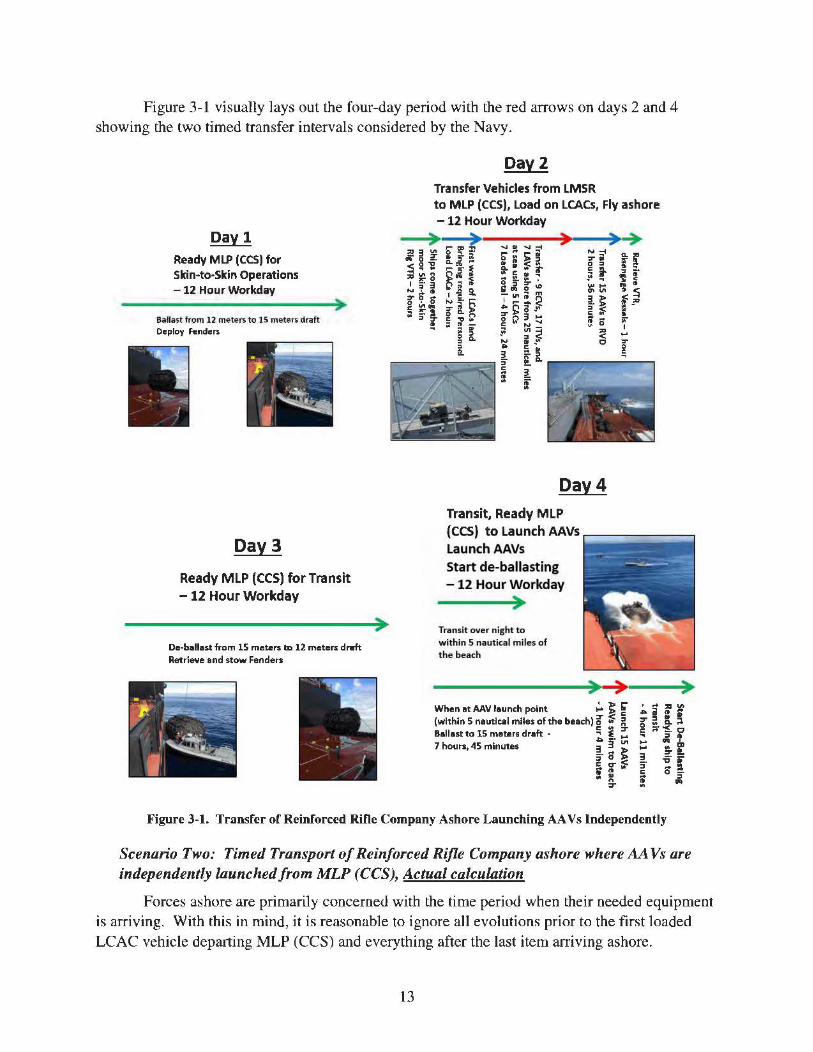
Figure 3-1 visually lays out the four-day period with the red arrows on days 2 and 4 showing the two timed transfer intervals considered by the Navy.
Day 1 Ready MLP (CCS) for Skin-to·Skin Operations - 12 Hour Workday
Ballast from 12 meters to lS meter5 draft Deploy fi!nders
Day3
Ready MLP (CCS) for Transit
- 12 Hour Workday
De·b11ll11st from 15 meters tD 12 meters dnrft Retrieve and stow Fenders
Day2 Transfer Vehicles from LMSR to MLP (CCS), Load on LCACs, Fly ashore - 12 Hour Workday
Transit over night to within 5 nautical miles of the beach
) ) ) When at AAV launch point ;.. ~ ~ (within 5 nautical miles of the beach) ir :;: il Ballast to 15 mebtrs draft • !l i ~ 7 hours, 45 minutes .s:. 3 "' ~- ... J>
::i 0 ):> i; g- ~
= ~ 7
Figure 3-1. Transfer of Reinforced Rifle Company Ashore Launching AA Vs Independently
Scenario Two: Timed Transport of Reinforced Rifle Company ashore where AA Vs are independently launched from MLP (CCS), Actual calculation
Forces ashore are primarily concerned with the time period when their needed equipment is arriving. With this in mind, it is reasonable to ignore all evolutions prior to the first loaded LCAC vehicle departing MLP (CCS) and everything after the last item arriving ashore.
13
Referring back to Table 3-2 and Figure 3-1, this discards Day l, the beginning of Day 2, and the end of Day 4 from timing of the transfer. It does not discard the time. between the two transfer intervals. Therefore, DOT &E estimates that the actual time to transfer the Reinforced Rifle Company equipment ashore is 52 hours and 49 minutes.
Scena1io Three: Timed Transport of Reinforced Rifle Company ashore, Alternate Method -All Vehiclesflown ashore via LCAC
Based on the data available from the MLP (CCS) IOT &E, DOT &E estimates that the time to transfer aJl equipment (including the. AA Vs) via LCAC Joaus alone is 8 hours anu 21 minutes. This scenario eliminates the need to re.position MLP (CCS) and is clearly a more efficient means to transfer a Marine Corps rifle equipment load to shore. This estimate is based on the time data from the five LCAC vehicles used during the IOT&E event combined with the time to transfer the. additional seven LCAC loads of AA Vs. The times for the AAY-loaded LCAC vehicles were determined based on four loads of AA Vs transported 25 nautical miles from MLP (CCS) to a beach at Camp Pendleton during an integrated test event. Table 3-3 shows the sequence of events. Once again from the perspective of forces ashore, the time of interest is from when the first LCAC load leaves MLP (CCS), to when the last load arrives ashore. Therefore, it is reasonable to discard events before and after this. Figure 3-2 illustrates the three-day period. Day 2 violates the 12-hour work day since, in DOT&E's estimate, the events will consume 13 hours. The ship's Master may be able to stagger individual deck force member's work days to cover the event.
Table 3-3. Sequence of Events for Full ~MLP Mission: All Equipment Transferred via LCAC
DAV ACTION TIME
1 Readying MLP (CCS) for skin-to-skin operations Full Work Day
MLP (CCS) moors with the LMSR and rigs the VTR 2 hours
Marine Corps vehicle drivers and traffic directors that arrive on first wave of 2 hours LCACs move the first vehicles from the LMSR to MLP (CCS) and load them on
2 the LCACs
Fly ECVs, ITVs, and LAVs and AAVs ashore via LCAC (14 loads) Estimate - 8 hours 21 min
Retrieve VTR, disengage ships 1 hour
3 De-ballast MLP to 12 meters draft and retrieve fenders Full work day
14
Oayl Ready MLP (CCS) for Skin-to-Skin Operations -12 Hour Workday
Ballast from 12 meters to 15 meters draft Deploy fender~
Transfer Vehicles from LMSR to MLP (CCS), Load on LCACS, Fly ashore - 13 Hour Workday
Day3
Ready MLP (CCS) for Transit - 12 Hour Workday
De-ballast from 15 meters to 12 meters draft Retrieve and stow Fenders
Figure 3-2. Transfer of Entire Reinforce Rifle Company Ashore from 25 nautical miles at Sea
Complete LMSR Offload
Although the ability to support the complete. offload of a full LMSR load was not tested, MLP might be called upon to do so. Based on the test results available, including the timing to land, load, and launch LCAC vehicles, DOT &E was able to estimate the total time necessary to perform such an operation. Six to nine LCAC vehicles would be required depending on the distance from shore; however, properly planned, the most efficient operations would ensure that three are always ready to land on MLP (CCS), right after three loaded-LCACs launch.
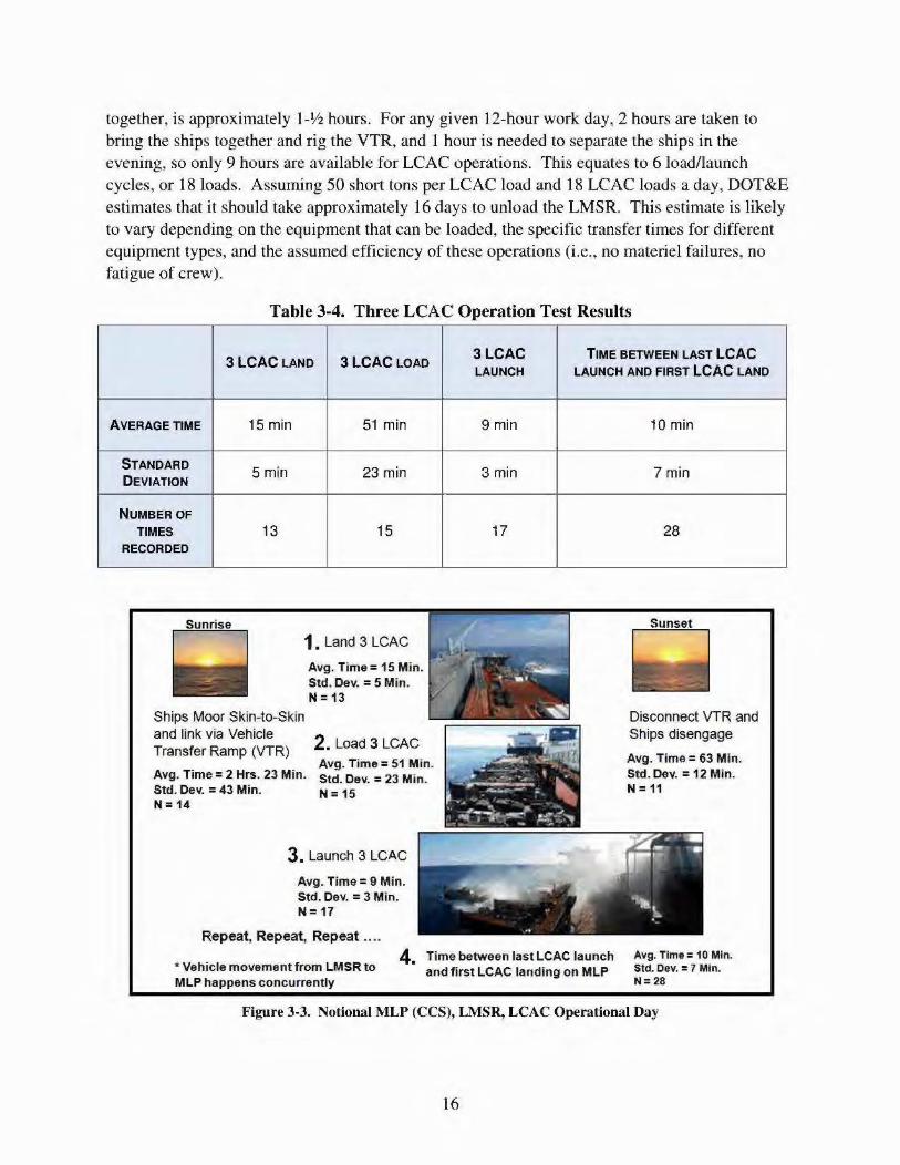
Table 3-4 shows the combined test results from integrated and operational testing, limited to periods when three LCAC vehicles were. operating together. The number of iterations for each activity differs since, for example, an LCAC may be onboard and loaded, two more may arrive and load, and then all three might launch. For the purpose of this table only, the time for the three to launch is recorded. Figure 3-3 shows a pictorial representation of a notional operating day. The test data suggest that the average cycle, three LCACs landing, loading, and launching
15
together, is approximately l-V2 hours. For any given 12-hour work day, 2 hours are taken to bring the ships together and rig the VTR, and 1 hour is needed to separate the ships in the evening, so only 9 hours are available for LCAC operations. This equates to 6 load/launch cycles, or 18 loads. Assuming 50 short tons per LCAC load and 18 LCAC loads a day, DOT&E estimates that it should take approximately 16 days to unload the LMSR. This estimate is likely to vary depending on the equipment that can be loaded, the specific transfer times for different equipment types, and the assumed efficiency of these operations (i.e., no materiel failures, no fatigue of crew).
Table 3-4. Three LCAC Operation Test Results
A VE RAGE TIME
STANDARD DEVIATION
NUMBER OF TIMES
RECORDED
3 LCAC LANO 3LCAC LOAO
15 min
5 rnin
13
51 min
23 min
15
1. Land 3 LCAC
Avg. Time = 15 Min. Std. Dev. = 5 Min. N= 13
Ships Moor Skin-to-Skin and link via Vehicle Transfer Ramp (VTR) 2. Load 3 LCAC
Avg. Time= 51 Min. Avg. Time= 2 Hrs. 23 Min. Std. Dev. = 23 Min. Std. Dev. = 43 Min. N = 15 N= 14
3. Launch 3 LC.AC
Avg. Time= 9 Min. Std. Dev. = 3 Min. N= 17
Repeat, Repeat, Repeat •...
3LCAC LAUNCH
9min
3min
17
TIME BETWEEN LAST LCAC LAUNCH ANO FIRST LCAC LANO
10 min
?min
28
Disconnect VTR and Ships disengage
Avg. Time= 63 Min. Std. Dev.= 12 Min. N = 11
*Vehicle movement from LMSR to MLP happens concurrently
4. Time between last LCAC launch and first LCAC landing on MLP
Avg. Time= 10 Min. Stet. Dev. = 7 Min. N:28
Figure 3-3. Notional MLP (CCS), LMSR, LCAC Operational Day
16
Sea State and Vehicle Transfer Ramp (VTR)
The Navy requires transfers between LMSRs and MLP (CCS) to be conducted in sea states up to mid-Sea State 3. The Navy was successful in demonstrating this capability during JOT &E, but the seas during the testing were not challenging. For purposes of illustration, Figure 3-4 shows USNS Millinocket (JHSV-3) approaching USNS Montford Point (MLP-1) the day of the test, October 29, 2014.
Figure 3-4. USNS Millil10cket (JHSV -3) in Sea Sate 3 Conditions near Camp Pendleton
The seas in Figure 3-4 look very calm, but data from the nearby National Oceanic and Atmospheric Administration buoy indicated a swell from the south with significant wave height of 2V2 feet and a 12'h-second period, which technically meets the Nmth Atlantic Treaty Organization' s (NATO) sea state definition for Sea State 3.
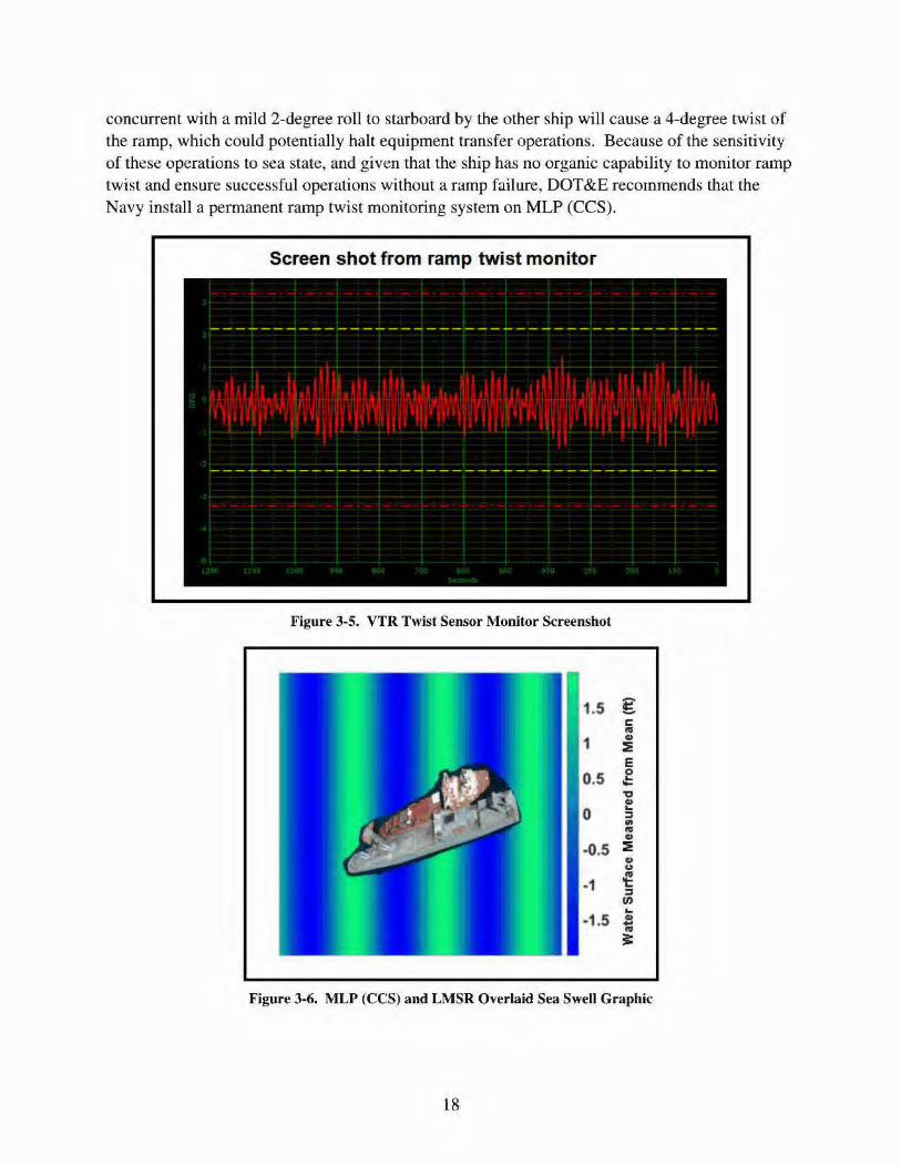
These calm seas have little effect on large ships like MLP (CCS) and LMSRs, but when the two ships are moored together skin-to-skin, great care must be exercised to limit side-to-side rolling since these rolls cause the VTR to twist. During the test period, sensors and indicators were installed to monitor the VTR twist, but these are not standard equipment. A screen shot from the twist monitor is shown in Figure 3-5. Operationally, the ramp twist is kept within 2.2 degrees twist either way from the resting zero position. If ramp twist exceeds 2.2 degrees, vehicle transfers are stopped; if it exceeds 3.3 degrees, the ramp is retrieved and the ships disengage. USNS Bob Hope is 949 feet long and USNS Montford Point is 765 feet long. Figure 3-6 depicts the two ships moored together over a graphic depiction of a 3-foot, l 0-second period westerly swell. The angle at which the two-ship configuration intersects the single swell is adjusted so the bows encounter the wave front at nearly the same time. As seen, the larger USNS Bob hope (LMSR) will interact with three waves while the shorter USNS Montford Point (MLP) sees only two waves. The ship Master must monitor the heading of the two-ship configuration while referring to the VTR twist monitor and adjust to minimize the twist. Even in these relatively calm seas, incon-ect orientation of the ship configuration to the swells can cause the individual ships to mildly roll side-to-si<le. A mild 2-degree roll to port of one ship
17
concurrent with a mild 2-degree roll to starboard by the other ship will cause a 4-degree twist of the ramp, which could potentially halt equipment transfer operations. Because of the sensitivity of these operations to sea state, and given that the ship has no organic capability to monitor ramp twist and ensure successful operations without a ramp failure, DOT &E recommends that the Navy install a permanent ramp twist monitoring system on MLP (CCS).
Screen shot from ramp twist monitor
Figure 3-5. VTR Twist Sensor Monitor Screenshot
1.5 g c t'll
1 GI
:!: E
0.5 0 ¢ 'O GI
0 ... ::I en t'll GI
-0.5 :!: ·41 u
-1 ~ ::I fl)
-1 .5 ... 4> .. t'll
s:
Figure 3-6. MLP (CCS) and LMSR Overlaid Sea Swell Graphic
18
Equipment Transfers between MLP (CCS) and JHSV
JHSV and .MLP (CCS) currently are not capable of conducting equipment transfers at sea. Although MLP is capable of receiving JHSV along its port side and is equipped with appropriate fenders for skin-to-skin operations, equipment transfers failed during the IOT &E period in even relatively calm waters when the JHSV ramp suffered a significant casualty. Figure 3-7 shows JHSV moored skin-to-skin with MLP (CCS). This test was conducted October 29, 2014, at sea, near Camp Pendleton in southern California in Sea State 3 conditions (2'h-foot, 12'h-second swells). The seas in the lee of MLP (CCS), where JHSV was moored, were estimated to be Sea State I to 2. 3 The hydraulic ram used to swing the ramp, port to starboard, tore free from its anchor point on the JHSV transom. The small amount of movement between the ships, even in the very low Sea State 1 to 2 condition, was enough to cause the damage when the truck pinned the foot of the ramp onto the raised vehicle deck of MLP (CCS) as it transited the ramp. Physical strength of the ramp was not compromised; the Marine Corps truck returned to JHSV, but this ended the vehic1e transfer portion of the test. The Navy did not reattempt these operations due to safety concerns. Vehicle transfer operations were successful in earlier developmental testing when MLP (CCS) was at anchor in Sea State 1 conditions inside a harbor; DOT &E does not consider this as operationally realistic.
JHSV-3 moored alongside MLP-1
1st transfer, a truck and trailer, transiting the JHSVramp
)
Figure 3-7. JHSV Alongside MLP (CCS}
Equipment Transfers Between MLP (CCS) and INLS
LMSRs routinely crane equipment to and from INLS, a modular floating causeway system, and refer to the operation as Lift-on, Lift-off or LO/LO operations. On rare occasions,
The lee side is the side of the ship sheltered from the wind.
19
equipment may need to be transferred between MLP (CCS) and INLS. The only way to move equipment between the two is by crane. Figure 3-8 shows that the MLP (CCS) knuckle boom crane has sufficient reach to land items on the deck of an INLS module. The pictured INLS assembly consisted of a powered module, an intermediate module, and a beach module. The safe working load for the knuckle boom crane is 10 metric tons so it can easily move an ECV or an ITV. However, no actual equipment was moved, or was planned to be moved, during the IOT &E. DOT &E concludes that these operations are feasible given the characteristics of the MLP (CCS)'s crane.
Figure 3-8. INLS Alongside MLP (CCS)
Unrefueled Range
MLP (CCS) is required to travel at least 9,500 nautical miles at a sustained transit speed of 15 knots. The Navy conducted a 24-hour mileage test. The conservative estimate based on the data gives an unrefueled range of 12,020 nautical miles.
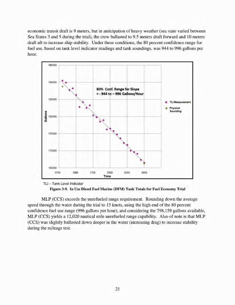
Unrefueled range depends on available fuel and use rate. Available fuel depends on tank size, tank fill level, and tank minimum volume. Assuming that the storage tanks can be filled to 95 percent and depleted to I 0 percent, and that half the volume of the service tanks can be used, the available fuel is 798,159 gallons. Use rate varies primarily with speed through the water and transit draft. Ships, like cars, get different mileage at different speeds, and drag varies with ship draft. The most economic transit speed for MLP (CCS) is 12.5 knots but the unre.fueled range requirement calls for a 15-knot transit. During the 24-hour mileage test, the ship drive shafts were set at 75 revolutions per minute and the ship averaged 15.4 knots through the water. Figure 3-9 show the relevant data from the fue) economy 24-hour trial. MLP (CCS)' s most
20
economic transit draft is 9 meters, but in anticipation of heavy weather (sea state varied between Se.a States 3 and 5 during the trial), the crew ballasted to 9.5 meters draft forward and lO meters draft aft to increase ship stability. Under these conditions, the 80 percent confidence range for fuel use, based on tank level indicator readings and tank soundings, was 944 to 996 gaHons per hour.
195000 .
185000 [
~ I _g 180000 I ftj ~
170000 r
80% Conf. Ranie fOr Slope = -944 to - 996 Gallons/Hour
1~000 ..__~~-'-~~~~~~-'-~~---'-~~~.L-~~-
0700 1200 1700
TU - Tank Level Indicator
2200 Time
0300 0800
+ PhysiQ J Sounding
Figure 3-9. In Use Diesel Fuel Marine (DFM) Tank Totals for Fuel Economy Trial
MLP (CCS) exceeds the unrefueled range requirement. Rounding down the average speed through the water during the trial to l 5 knots, using the high end of the 80 percent confidence fuel use range (996 gallons per hour), and considering the 798, 159 gallons available, MLP (CCS) yieJds a 12,020 nautical mile unrefueled range capability. Also of note is that MLP (CCS) was slightly ballasted down deeper in the water (increasing drag) to increase stability during the mileage test.
21
This page is intentionally left blank.
22
Section Four Operational Suitability
The Mobile Landing Platform with the Core Capability Set (MLP (CCS)) is operationally suitable, having demonstrated an availability of 100 percent. The Mean Time Between Critical Failure requirement is 650 hours. This reliability requirement was demonstrated with zero critical failures in 3,312 operating hours, which gives a one-sided 90 percent confidence Jower bound of 1,438 hours.
Critical Systems Maintenance Review
Although no operational mission failures occurred dur.ing the test, the ship was not without problems that should. be addressed. Testers interviewed senior members of the crew, who highlighted minor and major concerns.
Minor concerns were ones that were a hindrance, but within the ability of the crew to work through. These include:
• Missing technical manuals
• Inadequate parts inventory (resolution of this item is projected to spawn a store room space issue)
• Loose wiring and faulty sensor assembly connections
• Inadequate crew familiarization training
Major concerns follow and may lead to expensive ramifications both in repair dollars and ship downtime.
Accelerated Wear and Tear of Main Diesel Generators (MDG)
Extended periods of low loading of MDGs are causing accelerated wear and tear. The ship has four MDGs, two in the port engine room and two in the starboard engine room. These engines produce all ship power. Each engine turns a generator that powers both the electric propulsion motors and the shjp service electric loads. The ship is an all-electric ship with the exception of distilling units powered by waste heat. The Chief Engineer is concerned that extended periods of low loading on these MDGs will cause accelerated wear and tear. He educated the testers on the normal duty cycle for the base ship, which was designed for crude oil transport. This means that the ship is designed to transit at the most economical speed, and the MDGs are run at mid to heavy loading, where they operate best. As operated now, the ship spends extended periods of time with the diesels lightly loaded. When in Dynamic Positioning (DP) mode, two MDGs are required to be on-line, but each MDG is loaded only to about 20 percent power. Changing the logic to allow a single MDG on-line while in DP mode would increase loading and cause less wear and tear than while under-loaded. This change will add some risk to evolutions since the ship(s) will drift if the on-line MDG trips off-line. Position control wiJI not he reestablished until another MDG is started and brought on-line. While in port, without shore power, or at anchor, at least one MDG must be. on-line to provide ship service
23
electric power; the MDG in this service is also under-loaded. The addition of a separate ship service diesel engine would alleviate these periods of low MDG loading.
Ship Service Power Grooming
Ship service electric power is not adequately groomed, causing damage to sensitive equipment; thus, additional ship service electrical grooming equipment is required. Power loading is best when there is a balance of inductive and capacitive reactive loads. Unfortunately the propulsion motors, by far the largest electric load, are primarily inductive loads, especially at low speed, leading to an imbalance in loading. Harmonic filters are used to groom the electric power used for ship service. The Chief Engineer insists that the installed harmonic filters are inadequate for the job and that additional equipment is required. There is some evidence of hann due to the power loads shifting from inductive to capacitive reactive loading and creating power spikes that are not completely groomed out by the harmonic filters. Three uninterrupted power supplies in the communications module have failed, presumably due to these power spikes. Additional ship service electrical grooming equipment is required.
Mission Deck Lighting
Various mission deck lighting fixtures require attention. There are frequent broken lenses and broken bulbs, the damage caused by water spray from Landing Craft Air Cushion (LCAC) vehicles. LCAC drivers report some visibility issues, especially with the red and green LCAC lane lights during the day. Some light fixtures are experiencing water intrusion and some are difficult to reach for maintenance.
Ballast, De-ballast System
There are problems with the check valves in the ballast tank ventilation system. Due to the nature of heavy-lift ships, the. ballast tank vent piping for most of the ballast tanks has some length of near horizontal piping in it. This is because ventilation piping for the ballast tanks under the extensive mission deck must transit forward or aft to rise up and vent. The mission deck strength and integrity would be compromised if the vent piping went straight up through it These horizontal vent piping runs have check valves to prevent inadvertent filling of the tanks in the case of piping failure or compromise of the piping upstream of the check valve. The vent piping is also designed for high flow venting. The inlet/outlet piping for the ballast tanks is 18-inch diameter piping. The vents are 6-inch diameter piping. The Chief Engineer states that the. vent piping should be 15 to 16 inches in diameter. With 18-inch diameter inlet/outlet piping and. 6-inch diameter vent piping, the airflow speed is about 9 times the water flow speed. This is causing problems with the check valves closing while de-ballasting. Although the check values are designed to stay open with air flow, the high speed of the air flow often causes them to shut during de-ballasting; de-ballasting must be stopped while a crew member connects compressed air hoses to various vent pipe access points to re-open the check valves. This necessitates additional manpower and adds time to de-ballasting operations.
Future corrosion problems are expected due to the mi1d steel piping used for the ballast tank ventilation system. Tank level indicators for the ballast tanks are not accurate below 15 percent and above 85 percent ballast tank levels. The crew routinely fills the ballast tanks until
24
water exits the vent line. Both the Chief Engineer and Master are concerned that in the future, excessive corrosion problems will be caused by the seawater interacting with the mild steel ballast tank ventilation piping.
Vehicle Trans/ er Ramp (VTR)
In addition to the longitudinal ramp twist limitations discussed in Section Three, the ramp has two heavy wear issues. The VTR is a legacy piece of equipment designed to enable off-load of Navy transport ships to a pier via the ship's side. port platforms. These ramps have been modified for the ship-to-ship function by bolting skid plates to the underside of the ramp foot and including a vertical roller than runs in a track on MLP (CCS) to restrict the ramp foot from shifting port or starboard on the MLP (CCS) raised vehicle deck (Figure 4-l). Both the skid plates and the ve11ical roller exhibited significant wear during the test period.
Teflon pads bolted to underside of ramp foot
Vertical roller in a track
Close up
Note wear from sliding of ramp foot back and forth due to relative motion of the ships Vertical roller
in a track
Figure 4-1. Vehicle Transfer Ram1> Foot Details
Towards the end of testing, several of the skid pads partially dislodged from under the ramp foot, and more than once the vertical roller had to be repaired due to wear and tear. Loss of a pad or two would not stop operations, but failure of the vertical roller would. The Chief Engineers thinks that the I Y2-inch diameter pin for the vertical roller is undersized for the loads it withstands. The types of damage the roller suffered during testing support the Chief Engineer's assessment. There is no organic method to reattach foot pads on the ramp if they come completely off; doing so would require shipyard support.
Mooring Line Wear and Tear
Mooring lines experienced heavy wear and tear during skin-to-skin operations and required continual maintenance. The mooring lines were assembled with surge pendants and
25
chaffing gear, for use in holding the two ships together while moored skin-to-skin. The surge pendants accommodate limited movement of the two large ships that otherwise could part (break) the main mooring lines. The chaffing gear protects the mooring lines where the lines go through ship chocks. Only once during testing, with MLP (CCS) moored skin-to-skin with a Large Medium-Speed Roll-on/Roll-off (LMSR), did a mooring line part. This was during the Marine Corps exercise, Pacific Horizon. It took the crew 11 minutes to replace the line and did not interrupt LCAC loading operations so it was not judged as a critical failure. But significant wear and tear of the lines prompted continual mooring line maintenance that must be budgeted for in future operations. Figures 4-2 through 4-4 show examples of mooring line damage.
Figure 4-2. Mooring Line Damage
26
Figure 4-3. Mooring Line Damage
Figure 4-4. Mooring Line Damage
27
This page intentionally left blank.
28
Section Five Cybersecurity
Navy testers from Commander, Operational Test and Evaluation Force (COTF) conducted the local cybersecurity assessment from July 28 through August l, 2014, and the remote evaluation during August 25 - 26, 2014. They found that the Military Sealift Command's (MSC) Afloat Network Operations Center (ANOC) in San Diego, California, provided effective monitoring of all networks in the MSC operated fleet. The ANOC sent email alerts to the ship in near real-time when USNS Montford Point's Host-Based Security System detected suspicious cyber accivities. COTF uncovered two cybersecurity deficiencies that are described in the classified annex of this report.
29
This page is intentionally left blank.
30
Section Six Survivability
Tbe Mobile Landing Platform with the Core Capability Set (MLP (CCS)) is survivable only in protected, benign operating environments. Survivability is a measure of the capability of the MLP' s crew and mission-critical systems to provide a surface interface between the Large, Medium Speed Roll-On Roll-Off (LMSR) prepositioning cargo ships and Joint High Speed Vessels (JHSVs) and the landing craft surface connectors from amphibious ships with well decks. It is also a measure of the capability of the ship to provide protection for the crew to prevent serious injury or death an<l to prevent ship loss. The three components of survivability are susceptibility, vulnerability, and recoverability. Susceptibility is a measure of the capability of the ML P's mission-critical systems and crew to avoid or defeat an attack and is a function of ship design features, operational tactics, signature reduction, countermeasures, and self-defense system effectiveness. If engaged, MLP's capability to withstand the initial threat-induced damage effects, to continue to perform assigned primary warfare missions, and to protect the crew from serious injury or death is measured by vulnerability. Recoverability is a measure of the MLP capability, after initial damage effects, to take emergency action to contain and control damage, prevent ship Joss, minimize personnel casualties, and restore and sustain primary mission capabilities.
Live Fire Test and Evaluation (LFT &E) Critical Issues are survivability-related questions that the LFT &E program is expected to answer. The LFT &E Critical Issues for MLP are:
• What threats are likely to be encountered in combat? (Susceptibility)
• What are the number and type of personnel casualties that will result from likely threat encounters? (Vulnerability)
• Can onhoard personnel evacuate the ship after a threat hit? (Vulnerability and Recoverability)
• What damage to the MLP structure and associated equipment will he caused by likely threat encounters? (Vulnerability)
• How wilJ the Military Sealift Command (MSC) crew restore the ship's capabilities, including mission (mobility, ballast operations, equipment transfer, communications, vital system restoration, flight and boat operations, etc.) and personnel safety (abandon ship and damage control capability, crew triage and medical treatment, etc.), following the damage resulting from the impact and detonation of threat weapons under realistic conditions? (Recoverability)
Susceptibility
MLP (CCS) was designed and buHt to commercial standards. The shlp has no active or passive systems to reduce susceptibility. The ship must rely upon other naval, joint, or combined forces for protection; the effectiveness of these forces to protect MLP was not assessed as part of the LFT &E program. If the ship must operate in a combat environment without protective
31
forces, it may be exposed to a variety of anti-ship weapons, which are listed in the classified annex.
Vulnerability
Although the MLP was designed and built to commercial specifications, these specifications include structural and damage control attributes that offer a degree of protection against threats that may be encountered in a combat environment. Additionally, the ship's size, subdivisions, number of ballast tanks, deballasting capabilities, and its installed fire suppression systems provide a level of protection against secondary fire damage and progressive flooding. For smaJJ damage events confined to a single machinery space, redundancy in the ship's propulsion systems and hull, mechanical and electrical support systems between the port and starboard machinery spaces allows the ship to retain propulsion capability provided the sliding watertight doors are closed. The following elements of the LFT&E program were used to evaluate the ship's vulnerability:
• Surrogate testing - To assess the ability of the ship to continue its mission after weapons damage, a two-part surrogate test series was conducted at the Aberdeen Test Center, Maryland, to obtain data on the fragili ty of commercial shipboard equipment. The test results were used to improve the models used to predict blast damage. Results were also used by system experts to perform analyses of several selected threat shotlines. Detailed results of the testing are discussed in the classified annex.
• Survivability Assessments - The Navy conducted two survivability assessments. The preliminary survivability assessment identified a list of threats likely to be encountered by the MLP during its expected operations, identified threat hit points, and assessed the ship's structure and personnel safety support systems to determine potential vulnerabilities. The study did not look at specific weapon and ship/weapon effect interactions, but instead used a vulnerable area approach where areas of the ship and systems were assessed against broad weapon damage effects. Key vulnerabilities identified in this study are listed in the classified annex. Subsequent to this study, a survivability assessment of the MLP detail design was completed to assess primary and secondary damage from specific threat weapon attacks identified during the preliminary assessment. The assessment identified potential crew casualties and predicted crew damage control and system restoration actions. A Probabi1ity of Kill Given a Hit study was conducted to predict probabilities for loss of mission areas and overall mission from primary damage. Additional information and results are provided in the classified annex.
Recoverability
The primary means of assessing the recoverability of both variants of MLP is the Total Ship Survivability Trial (TSST), which will be accomplished in 2016 on the first Afloat Forward Staging Base variant. The TSST will include two scenarios. The final recoverability assessment uf both variants will be done at that time. Recoverability-related aspects of the CCS variant
32
identified during the preliminary and detail design assessments are provided in the classified annex.
Self Defense
Based on the data obtained during the Initial Operational Test and Evaluation (IOT&E) and with data from the force protection test conducted during the JHSV IOT &E, the capability provided by the 0.50-caliber machine guns is not effective for the ship's force protection. Additionally, MLP (CCS) is built to commercial standards with no active or passive systems to reduce susceptibility. MSC operates MLP (CCS) for the Navy and crews it, and most other proposition ships, with civilian contract mariners. The Navy provides area protection with warships and provides ESTs for close-in self-defense. The security teams, normally 12 members, embark with their own weapons and ammunition. A 12-member team can support 24-hour a day manning of 4 stations. Although the ESTs are manned with well-trained individuals equipped with 0.50-caliber weapons, there is little test data to suggest they provide effective force protection.
Results of early live fire testing and analyses for ship survivability are available in the classified annex to this report. The TSST is scheduled during testing of the follow-on version of MLP equipped as an Afloat Forward Staging Base (MLP (AFSB)) in fiscal year 2016.
MLP (CCS) has weapons mounts, a weapons magazine, and berthing for the security team. There are 12 mounts for 0.50 caliber machine guns. There are two 6-man bunkrooms to berth the 12-person team. A weapons magazine is located port si<le aft for stowage of ammunition and weapons. The EST leader selects which mounts to man. Figure 5-1 shows a possible an-angement.
li~ht Red - l gun coverage Dark Red - 2 gun co.er age
t Im t08P 65 1 UR Hl&S 6S 3 I FRC6P 6!. • 1FR16S (>!;
Figure 5-1. Embarked Security Team Gunner Coverage
Commander, Operational Test an<l Evaluation Force (COTF) and the Marine Corps Operational Test and Evaluation Activity (MCOTEA) conducted a one-day test off the coast of Southern California, finding that the ammunition resupply took too long because of the location of the magazine, and that the magazine was undersized. A Navy security team embarked MLP
33
(CCS) with weapons and ammunition for the test on November 3, 2014. The team successfully performed struclttral tesl fires on all 12 mounts. The team also assessed weapons and ammunition storage and timed an ammunition resupply from the only magazine (port side aft) to the bow. The team determined that resupply of ammunition to the bow takes from 4 to 5 minutes, depending on where team members are stationed. This is twice the tleet standard. The team determined that the magazine was not large enough to can-y a full load-out of EST weapons, ammunition, and supporting equipment.
There are no operational test data available to suggest the ship is adequately defended from a likely small boat attack. An explosive-laden small boat approaching the ship at high speed is a possible threat. Rules of engagement typically allow the gunners to open fire at 100 meters. If the boat is traveling at 20 knots, the gunners have only 5 seconds to disable it. No operational test data support success in this scenario. The 12-person security team can operate 4 of the 12 mounts, so there are several options to achieve 360-degree coverage. The gun mount elevation and angle-stops limit engagement of close-in contacts. Depending on which 4 of the 12 mounts are manned determines how close to the ship the gunners can shoot. The noncoverage over 360 degrees varies for each arrangement of gunners but can extend out to as little as 60 yards or as far out as 200 yards. The ship is most vulnerable when moored skin-to-skin with Navy LMSR cargo ships or a JHSV since the two-ship assembly has httle to no mobility. These other ships, operated by MSC, have the same self-defense limitations.
As stated in Section Two, the limitations of this test were known and accepted. There are complications in testing using live ammunition for civilian-manned vessels so the Navy has proposed use of instrumented firing simulations to resolve the safety concerns. If the Navy is unable to accredit these simulation systems for operational testing, other test methods must be found. When DOT&E approved the Test and Evaluation Master Plan, it was made dear that adequate testing for self-protection must be accomplished for MLP (AFSB). Results should apply to this version of MLP as well.
34
Section Seven Recommendations
To ensure the MLP (CCS) provides as much prepositioning and at-sea transfer of equipment and supplies ashore capability as can reasonably be expected, DOT &E recommends that the Navy:
Operational Effectiveness
• Install permanent Vehicle Transfer Ramp twist sensors and provide a display monitor on the Bridge of Mobile Landing Platform with the Core Capability Set (MLP (CCS)) ships to assist the MLP (CCS) Master during skin-to-skin operations.
• Modify the Joint High Speed Vessel ramp to increase its sea state rating, or develop a new, higher sea state rated ramp, then retest at-sea equipment transfers with MLP (CCS).
Operatio11al Suitability
• Install a separate ship service. diesel generator to minimize periods of under-loading of the Main Diesel Generators.
• Install additional ship service electrical grooming equipment to alleviate ship service power spikes and minimize damage to sensitive electronic equipment.
Cybersecurity
• Address cybersecurity issues identified in the classified annex to this report.
Survivability
• Address live fire issues identified in the classified annex to this report.
• Continue planning for completion of a self-defense test using accredited instrumented firing simulations, or live ammunition and targets, during the Initial Operation Test and Evaluation (IOT&E) of MLP-Afloat Forward Staging Base, USNS Lewis B Puller (MLP-3).