H0296900 Rev C 1. Introduction This document gives instructions for replacing the following items: • Chlorine Generator Face Plate R-Kit • Battery Door R-Kit • DC Wiring Harness R-Kit • AquaPure User Interface R-Kit • AquaPure Power Interface R-Kit • Bezel Support Plate R-Kit • Hardware Kit Before starting this procedure, use the parts list of each kit to identify the parts that are in your kit. If any parts are missing from the kit, please call your local Jandy distributor for assistance. For technical assistance, please contact our Technical Support Department at (800) 822-7933. These instructions must be followed exactly. Read through the instructions completely before starting the procedure. Please save these instructions. WARNING FOR YOUR SAFETY - This product must be installed and serviced by a contractor who is licensed and qualified in pool equipment by the jurisdiction in which the product will be installed where such state or local requirements exist. In the event no such state or local requirement exists, the maintainer must be a professional with sufficient experience in pool equipment installation and maintenance so that all of the instructions in this manual can be followed exactly. Before installing this product, read and follow all warning notices and instructions that accompany this product. Failure to follow warning notices and instructions may result in property damage, personal injury, or death. Improper installation and/or operation will void the warranty. Improper installation and/or operation can create unwanted electrical hazard which can cause serious injury, property damage, or death. Jandy ® AquaLink ® RS PureLink ™ Power Center and Chlorine Generator Control Center Replacement Kit These instructions are to be used with the following Jandy Replacement Kits: R0447300-- Battery Door, PureLink Power Center, R-kit R0447500-- Wiring Harness, PureLink Power Center & Chlorine Generator Control Center, R-Kit R0467400-- AquaPure ® User Interface Assembly, PureLink ™ Power Center & Chlorine Generator Control Center, R-Kit R0467600-- AquaPure Power Interface Assembly, PureLink Power Center & Chlorine Generator Control Center, R-Kit R0467700-- AquaLink RS Bezel Plate Kit, PureLink Power Center, R-Kit R0467800-- Hardware, PureLink Power Center & Chlorine Generator Control Center, R-Kit R0503300-- Battery Door, Chlorine Generator Control Center, R-Kit R0503400-- Face Plate, Chlorine Generator Control Center, R-Kit R0562100-- AquaLink RS Bezel Plate Kit, PureLink Power Center, 08/09 Models or Later, R-Kit WARNING If the information in these instructions is not followed exactly, an electrical fire or shock hazard may result causing property damage, personal injury or death.
Transcript
H02
9690
0 R
ev C
1. Introduction
This document gives instructions for replacing the following items:
• Chlorine Generator Face Plate R-Kit• Battery Door R-Kit• DC Wiring Harness R-Kit• AquaPure User Interface R-Kit• AquaPure Power Interface R-Kit• Bezel Support Plate R-Kit• Hardware Kit
Before starting this procedure, use the parts list of each kit to identify the parts that are in your kit. If any parts are missing from the kit, please call your local Jandy distributor for assistance.
For technical assistance, please contact our Technical Support Department at (800) 822-7933.
These instructions must be followed exactly. Read through the instructions completely before starting the procedure. Please save these instructions.
WARNING FOR YOUR SAFETY - This product must be installed and serviced by a contractor who is licensed and qualified in pool equipment by the jurisdiction in which the product will be installed where such state or local requirements exist. In the event no such state or local requirement exists, the maintainer must be a professional with sufficient experience in pool equipment installation and maintenance so that all of the instructions in this manual can be followed exactly. Before installing this product, read and follow all warning notices and instructions that accompany this product. Failure to follow warning notices and instructions may result in property damage, personal injury, or death. Improper installation and/or operation will void the warranty.Improper installation and/or operation can create unwanted electrical hazard which can cause serious injury, property damage, or death.
WARNING If the information in these instructions is not followed exactly, an electrical fire or shock hazard may result causing property damage, personal injury or death.
Page 2 Zodiac® | Jandy® AquaLink® RS PureLink™ Power Center and Chlorine Generator Control Center Replacement Kit
Dwg Kit#Description1 R0503300 Battery Door2 R0447500 Wiring Harness3 R0467400 AquaPure User Interface4 R0467600 AquaPure Power Interface 5 R0503400 Face Plate6 R0467800 Hardware Kit (All screws shown)
Page 3Jandy® AquaLink® RS PureLink™ Power Center and Chlorine Generator Control Center Replacement Kit | Zodiac®
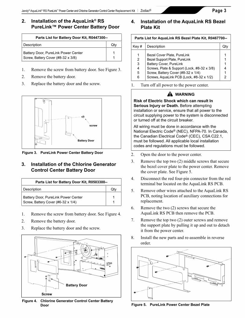
4. InstallationoftheAquaLinkRSBezelPlateKit
PartsListforAquaLinkRSBezelPlateKit,R0467700--
Key # Description Qty
123456
Bezel Cover Plate, PureLinkBezel Support Plate, PureLinkBattery Cover, PureLinkScrews, Plate & Support (Lock, #8-32 x 3/8)Screw, Battery Cover (#8-32 x 1/4)Screws, AquaLink PCB (Lock, #8-32 x 1/2)
111412
1. Turn off all power to the power center.
WARNINGRiskofElectricShockwhichcanresultInSeriousInjuryorDeath.Before attempting installation or service, ensure that all power to the circuit supplying power to the system is disconnected or turned off at the circuit breaker. All wiring must be done in accordance with the National Electric Code® (NEC), NFPA-70. In Canada, the Canadian Electrical Code® (CEC), CSA C22.1, must be followed. All applicable local installation codes and regulations must be followed.
2. Open the door to the power center.3. Remove the top two (2) middle screws that secure
the bezel cover plate to the power center. Remove the cover plate. See Figure 5.
4. Disconnect the red four-pin connector from the red terminal bar located on the AquaLink RS PCB.
5. Remove other wires attached to the AquaLink RS PCB, noting location of auxiliary connections for replacement.
6. Remove the two (2) screws that secure the AquaLink RS PCB then remove the PCB.
7. Remove the top two (2) outer screws and remove the support plate by pulling it up and out to detach it from the power center.
8. Install the new parts and re-assemble in reverse order.
WARNINGRiskofElectricShockwhichcanresultInSeriousInjuryorDeath.Before attempting installation or service, ensure that all power to the circuit supplying power to the system is disconnected or turned off at the circuit breaker. All wiring must be done in accordance with the National Electric Code® (NEC), NFPA-70. In Canada, the Canadian Electrical Code® (CEC), CSA C22.1, must be followed. All applicable local installation codes and regulations must be followed.
2. Open the door to the power center.3. Remove the top two (2) middle screws that secure
the cover plate to the power center. Remove the cover plate.
4. Remove the four (4) screws the secure the user interface assembly to the bezel. Remove the user interface.
5. Disconnect the ribbon cable (16-pin J1 connector) from the back of the user interface board. See Figure 7.
6. Install the new user interface assembly and re-assemble in reverse order.
Bezel Cover Plate, PureLink (Larger)Bezel Support Plate, PureLink (Larger)Battery Cover, PureLinkScrews, Plate & Support (Lock, #8-32 x 3/8)Screw, Battery Cover (#8-32 x 1/4)Screws, AquaLink PCB (Lock, #8-32 x 1/2)
111412
1. Turn off all power to the power center.
WARNINGRiskofElectricShockwhichcanresultInSeriousInjuryorDeath.Before attempting installation or service, ensure that all power to the circuit supplying power to the system is disconnected or turned off at the circuit breaker. All wiring must be done in accordance with the National Electric Code® (NEC), NFPA-70. In Canada, the Canadian Electrical Code® (CEC), CSA C22.1, must be followed. All applicable local installation codes and regulations must be followed.
2. Open the door to the power center.3. Remove the top two (2) middle screws that secure
the bezel cover plate to the power center. Remove the cover plate. See Figure 6.
4. Disconnect the red four-pin connector from the red terminal bar located on the AquaLink RS PCB.
5. Remove other wires attached to the AquaLink RS PCB, noting location of auxiliary connections for replacement.
6. Remove the two (2) screws that secure the AquaLink RS PCB then remove the PCB.
7. Remove the top two (2) outer screws and remove the support plate by pulling it up and out to detach it from the power center.
8. Install the new parts and re-assemble in reverse order.
WARNINGRiskofElectricShockwhichcanresultInSeriousInjuryorDeath.Before attempting installation or service, ensure that all power to the circuit supplying power to the system is disconnected or turned off at the circuit breaker. All wiring must be done in accordance with the National Electric Code® (NEC), NFPA-70. In Canada, the Canadian Electrical Code® (CEC), CSA C22.1, must be followed. All applicable local installation codes and regulations must be followed.
2. Open the door to the control center.3. Remove the top two (2) screws that secure the
cover plate to the control center. Remove the cover plate. See Figure 8.
4. Remove the four (4) screws that secure the user interface assembly to the mounting bracket. Remove the user interface.
5. Disconnect the ribbon cable (16-pin J1 connector) from the back of the user interface board. See Figure 8.
6. Install the new user interface assembly and re-assemble in reverse order.
AquaPure Power Interface Board, PureLink Power Center
1
The AquaPure power interface board is configured as Model AP1400 by factory default. However, the power interface board can be configured as Model AP700.
To configure the board as Model AP700, use a cutting plier to cut the JL1 jumper as shown in Figure 9.
Figure9. AquaPure®PowerInterfaceBoard
Cut JL1 Jumper toconfigure board asModel AP700
AquaPure Power Interface Boardand Heat Sink L-Bracket
1. Turn off all power to the power center.
WARNINGRiskofElectricShockwhichcanresultInSeriousInjuryorDeath.Before attempting installation or service, ensure that all power to the circuit supplying power to the system is disconnected or turned off at the circuit breaker. All wiring must be done in accordance with the National Electric Code® (NEC), NFPA-70. In Canada, the Canadian Electrical Code® (CEC), CSA C22.1, must be followed. All applicable local installation codes and regulations must be followed.
Page 6 Zodiac® | Jandy® AquaLink® RS PureLink™ Power Center and Chlorine Generator Control Center Replacement Kit
The AquaPure power interface board is configured as Model AP1400 by factory default. However, the power interface board can be configured as Model AP700.
To configure the board as Model AP700, use a cutting plier to cut the JL1 jumper as shown in Figure 11.
Figure11.AquaPure®PowerInterfaceBoard
Cut JL1 Jumper toconfigure board asModel AP700
AquaPure Power Interface Boardand Heat Sink L-Bracket
Page 7Jandy® AquaLink® RS PureLink™ Power Center and Chlorine Generator Control Center Replacement Kit | Zodiac®
1. Turn off all power to the control center.
WARNINGRiskofElectricShockwhichcanresultInSeriousInjuryorDeath.Before attempting installation or service, ensure that all power to the circuit supplying power to the system is disconnected or turned off at the circuit breaker. All wiring must be done in accordance with the National Electric Code® (NEC), NFPA-70. In Canada, the Canadian Electrical Code® (CEC), CSA C22.1, must be followed. All applicable local installation codes and regulations must be followed.
2. Open the door of the control center.3. Remove the top two (2) screws that secure the
cover plate to the control center. Remove the cover plate. See Figure 4.
4. Disconnect the cable from the power interface board that leads to the user interface assembly.
5. Disconnect the cable from the power interface board that leads to the AquaPure sensor.
6. Disconnect the cable from the power interface board that leads to the transformer.
7. Disconnect the DC wiring harness from the power interface board.
8. Remove the two (2) center screws that secure the power interface board to the control center can. Remove the power interface board.
9. Install the new power interface board and reconnect cables and connectors in reverse order.
Wiring Harness, PureLink Power Interface DC Cord 1
1. Turn off all power to the power center.
WARNINGRiskofElectricShockwhichcanresultInSeriousInjuryorDeath.Before attempting installation or service, ensure that all power to the circuit supplying power to the system is disconnected or turned off at the circuit breaker. All wiring must be done in accordance with the National Electric Code® (NEC), NFPA-70. In Canada, the Canadian Electrical Code® (CEC), CSA C22.1, must be followed. All applicable local installation codes and regulations must be followed.
2. Open the door of the power center.3. Remove the cover to access the power interface
board. See Figures 1, 2 and 7.4. Disconnect the DC wiring harness from the power
interface board. See Figure 10.5. For the PureLink power center, remove the lower
dead panel.6. Carefully disconnect and remove the old harness.
See Figure 10.7. Install the new harness and route cable as shown,
making sure all connections are tight and secure.
Figure12.PureLinkPowerCenterScrewKit
2
1
5
4
3
Zodiac Pool Systems, Inc. 2620 Commerce Way, Vista, CA 92081 1.800.822.7933 | www.ZodiacPoolSystems.com
ZODIAC® is a registered trademark of Zodiac International, S.A.S.U., used under license.All trademarks referenced herein are the property of their respective owners.
Screws, User Interface (#6 x 3/8 Phillips)Screws, Power Interface (Lock, #8-32 x 3/8)Screws, Cover & Support (Lock, #8-32 x 3/8)Screws, AquaLink® PCB (Lock, #8-32 x 1/2)Screws, Battery Door (#6-32 x 1/4 Phillips)
4 2421
1. Turn off all power to the power/control center.
WARNINGRiskofElectricShockwhichcanresultInSeriousInjuryorDeath.Before attempting installation or service, ensure that all power to the circuit supplying power to the system is disconnected or turned off at the circuit breaker. All wiring must be done in accordance with the National Electric Code® (NEC), NFPA-70. In Canada, the Canadian Electrical Code® (CEC), CSA C22.1, must be followed. All applicable local installation codes and regulations must be followed.