28
January 2020 Pre-insulated Pipe Systems

January 2020
Pre-insulated Pipe Systems

2
HEATING AustroPUR single and twin ...................................................................................................................................................................... 4 - 5
SANITARY / POTABLE WATER AustroPUR Sani - single and double ............................................................................................. 6 - 7
HEATING & SANITARY AustroPEX Quad Pipe ............................................................................................................................................................ 8
HEAT PUMP AustroPEX WPP & WPE pipes ............................................................................................................................................................... 9
COLD AND COOLING WATER AustroPEX CW ........................................................................................................................................................ 10
AXIAL PRESS FITTINGS .................................................................................................................................................................................................... 11 - 13
COMPRESSION FITTINGS .............................................................................................................................................................................................. 14 - 16
ACCESSORIES ........................................................................................................................................................................................................................ 17 - 20
LONG TIME BEHAVIOUR ............................................................................................................................................................................................................ 21
INSTALLATION GUIDELINES .................................................................................................................................................................................................... 23
PRESSURE LOSS ................................................................................................................................................................................................................. 24 - 25
PRESSURE TEST ............................................................................................................................................................................................................................. 26
HEAT LOSS ........................................................................................................................................................................................................................................... 27
Contents
3
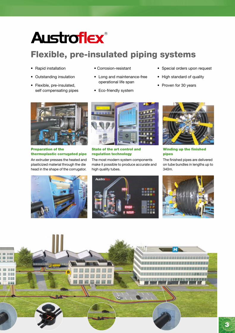
Flexible, pre-insulated piping systems• Rapid installation
• Outstanding insulation
• Flexible, pre-insulated, self compensating pipes
• Corrosion-resistant
• Long and maintenance-free operational life span
• Eco-friendly system
• Special orders upon request
• High standard of quality
• Proven for 30 years
State of the art control and regulation technology
The most modern system components make it possible to produce accurate and high quality tubes.
Winding up the finished pipes
The finished pipes are delivered on tube bundles in lengths up to 340m.
Preparation of the thermoplastic corrugated pipe
An extruder presses the heated and plasticized material through the die head in the shape of the corrugator.

4 MAINCOR
HEATING
AustroPUR single and twinFlexible pre-insulated, self-compensating pipe, suitable for use as a district heating pipe for central heating systems. Corrosion-resistant transport pipe in cross-linked PE-Xa in accordance with DIN 16892/16893, with red oxygen diffusion barrier EVOH in accordance with DIN 4726 is embedded in an elastic, CFC-free foam insulation made from polyurethane. The peripherality made from cross-linked PE-X with closed microcellular structure together with the corrugated outside casing in PE-HD ensures high-great protection to the piping system.
• Max operating pressure: 6,6 bar at +95 °C
• Max fluid temperature: +95 °C
• PE-Xa pipes: SDR 11
• At 250mm outer casing the delivery form is in 12m bars
• Specific dimension on request
AustroPURsingle
PE-Xa(O.D. x s)
PE-Xa(I.D.)
Outer Casing(O.D.)
WeightBending radius
Coillength
Art. No. mm DN mm kg/m m m
114APE125125 25x2,3 20 125 1,26 0,40 340
114APE125132 32x2,9 25 125 1,35 0,50 340
114APE125140 40x3,7 32 125 1,91 0,50 340
114APE125150 50x4,6 40 125 2,10 0,60 340
114APE145163 63x5,8 50 145 3,25 0,70 240
114APE145175 75x6,8 65 145 3,59 0,80 240
114APE175190 90x8,2 75 175 4,47 1,00 150
114APE200110 110x10,0 90 200 5,29 1,10 100
114APE240125 125x11,4 100 240 7,57 1,30 85
114APE250160* 160x14,6 130 250 15,47 –* –*
*12m bars
Outer casing+ transport pipe
Rubber end capsingle
Heat shrink end cap single
Restraining clampsfor single
Adaptor with male thread
Typ Art. No. Art. No. Art. No. Art. No.
A125-1x25 116ENS125025 116ENO125020 116AFS125 116WHA025034
A125-1x32 116ENS125032 116ENO125040 116AFS132 116WHA032001
A125-1x40 116ENS125040 116ENO125040 116AFS140 116WHA040054
A125-1x50 116ENS125050 116ENO145050 116AFS150 116WHA050064
A145-1x63 116ENS145063 116ENO145070 116AFS163 116WHA063002
A145-1x75 116ENS145075 116ENO200080 116AFS175 116WHA075212
A175-1x90 116ENS175090 116ENO200080 116AFS190 116WHA090003
A200-1x110 116ENS200110 116ENO200090 116AFS199 116WHA110004
A240-1x125 116ENO250100 116AFS200 116WHA125004
A250-1x160 116ENO250110 116WHA160005
Further fitting information can be found on page 11-16. The installation of restraining clamps is required to absorb the possible effects of thermal expansions / shrinkage of the PE-Xa transport pipes.sport pipes.
AustroPUR single
AustroPUR single and twin (heating 6 bar)

5www.maincor.co.uk
AustroPUR twin
Wall feed-throughfor pressurised water
Outer Casing(O.D.)
Sealing range /Core drilling
Art. No. mm mm
116HED125200 125 198 - 202
116HED145200145
198 - 202
116HED145250 248 - 252
116HED175250 175 248 - 252
116HED200300 200 298 - 302
116HED240350 240 348 - 352
116HED250300 250 298 - 302
Wall feed-throughfor non-pressurised water
Outer Casing(O.D.)
Wall feedthrough pipe (O.D.) Length
Art. No. mm mm mm
116HEN125 125 160 500
116HEN145 145 175 500
116HEN175 175 235 500
116HEN200 200 250 500
116HEN250 250 + 240 290 500
HEATING
AustroPURtwin
PE-Xa(O.D. x s)
PE-Xa(I.D.)
Outer Casing(O.D.)
WeightBending radius
Coillength
Art. No. mm DN mm kg/m m m
114APE125225 2-25x2,3 20 125 1.6 0,50 340
114APE125232 2-32x2,9 25 125 1.8 0,60 340
114APE145240 2-40x3,7 32 175 2.4 0,80 240
114APE175250 2-50x4,6 40 200 3.6 1,10 150
114APE200263 2-63x5,8 50 200 4.8 1,20 100
114APE240275 2-75x6,8 65 240 6.9 1,40 85
AustroPUR twin
Outer casing+ transport pipe
Rubber end captwin
Heat shrink end cap twin
Restraining clampsfor twin
Adaptor with male thread
Typ Art. No. Art. No. Art. No. Art. No.
A125-2x25 116ENS125225 116ENO145230 116AFS225 116WHA025034
A125-2x32 116ENS125232 116ENO145230 116AFS232 116WHA032001
A145-2x40 116ENS145240 116ENO200260 116AFS240 116WHA040054
A175-2x50 116ENS175250 116ENO200270 116AFS250 116WHA050064
A200-2x63 116ENS200263 116ENO200290 116AFS263 116WHA063002
A240-2x75 N/A 116ENO240210 116AFS275 116WHA075212
Further fitting information can be found on page 11-16. The installation of restraining clamps is required to absorb the possible effects of thermal expansions / shrinkage of the PE-Xa transport pipes.
AustroPUR twin

6 MAINCOR
POTABLE WATER
AustroPUR Sani single & double (10 bar)Flexible pre-insulated and self-compensating double pipe primarily intended for the distribution of sanitary hot water, warm potable and thermal water.
Corrosion-resistant medium pipe made of cross-linked PE-Xa according to DIN 16892/16893, embedded in an elastic and CFC-free foam insulation made of polyurethane.
The peripheral layer of cross-linked PEX with a closed microcellular structure, together with the corrugated outer shell made of PE-HD, ensures maximum flexibility and optimum protection of insulation and carrier pipe.
• Max operating pressure: 10 bar at +95 °C
• Max operating temperature: +95 °C
• PE-Xa pipes: SDR 7.4
• Specific dimension on request
AustroPURsingle
PE-Xa(O.D. x s)
PE-Xa(I.D.)
Outer Casing(O.D.)
WeightBending radius
Coillength
Art. No. mm DN mm kg/m m m
114APR125125 25x3,5 18 125 1,5 0,40 260
114APR125132 32x4,4 25 125 1,6 0,50 340
114APR125140 40x5,5 32 125 1,8 0,50 340
114APR145150 50x6,9 40 145 2,10 0,60 240
114APR145163 63x8,6 50 145 2,8 0,70 240
Outer casing+ transport pipe
Rubber end capsingle
Heat shrink end cap single
Restraining clampsfor single
Adaptor with male thread
Typ Art. No. Art. No. Art. No. Art. No.
A125-1x25 116ENS125025 116ENO125020 116AFS125 116WSA025034
A125-1x32 116ENS125032 116ENO125040 116AFS132 116WSA032001
A125-1x40 116ENS125040 116ENO125050 116AFS140 116WSA040054
A145-1x50 116ENS145050 116ENO145050 116AFS150 116WSA050064
A145-1x63 116ENS145063 116ENO145070 116AFS163 116WSA063002
Further fitting information can be found on page 11-16. The installation of restraining clamps is required to absorb the possible effects of thermal expansions / shrinkage of the PE-Xa transport pipes.
AustroPUR Sani single
AustroPUR Sani single (potable water 10 bar)

7www.maincor.co.uk
POTABLE WATER
Wall feed-throughfor pressurised water
Outer Casing(O.D.)
Sealing range /Core drilling
Art. No. mm mm
116HED125200 125 198 - 202
116HED145200145
198 - 202
116HED145250 248 - 252
Wall feed-throughfor non-pressurised water
Outer Casing(O.D.)
Wall feedthrough pipe (O.D.) Length
Art. No. mm mm mm
116HEN125 125 160 500
116HEN145 145 175 500
AustroPURdouble
PE-Xa(O.D. x s)
PE-Xa(I.D.)
Outer Casing(O.D.)
WeightBending radius
Coillength
Art. No. mm DN mm kg/m m m
114APR12522625 x 3,5
+20 x 2,820 15
125 1,6 0,50 260
114APR14523432x 4,4
+20 x 2,825 15
145 2,1 0,60 240
114APR14524140 x 5,5
+25 x 3,53220
145 2,3 0,70 240
114APR14525250 x 6,9
+32 x 4,44025
145 2,8 0,70 240
AustroPUR Sani double (potable water 10 bar)
Outer casing+ transport pipe
Rubber end capdouble
Heat shrink end cap double
Restraining clampsfor double
Adaptor with male thread
Typ Art. No. Art. No. Art. No. Art. No.
A125- 25 + 20
116ENS125224 116ENO125240 116AFS226116WSA025034 116WSA020034
A145- 32 + 20
116ENS145234 116ENO145240 116AFS234116WSA032001 116WSA020034
A145- 40 + 25
116ENS145241 116ENO145260 116AFS241116WSA040054 116WSA025034
A145- 50 + 32
116ENS145252 116ENO200270 116AFS252116WSA050064 116WSA032001
Further fitting information can be found on page 11-16. The installation of restraining clamps is required to absorb the possible effects of thermal expansions / shrinkage of the PE-Xa transport pipes.
AustroPUR Sani-double

8 MAINCOR
HEATING & SANITARY
Quad PipeThe quad combines 4 pipes, two for use with flow and return heating pipework, one for use with a hot water flow and second hot water pipe for the secondary circulation loop.
The internal corrosion-resistant pipes are cross-linked PE-Xa (in accordance with DIN 16892/16893), with a red oxygen barrier included for the heating pipes (EVOH barrier in accordance with DIN 7426).
The internal foam that supports and insulates the pipework is a CFC-free foam made from cross-linked PE-X with closed microcellular structure and has a minimal water absorption capacity of <1% (in accordance with DIN 53428). In the centre of the 4 pipes is a PE-X centre piece which guarantees an effective separation between flow, return, hot water and circulation pipes. A corrugated outer casing in PE-HD ensures protection to the piping system whilst allowing maximum flexibility.
The quad pipe system offers the following benefits:
• 4 pipes in 1 – Saves money on materials
• Reduce trench size which reduces excavation costs
• One pipe to lay thus reducing labour costs
• Internal connections in one position
• Flexible solution offers a fast installation
• Pipe cut to size (minimum length 10m, maximum length 100m)
• No specialist tools required for installation
AustroPEXCombi
PE-Xa(O.D. x s)
PE-Xa(di)
Outer Casing(O.D.)
WeightBending radius
Coillength
Art. No. mm DN mm kg/m m m
2- 25x2,3 20
115APX145418 1- 25x3,5 20 145 1,8 0,80 100
1- 20x2,8 15
2- 32x2,9 25
115APX175404 1- 25x3,5 20 175 3,0 0,80 100
1- 20x2,8 15
2- 32x2,9 25
115APX175436 1- 32x4,4 25 175 2,7 0,80 100
1- 20x2,8 15
Outer casing+ transport pipe
Rubber end capsingle
Adaptor with male thread
Typ Art. No. Art. No. Number
116WHA025034 x2
A145-3/25 + 1/20 116ENS145426 116WSA025034 x1
116WSA020034 x1
116WHA032001 x2
A175-2/32 + 1/25 + 1/20 116ENS175435 116WSA025034 x1
116WSA020034 x1
116WHA032001 x2
A175-3/32 + 1/20 116ENS175436 116WSA032001 x1
116WSA020034 x1

9www.maincor.co.uk
AustroPEX WPP heat pump pipesFlexible pre-insulated and self-compensating cable with two heating pipes and two empty conduits. Corrosion resistant transport pipe in cross-linked PE-Xa in accordance with DIN 16892/16893, with red oxygen diffusion barrier EVOH in accordance with DIN 4726.
The empty conduit can be used to feed cables to the heat pump.
Thermal, elastic, CFC-free foam insulation made from cross-linked PE-X with closed microcellular structure. Minimal water absorption capacity of < 1% in accordance with DIN 53428. Insulating PE-X centrepiece guarantees an effective separation of flow and return pipes. The corrugated outside casing in PE-HD ensures high-great protection to the piping system.
• Standard full coil length: 100m
• Non stock product
HEAT PUMP
AustroPEX WPPPE-Xa
(O.D. x s)PE-Xa
(di)Outer casing
(O.D.)Conduit(O.D.)
Conduit(O.D.)
Bendingradius
Coillength
Art. No. mm DN mm mm mm m m
118WPP125432 2- 32x2,9 25 125 Ø 32 Ø 25 0,50 100
118WPP145440 2- 40x3,7 32 145 Ø 32 Ø 25 0,60 100
AustroPEX WPPStainless Steel
corrugated pipeOuter casing
(O.D.)Conduit(O.D.)
Conduit(O.D.)
Bendingradius
Coillength
Art. No. mm mm mm mm m m
118WPE125425 2 x DN 25 125 Ø 32 Ø 25 0,50 100
118WPE145432 2 x DN 32 145 Ø 32 Ø 25 0,60 100
118WPE175440 2 x DN 25 175 Ø 32 Ø 25 0,80 100
AustroPEX WPE heat pump pipesFlexible pre-insulated and self-compensating cable with two heating pipes and two empty conduits.Flexible transport pipe made of stainless steel 1.4404 (AISI 316L). The empty conduits can be used to feed cables to the heat pump.Thermal, elastic, CFC-free foam insulation made from cross-linked PE-X with closed microcellular structure. Minimal water absorption capacity of < 1% in accordance with DIN 53428. Insulating PE-X centrepiece guarantees an effective separation of flow and return pipes.The corrugated outside casing in PE-HD ensures high-great protection to the piping system.
• Standard full coil length: 100m
• Non stock product
10 MAINCOR
COLD AND COOLING WATER
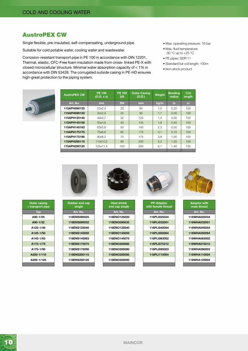
AustroPEX CWSingle flexible, pre-insulated, self-compensating, underground pipe.
Suitable for cold potable water, cooling water and wastewater.
Corrosion-resistant transport pipe in PE 100 in accordance with DIN 12201. Thermal, elastic, CFC-Free foam insulation made from cross- linked PE-X with closed microcellular structure. Minimal water absorption capacity of < 1% in accordance with DIN 53428. The corrugated outside casing in PE-HD ensures high-great protection to the piping system.
• Max. operating pressure: 16 bar
• Max. fluid temperature: -30 °C up to +25 °C
• PE pipes: SDR 11
• Standard full coil length: 100m
• Non stock product
AustroPEX CWPE 100
(O.D. x s)PE 100
(di)Outer Casing
(O.D.)Weight
Bendingradius
Coillength
Art. No. mm DN mm kg/m m m
115APH090125 25x2,3 20 90 1,0 0,25 100
115APH090132 32x2,9 25 90 1,1 0,30 100
115APH125140 40x3,7 32 125 1,4 0,35 100
115APH145150 50x4,6 40 145 1,8 0,40 100
115APH145163 63x5,8 50 145 2,3 0,55 100
115APH175175 75x6,8 65 175 3,1 0,70 100
115APH175190 90x8,2 75 175 3,8 1,00 100
115APH200110 110x10,0 90 200 5,2 1,20 100
115APH200125 125x11,4 100 200 6,1 1,40 100
Outer casing+ transport pipe
Rubber end capsingle
Heat shrink end cap single
PP-Adaptorwith female thread
Adaptor with male thread
Typ Art. No. Art. No. Art. No. Art. No.
A90-1/25 116ENS090025 116ENO125020 116PLI025034 116WHA025034
A90-1/32 116ENS090032 116ENO090030 116PLI032001 116WHA032001
A125-1/40 116ENS125040 116ENO125040 116PLI040054 116WHA040054
A145-1/50 116ENS145050 116ENO145050 116PLI050064 116WHA050064
A145-1/63 116ENS145063 116ENO145070 116PLI063002 116WHA063002
A175-1/75 116ENS175075 116ENO200080 116PLI075212 116WHA075212
A175-1/90 116ENS175090 116ENO200080 116PLI090003 116WHA090003
A200-1/110 116ENS200110 116ENO200090 116PLI110004 116WHA110004
A200-1/125 116ENS200125 116ENO200090 116WHA125004

11www.maincor.co.uk
AXIAL PRESS FITTINGS
Axial Press Fittings
As an alternative to compression fittings, Maincor offer a full range of axial press fittings for joining Pipe and making building connections.
The fittings are made of CW617N-Dw brass and require tooling to first expand the pipe and then slide the metal retaining sleeve onto the pipe and fitting.
Tooling can be hired via various National tool hire companies or alternatively, for regular users, Maincor can supply the tooling. Fittings are available for 6 bar Pipes and a compression sleeve is required for each axial press connection onto the PEX pipe.
A full range of tee’s, couplers and elbows are also available for AustroPUR Heating 6 bar.
Compression Sleeve for Axial Press Fittings (For PUR Heating 6 bar)
PEX to Male Thread Axial Press Fittings (For PUR Heating 6 bar)
DescriptionPack
Quantity
25mm Compression Sleeve 1
32mm Compression Sleeve 1
40mm Compression Sleeve 1
50mm Compression Sleeve 1
63mm Compression Sleeve 1
75mm Compression Sleeve 1
90mm Compression Sleeve 1
110mm Compression Sleeve 1
DescriptionPack
Quantity
25mm x 2.5mm PEX Axial Press Male thread ¾“ 1
25mm x 2.5mm PEX Axial Press Male thread 1“ 1
32mm x 2.9mm PEX Axial Press Male thread 1“ 1
40mm x 3.7mm PEX Axial Press Male thread 1¼“ 1
50mm x 4.6mm PEX Axial Press Male thread 1¼“ 1
50mm x 4.6mm PEX Axial Press Male thread 1½” 1
63mm x 5.8mm PEX Axial Press Male thread 2” 1
75mm x 6.9mm PEX Axial Press Male thread 2½” 1
90mm x 8.2mm PEX Axial Press Male thread 3” 1
110mm x 10mm PEX Axial Press Male thread 4” 1
12 MAINCOR
Axial Press Fittings - Guidance On Use Freezing Conditions
Water supply systems must be installed in a location and/ or with sufficient insulation to ensure that they do not freeze at any time. Freezing of a water supply line can damage the pipe, fittings, valves, parts, and cause water damage.
Corrosion
The internal PEX pipes are widened by the expanding tool prior to inserting the fitting. The average flow of the fittings is adapted to the average flow of the pipe which results in a constant flow, a reduced noise emission and a better erosion resistance.
Corrosion can damage brass plumbing fittings, which should therefore be protected with suitable material if they come into contact with such materials as masonry, rendering, or cement.
Non-Detachable Joint
Once the fitting is made, the axial press fitting is non-demountable.
The basis of this jointing technique is the so-called ‘memory-effect’ of the elastic shape recovery of the PEX pipe. The compression sleeve is pushed over the pipe with the inside chamfer pointing to the end of the pipe. The pipe is then cold expanded and pushed onto the fitting. The elastic shape recovery of the expanded pipe starts, thanks to which the expanded diameter of the PEX pipe becomes smaller again and the fitting starts to clamp. The joint must always be made by a compatible tool for compression sleeve joints. After expanding and mounting onto the fitting, a space results between the pipe and the fitting before pressing on the sleeve. The maximum space between the pipe and fitting is as follows:
Space between pipe and fitting
Material
Fittings are made from CW617-Dw (low lead) brass. This brass is approved for drinking water consumption by the European community, and the forged fittings with CW617N-Dw gives a very reliable quality with excellent and stable material specs.
Threads
Where multiple properties are connected via a series of pipes and tee fittings, connections will be made using the axial press fittings. At points where pipes terminate, axial press to threaded fittings are required. When sealing threads, only use materials for the intended purpose (thread sealant, hemp and putty) suitable for use with plastic pipes. Packing material must not be overused, and hemp and putty must be used with particular care. Proportion the amount of packing material to the size of the threads. The general rule is that the crests of the threads should be left exposed. Please also note that hemp swells when it gets wet. Make sure that the size, lengths, and tolerances of the threads to be joined are compatible with each other and all joints must be protected.
When using thread sealant the entire length of the threads of the parts to be joined must be used and they must be tightened adequately. The joint must never rely upon sealant alone. ISO7 (British Standard Pipe Taper thread, BSPT) has a conical (tapered) thread and is marked with the letter R.
Material Stresses
Excessive material stress can damage joints. Do not overtighten threaded connections. Use tools suitable for installation and adjust the size of the tool to the size of the joint. Open-jawed spanners are recommended as tools. If you are using a pipe wrench or a vice, be careful not to squeeze too hard. Pipelines and structures must have sufficient support to ensure that no tension remains or is formed.
Pressure Test and Rinsing
Water systems and/or installed components must be rinsed thoroughly with domestic water, and pressure tested, as well as visually inspected, prior to any covering and deployment. Please refer to the appendix for pressure and commissioning details.
Installation
On the following page a straight press to male thread fitting has been used to demonstrate the installation process. When making tee’s or elbow connections, the same process is to be followed. Only use the appropriate tooling when making connections.
Pipe O.D Space
25mm 6.5mm
32mm 6mm
40mm 2mm
50mm 2mm
63mm 7mm
75mm 9mm
90mm 9mm
110mm 9mm
AXIAL PRESS FITTINGS

13www.maincor.co.uk
AXIAL PRESS FITTINGS
Axial Press Fittings Installation
1. Remove the outer casing and insulation and ensure
the pipes are clean.
Prior to making a connection, where pipes terminate, place the end cap over the pipe as shown or if insulation sets are being used, place the correct sealing ring around the pipe.
2. Place the Compression Sleeve over the pipe and ensure that the sleeve orientation is as shown in the photo above. It is essential the two engraved lines on the Compression Sleeve are at the furthest point from the end of the pipe so that the square end faces the insulation and the chamfered edge faces towards the end of the pipe.
3. With the Compression Sleeve slid well back from the pipe end, expand the pipe using the expansion tool. After expanding the pipe once, rotate the tool by 30° and expand the pipe again.
Ensure that sealing rings are already on the Pipe before joining pipes.
4. After expanding the pipe, quickly insert the fitting
body into the pipe. There will be a gap between the end of the pipe and the fitting and this is normal. On the previous page, the maximum space between the pipe and fitting for various pipe sizes is shown.
5. Using the clamping tool and appropriately sized clamping attachment, press the Compression Sleeve onto the pipe and fitting body. The press machine can be mounted in either direction when making the connection.
6. The fitting is now complete.

14 MAINCOR
COMPRESSION FITTINGS
Bolt type connectors for use in piping systems equipped with transport pipes (SDR 11) for heating, cold or cooling water applications. The coupling has a long supporting pipe for optimal clamping, a conical outside thread ISO7 and a clamping ring with stainless steel bolt.
Adaptor with male thread PE-Xa/AG, PN 6 The bolt type coupler has a tapered pipe thread according to ISO7/EN 10226.
Straight coupler PE-Xa, PN 6
• Max operating pressure: 6 bar / 16 bar
• Max fluid temperature: +95 °C / +25 °C
• PE-Xa and PE pipes: SDR 11
• Supporting pipe material: CW617N
Art. No.PE-Xa
(O.D. x s)Thread (male)
mm Inch
116WHA020034 20x1,9 ¾"
116WHA025034 25x2,3 ¾"
116WHA032001 32x2,9 1"
116WHA040054 40x3,7 1¼"
116WHA050064 50x4,6 1½"
116WHA063002 63x5,8 2"
116WHA075212 75x6,8 2½"
116WHA090003 90x8,2 3"
116WHA110004 110x10,0 4"
116WHA125004 125x11,4 4"
116WHA160005 160x14,6 5"
Art. No.PE-Xa
(O.D. x s)PE-Xa
(O.D. - O.D.)
mm mm
116WHK020020 20x1,9 20 - 20
116WHK025025 25x2,3 25 - 25
116WHK032032 32x2,9 32 - 32
116WHK040040 40x3,7 40 - 40
116WHK050050 50x4,6 50 - 50
116WHK063063 63x5,8 63 - 63
116WHK075075 75x6,8 75 - 75
116WHK090090 90x8,2 90 - 90
116WHK110110 110x10,0 110 - 110
116WHK125125 125x11,4 125 - 125
116WHK160160 160x14,6 160 - 160

15www.maincor.co.uk
Bolt type connectors for use in piping systems equipped with transport pipes (SDR 7.4) for the distribution of sanitary hot water and potable water. The coupling has a long supporting pipe for optimal clamping, a conical outside thread ISO7 and a clamping ring with stainless steel bolt.
Adaptor with male thread PE-Xa/AG, PN 10 The bolt type coupler has a tapered pipe thread according to ISO7/EN 10226.
Straight coupler PE-Xa, PN 10
• Max operating pressure: 10 bar / 16 bar
• Max fluid temperature: +95 °C
• PE-Xa and PE pipes: SDR 7.4
• Supporting pipe material: CW617N
Art. No.PE-Xa
(O.D. x s)Thread (male)
mm Inch
116WSA020034 20x2,8 ¾"
116WSA025034 25x3,5 ¾"
116WSA032001 32x4,4 1"
116WSA040054 40x5,5 1¼"
116WSA050064 50x6,9 1½"
116WSA063002 63x8,7 2"
Art. No.PE-Xa
(O.D. x s)PE-Xa
(O.D. - O.D.)
mm mm
116WSK025025 25x3,5 25 - 25
116WSK032032 32x4,4 32 - 32
116WSK040040 40x5,5 40 - 40
116WSK050050 50x6,9 50 - 50
116WSK063063 63x8,7 63 - 63
COMPRESSION FITTINGS
16 MAINCOR
COMPRESSION FITTINGS
Reduction
Art. No. Thread (Inch)
AG IG
116UIA100034 1" ¾"
116UIA114034 1¼" ¾"
116UIA114001 1¼" 1"
116UIA112034 1½" ¾"
116UIA112001 1½" 1"
116UIA112114 1½" 1¼"
116UIA200034 2" ¾"
116UIA200100 2" 1"
116UIA200114 2" 1¼"
116UIA200112 2" 1½"
116UIA212114 2½" 1¼"
116UIA212112 2½" 1½"
116UIA212200 2½" 2"
116UIA300100 3" 1"
116UIA300114 3" 1¼"
116UIA300112 3" 1½"
116UIA300200 3" 2"
116UIA300212 3" 2½"
116UIA400200 4" 2"
116UIA400212 4" 2½"
116UIA400300 4" 3"
116UIA500400 5" 4"
T-piece
Elbow 90°
Coupler
Art. No. Thread (female)
Inch
116TIG343434 ¾"
116TIG010101 1"
116TIG545454 1¼"
116TIG646464 1½"
116TIG020202 2"
116TIG030212 2½"
116TIG030303 3"
116TIG040404 4"
116TIG050505 5"
Art. No. Thread (female)
Inch
116WIG903434 ¾"
116WIG900101 1"
116WIG905454 1¼"
116WIG906464 1½"
116WIG900202 2"
116WIG900212 2½"
116WIG900303 3"
116WIG900404 4"
116WIG900505 5"
Art. No. Thread (female)
Inch
116MUF903434 ¾"
116MUF900101 1"
116MUF905454 1¼"
116MUF906464 1½"
116MUF900202 2"
116MUF900212 2½"
116MUF900303 3"
116MUF900404 4"
116MUF900505 5"
The below range of tee pieces, elbows couplers and reducers are for use with both heating and potable water pipes.

17www.maincor.co.uk
ACCESSORIES
Repair tape Repair tape suitable for repair of any incidental local damage to the outside casing.
Heat Shrink Sleeve Used to repair incidental local damage to the outer casing.
Heat shrink blind end cap Heat shrink cap for sealing blind ends in the ground, which are connected at a later time.
Warning tape Used to show the location of underground pipes during excavation work.
The tape is placed in the trenches above the pre-insulated pipe.
Art. No. Length Width
mm mm
116REP001 1000 225
Art. No. Outer Casing (O.D.) Width
mm mm
116SSS125 145 + 125 225
116SSS175 175 225
116SSS200 200 225
116SSS250 250 + 240 385
Art. No. Outer Casing (O.D.)
mm
116ENO125000 145 + 125
116ENO175000 175
116ENO200000 200
116ENO250000 250 + 240
Art. No. Length Width
mm mm
116TWB100 250 225

18 MAINCOR
ACCESSORIES
Chamber Used to connect single und double pipes. The chamber has 6 connection points, enables
connection of different pipes and integration of shut off valves. Kit comprises inspection chamber, lid and stainless steel bolts. The heat shrink sleeve must be ordered to fit any outlet to the outside casing separately! Addtional two elastomeric foam insulation package are required.
Double T-Shroud set for tee connections Guarantees complete insulation and sealing of branch connection between single and double
pipes. Complete shroud includes: shroud made of HDPE, stainless steel bolts and a lubricant against fretting. ATTENTION: Don´t forget to order the wished insulation package. Insulation tube bits are NOT required.
I-Shroud set (alternative) for straight connections Guarantees complete insulation and sealing of straight extensions of single and double pipes.
Complete shroud includes: smooth black pipe made of HDPE, 2 heat shrink sleeves and a elastomeric foam package for the insulation. ATTENTION: Insulation tube bits are NOT required.
Art. No. Outer Casing (O.D.) Diameter Height Weight
mm DN mm kg/m
116ESD200 200 + 175 + 145 + 125 810 770 35,00
116ESD250 250 + 240 + 200 + 175 + 145+ 125 1200 800 55,00
Art. No. Type Outer Casing (O.D.) Length Width Height Weight
mm mm mm mm kg/m
116IST003 T-insulation 200 + 175 + 145 + 125 1300 860 270 7,00
116 IST004 double T 200 + 175 + 145 + 125 1300 1250 270 14,00
Art. No. Outer Casing (O.D.) Length Insulation kit (O.D.) Weight
mm mm mm kg/m
116ISL125 125 710 140 2,50
116ISL145 145 830 160 3,00
116ISL175 175 830 200 4,50
116ISL200 200 1000 225 6,00
116ISL250 250 + 240 1000 280 10,50
19www.maincor.co.uk
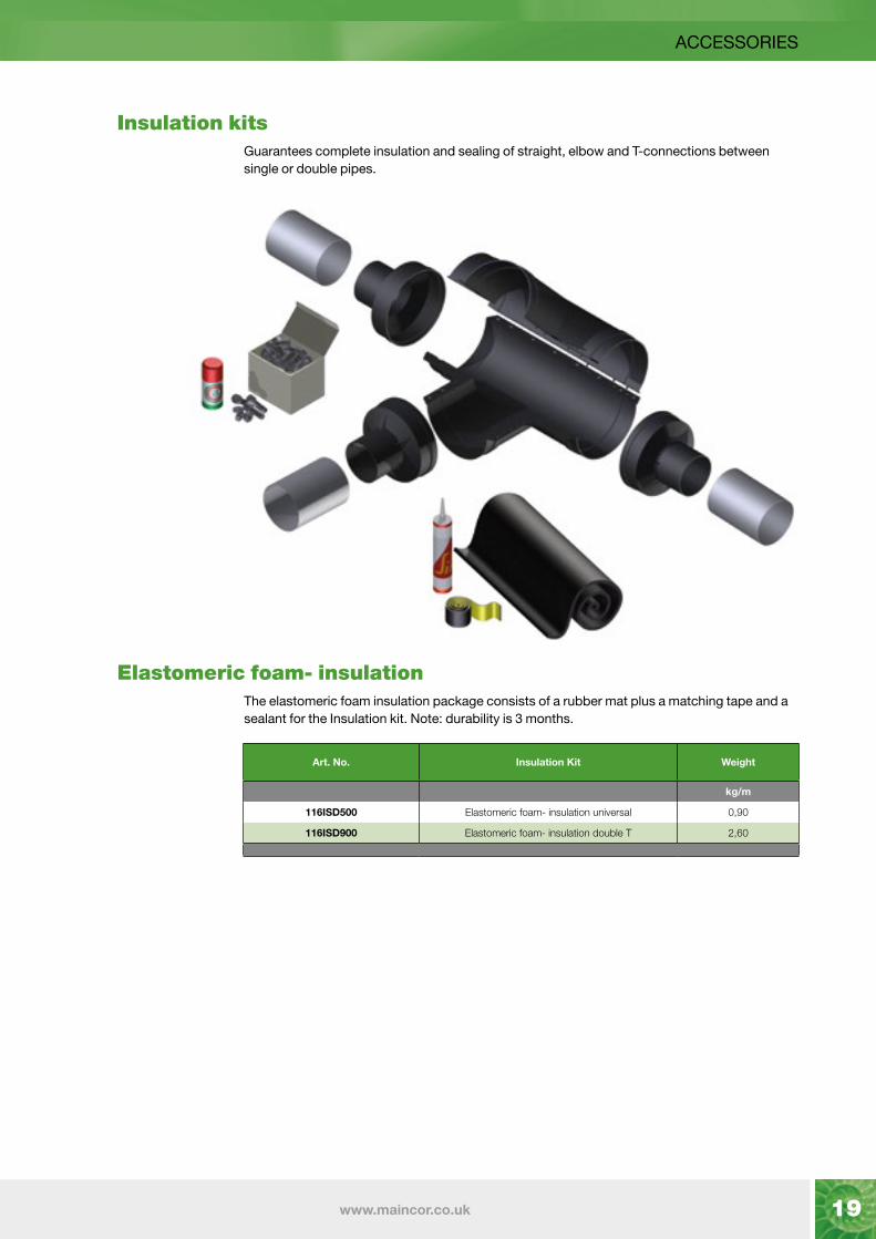
ACCESSORIES
Insulation kits Guarantees complete insulation and sealing of straight, elbow and T-connections between
single or double pipes.
Elastomeric foam- insulation The elastomeric foam insulation package consists of a rubber mat plus a matching tape and a
sealant for the Insulation kit. Note: durability is 3 months.
Art. No. Insulation Kit Weight
kg/m
116ISD500 Elastomeric foam- insulation universal 0,90
116ISD900 Elastomeric foam- insulation double T 2,60

20 MAINCOR
ACCESSORIES
Shroud kits The shroud kits consists of two HDPE- shells, stainless steel bolts, a lubricant against fretting
and installation guidelines. ATTENTION : Don’t forget to order the correctly sized sealing rings and the elastomeric foam insulation.
Insulation Sealing Rings The sealing rings come with shrink tubing to seal the outer casing.
T-Shroud set for tee connections
L-Shroud set for elbow 90° connections
I-Shroud set for straight connections
Art. No. Outer Casing (O.D.) Length Weight
mm mm kg/m
116IRE125090 125 230 0,90
116IRE145150 145 230 0,95
116IRE175150 175 230 1,00
116IRE200200 200 230 1,10
116IRE250200 250 + 240 230 1,25
Art. No. Outer Casing (O.D.) Length Width Height Weight
mm mm mm mm kg/m
116IST005 universal 1070 730 300 5,75
Art. No. Outer Casing (O.D.) Length Width Height Weight
mm mm mm mm kg/m
116ISE003 universal 730 730 300 4,25
Art. No. Outer Casing (O.D.) Length Width Height Weight
mm mm mm mm kg/m
116IST005 universal 1070 160 300 4,75

21www.maincor.co.uk
LONG TIME BEHAVIOUR
Period of time - inner pressure resistance Allowable working pressure according to DIN 16892/93 based on the flow medium water and
are calculated with a safety factor of 1.25 (in accordance with DIN EN ISO 12162). The values are monitored by long-term studies and tested and confirmed by independent test institutes in different countries. The maximum operating temperature is set at 95°C, but a temporary overheating (malfunction temperature) of 110°C is taken into account. The pressure and temperature limits of the pipes depends on the combination of pressure, temperature and time. These technical data are determined in accordance with DIN 16892/93 and can only give a general statement on the long-term rupture strength, because the maximum temperature and pressure in the concrete application can vary widely.
Long-term behaviour in response to temperature and pressure:
average workingtemperature
Working pressure (SDR11)
°C bar years of operation
40 11,9 50
50 10,6 50
60 9,5 50
70 8,5 50
80 7,6 25
90 6,9 15
average workingtemperature
Working pressure (SDR7.4)
°C bar years of operation
40 18,9 50
50 16,8 50
60 15,0 50
70 13,4 50
80 12,1 25
90 11,0 15
6 bar Heating
10 bar Sanitary

22 MAINCOR
Installation time - pipe The installation time is highly dependant on local conditions. Obstacles, use of tools and
weather can have a significant impact on the installation.
Installation time - accessories
Outer Casing (O.D.) Time* Number of workers
mm min/100m Single
125 40 3
145 50 3
175 60 4
200 90 5
240 100 5
250 120 6
mm min/100m Double
125 40 3
145 50 3
175 60 4
200 75 4
240 100 5
* All installation times are approximate and refer to 100 m pipe. Transport and digging not included.
Accessories Time* Number of workers
min
Terminal connections PE-X/PE-X up to O.D. 63 30 1
Terminal connections PE-X/PE-X O.D. 75 to O.D. 110 40 1
Terminal connections PE-X/PE-X O.D. 125 to O.D. 160 50 2
Tees PE-X up to O.D. 63 60 1
Tees PE-X O.D. 75 and O.D. 110 80 1
Tees PE-X O.D. 75 and O.D. 110 120 2
I-Shroud set 125–250 40 1
T-Shroud set 125–250 60 2
Heat shrink caps Ø 125–250 mm 30 1
* All installation times are approximate
INSTALLATION GUIDELINES

23www.maincor.co.uk
INSTALLATION GUIDELINES
Groundwork and laying of the pipe AustroPUR pipes are laid in trenches in the ground.
The following guidelines should be followed during pipe installation:
• Lay the pipes in a bed of sand (min. 10 cm); grain size 0-4mm.
• Avoid damaging the casing, remove sharp objects from the trench.
• Always grasp the transport pipe and not the outer casing.
• Only use pulling and lift assistance which does not harm the outer casing.
• Keep to the stated bending radiuses.
• Lay the line in a serpentine course.
• The code of good craftsmanship for installing underground pipes must be observed. Read our installation instructions.
• Sketch how and where the pipe network runs on a plan (including branches and connections), this plan should be kept in your records.
If possible put the soil on one side of the trench. The following steps can be performed from the other side:
• Position the coil alongside the trench.
• Remove the packaging foil.
• Place the end of the pipe in position.
• Cut the straps layer after layer during the roll-off.
• Roll the pipe alongside or straight into the trench.
• Apply the rubber end caps or shrink caps.
• Connect your pipes with couplings.
• Conduct the pressure test - fill in the report
• Fill the trench with the first sand layer (min 10 cm).
• Apply the warning tape
• Fill in the trench with the soil from the side.
Our pre-insulated pipes as well as our longitudinal, elbow- and T-insulation kits are suitable for the stress caused by heavy goods vehicles SLW 60 under defined installation conditions according to ATV DVWK-A127. The laying of the pipe must be carried out in accordance with the currently applicable guidelines DWA-A127 for underground pipes.
Minimum distance from crossing pipes:
Line Type Minimum distance
1 kV, signal, measuring cables 0,3 m
10-kV- or a 30-kV- cable 0,6 m
Several 30 kV cables or cable >60 kV 1,0 m
Gas and water pipes 0,2 m
Minimum distance from crossing pipes:
Line TypeMinimum distance
for parallel lines
< 5 m > 5 m
1 kV, signal, measuring cables 0,3 m 0,3 m
10-kV- or a 30-kV- cable 0,6 m 0,7 m
Several 30 kV cables or cable >60 kV 1,0 m 1,5 m
Gas and water pipes 0,5 m 0,5 m
Further installation guidelines you will find in our technical manual.

24 MAINCOR
PRESSURE LOSS
5 (K) 7 (K) 10 (K) 15 (K) 20 (K) 25 (K) 30 (K) 40 (K)20 x 1,9
25 x 2,3
32 x 2,9
40 x 3,7
50 x 4,6
63 x 5,8
75 x 6,8
90 x 8,2
kg / h at H2O 70°C
ℓ / sec at H2O 70°C
kW ( at the several Temp. difference in Kelvin z.B.: 20 (K) = 80 / 60°C, TM = 70°C)
1 [ℓ / sec ] x 3,6 = 1 [m³ / h]
Pressure loss
Flow speed. (at H2O 70°C)
O.D. (Outside Diameter PE-Xa carrier pipe times wallthickness SDR11 = 6 bar bei 95°C ) 100.000 Pa = 1 bar
43 0,012 0,25 0,35 0,5 0,75 1 1,25 1,5 2Pa/m m/sec
5 0,06
2 0,04
107 0,031 0,625 0,875 1,25 1,875 2,5 3,125 3,75 5Pa/m m/sec
24 0,15
8 0,09
215 0,061 1,25 1,75 2,5 3,75 5 6,25 7,5 10Pa/m m/sec
80 0,30
27 0,19
8 0,11
430 0,122 2,5 3,5 5 7,5 10 12,5 15 20Pa/m m/sec
273 0,59
90 0,37
27 0,23
10 0,15
644 0,183 3,75 5,25 7,5 11,25 15 18,75 22,5 30Pa/m m/sec
565 0,89
185 0,56
56 0,34
20 0,22
859 0,244 5 7 10 15 20 25 30 40Pa/m m/sec
952 1,18
310 0,75
93 0,45
32 0,29
11 0,19
1.074 0,305 6,25 8,75 12,5 18,75 25 31,25 37,5 50Pa/m m/sec
1432 1,48
465 0,93
138 0,57
48 0,37
16 0,23
1.289 0,366 7,5 10,5 15 22,5 30 37,5 45 60Pa/m m/sec
647 1,12
192 0,68
67 0,44
23 0,28
1.504 0,427 8,75 12,25 17,5 26,25 35 43,75 52,5 70Pa/m m/sec
858 1,31
254 0,79
88 0,51
30 0,33
1.718 0,488 10 14 20 30 40 50 60 80Pa/m m/sec
1096 1,49
323 0,91
112 0,58
38 0,37
13 0,24
1.933 0,549 11,25 15,75 22,5 33,75 45 56,25 67,5 90Pa/m m/sec
400 1,02
139 0,66
47 0,42
15 0,26
2.148 0,610 12,5 17,5 25 37,5 50 62,5 75 100Pa/m m/sec
485 1,13
168 0,73
57 0,47
19 0,29
2.363 0,671 13,75 19,25 27,5 41,25 55 68,75 82,5 110Pa/m m/sec
577 1,24
199 0,80
67 0,51
22 0,32
2.578 0,732 15 21 30 45 60 75 90 120Pa/m m/sec
677 1,36
233 0,88
79 0,56
26 0,35
2.792 0,793 16,25 22,75 32,5 48,75 65 81,25 97,5 130Pa/m m/sec
785 1,47
270 0,95
91 0,61
30 0,38
3.007 0,854 17,5 24,5 35 52,5 70 87,5 105 140Pa/m m/sec
899 1,58
309 1,02
104 0,65
34 0,41
3.222 0,915 18,75 26,25 37,5 56,25 75 93,75 112,5 150Pa/m m/sec
1021 1,70
350 1,10
118 0,70
39 0,44
3.437 0,976 20 28 40 60 80 100 120 160Pa/m m/sec
394 1,17
132 0,75
43 0,47
18 0,33
3.652 1,037 21,25 29,75 42,5 63,75 85 106,25 127,5 170Pa/m m/sec
441 1,24
148 0,79
48 0,50
20 0,35
3.866 1,098 22,5 31,5 45 67,5 90 112,5 135 180Pa/m m/sec
489 1,32
164 0,84
54 0,53
23 0,37
4.296 1,220 25 35 50 75 100 125 150 200Pa/m m/sec
594 1,46
199 0,93
65 0,59
27 0,41
4.726 1,343 27,5 38,5 55 82,5 110 137,5 165 220Pa/m m/sec
709 1,61
237 1,03
77 0,65
33 0,45
5.155 1,465 30 42 60 90 120 150 180 240Pa/m m/sec
833 1,76
277 1,12
90 0,71
38 0,49
5.585 1,587 32,5 45,5 65 97,5 130 162,5 195 260Pa/m m/sec
966 1,90
321 1,21
104 0,76
44 0,54
6.014 1,709 35 49 70 105 140 175 210 280Pa/m m/sec
1108 2,05
368 1,31
119 0,82
50 0,58
6.444 1,831 37,5 52,5 75 112,5 150 187,5 225 300Pa/m m/sec
418 1,40
135 0,88
57 0,62
6.874 1,953 40 56 80 120 160 200 240 320Pa/m m/sec
471 1,49
152 0,94
64 0,66
27 0,46
7.303 2,075 42,5 59,5 85 127,5 170 212,5 255 340Pa/m m/sec
526 1,59
170 1,00
72 0,70
30 0,49
7.733 2,197 45 63 90 135 180 225 270 360Pa/m m/sec
585 1,68
189 1,06
80 0,74
33 0,52
8.592 2,441 50 70 100 150 200 250 300 400Pa/m m/sec
711 1,87
229 1,18
96 0,82
40 0,57
9.666 2,746 56,25 78,75 112,5 168,75 225 281,25 337,5 450Pa/m m/sec
885 2,10
285 1,32
120 0,93
50 0,65
10.740 3,051 62,5 87,5 125 187,5 250 312,5 375 500Pa/m m/sec
1077 2,33
346 1,47
145 1,03
60 0,72
11.814 3,356 68,75 96,25 137,5 206,25 275 343,75 412,5 550Pa/m m/sec
412 1,62
173 1,13
71 0,79
12.888 3,661 75 105 150 225 300 375 450 600Pa/m m/sec
485 1,76
203 1,24
84 0,86
13.962 3,966 81,25 113,75 162,5 243,75 325 406,25 487,5 650Pa/m m/sec
562 1,91
235 1,34
97 0,93

25www.maincor.co.uk
PRESSURE LOSS
5 (K) 7 (K) 10 (K) 15 (K) 20 (K) 25 (K) 30 (K) 40 (K)63 x 5,8
75 x 6,8
90 x 8,2
110 x 10,0
125 x 11,4
160 x 14,6
kg / h at H2O 70°C
ℓ / sec at H2O 70°C
kW ( at the several Temp. difference in Kelvin z.B.: 20 (K) = 80 / 60°C, TM = 70°C)
1 [ℓ / sec ] x 3,6 = 1 [m³ / h]
Pressure loss
Flow speed. (at H2O 70°C)
O.D. (Outside Diameter PE-Xa carrier pipe times wallthickness SDR11 = 6 bar bei 95°C )
100.000 Pa = 1 bar
15.036 4,272 87,5 122,5 175 262,5 350 437,5 525 700Pa/m m/sec
645 2,06
269 1,44
111 1,00
42 0,67
23 0,52
16.110 4,577 93,75 131,25 187,5 281,25 375 468,75 562,5 750Pa/m m/sec
734 2,21
306 1,55
126 1,08
47 0,72
26 0,56
17.184 4,882 100 140 200 300 400 500 600 800Pa/m m/sec
828 2,35
345 1,65
142 1,15
53 0,77
29 0,60
18.258 5,187 106,25 148,75 212,5 318,75 425 531,25 637,5 850Pa/m m/sec
927 2,50
386 1,75
159 1,22
60 0,82
32 0,63
19.332 5,492 112,5 157,5 225 337,5 450 562,5 675 900Pa/m m/sec
1032 2,65
429 1,85
176 1,29
66 0,86
36 0,67
20.406 5,797 118,75 166,25 237,5 356,25 475 593,75 712,5 950Pa/m m/sec
475 1,96
195 1,36
73 0,91
39 0,71
21.480 6,102 125 175 250 375 500 625 750 1000Pa/m m/sec
522 2,06
214 1,43
80 0,96
43 0,74
22.554 6,407 131,25 183,75 262,5 393,75 525 656,25 787,5 1050Pa/m m/sec
572 2,16
234 1,51
88 1,01
47 0,78
23.628 6,713 137,5 192,5 275 412,5 550 687,5 825 1100Pa/m m/sec
624 2,27
256 1,58
96 1,06
51 0,82
16 0,50
24.702 7,018 143,75 201,25 287,5 431,25 575 718,75 862,5 1150Pa/m m/sec
678 2,37
278 1,65
104 1,10
56 0,86
17 0,52
25.776 7,323 150 210 300 450 600 750 900 1200Pa/m m/sec
734 2,47
300 1,72
112 1,15
60 0,89
18 0,54
26.850 7,628 156,25 218,75 312,5 468,75 625 781,25 937,5 1250Pa/m m/sec
792 2,58
324 1,79
121 1,20
65 0,93
20 0,57
27.924 7,933 162,5 227,5 325 487,5 650 812,5 975 1300Pa/m m/sec
853 2,68
349 1,86
130 1,25
70 0,97
21 0,59
28.998 8,238 168,75 236,25 337,5 506,25 675 843,75 1012,5 1350Pa/m m/sec
916 2,78
374 1,94
139 1,29
75 1,00
23 0,61
30.072 8,543 175 245 350 525 700 875 1050 1400Pa/m m/sec
980 2,89
400 2,01
149 1,34
80 1,04
24 0,64
31.146 8,848 181,25 253,75 362,5 543,75 725 906,25 1087,5 1450Pa/m m/sec
427 2,08
159 1,39
85 1,08
26 0,66
32.217 9,153 187,5 262,5 375 562,5 750 937,5 1125 1500Pa/m m/sec
455 2,15
169 1,44
91 1,12
27 0,68
33.294 9,459 193,75 271,25 387,5 581,25 775 968,75 1162,5 1550Pa/m m/sec
484 2,22
180 1,49
97 1,15
29 0,70
34.368 9,764 200 280 400 600 800 1000 1200 1600Pa/m m/sec
514 2,29
191 1,53
102 1,19
31 0,73
36.516 10,374 212,5 297,5 425 637,5 850 1062,5 1275 1700Pa/m m/sec
575 2,44
214 1,63
115 1,26
34 0,77
38.664 10,984 225 315 450 675 900 1125 1350 1800Pa/m m/sec
640 2,58
237 1,73
127 1,34
38 0,82
40.812 11,594 237,5 332,5 475 712,5 950 1187,5 1425 1900Pa/m m/sec
709 2,73
263 1,82
141 1,41
42 0,86
42.959 12,205 250 350 500 750 1000 1250 1500 2000Pa/m m/sec
781 2,87
289 1,92
155 1,49
46 0,91
45.107 12,815 262,5 367,5 525 787,5 1050 1312,5 1575 2100Pa/m m/sec
317 2,01
169 1,56
51 0,95
47.255 13,425 275 385 550 825 1100 1375 1650 2200Pa/m m/sec
345 2,11
185 1,64
55 1,00
49.403 14,035 287,5 402,5 575 862,5 1150 1437,5 1725 2300Pa/m m/sec
375 2,21
201 1,71
60 1,04
51.551 14,646 300 420 600 900 1200 1500 1800 2400Pa/m m/sec
406 2,30
217 1,79
65 1,09
53.699 15,256 312,5 437,5 625 937,5 1250 1562,5 1875 2500Pa/m m/sec
439 2,40
234 1,86
70 1,14
55.848 15,866 325 455 650 975 1300 1625 1950 2600Pa/m m/sec
472 2,49
252 1,93
75 1,18
57.995 16,476 337,5 472,5 675 1012,5 1350 1687,5 2025 2700Pa/m m/sec
507 2,59
270 2,01
81 1,23
60.143 17,086 350 490 700 1050 1400 1750 2100 2800Pa/m m/sec
290 2,08
86 1,27
62.291 17,697 362,5 507,5 725 1087,5 1450 1812,5 2175 2900Pa/m m/sec
309 2,16
92 1,32
64.439 18,307 375 525 750 1125 1500 1875 2250 3000Pa/m m/sec
329 2,23
98 1,36
66.587 18,917 387,5 542,5 775 1162,5 1550 1937,5 2325 3100Pa/m m/sec
350 2,31
104 1,41
68.735 19,527 400 560 800 1200 1600 2000 2400 3200Pa/m m/sec
372 2,38
110 1,45
Max transmissable power
3200 [kW]
at 20[K] Temp. difference.
For further information
pleas contact us.
26 MAINCOR
PRESSURE TEST
Pressure TestThe pressure test procedure is obligatory before closing the trench!Leak-tightness testing with water:1. Pipes must be accessible and must not be covered.
2. Dismantle safety and counting devices where required and replace with pipe pieces or pipe end stops.
3. Fill pipes from the deepest point of the system, excluding any air, with filtered drinking water. Here the water temperature must match the ambient temperature (Δ ϑ ≤ 10 K ambient temperature to water temperature)
4. Bleed the draw-off points until no air can be determined in the expelled water.
5. Use a pressure testing device with an accuracy of 100 hPa (0.1 bar) for the pressure test.
6. Connect the pressure testing device at the deepest point of the heating network system.
7. Carefully close all draw-off points.
8. Make sure that the temperature remains as constant as possible during the pressure test.
9. Prepare the pressure test record sheet and note the system data.
The filling water is filtered and the pipesystem is without any air. The allowable working pressure is:_______ bar
Water temperature ϑW =_______ °C Ambient temperature ϑA=_______ °C Δϑ = ϑA –ϑW = _______K
2. Pressure test
Step 1:
Δϑ ≤ 10 K between ambient temperature and water temperature
Test pressure: _______ bar (1,1 x max. working pressure) Waiting time: _______ min. (minimum 30 minutes); hold test pressure, repressurise when necessary.
Pressure after 30 min.: _______ bar
The whole installation, especially the connections, are checked and no leaks are detected.
Step 2: Test pressure: _______ bar (0,5 x max. test pressure) Test time: _______ min. (120 min.) Pressure after 120 min.:_______ bar
The whole installation, especially the connections, are checked and no leaks are detected.
3. Check notes At step 2 of the pressure test no pressure loss at the
manometer was detected.
The whole installation is sealed.
4. Confirmation For the client:
For the Contractor:
Place:
Date:
Attachment:
Pressure test for system with PE-Xa-pipes:1. Build up the test pressure (= 1.1 x max. operating pressure)
slowly in the installation.
2. Maintain the test pressure for 30 minutes. Build up the test pressure again where necessary.
3. Note down the test pressure in the pressure test record after 30 minutes.
4. Verify the leaktightness of the entire installation, particularly the connecting points, by means of a visual inspection.
5. Slowly reduce the test pressure to 0.5 x maximum test pressure and note down the test pressure in the pressure test report.
6. Read the test pressure after 2 hours and note it down in the pressure test record.
7. Verify the leaktightness of the entire installation, particularly the connecting points, by means of a visual inspection.
8. If the test pressure drops away: -Carry out another precise visual inspection of the pipes, draw-off points and connecting points. -After rectifying the cause of the drop in pressure repeat the pressure test on the system (steps 1-7).
9. If no leaks have been found during the visual inspection the leaktightness test can be concluded.
Concluding the pressure test with water Following conclusion of the pressure test:1. The company that performed the test and the client must
confirm the pressure test in the pressure test record.
2. Remove the pressure test device.
3. Re-attach the removed safety and metering equipment.
Pressure test record 1. Project data:
Object: Builder:
Street/No.: ZIP/Place:
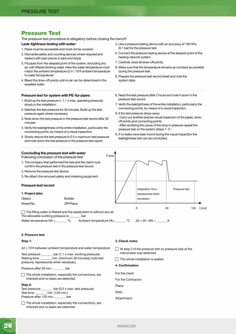
Adaptation time -
repressurise when
necessary
Pressure test
300 150
P [bar]
t [min]

27www.maincor.co.uk
HEAT LOSS
Heat loss AustroPUR single (heating 6 bar) Overburden: 800 mm λGround: 1,0 [W/m . K] Tf = Temperature flow Tg = Temperature ground
Heat loss in W/m at ΔT = Tf-Tg
Δ T [K]
Dimension10 20 30 40 50 60 70 80 90 100
U-value [W/m-K]
A125 1x25 0.9 1.8 2.7 3.6 4.5 5.39 6.29 7.19 8.09 8.99 0.0899
A125 1x32 1.07 2.14 3.22 4.29 5.36 6.43 7.5 8.58 9.65 10.72 0.1072
A125 1x40 1.3 2.59 3.89 5.19 6.49 7.78 9.08 10.38 11.67 12.97 0.1297
A125 1x50 1.64 3.29 4.93 6.57 8.22 9.86 11.5 13.14 14.79 16.43 0.1643
A145 1x63 1.78 3.55 5.33 7.1 8.88 10.66 12.43 14.21 15.98 17.76 0.1776
A175 1x75 1.76 3.51 5.27 7.02 8.78 10.54 12.29 14.05 15.8 17.56 0.1756
A200 1x110 2.48 4.95 7.43 9.91 12.39 14.86 17.34 19.82 22.29 24.77 0.2477
A240 1x125 2.24 4.47 6.71 8.95 11.19 13.42 15.66 17.9 20.13 22.37 0.2237
A250 1x160 2.82 5.63 8.45 11.26 14.08 16.89 19.71 22.52 25.34 28.15 0.2815
Heat loss AustroPUR twin (heating 6 bar)
Overburden: 800 mm λGround: 1,0 [W/m . K] Tf = Temperature flow Tg = Temperature ground
Heat loss in W/m at ΔT = Tf-Tg
Δ T [K]
Dimension10 20 30 40 50 60 70 80 90 100
U-value [W/m-K]
A125 2x25 1.58 3.15 4.73 6.31 7.89 9.46 11.04 12.62 14.19 15.77 0.1577
A125 2x32 2.12 4.24 6.36 8.48 10.6 12.71 14.83 16.95 19.07 21.19 0.2119
A145 2x40 2.25 4.49 6.74 8.98 11.23 13.47 15.72 17.96 20.21 22.45 0.2245
A175 2x50 2.34 4.68 7.02 9.36 11.71 14.05 16.39 18.73 21.07 23.41 0.2341
A200 2x63 2.52 5.03 7.55 10.07 12.59 15.1 17.62 20.14 22.65 25.17 0.2517
A240 2x75 2.53 5.05 7.58 10.11 12.64 15.16 17.69 20.22 22.74 25.27 0.2527

Underfloor Heating Radiator Heating Plumbing Pre-Insulated Pipe
Follow us on
Maincor supports and/or is a member of:
January 2020
Maincor Limited Elizabethan Way, Lutterworth, Leicestershire, LE17 4NJ
T 01455 555 930 E [email protected] W www.maincor.co.uk


