Any reproduction of this document must be done in full. No single part of this document may be reproduced without permission from STS, All Test Data Presented in this report is only applicable to presented Test sample. Shenzhen STS Test Services Co., Ltd. 1/F., Building B, Zhuoke Science Park, No.190, Chongqing Road, Fuyong Street, Bao’an District, Shenzhen, Guangdong, China TEL: +86-755 3688 6288 FAX: +86-755 3688 6277 E-mail:[email protected]JAPAN TEST REPORT Report No:STS1902020W01 Issued for MARUBENI INFORMATION SYSTEMS CO., LTD Shinjuku Garden Tower 3-8-2, Okubo, Shinjuku-ku, Tokyo Japan Product Name: MBTWatch Brand Name: MBTLink Test Model Name: MBT-01 Series Model: N/A Test Standard: Article 2 Paragraph 1 of Item 19, annex 43 and annex 1 S T L A B S
Transcript
Any reproduction of this document must be done in full. No single part of this document may be reproduced without permission from STS, All Test Data Presented in this report is only applicable to presented Test sample. Shenzhen STS Test Services Co., Ltd. 1/F., Building B, Zhuoke Science Park, No.190, Chongqing Road, Fuyong Street, Bao’an District, Shenzhen, Guangdong, China TEL: +86-755 3688 6288 FAX: +86-755 3688 6277 E-mail:[email protected]
JAPAN TEST REPORT
Report No:STS1902020W01
Issued for
MARUBENI INFORMATION SYSTEMS CO., LTD
Shinjuku Garden Tower 3-8-2, Okubo, Shinjuku-ku, Tokyo Japan
Product Name: MBTWatch
Brand Name: MBTLink
Test Model Name: MBT-01
Series Model: N/A
Test Standard: Article 2 Paragraph 1 of Item 19, annex 43 and annex 1
S
T
L
A
B
S
Page 2 of 40 Report No.: STS1902020W01
TEST RESULT CERTIFICATION
Applicant’s name ........................... : MARUBENI INFORMATION SYSTEMS CO., LTD
Address ...................................... : Shinjuku Garden Tower 3-8-2, Okubo, Shinjuku-ku, Tokyo Japan
Manufacture's Name ...................... : Shenzhen Qianhaiyifan Technology Co.,Ltd
Address ...................................... : Six Floor Xingguangbao Industrial park Huaning Road Dalang Longhua Shenzhen China
Test specification:
Standard .................................... : Article 2 Paragraph 1 of Item 19, annex 43 and annex 1
Product description
Product name……………………: MBTWatch
Trade mark………………...….….: MBTLink
Test model name……….…….…: MBT-01
Series model…………….……….: N/A
This device described above has been tested by STS, the test results show that the equipment under test (EUT) is in compliance with Article 2 Paragraph 1 of Item 19, annex 43 and annex 1 requirements. And it is applicable only to the tested sample identified in the report.
This report shall not be reproduced except in full, without the written approval of STS, this document may be altered or revised by STS, personal only, and shall be noted in the revision of the document
4.11 3.7 Construction Protection Confirmation -- PASS
NOTE:
(1)” N/A” denotes test is not applicable in this Test Report
(2) Article 2 Paragraph 1 of Item 19, annex 43 and annex 1
(3) Section 4.17 Radio Equipment of Radio Stations of a Low-Power Data Communication
System (Article 49.20)
Page 7 of 40 Report No.: STS1902020W01
1.1 TEST FACTORY
Shenzhen STS Test Services Co., Ltd. Add. : 1/F., Building B, Zhuoke Science Park, No.190, Chongqing Road, Fuyong Street, Bao’an District, Shenzhen, Guangdong, China
FCC Registration No.: 625569
IC Registration No.: 12108A; A2LA Certificate No.: 4338.01;
1.2 MEASUREMENT UNCERTAINTY
The reported uncertainty of measurement y ± U,where expended uncertainty U is based on a
standard uncertainty multiplied by a coverage factor of k=2,providing a level of confidence of
approximately 95 %。
No. Item Uncertainty
1 RF output power,conducted ±0.71dB
2 Unwanted Emissions,conducted ±0.63dB
Page 8 of 40 Report No.: STS1902020W01
2. GENERAL INFORMATION
2.1 GENERAL DESCRIPTION OF THE EUT
Equipment MBTWatch
Brand Name MBTLink
Model Name MBT-01
Series Model N/A
Model
Difference N/A
Product
Description
The EUT is MBTWatch
Operation Frequency: 2402~2480 MHz
Modulation Type: GFSK
Number Of Channel: 40CH
Antenna Designation: PCB Antenna
Antenna Gain(Peak): 0 dBi
Based on the application, features, or specification exhibited in User's Manual, the EUT is considered as an ITE/Computing Device. More details of EUT technical specification, please refer to the User's Manual.
Channel List Please refer to the Note 2.
Battery
Battery(rating):
Rated Voltage: 3.7V
Charge Limit: 4.2V
Capacity: 100 mAh
Hardware
version MRD-HB030-.2_V2.3
Software
version V 224
Note:
1. For a more detailed features description, please refer to the manufacturer’s specifications or the User's Manual.
Page 9 of 40 Report No.: STS1902020W01
2 Channel List for BLE
Channel Frequency
(MHz) Channel
Frequency
(MHz) Channel
Frequency
(MHz) Channel
Frequency
(MHz)
37 2402 09 2422 18 2442 28 2462
00 2404 10 2424 19 2444 29 2464
01 2406 38 2426 20 2446 30 2466
02 2408 11 2428 21 2448 31 2468
03 2410 12 2430 22 2450 32 2470
04 2412 13 2432 23 2452 33 2472
05 2414 14 2434 24 2454 34 2474
06 2416 15 2436 25 2456 35 2476
07 2418 16 2438 26 2458 36 2478
08 2420 17 2440 27 2460 39 2480
3. Table for Filed Antenna
Ant. Brand Model Name Antenna Type Connector Gain (dBi)
NOTE
1 MBTLink MBT-01 PCB Antenna N/A 0 BLE ANT.
Page 10 of 40 Report No.: STS1902020W01
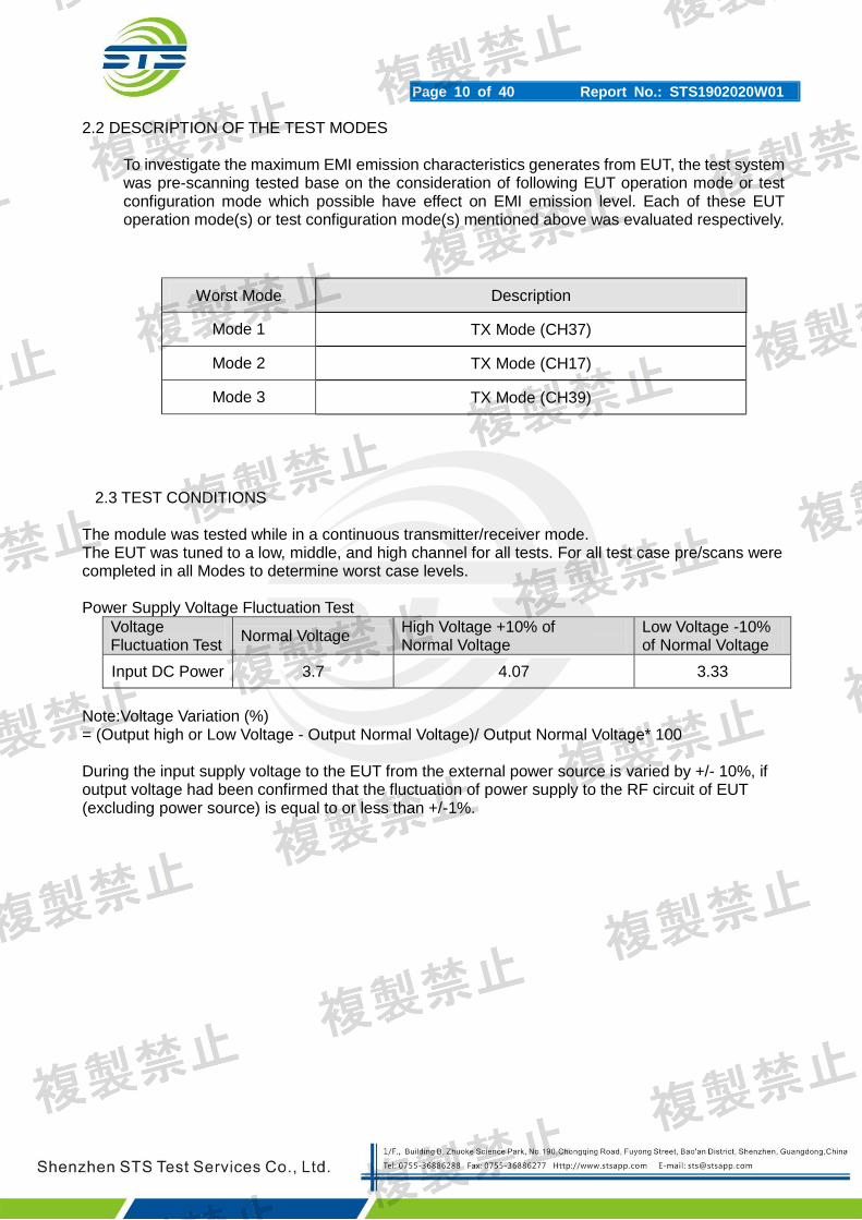
2.2 DESCRIPTION OF THE TEST MODES
To investigate the maximum EMI emission characteristics generates from EUT, the test system was pre-scanning tested base on the consideration of following EUT operation mode or test configuration mode which possible have effect on EMI emission level. Each of these EUT operation mode(s) or test configuration mode(s) mentioned above was evaluated respectively.
Worst Mode Description
Mode 1 TX Mode (CH37)
Mode 2 TX Mode (CH17)
Mode 3 TX Mode (CH39)
2.3 TEST CONDITIONS
The module was tested while in a continuous transmitter/receiver mode. The EUT was tuned to a low, middle, and high channel for all tests. For all test case pre/scans were completed in all Modes to determine worst case levels. Power Supply Voltage Fluctuation Test
Voltage Fluctuation Test
Normal Voltage High Voltage +10% of Normal Voltage
Low Voltage -10% of Normal Voltage
Input DC Power 3.7 4.07 3.33
Note:Voltage Variation (%) = (Output high or Low Voltage - Output Normal Voltage)/ Output Normal Voltage* 100 During the input supply voltage to the EUT from the external power source is varied by +/- 10%, if output voltage had been confirmed that the fluctuation of power supply to the RF circuit of EUT (excluding power source) is equal to or less than +/-1%.
Page 11 of 40 Report No.: STS1902020W01
2.4 BLOCK DIGRAM SHOWING THE CONFIGURATION OF SYSTEM TESTED
Mode 1:
2.5 DESCRIPTION OF NECESSARY ACCESSORIES AND SUPPORT UNITS
The EUT has been tested as an independent unit together with other necessary accessories or support units. The following support units or accessories were used to form a representative test configuration during the tests.
Necessary accessories
Item Equipment Mfr/Brand Model/Type No. Serial No. Note
N/A N/A N/A N/A N/A N/A
Support units
Item Equipment Mfr/Brand Model/Type No. Serial No. Note
E-2 Notebook HP 500-320cx N/A N/A
C-1 USB Cable N/A 100cm N/A N/A
Note:
(1) The support equipment was authorized by Declaration of Confirmation. (2) For detachable type I/O cable should be specified the length in cm in『Length』column.
(3) “YES” is means “shielded” “with core”; “NO” is means “unshielded” “without core”.
E-1 EUT
E-2 Notebook
C-1
Page 12 of 40 Report No.: STS1902020W01
2.6 EQUIPMENTS LIST FOR ALL TEST ITEMS
Test equipment
Kind of Equipment Manufacturer Type No. Serial No. Last calibration Calibrated until
USB RF power sensor DARE RPR3006W 15I00041SNO03 2018.10.13 2019.10.12
Temperature& Humidity test chamber
Safety test AG80L 171200018 2018.03.09 2019.03.08
Signal Analyzer Agilent N9020A MY49100060 2018.10.13 2019.10.12
Signal Generator Agilent N5182A MY46240556 2018.10.16 2019.10.15
All of the test equipment is effective use and calibration certification institution, GRGT, the address is 163 tianhe district in huangpu road xiping cloud road .Guangzhou, China
Page 13 of 40 Report No.: STS1902020W01
3. CONSTRUCTION PROTECTION CONFIRMATION
Our products apply for Japanese radio frequency (rf) certification. The high-frequency section and modulation section use SMT technology, not easy to change.( The chip have more than 10 chip pins, less than 1.5mm pin dastance.)
Page 14 of 40 Report No.: STS1902020W01
4. FREQUENCY ERROR 4.1 LIMIT
Item Limits
Frequency Error ±50ppm
4. 2 TEST PROCEDURES The following table is the setting of Spectrum Analyzer.
Spectrum Parameter Setting
Attenuation Auto
RB / VB 10KHz
Detector Peak
Trace Max Hold
Sweep Time Auto
(1)In the case of unmodulated signal (continuous or continuous burst), measure the frequency directly by a frequency meter.
(2)In the case of burst waves, the measurement shall be done for enough time in order to obtain the enough measuring accuracy, and the average of the measured values becomes the final value.
(3)In the case of a test mode with a specific frequency spectrum, measure the frequency of the specific spectrum by a spectrum analyzer.
(4)In the cases above, if the frequency equivalent to the test frequency is not directly measured in principle, it shall be obtained by necessary calculation.
In the case of modulated signal, if there is no specific spectrum measurable by a spectrum analyzer but a specific dip is observed, it is allowed to measure the frequency with the signal generator (synthesized). That is, observe a signal of the signal generator concurrently (or alternately) with the tested signal using the spectrum analyzer while setting the frequency of the signal generator to the position of the dip on the screen of the spectrum analyzer, and determine the frequency of the signal generator at the time as a measured value.
4.3 TEST SETUP
4.4 EUT OPERATION DURING TEST The EUT was placed on the test table and programmed in un-modulation function. .
Power Error +20%, -80% (Base on manufacturer declare power)
5.2 TEST PROCEDURE 1. EUT turn to test frequency channel and keep continuous transmiting 2. Reading the output power from the Power meter as PEUT 3. Turn the Signal generator to frequency channel the same as the EUT 4. Turn the level of Signal generator, scan with the power meter until the power equal to PEUT, the level of Signal generator recorded as “P” 5. The antenna power of EUT is “P”. 6. EIRP power=“P”+antenna gain
5.3 TEST SETUP
5.4 TEST DEVIATION
There is no deviation with the original standard.
Page 19 of 40 Report No.: STS1902020W01
5.5 TEST RESULT
Temperature: 250C Humidity: 55 % RH
Operation Mode: (Nor/Max/Min)Voltage TX mode
Antenna Power Density
TEST CONDITIONS Channel
(MHz) Ant output
POWER (dBm) Ant output
(mW)
Declared Power (mW)
Tolerance
%
Vnom(V) 3.7 2402 0.0220 1.005 1.5000 -32.99
2440 -0.1440 0.967 1.5000 -35.51
2480 0.5620 1.138 1.5000 -24.12
Vmax(V) 4.07 2402 0.0148 1.003 1.5000 -33.11
2440 -0.1526 0.965 1.5000 -35.64
2480 0.5592 1.137 1.5000 -24.17
Vmin(V) 3.33 2402 0.0183 1.004 1.5000 -33.05
2440 -0.1473 0.967 1.5000 -35.56
2480 0.5553 1.136 1.5000 -24.24
Limit : (1) Antenna Power Density Limit (10mW) (2) Tolerance +20%, -80% (Base on manufacturer declare Antenna Power Density)
Page 20 of 40 Report No.: STS1902020W01
6. RADIATION POWER
6.1 LIMIT
Item Limits
Radiation power EIRP
FH form 2400 – 2483.5 MHz ,EIRP≦6.91dBm/MHz
CCK/OFDM/DBPSK (2400~2483.5MHz)
OFDM or DS other than (802.11b/g/n HT20) EIRP≦12.14 dBm/MHz
OFDM or DS other than (802.11n HT40) EIRP≦9.13dBm/MHz
Other from 2400~2483.5MHz: 12.14 dBm or less
Power Error +20%, -80% (Base on manufacturer declare power)
. 6.2 TEST RESULT Note: The antenna gain is less than 2.14dBi, no requirement.
Page 21 of 40 Report No.: STS1902020W01
7. OCCUPIED BANDWITH AND SPREAD BANDWIDTH
7.1 LIMIT
Item Limits
Occupied Band Width: ≤83.5MHz(FH;FH+DS;FH+OFDM)
≤26MHz(Others)
Spreading Bandwidth: ≧500 kHz
7.2 TEST PROCEDURES
1. Setting of SA is following as: RB: 100KHz / VB:100KHz / SPAN: 2MHz / AT: 20dB Ref:10dBm / Sweep time: Auto / Sweep Mode: Continuous sweep / Detect mode: Positive peak / Trace mode: Max hold
2 . EUT have transmitted the maximum modulation signal and fixed channelize ( For DSSS or OFDM Device) or continuous maximum power of hopping mode(For FHSS Device). SA set to 99% of occupied bandwidth to measure occupied bandwidth. The limit is less than 26MHz(For DSSS or OFDM Device) or 83.5MHz(For FHSS Device).
3. SA set to 90% of occupied bandwidth to measure Spread Spectrum Bandwidth and must greater than 500kHz.
7.3 TEST SETUP
7.4 TEST DEVIATION
There is no deviation with the original standard. 7.5 EUT OPERATION DURING TEST
The EUT was programmed to be in continuously transmitting mode.
Page 22 of 40 Report No.: STS1902020W01
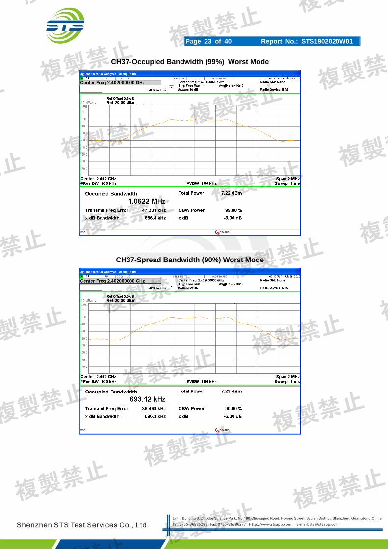
7.6 TEST RESULT
Temperature: 250C Humidity: 55 % RH
Operation Mode: (Nor/Max/Min)Voltage TX mode
DC Voltage channel (MHz)
Occupied Bandwidth
(MHz)
Spread Bandwidth
(MHz)
Nor Voltage(V) 3.7
2402 1.062 0.693
2440 1.065 0.695
2480 1.066 0.697
Max Voltage(V) 4.07
2402 1.060 0.691
2440 1.062 0.692
2480 1.063 0.695
Min Voltage(V) 3.33
2402 1.058 0.690
2440 1.061 0.691
2480 1.062 0.693
Page 23 of 40 Report No.: STS1902020W01
CH37-Occupied Bandwidth (99%) Worst Mode
CH37-Spread Bandwidth (90%) Worst Mode
Page 24 of 40 Report No.: STS1902020W01
CH17-Occupied Bandwidth (99%) Mode Worst Mode
CH17-Spread Bandwidth (90%) Mode Worst Mode
Page 25 of 40 Report No.: STS1902020W01
CH39-Occupied Bandwidth (99%) Worst Mode
CH39-Spread Bandwidth (90%) Worst Mode
Page 26 of 40 Report No.: STS1902020W01
8. UNWANTED EMISSION INTENSITY MEASUREMENT
8.1 LIMIT
Item Limits
TX Spurious Emission
≦2.5 μW (30MHz≦f≦1000MHz)
≦2.5 μW (1000MHz<f≦2387MHz)
≦25 μW (2387MHz<f≦2400MHz)
≦25 μW (2483.5MHz≦f<2496.5MHz)
≦2.5 μW (2496.5MHz≦f<12500MHz)
8.2 TEST PROCEDURES
Spectrum Parameter Setting
Attenuation Auto
RB / VB 100KHz /100KHz(Below 1GHz)
RB / VB 1MHz /1MHz (Above 1GHz)
Detector Peak
Trace Max Hold
Sweep Time Auto
1. EUT have transmitted the maximum modulation signal and fixed channelize. 2. Setting of SA is following as: Below 1GHz RB:100KHz / VB:100KHz
Above 1GHz RB:1MHz / VB:1MHz / AT: 10dB Ref: 0dBm / Sweep time: Auto Sweep Mode: Continuous sweep / Detect mode: Positive peak Trace mode: Max hold
3. Setting of SA is following as 30MHz and stop frequency 1000MHz Then to mark peak reading value + cable loss shall be less than 0.25μW.
4. Setting of SA is following as 1000MHz and stop frequency 2387MHz Then to mark peak reading value + cable loss shall be less than 2.5μW.
5. SA adjusted to start frequency 2387MHz and stop frequency 2400MHz. Then to mark peak reading value + cable loss shall be less than 25μW.
6. SA adjusted to start frequency 2483.5MHz and stop frequency 2496.5MHz Then to mark peak reading value + cable loss shall be less than 25μW
7. SA adjusted to start frequency 2496.5MHz and stop frequency 12750MHz Then to mark peak reading value + cable loss shall be less than 2.5μW
8. Measure side band spurious as follows: For 2.4GHz band: 2374MHz~2400MHz and 2483.5MHz~2509.5MHz RBW = VBW = 30kHz, Result_Value = Meaured_ Value + 15.2 [dBm]
9. If the Result_Value is over the requirement, take total sum of 1MHz band centered at the spur frequency like ACLP measurement as Result_Value.
Page 27 of 40 Report No.: STS1902020W01
8.3 TEST SETUP
8.4 TEST DEVIATION There is no deviation with the original standard.
Page 28 of 40 Report No.: STS1902020W01
8.5 TEST RESULT
Temperature: 250C Humidity: 55 % RH
Test Voltage (Nor/Max/Min)Voltage Operation Mode: TX mode
CH 37 (TX mode) - Frequency Band 1 (30 MHz ≦ f ≦ 1000 MHz)
Worst Mode
Page 29 of 40 Report No.: STS1902020W01
CH 37 TX mode - Frequency Band 2 (1000 MHz < f ≦ 2520 MHz)
Worst Mode
CH 37 TX mode - Frequency Band 3 (2520 MHz ≦ f < 12.75 GHz)
Worst Mode
Page 30 of 40 Report No.: STS1902020W01
CH 17 TX mode - Frequency Band 1 (30 MHz ≦ f ≦ 1000 MHz)
Worst Mode
CH 17 TX mode - Frequency Band 2 (1000 MHz < f ≦ 2520 MHz)
Worst Mode
Page 31 of 40 Report No.: STS1902020W01
CH 17 TX mode - Frequency Band 3 (2520 MHz ≦ f < 12.75 GHz)
Worst Mode
CH 39 TX mode - Frequency Band 1 (30 MHz ≦ f ≦ 1000 MHz)
Worst Mode
Page 32 of 40 Report No.: STS1902020W01
CH 39 TX mode - Frequency Band 2 (1000 MHz < f ≦ 2520 MHz)
Worst Mode
CH 39 TX mode - Frequency Band 3 (2520 MHz ≦ f < 12.75 GHz)
Worst Mode
Page 33 of 40 Report No.: STS1902020W01
9. IMITATION OF COLLATERAL EMISSION OF RECEIVER MEASUREMENT
9.1 LIMIT
Item Limits
RX Spurious Emission:
≦4nW (f<1GHz)
≦20nW (1GHz≦f)
9.2 TEST PROCEDURES
The following table is the setting of Spectrum Analyzer.
1. EUT have the continuous reception mode and fixed only one channelize. 2. Setting of SA is following as RB / VB: 100 kHz (below 1GHz emissions) / 1 MHz
mode: Positive peak / Trace mode: Max hold 3. SA set RB: 100kHz and VB: 100kHz. Then adjust to start frequency 30MHz and
stop frequency 1000MHz. Search to mark peak reading value + cable loss shall be less than 4nW
4. SA set RB: 1MHz and VB: 1MHz. Then adjust to start frequency 1000MHz and stop frequency 12750MHz. Search to mark peak reading value + cable loss shall be less than 20nW
5. If power level of lower emissions are more than 1/10 of limit (.0.4nW for f < 1GHz, 2nW for f >= 1GHz), all those are to be indicated in the 2nd and 3rd lines. If others are 1/10 or less more of the limit, no necessary to be indicated.
Page 34 of 40 Report No.: STS1902020W01
9.3 TEST RESULT
Temperature: 250C Humidity: 55 % RH
Operation Mode: (Nor/Max/Min)Voltage RX mode
The worst test channel of all channels was showed as the follow:
RX-Frequency Band 1 (30 MHz ≦ f < 1000 MHz) Worst Mode
RX-Frequency Band 2 (1000 MHz ≦ f < 12750 MHz) Worst Mode
A = {EIRP Power [mW/MHz] /{2.14dBi+output power(10mW /MHz, 3mW/MHz)} Shall be 1 when A is lower than 1
Note: This test item is not applied for radio equipment with equivalent isotropic radiation power lower than 12.14dBm/MHz, but Antenna Power(Conducted) limit is 10 mW/MHz (10 dBm/MHz), So the test item will not be applied to the transmission antenna which has a gain of 2.14dBi or less
10.2 TEST PROCEDURES
Spectrum Parameter Setting
Attenuation Auto
Span Frequency 0 MHz
RB 1 MHz
VB 1 kHz
Detector Peak
Trace Max Hold
Sweep Time Auto
1. Set EUT and measuring antenna at the same height and roughly facing each other. 2. Set spectrum analyzer with condition in section 4.7.2 and tune reference level to
observe receving signal position. 3. Rotate directions of the EUT horizontally and ertically to find the maximum
receiving power. 4. Move the measuring antenna height up and down within ± 50cm of EUT height and
swing it to find the maximum output of measuing antenna. “E” is the half-power beam width (angle between two points at which radiated power becomes 1/2)
5. Caluate permitted radiation angle in horizontal and vertical using EIRP measured in another test method.
6. Calculate 3dB antenna beam width by the formula below 360/A (If A<1; then A=1). A = {EIRP Power [mW/MHz] /{2.14dBi+output power(10mW /MHz, 3mW/MHz)} Shall be 1 when A is lower than 1
Page 36 of 40 Report No.: STS1902020W01
10.3 TEST SETUP
10.4 TEST DEVIATION There is no deviation with the original standard.
10.5 EUT OPERATION DURING TEST The EUT was programmed to be in continuously transmitting mode.
10.6 TEST RESULT Note: The antenna gain is less than 2.14dBi, no requirement.
Page 37 of 40 Report No.: STS1902020W01
11. RADIO INTERFERENCE PREVENTION CAPABILITY MEASUREMENT
11.1 LIMIT
Item Limits
Identification code ≧48 bits
11.2 MEASURING ID CODE SOFTWARE
Item Limits
MAC IP List MAC Scan
11.3 TEST PROCEDURES
1. In the case that the EUT has the function of automatically transmitting the identification code: a. Transmit the predetermined identification codes form EUT. b. Check the transmitted identification codes with the demodulator.
2. In the case of receiving the identification ocde: a. Transmit the predetermined identification codes form the counterpart. b . Check if communication is normal. c. Transmit the signals other than predetermined ID codes form the counterpart. d. check if the EUT stops the transmission, or if it displays that idnetification codes are different from the predetermined ones.
11.4 TEST SETUP
11.5 TEST DEVIATION There is no deviation with the original standard.
11.6 EUT OPERATION DURING TEST
The EUT was programmed to be in normal transmitting mode.
Page 38 of 40 Report No.: STS1902020W01
11.7 TEST RESULT OF RADIO INTERFERENCE PREVENTION CAPABILIT
Note: The MAC Adress is D0:82:73:6E:AE:80.
Page 39 of 40 Report No.: STS1902020W01
12. CARRIER SENSE CAPABILITY
12.1 INTERFERENCE PREVENTION FUNCTION
12.2 TEST REQUIREMENT
MIC Notice No.88 Appendix No.43
Article 2, Paragraph 1, Item 19 Rules Section 10
12.3 TEST PROCEDURE
1. SG adjusted the frequency as same as the EUT transmitted signal and emitted the absence of
modulation from SG and power level is (on 22.79+G-20*log(f)dBm)(G is the antenna gain,f is the test
frequency).
2. turn off the RF signal of the SG.
3. EUT have transmitted the maximum modulation signal and fixed channelize.
4. Setting of SA :RBW/VBW=1MHz/1MHz,Span=50MHz,Sweep time=auto,Sweep mode=continuous,
Detect mode=positive peak
5. SG RF signal on.
6. EUT shall be stop the transmitted any signal and SG RF signal off, the EUT will be continuous
12.4 TEST RESULT
Note: no requirement
Page 40 of 40 Report No.: STS1902020W01
EUT TEST PHOTO Note: See test photos in setup photo document for the actual connections between Product and support equipment.


![Test-Driven Development for [Embedded] C by James Grenning at Agile Japan 2013](https://static.documents.pub/doc/80x56/559222e11a28abc5068b4648/test-driven-development-for-embedded-c-by-james-grenning-at-agile-japan-2013.jpg)


