JATL INST OF STAND & TECH L11D7 ElDfiOD ] Resistance Thermometer Pressure Type Thermometer Hermetically Sealed Thermistors Ti Reference Temperature Thermocouple Bimetallic Thermometer NBS BUILDING SCIENCE SERIES 153 Calibration of Temperature Measurement Systems ta"^ -'tailed in Buildings 435 U58 No. 153 193^ 2. ARTMENT OF COMMERCE • NATIONAL BUREAU OF STANDARDS
Transcript
JATL INST OF STAND & TECH
L11D7 ElDfiOD
] Resistance Thermometer
Pressure Type Thermometer
Hermetically Sealed
Thermistors
Ti ReferenceTemperature
Thermocouple
Bimetallic Thermometer
NBS BUILDING SCIENCE SERIES 153
Calibration of
Temperature Measurement Systems
ta"^ -'tailed in Buildings435
U58
No. 153
193^
2.
ARTMENT OF COMMERCE • NATIONAL BUREAU OF STANDARDS
NATIONAL BUREAU OF STANDARDS
The National Bureau of Standards' was established by an act ot Congress on March 3, 1901.
The Bureau's overall goal is to strengthen and advance the Nation's science and technology
and facilitate their effective application for public benefit. To this end, the Bureau conducts
research and provides: (1) a basis for the Nation's physical measurement system, (2) scientific
and technological services for industry and government, (3) a technical basis for equity in
trade, and (4) technical services to promote public safety. The Bureau's technical work is per-
formed by the National Measurement Laboratory, the National Engineering Laboratory, and
the Institute for Computer Sciences and Technology.
THE NATIONAL MEASUREMENT LABORATORY provides the national system of
physical and chemical and materials measurement; coordinates the system with measurement
systems of other nations and furnishes essential services leading to accurate and uniform
physical and chemical measurement throughout the Nation's scientific community, industry,
and commerce; conducts materials research leading to improved methods of measurement,
standards, and data on the properties of materials needed by industry, commerce, educational
institutions, and Government; provides advisory and research services to other Government
agencies; develops, produces, and distributes Standard Reference Materials; and provides
calibration services. The Laboratory consists of the following centers:
Absolute Physical Quantities^ — Radiation Research — Chemical Physics —Analytical Chemistry — Materials Science
THE NATIONAL ENGINEERING LABORATORY provides technology and technical ser-
vices to the public and private sectors to address national needs and to solve national
problems; conducts research in engineering and applied science in support of these efforts;
builds and maintains competence in the necessary disciplines required to carry out this
research and technical service; develops engineering data and measurement capabilities;
provides engineering measurement traceability services; develops test methods and proposes
engineering standards and code changes; develops and proposes new engineering practices;
and develops and improves mechanisms to transfer results of its research to the ultimate user.
The Laboratory consists of the following centers:
Applied Mathematics — Electronics and Electrical Engineering^ — Manufacturing
Engineering — Building Technology — Fire Research — Chemical Engineering^
THE INSTITUTE FOR COMPUTER SCIENCES AND TECHNOLOGY conducts
research and provides scientific and technical services to aid Federal agencies in the selection,
acquisition, application, and use of computer technology to improve effectiveness and
economy in Government operations in accordance with Public Law 89-306 (40 U.S.C. 759),
relevant Executive Orders, and other directives; carries out this mission by managing the
Federal Information Processing Standards Program, developing Federal ADP standards
guidelines, and managing Federal participation in ADP voluntary standardization activities;
provides scientific and technological advisory services and assistance to Federal agencies; and
provides the technical foundation for computer-related policies of the Federal Government.
The Institute consists of the following centers:
Programming Science and Technology — Computer Systems Engineering.
'Headquarters and Laboratories at Gaithersburg, M D, unless otherwise noted;
mailing address Washington, DC 20234.
'Some divisions within the center are located at Boulder, CO 80303.
NBS BUILDING SCIENCE SERIES 153
Calibration of
KATIOnAL BUREAUOF STAIIDAHPS
Temperature Measurement Systems U6SInstalled in Buildings
C, X
C. Warren HurleyBuilding Equipment Division
Center for Building Technology
James F. SchooleyTemperature and Pressure Division
Center for Basic Standards
National Bureau of StandardsWashington, DC 20234
Prepared for:
Naval Civil Engineering LaboratoryPort Hueneme, CA 93043
U.S. DEPARTMENT OF COMMERCE, Malcolm Baldrige, Secretary
NATIONAL BUREAU OF STANDARDS, Ernest Ambler. Director
Issued January 1984
Library of Congress Catalog Card Number: 83-600622
National Bureau of Standards Building Science Series 153Natl. Bur. Stand. (U.S.), BIdg. Sci. Ser. 153, 84 pages (Jan. 1984)
CODEN: BSSNBV
U.S. GOVERNMENT PRINTING OFFICEWASHINGTON: 1984
For sale by the Superintendent of Documents, U.S. Government Printing Office, Washington, DC 20402
ABSTRACT
Energy Management Control Systems (EMCS) cannot function properly orefficiently without accurate temperature measurements since temperature is oneof the fundamental measurements of any EMCS. This report was written for thepurpose of describing various methods of on-site calibration of temperaturesensing devices used in EMCS and to review the characteristics of thesedevices that are directly related to calibration. The significance of
recording the results of each calibration is emphasized and the possibleeffects of systematic errors in temperature monitoring systems is discussed.Illustrative examples of the calibration of temperature monitoring systems aregiven.
Liquid-in-glass thermometers, pressure thermometers, resistance temperaturedetectors (RTD), thermistors, integrated circuit temperature sensors,thermocouples, and bimetallic thermometers are discussed in detail withrespect to their characteristics related to calibration.
The contents of this report are directed toward assisting field personnel in
the calibration of instrumentation monitoring the temperature of air, water,and steam supplied by mechanical equipment in buildings. In view of the
presently accepted practice of the building industry in the United States andthe reference material readily accessible to field personnel managing andoperating the mechanical equipment in buildings, common U.S. units of measure-ment have been used in this report. In recognition of the fact that the UnitedStates is a signatory to the General Conference of Weights and Measures, whichgave official status to the SI system of units in 1960, appropriate conversionfactors have been provided in the table below. The reader interested in makingfurther use of the coherent system of SI units is referred to NBS SP 330,1972 Edition, "The International System of Units,"; E380-72, ASTM MetricPractice Guide (American National Standard 2210.1); or ASHRAE "SI Metric Guidefor Heating, Refrigerating, Ventilating, and Air-Conditioning ,
" 1976.
Metric Conversion Factors
To convert from To Multiply by-'
Area
ft
in.
2 2metre2 (1112)
metre (m )
9.290304E-026.451600E-0A
Energy
Btu (Int'l Steam Table) joule (J)
calorie (Int'l Steam Table) joule (J)
erg joule (J)
1.055056E+03A.186800E+00l.OOOOOOE-07
Force
pound-force (Ib^)
kilogram-force
Length
newton (N)
newton (N)
4.4A8222E+009.806650E+00
ft
in.
metre (m)
metre (m)
3.048000E-012.540000E-02
Mass
gramlb
kilogram (kg)
kilogram (kg)
l.OOOOOOE-034.5359237E-01
*The notation "xE+y," where x and y are numbers, is a standard form for
indicating multiplication of the number x by the number 10 raised to the
power + y.
v
Metric Conversion Factors (cont.)
To convert from To Multiply by*
Mass per unit vol.
g/ cm kg per3
m_ l.OOOOOOE+03kg per
3™3 1.601846E+01
lb/in. kg per m 2.767991E+04
Pressure (force per unit area)
atmosphere pascal (Pa) 1.013250E+05in. of mercury (60 °F) pascal (Pa) 3.376850E+03mm of mercury (32 °F) pascal (Pa) 1.33322AE+02in. of water (60 °F) pascal (Pa) 2.488400E+02in. of water (39.2 °F) pascal (Pa) 2.490820E+02
Temperature
degree Fahrenheit degree Celsius (°C) subtract 32 anddivide by 1.8
degree Celsius degree Fahrenheit (°F) multiply by 1.8and add 32
degree Fahrenheit kelvin (K) add 459.67 anddivide by 1.8
degree Celsius kelvin (K) add 273.15
degree Rankine kelvin (K) divide by 1.8
Velocity
ft/minft/sin. /s
metre per second (m/s)
metre per second (m/s)
metre per second (m/s)
5.080000E-033.048000E-012.540000E-02
Volume
ft
in.
3 3metre^ (m^)
metre (m )
2.831685E-021.638706E-05
Volume per unit time
ft„/minff^/s
3 3metre^ per second (m^/s)
metre per second (m /s)
4.719474E-042.831685E-02
*(see preceding page)
vi
TABLE OF CONTENTS
PAGE
ABSTRACT iii
LIST OF FIGURES viiiSI CONVERSIONS v
1. INTRODUCTION 1
2. DEFINITION OF TERMS USED IN TEMPERATURE MONITORING 2
3 . CALIBRATION TECHNIQUES 4
3.1 Definitions of Calibration and Standard 4
3.2 Calibration Of Temperature Sensors In-Place 5
3 .3 Calibration Of Temperature Sensors Retaoved
From the HVAC System 8
3 .4 Calibration Of Remote Temperature MonitoringSystems 8
3.4.1 Calibration of the Sensor 10
3.4.2 Calibration of the Transmitting Means 10
3.4.3 Calibration of the Receiving Unit 11
3.5 Additional Factors To Be Considered DuringCalibration 13
4. DESCRIPTION OF VARIOUS TEMPERATURE SENSORS ANDSUGGESTED CALIBRATION TECHNIQUES 15
4.1 Liquid-in-Glass Thermometers 15
4.2 Pressure-Type Thermometers 21
4.3 Resistance Temperature Detectors (RTDs) 27
4.4 Thermistors 33
4.5 Integrated Circuit Temperature Sensors 41
4.6 Thermoelectric Sensors (Thermocouples) 42
4.6.1 Thermocouples 46
4.6.2 Averaging Thermocouples 50
4.6.3 Thermopiles 52
4.7 Bimetall ic Thermometer s 54
5. CALIBRATION RECORDS OF THERMOMETERS, SENSORS, STANDARDS,AND SYSTEMS 56
6. POSSIBLE EFFECTS OF SYSTEMATIC ERRORS 58
7 . ILLUSTRATIVE EXAMPLES OF CALIBRATING TEMPERATURESENSING SYSTEMS INSTALLED IN BUILDINGS 60
7.1 Thermistor Calibration 60
7.2 Thermocouple Calibration 66
7.3 Bimetallic Thermometer Calibration 72
References 74
Appendix A. Additional Definitions of Terms 75
vii
LIST OF FIGURES
17 T cr 11 T" or X ^ U L c: No .P 51 p pX d 3 c
"P T O" 1 1 f" ^r X ^ U- jl c 3 . 1 FxATfinlp*? a f t'Vip in — nlacp cfllibTationteclinioue.. ............................ ....... 6
F "i Q" 11 T P 3 .2 Examole of a mixinc device 7
Pi 0" n T pi. X g U i. c 3 .3 RpTHOtp tpmnpTAl'iiT'p TTionitorinc? svstPTn. 9JTi 1 o n T" pL X ^ U J. C 4 .1 XIIC L/dXCXCLX X Ullll CXOXV.'Ll X^VJUXU Lt ^XOOO
t" li p TTTi nm p t" P T 16X Vl
1 X ^ U X c 4 .2 Pr>T"T'Pr*t*ir»TiQ "friT" linniH— in — cIpq^ f'ViP't"TTinmtfil"f^i"QV'wXXC^L.XWIlO XWJ. XXVJUXU XLi ^XoOO L.11C1. Ill KJ ill C L. X O • • 1 8X \J
1? T O" 11 T" P 4 .3 TVT^I P^il TlT'tflQQllT'P— I'V'TlfS 1"llPT"mOTnPt'PT' 2 2
T? T O" 11 T" Or X ^ LL I. c: 4 .4
F 1 11 T Pr X g u X c 4 .5 CoTnr»pn<?Pl"ino foT* pHano^^c in pflriill;ii*v anH pacpw Ul ^CliOaUXLI^ JL \J X, \^ 11 CL LL PyKZ O XLI ^dL/XXXaXV dilU
1"pmnPT*flt*iiTP^ nn nTPQQiiT'P— 1"vnp t"hPT"TnnTnpt'PT"Q 24F 1 O" 11 T P 4 .6 Rpci cf'anr'o/t'PTnriPT^xij'nt"*:^ fiiT^i^oc i' rt r tii pVciIl-vv-OXOUClLl^\_ / L.C UL L/CXuL-UXC n.^LIXVCO XvJX LiX^IN.CXj
r\ r\ 1^ ^ IT sanH tiI ;at"i'niiTn 2 8^ oFt Q" n t p 4 .7 RtiHc^p rivriiit*^; fnT* l?TTiQ 3 0
F i g ur 6 4 .8 An RTD in a MiipIIpt hTidpp 3 1
F 1 O" 11 1" pX ^ U X c 4 .9 Rfici Ql"anr*fi/f"PTnnf^T"i^f"iii"o i^iif^^fi fr^i^ a 1"Vi^iT*Tni ct'OT"iVCoXOCdli^C / L-CUlpCi-dLuLC CUXVC L KJ L d. LllCXitlXoLLIX • 3 4Ft o 11 t pi> X ^ U X c 4 .10 Ri'iHo'fi r'iT"pnif'Q 'fnv linpflT'i7fiH t"VitfST"mic1"OT*GUi.XVXgC ^XX^LiXLO X^X XXliCdXX^CVi' LilCXlllXoLL/XO« • • • 3 "i
Ft O" 1 1 t*r X ^ ti X c 4 .11 T n o T*m 1 c t" r\ T" t.t Tf~ri a cl^iini" iracict'r%ir 3 7
T7 1 Cr 1 1 1* Or X ^ li X t: 4 .12 XjXLi(::dXX^cU LwU dllU Lllicc LiiexTllXoLCJL CXxCUXLo* • J oFt O" 1 1 t"i/ X g U X c 4 .13 Pocit*i"\7 0 or^OTTi/^iont" o t»t i i~r^riino i"V*oT*m i o t" oXVJoXLXVC CUCXXXCXCLIL oWXL^ilXil^ LilCXlUXoUUxo**** 40
The measurement and control of the temperatures of various components and
fluids in the mechanical systems serving a building and of the air within the
various areas of that building are often considered to be simple tasks. As a
result, accurate temperature measurements are often neglected in an EnergyManagement and Control System (EMCS). However, the laws of thermodynamicsdemand careful control of the temperatures in both heating and cooling systemsif the equipment is expected to operate at optimum efficiencies. Also, humannature demands that the temperature of the air in areas where people are
working be maintained within a comfortable range to allow them to functionwith optimum effficiency. Therefore, one of the primary objectives of an EMCSof a heating, ventilation, air-conditioning (HVAC) system in a building is to
accurately measure and control temperatures.
To accurately measure and control temperatures, each temperature sensingdevice in an EMCS must be properly calibrated and maintained in calibrationduring the entire operation of the equipment. The number and various types of
devices used to monitor temperature in an EMCS will depend upon the size of
the building, the number of heating zones, and the design and complexity of
the control system. Since many different types of temperature monitoringdevices may be used in a single EMCS, the personnel responsible for the
operation and calibration of the monitoring components of the system must be
familiar with a variety of temperature measurement techniques and the
equipment required for calibration.
This report provides fundamental information pertaining to the on-sitecalibration of temperature sensing devices such as the definitions of termsused in the monitoring of temperatures, on-site calibration techniques used in
maintaining the accuracy of EMCS temperature monitoring systems, a descriptionof various temperature sensing devices used in EMCS and their characteristicsrelated to calibration, and procedures for logging the results of
calibrations for determining the scheduling of future calibrations. Thepossible effects -of systematic errors in temperature sensing systems andillustrative examples of calibrating temperature sensing systems installed inbuildings are also included.
2. DEFINITIONS OF TERMS USED IN TEMPERATURE MONITORING
This section contains a brief list of the major terms used in this report.
Other useful terms are defined in appendix A. Since this report is intended
for EMCS operators and managers, several of the defined terms list a seconddefinition of the term, as commonly used in the field of EMCS, which maydeviate slightly from the formal definition. The reader is encouraged to
review the definitions in this section and in appendix A whenever there is
doubt about the meaning of a particular term or instruction.
Inaccuracy and Accuracy - The lowest level at which the measurement of a
particular parameter by a particular instrument agrees with the measurementmade by correct procedures with a calibrated instrument is properly called"the inaccuracy"; however, the word "accuracy" is often used to express thesame idea.
Measurement - The act of using an instrument to obtain a value of a particularparameter. Also, the value of the parameter thus obtained.
Resolut ion - The ability of an instrument to discriminate between one reading
and another. For example, "The liquid-in-glass thermometer No. 81-465 has a
resolution of +^0.05 °C when read with a lOx telescope."
Imprecision, Precision, Irreproducibility, and Reproducibility - The lowestlevel of measurement to which a given instrument repeats its reading when used
with a particular system at a given time by a particular observer is properlycalled "the imprecision" or "the irreproducibility". The words "precision"and "reproducibility" are also used to express the same idea. For example,"The temperature of the ice-point bath was measured ten times by operator No.
243, using a liquid-in-glass thermometer in conjunction with a lOx telescope.
The average imprecision (or precision) was +^0.04 °C."
Thermometer - The true definition of a thermometer is a device used to obtainthe temperature of an object or system. However, in EMCS applications, a
device to measure temperatures often consists of several components such as a
sensor or transducer, transmission means and a receiver or readout device.
Since each of these components will be discussed separately for the varioustypes of temperature monitoring methods in this report, the term thermometerwill be limited to liquid-in-glass thermometers, bimetallic thermometers,and pressure-type thermometers.
Temperature - The "hotness" of an object, usually expressed as a numericalvalue on an agreed scale. It is important to remember that heat flows from an
object whose temperature is higher to any contacting object whose temperatureis lower until they are separated or until their temperatures become equal as
a result of the energy exchange.
Heat . Heat Energy, and Thermal Energy - The capability of an object to perform
work as a result of its temperature is called its "heat energy" or its
"thermal energy". Stored thermal energy is known as "internal energy". The
transfer of this energy from one object to another is referred to as "heat" or
"the flow of heat". Heat flows as the internal energy of a hotter object is
2
dissipated in order to raise the temperature of a colder object in thermalcontact with it.
Thermal Contact - The capability of carrying heat from one object to another.
The three ways of establishing thermal contact in temperature monitoringsystems are by conduction, by convection, and by radiation.
Thermal Equilibrium - The state in which two or more objects have the same
temperature, or in which a single object has the same temperature throughoutall of its parts. This state is commonly achieved by bringing the objectsinto physical contact or contact through a convective gas and allowingsufficient time to pass for the required amount of heat energy to flow fromthe hotter objects to the colder ones until their temperatures are the same.
Temperature Scale - A reference or standard used to assign a number to an
object to indicate its temperature. There are several temperature scales in
use today. These include:
a) the basic scientific scale, the "Kelvin Thermodynamic Temperature Scale",
which runs from absolute zero to positive infinity in units of the kelvin (K);
b) the scale endorsed by the General Conferences on Weights and Measures and
called the "International Practical Temperature Scale of 1968", which has twosets of numerical values, one running from absolute zero to positive infinity
in units of kelvins (K) and the other running from negative 273.15 through
zero at the melting point of ice and then onward to positive infinity in units
of degrees Celsius (°C).
c) the "Fahrenheit Scale" (used commonly in the United States but not
elsewhere), running from negative 459.67 through zero and on to positiveinfinity. Zero on the Fahrenheit Scale does not occur at a common fixed point.
The melting point of ice is generally used to reference the positive value of
32 °F. The Fahrenheit and Celsius temperature scales are commonly used in
EMCS. The conversion factors are listed in the "SI Conversions" given in the
front of this report.
d) the "Rankine Scale" (the analog of the International Practical
Temperature Scale of 1968 in kelvin units), running from absolute zero through
491.67 at the melting point of ice to positive infinity.
Thermal Gradient - The existence of different temperatures in different parts
of an object or system. An example of thermal gradient is the difference
between the temperatures of the inner and outer surfaces of the wall of a
boiler
.
Sensor/ Transducer - A sensor is defined as a device that receives and responds
to a signal or stimulus. A transducer is defined as a device which converts
one form of input energy into another form of output energy. In temperature
monitoring for EMCS and for the purposes of this report, these terms are used
interchangeably
.
3
3. CALIBRATION TECHNIQUES
Many different types of temperature monitoring systems are used in EMCS. In
addition, many combinations of temperature sensors and transducers, methods of
transmitting the output of the transducer to the point of termination, andmethods of reading and translating the received signal into an engineeringterm exist. For these reasons, a single method of calibrating various systemsis seldom sufficient.
Throughout this report (especially in this section) the text may appear to
deviate from the direct subject of "calibration". However, in each case the
reader will be made aware of typical conditions that are found in EMCS andreflect the results of the calibration of EMCS equipment. The fundamentalcharacteristics of the various temperature sensing devices found in EMCS willbe described in section 4. Special emphasis is placed on thosecharacteristics pertaining to calibration.
In this section, two fundamental terms are defined and several generalcalibration techniques are described. The technique or techniques used in thecalibration of the EMCS temperature sensing device or system will depend uponcharacteristics such as the complexity of the system utilized to obtain theresponse of the sensor at a remote readout or control station, the type of
sensor, the method used in mounting the sensor in the medium it is monitoring,etc. Since the majority of temperature sensing devices are mounted in EMCSequipment for remote monitoring, this area is covered in more detail than the
simpler techniques. However, in many remote systems, the temperature sensingdevice itself often can be calibrated by one of the simpler techniquesdescribed. Therefore, all of the material presented is pertinent.
3 .1 Def initions of Calibration and Standard
The term "calibration" as used throughout this report refers to the comparisonof an indicated value of a temperature monitoring system or any part thereof,to the value indicated by a "standard" device or a standard method of
generating a reference temperature. The calibration must also account for all
parameters which affect the final indication.
A "standard" is understood to be an instrument whose indications andaccuracies within the ranges it is being used have been determined andrecorded by a qualified laboratory. A standard may also be a technique whichproduces a particular temperature within known error bounds when certaintransitions occur in pure materials. An example would be the melting point of
ice or boiling point of water of known purity.
For the purpose of this report, it must be emphasized at this point that there
is an important difference between maintenance of equipment and calibration of
equipment. Maintenance of equipment involves the tasks of keeping theequipment running, while calibration of the same equipment involvesdetermining how well the equipment is doing its job.
4
3 .2 Calibration of Temperature Sensors In-Place
If the system is designed to allow a standard such as a laboratory-calibratedliquid-in-glass thermometer, thermistor, thermocouple, or other suitablestandard to be placed in the system adjacent to the temperature sensingcomponent and if the temperature of the system can be varied over its normaloperating range, then calibration can be performed by comparing thetemperatures indicated by the standard and those indicated by the sensingdevice. The values indicated by the device being calibrated must be thoseused by the EMCS for monitoring and/or control.
In calibrating any sensing component while it is in place in a monitoringsystem, extreme care must be used to avoid disturbing the natural environmentof the sensor being calibrated by positioning the standard being used forcalibration. Likewise, the environment of the standard in position in thesystem must be the same as that of the sensing component. The characteristicsof the device being used as a standard as described in section 4 of thisreport should be reviewed prior to use in any calibration method to avoidexceeding the constraints of the sensor or the standard.
In many cases, it may be found advisable to install a removable section in
the system to allow a standard to be utilized as shown in figure 3.1. Usingthis technique, the medium being monitored by the sensor being calibrated canbe monitored by a standard inserted in a second removable section similar to
that previously installed. The sections can be interchanged after thecalibration is completed. Care must be taken to avoid disturbing the normaloperation of the system while interchanging the removable sections. Figure3.1 (b) shows one method (the use of valves) of utilizing the technique in
installed water and steam lines.
Often, mixing devices are required in systems to assure that the temperature at
the sensing device is representative of the average temperature of the mediumbeing monitored. Mixing is often required in air and in water distributionsystems upstream of the temperature sensor. The term "mixing" refers to
baffles or other means installed in the transporting enclosure (as shown in
figure 3.2) to generate turbulence in the medium and reduce any thermalgradient that may be present. A temperature sensor or standard placed in a
medium where thermal gradients are present will show significant errors inthe indication of the true mean temperature of the medium. These errors oftenwill vary as the velocity and/or the temperature of the medium are varied andintroduce additional problems for those attempting to calibrate the sensor.
It must be pointed out, however, that the installation of mixing devices in a
system must be done with care since induced turbulence in a stream of air,
water, or steam may generate problems in the system monitoring the velocity ofthe medium. Therefore, the location of the velocity-monitoring sensor shouldbe studied and given careful attention before arbitrarily installing mixingdevices to reduce thermal gradients. If a conflict in the two sensors arises,it is generally wise to relocate the temperature sensor or to install a
temperature sensor such as an averaging thermocouple which will reduce theerror caused by thermal gradients to an acceptable level. Averagingthermocouples are discussed in section 4.6.2. of this report.
5
a>
JS
CO
E
1 TT
COest
MS-i
oCD
•Hcn cn
cu
01 u;3
4-1
•H CO
c U(U
u cxOJ e4-1 cu
11
co•H cU •Hnj 4-1
CO
u•H J3iH •HcC
o to
cu
o >-l
CC OrH M-l
p-1 CD
c t3•H >J
CO
-vC
4-1 CO4-1
CD
oQJ
rH0)
1-H CO
CI- >B OCO
X 0)
w
iH
mq;
bO•H
6
\\\
7^
\
\\
\
\
\
\\
\ \
\
uCO
rH CO
D -HCO -o
u 0)
0)
>-l
CO 01
o uc rH•H 1—1 >
CO 0)
TJ T3CU -o
c GOc to CD •HO CO CO
e 4-1 cc CU
0) CO
u •H•H CU
> CO i-H
5-1 GOQO C
•H60 iH CO
c CO
•H E CO
X•H 0) >,6 r; XI
4J
CO
OJ QJ
o >-(
o O4J
01 •H<H u c
Oe o BCO 4-1
X CU
CU 4J XIo
c 3 o< -a 4J
CM
CO
(U
3bO•H
7
3 .3 Calibration of Temperature Sensors Removed From The HVAC System
When the complete working monitoring system can be removed from the buildingsystem and calibrated directly at a primary calibration facility, or at a
qualified calibration facility established at the site of the EMCS, this is
usually the most desirable method of calibration and should be utilized. Anexample of this calibration technique would be the removal of the sensor andits related components from the mechanical system and transferring it to a
qualified laboratory utilizing a variable-temperature calibration bath withappropriate standards to calibrate the system over its full operating range.This technique avoids disturbing the operation of the mechanical system duringcalibration.
At first glance, this may seem to be an unnecessary task, especially for themore complex systems. However, the more complex the monitoring system, themore susceptible it becomes to error. In addition, the more complex themonitoring system, the more difficult the debugging of any internal electronicproblems that may be present in one or more of the components of the system.A primary calibration facility or a qualified on-site calibration facilityshould be equipped with the necessary test equipment to locate and correctthe majority of any internal problems in the system.
Manufacturers' representatives selling some of the more-complex temperaturesystems are equipped with mobile equipment for testing and calibratingtemperature systems and their components without removing the complete systemfrom the EMCS. When such methods are used, it is advisable to recheck thecalibration and operation of the system by direct comparison with a standarddevice before the mobile equipment leaves the site. The majority of thepersonnel working with mobile equipment of this type will have access to
qualified standards for checking the components of a system. However, it is
not uncommon for a person who has been heavily involved in the debugging of
multiple problems in a complex system to neglect checking the calibration of
an operating monitoring system that has just been repaired.
3 .4 Calibration Of Remote Temperature Monitoring Systems
The majority of EMCS temperature monitoring systems fall within this morecomplex area since the sensors are located throughout the mechanical system of
a building or group of buildings and the central control unit for the systemcan be located in any convenient place. The media being monitored, the size of
the ducts or pipes, the temperature ranges, etc. usually vary throughout thesystem. In general, this is the primary reason calibration by removing thesensor from the system is often not practical for medium and large-sizesystems. Therefore, methods of calibration of the system and its componentswith a standard are required.
As shown in figure 3.3, each channel of a remote temperature monitoring systemconsists of a temperature sensitive device usually referred to as the sensoror transducer, a signal conditioning means for receiving the signal from the
transducer and "conditioning" the output signal of the transducer (by
amplifying, attenuating, impedance matching, etc.) to an acceptable level to
be received by the transmitting means for generating and transmitting the
output from the transducer to the multiplexer. Often the output of the
8
signal conditioning device is adequate to be connected directly to the
multiplexer without the use of a "transmitter".
The multiplexer ("MUX"), as shown in figure 3 J, is a device usually mountedat each primary piece of mechanical equipment in the HVAC system. The
multiplexer contains a "multiplexing" device which continually scans the
inputs from each remote sensing station. The voltage (or current) received bythe multiplexer is transmitted to an A/D (analog to digital) converter to
translate the amplitude of the signal received from the individual remotelines into a corresponding digital signal. The digitizing of the analogsignal allows the signal to be processed by microprocessors and retains thesignal until changed by the input from the sensor or the command for a readoutby the central control unit. The output signals from the "MUX" as shown inthe figure, are usually transmitted over a serial (two or three conductor)cable to the central control unit. The frequency and the mode of transmissionwill depend upon the basic design and programming of the "MUX" and centralcontrol unit.
Since each component of a remote temperature monitoring system must functionproperly to allow a signal analogous to the temperatures of the medium beingmonitored by each sensing element to be received by the central control unit,the calibration of a remote sensing system requires the calibration andtesting of each component for accuracy and proper operation throughout the
full range of temperatures and environmental conditions that will exist in theactual operation. In addition, all the components as a system must be
calibrated
.
3.4.1 Calibration of the Sensor
The calibration of the sensing element or transducer can be made by either of
the methods described above, whichever is the more suitable for the type of
sensor. One important point must be emphasized in this section on calibrationtechniques: regardless of the available facilities for calibrating, themanufacturers' instructions for calibration must be referred to and followed.This applies to the calibration and the actual use of the sensor. Numeroussensors and systems have been destroyed or improperly calibrated by the
people designing, installing, calibrating, etc. failing to spend a few minutesto read the manufacturers' specifications! Still more temperature sensingelements have been found to be malfunctioning for the same reason! Subjectinga temperature sensing element to environments beyond its specified limits canresult in costly replacements and, more often, in lengthy periods of down timeof an EMCS.
3 .4 .2 Calibration of the Transmitting Means
The transmitter can consist of something as simple as a serial cable (as
described above) or a capillary tube to a complex electronic system, dependingon the type of transducer. However, the calibration of the transmitter isusually very straightfoward if the proper calibrating equipment is available.In general, if the output of the transducer can be simulated and entered at
the transducer end of the transmitting means, the output at the receiving endmust be identical. Unfortunately, the input signal from the temperature
10
sensing unit is not always simple to reproduce. This signal must be reproducedunder the same conditions (impedance, voltage, current, etc.) as produced by
the transducer.
For the purpose of calibrating the transmitting means, consider the output of
a simple thermistor which requires a pair of lead wires for transmitting a
voltaic signal. Since thermistors used in EMCS are used in a voltaic mode,the manufacturers' specifications may typically state that the outputimpedance of the thermistor is in the order of 10 megohms. This highimpedance requires the leads to be shielded and that both ends of the leads aswell as the main body of the leads be free from excessive electromagneticinterference. Using care in routing the lead wires away from power lines,electrically powered equipment, etc. will help to eliminate the excessiveinterference from the main body of the leads. However, the ends of the leadwires must be close together to minimize the electromagnetic fields betweenthem
.
The example given above for transmitting the output of a simple thermistor to
the multiplexer emphasizes the need for the calibration of the transmittingmeans in any remote temperature sensing system. Other examples of possibleproblems in the transmission of remote signals from temperature transducerswill be given in section 4 as they apply to the types of tranducers described.
3 .4 .3 Calibration of the Receiving Unit
The calibration procedure for the receiver or interpreting means of the remotetemperature monitoring system will vary depending upon the type of receiverinstalled in the system. The typical receiver in a remote temperaturemonitoring system will consist of a MUX, a FID (field interface device), anda central control unit as shown in figure 3.3. Although numerous combinationscan be assembled to perform the tasks as they are shown in the figure, thecomplexity will vary from system to system. However, each receiver of thistype will have the capability of converting an analog signal into a digitalone which is then converted into a decimal value which represents the
temperature of the medium the sensor is monitoring.
This conversion starts at the A/D converter previously described. As the
magnitude of the analog signal changes, the A/D converter changes it into a
digital value in the base in which the computer is designed to function. In
general, the input to the A/D converter is presented in a magnitude (voltage)
directly proportional to the temperature of the sensor. In some cases, the
signal is transmitted in the form of electrical current which is translatedusing a resistor of known value to voltage and is directly proportional to the
input. The electrical current method of transmission is often preferred if
line losses become significant. In some cases the response of the
sensor/transducer is non-linear, and the necessary manipulations to producethe representative data are made by the central control unit. Thermocouplesare an example of a non-linear temperature sensing device.
Although the input signal to the A/D converter may be presented in an infinite
number of increments, the A/D converter will divide the range of the converterinto an integral number of increments depending upon its capability. For
example, an eight bit A/D will divide the full scale input range of the
11
converter into 256 parts while a twelve bit A/D will divide the full scale
input range into 4096 parts. If the person performing the calibration has the
option, the input range of the incoming signals should be "conditioned"
(amplified and/or offset) to cover most of the input range of the A/Dconverter. This will reduce the error introduced by the conversion of an
analog signal into a fixed number of increments as required to process the
data by a digital computer.
The method of transforming analog data into digital data is being described to
allow the person performing the actual calibration of the equipment to
understand why the temperature being measured by the sensing device, or ananalog signal being applied to the input end of a transmission line, may notbe exactly analogous to the signal displayed by the receiving device. However,the increments described above indicate the level of discrepancy that can becaused by this conversion. When the A/D portion of the receiving component is
being calibrated, it should be calibrated over its full range, applying inputsignals in both ascending and descending directions.
The actual calibration of the receiving unit is best accomplished by utilizingthe in-place comparison technique at the sensor and comparing the sensoroutput with the output displayed at the central control unit for thetemperature of the sensor being calibrated. If a discrepancy is noted, thenext step is finding the cause for the difference. This is often a difficulttask. However, by following some of the techniques noted above, the area of
the problem will soon surface. If the signals at all points in the remotesensing system are found to be within an acceptable range yet the temperaturesdisplayed at the central control unit are not acceptable, the personresponsible for the software of the central control unit should be presentedall of the facts found in checking out the various parts of the system.Although errors in the software for an operating system seldom exist, theelectronic components of the MUXs, FIDs, and the central control unit do nothave a lifetime warranty. The facts found in tracing the source of theproblem through the system will often lead the people responsible for theoperation of the MUXs, FIDs, and central control unit directly to thesolution.
Factors that affect the calibration of other types of receiving componentssuch as mechanical, pneumatic, and direct readouts will be discussed in
conjunction with the applicable descriptions of the various temperaturesensors
.
12
3 . ,5 Additional Factors To Be Considered During Calibration
Many additional factors reflecting on the calibration of temperaturemonitoring equipment could be added to this section. However, this sub-sectionwill list a few items that are often overlooked by personnel performing the
task of "determining how well the equipment is doing its job"; i.e.
calibration.
Many Energy Management Control Systems are installed in existing mechanicalsystems of buildings. Some of these mechanical systems may have been in
service for many years. The person designing the EMCS will often be workingfrom drawings of the mechanical system as it was originally designed, or wasinstalled, or was intended to be installed. Unfortunately, very few mechanicalsystems are installed exactly as originally designed. Obstacles are frequentlygenerated during the constuction phase of a building which require revisionsof the original design. Even if the working drawings were revised to reflectthe changes in the original design, the majority of drawings available willnot reflect the modifications that have been made in the mechanical systemsince its original installation.
This unfortunate (but typical) fact must be considered by those performing the
calibration of the EMCS. Unless all sensors are properly placed in the
mechanical system, the EMCS cannot function as designed. Checking the locationand method of installation of temperature sensors is part of the task of
calibration. If additional branch lines or ducts have been added to an airsystem upstream of the temperature sensor and the sensor is assumed to reflectthe temperature of the supply air stream, the person responsible for thecalibration should record the modification and compare the temperature at thesensor with the actual temperature of the supply air. If a discrepancy is
noted, action should be taken to move the sensor to a more appropriate place.
This same example can be used to point out another typical error made in the
installation of sensors. If the sensor is intended to monitor the temperatureof the air flowing in the duct, does the cold (or hot) surface of the duct on
which the sensor is mounted affect the output of the sensor? In section 4,
the reader will be reminded of the possible effects of the thermalconductivity of the lead wires on several types of sensors. This examplepoints out the possible temperature effects of the surface on which the sensoris mounted. In general, the person responsible for the calibration of the
system is not responsible for the original design of the system. However, if
the calibration is to determine how well the system is functioning, the personperforming the calibration must take responsibility for recording and
reporting any sensor found to be incorrectly monitoring a function of an EMCS.
Another item that is frequently overlooked in the mounting of sensors and the
use of standards for calibration is the thermal conductivity of the materialsused. For example, heat can be either carried to or from the bulb by the stem
of a liquid-in-glass thermometer being used as a standard for calibrationfaster than the air flow in the duct can remove heat or add it. The stem
correction factor described in section 4 for liquid-in-glass thermometers will
further address this problem.
13
A further responsibility of the person performing the calibration is
monitoring the performance of the signal conditioning and transmitting meansof the temperature sensor. If the sensor is functioning properly and thecentral control unit is not receiving the appropriate signal, the calibrationof the sensor is of little, if any, value. The signal for the temperaturemeasured by the standard at the location of the sensor must be the same asthat received at the central controlling unit. Often relatively high- impedanceinstrumentation amplifiers are required to amplify the signal from the sensorto a level acceptable by the central control unit. Such amplifying circuitsare subject to drift and possible loss of linearity. In performing calibrationof temperature sensors in systems with signal conditioning circuits,verification of the proper functioning of all related circuits is consideredto be part of the job of calibration of the temperature sensor; otherwise thetask of calibration is incomplete.
One of the most important factors that is always present in calibration and in
the use of a standard is the possible effect of direct radiation from anothersource of thermal energy. It is the responsibility of the person performingthe calibration to determine whether direct radiation to or from a componentin the system is influencing the output of the sensor or the standard beingused in the calibration. Such effects usually can be avoided adequately byshielding the sensor or moving the sensor and/or the standard to a positionwhere it does not receive direct radiation. Components such as intermittent-acting electrical heating elements or pre-heat steam coils often areoverlooked during the installation of the sensor and during calibration. Whena heating element or other high temperature source is activated, the directradiation from the source can heat the sensor and/or the standard. Radiationpyrometers use such radiation effects to measure temperatures. However, theyare best suited for temperature ranges higher than those used in EMCS.Therefore, they are not discussed in detail in this report. For furtherinformation see reference 1.
14
4. DESCRIPTION OF VARIOUS TEMPERATURE SENSORS AND SUGGESTED CALIBRATIONTECHNIQUES
In this section typical temperature sensing devices used in EMCS temperaturemonitoring systems will be described. The fundamentals of operation, typicalranges, expected accuracy, precision, time constants, recommended areas of
application, advantages, disadvantages, etc. are listed for each typedescribed. Particular attention is given to those characteristics whichpertain directly to calibration.
4 .1 Liquid-In-Glass Thermometers
The liquid-in-glass thermometer is a well-known temperature measuring devicewith a wide range of applications. The physical principle upon which thesethermometers operate is that of thermal expansion. It should be noted thatthe reading of a liquid-in-glass thermometer depends upon the difference inthe thermal expansion between the glass envelope and the liquid enclosedwithin it as shown in figure 4.1. Mercury is the most common liquid used at
intermediate and high temperatures, although its freezing point is -38 °F(-38.9 °C) which limits its lower range. The upper limit for mercury is in
the region of 1000 °F (537.8 °C) and requires the use of special glass and aninert-gas fill (usually dried nitrogen) in the capillary space above themercury. The compression of the gas, which is inserted under pressure, helpsto prevent the separation of the mercury column and raises the normal boilingpoint of the liquid metal. For lower temperatures, alcohol is usable to -80
°F (-62.2 °C), toluol (a commercial grade of toluene) to -130 °F (-90 °C) anda mixture of propane and propylene giving the lower limit of -360 °F (-218
°C). These lower temperatures may not be directly applicable to EMCS;they are presented to emphasize the broad range of temperatures that can be
measured by the liquid-in-glass thermometer.
For the mercury in a bulb made of borosilicate or other type of glass, the
bulb volume is approximately 6,222 times the volume of a one-degree length of
the capillary on the scale for Celsius thermometers and 11,200 times the
volume of a one degree length of capillary on the scale for Fahrenheitthermometers. These relatively high ratios produce the high sensitivitiesoffered by liquid-in-glass thermometers. They will be discussed subsequently.
Liquid-in-glass thermometers normally are available in two types: totalimmersion and partial immersion. The total immersion type is initiallycalibrated with the liquid column completely immersed in the measured fluid.
Since this may obscure the reading, a small portion of the column may be
allowed to protrude, thereby inducing negligible error. Partial immersionthermometers are calibrated initially to read correctly when immersed to a
given depth (immersion line, see figure 4.1) and the exposed portion is held
at a definite temperature.
Corrections for total- and partial-immersion thermometers when used under
conditions other than those intended are shown in figure 4.2. The temperatureof the exposed portion of the stem is measured by a second thermometer and the
general correction may be calculated from the equation:
15
16
Correction = 0.00009 nCt^ai '^act^°^
number of scale degrees equivalent to the portion of
the stem not immersedair temperature (°F) at calibrationair temperature (°F) during measurement.
The bulb of the auxiliary thermometer should be located at the midpoint of the
exposed column of mercury. Note from figure 4.2 that when a total- immersionthermometer is used at partial immersion, (t^,^^^ - t^^^) in the correctionequation is replaced by the temperature indicated by the main thermometerminus the temperature indicated by the auxiliary thermometer. For Celsiusthermometers the constant 0.00009 becomes 0.00016. In the example shown in
figure 4.2, the significance of the corrections should be noted and compared.The bulb of the auxiliary thermometer should be located at the midpoint of theexposed column of mercury.
The expansion chamber noted in figure 4.1 is provided to prevent the buildup
of excessive pressures in gas-filled thermometers as the liquid advances to
the top of the scale. The contraction chamber, which is frequently located
just above the bulb, is an enlargement of the capillary column. It serves to
reduce a long length of capillary above the auxiliary scale.
Liquid-in-glass thermometers are relatively inexpensive. They serve as good
standards when properly used and their calibration is easily checked by a
qualified laboratory facility. They are dependable, with a relatively long
life. More elaborate types are available for higher accuracy over smallertemperature ranges.
The accuracies of the total immersion types are:
0.5 °F (0.28 °C) for the -68.8 °F (-56 °C) to 32 °F (0 °C) range,
0.05 °F (0.03 °C) for the 32 °F (0 °C) to 212 °F (100 °C) range,
0.4 °F (0.22 °C) for the 212 °F (100 °C) to 600 °F (315 °C) range, and
0.8 °F (0.44 °C) for the 600 °F (315 °C) to 950 °F (510 °C) range.
Errors in the partial-immersion type may be several times larger even after
corrections for air temperature have been made. The uncertainties in
precision are slightly less than those listed for accuracy. The response time
of the liquid-in-glass thermometer varies with the size of the instrument and
the medium being monitored—usually 5 to 20 seconds.
The required manual reading of the liquid-in-glass thermometer often induces
errors far beyond those caused by the instrument itself. This type of
thermometer in EMCS applications is usually graduated in one degree
increments. Should the person using the instrument record the integer value
of the graduation which appears to be the closest to the top of the column,
the value of the accuracies previously listed are far exceeded by "human
error." This is often the case, and the effectiveness of the functioning EMCS
where
cal
act
17
4-1
P-
CO
CO
oU
w
P 0)
•H 4-1
tn oj
3 eo
c e•H S-l
0)
CO ^
toI
cHI
60)
o
UD O<D •r^
tH CO
a MS QJ
CO g^ E
0)
•HP4
18
will suffer from this fact. Carefully reading the scale with a magnifyingglass will allow most typical liquid-in-glass thermometers to be read to
within +0.15 degrees.
Liquid-in-glass thermometers, although not especially fragile, are frequentlydropped and broken. Proper precautions should be used in collecting thescattered mercury as soon as possible for safety reasons. An experienced EMCSperson using a liquid-in-glass thermometer will carry the instrument frompoint to point in a protective tube that is supplied with each instrument.The experienced person will also place the instrument in the tube while it is
not actually in use. Such action prevents many unnecessary accidents.
Liquid-in-glass thermometers installed in pipe lines are used for manuallymonitoring the functioning of a supply system rather than specifically forEMCS. Such units are assumed to have been calibrated prior to installation.However, it is not unusual to observe an instrument of this type in a workingmechanical equipment system which is obviously indicating an incorrecttemperature or which has a cracked stem. When a thermometer is observed in
this condition, it should be noted in the calibration notebook and reported to
those responsible.
The calibration of liquid-in-glass thermometers to be used as standards in
EMCS work should begin by examining the instruments, using a 15-20Xmicroscope, for errors, chips, or irregular coatings in the graduations; glasschips or debris in the capillary; non-uniform capillary; and cracks in the
glass. The actual calibration of the instrument then is best accomplished by
the technique described in section 3.2. In checking the calibration of theinstrument over its full range, it is easiest to check the performance at the
ice point, 32 °F (0 °C). If the range of the thermometer is above thistemperature and the instrument has an auxiliary scale as shown in figure 4.1,
most often the auxiliary scale will include the ice point.
If the ice point is to be used as a calibration point, the thermometer should
be immersed to the proper level in shaved or crushed ice. The ice should be
made from distilled water or obtained from the clear portion of block ice.
The ice should be contained in a Dewar flask to retard heat flow from the
room. Distilled water should be added to the ice, but only enough to fill the
spaces between the ice particles. As the ice melts, more ice should be added
so that the thermometer bulb is never sitting only in water. A carefullyprepared ice bath will provide a 32 °F (0 °C) reference within +.02 °F (.01
A variable temperature calibration bath using another liquid-in-glass
thermometer or an RTD as a standard is best suited for checking the
calibration of the full range of the thermometer. In such baths, adequate
agitation is usually provided to maintain the homogeneity of the temperature
in the bath. However, it is advisable to keep the instrument being calibrated
and the standard far enough away from the heating or cooling coils in the bath
to avoid possible errors. The proper immersion for the type of thermometer
being calibrated must be observed.
Determining the corrections to be applied to the readings of a liquid-in-glass
thermometer is accomplished by comparing its readings with those of the
19
standard. The number of calibration points depends upon the accuracy requiredand the behavior of the thermometer. If the corrections are similar in
magnitude throughout the thermometer range, or if the corrections vary slowlywith the temperature, only a few points are needed to characterize a giventhermometer
.
The bulb is the thinnest and therefore the weakest part of the thermometer.When the thermometer is heated to high temperatures, the resulting pressurecauses the bulb to expand; subsequently, the thermometer will read low. Withtime, glass tends to relax to its former condition, but until it does, all of
the readings of that thermometer will tend to be in error by the same amount.Keep in mind the vast ratio of the volume of the bulb to that of thecapillary. Reference 2 fully describes the methods to be used in arriving at
corrections for emergent-stem temperatures.
During the calibration of a liquid-in-glass thermometer and when using it as a
standard, care must be used in several areas. First, make sure that the bulbis in the medium to be measured; e.g., if the temperature of the air flowingin an air duct is to be determined, the bulb should project inside the ductfar enough to avoid the gradients in the medium caused by the hot or coldsurface of the duct wall. Second, avoid touching the stem of the thermometerto the wall enclosing the fluid whose temperature is to be measured. Third,
the medium being measured must be "mixed" as described in section 3.2 to avoid"hot" or "cold" areas of flow. Fourth, determine whether heat is being eithercarried to or taken from the thermometer bulb faster than the flowing mediumcan remove or add it. This last area presents a very general problem thatapplies to all types of thermal sensing units. In the case of the liquid-in-glass thermometer, the stem correction factor can generally be used as a
solution
.
Recertif ication by a qualified laboratory is recommended for all standards .
The frequency of recertif ication will be discussed further in section 5 ofthis report.
20
4.2 Pressure-Type Thermometers
Pressure-type thermometers consist of a sensing bulb, an interconnectingcapillary tube, and a pressure measuring device such as a diaphragm, bellows,or Bourdon tube as shown in figure 4.3. The typical system of this type is
completely filled with a liquid (mercury and xylene are common choices) orwith gas under an initial pressure.
A less-popular vapor-pressure thermometer of this type utilizes a nonvolatileliquid to fill the lower portion of the sensing bulb, the capillary tube, andthe pressure measuring device. A volatile liquid is used to fill the centerportion of the sensing bulb and the vapor from the volatile liquid fills theupper portion of the sensing bulb as shown in figure 4.4. The end of the
capillary tube is always protruding into the nonvolatile liquid in the sensingbulb.
For the liquid-filled system, the compressibility of the liquid usually is
small enough that the measurement is essentially one of determining the
changes in the volume caused by the expansion and contraction of the liquid.
Compensation is required for the expansion and contraction of the bulb itselftogether with changes in the capillary and pressure measuring device volumescaused by changes in the temperature in their respective environments. The
reverse is true for the gas-filled systems. Here, the basic effect is one of
change in the gas pressure at a constant volume. If a pure gas is used, the
indicating pressure generally follows the ideal gas law:
PV=nRT.
See reference 4 for further details. Minimal compensation may be needed for
the expansion and contraction of the enclosing components.
The capillary tubes on liquid and gas filled systems can be as long as 200 ft
(61m) for remote measurement. However, at these capillary lengths,
temperature variations along the capillary and at the pressure measuringdevice usually make compensation mandatory. The systems using a volatileliquid generally will not require compensation since the pressure depends only
upon the temperature at the liquid's free surface located in the bulb. Again,
the capillary may be as long as 200 ft (61m) for the volatile-liquid type if
the end of the capillary is retained in the nonvolatile liquid in the bulb.
A common method used for compensation of the liquid-filled thermometer is the
attachment of an auxiliary pressure sensing device and capillary. The
movements of the auxiliary system are caused by the interfering effect only.
These components are mechanically attached to the primary measuring device to
subtract (or add) to the output normally indicated by the primary system as
shown in figure 4.5. Bimetal elements sometimes are used to obtain
compensation for the temperature differences of the case enclosing the
measuring device and of a portion of the capillary tube. See reference 2 for
further details.
Systems filled with xylene, or a similar liquid, have a range of -150 °F (-101
°C) to 7 50 °F (399 °C). Systems filled with mercury have a range of -38 °F
21
COo
I—
cu
p.
pI
0)
5-1
mmcu
s-i
oH
•u
o
bOCO
•HT3
6(U
r-)
cu
00•H
22
23
CC S-i
U 03
•H ,H4-J I—I CO
03 -H (-1
g a QJ
O 03 -U
=1 e03 O
C EM-i 03 5-1
0) ^W 4-1
03
O CD
P.
I
0) OJ
C QJ !-i
O M 3
M-l Oi CO
O rC! dJ
O UB03
0! M CO
H MU -U 3H 03 -U4-1 03 ca
0) OJ
e BO 0)
4=;
oCJ 4-1
0)
u
bX)
•HP4
24
(-56 °C) to 1100 °F (593 °C). The response is essentially linear over rangesup to 300 °F (149 °C) for xylene and 1000 °F (538 °C) for mercury. Gas-filledsystems generally operate over a range of -400 °F (-240 °C) to 1200 °F (649
°C). The response for the gas-filled systems is essentially linear up to 1000°F (538 °C). The vapor-pressure systems are generally usable in the range of
-40 °F (-40 °C) to 600 °F (315 °C). However, the calibration of the vapor-pressure thermometers is non- linear to such an extent that special linearizingmechanical linkages are needed if a linear output is required.
Additional characteristics of pressure thermometers that may affect thecalibration include:
1. In the liquid-filled types, differences in the elevation of the bulbwith respect to the pressure sensor will cause slight errors in the
calibration
.
2. In the gas-filled types, errors caused by capillary temperaturevariations are usually small. However, compensation for variationsin the temperature of the pressure sensor is required and generallyis accomplished by bimetal elements.
3. The response time of a pressure thermometer will depend upon the
medium it is monitoring. For example, relatively long periods (1 to
3 min) may be required for the massive bulb and its contents to
respond to a small change in the temperature of an air stream it is
monitoring
.
4. The accuracy of pressure thermometers under ideal conditions is
about 0.5 percent of the scale range. Adverse environmentalconditions in the area of the capillary or pressure sensing device
will increase this error considerably.
5. Capillary tubes without the typical bulb are also used as
temperature sensing devices in EMCS. The characteristics of the
capillary discussed in this section are utilized and the capillary
is mounted in the fluid stream in a manner to produce a pressure
that is representative of the average temperature of the fluid.
Sensors of this type are normally found in pneumatically-controlled
systems. Although sensors of this type are often "factory-
calibrated", provisions generally are provided for"^ on-site
calibration. The manufacturers' instructions must be consulted
before any adjustments are made.
Pressure thermometers often are installed for manual inspection of the
operation of the mechanical equipment system in a building. However, they
also are used for activating and deactivating controls in an EMCS. Therefore,
they are included in this report.
The calibration of the pressure thermometers while they are in place is most
likely to provide satisfactory results. Such calibrations can be performed
using a suitable standard. The level of accuracy of the pressure thermometer
is not likely to require unusual calibration techniques. Regardless of the
25
level of accuracy provided, a pressure thermometer used for direct control in
an EMCS requires special attention in its operating ranges.
If the thermometer must be removed for calibration, the problem of temperaturegradients within the medium or along the capillary or the pressure sensor mustbe considered. It is the responsibility of the person performing thecalibration to determine the magnitude of these effects. In remote systemswith long capillaries, it may be found advisable to temporarily dismount onlythe sensing bulb and a small portion of the capillary from the mechanicalsystem to allow a variable-temperature bath to be used for calibration at thelocation of the bulb. This will allow the majority of the capillary and thepressure sensor to remain in their typical environments while the calibratorvaries the temperature of the bulb within its operating range and checks forthe response of the device that the pressure sensor is actuating.
Although many negative features have been pointed out concerning pressurethermometers, they have been installed and have functioned properly in manybuildings for many years. If a contractor prefers to use these types of
actuators and they meet the general requirements of the mechanical equipmentsystem for the building, they are likely to be found. Therefore, it is theresponsibility of the person performing the calibration of the EMCS to
calibrate and test each such instrument for proper operation.
26
4.3 Resistance Temperature Detectors (RTDs)
A resistance temperature detector (RTD) operates on the principle of a changein its electrical resistance as a function of temperature. In general, theresistivity of all metals increases with an increase in temperature and yieldsa positive resistance-temperature coefficient [2,4]. Platinum, copper, andnickel are the typical metals used for RTDs. The resistance/temperaturecurves for these three metals are shown in figure 4.6. Platinum is the mostdesirable for use as a sensor in EMCS because of the linearity of theresistance/temperature coefficient. However, copper and nickel are used forRTDs where the linearity is not important, and in installations in EMCS whenthe signal from the sensor is not being conditioned.
Platinum is linear within +0.3 percent from 0 °F (-17.8 °C) to 300 °F (149 °C)
and improves to +0.2 percent from 0 °F (-17.8 °C) to 200 °F (93.3 °C). At thehigher temperatures, 500 °F (260 °C) to 1500 °F (815.5 °C), platinum is linearwithin +.1.2 percent. The ranges of sensitivity and linearity of copper andnickel relative to platinum can be observed from figure 4.6.
RTDs acceptable as sensors for EMCS installation and standards are made by
winding very pure (usually 99.99 percent), annealed platinum wire about a
strain-free core usually made from ceramic or glass. This assembly is thenhermetically sealed in a ceramic or glass capsule. RTDs are made with two,
three or four leads, depending upon the desire for temperature measurementsindependent of changes in the electrical resistance of the leads. Theencapsulated assembly is often mounted in a stainless steel sheath to provideprotection against moisture, shock, and the medium being monitored.
Open-type RTDs expose the resistance winding directly to the fluid being
monitored and give a faster response. However, the fluid must be
noncorrosive ; a fluid that seldom exists in EMCS.
Various flat types of RTDs are also available for measuring surfacetemperatures. Surface temperatures of bodies being monitored with RTDsconsisting of grid windings and thin deposited films of platinum may produceerratic outputs because of interfering mechanical strains in the sensor causedby differential thermal expansion stresses in the bodies. If the surfacetemperature is relatively high and/or the temperature measurement is critical,the thermal radiation from the surface of the body being monitored is
obstructed by the flat RTD and the temperature indicated by the RTD may exceedthat of the temperature of the surface without the obstruction. Open, flat
grid, and thin-film types of RTDs are not recommended for general use in EMCSfor these reasons.
The most sensitive areas in the installation and calibration of the RTD are
changes in the resistance of the lead wires caused by temperature variationsand variations in contact resistance. In operation, the RTD is generallyelectrically mounted as one leg of an electrical resistance bridge. The
bridge circuit can be operated in either a^ null or deflection mode . For EMCS
measurements, the deflection mode is generally used. However, when the RTD is
being used as a standard, the null mode is often preferred. If the null method
27
CD
1 )
4_1 ct3 0
p
,
CN]
Q Cfi CO COCJ 1
1I—
1
rl(—1 1
1
1) 4-1 CO,—
1
CO QJ
d) (U pi CO^ qj
(J p
,
CU CJ
V-«
CO
1t
11 CO
Q Ql-M CO
OJ
CO Pi tj
01
> d) 14-1 d)
S-i •u 0:3 cC •uo C
CD Ti
CO
cu
nj CO
>-i •H 30) H Cfi up. 0) CO
e )-l
0) 0)
u g"dJ
3 B0) C u 0)
o •H 4.)
c +-J <4-l
cd CO 0 CO
j-i I—
i
Cfi 0•H •H •HC/3 U (-1
(U CO CO
Pi !-i >
vO
cu
t)0
•Hfa
o —O Q.
28
is used in a simple bridge circuit such as that shown in figure 4.7(a), the
resistor is varied until the bridge is balanced. The value of R^ is thesame as that of R^ excluding all errors. The bridge circuit shown in figure4.7(b) is useful for measurements of high accuracy since the contactresistance of the variable resistor does not influence the resistance of the
bridge legs. If the leads from the RTD are long and are subjected to varyingtemperatures, the bridge circuit shown in figure 4.7(c) is recommended.Errors caused by the resistance changes in the legs will cancel since one of
these leads is in each of the bridge legs R^ and R^. The effect of a
resistance change in the third lead is negligible if the indicating instrumentrequires minimal current for operation. After proper calibration, thecircuits shown in figures 4.7(b) and (c) can be used in the deflection mode.These circuits are useful in the null mode when being used as a standard fordetecting a given temperature (as opposed to detecting a range of
temperatures)
.
The circuit in figure 4.7(d) is shown to emphasize that when Rj^ = R2 > lOR^,
good linearity of the RTD can be obtained if the bridge is balanced with R^ at
the middle of the temperature range. A typical platinum RTD with a 100 ohmnominal resistance, will vary approximately 20 ohms over its operating rangein an EMCS. If the legs of the bridge were of equal value, severenonlinearity would occur. The higher values of Rj^ and R2 greatly reduce this
problem area and offer a bridge circuit with good performance.
When properly designed, the RTD will make an excellent standard. The use of a
four lead Mueller bridge such as that shown in figure 4.8 is recommended [6].
The resistances of the leads are compensated in a large measure by placing the
resistance of one lead in each of the measuring legs of the bridge, then
reversing the connections before making a new balance. Using the resistanceterms shown in figure 4.8, the balance equations are:
Normal connections R^^ ^c~
^x ^ ^tReverse connections ^t
~ ^x ^c
By adding these equations, the value of R^^ can be determined from the
resulting equation:
^^x " "^dl * ^d2-
The unknown resistance of the RTD (R^^) is simply the arithmetic average of the
normal and reverse readings.
AC bridges are seldom available with AC resistance standards for EMCS
calibration standards. However, if such bridges are available, they offer a
fast and extremely sensitive method for calibration in comparison with the
Mueller bridge shown in figure 4.8 or the bridges shown in figure 4.7. The
accuracy level of AC bridges can be determined by the use of AC resistance
standards .
Measurements made by the RTD sensor or standard using different currents will
show the presence of the self-heating error. Off-on measurements will give an
indication of the time response. Other ambient conditions to consider include
the presence of electromagnetic fields from inductors, high-current power
29
30
E
QJ
Q > 1—
I
H 1—
(
•1-1
g;>
-cCC 4-1
0) o QJrH dJ
o. UJ-l 3
0•H
o "Onj
cor; 4-1
4-1
oO c•H w4J T3 t3CO tC I—
1
QJ 3<-^ O
•HI—
1
U-i Ir.
oO u
CJ
0) <u 4-1
o QJ4J c E
rr;
4-1 •Ho 02 4-1
U-l •r-t ccn QJ
(U QJ 4-t
bC (-1 o XTJ 4-1
•H o^ T—
!
o4-1 1—' B
3 QJ
u3
TO 1—
(
CO
1—
1
cfl
(1) QJ
D E•r-l
-a c CC03 c •H c
Cu •H<4-l QJ
O H CU4-1 4-1
(U
D
0) HOH z
00
0)
udbO
fl4
31
lines or rectifiers; unwanted sources of heat near the installation; frayed
insulation on the leads; and internal inhomogeneities in the medium beingmonitored as mentioned in section 3 of this report.
In general, RTDs are best calibrated using the in-place comparison techniqueand a standard. Assuming the RTD in the EMCS has a stainless steel sheath, a
variable temperature bath may be well suited when properly used. In all
cases, the thermal energy gains or losses via the sheath and leads must be
considered and compared with such gains or losses when the RTD is mounted in
the system.
The response time of a RTD which has been hermetically sealed (without sheath)
is approximately one second in flowing water and two seconds in moving air.
These are 90 percent response times. The addition of the stainless steelsheath will, of course, increase these response times depending upon thedesign of the sheath and the medium being monitored. The self-heating error in
the hermetically sealed RTD is less than 0.1 °C/mW in moving air (v=l m/s),and less than 0.25 °C/mW in still air.
The name of the precious metal, platinum, has a tendency to frightendesigners, engineers, and EMCS management personnel away from considering theRTD as a sensor or a standard. However, the price of a platinum RTDhermetically sealed in ceramic or glass is generally less than that of a
certified liquid-in-glass thermometer. The cost of a platinum RTD mounted in
a stainless steel sheath is in the same price range as that of a certifiedliquid-in-glass thermometer.
32
4.4 Thermistors
Commercially available thermistors usually are fabricated in forms of beads,discs, rods or flakes. With the exception of the bead type, they aregenerally composed of sintered particles of metal oxides bound between twoconductive surfaces with lead wires attached. In the bead type, the leadwires are embedded in the oxide. The oxides of nickel, manganese, iron,cobalt, copper, magnesium, titanium, and other metals are used. Thermistorsdiffer from RTDs in several fundamental ways. First, a thermistor usually hasa high initial resistance (1,000 - 10,000 ohms) relative to the low resistanceof the RTD. Because of the higher initial resistance, the resistance of thelead wires is usually negligible. Second, thermistors generally possess a
relatively large negative resistance/temperature coefficient. Somethermistors possess a positive resistance/temperature coefficient and aregenerally used for switching, not temperature measurement (this type will bediscussed later in this text). A third difference is that the resistance-temperature relationship of a single thermistor is very non-linear as shown in
figure 4.9. There are techniques, however, for linearizing the resistance-temperature relationship of thermistors. These types are commonly found inEMCS. The fourth major difference is that the thermistor resistance variesinversely with the applied voltage since the resistance is decreasing withtemperature instead of increasing as it does with the RTD.
Recent research [7] has helped to develop thermistors that are quite stablewith time. Off-the-shelf bead-in-glass and glass-coated disc thermistorswhich drift no more than a few thousandths of a degree Celsius per year areavailable at relatively low cost.
There are several recommendations for thermistors which are to be used in
EMCS. First, the thermistor must be hermetically sealed to prevent the
deterioration of the oxides from the typical environments of EMCS.
Thermistors encapsulated in ceramic materials are not recommended for directimmersion in liquids, especially water found in EMCS environments. Glassencapsulated thermistors generally are suitable for direct immersion if
specified by the manufacturer. Second, two or more oxides separatelyencapsulated within an outer seal and utilizing specified related componentsto complete the bridge circuit should be used to produce a linear outputwithin an acceptable range for EMCS. Figure 4.10 displays some typicalcircuits used for linearized thermistors. Figure 4.10 (a) represents a dual-element thermistor from which a positive or negative temperature/voltageoutput can be obtained. Figure 4.10 (b) represents a more practical circuit
for EMCS using the same thermistor. The leads shown in the figure can be as
long as 300 ft (91 m) for temperature ranges from 3 2 °F (0 °C) to 100 °F
(37.8 °C). By extending the upper end of the range to 212 °F (100 °C), thelength of the leads must be limited to 100 ft (30.5 m) to retain the specifiedlinearity. One restriction in using a typical dual-element thermistor in this
fashion is that the resistor R2 must remain close to the environment of the
thermistor. The linear deviation of available dual units such as shown in
figure 4.10 is approximately +0.4 °F (0.2 °C) over the specified range. The
error introduced by interchanging the components (Rj^, R2, and the thermistor)which are supplied by the manufacturer is approximately +0.27 °F (0.15 °C).
Currently-available thermistors made from three elements and using their
33
oo
d+jCO
U0)
B
o•H4J 4-1
03 CO
UOJ
0) CJ
4=
M-l CO
O -HCO
>^ <uU M•H
CO O0) 4-1
C CD
-H 6I MC 0)
o uin
QJ
4::
J-J CnI
Mh 0)
0)
<U CO
e bO oCO C -u
fil c« H
•H
34
a>
Eo"«5
QJ
>-< 4-1 4-1
foons tan
u •H CO
•H 4-1 •HD re T3 rHu 4-1 4-1
1-1 cn 4-1 CJ
•H re GJ
TO
oV-i
•r-l
w QJ 13c )-t
<^ 0) •H x;re CO CO 0)
300 text
U)
re
u
QJ
'V
CO
nec
t
>-i o •H co a> O rH oa> •u 4-1 u(/> 0} 4-1
•H re a. 0)
E 4-1
00 her ntsno
1-1
CO
4-'4-1
ie he mu
bo o 4-1
QJ •HN cu PC•HS-I
ef er ure o o
i o 4-)
c CO
•H 0) m •HrH
ATCO
QJ
U 4-) W i-l
o re
M-l
QJor he
CO M-l 4-1
!-l 4-1
O -H3
QJ O> i->
•H -H
Q) -H00 CO
XI O•H(-1
re
•Hto a,
CO
re
re
re cu -H•H re
-4-1
X ^ 1-1
H O CO
QJ
U3
•rH
CO
QJ QJ
CO Xre 4-1
a
X o4-1
O CO
re
c QJ
Ho2:
35
respective resistors are linear within +0.09 °F (0.05 °C) over an operatingrange of 0 °C to 100 °C.
Several additional factors should be noted in the application and calibrationof thermistors. One of the most important factors is the power dissipationconstant (i.e. power in mW required to raise a thermistor 1 °C above thesurrounding temperature). A typical thermistor suspended by its leads in a
stirred oil bath has a dissipation constant of 8 mW/°C, or 1 mW/°C in stillair. The time constant (i.e. the time required for a thermistor to indicate63 percent of a change in temperature) is approximately 2.5 seconds in stirredoil and 25 seconds in still air. These factors must be kept in mind duringthe calibration of any thermistor. Long-term operation at temperatures abovethose specified for the thermistor will cause the unit to exceed the specifiedtolerances
.
Linearized thermistors operating in a self-heated mode can be a problem in
calibration. If the applied voltage is not adequate, the medium beingmonitored will dissipate the thermal energy faster than it is supplied. Inthis case, the thermistor will not produce an output meeting themanufacturers' specifications. In each case, the reference potential shouldbe computed as recommended by the manufacturer for the medium being monitored.
Simple, hermetically-sealed, single-element thermistors may also be found in
EMCS. Such components follow the general non-linearity shown in figure 4.9.
However, by adding a resistor in parallel with the thermistor of a valueapproximately that of the thermistor at the center of the range in which it is
to operate, the extremities of the non-linearity will be greatly reduced. If
the range is relatively small (e.g. 20 °C) the thermistor will tend to
function in a linear fashion as shown in figure 4.11. This figure points outanother factor concerning the calibration of thermistors used in EMCS.Thermistors are often used in the "resistive" mode instead of the voltagemode. When thermistors are used in the resistive mode, the thermistor and its
related components are generally used as a leg in a bridge circuit where theoutput of the bridge is amplified and used to transmit the signal to thereceiving unit of the EMCS. Figure 4.12 (a) shows the linearized thermistorshown in figure 4.10 being used in a resistive mode. Figure 4.12 (b) is a
schematic diagram of a linearized composite unit utilizing three differentthermistors being used in the resistive mode. The resistors Rj^, andare generally supplied with the encapsulated thermistors.
The details of the circuitry in figures 4.10, 4.11, and 4.12 are presented to
emphasize one major item related to the calibration of any thermistor. Thisitem is impedance . The impedance of the device being used to measure theresistance or voltage of the sensor during calibration, or, the inputimpedance of the amplifier used to amplify and/or condition the signalsuitable for EMCS is critical . Although the exact value for this impedancemay vary from one manufacturer to another, in general, it will be in the rangeof ten megohms. By observing the nature of the circuits shown forthermistors, it will become obvious that any significant load placed acrossthe thermistor will reflect upon its reading. Therefore, the properinstrumentation must be used to obtain the proper calibration signals. Theimpedance of any additional load placed in parallel across the thermistor.
36
(aj
(b)
u
1»
1
A\ 1
1
4 1
'^out,(ohmsl
Encapsulated thermistor
Ri= R of the thermistor at center of operating range
Thermistor
Shunt, R
Output of shunted thermistor
20 70
Temperature, ""C
Figure 4.11 a) Schematic diagram of a single element thermistor
shunted by resistor R-^. b) Resistance versus
temperature diagram
37
(Dual composites)
Encapsulated thermistor
(Three composites)
Figure A. 12 Schematic diagrams of: a) a linearized two thermistorcircuit used In a resistive mode, and b) a linearizedthree thermistor circuit used In a resistive mode
38
such as an amplifier, must also be considered if the thermistor is beingcalibrated in-situ.
Other related items of importance include the selection of the values for theother legs of the bridge when the thermistor is being used in the resistivemode. The values of the resistors used must be high enough to preventunwanted self-heating and to minimize calibration errors caused by excessivecurrent in the thermistor. In simple bridge circuits, the values of the otherlegs of the bridge will depend upon the reference voltage applied, the valuesof the resistance of the thermistor, and, most important, the manufacturers'specifications
.
Another typical problem in the calibration of thermistors is broken lead wiresin the immediate area of the sensor. The thermal expansion and contraction of
the encapsulating material and other materials that form the thermistorpackage often break the leads within the hermetically sealed package. Asimple continuity test using a digital volt/ohm meter will locate this problemduring calibration.
Positive resistance/temperature coefficient thermistors are often found in
EMCS. However, such thermistors are generally used for switching.Resistance/temperature curves for three such thermistors are shown in figure4.13. If a thermistor is being used in a switching circuit in the systembeing calibrated, it is the responsibility of the person performing thecalibration to test each thermistor switching circuit for its proper switchingrange.
The various details of the thermistors and their related circuitry have beenpresented in this report because they are known to be responsible for problemsthat develop during calibration. If an error is found in the design of a
circuit which reflects in the calibration of the sensor, it is the
responsibility of the person performing the calibration to report the problemand be sure it is corrected. The typical design "errors** that have beendiscussed should assist the person performing the calibration in determiningif the problem is one of design, installation, or calibration.
A thermistor is best calibrated in-situ by direct comparison using a standard.
This technique will allow the thermistor to be calibrated in the medium it is
monitoring and will test the circuitry being utilized for amplifying and
transmitting the signal. If the thermistor must be removed for calibration,
the necessary precautions mentioned throughout this section must be taken;
especially if the thermistor must be disconnected from its original circuitry.
39
10^
0.1 I I I I _j I i_-
0 30 60 90 120 150 180
Temperature, ""C
Figure 4.13 Positive resistance/ temperature coefficient switchingthermistors. Three switching values are shown.
AO
4.5 Integrated Circuit Temperature Sensors
Integrated circuit (IC) temperature sensors are available from manymanufacturers in different forms. Many of these sensors resemble an
integrated circuit chip in the form of a dual-in-line package (usually 8 pins)
or a metal can-package resembling a transistor. This type of temperaturesensor uses the fundamental properties of the silicon transistor. Reference 8
is included for the reader who is interested in the details of the designs.
Several manufacturers produce integrated circuits that are designed to yieldapproximately 10 mv/°C. These IC can be biased in one of several ways to
function within a desired temperature range from -67 °F (-55 °C) to 302 °F
(150 °C). The self-heating effect of the excitation current can reduce the
specified accuracy significantly. Therefore, the manufacturers'specifications must be followed to apply the lowest current suitable for theapplication. Manufacturers of these sensors generally recommend from one to
25 typical application circuits including features which make the self-heatingerror proportional to the absolute temperature. Several IC temperature sensorsare available with a reference voltage stablizer and an operational amplifier.Such units are more expensive. However, the temperature rise of the sensor is
only approximately 2 °F (1.2 °C) in still air from the effects of self-
heating. Heat sinks are often used to reduce self-heating effects in movingair
.
Still other types are available for yielding an output current proportional to
the temperature. These sensors also function over the range of -67 °F (-55
°C) to 302, °F (150 °C) with specified accuracies of +1 °C. However, the
factory calibration error for the less elaborate models has been found to be
in the area of +.5 °C at 25 °C.
In general, integrated circuit temperature sensors are satisfactory for a
limited number of EMCS applications only if they are properly installed and
have been calibrated as specified by the manufacturer. Care must be taken in
applying and calibrating such circuits in many EMCS where the environment
often changes from a temporary power outage, causing the unit to fall well
below the minimum requirements for any EMCS. The particulate matter found in
typical EMCS environments is also a negative factor in this type of sensor and
the effects of accumulation of this matter must be carefully examined by the
person responsible for the calibration.
The time constant of sensors of these types is approximately 5 seconds in
moving air with no heat sink. Although these units are relatively inexpensive
and easily mounted, their application is usually limited to monitoring the
temperature of well filtered moving air. The self-heating effect and limited
accuracy and precision of these types of sensors often make them inadequate
for EMCS use.
Because of the numerous types, manufacturers, and installation techniques, the
methods of calibration are not noted in detail in this report. The reader is
encouraged to contact the manufacturer for calibration details.
41
4.6 Thermoelectric Sensors (Thermocouples)
Advancements in solid state electronics and the demand for more accuratetemperature measurements have made thermoelectric sensors more popular in
EMCS. Before getting into the calibration techniques of the variousapplications of thermoelectric sensors (commonly known as thermocouples), a
brief review of the fundamentals of the thermocouple itself will be given.
When two wires of different materials, A and B, are connected in a circuit as
shown in figure 4.14, with one junction at temperature Tj^ , and the otherjunction at T2 , a relatively high- impedance voltmeter will register anelectromotive force (volts) E. If a galvanometer is used to indicate current,a current I is measured. If current is allowed to flow, electric power is
developed. In EMCS measurements, this thermoelectric effect is used as a
temperature sensor known as a thermocouple. The electromotive force, E, is
generally used as the temperature-dependent parameter [2,5]. The overallrelationship between the voltage E, and the temperatures T| and T2 is thebasis of thermoelectric temperature measurement and is known as the Seebeckeffect
.
The Peltier effect occurs when an external current is passed through the
junctions between dissimilar metals. One junction will be heated and onejunction will be cooled. These heating and cooling effects are proportionalto the current and, fortunately, are completely negligible when the currentthat is produced by the thermocouple itself is only that required by a high-impedance instrumentation amplifier or a digital voltmeter.
The Thomson effect influences the temperature of the conductor between the
junctions rather than that of the junctions themselves. When current flowsthrough a conductor having a thermal gradient along its length, heat is
liberated at any point where the current flow is in the same direction as theheat flow, while heat is absorbed at any point where these flows are opposite.Since the Thomson effect also depends on current flow, this effect is alsonegligible if the current required to drive the potentiometer or amplifier is
negligible. Again, this is the case in proper EMCS installation andcalibration of the thermocouple.
The fundamental effects described above are mentioned to emphasize the needfor proper instrumentation and the possible side effects of junctions of
dissimilar metals inadvertently placed in the lead wires of a thermocouple(T/C). The term "dissimilar metals" includes sections of the T/C wire thathave been cold-worked to change the homogeneity of the material as well as a
junction at the terminating ends of T/C leads. Both of these conditionsinadvertently create another T/C junction.
Before looking closer at T/C applications and their related calibrationtechniques, five fundamental laws of behavior of the T/ C will also be reviewed[2]. Each of these laws apply to the calibration of the T/C and must be
understood to avoid typical erroneous conclusions that are often reachedduring the process of calibration. Referring to figure 4.15:
1. The thermal electromotive force of a T/C with the junctions at
temperatures of Tj and T2 is totally unaffected by temperatureselsev/here in the circuit assuming the two metals are homogeneous,figure 4.15 (a). (Note that all of these laws refer to the junct ion
temperature and assum.e adequate care has been taken to maintain thetemperature of the junctions at the temperatures of interest.)
2. A third homogeneous metal, C, can be inserted into either A or B as
shown in figure 4.15 (b) if the tv70 new thermojunctions are at equaltemperatures. The net electromotive force (emf) arising from the
temperatures of the thermojunctions of A and B is not changedregardless of the temperature of C.
3. A third metal C, can be added between the legs of one junction and
the temperature distribution of wire C is immaterial at any point
away from the junctions of interest AC and BC. If the junctions ACand BC are at the same temperature
, the net emf is the same as if
the third metal C were not in the circuit. This law permitsjunctions to be soldered or brazed without affecting the readings.See figure 4.15 (c).
4. The emf produced by the difference in the temperature of the
junctions in figure 4.15 (d) (left), using metals A and C is E^^.
The emf produced by the same junction temperatures using metals B
and C is E^^^. The emf produced by metals A and B is E^^ + E^^,again at the same junction temperatures. This law shows that all
possible pairs of metals need not be calibrated since the individualmetals can be paired with one standard (platinum is generally used)and calibrated. Any other combinations can then be calculated;calibration is not necessary. This technique is often used in
producing a standard for the higher temperatures in EMCS.
5. If a T/C produces an emf of E^ when its junctions are at 1-^ and T2,
and E2 when its junctions are at T2 and T^ , it will produce an emfof E^ + E2 when the junctions are at Tj^ and T^ as shown in figure4.15 (e).
The fifth law allows a thermocouple to measure an unknown temperature if the
temperature of one of the thermojunctions (called the reference junction) is
known. A voltage measurement allows the temperature of the second junction to
be determined by a voltage measurement and calibration tables. Mostcalibration tables are obtaiiied by maintaining the reference junction at 32 °F
(0 °C) and varying the temperature of the measured junction over the desiredrange [9].
The fifth law also allows temperatures to be measured when the referencejunction is at temperatures other than "ice point". A calibration table maybe used providing the temperature of the reference junction is known. Forexample, the fifth lav/ allows the use of standard reference tables as follov/s:
suppose the reference junction is known to be 80 "^F (26.7 °C) and the voltagereading is 1.24 mv. From figure 4.15 (e), T^ = 32 °F (0 °C), T2 = 80 °F(26.7 "^C), and T^ is the temperature being measured. Assuming the T/ C is of
type T (copper-constantan),
E-^ is 1.06 mv found by using the tables. Since
the measured voltage E2 is 1.24 mv, Et^ + E2 - 2.30 mv. The unknown
44
temperature is found by looking for the temperature value corresponding to
2.30 mv in the standard T/C tables. In this case, T3 = 133 °F (56 °C).
4.6.1 Thermocouples
Common thermocouples (T/C) are formed by welding, soldering, or pressing twomaterials together. If the same type (combination of materials) is used,
identical voltages will be produced by the same junction temperatures Tj^ andT^. The type of T/C to be used in EMCS is determined by several factors.Figure 4.16 shows the temperature/voltage curves for several of the typicalcombinations of materials used. Type T (copper-constantan) are used fortypical EMCS measurements. Types J and K (iron-constantan and chromel-alumel
,
respectively) may be found in monitoring systems for higher temperatures suchas stack temperatures.
A common T/C is normally applied as shown in figure 4.17. The referencetemperature may be produced by an ice bath or a commercially available icepoint reference junction system. Such systems are available with one to fiftyor more reference junctions and allow both leads going to the voltmeter orinstrumentation amplifier to be of the same material, reducing the possibilityof introducing unwanted T/Cs within the leads. Because of the high outputimpedance of the T/C signal and the relatively low level of the signal, thetwo leads of each T/C must be maintained in close proximity to avoid theunwanted effects of electromagnetic fields; especially those of 60 Hz powerlines and inductive sources. The leads, if separated, will act as an antennaand amplify the noise source. When the leads are maintained in close
proximity (electrically insulated from each other), each lead will pick up the
same noise signal and the net result will approach zero. This factor is veryimportant during calibration since the leads of a digital voltmeter attachedto the T/C junction at the amplifier can produce erroneous results if they arenot twisted or bound together to avoid excessive electromagnetic fields frompassing between them.
The accuracy of common thermocouples is generally determined in two differentways. If standard thermocouple wire is used which has not been calibrated by
the manufacturer, the manufacturers' quality control is the basis fordeviations from the published tables. These tables give the averagecharacteristics; not those of a selected batch. In the type T thermocouple,this error is +0.5 % or +.1.5 °F (0.8 °C), whichever is the larger. Greateraccuracies are achievable when the individual thermocouples are calibrated.Also thermocouple wire which has been factory calibrated yields a higherdegree of accuracy. In general, a maximum deviation of +^1 °F (0.5 °C) at
temperatures up to 300 °F (149 °C) can be obtained.
If automatic ice point control references are used, the accuracy of theseunits must be considered also. Such reference junctions that use the Peltiercooling effect as a refrigerator are available with an accuracy of +^0.05 ° C
[10]. However, the accuracy of typical commercially-available multijunctionice point reference units is better than +0.25 °C.
In-line cold junction reference units which operate from a small "button"battery are less accurate and require additional compensation for ambienttemperatures. Such devices are not recommended for EMCS since the battery
adds to the task of calibration and the accumulated cost exceeds that of
multijunction ice point reference units.
A simple dual- junction thermocouple such as that shown in figure 4.17 usingice as previously described for a reference bath will make an excellentstandard after calibration with a certified standard. Several multijunction,digital-readout units are also available with built-in references. Such unitsare often used for determining the stratification in a duct of air across a
heating or cooling coil. However, units of this type must be carefullycalibrated under typical ambient conditions prior to their use as a standard.
The use of a digital voltmeter can induce further errors if the clip-ondevices used at the ends of the leads are of different materials and are still
further amplified if their temperatures vary. The clip-on devices can be madefrom any one metal. Although two new thermocouples are added to the circuit,
if the temperatures are equal, the net effect will be zero.
The time constants for thermocouples vary from several microseconds to several
seconds depending upon the gauge of the wire used to make the thermocouple and
the media being monitored. For example, in still air the time constant for
0.001-inch-diameter wire is 0.05 seconds, while for 0.03 2-inch-diameter wirethe time constant is approximately 40 seconds. In air moving at approximately18 m/s, the time constant is one order of magnitude smaller. In general, the
response time is very fast for thermocouples used in EMCS applications.
49
4.6.2 Averaging Thermocouples
A parallel arrangement of thermocouples as shown in figure 4.18 is used to
determine the average temperature of the medium in which the junctions are
mounted. An arrangement of this type is commonly found in an air duct wherethe mixing devices described in section 3 are not practical. It must be notedthat figure 4.18 is only a simplified schematic diagram and does not showseveral items of importance. First, the leads of the individual thermocouplesare shown separated in the schematic diagram. As previously emphasized, the
leads must remain in close proximity to avoid noise from electromagneticfields ever present in EMCS work. Next, when using a group of thermocouplesas shown in figure 4.18, all thermocouple leads must be of equal length to
avoid unequal IR drops in producing the average emf of all thermocouples in
the parallel circuit. In addition, equal lengths of the thermocouple leadsshould be exposed to the medium being monitored to avoid unequal thermalconductivity from the various junctions by the thermocouple leads to the airor mounting means outside the pipe or duct in which the averagingthermocouples are mounted.
An averaging thermocouple requires a reference junction as shown in figure4.18 to allow standard T/C tables to be used to translate the voltage measuredby the digital voltmeter or amplifier to the average temperature of themedium
.
In general, the individual thermocouple junctions are mounted at the center of
each of N equal areas of the duct or pipe in which the grid of averagingthermocouples is mounted. The number N depends upon the size and shape of the
pipe or duct in which the medium is flowing. References 11 and 12 givefurther details.
Averaging thermocouples open unique areas for the person performing the
calibration of a system. For example, each thermocouple can be removed orconnected in any desired order and allow the performance of each thermocouplein the grid to be tested for proper operation. This is an important factorsince the malfunctioning of any one thermocouple will affect the output of the
group. Also, by obtaining the outputs of the individual thermocouples, thevariations in the temperature across the section of duct or pipe in which the
grid is mounted can be determined directly from the outputs.
50
e *^a> LIZ
I I. o
I 5 oI
E
CO «
13(U4J I—
1
01
CO E3 0) nj
o u T3 CO
e o •HJ-l > 0)
0) •H •Hc •uo C3
e •H 01
>H to u) CO
1 x: J21 •H uf—
"
0) 4-)
H (I)
o 3m C E0) O 0)
•H CO cn
a •u n) (U
o <-\
o 01 0) a,u > 3o Oe <u oi-i OJ o
XJ e•Ul
J-l
o w0) •H 4-)
cn
H XI 01
0) 0) ^• CD a
CO CO
OJ iH CO •
I—I CO 0) CO
a. 3 6 Qj
3 cr ocO 0) 0) CO
O bTj 4J
O CT) rHe oS-i
QJ !-i OJZ <x> >•U 4-1
C 4J
bO QJ 3c a a•H 4-1
00 cu 3CO ^ oM 4-1
(U QJ
> C 4:::
<: -H H
CO
O QJ
> O3
QJ CO
H 4JCO
3 -HO to
CJ QJ
O S-i
EU T3OJ
13 QJ
QJ
S-I
300
51
4.6.3 Thermopiles
Thermopiles are multiple- junction thermocouples electrically connected in
series as shown in figure 4.19. In EMCS applications, this configuration is
commonly found monitoring temperature differences in HVAC systems. The
thermopile has* the advantage of multiplying the output of a singlethermocouple by the number of thermocouples in one of the two areas beingmonitored. The typical nonlinear characteristic of the thermocouple requiresa direct reading of the actual temperature in one of the two areas where the
temperature difference is being monitored.
The same precautions pertaining to the close proximity of the thermocouplewires, the equal lengths in the medium being, monitored, and the thermalconduction of the thermocouple wire must be considered with the thermopile as
it is for the averaging thermocouple and the individual thermocouple. The
advantage of multiplying the signal has the side effect of also multiplyingany noise induced by electromagnetic fields.
Field calibration of thermocouple-type installations of all types usually canbe accomplished using a linearized thermistor as a standard in the in-placecalibration approach discussed in section 3. The in-place calibrationapproach with a direct readout from the standard and a readout from the outputof the system utilizing thermocouples in any fashion will include any errorscaused by the amplification of the analog signal, noise generated in the
system, improper extension wires, etc. If a digital voltmeter is used at the
thermocouple-type installation, a direct comparison can be made v/ith thethermal emf-temperature tables. In the case of the thermopile, thefundamental law number five must be followed to adjust the temperaturedifference in accordance with the actual temperatures measured by the
standard
.
52
o
CO
0)
aE <u
01 c14-1 O
(U o c
(1) 01
C X cC O 4-1 o
0)
•H
0)14-1 >-J
O D
O MCO
14H
0)4-1 CO
CO -Hcn jzC 4-1
GJ
Ci. CE -HOCJ T3
01
O -U•U O
OJ
ccoCJ3
e CO
O (U
u ^CI 0) (U
•H U ^4-1 C 4-1
CO CU
E s-1 3OJ CU o^ U-l r-l
a CU i-i x;en (-1 CO 4-1
CU
3
Hp>4
53
4 .7 Bimetallic Thermometers
Bimetallic thermometers are temperature-sensing devices that utilize the
phenomenon of thermal expansion of metals. A bimetallic thermometer is madeby firmly bonding two strips of metal together which have different thermal-expansion coefficients. A temperature change causes differential expansion of
the bonded strip, and, depending upon the configuration of the strip, a
deformation will occur if the strip is unrestrained. Figure 4.20 shows a
limited number of the typical configurations used. Since there are no usablemetals with a negative thermal expansion coefficient, the B element, figure4.20(a), is generally made of Invar (a nickel-steel with an extremely lowcoefficient of expansion). Brass originally was used as the high-expansionstrip A. However, a variety of alloys are now being used depending on theelectrical and mechanical characteristics required.
Although bimetallic thermometers with dial readouts are availablecommercially, they are not recommended for calibration purposes because of the
poor accuracy offered by those commonly found in the marketplace. Highquality types are relatively expensive but offer accuracies to +^1 % fullscale. Bimetallic thermometers are rugged and have a time constant rangingfrom 5 to 20 minutes in still air.
In EMCS, bimetallic thermometers are generally used for on-off switching as
shown in figure 4.20(b). Bimetallic-thermometer-activated switches still are
commonly found in EMCS as overload cutouts in electrical equipment whereexcessive current flow in the bimetal causes heating and the accompanyingexpansion results in opening an electrical contact. These types of
thermometers are also found in EMCS as temperature limit controls to avoidthermal damage to the heating system. The requirements for limit controlapplications are not extremely critical and lower cost units usually are
satisfactory. For more critical applications such as room thermostats, the
performance must be improved to that of the higher-quality types.
In EMCS calibration, each bimetallic thermometer must be tested for properoperation at the predetermined temperature limits. A room thermometerrequires careful calibration of the on and off temperatures, the timeconstants, the switching differential, the operation of the anticipator builtinto the thermostat, and other items described in detail in reference 13.
The bimetal sections and linkages of those units used in EMCS for limitswitching are subject to failure after long periods at elevated temperatures.Therefore, the calibration of such units is imperative to maintain a systemoperating with adequate safety.
Calibration using the in-place method and a standard is generally best suitedfor the calibration of bimetallic thermometers. Those units used forelectrical overload require the assistance of a plant engineer to perform the
necessary calibration safely. In general, checking the time constants for all
types of bimetallic thermometers is very important in calibration.
54
5. CALIBHATION RECORDS OF THERMOMETERS, SENSORS, STANDARDS, AND SYSTEMS
Maintaining records of calibration has been found to be one of the most-neglected tasks of personnel who manage and perform the calibrations of
thermometers, sensors, standards, and remote temperature-measuring systems in
EMCS. The value of such records is never realized until an energy-balancecomputation is performed and found to be in error by an unacceptable amount,
or until a sensor or remote-sensing system is calibrated and found to be in
error to an extent that is inconsistent with the excellent performance of the
equipment being controlled. In general, the value of good calibration recordson each temperature-sensing device and system cannot be over emphasized.
The date and source of the calibration or recertif ication of all standardsbeing used to calibrate the various temperature-sensing devices and systems in
an EMCS is a good place to start such a record. The time interval for
returning the standard to a qualified laboratory for recertif ication or
recalibration can generally be determined by reviewing the dates and thestatus of the standard each time the calibration was checked at the on-sitefacilities. All calibration records of standards should be made available to
the qualified laboratory performing subsequent recalibration orrecertif ication of the standard. Complete records of the use and thecalibrations of a standard often reveal factors which require particularattention in the calibration process.
Similar record-keeping is directly applicable to the on-site calibration of
each instrument in an EMCS. Calibration records of temperature-monitoringinstrumentation, including remote temperature-sensing methods, often revealthe source of differences in individual temperature-sensing devices that are
normally very difficult to locate by mechanical means. Likewise, such recordsoften explain the discrepancies found in the thermal computation of the heatexchange of a system or a particular portion of a system. Often, expensivecomponents of a mechanical system are replaced only to find that the error wasdirectly related to the method or inaccuracy of the calibration of theinstrumentation
.
In this report, many areas which generate errors in calibration have beencalled to the reader's attention. The most important items to be included in
the records of EMCS temperature-sensing devices are the possible effects of
the uncertainties in the temperatures being monitored by the in-situinstruments and the standards being used. Ambient conditions, temperatureranges, any questionable areas of each individual sensor, and any otherfactors which may affect the calibration are included in this area.
Systematic errors cannot be determined without this information.
Calibration records of a specific temperature-monitoring device, remote systemor standard including the response to a reference temperature such as an ice
bath will generally reveal the necessity for replacement or, in the case of
the standard, the need to be returned to a qualified laboratory forrecertif ication. During the process of calibration of a temperature-sensingdevice, remote temperature-monitoring system, or a standard, the valuesindicated by the item being calibrated and the standard being used for thecalibration often are recorded casually on a pad of paper while checking the
56
response as the temperature is increased and decreased over the normaloperation range. It requires only minimal effort to record these values in a
bound notebook instead of the pad of paper which is usually destroyed when the
calibration is completed. The value of casual records is limited, whereas the
well-kept laboratory notebook can provide unlimited evidence of the measuringequipment performance.
57
6 . POSSIBLE EFFECTS OF SYSTEMATIC ERRORS
This section is presented to emphasize the necessity of careful and frequentcalibration of all components in any system being used for EMCS. Each itembeing calibrated and every standard used for calibration is subject to errorbeyond the statistical uncertainty in its measurement. The exact value of theerror is very seldom known for any of the items used for the calibration or inthe end product being calibrated.
For example, consider the error of a single readout from a series of
components of a typical remote temperature-monitoring system. If theinaccuracy in the calibrated sensor/ transducer device is +^ 1 %, theinaccuracy in the transmitting device is also +. 1 %, the inaccuracy in thetransmission means is +_.5 %, and the inaccuracy of the receiving device is
1 %, then the maximum error in the actual readout would be +3 1/2 %.
Since the direction of the error seldom falls in the same direction for eachcomponent, the uncertainty of a measurement is often expressed using the root-sum-square (RSS) technique, also known as the statistical bounds technique(2). The RSS technique states that when a given variable, s, is determinedfrom several measurements (say w, x, y, and z) according to the relation:
s=f (w,x,y , z)
,
the probable uncertainty which we may call Rg of the calculated value s, is
determined by the following equation:
R = / r^^ + r ^ + r-^ + r ^ (1)s / t m 1 r ^ '
where
:
Rg is the uncertainty of the temperature readout withrespect to the actual temperature being monitored,
r^. is the uncertainty in the calibration of the
sensor/transducer,
is the uncertainty in the calibration of the
transmitting device,
r^ is the uncertainty in the calibration of the
transmission means, and,
Tj. is the uncertainty in the calibration of the
receiving device.
Inserting the values given in the above example into equation (1), we have:
58
.01^ + .01^ + .005^ + .01
Rs
+..018 or +^1.80 % is the probable uncertainty in thetemperature reading.
The above example points out several items of particular interest. First, thevalues inserted for the uncertainty of the individual components may have at
first appeared to have been somewhat "risky"; i.e. on the low side or the moreaccurate side. However, the maximum error in the typical example resulted in a
value of 3.5 % and the uncertainty computed by the statistical bounds or RSStechnique was 1.80 %. Regardless of which technique was used, one point is
clear: both values are likely to be too high for the sat isfactory calibrationof a_ remote- sensing system. Therefore, the inaccuracy in the calibration of
each component must be reduced.
Second, the temperature measurements in an EMCS are generally used in
conjunction with other measurements such as flow to calculate the engineeringvalues required for efficient operation of the mechanical systems of the
buildings. Any uncertainty introduced at the temperature-monitoring level willalways increase the uncertainty of the engineering value that is required.
Third, the calibration of temperature-monitoring systems in an EMCS are
usually considered by management to be the least troublesome and, therefore,are expected to be the most accurate of all EMCS measurements. In thisexample, the values listed for the uncertainties for each component are too
high for a typical calibration of a remote temperature-sensing system. Eachcomponent must be calibrated with greater care to improve the accuracy. Theemphasis should be given to the components having larger absolute error
In general, the effects of the accumulation of errors in any chain of events
that take place in a remote- or direct-sensing system can result in an errorin the end product beyond an acceptable value. See reference 2 for further
details on error analysis.
values
.
59
7 . ILLUSTRATIVE EXAMPLES OF CALIBRATING TEMPERATURE SENSING SYSTEMSINSTALLED IN BUILDINGS
This section presents several examples of temperature-sensing-devicecalibration to illustrate the application of the material presented in theprevious sections of this report. In each example, the type of sensor, themethod used in mounting the sensor, the purpose of the sensor, and othertypical features found in EMCS pertaining to calibration will be described.Details presented in the first example which are applicable to succeedingexamples will not be repeated.
7 ,1 Thermistor Calibration
In this example, the person performing the calibration of the temperature-sensing devices of a remote monitoring system has located several linearizedthermistors in the hot and chilled water supply and return lines serving theair-handlers in a large building. The thermistors are mounted in thermowellsplaced in the water lines to monitor the temperature of the water entering andleaving the heating and cooling coils of the air-handler. The thermowellshave been filled with a synthetic oil to improve the thermal conductivity fromthe walls of the thermowells to the thermistors. Since the thermistors can beremoved and replaced in the wells without damaging the insulation on theconductors or causing excessive mechanical fatigue to the wiring, thecalibration technique with the sensor removed from the HVAC will be used forthe thermistors. The balance of the system will be calibrated using thetechniques for remote systems.
A schematic diagram of the system indicated that the thermistors are beingused in a voltaic mode and that the signals are being amplified in a signalconditioning circuit. The output of the amplifying circuit is wired directlyto the appropriate channel in the MUX near the air-handler where the watertemperatures are being monitored and controlled.
The operating ranges of each thermistor are not noted in the calibrationnotebook. Therefore, the high and low temperatures that occur at each of themonitoring points must be obtained from drawings, specifications, or files at
the plant. Often the plant engineer, the central control unit (CCU) operator,and person in charge of the software are good sources for this information if
all others fail.
The characteristics of the analog-to-digital (A/D) conversion circuitry mustalso be known. In this case, the person in charge of the software, MUXs,
FIDs, and CCU may be the best source. The characteristics of the A/Dcircuitry include the maximum and minimum input voltages and the temperaturesthese values represent in the final CCU readout device. Examples of typicalvoltage ranges for an A/D converter are: -10 volts to +10 volts; -2.50 voltsto +2.50 volts; 0 volts to +5 volts; and 0 volts to +10 volts. It is notuncommon to find different voltage ranges at different A/D converters withinthe same building! The range is often set at the convenience of the personoriginally designing and/or installing the EMCS. In some of the more modernsystems, individually-programmed sensitivities for each channel may be present
60
in which the software is used to determine the range of inputs to produce thedesired outputs. In such systems, the person responsible for the software is
usually the source for the desired information for calibration.
A search for the necessary information revealed that all A/D converters wereprogrammed to operate in the 0 volts to +10 volts range. For the coolingcoils, the supply and return temperatures represented by the A/D voltage rangewere identical; 32 °F (0 °C) to 90 °F (32.2 °C). For the heating coils, thesupply and return temperatures represented by the A/D voltage range were alsoidentical; 60 °F (15.5 °C) to 200 °F (93.3 °C). A review of the MUX softwarespecifications clearly indicated that the temperature change was directlyproportional to the change in the input voltage to the A/D converter. In thissimple example, the temperatures represented by the A/D input voltages wouldbe found as follows:
For the cooling coils-AT = 90 - 32 = 58 °F,
AV = 10 - 0 = 10 volts,
58
Scaling factor = — =5.8 °F per volt,10
Offset = 32 °F,
T (°F) = 32 + 5.8 V, where V is the digital voltmeterreading and T is the temperature of the thermistor.
For the heating coils-
AT = 200 - 60 = 140 °F,
AV = 10 - 0 = 10 volts,
140
Scaling factor = = 14 °F per volt,10
T (°F) =60+14 V, where V is the digital voltmeterreading and T is the temperature of the thermistor.
Now that the maximum and minimum temperatures, the maximum and minimumvoltages and their respective temperature indications, and any characteristicsof the remote monitoring system and/or the thermistor that may affect the
calibration have been found and recorded in the calibration notebook, the
calibration task can begin.
The most important part of any calibration procedure is making sure that the
necessary personnel at the plant and at the CCU have been notified in advanceof the calibration, the date and time it is to take place, the limits of the
calibration, the identification of the channels to be calibrated and the
desired sequence, and any other information that may be requested. This
61
important initial step has two areas of significance. First, it will allow
the plant and CCU personnel to prevent the "false" signals received from the
remote channel to cause the EMCS from responding directly in a normal fashionand create discomforts, hazards, etc. within the mechanical system of the
building. Second, since this is a remote system that is being calibrated by
removing the sensor from the HVAC, the person performing the calibration mustknow the temperature readout received by the CCU relative to the temperatureof the bath in which the thermistor is immersed. Therefore, a close workingrelationship with the plant and the CCU is always necessary. For medium andlarge facilities, the notification of the calibration of any one or moreremote channels should be made at least one week in advance in writing to
avoid possible "misunderstandings".
In this example, hot and cold temperature baths are required. Since eachthermistor was mounted in an oil filled thermowell, the thermistor must becalibrated in a liquid such as water, oil, ethylene glycol, etc. to avoid the
self-heating effects described in section 4.4. In addition, the temperaturebaths must be equipped with adequate circulators to retain equal temperatureswithin the bath at any given time. Another thermistor, a liquid-in-glassthermometer, a thermocouple, or a RTD may be used as a standard if it has beencalibrated over the range to be used. In any case, the t ime constants for thethermistor being calibrated and the standard must be considered during the
calibration.
The thermistors are calibrated, one at a time, by immersing them in a
circulating liquid bath adjusted to a temperature equal to that of the maximumtemperature of the point in the system being monitored. The leads of a
digital voltmeter are placed on the output of the signal conditioner. Caremust be taken in using the proper electrical ground for the reference groundof the meter. In general, the electrical ground for the channel beingcalibrated is used since the voltage from the output of the signal conditionerto the electrical ground is the same as that at the A/D converter input. Theinput impedance of a typical A/D converter is usually very high (10-20
Megohms). Therefore, any voltage drop in a typical EMCS line is negligible.
If a sheath of any type is used on the thermistor being calibrated or on the
standard being used to monitor the temperature of the bath, the time afterimmersion should not be less than three minutes before a calibration readingis taken. Care also must be taken to avoid situations such as the following:
1 . A rapid exchange of the thermistor from one bath to another should
be avoided. The thermal expansion and contraction of the leadswhich are hermetically sealed by glass or ceramic material willcause the leads to fracture within the seal and the electricalconductivity to be broken. In this fashion, the thermistor is
"broken". Holding the thermistor in the air for one or two minutesbefore immersing it into the bath of the opposite extremetemperature generally will prevent this catastrophic result. Threeor more immersions in each bath are recommended before thecalibration is completed.
62
2. The thermistor and the standard should be retained in the "stream"of the circulating liquid in the bath. If either is allowed to
touch or come close to the walls of the bath, the validity of the
calibration is highly questionable. In a similar fashion, thestandard and the thermistor must be retained at adequate depths in
the bath to allow the true temperature of the bath to be monitored.The thermal conductivity of the leads or sheath of the thermistor or
standard can also create incorrect calibrations by inadequate immersion.
3. Since the thermistors being calibrated in this example are mountedin oil-filled thermowells, the self-heating of the thermistor in
still air must be kept in mind. If the thermistor must be removedfrom one of the baths for more than four minutes, it should beimmersed in a container of v/ater at room temperature while the
necessary adjustments to the baths are being made.
4. If a RTD or a thermocouple is being used as a standard, the thermalconductivity of their leads becomes still more critical. Reviewsections 4,3 and 4.6 before using these types of sensors as
standards
.
5. In this example, "linearized" thermistors are being calibrated.However, the calibration of any t emperature sensor is not completedby only checking the respective readouts with temperature baths at
the two extreme limits of the operating range. A third calibrationpoint should always be made at a temperature approximately equal to
the middle of the operating range. This step is imperative to checkthe operation of the sensor, the signal conditioner, the transmitter(if one is used), the A/D converter, and the CCU. By observing theschematic diagrams of a "linearized" thermistor, it will be notedthat one of the metal oxide elements could drastically change itscharacteristics and still allow the signal conditioner to be
adjusted to give the proper readings at the CCU for the limits of
the range of operation. The linear response could be in error at any
other temperature. In the case of the linearized thermistor, the
change in characteristics will usually be caused by a brokenconductor
.
6. The typical stability of a thermistor is supposedly accomplished by
the manufacturer through proper aging of the elements prior to sale.
However, experience and references 2, 5, and 7, point out that the
stability of a thermistor of any type may drift significantly during
the first year of operation. This factor alone indicates the
necessity of calibration of a thermistor which has been recentlyinstalled or replaced at frequent intervals (e.g., once every month)until the calibration records indicate adequate stability.
If a telephone line is not available from the area of calibration to the CCU
operator to obtain readouts at the various calibration points, two-way radios
are helpful. Otherwise in a large building using a remote system, obtainingthe readouts at the CCU becomes a major problem.
63
In this example, the temperature of the bath, the output of the signal-
conditioning circuit, and the CCU readout should be recorded for each step
until the necessary minor adjustments are made to the signal-conditioningcircuit to make these parameters concur. If the bath temperatures do not
concur with the relative voltage output of the signal-conditioning circuit,
problems can be expected in the transmission lines to the MDX and the
thermistor. Depending upon the design of the remote system, it may be
feasible to connect a portable terminal at the MUX and trace the source of the
error. If the output voltages at the signal conditioner concur with the
respective temperatures of the baths and an error is noted at the CCU readout,the input voltage at the MUX should be checked with the digital voltmeter. If
a difference is noted, transmission-line problems usually exist between thethermistor and the MUX. One test that can be made at this point is to placethe digital voltmeter in an AC voltage mode. If an AC voltage is indicated,transmission interference (usually from a 60 hertz source) can be expected.The source usually becomes obvious in tracing the lines back to thethermistor
.
The shield of the transmission line may be grounded to the electrical groundor to the earth ground. If ground-fault interrupters are not installedthroughout a building, it may be advisable to connect the shields of thetransmission lines to the electrical ground to reduce AC interference. Thisstep assumes that the outside insulation on the transmission lines has beeninspected and found to be in good condition. Often both ends of the shieldwill be connected to one ground or the other. Removing the connection of theshield at the sensor end will often help. If simple steps such as these failto reduce the AC interference, it is advisable to connect an oscilloscope to
the MUX end of the sensor transmission line and observe the frequency, waveform, etc. of the interference. The oscilloscope will generally give clues to
the source of the interference.
Often the shielded transmission line will be found routed too close to a high-current power line. If this is the case, the frequency indicated by theoscilloscope will not necesssarily be 60 Hertz or have the form of a sine
wave. High current rectifiers, electronic ignition devices, welders, etc.
will usually be found if the transmission line is routed too close to a powerline feeding such items.
Thermistors as well as thermocouples generate a high-frequency thermaljunction noise within the metal oxides of the thermistors and at the junctionsof thermocouples. This noise usually will range from 0.5 to 3 megahertz.However, the intensity of this noise is very low; amplifiers originally usedfor signal conditioning were not capable of responding to these higherfrequencies. In this manner, the amplifier served as its own filter. Theinstrumentation amplifiers now available and used in EMCS respond to thisnoise and often cause problems for the A/D converter. By placing passivefilters in the transmission lines ahead of the amplifier, this noise problemcan be controlled even if electronic gains of over 10,000 are required to meetthe range of the A/D converter. See reference 2 for further details.
When the calibration of each channel is completed, measure the temperature of
the oil in the thermowell using a standard. Replace the thermistor in the welland request a last readout from the CCU. Unless the system is in a transient
64
state, the readout from the CCU should be close or equal to that temperaturemeasured by the standard. Always notify the plant and the CCU operator whenthe calibration of each channel is completed.
65
7 .2 Thermocouple Calibration
The typical environments of HVAC systems require routine calibration of
thermocouple sensors. Characteristics such as the relatively low outputsignal of the thermocouple, the numerous ways thermocouples are used, and the
relatively high input impedance required for the signal-conditioningamplifier often make the person responsible for the calibration of the EMCSinstrumentation hesitate to perform routine calibrations. However,temperature-sensing systems utilizing the thermocouple are often the simplestto calibrate in a routine manner. This example covers several different typesof thermocouple sensors utilizing the fundamental information presented insection 4.6 and proven techniques applicable to EMCS.
In this example, a medium-sized building is using thermocouples in the
form of single thermocouples with a multi-channel ice-point reference to
monitor the temperatures of the water entering a heating coil and a coolingcoil in an air-handler. The primary objective of these thermocouples is to
provide a base temperature measurement for the thermopiles which aremonitoring the difference in the temperatures of the water entering andleaving the coils in the air-handler. The temperature profile of the air in
the supply duct leaving the air-handler is not uniform because a small heatexchanger has been installed in the duct upstream of the supply air monitoringpoint. Therefore, an averaging thermocouple grid is installed to monitor themost critical part of an air-handler; the temperature of the output or supplyair. The ice-point reference for the averaging thermocouples utilizes a thirdchannel of the unit used for the single thermocouples.
A diagram of the air-handler is shown in figure 7.1. The thermowells aredesigned to protrude deep into the supply and return lines. This featureallows the individual thermocouples in the supply lines and all thermocouplesof the thermopiles to be at the bottom of the oil-filled wells and avoidexcessive heat losses through the conductors and the walls of the thermowells.All thermocouples are Type T (copper-constantan).
The individual thermocouples are wired identically to that shown in figure4.17 except the reference bath shown in the figure has been replaced by a
commercial, multi-junction, ice-point reference. (This device provides built-in thermocouple reference junctions of the type being used and maintains thesejunctions at 32 °F (0 °C); the equivalent error of these references is lessthan 0.23 yV/°C ambient temperature). The thermopiles are wired identicallyto that shown in figure 4.19 and the averaging thermocouples are representedin figure 4.18. An important feature present in the installation of allthermocouples is not represented in the diagrams shown in section 4. Thisfeature is that all thermocouple leads of each temperature monitoring channelare retained in close proximity to avoid the unwanted effects of
electromagnetic fields as explained in section 4.6.1. In addition, allthermocouples have been electrically insulated to avoid contact with eachother
.
Because the air-handler in this example is in a medimum-sized building, the
mechanical system is controlled by a MUX, a FID, and a small CCU. The MUX is
adjacent to the air-handler, the FID is in the central part of the attic
66
ooO)c
CO
(D
I
oI
0)
ECO
01
m
r-H
T3CCO
u•HCO
14-1
O
CO
J-i
bOCO
•H
O•H
CO
e
x:oCO
(U
bO•H
67
serving other MUXs monitoring and controlling other air-handlers in the attic,and the CCU is located in an office adjacent to the mechanical-equipment roomin the basement. Under these conditions, typical calibration techniques arenot applicable because of the discomforts that would be imposed on theoccupants of the building by fluctuating the temperature of the water in thecoils and the supply air over the full range of operation during a routinecalibration
.
The thermocouple wire that was used in producing all of the thermocouples at
this site was factory-calibrated wire which has a maximum deviation of +1 °F(0.5 °C) at temperatures up to 300 °F (147 °C). Theref ore, a specialtechnique applicable to EMCS is used for the general calibration procedure.Before describing this technique, it must be emphasized that follow-upcalibrations using a standard are mandatory. These follow-up calibrations aremade as the seasons change requiring different temperatures in the waterflowing through the coils and the supply air.
The special technique referred to above is the removal of the copper leadsfrom the signal conditioning amplifier which originate at the ice-pointreference and applying potentials from a well-calibrated source to the signalconditioner. The source of the potentials being applied must be of laboratoryquality and capable of adjustment to within +^1 yV, In the case of thethermopile, the copper leads (A) that are removed from the signal conditionerare those coming directly from the thermopile as shown in figure 4.19. Exceptfor the thermopiles, the potentials to be applied are taken from reference 9
or from the literature of one of many manufacturers who provide the same dataand make direct reference to the NBS Monograph 125.
Starting with the individual thermocouples, potentials are applied to thesignal-conditioning circuit starting with that potential corresponding to thelowest temperature of the water in the coil. (The various temperature rangesare found and recorded in the same manner described in the previous example.)The amplifier in the signal-conditioning circuits is connected to the variousthermocouple-type temperature monitors in a differential mode. This is
typical and is recommended by the majority of manufacturers of instrumentationamplifiers for thermocouples. Therefore, careful attention must be given to
polarity when connecting the leads from the reference voltage source. Asimple method of checking polarity is to connect a digital voltmeter (a 5 1/2
digit voltmeter capable of reading microvolt potentials is required forthermocouple calibration) across the terminals before disconnecting the leadsfrom the thermocouple. This simple procedure serves several purposes in
addition to determining the polarity. First, the potential indicated by the
digital voltmeter must lie within a reasonable range of values with respect to
the estimated or measured temperature of the thermocouple. If it does not, a
calibration of the ice-point reference should be made using an independentthermocouple and a reference temperature bath with a standard. (All channelsof the ice-point reference should be calibrated in this fashion beforecompleting the calibration regardless of the initial readout when checking forpolarity .
)
Second, this simple test will immediately indicate any broken leads, leads or
thermocouple junctions short-circuited to the mechanical system, thermocouplesthat have fractured, etc. The temperature readout at the CCU can be
68
referenced to the type T temperature/voltage reference tables being used, and
3" init ial check on the remote transmission and A/D converting system is alsoperformed by this simple preliminary test.
The ice-point reference was found to be in proper working order and thepolarities of the amplifiers were determined and recorded. The leads from thereference junction were removed and the reference voltage source applied andthe voltages were varied up and down throughout the range of voltages producedby the temperatures of each thermocouple. It will be noted that thethermocouple does not function linearly. Therefore, tables must be used whencomparing a readout at the CCU with the potential applied to the signalconditioning-amplifier. In general, thermocouples are very stabletemperature-sensing devices. Therefore, only very minor adjustments, if any,should be required. If other than very minor adjustments are required, thechannel should be examined for problems in the thermocouple itself, the ice-point reference, the junctions, the signal conditioner, transmission, etc. asdescribed in the previous example.
Throughout all thermocouple calibrations including the superficial calibrationdescribed above, care must be taken to avoid establishing additionalthermocouple junctions during the calibration procedure. Use like materialsfor the leads and connecting means on the voltmeter and the reference voltagesource. Refer to the thermocouple laws given in section 4.6. Fortunately,these laws make it very easy to avoid establishing additional thermocouplejunctions during the calibration procedure if they are followed.
By noting the schematic diagram shown in figure 4.18, one will observe thatthe averaging thermocouples in the supply air duct are identical to theindividual thermocouples. The basic superficial calibration of the channel is
made in the same way as that used for the individual thermocouples. However,one additional test is required assuming that the superficial tests indicatedeverything to be functioning in a normal manner.
The leads of the averaging thermocouples are removed from the ice-pointreference and the leads of an independent type T thermocouple being used as a
standard are then placed on the ice-point reference. The standardthermocouple junction is carefully inserted into the supply air stream. Asmall wooden dowel is used to support the standard. After placing thevoltmeter on the output of the signal-conditioning circuit, the output voltageis observed and noted as the standard is moved to areas of the air streamsimulating the positions of the individual averaging thermocouples. The leadsof the standard are then removed from the ice-point reference and the leads of
each thermocouple are then connected to the ice-point reference andindependently tested. The output voltage resulting from the connection of
each individual pair of leads of the averaging thermocouples to the ice-pointreference is recorded. After each individual thermocouple has been tested and
recorded, the values are then compared to those obtained with the standard forthe various areas of the duct. If any one or more of the averagingthermocouples fall more than 5 % outside of the value established by thestandard, the individual thermocouple should be checked for electricalinsulation damage, dirt collected on the thermocouple junction, sharp bends in
69
the leads, and other typical faults noted in section 4.6. Correct the fault
if it is a simple one. Otherwise replace the thermocouple using the
precautions given in section 4.6.1.
In the above example for the calibration of averaging thermocouples, it is
assumed that the temperature of the supply air is constant and that
alternative methods have been used to maintain this critical parameter.
As shown in figure 4.19, the thermopile does not use an ice-point reference.
The two copper leads "A" are connected directly to the signal conditioningunit. The potential resulting from the differences of the temperatures of the
water entering and leaving the cooling coils is directly applied to the
amplifier. The software uses this potential and the temperature indicated by
the input from the single thermocouple monitoring the water entering the coil,
to compute the difference in the temperatures of the water entering andleaving the coil. See reference 9 for further details.
Since the potentials needed for the signal-conditioning unit cannot be
determined directly from tables, the person most familiar with the softwareutilized by the CCU is contacted and the technique of applying referencepotentials to the thermopile amplifiers is discussed. By referring to the
software files and the temperature/voltage conversion tables, the CCU operatorcan produce the potentials to be applied to the input of the signalconditioning unit to produce 0 volt and 10 volt output signals. Since thethermopile is a multi- junction thermocouple sensor, the potentials that are
applied to the signal conditioner to produce the maximum input to the A/Dconverter will be higher than those used for the single thermocouple. Thevalues obtained were 0 millivolts for 0 volt output and 43.628 millivolts fora 10 volt output.
After checking polarity, the connections from the thermopile are removed and
the voltages from the reference potential source are applied as previouslydescribed. The output of the signal conditioner is monitored by the
voltmeter. Only very minor adjustments to the signal conditioning unit shouldneed to be made. Otherwise problems in the thermopile, transmission lines to
the signal conditioner, the signal conditioner, etc. probably exist. Thetechniques of detecting noise from electromagnetic fields previously describedare used in addition to checking the thermopile leads for electrical contactwith the thermowells and other parts of the air-handler. If problems stillexist, the thermopile is checked for the proper functioning of eachthermocouple in the thermopile. Broken junctions and junctions makingelectrical contact with other junctions or the thermowell are possible problemareas. The conductivity of an improper liquid that has been placed in a
thermowell also has been known to generate problems unless each thermocouplehas been hermetically sealed.
After the above calibration is completed, the actual temperatures are
periodically measured at each thermowell using a standard as described for the
single thermocouple. The difference in the actual temperatures must be thesame as that indicated by the CCU readout. Otherwise, the same types of
problems listed in the previous example may exist. In addition, the personresponsible for the software and/or the CCU should be approached with thefacts noted in the calibration notebook or described in the first example. In
70
general, finding and correcting such problems in the calibration of a
thermopile is a joint effort shared by the person responsible for thetemperature sensing calibrations and the person operating the CCU.
71
7 .3 Bimetallic Thermometer Calibration
In this example, a bimetallic thermometer employed in a switching device on an
oil furnace used to heat a remote building requires calibration. The devicefunctions to shut the furnace down if either of the following conditionsexist:
a) The temperature of the heat exchanger being monitored has not
reached 120 °F (49 °C) within 30 seconds after the furnace has beenturned on. (This is to detect a possible failure of the ignitiondevice in igniting the fuel.)
b) The temperature of the surface of the heat exchanger exceeds 300 °F
(149 °C).
If the furnace is shut down by the bimetal thermometer device for either of
these reasons, a manual reset is required.
Calibrating the thermometer in situ presents two problems. First, operatingthe furnace long enough to deliver an accurate calibration of the thermometermay cause discomfort to people working in the area, especially if thecalibration is performed during the summer months. Second, allowing thetemperature of the heat exchanger being monitored to rise high enough to shut
the furnace down will present a safety hazard if the control unit is not
functioning properly. For these reasons, the unit is removed from the HVAC forcalibration
.
It is necessary to remove the control unit from the furnace and replace it
with a tight fitting cover. Qualified plant personnel should be assigned to
manually monitor the furnace if its operation is required during the
calibration period. In any case, plant personnel must be notified of the date,
time and duration of the calibration period as was done in the first example.
The status of the unit is visually inspected for deposits caused by the
combination of heat and particulate matter. Any deposits which are found areremoved with a soft wire brush or other suitable tool to avoid damaging the
bimetal thermometer. The repeated expansion and contraction of the bimetalportion of the thermometer in conjunction with various deposits often causerapid deterioration. If either of these conditions are found duringinspection, the thermometer is repaired or replaced.
Before beginning the calibration, the wiring diagram for the control unit is
studied. It is necessary to power the unit in the same way as is done in thefurnace. The locations of all the appropriate connections are noted. These andall other calibration information are recorded in the calibration notebook.
A suitable variable-temperature electric oven is found and its rate of
increase in surface temperature is adjusted to reach 120 °F (49 °C) within 30seconds. The thermometer portion of the unit is installed on the surface ofthe oven and it is confirmed that the thermometer is shielded from the directradiat ion of the oven's heating elements. The appropriate power connections to
72
the control unit are made. A suitable standard is used to monitor the
temperature of the surface of the oven.
Continuity-detecting devices are connected to the appropriate switch contacts
and the status of each switch is noted. The power to the control unit and the
oven is turned on and the time and temperature of the surface of the ovenrequired for the low temperature timing switch to change status is recorded.The surface temperature of the oven at which the high temperature reliefswitch changes status is also noted. The results of the calibration are then
compared with the specified switching time and temperatures of the device. If
more than a 10% deviation from the specified values is found, the bimetalcontrol unit is repaired or replaced.
73
REFERENCES
1. Harrison, T.R., "Radiation Pyrometry and its Underlying Principles of
Radiant Heat Transfer", John Wiley and Sons, Inc., 1960
11. "Methods of Testing for Rating Unitary Air Conditioning and Heat PumpEquipment", ANSI/ASHRAE Standard 37-1978, ASHRAE, 1791 Tullie Circle N.E.
Atlanta GA, 1978
12. "Standard Measurement Guide: Section on Temperature Measurements", ASHRAEStandard 41.1-74, ASHRAE, 1791 Tullie Circle N.E. Atlanta GA, 1974
13. Kao, J.Y., "Low-voltage Room Thermostat Performance", NBS BuildingScience Series 150, National Bureau of Standards, 1983
74
APPENDIX A
ADDITIONAL DEFINITIONS OF TERMS USED IN TEMPERATURE MONITORING
75
APPENDIX A. ADDITIONAL DEFINITION OF TERMS USED IN TEMPERATUREMONITORING
TEMPERATURE FIXED POINT—A particular, precisely reproducible hotness suitablefor calibrating thermometers or serving as a marker on a temperature scale.
Temperature fixed points are commonly achieved by use of transitions occurringin pure materials, including boiling points, melting or freezing points, andtriple points.
MELTING OR FREEZING POINT—The temperature at which the liquid and solid formsof a substance are in thermal equilibrium with the vapor of that substance andwith air, usually at one atmosphere of pressure. Sometimes the temperatureachieved during a warming cycle (melting) is different from the temperatureachieved during a cooling cycle (freezing); this difference can arise from thepresence of impurities in the substance. Sometimes also a particularsubstance "undercools" or "supercools" considerably before the onset of
freezing; in such a case one might choose to use the melting procedure to
define a fixed point of temperature.
TRIPLE POINT—The temperature at which the vapor of a particular one-componentsubstance is in thermal equilibrium with both the liquid and the solid formsof that substance in the absence of air. According to the Gibbs Phase Rule,only one unique temperature and one unique pressure can exist in such a
system.
THERMAL EXPANSION—The property, common to most materials, of becoming largerin physical dimensions as the temperature increases. All gases undergothermal expansion, more or less in accordance with the "Ideal Gas Law",
PV=nRT; thus their rate of expansion is about 1/273 of their room-temperaturevolume per °C, if they are maintained at constant pressure. Many liquidsexpand with increasing temperature, as, for example, liquid mercury does;
their behaviors are more complex, however, as evidenced by water, whichcontracts in volume when its temperature is raised a few degrees above itsmelting point, then expands as its temperature rises above about 4 °C. Solidsalso show complicated thermal expansion behavior; their rates of expansion in
general are lower than those of liquids or gases, however.
THERMAL CONDUCTIVITY—The ability of a substance to carry heat under the
influence of a thermal gradient. Note that heat always flows from the hotterpart of a system or material to the colder part. Note also that, technicallyspeaking, it takes an infinite length of time for the two ends of a rod of
thermal conductivity "K" to reach the same temperature, if they started at
unequal temperatures; the heat energy per unit time, dQ/dt, carried from the
hotter end to the colder end can be calculated from the relation (dQ/dt)=K(Tj^-
T2). As 1-^ and T2 become more and more nearly the same, the heat flows lessand less rapidly. The thermal conductivities of different materials varygreatly, from less than 0.01 W/(cm. °C) for substances such as glass to more
than 10 W/(cm. °C) for pure metals.
76
NBS-114A (REV. 2-ec)
U.S. DEPT. OF COMM.
BIBLIOGRAPHIC DATASHEET (See instructions)
1. PU BLICATION ORREPORT NO.
NBS BSS 153
2. Performing Organ. Report No. i. Publication Udie
January 1 98^^
4. TITLE AND SUBTITLE
Calibration of Temperature Measurement Systems Installed in Buildings
5. AUTHOR(S)
C. Warren Hurley and James F. Schooley
6. PERFORMING ORGANIZATION (If joint or other than NBS. see instructions) 7. Contract/Grant No.
NATIONAL BUREAU OF STANDARDSDEPARTMENT OF COMMERCE 8. Type of Report & Period Covered
WASHINGTON, D.C. 20234 Final
9. SPONSORING ORGANIZATION NAME AND COMPLETE ADDRESS (Street. City, State, ZIP)
Naval Civil Engineering LaboratoryPort Hueneme, CA 93043
10. SUPPLEMENTARY NOTES
Library of Congress Catalog Card Number: 83-600622
Document describes a computer program; SF-185, PIPS Software Summary, Is attached.
11. ABSTRACT (A 200-word or less factual summary of most significant information. If document includes a si gnificantbibliograpliy or literature survey, mention it here)
Energy Management Control Systems (EMCS) cannot function properly or efficientlywithout accurate temperature measurements since temperature is one of the funda-mental measurements of any EMCS. This report was written for the purpose ofdescribing various methods of on-site calibration of temperature sensing devicesused in EMCS and to review the characteristics of these devices that are directlyrelated to calibration. The significance of recording the results of each cali-bration is emphasized and the possible effects of systematic errors in temperaturemonitoring systems is discussed. Illustrative examples of the calibration oftemperature monitoring systems are given.
, thermistors, integrated circuit temperature sensors, thermo-couples, and bimetallic thermometers are discussed in detail with respect totheir characteristics related to calibration.
12. KEY WORDS (Six to twelve entries; alpliabetical order; capitalize only proper names; and separate key words by semicolon s)


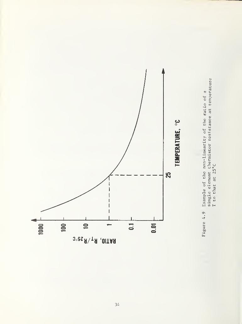
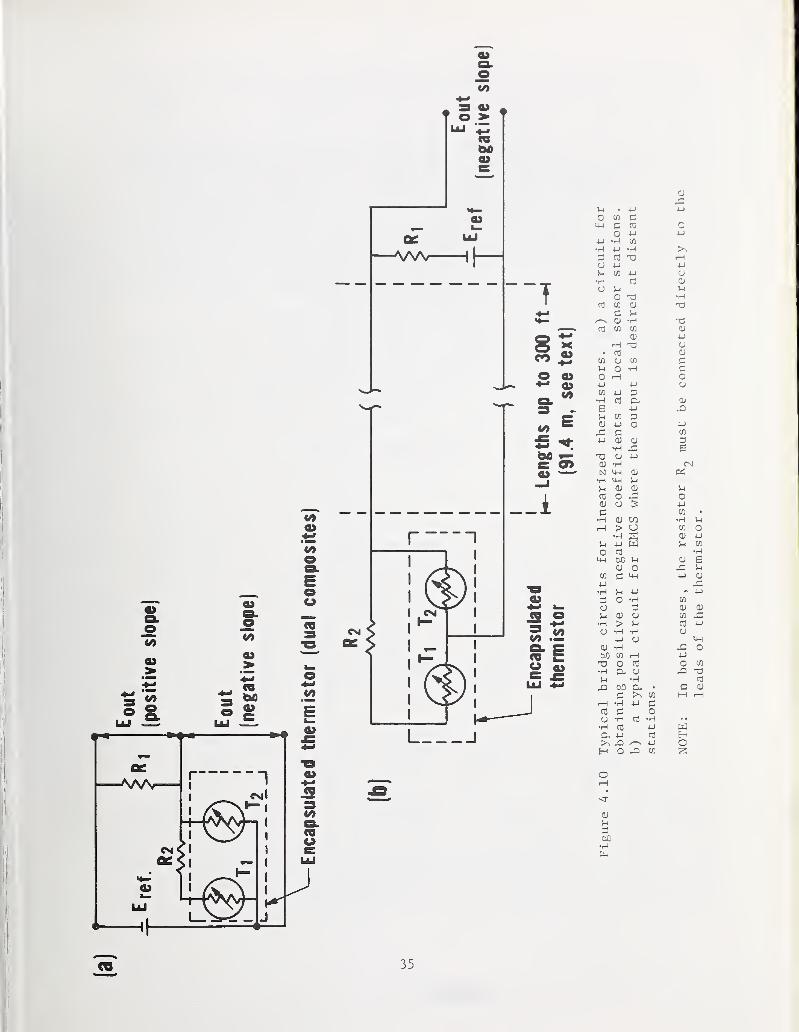


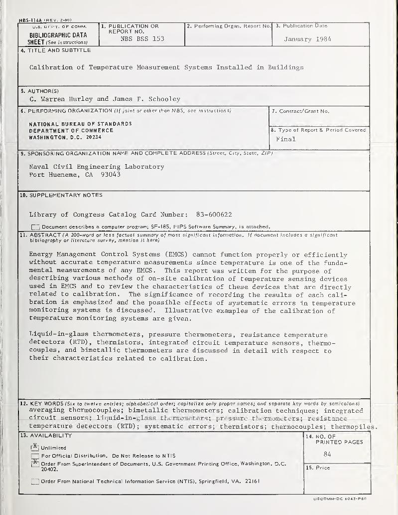


![[J. Res. Natl. Inst. Stand. Technol. 105 Ab Initio Values ... · [J. Res. Natl. Inst. Stand. Technol. 105, 667–688 (2000)] Ab Initio Values of the Thermophysical Properties of Helium](https://static.documents.pub/doc/80x56/5f2f5982e8ee966446353fc4/j-res-natl-inst-stand-technol-105-ab-initio-values-j-res-natl-inst.jpg)

![[J. Res. Natl. Inst. Stand. Technol. 106 Phase Equilibria ...nvlpubs.nist.gov/nistpubs/jres/106/6/j66wwng.pdf · [J. Res. Natl. Inst. Stand. Technol. 106, 1097–1134 (2001)] Phase](https://static.documents.pub/doc/80x56/5a8290bb7f8b9aa24f8e2214/j-res-natl-inst-stand-technol-106-phase-equilibria-j-res-natl-inst.jpg)


