42
Jessica R. Baker The Montgomery County Conference Center and HotelPenn State AE, Mechanical Rockville, MD
18
5.0 Mechanical Depth:
������������� �������� �����
Air-Side Systems
The airside mechanical system for the Montgomery County Conference Center
and Hotel consists of a combination of variable air volume and constant volume
systems served by eleven different air handling units throughout the building.
Eight of the air handling units are located in mechanical rooms throughout the
building, two rest on the hotel roof, and one is ceiling mounted in a stairway area
(See Sketch 1). Variable air volume boxes with electric reheat distribute air from
the air handling units to all spaces in the two-story conference center, as well as,
the restaurant and hotel first floor. Constant volume systems are used in the
kitchen, exercise room, pool, and guest corridors/elevator areas on each hotel
level. (Two of the three air handling units serving the kitchen area provide
makeup air to the kitchen hoods, supplying 100% outdoor air.) The following is a
list of MCCCH’s air handling units/makeup air units and the components of their
design.
Air Handling Units 1 and 2: are located in a mezzanine level mechanical roomand serve all spaces in the conference center (Variable Volume), see Sketch 1,Section A. The contents of each AHU include min/max OA dampers, re-circulated air with a variable frequency drive fan, economizer, mixing box, filter(30% ASHRAE efficiency), pre-heat coil, cooling coil, heating coil, and avariable frequency drive supply fan all mounted on a 4” high housekeeping padwith ¼” thick neoprene pads. Both air handling units are balanced at a supply aircfm of 50,000, a max OA cfm of 50,000, and a minimum OA cfm of 30,000.
Air Handling Unit 3: is also located in the mezzanine level mechanical room. Itserves the restaurant area on the main level between the conference center andhotel (Variable Volume), see Sketch 1, Section B. The contents of the AHUinclude min/max OA dampers, re-circulated air with a variable frequency drivefan, economizer, mixing box, filter (30% ASHRAE efficiency), cooling coil,heating coil, and a variable frequency drive supply fan all mounted on a 4” highhousekeeping pad with ¼” thick neoprene pads. Air handling unit 3 is balanced ata supply air cfm of 12,500, a max OA cfm of 12,500, and a minimum OA cfm of5,000.
Jessica R. Baker The Montgomery County Conference Center and HotelPenn State AE, Mechanical Rockville, MD
19
Air Handling Unit 4: is located in the mezzanine level mechanical room. Itserves the kitchen area on the main level between the conference center and hotel(Constant Volume), see Sketch 1, Section C. The contents of the AHU includemin/max OA dampers, re-circulated air, economizer, mixing box, filter (30%ASHRAE efficiency), cooling coil, heating coil, and supply fan all mounted on a4” high housekeeping pad with ¼” thick neoprene pads. Air handling unit 4 isbalanced at a supply air cfm of 9,000, a max OA cfm of 9,000, and a minimumOA cfm of 2,250.
Air Handling Unit 5: is located in a mechanical room on the main hotel level,farthest from the conference center. It serves the hotel’s first floor areas (VariableVolume), see Sketch 1, Section D. The contents of the AHU include min/maxOA dampers, re-circulated air with a variable frequency drive fan, economizer,mixing box, filter (30% ASHRAE efficiency), cooling coil, heating coil, and avariable frequency drive supply fan all mounted on a 4” high housekeeping padwith ¼” thick neoprene pads. Air handling unit 5 is balanced at a supply air cfmof 9,000, a max OA cfm of 9,000, and a minimum OA cfm of 2,250.
Air Handling Unit 6: is also located in the mechanical room on the main hotellevel, farthest from the conference center. It serves the exercise area on thehotel’s main level (Constant Volume), see Sketch 1, Section E. The contents ofthe AHU include min/max OA dampers, re-circulated air, economizer, mixingbox, filter (30% ASHRAE efficiency), cooling coil, heating coil, and supply fanall mounted on a 4” high housekeeping pad with ¼” thick neoprene pads. Airhandling unit 6 is balanced at a supply air cfm of 1,400, a max OA cfm of 1,400,and a minimum OA cfm of 350.
Air Handling Unit 7: is ceiling mounted above a stairway near the pool area onthe hotel’s main level. It exists solely to provide air to the pool area (ConstantVolume), see Sketch 1, Section F. The contents of the AHU include min/max OAdampers, re-circulated air, economizer, mixing box, filter (30% ASHRAEefficiency), preheat coil, cooling coil, heating coil, and supply fan. Additionally,the coils inside AHU 7 are coated with heresite to prevent corrosion. Airhandling unit 7 is balanced at a supply air cfm of 3,200, a max OA cfm of 3,200,and a minimum OA cfm of 1,000.
Air Handling Units 8 and 9: are both located on the roof of the hotel tower.Each provide ventilation (100% OA) to the guest corridors and elevator lobbieson hotel levels 2 through 10 (Constant Volume), see Sketch 1, Section G. Thecontents of each AHU include an economizer, filter (30% ASHRAE efficiency),preheat coil, cooling coil, heating coil, and supply fan all mounted on a factoryfinished 18” high roof curb. Air handling unit 8 is balanced at a supply air cfm of4,000, a max OA cfm of 4,000, and a minimum OA cfm of 4,000. Air handlingunit 9 is balanced at a supply air cfm of 5,000, a max OA cfm of 5,000, and aminimum OA cfm of 5,000. (There are no AHUs that serve the individual hotel
Jessica R. Baker The Montgomery County Conference Center and HotelPenn State AE, Mechanical Rockville, MD
20
guestrooms. Each of these areas is provided for by an individual vertical fan coilunit.)
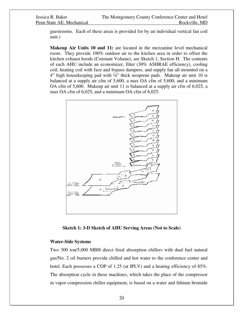
Makeup Air Units 10 and 11: are located in the mezzanine level mechanicalroom. They provide 100% outdoor air to the kitchen area in order to offset thekitchen exhaust hoods (Constant Volume), see Sketch 1, Section H. The contentsof each AHU include an economizer, filter (30% ASHRAE efficiency), coolingcoil, heating coil with face and bypass dampers, and supply fan all mounted on a4” high housekeeping pad with ¼” thick neoprene pads. Makeup air unit 10 isbalanced at a supply air cfm of 5,600, a max OA cfm of 5,600, and a minimumOA cfm of 5,600. Makeup air unit 11 is balanced at a supply air cfm of 6,025, amax OA cfm of 6,025, and a minimum OA cfm of 6,025.
Sketch 1: 3-D Sketch of AHU Serving Areas (Not to Scale)
Water-Side Systems
Two 300 ton/5,000 MBH direct fired absorption chillers with dual fuel natural
gas/No. 2 oil burners provide chilled and hot water to the conference center and
hotel. Each possesses a COP of 1.25 (at IPLV) and a heating efficiency of 85%.
The absorption cycle in these machines, which takes the place of the compressor
in vapor compression chiller equipment, is based on a water and lithium bromide
Jessica R. Baker The Montgomery County Conference Center and HotelPenn State AE, Mechanical Rockville, MD
21
solution. The two chillers/heaters are located along with the building's end
suction pumps in a mechanical room on the lower level of the conference center.
Two primary (one is stand-by), constant flow and two secondary, variable flow
end-suction pumps distribute the building’s chilled water supply. Hot water is
delivered via two (one is stand-by), constant flow end suction pumps. Two 1300
gpm cooling towers assist the absorption chillers and are located on the roof of the
hotel. This condenser water loop is driven by two constant volume end suction
pumps. In the winter months, a 1300/720 gpm plate and frame heat exchanger
operates within the condenser water loop to provide “free cooling.” Schematics
of this overall system can be found in the next section of this report.
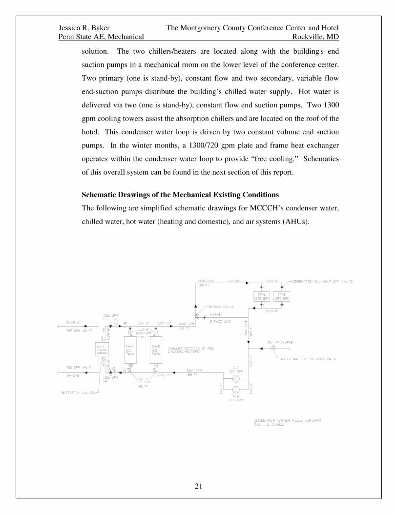
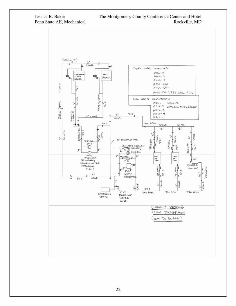
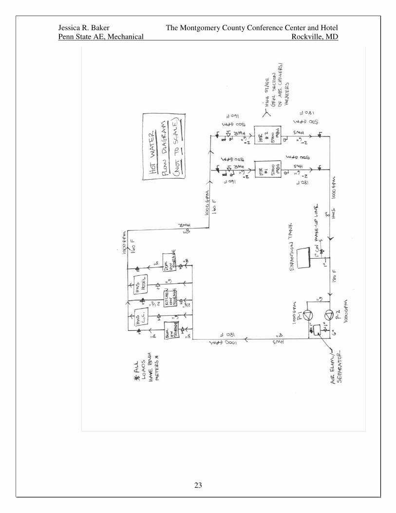
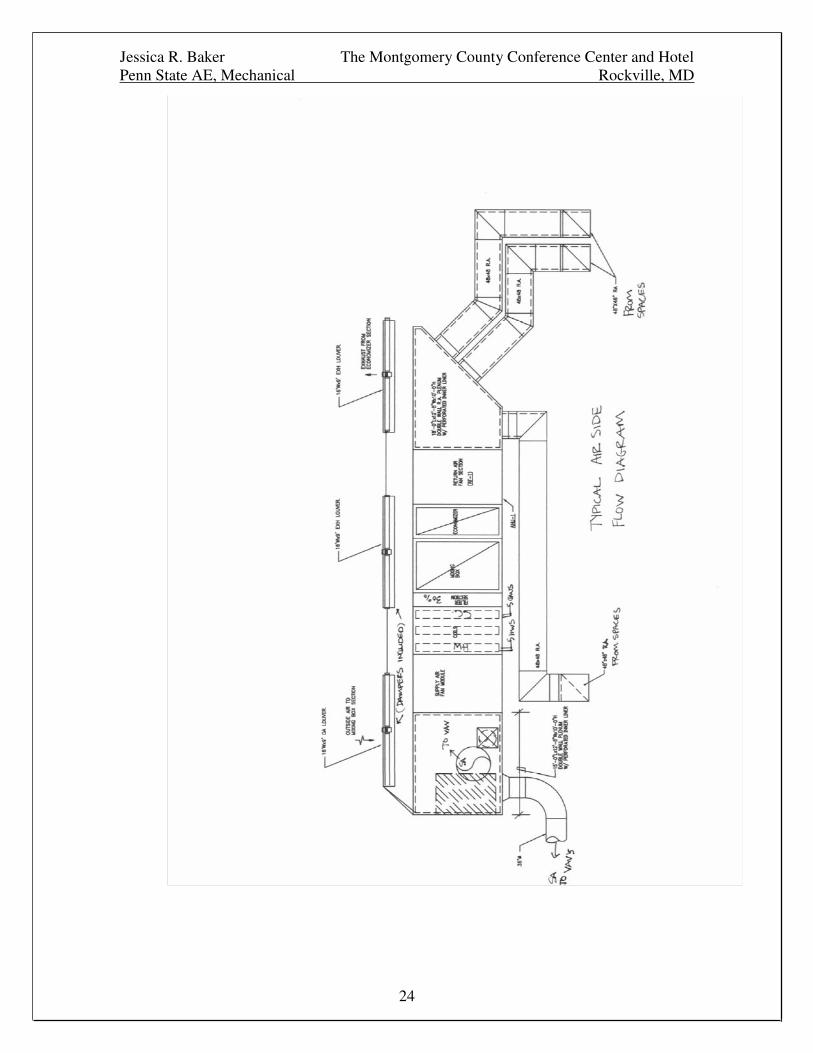
Schematic Drawings of the Mechanical Existing Conditions
The following are simplified schematic drawings for MCCCH’s condenser water,
chilled water, hot water (heating and domestic), and air systems (AHUs).
Jessica R. Baker The Montgomery County Conference Center and HotelPenn State AE, Mechanical Rockville, MD
22
Jessica R. Baker The Montgomery County Conference Center and HotelPenn State AE, Mechanical Rockville, MD
23
Jessica R. Baker The Montgomery County Conference Center and HotelPenn State AE, Mechanical Rockville, MD
24
Jessica R. Baker The Montgomery County Conference Center and HotelPenn State AE, Mechanical Rockville, MD
25
Schedule of Operation
The hours of operation for MCCCH were assumed to be different between the
hotel and conference center portions of the building. The hotel was designed to
be operating 24-hours/day, 365 days/year. The conference center was assumed to
have the following operation schedule:
Monday-Thursday 7:00AM to 7:00PM
Friday-Sunday 6:00AM to 12:00PM
It was also assumed that both the hotel and conference center would be open for
events on holidays, etc.
Outdoor Design Conditions
Climatic Design Conditions for 1,459 locations throughout the United States,
Canada, and around the world are listed in Chapter 27 of the ASHRAE
Fundamentals. This chapter gives a table containing design information
pertaining to heating and cooling in buildings. For the MCCCH project, the
design condition data from the Washington, District of Columbia location was
used and is as follows:
Summer Conditions (ASHRAE 1%) at Atmospheric Pressure in D.C.
Dry Bulb Temperature: 95 �F
Coincident Wet Bulb Temperature: 76 �F
Summer Daily Range: 16.6 �F
Winter Conditions (ASHRAE 99%) at Atmospheric Pressure in D.C.
Dry Bulb Temperature: 15 �F
Coincident Wet Bulb Temperature: 12.2 �F
Indoor Design Conditions
The indoor design conditions were specified in MCCCH’s project documents /
specifications and are the following:
Dry Bulb Temperature: 72 �F
Relative Humidity: 50%
Jessica R. Baker The Montgomery County Conference Center and HotelPenn State AE, Mechanical Rockville, MD
26
(MCCCH’s spaces were to be kept within an approximate 1.5 �F range of this set
point.)
Air Handling Unit Operation
Description
The exact specifications and areas served by the different air handling units
throughout MCCCH have already been mentioned above. However, the way in
which the AHUs operate has not yet been analyzed.
Most of the air handling units throughout the building supply 50-52 degree F air
to the different spaces. All units, except the MAUs in the kitchen area, have
outdoor air (OA) dampers running on an economizer cycle between 100% OA
and the minimum calculated ventilation air rate. The units also contain
centrifugal supply and return fans that slightly pressurize the building spaces.
This pressurization was done in such a way that a special smoke containment
system could be installed throughout the conference center portion of the
building. Smoke zones and fan shut-off and start-up sequences were completely
simulated and implemented. Variable speed controls were used on all the
different units as well (see AHU descriptions above). Most units do not
incorporate the use of ducted returns.
Sequence of Operation
The air handling units in the hotel portion of the building operate almost
constantly throughout the year while the conference center units operate on an
occupied/unoccupied basis. Normally, on days that the conference center will be
occupied, the AHUs that serve the conference center will begin a warm-up
approximately one hour prior to the arrival of people. Most of the time, the
building’s OA dampers will be closed throughout this warm-up and the building
will re-circulate its own air (while cooling or heating if the need be) until the
return air reaches a “cool enough” or “warm enough” set point, (the exact set
point was unknown for this report). At the time that people begin to arrive at the
conference center, the exhaust fans will start relieving some of the building’s
Jessica R. Baker The Montgomery County Conference Center and HotelPenn State AE, Mechanical Rockville, MD
27
indoor air while the OA dampers open to provide proper ventilation. At this
point, the economizer cycle will be in full use and the OA will be used to cool
when its temperature is less than the “cool enough” set point. At higher OA
temperatures, the OA dampers will again close and the building’s AHUs will take
care of the building’s cooling load. Temperature sensors and air mixing sensors
control the economizer cycle and OA dampers. The mechanical cooling will
provide 50-52 degree F air at the AHUs. Once this air reaches the VAV boxes or
the supply diffusers, it is normally somewhere around 55 degrees F. When a
space becomes unoccupied, terminal reheat is used throughout the conference
center spaces until certain systems shut off.
Safeties that exist for the building’s air-side system include pre-heating and
heating coil bypass and recirculation pumps in order to avoid the freezing-up of
any AHU coils. Smoke detectors and sensors/fire dampers were installed
throughout the ductwork and major air-side equipment in the building. These
devices play into the smoke containment system, another safety, which was
mentioned earlier in the report.
Direct-Fired Absorption Chiller Operation
Description
The Montgomery County Conference Center and Hotel’s two direct-fired
absorption chillers run mainly on natural gas but contain duel fuel burners for
back-up use with No. 2 fuel oil. Each possesses a COP of 1.25 (at IPLV) and a
heating efficiency of 85%. The absorption cycle in these machines, which takes
the place of the compressor in traditional chiller equipment, is based on a water
and lithium bromide solution.
Sequence of Operation
With a hotel, the demand for hot water is almost always constant. Therefore,
normally, at least one absorption chiller in MCCCH is operating at all times.
(During the day, people in the hotel need hot water along with the hotel’s kitchen
and laundry areas. At night, hotel guests demand even more hot water while the
Jessica R. Baker The Montgomery County Conference Center and HotelPenn State AE, Mechanical Rockville, MD
28
laundry also continues.) However, this is ok due to the fact that the hotel also
needs cooling around the clock. With at least one absorption chiller running at all
times, both heating and cooling will be produced at a constant rate. Most of these
energies are used up by just the hotel. As the conference center’s occupancy
changes, MCCCH’s second absorption chiller will turn on and off to provide the
necessary treatment in that area of the building.
When the heating and cooling loads/demands do not completely match between
the building spaces and absorption machines, thermal storage is implemented.
The usual case is that the building demands more cooling/chilled water than hot
water. For this situation, MCCCH’s design engineers installed hot water holding
tanks for the different areas of the building that are likely to demand a lot of hot
water all at once (kitchen, hotel, and laundry).
When chilled or hot water is needed in either portion of the building, the
respective pumps will turn on and begin pumping water to the particular area.
One of the absorption chillers/heaters is likely to already be running and will
begin supplying these pumps. (Chiller/Heater supply water temperatures would
be based on (OA) controls set throughout the building’s AHUs and other
mechanical equipment.) Flow sensors/meters will monitor all flows through the
chillers/heaters and pumps. If any problems occur, valves will be shut and the
pumps turned off prior to any damage. Normally, the chillers/heaters are kept
running as they don’t like to be quickly shut down and then turned on again. If a
severe problem would exist with the chillers/heaters, they would be shut down
immediately. In an additional effort to avoid the need for a quick shut down,
several stand-by pumps were also installed and wired to start-up at the failure of
any lead pumps.
Jessica R. Baker The Montgomery County Conference Center and HotelPenn State AE, Mechanical Rockville, MD
29
������������� �����������
Introduction / Redesign Criteria and Objectives
The idea behind the mechanical system redesign of MCCCH was to improve the
system’s overall performance while also lowering its life-cycle cost. The redesign
process followed a general outline put forth by the Pennsylvania State
University’s Architectural Engineering Department. “All modifications and
changes related to the original building design and construction methodology
were solely for the purpose of academic development. Changes and discrepancies
in no way imply that the original design contained errors or was flawed. Different
assumptions, code references, requirements, and methodologies were incorporated
into the redesign; therefore, investigation results varied from the original design”
(P.S.U. A.E. Thesis E-studio Disclaimer).
One major goal of the redesign involved improving matters that directly affected
the building’s owner and surrounding environment. As stated before, the main
goal behind the redesign was to decrease the building mechanical and related
systems’ life-cycle costs. (Lower building system first costs were not primary
objectives of the redesign as they were not considered driving factors for success.
However, in the end, the overall redesign did reduce most system first costs.)
One way in which all of this was attempted entailed decreasing the building’s
annual energy consumption. By doing this, the monthly/annual bills for the
facility/building owner were decreased. This also resulted in a more
environmentally friendly building. Less energy usage converted directly into less
fossil fuel use, and less fossil fuel usage meant fewer emissions by both the
building’s electricity supplier and the building itself. In an area like Washington
D.C. and Baltimore, such savings would be very appealing to building owners as
utility rates can be extremely lofty. The fact that the redesign proved beneficial to
the environment created even further encouragement.
Jessica R. Baker The Montgomery County Conference Center and HotelPenn State AE, Mechanical Rockville, MD
30
Another goal for the successful redesign of MCCCH’s mechanical system
involved providing an improved, clear, and concise control/operation strategy for
any altered or new building systems. This acted as a check for successful system
implementation while it also highlighted additional benefits to the owner. The
clearer the control and operation of the building systems, the easier the redesign
would be to maintain for building operators.
A final objective for the redesign of MCCCH included providing a clear design
while not losing any of the beneficial aspects of the building’s original systems.
Any changes made to the original building systems were checked for negative
influences and all processes of review were based upon an “apples to apples”
comparison.
Problem Statement / Solution Overview / Design Options and Considerations
The main mechanical system alteration consisted of selecting and designing an
optimized chiller plant for MCCCH. The application of latent thermal ice storage
was implemented throughout the design process of the optimum chiller plant
configuration.
MCCCH’s current chilling plant contains two direct-fired (natural gas) absorption
chillers that were essentially thrown into the building’s mechanical system and
never optimized. The original mechanical design incorporated the use of two
vapor-compression machines but, the building’s absorption chilling machines
were offered to the owner at a very low first cost. Because of this, the original
design of the building’s chiller plant was changed to include the absorption
machines and not the vapor-compression machines. To my knowledge, the
affects of this modification on the building’s operating/life-cycle costs were never
really studied. (At the time of design, the building’s first costs were of main
concern.)
Therefore, for my thesis project, this absorption chilling plant configuration was
tested against several other central cooling plant designs in order to determine and
Jessica R. Baker The Montgomery County Conference Center and HotelPenn State AE, Mechanical Rockville, MD
31
select the most favorable chiller plant design for MCCCH. One comparative
design arrangement involved vapor-compression (electric), water-cooled chillers
coupled with hot water boilers (and later, thermal storage). Another comparison
consisted of a hybrid absorption (natural gas)/vapor-compression (electric) plant
designed for chilled and heating/domestic hot water production. The optimum
chiller plant configuration was selected based upon each working arrangement’s
energy consumption, life-cycle cost, and simplicity of control.
From there, a preliminary design of the most favorable plant type was sized and
created for MCCCH. This plant was then further optimized between four specific
chiller plant equipment manufacturers; Carrier, McQuay, Trane, and York.
Again, the optimum was selected based upon each arrangement/manufacturer’s
respective energy consumption, life-cycle cost, and simplicity of control for
MCCCH.
Finally, the addition of a cool thermal storage system to the optimum chiller plant
design was studied. Several different types of cool thermal storage were
considered including daily full - chilled water storage, daily full - glycol ice
storage, daily partial/load leveling - chilled water storage, daily partial/load
leveling – glycol ice storage, and daily partial/demand limiting – glycol ice
storage. Cost comparisons were made and feasibility studied in order to
determine the best cool thermal storage design for MCCCH.
The most favorable cool thermal storage plant was then sized/designed and
coupled with a downsized version of MCCCH’s optimum chiller plant type
(determined initially). This upgraded central chilling plant with cool thermal
storage was then compared to the building’s original optimum plant using
respective energy consumption, life-cycle cost, and simplicity of control.
Between the two plants, the paramount was selected and recommended as the
final design for MCCCH’s central chilling plant.
Jessica R. Baker The Montgomery County Conference Center and HotelPenn State AE, Mechanical Rockville, MD
32
All central chilling plant comparisons utilized “up to date” utility rates for the
building’s geographic location as the rates played a major role in selecting the
optimum plant for MCCCH. Also, the final design recommendation was fully
compared to MCCCH’s original cooling plant design.
Justification
Improved economics and lessened environmental impact were two of the
expected outcomes of the redesign for the Montgomery County Conference
Center and Hotel. As a result of optimizing the building’s central chilling plant,
the building’s life-cycle costs were greatly decreased and less on-site energy was
used.
However, to clarify, the reduction in on-site energy usage only occurred due to a
switch from natural gas to electric driven chilling machines and will only
positively affect the building’s immediate environment (as there are no longer
direct emissions coming from the building’s natural gas usage). Despite the fact
that electric chillers have higher efficiencies than natural gas absorption
machines, generation and transmission losses make electricity highly inefficient
(only 28% efficient to be exact). Therefore, MCCCH’s final redesign will most
likely have a negative affect on the earth’s environment as a whole; given that the
amount of indirect emissions from electricity usage far exceeds the amount of
emissions produced by natural gas usage (for this particular building application).
In effect, the overall redesign of MCCCH’s central chilling plant can only really
take credit for lowering the building’s life-cycle costs.
Coordination and Integration
The greatest coordination issue of the redesign involved the rearranging and
addition of major equipment in the building’s central chilling/heating plant.
Several pieces of new equipment were added to the building. Other existing
equipment was kept and relocated, or simply replaced. Either way, space was an
Jessica R. Baker The Montgomery County Conference Center and HotelPenn State AE, Mechanical Rockville, MD
33
issue. Therefore, throughout the redesign, all areas allocated as mechanical rooms
were precisely laid out in order to fit all equipment properly.
Another large integration issue entailed maintaining the building’s superficial
appearance throughout the redesign of the mechanical system. Several large
pieces of equipment ended up being placed on or around the exterior of the
building. However, these changes in no way detracted from the building itself.
Much special care was taken to maintain MCCCH’s architectural integrity.
Selection of Chiller Plant Type / Initial Chiller Plant Optimization andDesign
As stated before, MCCCH’s original central chilling plant consisted of 2-300 ton,
direct-fired absorption chillers that provided the building with all of its chilled and
heating/domestic hot water. Both chillers were powered by natural gas and also
had the capability of using #2 fuel oil as backup.
Again, as mentioned earlier, these two absorption machines were essentially
“thrown into” the building’s mechanical design at the last minute. Large amounts
of first cost savings for the owner played a major role in the hasty decision to
change the design of the building’s central chilling plant. However, there was
some question in my mind as to whether or not this type of central chilling plant
was best for this particular application. Was this the most energy efficient design
and were the operating costs of this plant going to be competitive enough with
those that could be produced by other types of central chilling plants given
MCCCH’s geographic area and specific utility rates? Did the owner know the
implications of this last minute decision and how it may affect his building
operation costs throughout the life of the building despite the very low initial
costs? Therefore, my chiller plant optimization process began.
My first step involved developing a very thorough load/energy
analysis/simulation of the Montgomery County Conference Center and Hotel
using Carrier’s Hourly Analysis Program (HAP) and the building’s absorption
Jessica R. Baker The Montgomery County Conference Center and HotelPenn State AE, Mechanical Rockville, MD
34
cooling/heating central plant. This had to be done because no load or energy
calculations could be obtained from the building’s design engineers. Therefore,
this step was crucial as all the modeling had to be extremely specific in order to
produce accurate and useable output.
Obtaining and using the correct utility rates (electric and natural gas) for the
building was one very important key to properly modeling MCCCH in Carrier’s
HAP. These rates would not only be used for modeling the absorption plant but
for all other plant simulations and comparisons throughout the entire chiller plant
optimization process. Both the electric and natural gas rate structures used in the
modeling of MCCCH can be found in Appendix A.
Applying the correct building occupancy and thermostat schedules was also very
key to the HAP modeling process. However, all of the building schedules utilized
for this project will be covered later in the ‘cool thermal storage system design’
section of this report. (The same schedules were used for all central chiller plant
configurations and simulations.)
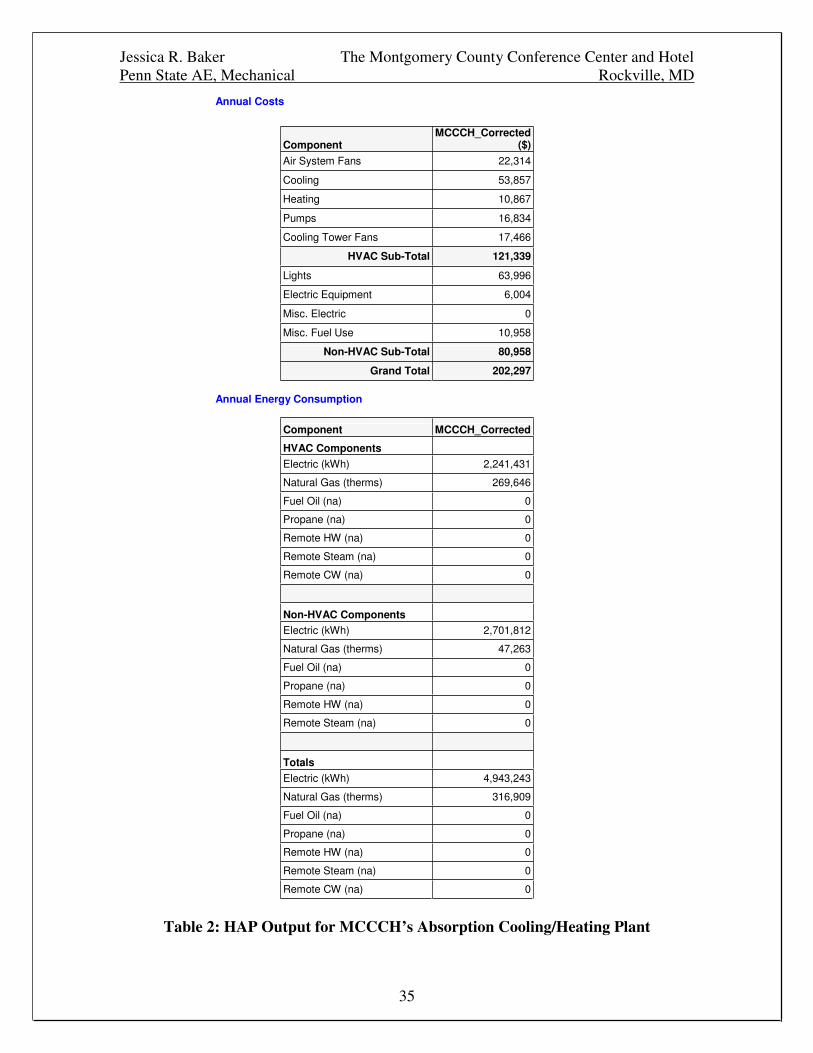
Thus, the HAP calculations for MCCCH’s central absorption chilling/heating
plant were performed and the annual operating costs and energy consumption can
be seen below in the HAP Table 2. The full HAP output for this plant can be
viewed in Appendix C.
Jessica R. Baker The Montgomery County Conference Center and HotelPenn State AE, Mechanical Rockville, MD
35
Annual Costs
ComponentMCCCH_Corrected
($)
Air System Fans 22,314
Cooling 53,857
Heating 10,867
Pumps 16,834
Cooling Tower Fans 17,466
HVAC Sub-Total 121,339
Lights 63,996
Electric Equipment 6,004
Misc. Electric 0
Misc. Fuel Use 10,958
Non-HVAC Sub-Total 80,958
Grand Total 202,297
Annual Energy Consumption
Component MCCCH_Corrected
HVAC ComponentsElectric (kWh) 2,241,431
Natural Gas (therms) 269,646
Fuel Oil (na) 0
Propane (na) 0
Remote HW (na) 0
Remote Steam (na) 0
Remote CW (na) 0
Non-HVAC ComponentsElectric (kWh) 2,701,812
Natural Gas (therms) 47,263
Fuel Oil (na) 0
Propane (na) 0
Remote HW (na) 0
Remote Steam (na) 0
TotalsElectric (kWh) 4,943,243
Natural Gas (therms) 316,909
Fuel Oil (na) 0
Propane (na) 0
Remote HW (na) 0
Remote Steam (na) 0
Remote CW (na) 0
Table 2: HAP Output for MCCCH’s Absorption Cooling/Heating Plant
Jessica R. Baker The Montgomery County Conference Center and HotelPenn State AE, Mechanical Rockville, MD
36
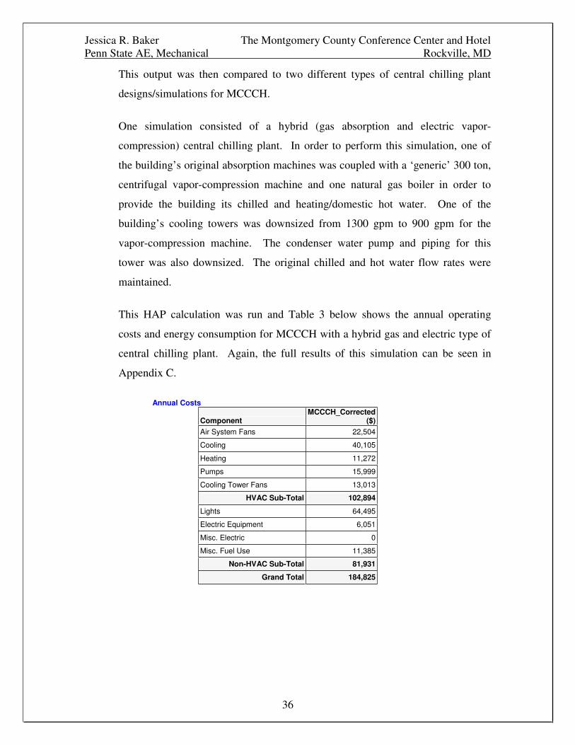
This output was then compared to two different types of central chilling plant
designs/simulations for MCCCH.
One simulation consisted of a hybrid (gas absorption and electric vapor-
compression) central chilling plant. In order to perform this simulation, one of
the building’s original absorption machines was coupled with a ‘generic’ 300 ton,
centrifugal vapor-compression machine and one natural gas boiler in order to
provide the building its chilled and heating/domestic hot water. One of the
building’s cooling towers was downsized from 1300 gpm to 900 gpm for the
vapor-compression machine. The condenser water pump and piping for this
tower was also downsized. The original chilled and hot water flow rates were
maintained.
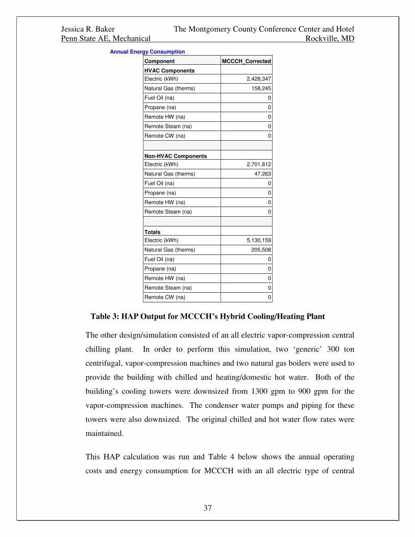
This HAP calculation was run and Table 3 below shows the annual operating
costs and energy consumption for MCCCH with a hybrid gas and electric type of
central chilling plant. Again, the full results of this simulation can be seen in
Appendix C.
Annual Costs
ComponentMCCCH_Corrected
($)Air System Fans 22,504
Cooling 40,105
Heating 11,272
Pumps 15,999
Cooling Tower Fans 13,013
HVAC Sub-Total 102,894
Lights 64,495
Electric Equipment 6,051
Misc. Electric 0
Misc. Fuel Use 11,385
Non-HVAC Sub-Total 81,931
Grand Total 184,825
Jessica R. Baker The Montgomery County Conference Center and HotelPenn State AE, Mechanical Rockville, MD
37
Annual Energy Consumption
Component MCCCH_Corrected
HVAC Components
Electric (kWh) 2,428,347
Natural Gas (therms) 158,245
Fuel Oil (na) 0
Propane (na) 0
Remote HW (na) 0
Remote Steam (na) 0
Remote CW (na) 0
Non-HVAC Components
Electric (kWh) 2,701,812
Natural Gas (therms) 47,263
Fuel Oil (na) 0
Propane (na) 0
Remote HW (na) 0
Remote Steam (na) 0
TotalsElectric (kWh) 5,130,159
Natural Gas (therms) 205,508
Fuel Oil (na) 0
Propane (na) 0
Remote HW (na) 0
Remote Steam (na) 0
Remote CW (na) 0
Table 3: HAP Output for MCCCH’s Hybrid Cooling/Heating Plant
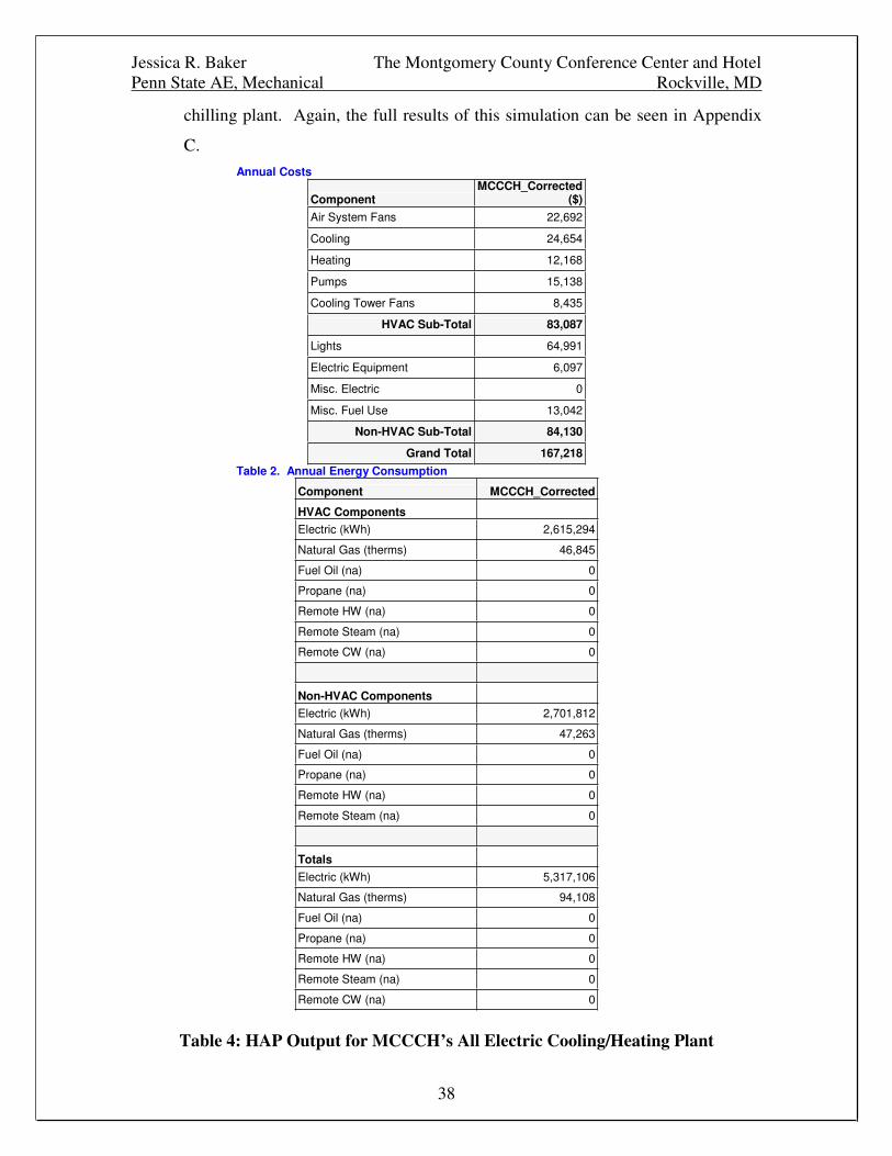
The other design/simulation consisted of an all electric vapor-compression central
chilling plant. In order to perform this simulation, two ‘generic’ 300 ton
centrifugal, vapor-compression machines and two natural gas boilers were used to
provide the building with chilled and heating/domestic hot water. Both of the
building’s cooling towers were downsized from 1300 gpm to 900 gpm for the
vapor-compression machines. The condenser water pumps and piping for these
towers were also downsized. The original chilled and hot water flow rates were
maintained.
This HAP calculation was run and Table 4 below shows the annual operating
costs and energy consumption for MCCCH with an all electric type of central
Jessica R. Baker The Montgomery County Conference Center and HotelPenn State AE, Mechanical Rockville, MD
38
chilling plant. Again, the full results of this simulation can be seen in Appendix
C.
Annual Costs
ComponentMCCCH_Corrected
($)
Air System Fans 22,692
Cooling 24,654
Heating 12,168
Pumps 15,138
Cooling Tower Fans 8,435
HVAC Sub-Total 83,087
Lights 64,991
Electric Equipment 6,097
Misc. Electric 0
Misc. Fuel Use 13,042
Non-HVAC Sub-Total 84,130
Grand Total 167,218
Table 2. Annual Energy Consumption
Component MCCCH_Corrected
HVAC ComponentsElectric (kWh) 2,615,294
Natural Gas (therms) 46,845
Fuel Oil (na) 0
Propane (na) 0
Remote HW (na) 0
Remote Steam (na) 0
Remote CW (na) 0
Non-HVAC ComponentsElectric (kWh) 2,701,812
Natural Gas (therms) 47,263
Fuel Oil (na) 0
Propane (na) 0
Remote HW (na) 0
Remote Steam (na) 0
Totals
Electric (kWh) 5,317,106
Natural Gas (therms) 94,108
Fuel Oil (na) 0
Propane (na) 0
Remote HW (na) 0
Remote Steam (na) 0
Remote CW (na) 0
Table 4: HAP Output for MCCCH’s All Electric Cooling/Heating Plant
Jessica R. Baker The Montgomery County Conference Center and HotelPenn State AE, Mechanical Rockville, MD
39
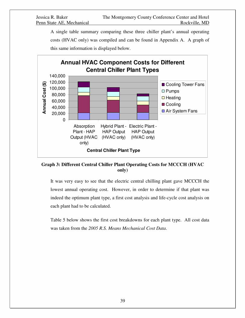
A single table summary comparing these three chiller plant’s annual operating
costs (HVAC only) was compiled and can be found in Appendix A. A graph of
this same information is displayed below.
Annual HVAC Component Costs for DifferentCentral Chiller Plant Types
020,00040,00060,00080,000
100,000120,000140,000
AbsorptionPlant - HAP
Output (HVAConly)
Hybrid Plant -HAP Output(HVAC only)
Electric Plant -HAP Output(HVAC only)
Central Chiller Plant Type
An
nu
alC
ost
($)
Cooling Tower Fans
Pumps
Heating
Cooling
Air System Fans
Graph 3: Different Central Chiller Plant Operating Costs for MCCCH (HVAConly)
It was very easy to see that the electric central chilling plant gave MCCCH the
lowest annual operating cost. However, in order to determine if that plant was
indeed the optimum plant type, a first cost analysis and life-cycle cost analysis on
each plant had to be calculated.
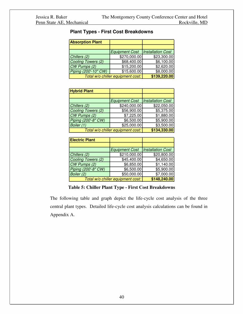
Table 5 below shows the first cost breakdowns for each plant type. All cost data
was taken from the 2005 R.S. Means Mechanical Cost Data.
Jessica R. Baker The Montgomery County Conference Center and HotelPenn State AE, Mechanical Rockville, MD
40
Plant Types - First Cost Breakdowns
Absorption Plant
Equipment Cost Installation CostChillers (2) $270,000.00 $23,300.00Cooling Towers (2) $68,400.00 $6,100.00CW Pumps (2) $15,200.00 $2,620.00Piping (200'-10" CW) $15,600.00 $8,000.00
Total w/o chiller equipment cost: $139,220.00
Hybrid Plant
Equipment Cost Installation CostChillers (2) $240,000.00 $22,050.00Cooling Towers (2) $56,900.00 $5,375.00CW Pumps (2) $7,225.00 $1,880.00Piping (200'-8" CW) $6,500.00 $5,900.00Boiler (1) $25,000.00 $3,500.00
Total w/o chiller equipment cost: $134,330.00
Electric Plant
Equipment Cost Installation CostChillers (2) $210,000.00 $20,800.00Cooling Towers (2) $45,400.00 $4,650.00CW Pumps (2) $6,850.00 $1,140.00Piping (200'-8" CW) $6,500.00 $5,900.00Boiler (2) $50,000.00 $7,000.00
Total w/o chiller equipment cost: $148,240.00
Table 5: Chiller Plant Type - First Cost Breakdowns
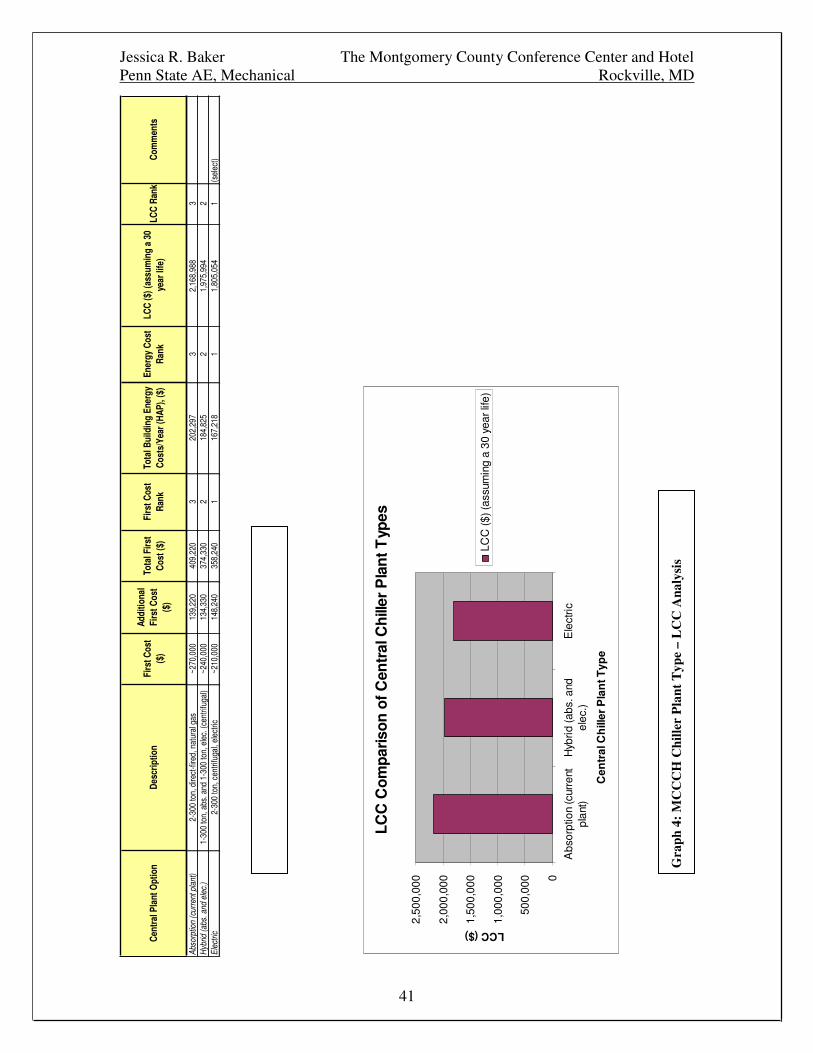
The following table and graph depict the life-cycle cost analysis of the three
central plant types. Detailed life-cycle cost analysis calculations can be found in
Appendix A.
Jessica R. Baker The Montgomery County Conference Center and HotelPenn State AE, Mechanical Rockville, MD
41
Cent
ralP
lant
Opt
ion
Desc
riptio
nFi
rstC
ost
($)
Addi
tiona
lFi
rstC
ost
($)
Tota
lFirs
tCo
st($
)Fi
rstC
ost
Rank
Tota
lBui
ldin
gEn
ergy
Cost
s/Ye
ar(H
AP),
($)
Ener
gyCo
stRa
nkLC
C($
)(as
sum
ing
a30
year
life)
LCC
Rank
Com
men
ts
Abso
rptio
n(c
urre
ntpl
ant)
2-30
0to
n,di
rect
-fire
d,na
tura
lgas
~270
,000
139,
220
409,
220
320
2,29
73
2,16
8,98
83
Hyb
rid(a
bs.a
ndel
ec.)
1-30
0to
n,ab
s.an
d1-
300
ton,
elec
.(ce
ntrif
ugal
)~2
40,0
0013
4,33
037
4,33
02
184,
825
21,
975,
994
2El
ectri
c2-
300
ton,
cent
rifug
al,e
lect
ric~2
10,0
0014
8,24
035
8,24
01
167,
218
11,
805,
054
1(s
elec
t)
LCC
Com
paris
onof
Cen
tral
Chi
ller
Pla
ntT
ypes
0
500,
000
1,00
0,00
0
1,50
0,00
0
2,00
0,00
0
2,50
0,00
0
Abs
orpt
ion
(cur
rent
plan
t)H
ybrid
(abs
.and
elec
.)E
lect
ric
Cen
tral
Ch
iller
Pla
ntT
ype
LCC($)
LCC
($)(
assu
min
ga
30ye
arlif
e)
Gra
ph4:
MC
CC
HC
hille
rP
lant
Typ
e–
LC
CA
naly
sis
Jessica R. Baker The Montgomery County Conference Center and HotelPenn State AE, Mechanical Rockville, MD
42
From the above calculations, it was very apparent that an electric central chilling
plant design of 2-300 ton centrifugal, vapor-compression chillers coupled with 2
natural gas boilers, was the most economical for the Montgomery County
Conference Center and Hotel. Its L.C.C. was much lower than the other two plant
options; one being the original plant design! However, before calculating the
total overall savings, further optimization was performed.
Further Chiller Plant Optimization and Design According to ChillerManufacturers
In an effort to further optimize MCCCH’s central chilling plant design, Pacific
Gas and Electric Company’s CoolTools-Chilled Water Plant Design and
Specification Guide was consulted. In there, a process for optimizing among the
many different chiller manufacturers was found. The following is CoolTools’
recommended optimization approach:
- Calculate or estimate the required plant total tonnage
- Pick a short list of vendors based on past experience
and local representation
- Request chiller bids based on a performance
specification
- Adjust bids for other first cost impacts
- Estimate the energy usage of options with a detailed
computer model of the building/plant
- Calculate life cycle cost differences between options
- Select the chiller option with the lowest LCC
Therefore, the CoolTools approach was very close to what was done for the initial
optimization of MCCCH’s central cooling plant design. So, for this part of the
optimization between different chiller manufacturers:
- The plant tonnage had already been calculated
- The list of vendors included Carrier, McQuay, Trane,
and York
Jessica R. Baker The Montgomery County Conference Center and HotelPenn State AE, Mechanical Rockville, MD
43
- Representatives from each manufacturer were contacted
and chiller models and bids were requested (each
manufacturer was to size and price 2-300 ton
centrifugal chillers and send operating information)
- The bids were received and were corrected for first cost
impacts (all models were received as well as one
additional option – one McQuay 600 ton chiller (double
compression) which was also analyzed)
- MCCCH’s energy usage and operating costs for each
chiller manufacturer’s cooling plant were simulated by
using Carrier’s HAP.
- The life-cycle cost of MCCCH’s central cooling plant
was calculated for each manufacturer and compared.
- Finally, the manufacturer/cooling plant with the lowest
L.C.C. was selected.
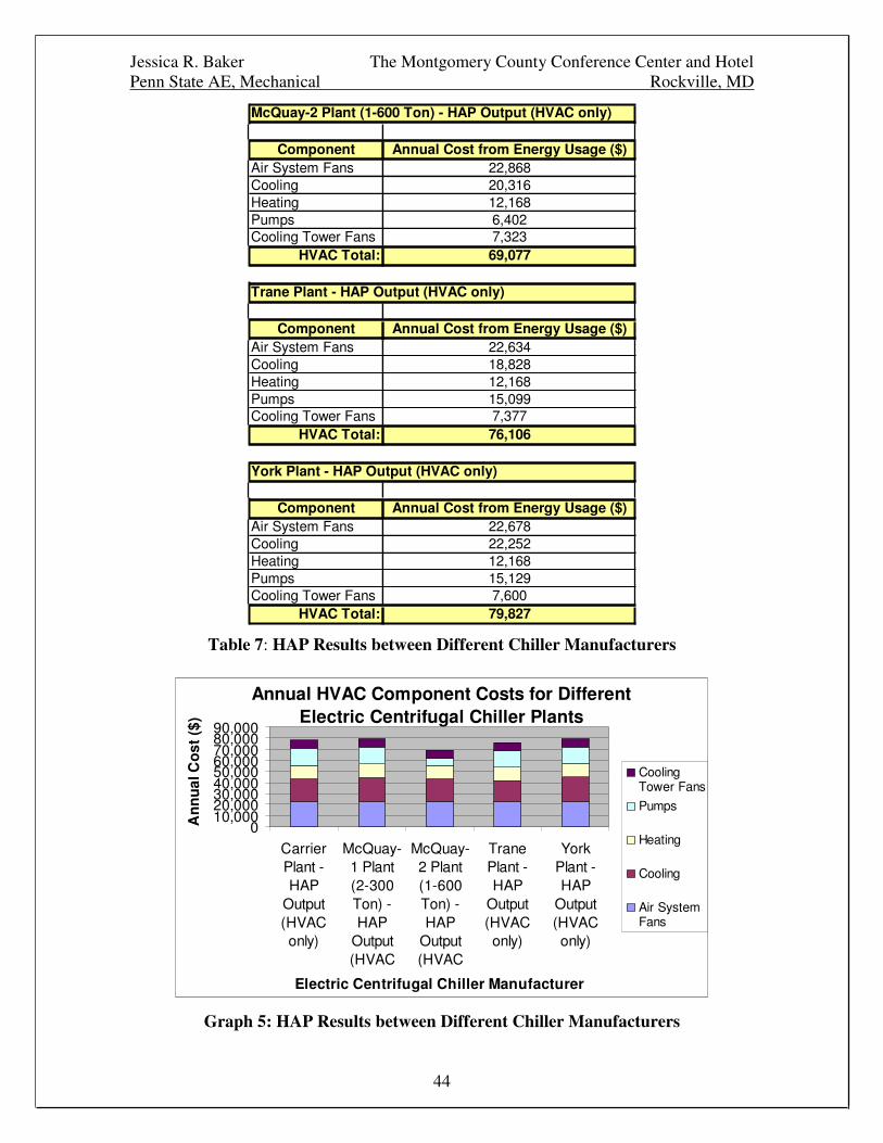
The following table and graph depict the HAP output/operating costs for each
chiller manufacturer’s cooling plant in MCCCH. Only HVAC operating costs
were examined. Full HAP results for each chiller manufacturer’s cooling plant in
MCCCH can be found in Appendix C.
Carrier Plant - HAP Output (HVAC only)
Component Annual Cost from Energy Usage ($)Air System Fans 22,659Cooling 20,744Heating 12,168Pumps 15,116Cooling Tower Fans 7,502
HVAC Total: 78,189
McQuay-1 Plant (2-300 Ton) - HAP Output (HVAC only)
Component Annual Cost from Energy Usage ($)Air System Fans 22,674Cooling 21,874Heating 12,168Pumps 15,125Cooling Tower Fans 7,576
HVAC Total: 79,417
Jessica R. Baker The Montgomery County Conference Center and HotelPenn State AE, Mechanical Rockville, MD
44
McQuay-2 Plant (1-600 Ton) - HAP Output (HVAC only)
Component Annual Cost from Energy Usage ($)Air System Fans 22,868Cooling 20,316Heating 12,168Pumps 6,402Cooling Tower Fans 7,323
HVAC Total: 69,077
Trane Plant - HAP Output (HVAC only)
Component Annual Cost from Energy Usage ($)Air System Fans 22,634Cooling 18,828Heating 12,168Pumps 15,099Cooling Tower Fans 7,377
HVAC Total: 76,106
York Plant - HAP Output (HVAC only)
Component Annual Cost from Energy Usage ($)Air System Fans 22,678Cooling 22,252Heating 12,168Pumps 15,129Cooling Tower Fans 7,600
HVAC Total: 79,827
Table 7: HAP Results between Different Chiller Manufacturers
Annual HVAC Component Costs for DifferentElectric Centrifugal Chiller Plants
010,00020,00030,00040,00050,00060,00070,00080,00090,000
CarrierPlant -HAP
Output(HVAConly)
McQuay-1 Plant(2-300Ton) -HAP
Output(HVAC
McQuay-2 Plant(1-600Ton) -HAP
Output(HVAC
TranePlant -HAP
Output(HVAConly)
YorkPlant -HAP
Output(HVAConly)
Electric Centrifugal Chiller Manufacturer
An
nu
alC
ost
($)
CoolingTower Fans
Pumps
Heating
Cooling
Air SystemFans
Graph 5: HAP Results between Different Chiller Manufacturers
Jessica R. Baker The Montgomery County Conference Center and HotelPenn State AE, Mechanical Rockville, MD
45
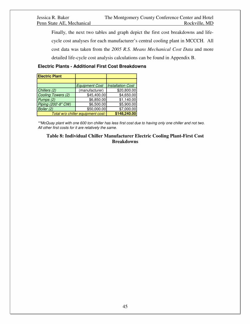
Finally, the next two tables and graph depict the first cost breakdowns and life-
cycle cost analyses for each manufacturer’s central cooling plant in MCCCH. All
cost data was taken from the 2005 R.S. Means Mechanical Cost Data and more
detailed life-cycle cost analysis calculations can be found in Appendix B.
Electric Plants - Additional First Cost Breakdowns
Electric Plant
Equipment Cost Installation CostChillers (2) (manufacturer) $20,800.00Cooling Towers (2) $45,400.00 $4,650.00Pumps (2) $6,850.00 $1,140.00Piping (200'-8" CW) $6,500.00 $5,900.00Boiler (2) $50,000.00 $7,000.00
Total w/o chiller equipment cost: $148,240.00
**McQuay plant with one 600 ton chiller has less first cost due to having only one chiller and not two.All other first costs for it are relatively the same.
Table 8: Individual Chiller Manufacturer Electric Cooling Plant-First CostBreakdowns
Jessica R. Baker The Montgomery County Conference Center and HotelPenn State AE, Mechanical Rockville, MD
46
Man
ufac
ture
rD
escr
iptio
nFi
rstC
ost
($)
Oth
erFi
rst
Cos
ts($
)To
talF
irst
Cos
t($
)Fi
rstC
ost
Ran
kTo
talB
uild
ing
Ener
gyC
osts
(HA
P)($
)En
ergy
Cos
tR
ank
LCC
($)w
/oes
cala
tion
(ass
umin
ga
30ye
arlif
e)LC
C($
)w/e
scal
atio
n(a
ssum
ing
a30
year
life)
LCC
Ran
kC
omm
ents
Car
rier
2-30
0to
n,R
-134
a,0.
563
kW/to
n20
5,01
614
8,24
0(in
plac
e)35
3,25
63
162,
224
31,
759,
842
2,16
0,24
73
McQ
uay-
12-
300
ton,
R-1
34a,
0.59
3kW
/ton
240,
000
148,
240
(inpl
ace)
388,
240
416
3,49
54
1,80
5,06
42,
208,
598
5M
cQua
y-2
1-60
0to
n,R
-134
a,0.
587
kW/to
n20
5,00
010
8,50
0(in
plac
e)31
3,50
01
153,
761
11,
621,
529
2,00
0,79
31
(not
enou
ghre
dund
ancy
)Tr
ane
2-30
0to
n,R
-123
,0.5
12kW
/ton
250,
820
148,
240
(inpl
ace)
399,
060
516
0,06
72
1,78
8,27
12,
183,
365
4Yo
rk2-
300
ton,
R-1
34a,
0.60
3kW
/ton
170,
000
148,
240
(inpl
ace)
318,
240
216
3,91
85
1,73
8,47
22,
143,
047
2(s
elec
t)
LC
CC
om
par
iso
no
fE
lect
ric
Cen
trif
ug
alC
hill
erP
lan
tO
pti
on
s
0
500,
000
1,00
0,00
0
1,50
0,00
0
2,00
0,00
0
2,50
0,00
0
Carrier M
cQua
y-1M
cQua
y-2
Trane
York
Man
ufa
ctu
rer
of
Ch
iller
(s)
LCC($)
LCC
($)
w/o
esca
latio
n(a
ssum
ing
a30
year
life)
LCC
($)
w/
esca
latio
n(a
ssum
ing
a30
year
life)
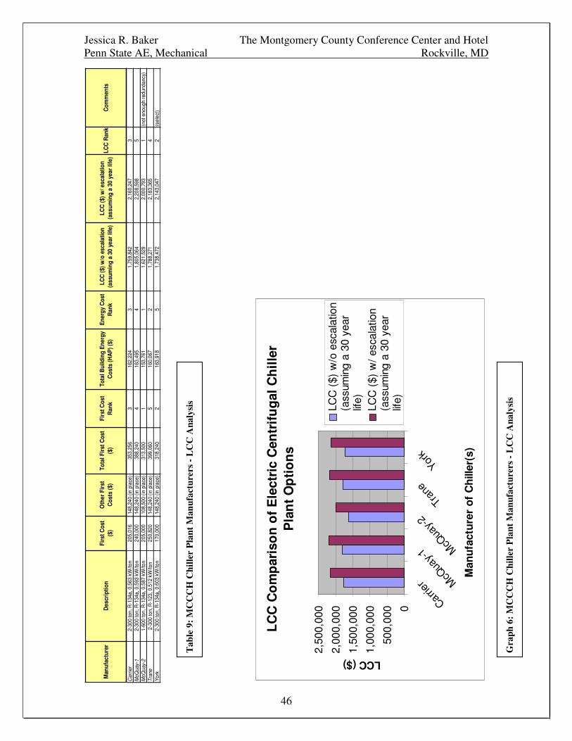
Tab
le9:
MC
CC
HC
hille
rP
lant
Man
ufac
ture
rs-
LC
CA
naly
sis
Gra
ph6:
MC
CC
HC
hille
rP
lant
Man
ufac
ture
rs-
LC
CA
naly
sis
Jessica R. Baker The Montgomery County Conference Center and HotelPenn State AE, Mechanical Rockville, MD
47
(The escalation factors mentioned throughout the above calculations refer to the
U.S. Department of Energy’s (DOE) predicted increase in electricity costs over
the next 30 years (U.S. Average Fuel Price Indices). See Appendix B calculations
for more information.)
Again, from the above calculations, tables, and graphs, it was very apparent that
the York central chilling plant with 2-300 ton centrifugal, vapor-compression
chillers coupled with 2 natural gas boilers was the most economical for the
Montgomery County Conference Center and Hotel. Its L.C.C. was much lower
than three of the other plant (manufacturer) options. One plant did have a lower
L.C.C. than the York plant but it consisted of McQuay’s 1-600 ton, double
compression machine. It was decided that this plant did not yield enough
redundancy and therefore, could not be selected as the optimum chiller plant for
the building.
So, the optimum design seemed to be the York manufactured central chilling
plant with 2-300 ton centrifugal, vapor-compression chillers coupled with 2
natural gas boilers. But, were there any ways to realize even more savings?
Cool Thermal Storage System Design
In order to examine the possibility of further operating cost savings, the addition
of cool thermal storage to MCCCH’s now electric central cooling plant was
studied. This method of ‘off-peak’ air-conditioning seemed like it might be very
beneficial to the building type and operating schedule.
ASHRAE’s Design Guide for Cool Thermal Storage was used as a tool to design
and evaluate a thermal energy storage system for MCCCH. The steps outlined in
this design guide are listed below:
- Calculating Load Profiles
- Screening Initial Economics
- Selecting Storage Type
- Selecting Operating Strategy
Jessica R. Baker The Montgomery County Conference Center and HotelPenn State AE, Mechanical Rockville, MD
48
- Determining Storage Interface Parameters
- Sizing the Cooling Plant and Storage
- Evaluating Economics
Everything on this list was covered in the cool thermal storage design for
MCCCH. However, some things may fall out of the specific sequence.
Step 1: Calculating Load Profiles
The building cooling load profile for MCCCH was produced by again using
Carrier’s Hourly Analysis Program. Schedules of the building’s occupancy,
equipment, lighting, and thermostats were estimated in order to produce
MCCCH’s overall building load profile as the building’s real operating schedules
were not known for this project.
The conference center was assumed to be at full occupancy from 8am to 6pm on
Monday-Thursday. On the weekends (Friday-Sunday), this half of the building
was assumed to be fully occupied from about 8:30am to 9:00pm.
During the week (Monday-Thursday), the hotel portion of MCCCH was expected
to be occupied at 100% from 5am to 6pm. For all other times, it was assumed to
be at 85%. On the weekends (Friday-Sunday), the hotel was expected to be
occupied at 100% at all times.
The building’s thermostat schedules throughout the building also followed these
hourly trends and the individual graphs of all of MCCCH’s operation schedules
can be viewed in Appendix D.
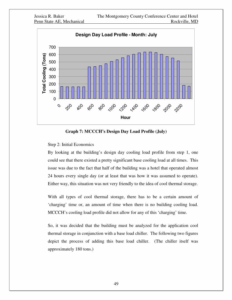
Finally, all of this data was input into HAP and the resulting design day cooling
load profile for July (the calculated design month for this geographic area) was
created.
Jessica R. Baker The Montgomery County Conference Center and HotelPenn State AE, Mechanical Rockville, MD
49
Design Day Load Profile - Month: July
0
100
200
300
400
500
600
700
020
040
060
080
010
0012
0014
0016
0018
0020
0022
00
Hour
To
talC
oo
ling
(To
ns)
Graph 7: MCCCH’s Design Day Load Profile (July)
Step 2: Initial Economics
By looking at the building’s design day cooling load profile from step 1, one
could see that there existed a pretty significant base cooling load at all times. This
issue was due to the fact that half of the building was a hotel that operated almost
24 hours every single day (or at least that was how it was assumed to operate).
Either way, this situation was not very friendly to the idea of cool thermal storage.
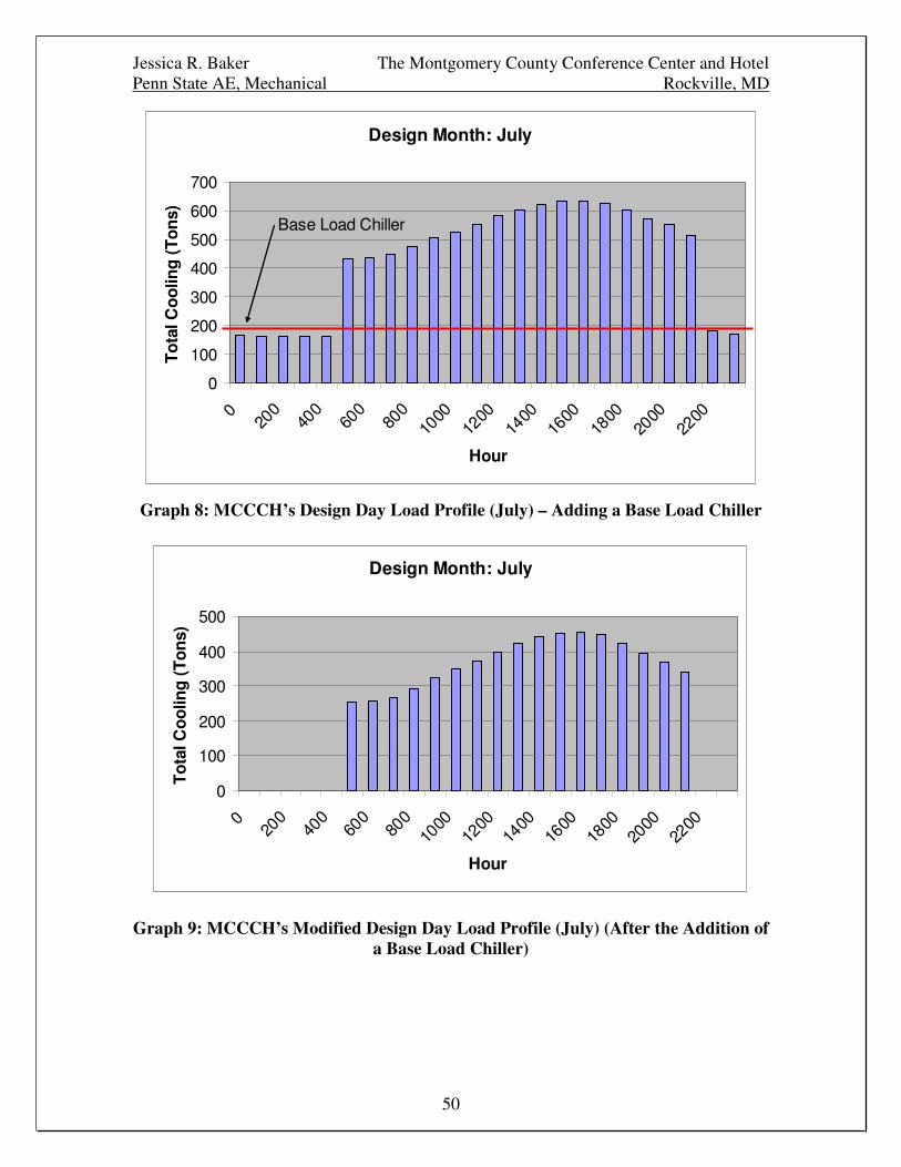
With all types of cool thermal storage, there has to be a certain amount of
‘charging’ time or, an amount of time when there is no building cooling load.
MCCCH’s cooling load profile did not allow for any of this ‘charging’ time.
So, it was decided that the building must be analyzed for the application cool
thermal storage in conjunction with a base load chiller. The following two figures
depict the process of adding this base load chiller. (The chiller itself was
approximately 180 tons.)
Jessica R. Baker The Montgomery County Conference Center and HotelPenn State AE, Mechanical Rockville, MD
50
Design Month: July
0
100
200
300
400
500
600
700
020
040
060
080
010
0012
0014
0016
0018
0020
0022
00
Hour
To
talC
oo
ling
(To
ns)
Base Load Chiller
Graph 8: MCCCH’s Design Day Load Profile (July) – Adding a Base Load Chiller
Design Month: July
0
100
200
300
400
500
020
040
060
080
010
0012
0014
0016
0018
0020
0022
00
Hour
To
talC
oo
ling
(To
ns)
Graph 9: MCCCH’s Modified Design Day Load Profile (July) (After the Addition ofa Base Load Chiller)

Jessica R. Baker The Montgomery County Conference Center and HotelPenn State AE, Mechanical Rockville, MD
51
Given this new cooling load profile, initial economic analyses of cool thermal
storage system designs could be conducted for MCCCH. The following storage
mediums and control strategies where evaluated as part of this initial study:
Daily, Full StorageDaily, Full Storage
Daily Partial Storage, Load LevelingDaily Partial Storage, Load Leveling
Daily Partial Storage, 50% Demand Limiting
(Ice Harvesting was not considered in this project due to the fact that the buildingwould never have 3 or more consecutive days per week of being unoccupied.)
By using the ASHRAE Design Guide for Cool Thermal Storage’s ‘rules of
thumb’, nominal chiller and storage capacities were calculated for each of the
storage mediums and operating strategies listed above. Electrical ‘on-peak’ and
‘off-peak’ times and charges were considered as well as MCCCH’s modified
cooling load profile. The resulting chiller and storage sizes are listed in the table
below. Full calculations can be viewed in Appendix D.
Summary of Ice Storage Calculations:
Operating Strategy Storage TypeChiller Size
(tons)Storage Size
(ton-h)
Non-Storage --- 420 ---Daily, Full Storage Chilled Water 894 6258Daily, Full Storage Glycol Ice 1277 6258
Daily Partial Storage, Load Leveling Chilled Water 261 1825Daily Partial Storage, Load Leveling Glycol Ice 286 1400
Daily Partial Storage, 50% Demand Limiting Glycol Ice 467 2288
**Ice Harveting not considered for several reasons.
Table 10: Ice Storage Calculation Results
From here, the design guide outlined a method for cost comparing the different
storage and operating types. General numbers and more ‘rules of thumb’ were
given in order to calculate the comparisons. Estimates and cost assumptions that
were used for this design project included:
- a chiller efficiency of 70%
- an ‘on-peak’ demand charge of $8/kW
- a chiller cost of $600/ton

Jessica R. Baker The Montgomery County Conference Center and HotelPenn State AE, Mechanical Rockville, MD
52
- a chilled water storage cost of $40/ton-hr
- a glycol ice storage cost of $60/ton-hr
- annual demand savings for full storage = 3 months of
peak savings and 5 months of 70% of peak savings
- annual demand savings for partial storage = 100% for
8 months
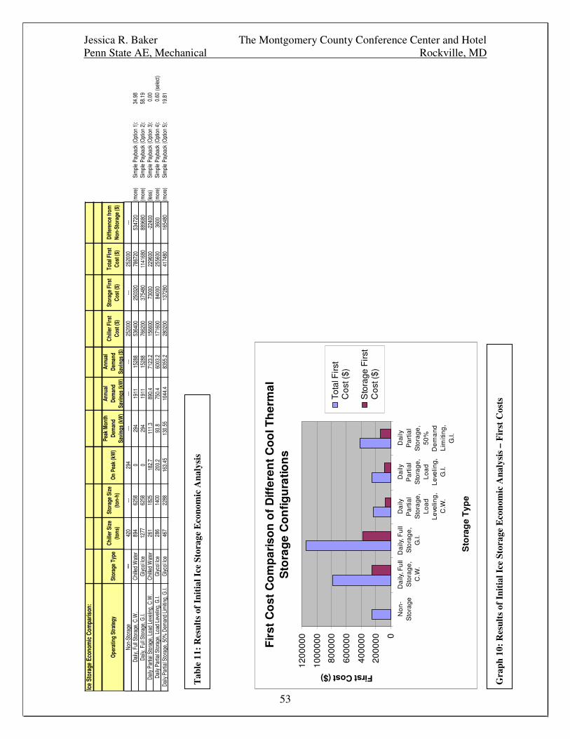
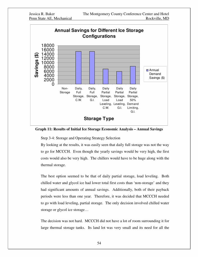
The results of all of these calculations can be seen in the table below. The graphs
following the table also depict the calculation results and serve as a visual
comparison of all the storage types/strategies.
Jessica R. Baker The Montgomery County Conference Center and HotelPenn State AE, Mechanical Rockville, MD
53
Ice
Stor
age
Econ
omic
Com
paris
on:
Ope
ratin
gSt
rate
gySt
orag
eTy
peCh
iller
Size
(tons
)St
orag
eSi
ze(to
n-h)
On
Peak
(kW
)Pe
akM
onth
Dem
and
Savi
ngs
(kW
)
Annu
alDe
man
dSa
ving
s(k
W)
Annu
alDe
man
dSa
ving
s($
)
Chill
erFi
rst
Cost
($)
Stor
age
Firs
tCo
st($
)To
talF
irst
Cost
($)
Diffe
renc
efro
mNo
n-St
orag
e($
)
Non-
Stor
age
---42
0---
294
------
---25
2000
---25
2000
---Da
ily,F
ullS
tora
ge,C
.W.
Chi
lled
Wat
er89
462
580
294
1911
1528
853
6400
2503
2078
6720
5347
20(m
ore)
Sim
ple
Payb
ack
(Opt
ion
1):
34.9
8Da
ily,F
ullS
tora
ge,G
.I.G
lycol
Ice
1277
6258
029
419
1115
288
7662
0037
5480
1141
680
8896
80(m
ore)
Sim
ple
Payb
ack
(Opt
ion
2):
58.1
9Da
ilyPa
rtial
Stor
age,
Load
Leve
ling,
C.W
.C
hille
dW
ater
261
1825
182.
711
1.3
890.
471
23.2
1566
0073
000
2296
00-2
2400
(less
)Si
mpl
ePa
ybac
k(O
ptio
n3)
:0.
00Da
ilyPa
rtial
Stor
age,
Load
Leve
ling,
G.I.
Glyc
olIc
e28
614
0020
0.2
93.8
750.
460
03.2
1716
0084
000
2556
0036
00(m
ore)
Sim
ple
Payb
ack
(Opt
ion
4):
0.60
(sel
ect)
Daily
Parti
alSt
orag
e,50
%D
eman
dLi
mitin
g,G
.I.G
lycol
Ice
467
2288
163.
4513
0.55
1044
.483
55.2
2802
0013
7280
4174
8016
5480
(mor
e)Si
mpl
ePa
ybac
k(O
ptio
n5)
:19
.81
Fir
stC
ost
Co
mp
aris
on
of
Diff
eren
tC
oo
lTh
erm
alS
tora
ge
Co
nfig
ura
tion
s
0
2000
00
4000
00
6000
00
8000
00
1000
000
1200
000
No
n-
Sto
rag
eD
aily
,Fu
llS
tora
ge
,C
.W.
Da
ily,F
ull
Sto
rag
e,
G.I.
Da
ilyP
art
ial
Sto
rag
e,
Lo
ad
Le
velin
g,
C.W
.
Da
ilyP
art
ial
Sto
rag
e,
Lo
ad
Le
velin
g,
G.I.
Da
ilyP
art
ial
Sto
rag
e,
50
%D
em
an
dL
imiti
ng
,G
.I.
Sto
rag
eT
ype
FirstCost($)
Tota
lFirs
tC
ost(
$)
Sto
rage
Fir
stC
ost(
$)
Tab
le11
:R
esul
tsof
Init
ialI
ceSt
orag
eE
cono
mic
Ana
lysi
s
Gra
ph10
:R
esul
tsof
Init
ialI
ceSt
orag
eE
cono
mic
Ana
lysi
s–
Fir
stC
osts
Jessica R. Baker The Montgomery County Conference Center and HotelPenn State AE, Mechanical Rockville, MD
54
Annual Savings for Different Ice StorageConfigurations
02000400060008000
1000012000140001600018000
Non-Storage
Daily,Full
Storage,C.W.
Daily,Full
Storage,G.I.
DailyPartial
Storage,Load
Leveling,C.W.
DailyPartial
Storage,Load
Leveling,G.I.
DailyPartial
Storage,50%
DemandLimiting,
G.I.
Storage Type
Sav
ing
s($
)
AnnualDemandSavings ($)
Graph 11: Results of Initial Ice Storage Economic Analysis – Annual Savings
Step 3-4: Storage and Operating Strategy Selection
By looking at the results, it was easily seen that daily full storage was not the way
to go for MCCCH. Even though the yearly savings would be very high, the first
costs would also be very high. The chillers would have to be huge along with the
thermal storage.
The best option seemed to be that of daily partial storage, load leveling. Both
chilled water and glycol ice had lower total first costs than ‘non-storage’ and they
had significant amounts of annual savings. Additionally, both of their payback
periods were less than one year. Therefore, it was decided that MCCCH needed
to go with load leveling, partial storage. The only decision involved chilled water
storage or glycol ice storage…
The decision was not hard. MCCCH did not have a lot of room surrounding it for
large thermal storage tanks. Its land lot was very small and its need for all the
Jessica R. Baker The Montgomery County Conference Center and HotelPenn State AE, Mechanical Rockville, MD
55
parking it could get was very great. Only one small area existed on the exterior of
the building where thermal storage tanks might be able to be placed. This
location was behind the building, between the conference center and hotel, and
beside the generator fuel tank.
Therefore, because of this great lack of space, the smallest type of thermal storage
tanks had to be selected. So, ultimately, this meant glycol ice storage (as chilled
water storage/stratified tanks are extremely large in size (sensible storage=no
phase change=larger tanks)). There was room at the building’s site for glycol ice
storage tanks.
Step 5: Storage Interface Parameters
Before a detailed design could take place, certain building distribution interface
parameters had to be determined and/or verified. The parameters that were of
greatest concern are listed below:
- The building was to have a 180 ton, base load, York,
electric chiller (screw chiller to be exact).
- The building’s chilled water supply temperature was 44F.
- Calmac ICEBANK ice storage tanks had the ability to
supply chilled water temperatures between 34F and 44F
(internal melt, ice-on-coil).
- It was decided that this project would be based on the
Calmac ICEBANK ice storage system.
- The total chilled water flow rate to the building would be
1440 gpm (like the original design).
- The flow rate through the ice storage system would be
determined by the Calmac ICEPICK program and the ice-
making/cooling, York, electric, centrifugal chiller
(whatever size that chiller might turn out to be).
- A heat exchanger would have to be used between the ice
storage loop and the building’s chilled water loop due to
the large size of building/high cooling load > 500 tons
Jessica R. Baker The Montgomery County Conference Center and HotelPenn State AE, Mechanical Rockville, MD
56
(A.D.G.C.T.S.); this heat exchanger would have a
reasonable approach and would have a lot to do with
selecting the discharge temperature of the ice storage.
- The system configuration would include the ice-
making/cooling chiller upstream of the ice storage tanks for
greater chiller efficiencies, the base load chiller would
operate on the building chilled water side, and the heat
exchanger would be staged with the base load chiller. (A
flow diagram of the final design can be found in Appendix
G.)
Step 6 and 7: Final Sizing and Economic Evaluations
Both hand calculations and Calmac’s ICEPICK program were used in order to
determine the final size of MCCCH’s ice storage system. All the calculations and
program outputs for this sizing process can be found in Appendix D. The final
design included:
- (4) Calmac IceBank Model 1500 Tanks
- (1) York MAXE 300 Ton Ice-Maker/Chiller
- (1) Mueller Plate and Frame HTX (w/ 254
Plates/Frame, 1 Frame)
- (1) Bell and Gossett 50 hp pump
- (1) York YCWS Screw Chiller 180 Tons (Base Load)
- (1) 540 gpm Cooling Tower
- (1) 900 gpm Cooling Tower
- (2) Bell and Gossett 15 hp pumps
- (1) Bell and Gossett 10 hp pump
- (1) Bell and Gossett 5 hp pump
A schematic of this design can be found in Appendices F and G along with all of
the equipment selection ‘cut sheets’. The schematic shows all the design flow
rates and the ‘cut sheets’ show all the design chiller efficiencies and/or kW/ton at
different operating capacities.
Jessica R. Baker The Montgomery County Conference Center and HotelPenn State AE, Mechanical Rockville, MD
57
The 4 Calmac model 1500 tanks were located outside of the building in the
location that was mentioned before in this report. Their exact location can be
seen on a drawing included in Appendix D. Additionally, the tanks were partially
buried as to not affect the aesthetics of the building’s exterior and/or the views
from hotel guestrooms. Appendix D also shows a figure of a buried Calmac ice
tank.
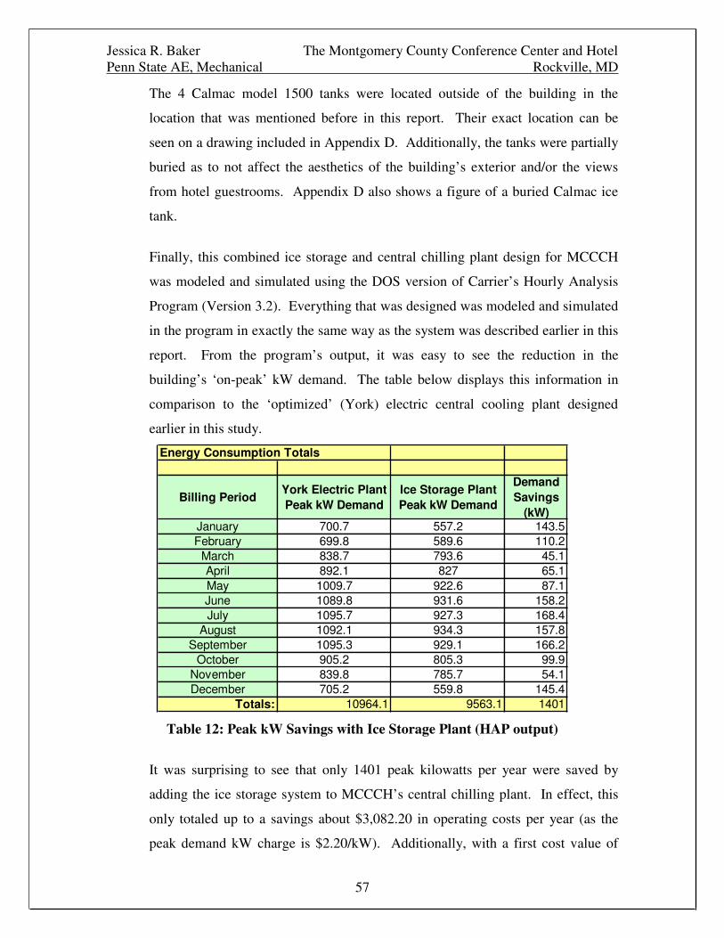
Finally, this combined ice storage and central chilling plant design for MCCCH
was modeled and simulated using the DOS version of Carrier’s Hourly Analysis
Program (Version 3.2). Everything that was designed was modeled and simulated
in the program in exactly the same way as the system was described earlier in this
report. From the program’s output, it was easy to see the reduction in the
building’s ‘on-peak’ kW demand. The table below displays this information in
comparison to the ‘optimized’ (York) electric central cooling plant designed
earlier in this study.
Energy Consumption Totals
Billing PeriodYork Electric PlantPeak kW Demand
Ice Storage PlantPeak kW Demand
DemandSavings
(kW)January 700.7 557.2 143.5February 699.8 589.6 110.2
March 838.7 793.6 45.1April 892.1 827 65.1May 1009.7 922.6 87.1June 1089.8 931.6 158.2July 1095.7 927.3 168.4
August 1092.1 934.3 157.8September 1095.3 929.1 166.2
October 905.2 805.3 99.9November 839.8 785.7 54.1December 705.2 559.8 145.4
Totals: 10964.1 9563.1 1401
Table 12: Peak kW Savings with Ice Storage Plant (HAP output)
It was surprising to see that only 1401 peak kilowatts per year were saved by
adding the ice storage system to MCCCH’s central chilling plant. In effect, this
only totaled up to a savings about $3,082.20 in operating costs per year (as the
peak demand kW charge is $2.20/kW). Additionally, with a first cost value of
Jessica R. Baker The Montgomery County Conference Center and HotelPenn State AE, Mechanical Rockville, MD
58
$425,922, the economics yielded a life-cycle cost of $2,249,006 (compare that to
the original York electric plant with a L.C.C. of $2,143,047!) and a payback
period of over 28 years. (These full economic calculations can be seen in
Appendix D.)
So, in concluding this section of the report, it was very clear that the addition of
this thermal ice storage design to MCCCH’s central cooling plant was not
economical and should not be done. Even though the tonnage of the central
cooling plant was reduced by 20% and the annual amount of peak demand
kilowatts was reduced, it wasn’t enough to justify the initial added system first
costs. There just weren’t enough savings. (One reason for this could have been
that the peak electric demand charge was just too small.)


