rIIrC2I BWR Vessel and Internals Project Jet Pump Repair Design Criteria (BWRVIP-51NP) NON-PROPRIETARY INFORMATION NOTICE: This report contains the non-proprietary information that is included in the proprietary version of this report. The proprietary version of this report contains proprietary information that is the intellectual property of BWRVIP utility members and EPRI. Accordingly, the proprietary report is available only under license from EPRI and may not be reproduced or disclosed, wholly or in part, by any Licensee to any other person or organization. I
Transcript
rIIrC2I
BWR Vessel and Internals Project Jet Pump Repair Design Criteria
(BWRVIP-51NP)
NON-PROPRIETARY INFORMATION NOTICE: This report contains the non-proprietary information that is included in
the proprietary version of this report. The proprietary version of this
report contains proprietary information that is the intellectual property
of BWRVIP utility members and EPRI. Accordingly, the proprietary
report is available only under license from EPRI and may not be
reproduced or disclosed, wholly or in part, by any Licensee to any
other person or organization.
I
REPORT SUMMARY
The Boiling Water Reactor Vessel and Internals Project (BWRVIP), formed in June, 1994, is an association of utilities focused exclusively on BWR vessel and internals issues. This BWRVIP report documents criteria which can be used to design a repair for the jet pumps in a BWR.
Background In the event that significant degradation is observed in BWR jet pumps, repair to those commponents may be required. Utilities need criteria which can be used in the development of those repair designs.
Objectives To compile the appropriate design criteria for jet pump repairs into a document which can be used by utility personnel performing the design and which could be submitted to appropriate regulatory agencies for approval of the generic design process.
Approach The contractor assembled a draft document which discussed all elements which need to be considered in designing a jet pump repair. Items discussed include: design objectives; structural evaluation; system evaluation; materials, fabrication and installation considerations; and, required inspection and testing. The resulting draft was reviewed in depth by BWRVIP utility representatives as well as third party contractors. The final report incorporates comments received during those reviews.
Results The document provides general design acceptance criteria for the repair of jet pumps. Repairs designed to meet these criteria will maintain the structural integrity of the component under normal operation as well as under postulated transient and design basis accident conditions.
EPRI Perspective The criteria listed in the report define a standard set of considerations which are important in designing a jet pump repair. It is intended that these criteria will be submitted to the USNRC, and possibily non-US regulators, for their approval. Regulatory acceptance of these generic criteria will significantly reduce the utility effort required to obtain approval for plant-specific repairs.
PROJECT WOB501 EPRI Project Manager: Warren Bilanin Nuclear Power Group Contractor: Sargent and Lundy
For ordering information about this report, call the EPRI Program Manager at (650) 855-2340.
For membership information, call (650) 855-2514
TR-108718NP
Interest Categories Piping, reactor, vessel and internals Licensing and safety assessment
Key Words Boiling water reactor Repair Stress corrosion cracking Jet pump Vessel and internals
BWR Vessel and Internals Project
Jet Pump Repair Design Criteria (BWRVIP-51 NP)
TR-108718NP Research Project B501
Final Report, February 2000
Prepared by:
Sargent & Lundy LLC
BWRVIP Repair Committee
Prepared for
BOILING WATER REACTOR VESSEL & INTERNALS PROJECT and
EPRI
3412 HilMew Ave.
Palo Alto, California 94304
DISCLAIMER OF WARRANTIES AND LIMITATION OF LIABILITIES
This report was prepared by the organization(s) named below as an account of work sponsored or
cosponsored by the BWR Vessel and Internals Project (BWRVIP) and the Electric Power Research Institute, Inc. (EPRI). Neither BWRVIP, EPRI, any member of EPRI, any cosponsor, the
organization(s) named below, nor any person acting on behalf of any of them:
(a) makes any warranty or representation whatsoever, express or implied, (i) with respect to the use of
any information, apparatus, method, process or similar item disclosed in this report, including
mechantability and fitness for a particular purpose, or (ii) that such use does not infringe on or
interfere with privately owned rights, including any party's intellectual property, or (iii) that this
report is suitable to any particular user's circumstance, or
(b) assumes any responsibility for any damages or other liability whatsoever (including any
consequential damages, even if BWRVIP, EPRI or any EPRI representative has been advised of the
possibility of such damages) resulting from your selection or use of this report or any information,
apparatus, method, process or similar item disclosed in this report.
Organization(s) that prepared this report:
Sargent & Lundy LLC
BWRVIP Repair Committee
ORDERING INFORMATION
Requests for copies of this report should be directed to the BWRVIP Program Manager, 3412 Hillview Ave., Palo Alto, Ca.
94304, (650) 855-2340.
ACKNOWLEDGMENTS
The members of the BWRVIP Jet Pump Repair Team, listed below, are gratefully acknowledged for their efforts which led to the successful completion of this document.
Priit Okas Kim Bezzant Paul Phelan Bob Geier Bruce McLeod Ken Wolfe
Table 1 Plant Configurations Evaluated ..................................................................... 2 Table 2 Summary of Recommended ASME Design Guidance .................................... 14 Table 3 Load Combinations for Mark I Plants ............................................................. 21 Table 4 Load Combinations for Mark II & III Plants ..................................................... 22 Table 5 Load Term Definitions for Tables 3 and 4 ...................................................... 23
vii
viii
Executive Summary
The Boiling Water Reactor Vessel and Internals Project (BWRVIP) was formed in June 1994 as a utility-directed initiative to address BWR vessel and internals issues. This criteria document was developed by the Repair Technical Subcommittee of the BWRVIP.
This document provides the general design acceptance criteria for permanent or temporary repair of jet pump assemblies. It is provided to assist BWR owners in designing repairs which maintain the structural integrity and system functionality of the jet pump assemblies during normal operation and under postulated transient and design basis accident conditions for the remaining plant life or other service life as specified by the plant owner.
Issuance of this document is not intended to imply that repair of jet pump assemblies is the only viable method for resolving cracking or excessive gaps in components. Due to variations in the material, fabrication, environment and as-found condition of individual components, and depending upon which component is degraded, repair is only one of several options that are available. The action to be taken for individual plants will be determined by the plant licensee.
ix
1.0 INTRODUCTION
1. 1 Background
Recently, the BWR Vessel and Internals Project (BWRVIP) prepared a safety assessment of BWR internals [ 1 ]. The evaluation of the jet pump assembly included consideration of the consequence of failure of several jet pump subassemblies. It was determined that inspection and evaluation procedures have a role in assuring the long term integrity of the jet pump safety functions. Subsequently, an inspection and flaw evaluation guideline [16]. for the jet pump assembly was prepared by the BWRVIP to provide a prioritized inspection strategy and guidance for evaluation of flaws.
In conjunction with inspection and flaw evaluation guidelines, a repair design criteria is outlined here for cases in which repair of jet pump components is warranted.
1.2 Purpose
The purpose of this document is to provide general design guidance and acceptance criteria for permanent and temporary repair ofjet pump assemblies. It is expected that individual licensees and vendors will adhere to these criteria in the application of plant-specific repairs.
The issuance of this document is not intended to imply that repair ofjet pump assemblies is the only viable approach to resolution of the cracking/degradation issue.
1.3 Scope
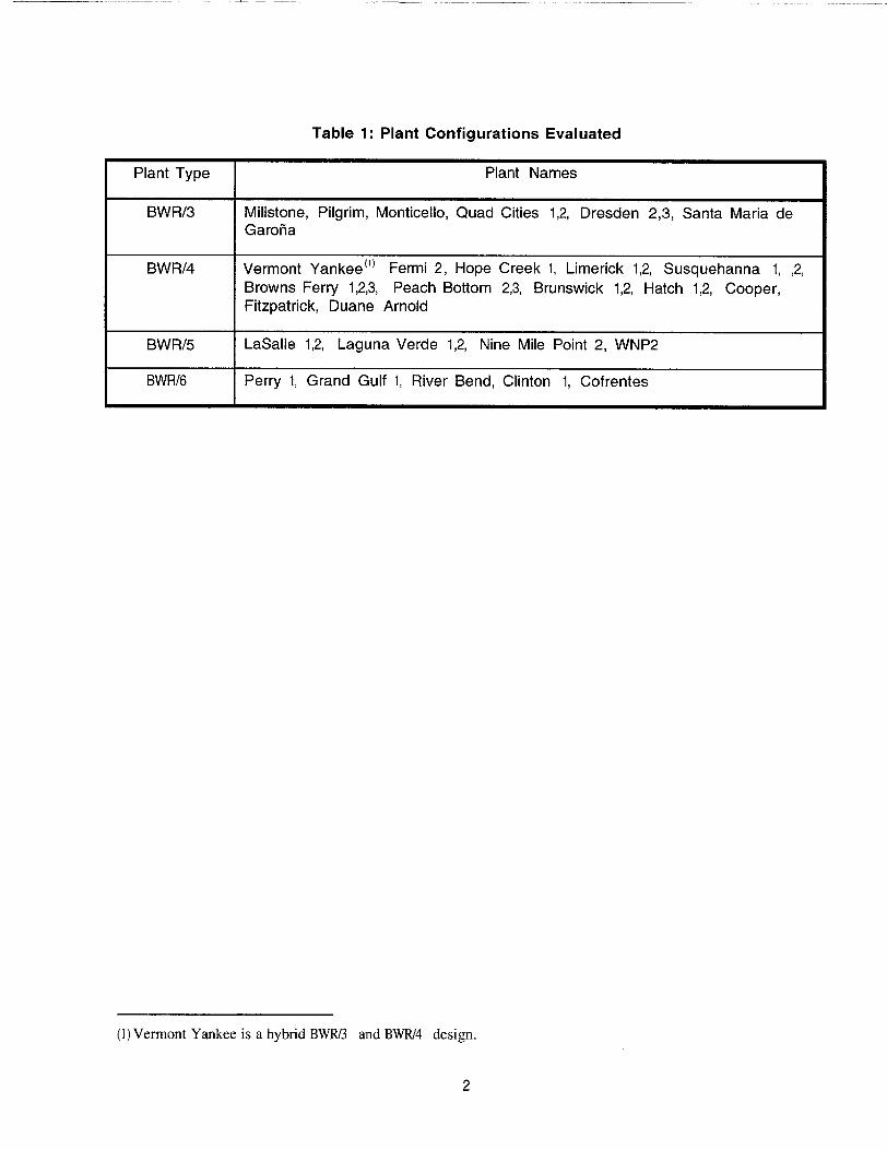
This document is applicable to General Electric BWR/3-6 plants (BWRD plants do not contain jet pumps). Table I shows the plant configurations that were specifically evaluated in preparing this Guideline. Configuration and material information included in the guideline is based on the best information available. Plants are advised to confirm the accuracy of this information when designing repairs. Plants not listed in Table 1 should obtain their configuration and material information elsewhere, but are not excluded from the scope of this Guideline.
I
Table 1: Plant Configurations Evaluated
(1) Vermont Yankee is a hybrid BWR/3 and BWR/4 design.
2
Plant Type Plant Names
BWR/3 Millstone, Pilgrim, Monticello, Quad Cities 1,2, Dresden 2,3, Santa Maria de Garofia
BWR/5 LaSalle 1,2, Laguna Verde 1,2, Nine Mile Point 2, WNP2
BWR/6 Perry 1, Grand Gulf 1, River Bend, Clinton 1, Cofrentes
2.0 DEFINITIONS
Replacement
Repair
Jet Pump Assembly
Safety Analysis Report
Replacement as used in the context of this document constitutes removal of components of the jet pump assembly that are subject to cracking and installation of new components in their place. The material and design shall be resistant to the cracking mechanisms that have been experienced in these components.
Repair as used in the context of this document is a broad term that applies to actions taken to design, analyze, fabricate and install hardware that restores the structural and functional integrity of the jet pump assembly. Repairs differ from replacement primarily in that the flaws are left in place. Weld overlay, without removal of the defect, as well as removal of flaws by a qualified machining process are also considered repairs in the context of this document.
The repairs may be temporary, i.e. designed for a specified amount of time, e.g. months of operation, or permanent, i.e. designed for the remaining life of the plant.
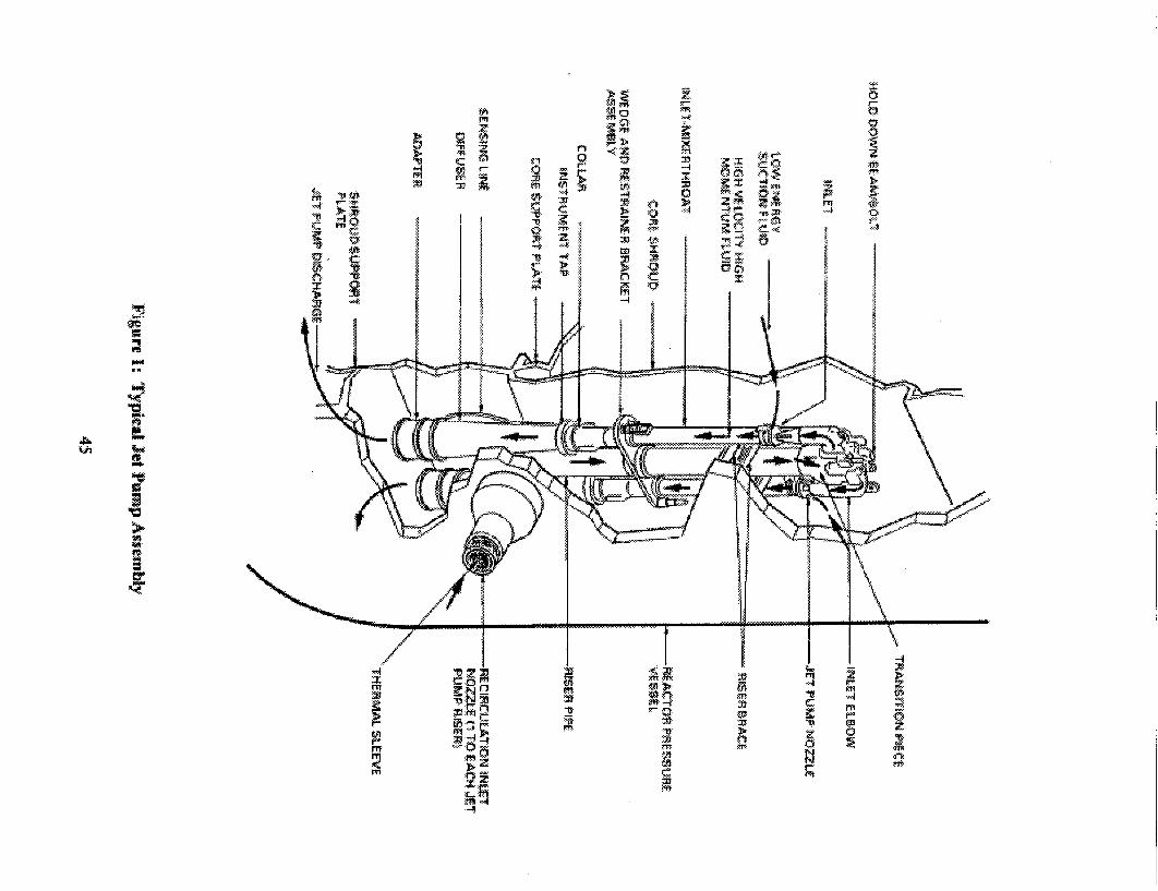
Figure I shows a typical jet pump assembly. Each jet pump assembly is composed of two jet pumps and a common riser assembly. The riser assembly is a pipe, internal to the RPV, which connects the recirculation pump discharge line to the jet pump pair. A riser brace attaches the riser pipe to the vessel wall to provide lateral support.
Safety Analysis Report (SAR) is used throughout this design criteria to refer to the current licensing document for the plant (e.g., FSAR, UFSAR, etc.).
3
3.0 JET PUMP ASSEMBLY CONFIGURATION AND SAFETY FUNCTION
3.1 Generic Physical Description
The jet pumps are located in the annulus region between the core shroud and the vessel wall and provide core flow to control reactor power. Between 6 and 12 pairs of jet pumps are found in the BWR/3 through BWR/6 plants; depending on plant rating. BWR/2 plants do not contain jet pumps. During normal operation, each
pair of jet pumps is driven by flow from a common riser pipe. The jet pump drive flow is pumped through the recirculation system through the riser and into each jet pump. Additional fluid from the annulus regino is entrained into the jet pump flow which is then directed to the lower plenum region.
Figure 1 shows a typical jet pump assembly. Figures 2 to 12 show typical component details. Each jet pump assembly is composed of two jet pumps and a common riser assembly. The riser assembly is a pipe, internal to the RPV, which connects the recirculation pump discharge line to the jet pump pair. A riser brace attaches the riser pipe to the vessel wall to provide lateral support.
Each jet pump consists of an inlet-mixer assembly and a diffuser assembly. The inlet-mixer assembly consists of a 180" elbow, a nozzle section with suction inlets, and a mixing section. The inlet-mixer assembly is clamped to the riser transition piece by the beam-bolt assembly, and fits into a slip joint at the top of the diffuser assembly. A restrainer bracket attached to the riser provides lateral support for each mixer section to increase the stiffness of the assembly and reduce the effects of vibration. The diffuser assembly consists of a conical section terminating in a straight cylindrical section at the lower end which is welded to the shroud support plate. Instrumentation monitors jet pump flow through the diffiser to ascertain individual and collective jet pump flow rates under operating conditions.
3.2 Safety Design Bases
Content Deleted EPRI Proprietary Information
5
3.3 Event Analyses
As previously stated, the purpose of this document is to provide general design criteria for repairs of degraded jet pump assembly components. Accordingly, various events and operational conditions must be considered to ensure that the repair does not inhibit the ability of the jet pump assembly to perform the basic safety and operational functions. The following general load cases shall be considered in design of the proposed repair.
4.1 This criteria applies to all of the jet pump assembly components except the flow sensing lines, the holddown beam and bolt assemblies, and the riser brace weld to the RPV. The holddown beam and bolt assemblies are readily replaceable and should be replaced rather than repaired if flaws are detected.
4.2 This criteria is not applicable to "like for like" replacement of components. Removal from the vessel to facilitate repairs of components would, however, be within the scope of this criteria.
4.3 The jet pump assembly repairs may address cracking in IGSCC susceptible components by a number of options. Local repairs such as weld overlays or mechanical devices which leave the flaws in place but structurally replace the flawed area may be used, or the flaw may be removed by a qualified machining process if it is not through-wall, with subsequent weld repair if required. Repairs include the hardware necessary to connect the new components to the existing assembly.
4.4 When either the vessel nozzle safe end or a weld attaching the nozzle thermal sleeve to the nozzle safe end is involved in the repair (the riser brace weld to the RPV is not in the scope of this criteria), ASME Class I requirements shall be invoked for the repair design within the ASME Section 11M and reactor pressure vessel jurisdiction.
4.5 Use of part circumferential weld overlays for repair of circumferential components shall follow the guidelines of Reference 17, previously developed for repair of RF'V internal core spray piping. This repair procedure may be applied to any circumferential weld in the jet pump assembly except welds to the RFW or nozzle safe end. The weld overlays may be made to the ID or OD of the component in wet or dry conditions provided the guidelines of Reference 17 are followed.
4.6 Repairs to reduce gaps at the interface of the restrainer bracket and inlet mixer such as auxiliary restrainer bracket wedges are within the scope of this repair criteria. See Section 7.12 for further guidelines.
4.7 For repairs where the structural integrity of a flawed section is restored to its original level, the supporting structural evaluation can be limited to a comparison between the original and repaired structural parameters such as cross-sectional area, moment of inertia and section modulus, provided the root cause of the degradation is not the result of inadequacy in the original structural design. For this type of repair, e.g. a sleeve-type mechanical repair or a weld repair, a detailed evaluation of loads and stresses would not be required.
7
5.0 DESIGN OBJECTIVES
5.1 Desim Life
Content Deleted EPRI Proprietary Information
5.2 Safety Desim Bases
Content Deleted EPRI Proprietary Information
5.3 Safety Analysis Events
Content Deleted EPRI Proprietary Information
5.4 Structural Inteqrity
Content Deleted EPRI Proprietary Information
5.5 Retained Flaw(s)
Content Deleted EPRI Proprietary Information
9
Content Deleted EPRI Proprietary Information
5.6 Loose Parts Considerations
Content Deleted EPRI Proprietary Information
5.7 Physical Interfaces with Other Reactor Internals
Content Deleted EPRI Proprietary Information
5.8 Installation
Content Deleted EPRI Proprietary Information
10
Content Deleted EPRI Proprietary Information
5.9 Jet Pump Performance and Leakage
Content Deleted EPRI Proprietary Information
5.10 Design Verification
Content Deleted EPRI Proprietary Information
II
12
6.0 GENERAL DESIGN CRITERIA
Content Deleted EPRI Proprietary Information
13
Table 2: Summary of Recommended ASME Design Guidance
Content Deleted EPRI Proprietary Information
14
7.0 STRUCTURAL AND DESIGN EVALUATION
Content Deleted EPRI Proprietary Information
7.1 Load Definitions - Applied Loads
Content Deleted EPRI Proprietary Information
Applicability of Hydrodynamic Loads
Content Deleted EPRI Proprietary Information
Deadweight CDW)
Content Deleted EPRI Proprietary Information
Hydraulic Loads (F)
Content Deleted EPRI Proprietary Information
15
Differential Pressure ODP)
Content Deleted EPRI Proprietary Information
Seismic Inertia
Content Deleted EPRI Proprietary Information
Seismic Anchor Displacements
Content Deleted EPRI Proprietary Information
16
Content Deleted EPRI Proprietary Information
Safetv Relief Valve Openingq (SRV)
Content Deleted EPRI Proprietary Information
Main Vent Clearinci (MVC)
Content Deleted EPRI Proprietary Information
Annulus Pressurization (AP)
Content Deleted EPRI Proprietary Information
17
Content Deleted EPRI Proprietary Information
Pool Swell, Condensation Oscillation and Chuqging (PS, CO. CHG)
Content Deleted EPRI Proprietary Information
Flow Induced Vibration (FIV)
Content Deleted EPRI Proprietary Information
Thermal and Pressure Anchor Displacement
Content Deleted EPRI Proprietary Information
18
Content Deleted EPRI Proprietary Information
7.2 Service Level Conditions
Content Deleted EPRI Proprietary Information
Service Level A (Normal OperatinQ Conditions):
Content Deleted EPRI Proprietary Information
Service Level B (Upset Conditions):
Content Deleted EPRI Proprietary Information
Service Level C (Emercencv Conditions):
Content Deleted EPRI Proprietary Information
19
Service Level D (Faulted Conditions):
Content Deleted EPRI Proprietary Information
7.3 Load Combinations
Content Deleted EPRI Proprietary Information
7.3.1 Mark I Plants
Content Deleted
EPRI Proprietary Information
7.3.2 Mark II and III Plants
Content Deleted EPRI Proprietary Information
20
TABLE 3 LOAD COMBINATIONS FOR MARK I PLANTS
Content Deleted EPRI Proprietary Information
21
TABLE 4 LOAD COMBINATIONS FOR MARK II & III PLANTS
Content Deleted EPRI Proprietary Information
22
TABLE 5 LOAD TERM DEFINITIONS FOR TABLES 3 AND 4
Content Deleted EPRI Proprietary Information
23
7.4 Allowable Stresses
Content Deleted EPRI Proprietary Information
7.5 Consideration of Shroud Repair or Cracking
Content Deleted
EPRI Proprietary Information
7.6 Flow Induced Vibration
Content Deleted EPRI Proprietary Information
24
Content Deleted EPRI Proprietary Information
7.7 Impact on Existing Internal Components
Content Deleted EPRI Proprietary Information
7.8 Radiation Effects on Repair Design
Content Deleted EPRI Proprietary Information
7.9 Analysis Codes
Content Deleted EPRI Proprietary Information
7.10 Thermal Cycles
Content Deleted EPRI Proprietary Information
25
7.11 Corrosion Allowance
Content Deleted EPRI Proprietary Information
7.12 Restrainer Bracket Adiusting Screw Gap Evaluation
Content Deleted EPRI Proprietary Information
26
8.0 SYSTEM EVALUATION
8.1 Leakacie
Content Deleted EPRI Proprietary Information
8.1 .1 Leakage Impact and Acceptance Criteria - Normal Operation
Content Deleted EPRI Proprietary Information
8.1.2 Leakaae Impact and Acceptance Criteria- Accident Conditions
Figure 9B: BWR/3,4 Solid Ring Restrainer Bracket Design
Content Deleted EPRI Proprietary Information
Figure 9C: Solid Ring Restrainer Bracket Design Typical of Most BWR/4-6s
Content Deleted EPRI Proprietary Information
Figure 1OA: BWR/3 Wedge Assembly-Welded to Restrainer Bracket
67
Content Deleted EPRI Proprietary Information
Figure 1OB: BWR/3 Wedge Assembly-Welded to Mixer
68
Content Deleted -
Content Deleted EPRI Proprietary Information
Figure 1OC: Typical BWR/4-6 Wedge Assembly
69
Content Deleted EPRI Proprietary Information
Figure 11A: Diffuser Assembly Typical of BWR/3 Plants with External Sensing Line Manifolds
Content Deleted EPRI Proprietary Information
Figure llB: Diffuser Assembly Typical of BWR/3 Plants wirth Partial Internal Sensing Line Manifolds
Content Deleted EPRI Proprietary Information
Figure llC: Typical BWR/4 Diffuser Assembly
--j tj
Content Deleted EPRI Proprietary Information
Figure liD: Typical BWR/5 Diffuser Assembly
Content Deleted EPRI Proprietary Information
Figure llE: Typical BWR/6 Diffuser Assembly
Content Deleted -
Content Deleted EPRI Proprietary Information
Figure 12A: Straight Adapter Assembly
75
Content Deleted EPRI Proprietary Information
Figure 12B: Curved Adapter Assembly
76
Content Deleted EPRI Proprietary Information
Figure 12C: Straight Adapter Assembly with Overlap
77
Content Deleted EPRI Proprietary Information
Figure 12D: Lower Ring Connection to Shroud Support Plate Typical of Most BWR/5s and 6s
78
Target:
Nuclear Power
About EPRI
EPRI creates science and technology solutions for the global energy and energy services industry. U.S. electric utilities established the Electric Power Research Institute in 1973 as a nonprofit research consortium for the benefit of utility members, their customers, and society. Now known simply as EPRI, the company provides a wide range of innovative products and services to more than 1000 energyrelated organizations in 40 countries. EPRI's multidisciplinary team of scientists and engineers draws on a worldwide network of technical and business expertise to help solve today's toughest energy and environmental problems.