31
Using Reflective Crack Interlayer- John Cheever, SemMaterials Nicola Upright, Colorado Department of Transportation
Using Reflective Crack Interlayer- John Cheever, SemMaterials Nicola Upright, Colorado Department of Transportation
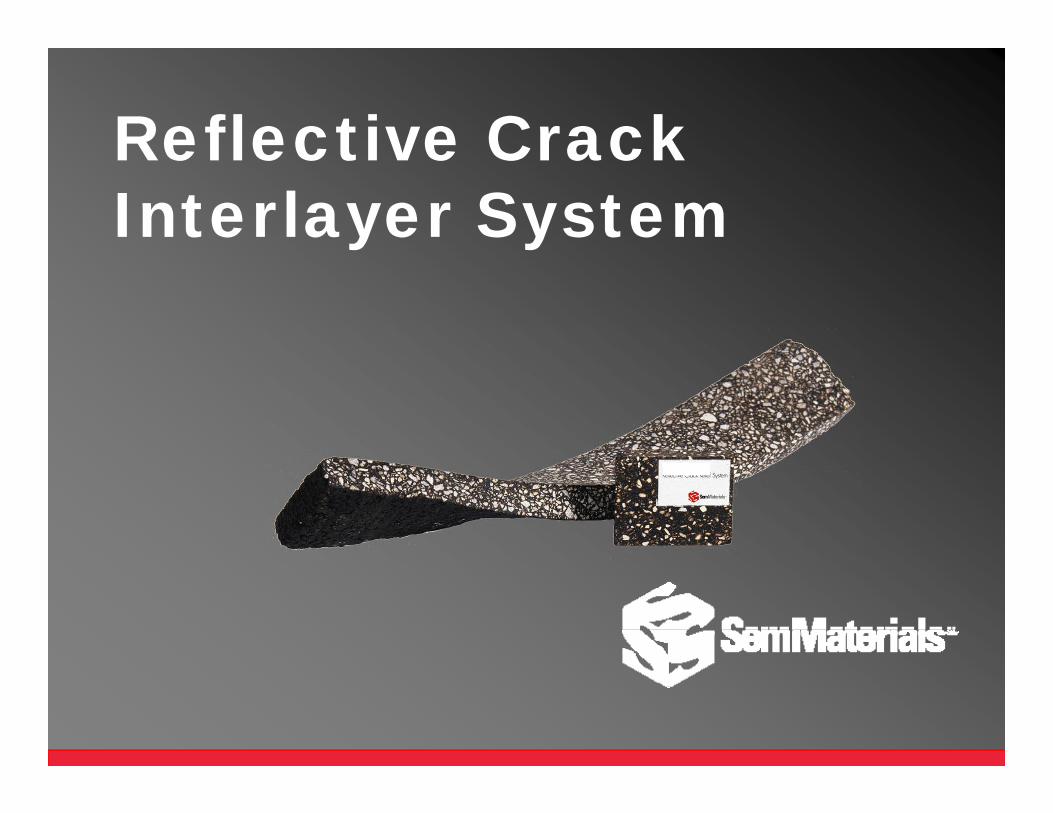
Reflective Crack Interlayer System
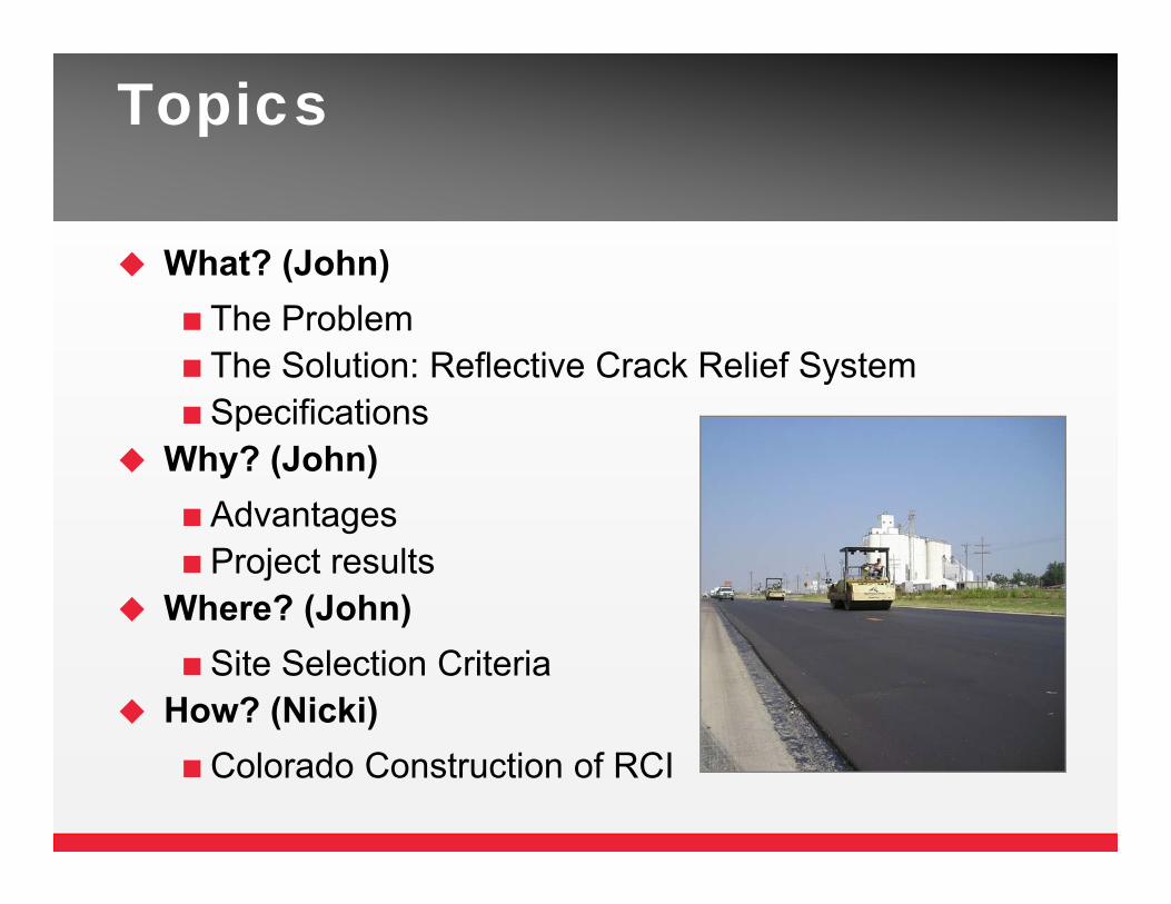
Topics
What? (John)The ProblemThe Solution: Reflective Crack Relief System Specifications
Why? (John)AdvantagesProject results
Where? (John)Site Selection Criteria
How? (Nicki)Colorado Construction of RCI
What?
The Problem
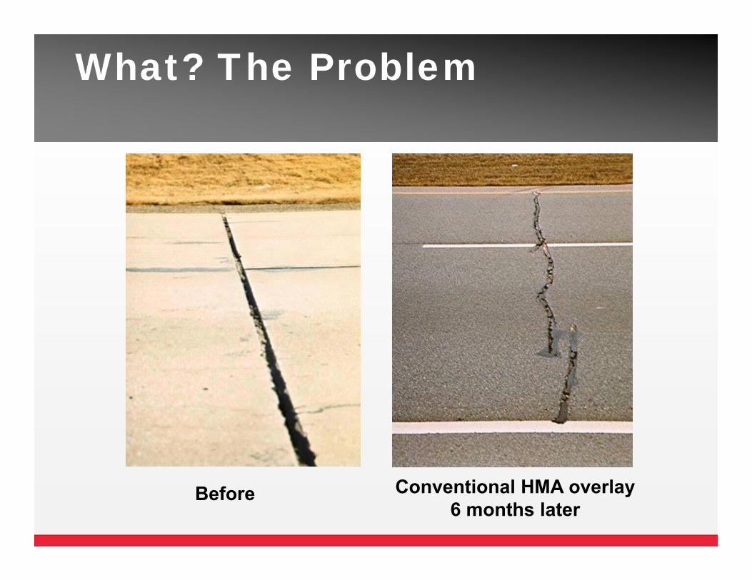
What? The Problem
Before Conventional HMA overlay6 months later
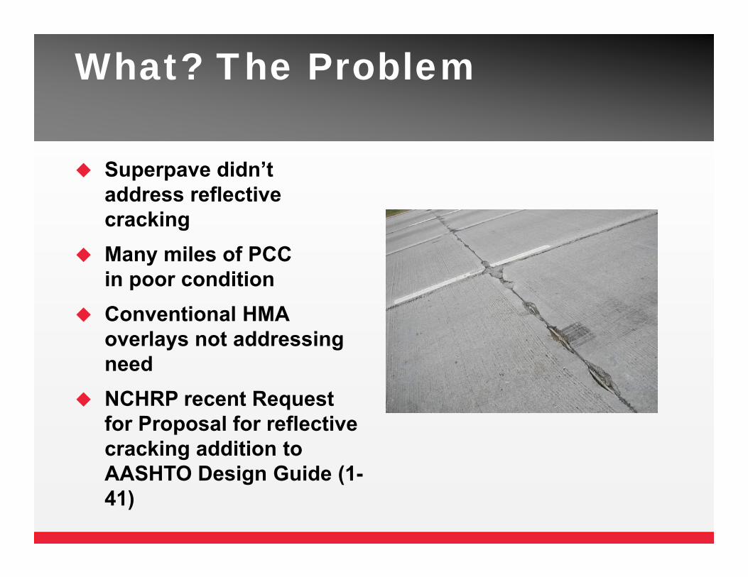
What? The Problem
Superpave didn’t address reflective cracking
Many miles of PCC in poor condition
Conventional HMA overlays not addressing need
NCHRP recent Requestfor Proposal for reflective cracking addition to AASHTO Design Guide (1-41)
What? The Solution
The SolutionReflective Crack Interlayer System
Significantly delays reflective cracking Protects pavement from moisture damage
(impermeable) Lengthens service life Recyclable
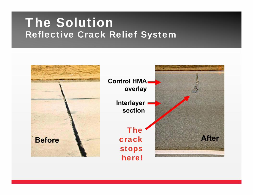
Before
The SolutionReflective Crack Relief System
After
Interlayer section
Control HMAoverlay
The crackstops here!
Overlay
InterlayerExisting PCC
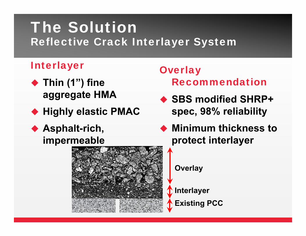
The SolutionReflective Crack Interlayer System
Interlayer Thin (1”) fine
aggregate HMA Highly elastic PMAC Asphalt-rich,
impermeable
Overlay Recommendation
SBS modified SHRP+ spec, 98% reliability
Minimum thickness to protect interlayer
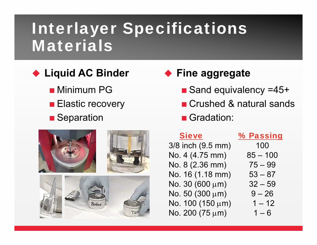
Interlayer Specifications Materials Liquid AC BinderMinimum PGElastic recoverySeparation
Fine aggregateSand equivalency =45+Crushed & natural sandsGradation:
Sieve % Passing3/8 inch (9.5 mm) 100No. 4 (4.75 mm) 85 – 100No. 8 (2.36 mm) 75 – 99No. 16 (1.18 mm) 53 – 87No. 30 (600 m) 32 – 59No. 50 (300 m) 9 – 26No. 100 (150 m) 1 – 12No. 200 (75 m) 1 – 6
Design Specifications Volumetrics
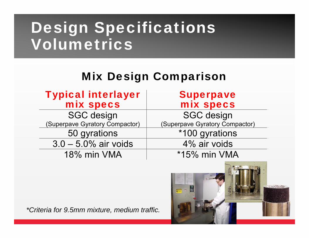
*Criteria for 9.5mm mixture, medium traffic.
Mix Design Comparison Typical interlayer
mix specs Superpave mix specs
SGC design (Superpave Gyratory Compactor)
SGC design (Superpave Gyratory Compactor)
50 gyrations *100 gyrations 3.0 – 5.0% air voids 4% air voids
18% min VMA *15% min VMA
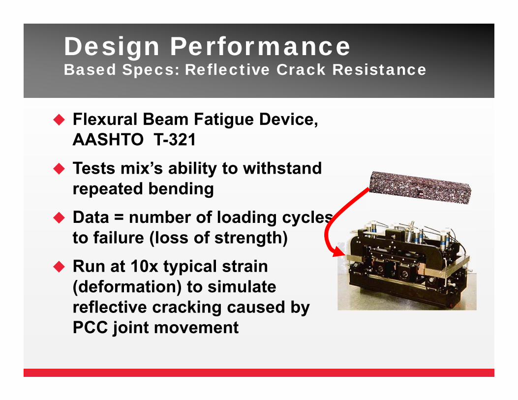
Design PerformanceBased Specs: Reflective Crack Resistance
Flexural Beam Fatigue Device, AASHTO T-321
Tests mix’s ability to withstand repeated bending
Data = number of loading cycles to failure (loss of strength)
Run at 10x typical strain (deformation) to simulate reflective cracking caused by PCC joint movement
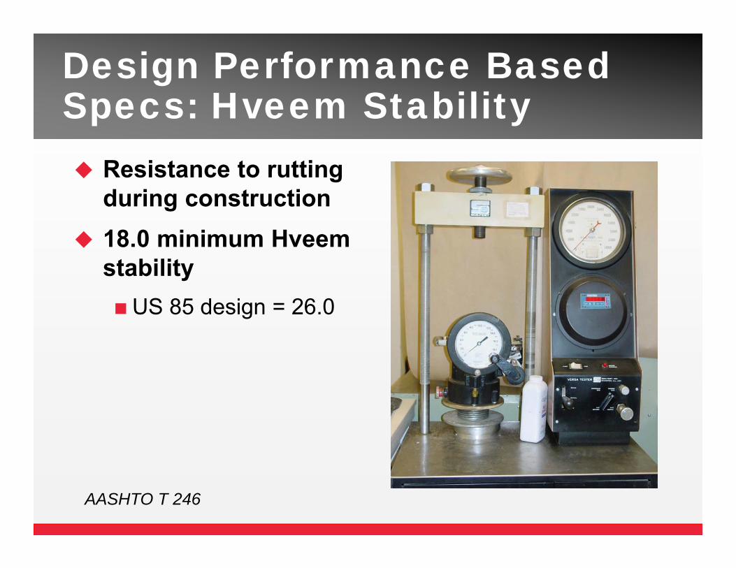
Design Performance Based Specs: Hveem Stability Resistance to rutting
during construction 18.0 minimum Hveem
stabilityUS 85 design = 26.0
AASHTO T 246
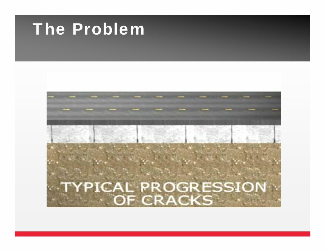
The Problem
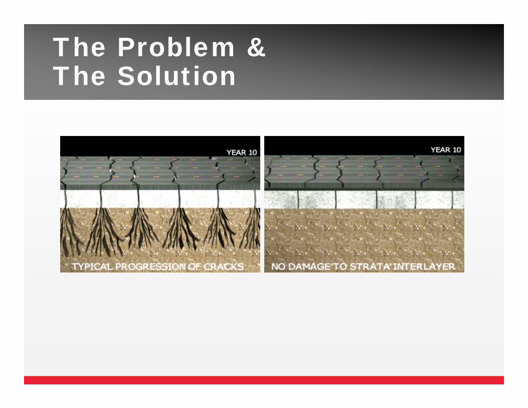
The Problem &The Solution
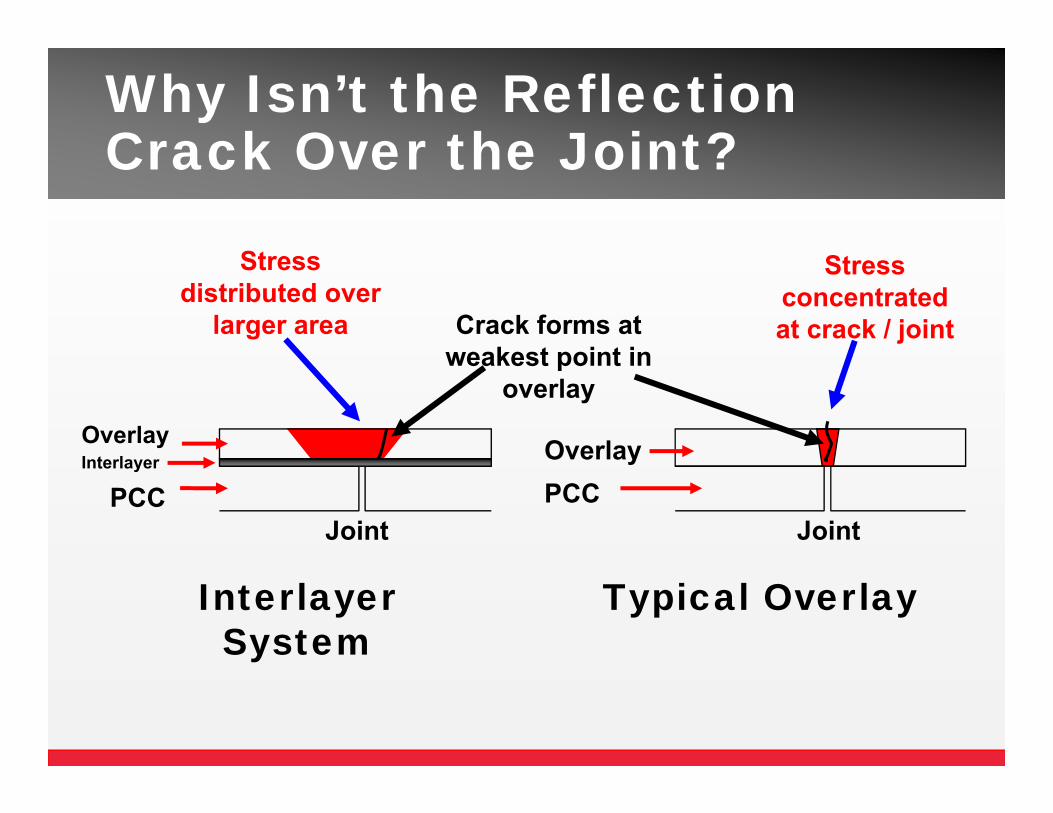
Why Isn’t the Reflection Crack Over the Joint?
Crack forms at weakest point in
overlay
Stress distributed over
larger area
Stress concentrated at crack / joint
Joint
Interlayer System
PCCJoint
Typical Overlay
OverlayPCC
OverlayInterlayer
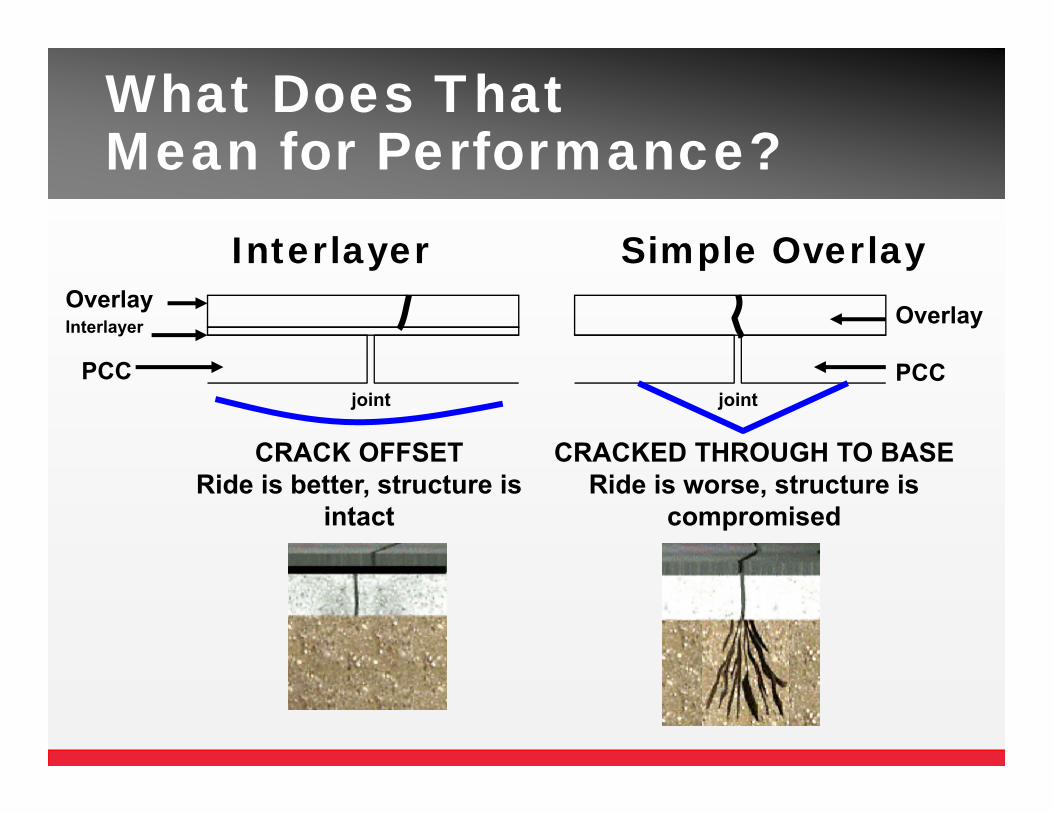
What Does That Mean for Performance?
OverlayInterlayer Overlay
PCC
Interlayer Simple Overlay
CRACKED THROUGH TO BASERide is worse, structure is
compromised
CRACK OFFSETRide is better, structure is
intact
jointjointPCC
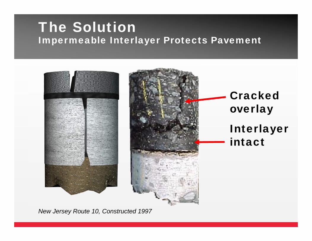
The Solution Impermeable Interlayer Protects Pavement
Cracked overlay
Interlayer intact
New Jersey Route 10, Constructed 1997
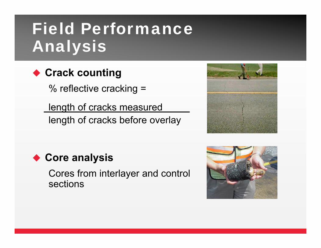
Field Performance Analysis Crack counting
% reflective cracking =
length of cracks measuredlength of cracks before overlay
Core analysisCores from interlayer and control sections
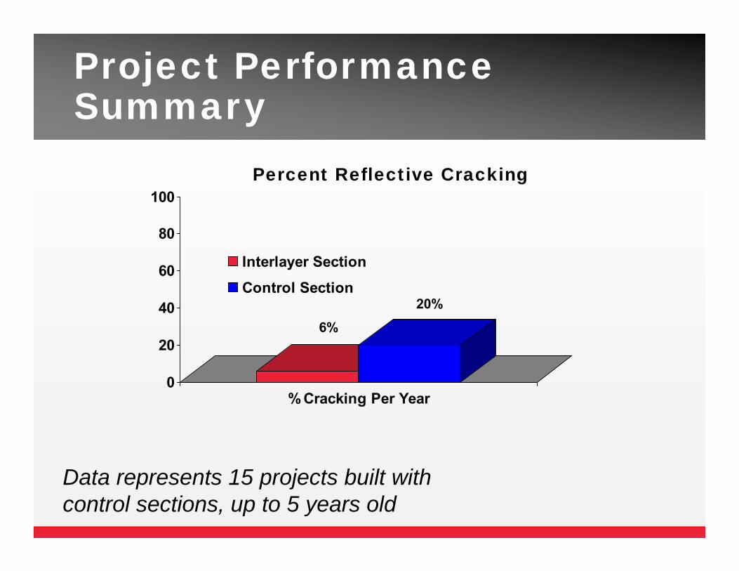
Project Performance Summary
Data represents 15 projects built with control sections, up to 5 years old
6%20%
0
20
40
60
80
100
% Cracking Per Year
Percent Reflective Cracking
Interlayer SectionControl Section
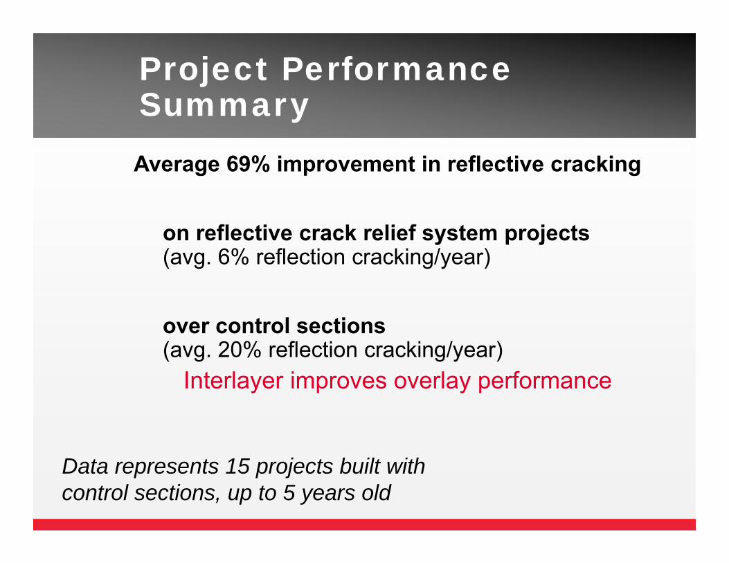
Project Performance SummaryAverage 69% improvement in reflective cracking
on reflective crack relief system projects(avg. 6% reflection cracking/year)
over control sections(avg. 20% reflection cracking/year)
Interlayer improves overlay performance
Data represents 15 projects built with control sections, up to 5 years old
Other Advantages
Can be recycled Mills easily
Standard HMA production & construction methodsUses locally available materials
Decreased construction timevs fabric, gridLower lane closures, user delay costs

Where?
Site Selection Guidelines
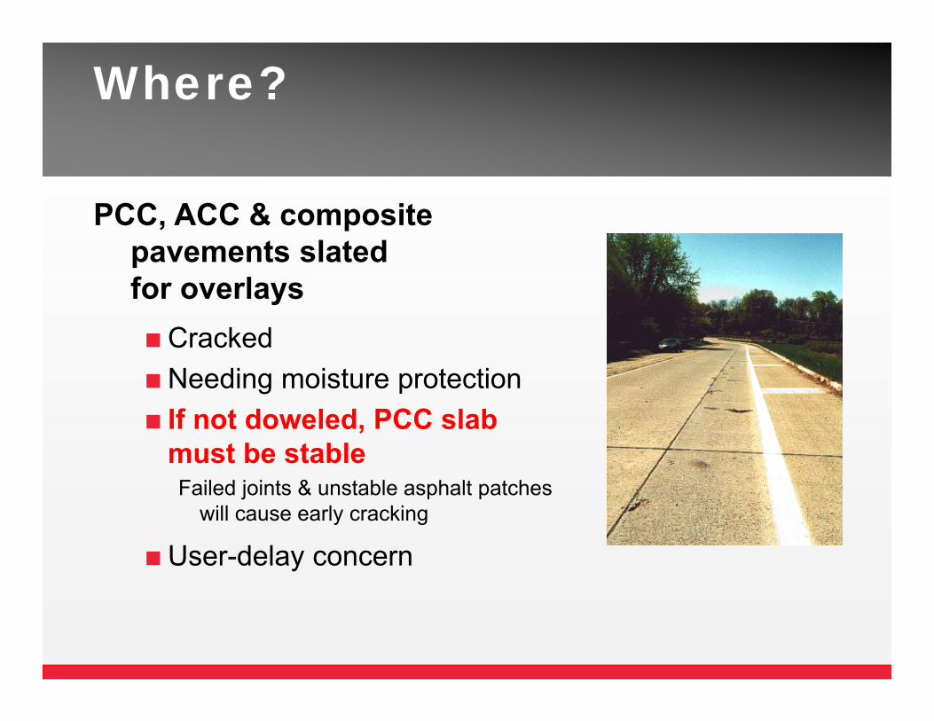
Where?
PCC, ACC & composite pavements slated for overlaysCracked Needing moisture protection If not doweled, PCC slab
must be stableFailed joints & unstable asphalt patches
will cause early cracking
User-delay concern
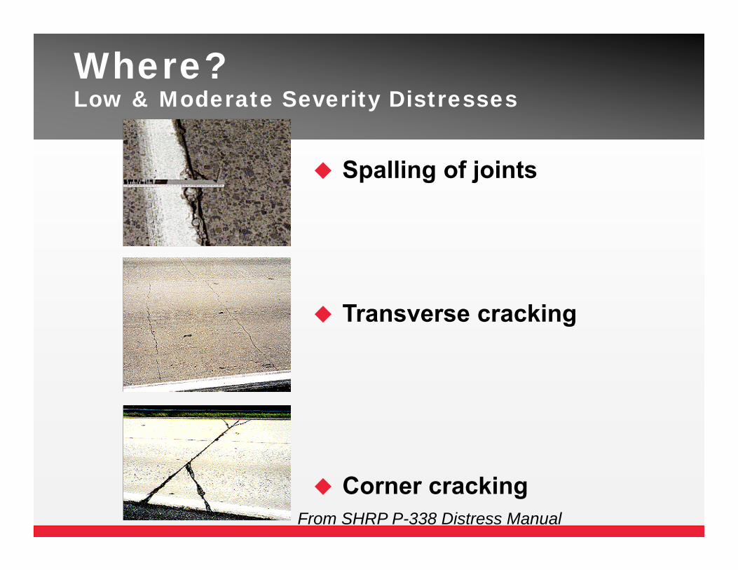
From SHRP P-338 Distress Manual
Where?Low & Moderate Severity Distresses
Spalling of joints
Transverse cracking
Corner cracking
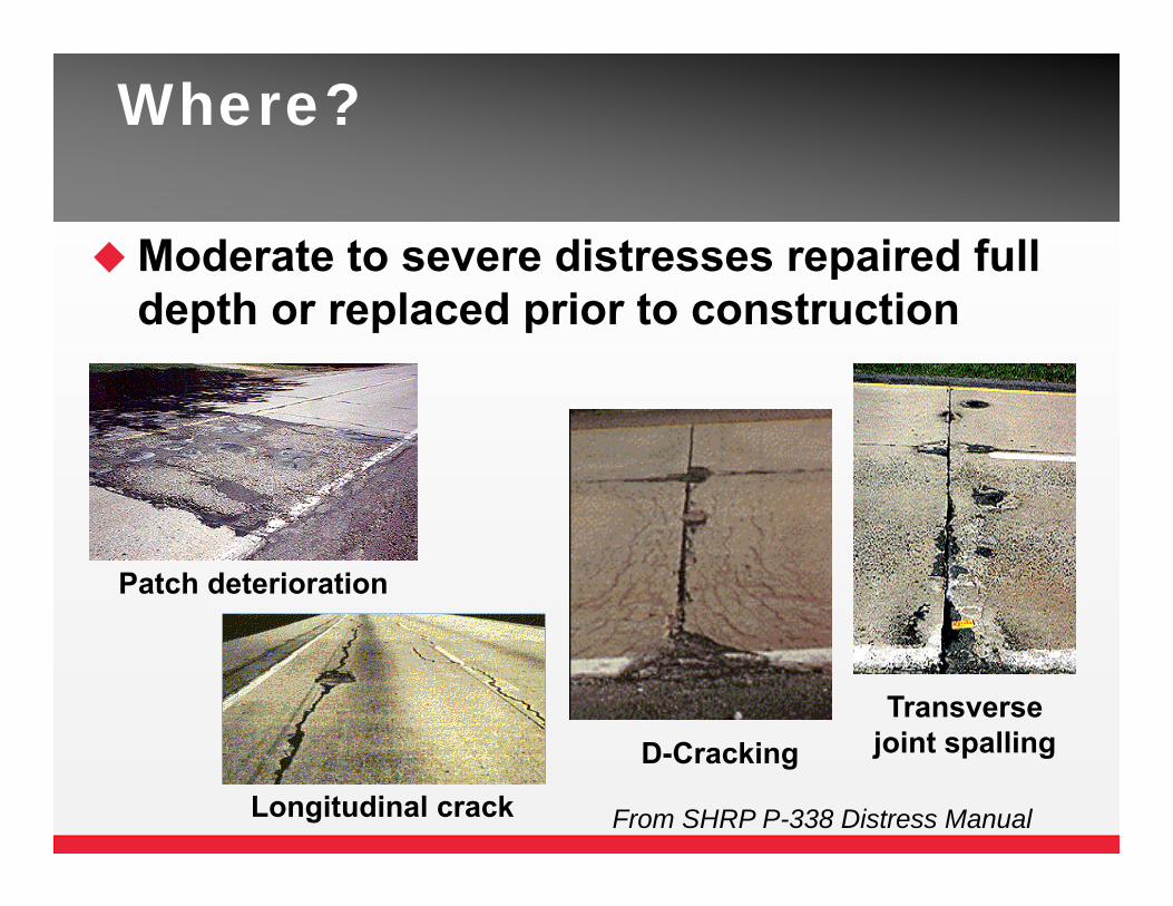
Where?
Moderate to severe distresses repaired full depth or replaced prior to construction
D-CrackingTransverse
joint spalling
From SHRP P-338 Distress Manual
Patch deterioration
Longitudinal crack
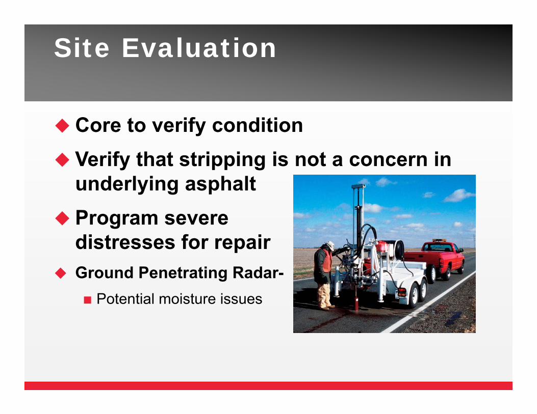
Site Evaluation
Core to verify condition Verify that stripping is not a concern in
underlying asphalt Program severe
distresses for repair Ground Penetrating Radar-
Potential moisture issues
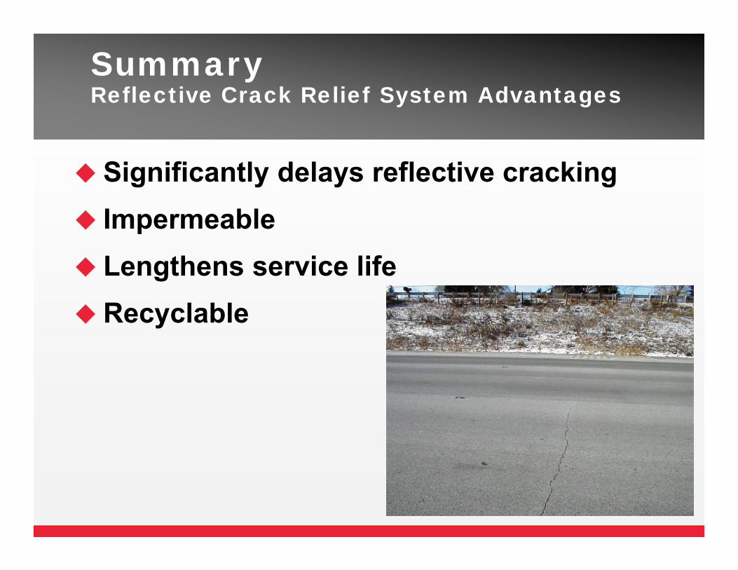
Summary Reflective Crack Relief System Advantages
Significantly delays reflective cracking Impermeable Lengthens service lifeRecyclable

Reflective Crack Relief System Projects- Colorado
Here’s Nicki!!!!

Thank you.
Questions?


