Acid mine drainage risks – A modeling approach to siting mine facilities in Northern Minnesota USA Tom Myers 1 6320 Walnut Creek Road, Reno, NV 89523, United States article info Article history: Received 24 June 2015 Received in revised form 4 November 2015 Accepted 11 December 2015 Available online 18 December 2015 This manuscript was handled by Geoff Syme, Editor-in-Chief, with the assistance of Craig T. Simmons, Associate Editor Keywords: Acid mine drainage Contaminant transport Groundwater modeling Watershed management summary Most watershed-scale planning for mine-caused contamination concerns remediation of past problems while future planning relies heavily on engineering controls. As an alternative, a watershed scale ground- water fate and transport model for the Rainy Headwaters, a northeastern Minnesota watershed, has been developed to examine the risks of leaks or spills to a pristine downstream watershed. The model shows that the risk depends on the location and whether the source of the leak is on the surface or from deeper underground facilities. Underground sources cause loads that last longer but arrive at rivers after a longer travel time and have lower concentrations due to dilution and attenuation. Surface contaminant sources could cause much more short-term damage to the resource. Because groundwater dominates baseflow, mine contaminant seepage would cause the most damage during low flow periods. Groundwater flow and transport modeling is a useful tool for decreasing the risk to downgradient sources by aiding in the placement of mine facilities. Although mines are located based on the minerals, advance planning and analysis could avoid siting mine facilities where failure or leaks would cause too much natural resource damage. Watershed scale transport modeling could help locate the facilities or decide in advance that the mine should not be constructed due to the risk to downstream resources. Ó 2015 Elsevier B.V. All rights reserved. 1. Introduction Acid mine drainage (AMD) is a problem associated with mines throughout the world (Jacobs and Testa, 2014). In the United States, promoting mining on public lands has been a priority since the 1800s (Leshy, 1987), with little consideration for the waste other than getting it away from the mine site being the practice prior to about 1970 (Church, 1996; Ferderer, 1996). Mines were developed with little concern regarding AMD (Crews, 1973; Williams, 1975). That is no longer the situation. Mining-caused contamination is a global problem and few sites are isolated or sufficiently under- used that potential contamination can be ignored. One example of global cooperation among the mining industry, conservation groups, and stakeholders to set a higher standard for mining, including the prevention of AMD and promotion of it remediation is the Initiative for Responsible Mining Assurance (IRMA) (http:// www.responsiblemining.net/). The goal of IRMA is to promote responsibility by certifying the most responsible mines. Watershed-scale planning is necessary to avoid the most seri- ous problems. However, much watershed-scale research focuses on remediation (Church et al., 2007; Crews, 1973; Kimball et al., 2006; Nimick and von Guerard, 1998; Skousen et al., 1999), often with the perspective of optimizing treatment (Crews, 1973; Kimball et al., 1999). Conceptual and numerical modeling at vari- ous scales can aid in prioritizing sites for remediation (Myers, 2013; Runkel et al., 2013). Herr et al. (2003) developed a watershed-scale model of AMD entering a river to show the con- taminant sources and potentially demonstrate the effectiveness of remediation of specific sites. Runkel and Kimball (2002) simu- lated flow and equilibrium chemistry along a stream heavily impacted by AMD to demonstrate the effects of remediation. Related modeling showed that simulation results are most affected by model parameters affecting a nearby stream reach or watershed (Gooseff et al., 2005). Myers (2013) suggested priorities for reme- diating phosphate mines based on a groundwater model of a large western watershed contaminated with selenium. Statistical mod- els also can show the mining features or geology that best explain the variability in salinity discharging from a mined watershed (Evans et al., 2014). These studies however do not suggest a means of avoiding AMD or other contamination issues as part of the plan- ning process. Preventing future mines from becoming AMD problems is often considered an engineering issue at the mine site (Jacobs et al., 2014; Buxton et al., 1997; EPA, 1994), although failures occur often http://dx.doi.org/10.1016/j.jhydrol.2015.12.020 0022-1694/Ó 2015 Elsevier B.V. All rights reserved. 1 Hydrologic Consultant. E-mail address: [email protected]Journal of Hydrology 533 (2016) 277–290 Contents lists available at ScienceDirect Journal of Hydrology journal homepage: www.elsevier.com/locate/jhydrol
6320 Walnut Creek Road, Reno, NV 89523, United States
a r t i c l e i n f o
Article history:Received 24 June 2015Received in revised form 4 November 2015Accepted 11 December 2015Available online 18 December 2015This manuscript was handled by GeoffSyme, Editor-in-Chief, with the assistance ofCraig T. Simmons, Associate Editor
Most watershed-scale planning for mine-caused contamination concerns remediation of past problemswhile future planning relies heavily on engineering controls. As an alternative, a watershed scale ground-water fate and transport model for the Rainy Headwaters, a northeastern Minnesota watershed, has beendeveloped to examine the risks of leaks or spills to a pristine downstream watershed. The model showsthat the risk depends on the location and whether the source of the leak is on the surface or from deeperunderground facilities. Underground sources cause loads that last longer but arrive at rivers after a longertravel time and have lower concentrations due to dilution and attenuation. Surface contaminant sourcescould cause much more short-term damage to the resource. Because groundwater dominates baseflow,mine contaminant seepage would cause the most damage during low flow periods. Groundwater flowand transport modeling is a useful tool for decreasing the risk to downgradient sources by aiding inthe placement of mine facilities. Although mines are located based on the minerals, advance planningand analysis could avoid siting mine facilities where failure or leaks would cause too much naturalresource damage. Watershed scale transport modeling could help locate the facilities or decide inadvance that the mine should not be constructed due to the risk to downstream resources.
� 2015 Elsevier B.V. All rights reserved.
1. Introduction
Acid mine drainage (AMD) is a problem associated with minesthroughout the world (Jacobs and Testa, 2014). In the UnitedStates, promoting mining on public lands has been a priority sincethe 1800s (Leshy, 1987), with little consideration for the wasteother than getting it away from the mine site being the practiceprior to about 1970 (Church, 1996; Ferderer, 1996). Mines weredeveloped with little concern regarding AMD (Crews, 1973;Williams, 1975).
That is no longer the situation. Mining-caused contamination isa global problem and few sites are isolated or sufficiently under-used that potential contamination can be ignored. One exampleof global cooperation among the mining industry, conservationgroups, and stakeholders to set a higher standard for mining,including the prevention of AMD and promotion of it remediationis the Initiative for Responsible Mining Assurance (IRMA) (http://www.responsiblemining.net/). The goal of IRMA is to promoteresponsibility by certifying the most responsible mines.
Watershed-scale planning is necessary to avoid the most seri-ous problems. However, much watershed-scale research focuses
on remediation (Church et al., 2007; Crews, 1973; Kimball et al.,2006; Nimick and von Guerard, 1998; Skousen et al., 1999), oftenwith the perspective of optimizing treatment (Crews, 1973;Kimball et al., 1999). Conceptual and numerical modeling at vari-ous scales can aid in prioritizing sites for remediation (Myers,2013; Runkel et al., 2013). Herr et al. (2003) developed awatershed-scale model of AMD entering a river to show the con-taminant sources and potentially demonstrate the effectivenessof remediation of specific sites. Runkel and Kimball (2002) simu-lated flow and equilibrium chemistry along a stream heavilyimpacted by AMD to demonstrate the effects of remediation.Related modeling showed that simulation results are most affectedby model parameters affecting a nearby stream reach or watershed(Gooseff et al., 2005). Myers (2013) suggested priorities for reme-diating phosphate mines based on a groundwater model of a largewestern watershed contaminated with selenium. Statistical mod-els also can show the mining features or geology that best explainthe variability in salinity discharging from a mined watershed(Evans et al., 2014). These studies however do not suggest a meansof avoiding AMD or other contamination issues as part of the plan-ning process.
Preventing future mines from becoming AMD problems is oftenconsidered an engineering issue at the mine site (Jacobs et al.,2014; Buxton et al., 1997; EPA, 1994), although failures occur often
278 T. Myers / Journal of Hydrology 533 (2016) 277–290
(Caldwell and Charlebois, 2010; Kuipers et al., 2006; Rico et al.,2008). The level of damage caused by these failures can dependon their location in the watershed. Missing from the literatureand generally from mine planning is research showing methodsdesigned to site mines and mine facilities to avoid large-scaleAMD problems when leaks occur.
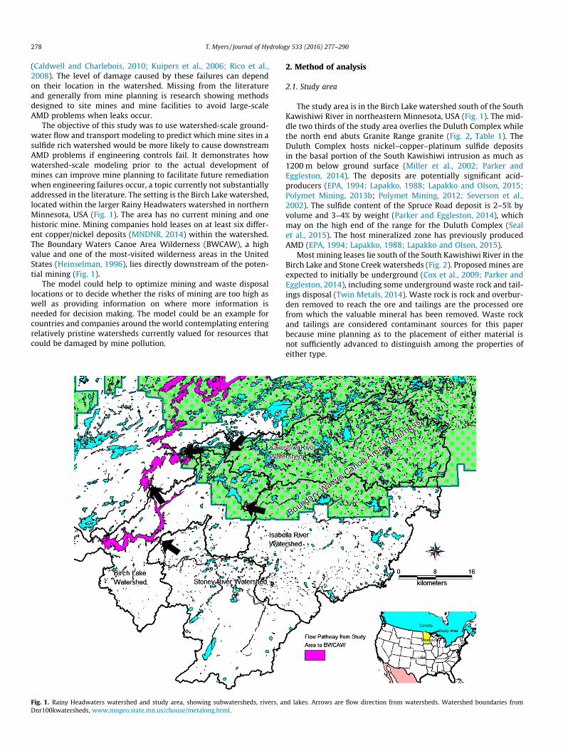
The objective of this study was to use watershed-scale ground-water flow and transport modeling to predict which mine sites in asulfide rich watershed would be more likely to cause downstreamAMD problems if engineering controls fail. It demonstrates howwatershed-scale modeling prior to the actual development ofmines can improve mine planning to facilitate future remediationwhen engineering failures occur, a topic currently not substantiallyaddressed in the literature. The setting is the Birch Lake watershed,located within the larger Rainy Headwaters watershed in northernMinnesota, USA (Fig. 1). The area has no current mining and onehistoric mine. Mining companies hold leases on at least six differ-ent copper/nickel deposits (MNDNR, 2014) within the watershed.The Boundary Waters Canoe Area Wilderness (BWCAW), a highvalue and one of the most-visited wilderness areas in the UnitedStates (Heinselman, 1996), lies directly downstream of the poten-tial mining (Fig. 1).
The model could help to optimize mining and waste disposallocations or to decide whether the risks of mining are too high aswell as providing information on where more information isneeded for decision making. The model could be an example forcountries and companies around the world contemplating enteringrelatively pristine watersheds currently valued for resources thatcould be damaged by mine pollution.
Fig. 1. Rainy Headwaters watershed and study area, showing subwatersheds, rivers, aDnr100kwatersheds, www.mngeo.state.mn.us/chouse/metalong.html.
2. Method of analysis
2.1. Study area
The study area is in the Birch Lake watershed south of the SouthKawishiwi River in northeastern Minnesota, USA (Fig. 1). The mid-dle two thirds of the study area overlies the Duluth Complex whilethe north end abuts Granite Range granite (Fig. 2, Table 1). TheDuluth Complex hosts nickel–copper–platinum sulfide depositsin the basal portion of the South Kawishiwi intrusion as much as1200 m below ground surface (Miller et al., 2002; Parker andEggleston, 2014). The deposits are potentially significant acid-producers (EPA, 1994; Lapakko, 1988; Lapakko and Olson, 2015;Polymet Mining, 2013b; Polymet Mining, 2012; Severson et al.,2002). The sulfide content of the Spruce Road deposit is 2–5% byvolume and 3–4% by weight (Parker and Eggleston, 2014), whichmay on the high end of the range for the Duluth Complex (Sealet al., 2015). The host mineralized zone has previously producedAMD (EPA, 1994; Lapakko, 1988; Lapakko and Olson, 2015).
Most mining leases lie south of the South Kawishiwi River in theBirch Lake and Stone Creek watersheds (Fig. 2). Proposed mines areexpected to initially be underground (Cox et al., 2009; Parker andEggleston, 2014), including some underground waste rock and tail-ings disposal (Twin Metals, 2014). Waste rock is rock and overbur-den removed to reach the ore and tailings are the processed orefrom which the valuable mineral has been removed. Waste rockand tailings are considered contaminant sources for this paperbecause mine planning as to the placement of either material isnot sufficiently advanced to distinguish among the properties ofeither type.
nd lakes. Arrows are flow direction from watersheds. Watershed boundaries from
Fig. 2. Bedrock geology and watersheds of the study area. See Table 1 for a description of the formations. See Fig. 1 for the watershed names. The black rectangles are miningleases and approximate location of the mineral deposits.
Table 1Geologic formations (Nicholson et al., 2007) along with model zone, layer and final calibrated horizontal and vertical conductivity (Kh and Kv, respectively) in meters/day. n iseffective porosity, Sy is specific yield, and Ss is storage coefficient.
T. Myers / Journal of Hydrology 533 (2016) 277–290 279
280 T. Myers / Journal of Hydrology 533 (2016) 277–290
2.2. Conceptual flow model
Four HU10-scale (USGS et al., 2013) watersheds form the studyarea: Birch Lake, Stony River, Isabella River, and Kawishiwi River(Fig. 1). Surface water flows north and west from Birch Lake andthe Kawishiwi River watershed through the Kawishiwi River andseveral lakes to the BWCAW. Rivers from the Stony River and Isa-bella River watersheds flow into the Birch Lake watershed (Figs. 1and 3). Lakes and wetlands connected by low-gradient rivers covermuch of the study area which generally has relief less than 10 mfrom a divide to nearby lakes and rivers.
A surficial aquifer consisting of glacial till or sand and gravelgenerally less than 3–6 m thick covers the area (Mast and Turk,1999). Hydraulic conductivity (K) of the sand/gravel surficial aqui-fer ranges from 0.000003 to 1070 m/d, or over nine orders of mag-nitude, for the surficial aquifer (Siegel and Ericson, 1981; Stark,1977; Winter, 1973). Well yields in the Kawishiwi watershed areless than 54 m3/d (Siegel and Ericson, 1981) reflecting the very thinto nonexistent surficial aquifers.
The Duluth Complex (Fig. 2) is a low-permeability intrusive for-mation with a very low K (Table 1) except possibly near some ofthe infrequent faulting, on which there is little available hydroge-ologic data (Miller et al., 2002; Thorleifson, 2008), and in the upper30 m which is relatively fractured with well yields from 27 to82 m3/d. The plutonic rocks have primary porosity up to 3%, butthe effective permeability is very low because the pores are iso-lated (Stark, 1977). The specific capacity of wells in the DuluthComplex ranges from 0.36 to 1.97 m3/d/m. In bedrock, fracturescontrol permeability and secondary porosity, and also flow paths.Porosity in the fractured Biwabik formation is as high as 50%.
Fig. 3. Location of wells with water levels, gage stations, perennial streams, and lakes inhtml#state_minerals_head.
Total flow, or total runoff, from the watershed above the gagefor US Geological Survey gaging stations in the area (Fig. 3), wasdivided into direct runoff and baseflow using methods of Limet al. (2005, 2010) (Table 2). Yield is total stream flow per areaand ranges from 21.6 to 31.2 cm per year (cm/y). Baseflow variesfrom 14.4 to 24.2 cm/y, although for watersheds with more than160 square km, it varies from 17.0 to 20.8 cm/y. Assuming rechargeis baseflow distributed over drainage area (Cherkauer, 2004;Scanlon et al., 2002), the average recharge is 19.2 cm/y, or0.00052 m/d for the study area.
Based on gages 7, 5, 2, and 1 (Table 2), subwatersheds BirchLake, Stony River, Isabella River, and Kawishiwi River (Fig. 3) yieldrecharge equal to 0.00052, 0.00047, 0.00049, and 0.00054 m/d,respectively. However, the low rates for the small watersheds,Dunka River near Babbitt and Filson Creek gages, 0.00044 and0.00046 m/d, respectively, illustrate the heterogeneity of therecharge distribution.
Many factors control the recharge distribution, including wet-lands, soil types, and soil landforms, including whether the soil iswell drained, whether the soils contain substantial peat (Siegelet al., 1995), and whether the bedrock is shallow. Using several sta-tewide GIS soils databases (Land Management Information Center,1996), maps of wetland coverage, hydrologic soil classification(NRCS, 2007), soil type, surface and subsurface permeability weredeveloped to illustrate the variability (Fig. 4a through e)(Cummins and Grigal, 1980).
A commonly-used method for estimating regional-scalerecharge in Minnesota for areas less than 5000 km2 based on pre-cipitation, growing degree days, specific yield (based on Rawlset al. (1982)) and baseflow recession indices (Delin et al., 2007;Lorenz and Delin, 2007) yielded a recharge estimate for the
the study area. See Table 2 for a list of gage stations. Source: http://mcc.mn.gov/gis.
Table 2U.S. Geological Survey gaging stations and station parameters. See Fig. 3 for the location. BFI is baseflow index, the proportion of total flow that is baseflow.
No USGS site no USGS site name Area (km2) Avg flow (m3/d) Avg runoff (m3/d) Base flow (m3/d) BFI Rech (m/d)
1 05124480 KAWISHIWI RIVER NEAR ELY, MN 657.9 461,164 108,226 352,938 0.77 0.000542 05124500 ISABELLA RIVER NEAR ISABELLA, MN 883.2 686,970 256,400 430,571 0.63 0.000493 05124990 FILSON CREEK IN SESW SEC. 24 NEAR WINTON, MN 25.0 18,642 7211 11,431 0.61 0.000464 05125000 SOUTH KAWISHIWI RIVER NEAR ELY, MN 0.05 991,271 248,969 742,301 0.75 0.000005 05125500 STONY RIVER NEAR ISABELLA, MN 466.2 307,811 89,744 218,067 0.71 0.000476 05126000 DUNKA RIVER NEAR BABBITT, MN 138.3 94,826 34,147 60,679 0.64 0.000447 05126210 SOUTH KAWISHIWI R ABV WHITE IRON LAKE NR ELY, MN 2167.8 1,573,205 443,911 1,129,295 0.72 0.000528 05126500 BEAR ISLAND RIVER NEAR ELY, MN 177.4 105,117 28,451 76,666 0.73 0.000439 05127000 KAWISHIWI RIVER NEAR WINTON, MN 3185.7 2,419,154 746,217 1,672,937 0.69 0.00053
10 05127205 BURNTSIDE RIVER NEAR ELY, MN 178.7 145,526 34,005 111,521 0.77 0.0006211 05127207 BJORKMAN’S CREEK NEAR ELY, MN 3.5 2626 1239 1388 0.53 0.0003912 05127210 ARMSTRONG CREEK NEAR ELY, MN 13.7 11,186 4516 6670 0.6 0.0004913 05127215 LONGSTORFF CREEK NEAR ELY, MN 22.9 18,984 7403 11,581 0.61 0.0005114 05127219 SHAGAWA RIVER Trib AT ELY, MN 1.8 259 155 103 0.4 0.0000615 05127220 BURGO CREEK NEAR ELY, MN 7.9 7977 3477 4499 0.56 0.0005716 05127230 SHAGAWA RIVER AT ELY, MN 256.4 219,331 49,307 170,025 0.78 0.0006617 05127500 BASSWOOD RIVER NEAR WINTON, MN 4506.6 3,284,031 724,319 2,559,712 0.78 0.00057
T. Myers / Journal of Hydrology 533 (2016) 277–290 281
Kawishiwi watershed of 20–30 cm/y. This estimate is similar to thetotal runoff yield and exceeds the recharge estimates made hereinby approximately 20–30%. Surface storage in wetlands and smalllakes and subsurface storage in the unsaturated zone and ground-water, which support long-term baseflow (Sophocleous, 2002),could explain the differences among estimates. Microscale topog-raphy embedded within larger flow systems connected by smallsurface drainages and interflow causes large variability in flowpathlength (Winter, 1998). This may cause surface runoff hydrographsto have long receding legs which resemble groundwater dischargeand are difficult to separate from the runoff hydrograph which maycause errors in estimates based on statistical analyses using base-flow recession (Delin et al., 2007; Lorenz and Delin, 2007).
Baseflow follows a seasonal pattern. Average monthly river flowat the Kawishiwi River near Ely gage peaks at more than 80 cm/yduring May just two months after the low flow of less than 8 cm/y recorded in March. Much recharge would occur during this snow-melt freshet flood because water runs on the ground surface andriver and stream levels are higher than the water levels in thestreambanks. After reducing to less than 20 cm/y by September,the baseflow fluctuates between 10 and 20 cm/y until reachingits low in March.
2.3. Conceptual transport model
Waste rock and tailings developed from ore bodies in the studyarea would likely become sources of AMD-related contaminantsbecause of accelerated oxidation of the ore’s high sulfide contents(Bain et al., 2000; EPA, 1994; Jacobs et al., 2014; Johnson andHallberg, 2005; Lapakko, 1988; Lefebvre et al., 2001; Nash andFey, 2007; Polymet Mining, 2013b, 2012). Oxidation within a sur-face waste rock dump, the most common means of disposal(Lottermoser, 2010; Nash and Fey, 2007), is complex due to multi-phase flow within the rock (Lefebvre et al., 2001). Pathways areeither across the ground surface (Nordstrom, 2011) or throughpoorly-buffered groundwater (Bain et al., 2000; Jones et al.,2014; Mayes et al., 2007; Siegel, 1981; Siegel and Ericson, 1981)to streams. Often, the existence of groundwater seepage containinga contaminant load is found only through tracers or synoptic sam-pling that finds a load at a certain location not accounted for bysurface samples (Kimball et al., 2002).
Waste may be backfilled underground to submerge the wastemore quickly and decrease the discharge of contaminants(Johnson and Hallberg, 2005). This means of disposal can be a sig-nificant short-term source of contaminants (Kohfahl et al., 2004;Neal et al., 2005; Runkel et al., 2013) as the recovering groundwater
submerges backfilledwaste and leaches oxidation products into thegroundwater.
Sulfate transport in the Rainy Headwaters is conservativebecause of a lack of buffering in the watershed and in general isconservative at typical concentrations (>100 mg/l) (Nordstrom,2011, 2008). Most transport through bedrock in this watershed isthrough fractures that have limited surface area limiting contacttime with any carbonate rock. Sulfate transport in groundwaterflow to streams has responded conservatively in other similar sit-uations (Neal et al., 2005; Nordstrom, 2008; Runkel et al., 2013). Agood example is Straight Creek in the Red River Valley of NewMexico; groundwater flowed through an unconfined debris-fanaquifer without attenuation of metals and with sulfate beingdiluted by fresher groundwater inflows (Nordstrom, 2008), asmodeled herein.
2.4. Numerical flow and transport model
A reconnaissance-level numerical flow and transport modelusing MODFLOW-2000 (Harbaugh et al., 2000) and MT3DMS(Zheng andWang, 1999) was developed to simulate the conceptualmodels described above. Model flowpaths and contaminant traveltimes were estimated using the MODPATH code (Pollock, 1994).The dominant model cell size is a 500-m square which approxi-mates the 16.2-hectare mining leases, expanding to 1000-msquares away from the leases in the upper Kawishiwi and IsabellaRiver watersheds (Fig. 5). Three model layers represent the generalstratigraphy, with layer 1 being the surficial till and sand/gravellayer and layers 2 and 3 being bedrock, with layer 2 bedrock beingmore fractured with higher K (Table 1). The top elevation wasbased on 30-m and 10-m digital elevation models (DEMs)(Fig. 5). Layer 1 was 15-m thick, based on the median and meandepth to bedrock being 14 and 17.4 m. Layer 2 thickness was setso that the total thickness of layers 1 and 2 equaled 140 m. Thebottom of layer 3 was set at elevation �1000 m.
MODFLOW DRAIN boundaries, head-controlled flux boundariesthat only allow water to leave the model domain, were specifiedfor larger lakes and rivers which cover most of the area due to closesurface–groundwater connections (Fig. 6). The lake boundary headwas set one m below the top elevation of the model cells so thatlakes would receive inflow only when the groundwater level isclose to the ground surface. The river head was set five m belowthe average top elevation of each model cell to simulate dischargeto rivers with embedded channels. General head boundaries (GHB),with head and distance to head based on lake water levels justacross the boundary, allow groundwater to cross the northern
Fig. 4. Distribution of wetlands and soil types across the study area (Cummins and Grigal, 1980). Stream file Strm_baseln3, lakes and wetlands from Dnr100khydrography,from www.mngeo.state.mn.us/chouse/metalong.html. Soil type: 1234; Factor 1: Texture of soil below 5 feet, S is sandy, L is loamy, C is clayey, X is mixed sand and loam, Y ismixed silt and clay, R is bedrock; Factor 2: Texture of soil in top 5 feet, as for factor 1; Factor 3: Drainage, W means well-drained, P means poorly drained; Factor 4: Color, D isdark, L is light.
282 T. Myers / Journal of Hydrology 533 (2016) 277–290
Kawishiwi watershed boundary (Fig. 6) at topographic low points.Recharge zones were specified based on subwatershed (Fig. 6),
with rates set so that recharge equals the measured baseflow inthe primary rivers.
Fig. 5. Model grid and layer 1 top elevation by cell in meters.
Fig. 6. Location of DRAIN and recharge boundaries in layer 1 and general head boundaries (GHBs) in layer 2. Final recharge rates equal 0.00054, 0.00049, 0.00047, and0.00052 m/d for zones 2 through 5, respectively.
T. Myers / Journal of Hydrology 533 (2016) 277–290 283
Transport modeling of sulfate was completed using MT3DMS(Zheng and Wang, 1999). In addition to advection controlled bythe flow model and effective porosity (Table 1), the variation ofwhich would simply proportionally increase or decrease contami-nant arrival time, dispersion affects concentration by spreading thecontaminants along and transverse to the flow path (Fetter, 1999).Dispersivity is a function of length of the flow path from source tosink (Fetter, 2002; Xu and Eckstein, 1995). The longest paths ema-nate from particle placement at mid-level in layer 3, and areapproximately 33,000 m, which is much longer than the length
at which further increases in dispersivity with length became neg-ligible, 1000 m (Xu and Eckstein, 1995). Because the flow paths inthis model domain vary from less than 100 m to as much as33,000 m, setting dispersivity for 1000 m is reasonable and avoidschanging D for each source. The apparent longitudinal dispersivitytherefore is 11.8 m. The transverse and vertical dispersivity equals0.2 and 0.1 times the longitudinal dispersivity (Schulze-Makuchet al., 1999). This analysis treats sulfate as conservative to estimatethe sources which could have the most significant impacts withoutrelying on estimates of reactivity to attenuate the risk.
284 T. Myers / Journal of Hydrology 533 (2016) 277–290
2.5. Flow model calibration
Steady state calibration is the process of adjusting K and bound-ary reach conductance so that simulated steady state groundwaterlevels match observed target groundwater levels and that simu-lated boundary fluxes equal measured fluxes (Anderson andWoessner, 1992). Within the four study area watersheds, thegroundwater level database (MN Geological Survey and MNDepartment of Health, http://www.mngeo.state.mn.us/chouse/metadata/wells.html) contained 1238 wells with 362 having depthto water, water level elevation, well depth, and depth to bedrock(Fig. 3). There are few groundwater level measurements in theheadwaters of the Isabella River and Kawishiwi River watershed,so nine artificial targets weighted 0.3 were set there in each modellayer with head set equal to ground surface elevation minus 4 m,similar to methods of Halford and Plume (2011).
Calibration was deemed sufficiently reliable for comparativetesting of the siting of contaminant sources (Nordstrom, 2012)when continued parameter estimation yielded composite scalesensitivity (CSS) within a few orders of magnitude for all parame-ters (Hill and Tiedeman, 2007), the parameter estimates ceasedchanging during automated calibration, and the sum of squaredresiduals (SSR) and actual mean residual was at a minimum.
2.6. Flow path simulation
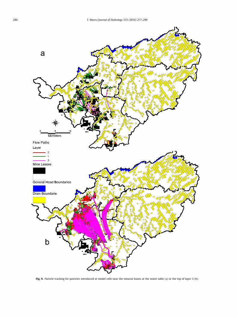
Advective pathways from the mineral leases (Fig. 2) to respec-tive discharge points, a DRAIN boundary, were determined andtimed using MODPATH (Pollock, 1994). Contaminant particleswere placed in approximately 630 model cells coincident withmineral leases (Fig. 2) at five different levels – the middle andtop of layer 3 and the middle and top of layer 2 to represent con-taminants leaching from underground, and the top of layer 1, orthe water table, to represent surface leaks through the vadosezone.
2.7. Transient model scenarios
The modeling scenarios are generic but representative of min-ing which could occur in this area (Parker and Eggleston, 2014;Polymet Mining, 2013a) with relatively stringent and well-enforced regulations. The simulated contaminant loads are similarto values expected for waste at the nearby proposed Polymet mine(Polymet Mining 2013a, 2013b, 2013c, 2012) because the ore is ofsimilar sulfide content and the hydrogeology is also similar. Thetwo model scenarios include one for which waste is backfilled intounderground workings and one for waste piled onto the groundsurface where leaching can occur. Model simulations were tran-sient, with a one-year period (20 time steps with 1.2 multiplier)of waste input, as described below, and a 1000-year period (60time steps, 1.1 multiplier) of long-term transport. The one-yearperiod of contaminant injection is conservative because if engi-neering plans go wrong or a leak goes undetected, the contaminantsource could continue for much longer. Groundwater fluxes con-tinue as simulated in steady state except for the small amount ofinjection used to simulate the underground waste. Simulationsdo not consider mine dewatering or other water managementactivities.
Waste in underground workings oxidizes, but the ratedecreases manyfold after the water level recovers and saturatesthe waste (Demchak et al., 2004; Kohfahl et al., 2004). As thewater level recovers, it flows through the waste leaching a con-taminant load into the surrounding groundwater. To simulate thisleaching as a sulfate load to groundwater, a low-flow (60 m3/d),high-concentration (10,000,000 lg/l, based on concentrationsexpected at the nearby proposed Polymet mine (Polymet
Mining, 2013a, 2013c)), injection well was placed within eachof five model cells in model layers 2 and 3 at five locations rep-resentative of the mineral leases (Fig. 2). The placement of a sul-fate source at different levels and locations allows considerationof the sensitivity of the flow paths emanating from the differentlocations of backfilled waste. The one-year period accounts forthe probable short-term cessation of oxidation as groundwaterlevels recover.
Above-ground sources, waste dumps, are simulated as a10,000,000 lg/l concentration added to the natural recharge oversix cells located as for the underground sources. This concentrationis an order of magnitude higher than observed in the field for sim-ilar ore (Lapakko and Olson, 2015), but justified because the sam-ples in that paper were taken downstream of the source after somedilution. The one-year simulation period is the equivalent of theoperator developing a waste rock storage area and covering it afterdiscovering a leak, completing reclamation over a one-year timeperiod, or moving the waste to a different location. Total load var-ies from 2,847,000 kg to 2,573,250 kg depending on cell size.
3. Results and discussion
3.1. Calibration
The final SSR was 4405 and 2173 for unweighted and weightedtargets, respectively. The standard deviation is 4.2% and 3.0% of the150-m range in observations, from the lowest to highest ground-water elevation. There is no detectable trend with observedgroundwater elevation and simulations should yield no bias. FinalKs for parameter zones (Fig. 7) are shown in Table 1.
Some of the wells cluster so closely (Fig. 3) they representessentially the same information, so they were thinned, first bykeeping just one well per layer within 200 m of each other, andsecond by keeping just one well per model cell with the head tar-get equal to average head of the wells remaining after the firstthinning (Wellman and Poeter, 2006).
Zones with few head observations were not sensitive so thefinal parameter values were selected on formation type and on val-ues necessary to generate reasonable head values (ASTM, 1998).Horizontal conductivity (Kh) values in the surficial aquifer are highbut within the observed values and vertical conductivity (Kv) val-ues reflect highly stratified till. Each bedrock formation K variesover at least two orders of magnitude. Conductivity decreases withdepth for most formations as expected due to compaction occur-ring due to overburden and less weathering with depth. In zones32 and 3, Kh was much less than Kv (Table 1) which reflects a ten-dency for vertical flow in the upthrust Duluth Complex (Milleret al., 2002).
Simulated heads generally show groundwater movement fromsoutheast to the north and northwest. The water table in the upperlayer follows the irregular topography while in the deep layer con-tours reflect a consistent slope to the northwest with an upwardgradient from layer 3 toward Birch Lake in the northwest portionof the study area near its primary surface water outlet (Figs. 3and 8).
Recharge (Fig. 6) and simulated discharge were nearly equiva-lent in the Isabella and Stony River watersheds but varied by from10% to 20% in the other watersheds due to interbasin groundwaterflow. Percent differences among watersheds are small and indicatethat the distribution of recharge and discharge through the modeldomain is accurate. All ten river reaches gain more flow in theirlower reaches near their outlet due to converging flow. Ten simu-lated lakes received zero discharge because their bottom wasabove the water table which reflects their location in the upperrecharge portions of the watersheds.
Fig. 7. Hydrogeology zones for three layers and steady state head target locations (black squares). Table 1 shows final conductivity values.
Fig. 8. Proportion of particles reaching surface water sources in a number of yearsfor any location in the specified layer.
T. Myers / Journal of Hydrology 533 (2016) 277–290 285
3.2. Particle tracking
Particles introduced at the middle level of layer 3, or about750 m bgs, required the longest and those introduced at the watertable required shortest time to reach surface water (Fig. 8), withminimum times varying from 26 years to less than a year, depend-ing on layer. About 2.8% and 23.5% of the particles released at thetop of layer 3 and middle of layer 2 reached surface water in lessthan 50 years, respectively (Figs. 8 and 9). Flow paths are longestthrough layer 3 because of the layer’s thickness. The shortest path-ways occur where a river boundary is close and there is an upwardgradient, such as near Birch Lake (Figs. 3 and 9).
The shortest pathways, requiring less than two years, were fromwater table sources starting close to rivers (Fig. 9). Most particlesreached surface water quickly, with 21% reaching surface waterwithin 10 years and 62.9% in 50 years (Fig. 8). Longer transporttimes were for particles being transported deeply into layer 2 or3 (Fig. 9).
The primary control on transport time, other than distance fromthe sink, is whether the particle sinks deeper into the bedrock(Gburek and Folmar, 1999), which would result from normalgroundwater circulation. Contaminants released where they sinkwould present a less substantial risk to downstream resources.However, long pathways could result in contamination remaininga risk long after mining has ceased if it does not attenuate.
Fig. 9. Particle tracking for particles introduced at model cells near the mineral leases at the water table (a) or the top of layer 3 (b).
286 T. Myers / Journal of Hydrology 533 (2016) 277–290
T. Myers / Journal of Hydrology 533 (2016) 277–290 287
3.3. Contaminant transport modeling
Detectable sulfate, at 1 lg/l, expanded through the groundwa-ter domain variously depending on the location of the source(Fig. 10). Sulfate from deep sources flows to the northwest withvarious amounts of lateral and vertical dispersion(Fig. 10a and b). Detectable sulfate reached up to 2.5 km from thesource with up to 1.5 km lateral dispersion (Fig. 10a). Near sources1 and 2 (source numbers specified in Fig. 10a), vertical dispersioncaused contours in the surface layer to almost mirror those inthe source layer. Sulfate originating at depth transports further ina thousand years than does sulfate originating on the surfacewhich is limited in extent by discharge to rivers (Fig. 10b).
Sulfate originating from surface sources disperses to the north-west from headwaters and radially from near-river sources(Fig. 10c). Sulfate from source 4 expanded to the northeast butwas constrained from expanding to the south by a steep topo-graphic slope (Fig. 10c). Between ten and a hundred years, the sul-fate contours did not spread significantly (Fig. 10c) due todischarge to surface waters while concentrations near the sourcedecreased by an order of magnitude.
The amount of groundwater affected depends on the source,flow paths and dispersion. Contaminants eventually reach surfacewater, but at widely varying travel times (Fig. 8). The load is mostimportant with respect to discharge to the rivers, and peak loadsreach the various river reaches at times depending on distance
Fig. 10. Concentration contours for (a) underground source after 10 years, (b) undergrouafter 100 years. Underground source is layer 3, surface source is layer 1. Alternate layernumber is shown in (a). Contours range from 1 to 100,000 lg/l from outer to inner.
and whether the source is surface or underground (Table 3). Peakloads from underground sources reached rivers in from ten to fortyyears and from surface sources in less than five years (Table 3 andFig. 8).
The highest sulfate loads from surface sources were up to twoorders of magnitude higher than those from underground sourcesand reach their peak at rivers in the Stony River watershed at theend of the first year, reflecting their close proximity of the sourceto the rivers. Filson Creek receives the highest load which trans-lates to a concentration of near 120,000 lg/l. Peak loads reachBirch Lake and Dunka River after two to five years but are lowerthan for Stony River and Filson Creek, due to dilution over thelonger flow path. Surface leaks reach the streams quicker and havehigher concentration due to there being much less attenuation dueto the shorter flow paths.
Baseflow makes up as much as 70 percent of the flow in riversin this area, so the simulated loads (Table 3) would not be signifi-cantly diluted during low flows. During critical low flow periods(Winterstein et al., 2007) the sulfate concentrations would equalthat determined from the groundwater load and flux dischargingto the rivers (Mayes et al., 2007; Runkel et al., 2013).
The sulfate loads reaching the rivers vary substantially based onthe location and depth of the sources. Surface sources contributeload to rivers much sooner and with a higher peak than do under-ground sources. The load reaching the relatively close-by BirchLake or Dunka River is much higher but also much shorter-lived
nd source after 1000 years, (c) surface source after 10 years, and (d) surface sourceis layer 1 in (a) and (b), layer 3 in (c), and layer 2 in (d). The contaminant source
Table 3Sulfate load (kg/day) discharging to reaches 1, 71, 72, 73, and 75 at various timescorresponding to stress periods (1 or 2) and time step (number in parentheses).Steady state discharge to reach 1, 71, 72, 73, and 75 is �74,916, �73,295, �31,383,�168,050, and �11,439 m3/d, respectively. The discharges are stated as a negativebecause they represent a loss from the groundwater domain. Reach 1 is Birch Lake,Reach 71 is Dunka River, Reach 72 is Stony River between Babbitt and Isabella, Reach73 is Stony River above Isabella, Reach 75 is Filson Creek nr Ely, as shown in Fig. 3.Other reaches did not receive substantial load.
288 T. Myers / Journal of Hydrology 533 (2016) 277–290
than the load reaching the other rivers because distance slows thetransport time assuring it will continue further into the future.Burying waste or placing it further from the resources to be pro-tected will decrease the load reaching those rivers and substan-tially decrease the potential impacts of mining.
4. Conclusion
The reconnaissance-level fate and transport model presentedherein simulates groundwater flows and estimates where, when,and at what concentration sulfate would discharge for variousmine development scenarios in the Rainy Headwaters watershed.The model allows a comparison among sources to assess wheremines and their associated waste facilities would cause less riskfrom spills and alternatively where mines could be riskier. Similarmodels should be developed for watersheds throughout the worldthat have substantial mineral deposits to prioritize development oralternatively to decide development is too risky. This type of modelalso shows where additional data should be collected, such asalong the predicted pathways to reduce the uncertainty in advec-tive flow rates and dispersion, a common need in most watershedsundergoing development (Caruso et al., 2008).
Groundwater with substantial contaminant concentrations dis-charges to streams whether sourced from deep underground or theground surface. Even relatively short-term leaks on the surfacecould cause substantial loads to reach the rivers and valuabledownstream resources. Longer-term leaks could cause peak con-centrations reaching the rivers to be much higher than simulatedherein. Underground sourced contaminant discharges last longerbut have lower concentrations and are recommended for use insensitive watersheds globally. In the Birch Lake watershed, leasestrending southwest to northeast would discharge to surface waterrelatively quickly. Leases in the headwaters of the Stony Riverwatershed would discharge to nearby surface water. These dis-charges would eventually coincide with critical low flow periodsand cause potentially significant damage to rivers and theBWCAW.
Leaks into groundwater commence a long-term process inwhich contaminants travel to surface waters for a long time afterthe leaks have ceased discharging. Contamination may not be obvi-ous until after a mine closes and impacts can continue for decades,with substantial concentrations still reaching rivers for hundredsof years even if the leaks cease. These factors should be consideredwhen establishing bonds for long-term water quality remediationand modeling such as presented herein can be used to estimatethe potential for future remediation.
Although mines are located based on the minerals, advanceplanning and analysis could avoid siting mine facilities where fail-ure would cause too much natural resource damage.Reconnaissance-level modeling can provide the basis for morecomplete watershed-level studies as suggested to assess a water-shed (von Guerard et al., 2007) and to determine where additionalgeochemical and hydrogeologic data should be collected (Carusoet al., 2008). Unless there is a clear geochemical sink for the con-taminant, treating the transport as conservative will allow betterdecision making. Mine facilities should be located based on thepotential for a leak or spill to damage downstream resources, aspredicted with watershed-scale transport modeling. Such planningcould lead to certification under responsible mining standards suchas IRMA. Some areas should not be mined at all due to the risk todownstream resources.
Acknowledgements
This work was supported by Northeastern Minnesotans forWilderness. The author thanks Rachel Garwin and Rebecca Romfor helpful comments and editing.
American Society for Testing and Materials (ASTM), 1998. Standard Guide forComparing Ground-water Flow Model Simulations to Site-specific Information,Designation: D 5490-93. American Society for Testing and Materials, WestConshohocken, PA.
Bain, J.G., Blowes, D.W., Robertson, W.D., Frind, E.O., 2000. Modelling of sulfideoxidation with reactive transport at a mine drainage site. J. Cont. Hydrol. 41 (1–2), 23–47. http://dx.doi.org/10.1016/S0168-7722(99)00069-8.
Buxton, H.T., Nimick, D.A., von Guerard, P., Church, S.E., Frazier, A.G., Gray, J.R., Lipin,B.R., March, S.P., Woodward, D.F., Kimball, B.A., Finger, S.E., Ischinger, L.S.,Fordham, J.C., Power, M.S., Bunck, C.M., Jones, J.W., 1997. A science-based,watershed strategy to support effective remediation of abandoned mine lands.In: Fourth International Conference on Acid Rock Drainage (ICARD) May 30–June 6, 1997, Vancouver, British Columbia, Canada.
Caldwell, J., Charlebois, L., 2010. Tailings impoundment failures, black swans,incident avoidance and checklists. In: Tailings and Mine Waste’10, Vail,Colorado, USA, pp. 33–39.
Caruso, B.S., Cox, T.J., Runkel, R.L., Velleux, M.L., Bencala, K.E., Nordstrom, D.K.,Julien, P.Y., Butlet, B.A., Alpers, C.N., Marios, A., Smith, K.S., 2008. Metals fate andtransport modelling in streams and watersheds: state of the science and USEPAworkshop review. Hydrol. Process. 22, 4011–4021. http://dx.doi.org/10.1002/hyp.7114.
Cherkauer, D.S., 2004. Quantifying ground water recharge at multiple scales usingPRMS and GIS. Ground Water 42 (1), 97–110. http://dx.doi.org/10.1111/j.1745-6584.2004.tb2455.x.
Church, S.E., 1996. A watershed-scale approach to tracing metal contamination inthe environment. Canadian Network of Toxicology Centres (CNTC), Metals inthe Environment Workshop Report, Far Hills Inn, Val Morin, Quebec, October21–22, 1996.
Church, S.E., von Guerard, P., Finger, S.E. (Eds.), 2007. Integrated Investigation ofEnvironmental Effects of Historical Mining in the Animas River Watershed, SanJuan County, Colorado, U.S. Geological Survey Professional Paper 1651.
Cox, J.J., Routledge, R.E., Krutzelmann, H., 2009. The Nokomis Project, Minnesota,USA, NI 43-101 Report. Scott Wilson Roscoe Postle Associates Inc.
Crews, J.E., 1973. Establishing priorities in mine drainage reduction a cost-effectiveness approach. Wat. Resour. Bul. 9 (3), 567–576. http://dx.doi.org/10.1111/j.1752-1688, 1973.tb01770.x.
Cummins, J.F., Grigal, D.F., 1980. Legend to Map, Soils and Land Surface ofMinnesota 1980, Soil Series No. 110, Miscellaneous Publication 11. Universityof MN, Agricultural Experiment Station, St Paul, MN.
T. Myers / Journal of Hydrology 533 (2016) 277–290 289
Delin, G.N., Healy, R.W., Lorenz, D.L., Nimmo, J.R., 2007. Comparison of local- toregional-scale estimates of ground-water recharge in Minnesota, USA. J. Hydrol.334, 231–249. http://dx.doi.org/10.1016/j.jhydrol.2006.10.010.
Demchak, J., Skousen, J., McDonald, L.M., 2004. Longevity of acid discharges fromunderground mines located above the regional water table. J. Environ. Qual. 33,656–668. http://dx.doi.org/10.2134/jeq2004.6560.
Environmental Protection Agency (EPA), 1994. Technical Document: Acid MineDrainage Prediction. Office of Solid Waste, Special Waste Branch, Washington,DC.
Evans, D.M., Zipper, C.E., Donovan, P.F., Daniels, W.L., 2014. Long-term trends ofspecific conductance in waters discharge by coal-mine valley fills in centralAppalachia, USA. J. Am. Wat. Resour. Assoc. http://dx.doi.org/10.1111/jawr.12198.
Ferderer, D.A., 1996. National overview of abandoned mine land utilizing theMinerals Availability System (MAS) and geographic information systemstechnology. US Geol Surv Open-File Report 96-549.
Fetter, C.W., 1999. Contaminant Hydrogeology, second ed. Prentice-Hall, UpperSaddle River, NJ.
Gburek, W.J., Folmar, G.J., 1999. Patterns of contaminant transport in a layeredfractured aquifer. J. Contam. Hydrol. 37, 87–109. http://dx.doi.org/10.1016/S0169-772(98)00158-2.
Gooseff, M.N., Bencala, K.E., Scott, D.S.T., Runkel, R.L., McKnight, D.M., 2005.Sensitivity analysis of conservative and reactive stream transient storagemodels applied to field data from multiple-reach experiments. Adv. Wat.Resour. 28, 479–492. http://dx.doi.org/10.1016/j.advwatres.2004.11.012.
Halford, K.J., Plume, R.W., 2011. Potential Effects of Groundwater Pumping onWaterLevels, Phreatophytes, and Spring Discharges in Spring and Snake Valleys,White Pine County, Nevada, and Adjacent Areas in Nevada and Utah. US GeolSurv Scientific Investigations Report 2011-5032.
Harbaugh, A.W., Banta, E.R., Hill, C., McDonald, M.G., 2000. MODFLOW-2000, the USGeological Survey Modular Ground-water Model – User Guide toModularization, Concepts and the Ground-water Flow Process. US GeologicalOpen-File Report 00-92.
Heinselman, M., 1996. The Boundary Waters Wilderness Ecosystem. U Minn Press,St Paul, MN.
Herr, J.W., Chen, C.W., Goldstein, R.A., Herd, R., Brown, J.M., 2003. Modeling acidmine drainage on a wastershed scale for TMDL calculations. J Am. Wat. Resour.Assoc. 39 (2), 289–300.
Hill, M.C., Tiedeman, C.R., 2007. Effective Groundwater Model Calibration: WithAnalysis of Data, Sensitivities, Prediction, and Uncertainty. Wiley and Sons.
Jacobs, J.A., Testa, S.M., 2014. Acid drainage and sulfide oxidation: introduction. In:Jacobs, J.A., Lehr, J.H., Testa, S.M. (Eds.), Acid Mine Drainage, Rock Drainage, andAcid Sulfate Soils: Causes, Assessment, Prediction, Prevention, and Remediation.Wiley and Sons (Chapter 1).
Jacobs, J.A., Lehr, J.H., Test, S.M., 2014. Acid Mine Drainage, Rock Drainage, and AcidSulfate Soils: Causes, Assessment, Prediction, Prevention, and Remediation.Wiley and Sons.
Jones, P.M., Woodruff, L.G., Seal, R.R., Piatak, N.M., Hauck, S., Jennings, C.E., 2014.Assessing the influence of copper-nickel-bearing bedrocks on baseline waterquality in three northeastern Minnesota watersheds. Presented at NationalConference of Mining-Influenced Waters, Approaches for Characterization,Source Control and Treatment, Albuquerque NM, August 12–14, 2014.
Kimball, B.A., Bencala, K.E., Besser, J.M., 1999. Synthesis of WatershedCharacterization for Making Remediation Decisions. US Geol Surv Water-Resource Investigations Report 99-4018A, pp. 3–7.
Kimball, B.A., Runkel, R.L., Walton-Day, K., Bencala, K.E., 2002. Assessment of metalloads in watersheds affected by acid mine drainage by using tracer injectionand synoptic sampling: Cement Creek, Colorado, USA. Appl. Geochem. 17 (9),1183–1207. http://dx.doi.org/10.1016/S0883-2927(02)00017-3.
Kimball, B.A., Church, S.E., Besser, J.M., 2006. Lessons learned from the US GeologicalSurvey abandoned mine lands initiative – 1997–2002. In: Barnheisel, R.I. (Ed.),Proceedings of the 7th International Conference on Acid Rock Drainage (ICARD),St. Louis, MO, pp. 944–962.
Kohfahl, C., Hamann, E., Pekdeger, A., 2004. Estimating the effect of water tableoscillations on acidification using a hydraulic model. Appl. Earth Sci. 113. http://dx.doi.org/10.179/037174504225004466.
Kuipers, J.R., Maest, A.S., MacHardy, K.A., Lawson, G., 2006. Comparison of Predictedand Actual Water Quality at Hardrock Mines: The reliability of predictions inEnvironmental Impact Statements. EARTHWORKS, Washington, DC.
Land Management Information Center, 1996. MGC 100 Data Documentation. MNState Planning Agency, St. Paul, MN.
Lapakko, K., 1988. Prediction of acid mine drainage from Duluth Complex miningwastes in northeastern Minnesota. In: Proceeding: 1988 Mine Drainage andSurface Mine Reclamation Conference, American Society for Surface Mining andReclamation, US Department of the Interior, April 17–22, 1988, Pittsburgh, pp.180–190.
Lapakko, K., Olson, M., 2015. Scaling laboratory sulfate release rates to operationswaste rock piles. Presented at: 10th International Conference on Acid RockDrainage and IMWA Annual Conference.
Lefebvre, R., Hockley, D., Smolensky, D., Gelinas, P., 2001. Multiphase transferprocesses in waste rock piles producing acid mine drainage 1: conceptual
model and system characterization. J. Cont. Hydrol. 52, 137–164. http://dx.doi.org/10.1016/S0169-7722(01)00156-5.
Leshy, J., 1987. The Mining Law: A Study in Perpetual Motion. Resources for theFuture, Washington.
Lim, K.J., Engel, B.A., Tang, Z., Choi, J., Kim, K.-S., Muthukrishnan, S., Tripathy, D.,2005. Automated web GIS based hydrograph analysis tool, WHAT. J. Am. Wat.Resour. Assoc. 41 (6), 407–1416. http://dx.doi.org/10.1111/j.1752-1688.2005.tb03808.x.
Lim, K.J., Park, Y.S., Kim, J., Shin, Y.C., Kim, N.W., Kim, S.J., Jeon, J.H., Engel, B.A., 2010.Development of genetic algorithm-based optimization module inWHAT systemfor hydrograph analysis and model application. Comp. Geosci. 36 (7), 936–944,doi.10.1016/j.cageo.2010.01.004.
Lorenz, D., Delin, G.N., 2007. A regression model to estimate regional ground waterrecharge. Ground Water. 45 (2), 196–208, doi.10.1111/j.1745.6584.2006.00273.
Mast, M.A., Turk, J.T., 1999. Environmental Characteristics and Water Quality ofHydrologic Benchmark Network Stations in the West-Central United States,1963-95. U.S. Geol. Surv. Circular 1173-B.
Mayes, W.M., Gozzard, E., Potter, H.A.B., Jarvis, A.P., 2007. Quantifying theimportance of diffuse mine water pollution in a historically heavily coalmined catchment. Environ. Pollut. 151 (1), 165–175. http://dx.doi.org/10.1016/j.envpol.2007.02.008.
Miller Jr, J.D., Green, J.C., Severson, M.J., Chandler, V.W., Hauck, S.A., Peterson, D.M.,Wahl, T.E., 2002. Geology and Mineral Potential of the Duluth Complex andRelated Rocks of Northeastern Minnesota. MN Geol. Surv. Report ofInvestigations 58.
Minnesota Department of Natural Resources (MNDNR), 2014. State Mineral Interestand Metallic Minerals Leasing in Northern Minnesota as of July 21, 2014.<http://files.dnr.state.mn.us/lands_minerals/mineral_faq/mn_mininterests_07212014.pdf, accessed 11/6/2014>.
Myers, T., 2013. Remediation scenarios for selenium contamination BlackfootWatershed southeast Idaho, USA. Hydrogeol. J. http://dx.doi.org/10.1007/s10040013-0953-8.
Nash, J.T., Fey, D.L., 2007. Mine Adits, Mine-Waste Dumps, and Mill Tailings asSources of Contamination. In: Church, S.E., von Guerard, P., Finger, S.E. (Eds.),Integrated Investigation of Environmental Effects of Historical Mining in theAnimas River Watershed, San Juan County, Colorado, U.S. Geological SurveyProfessional Paper 1651 (Chapter E6).
Neal, C., Whitehead, P.G., Jeffery, H., Neal, M., 2005. The water quality of the RiverCarnon, west Cornwall, November 1992 to March 1994: the impacts of WhealJane discharges. Sci. Total Environ. 338, 23–39. http://dx.doi.org/10.1016/jj.scitotenv.2004.09.003.
Nicholson, S.W., Dicken, C.L., Foose, M.P., Mueller, J.A.L., 2007. PreliminaryIntegrated Geologic Map Databases for the United States: Minnesota,Wisconsin, Michigan, Illinois, and Indiana. U.S. Geol. Surv. Open-File Report2004-1355.
Nimick, D.A., von Guerard, P., 1998. Science for Watershed Decisions on AbandonedMine Lands: Review of Preliminary Results, Denver, Colorado, February 4–5,1998. U.S. Geol. Surv. Open-File Report 98-0297.
Nordstrom, D.K., 2008. Questa Baseline and Pre-Mining Ground-Water QualityInvestigation, 25. Summary of Results and Baseline and Pre-miningGroundwater Geochemistry, Red River Valley, Taos County, New Mexico,2001–2005. U.S. Geological Survey Professional Paper 1728.
Nordstrom, D.K., 2011. Hydrogeochemical processes governing the origin, transportand fate of major and trace elements from mine wastes and mineralized rock tosurface waters. Appl. Geochem. 26, 1777–1791. http://dx.doi.org/10.1016/j.apgeochem.2011.06.002.
Nordstrom, D.K., 2012. Models, validation, and applied geochemistry: issues inscience, communication, and philosophy. Appl. Geochem. 27, 1899–1919, Doi10.
Natural Resources Conservation Service (NRCS), 2007. Part 630 Hydrology NationalEngineering Handbook. Hydrologic Soil Groups. U.S. Dept. Agriculture, NaturalResources Conservation Services, Washington, D.C. (Chapter 7).
Parker, H.P., Eggleston, T., 2014. Duluth Metals Limited, Maturi, Maturi Southwest,Birch Lake, and Spruce Road Cu-Ni-PGE Projects, Ely, Minnesota USA, NI 43-101Technical Report, Project Number 175829. Prepared for Duluth Metals. Duluth,MN.
Pollock, D.W., 1994. User’s guide for MODPATH/MODPATH-PLOT, version 3: aparticle-tracking post-processing package for MODFLOW, the US GeologicalSurvey finite-difference ground-water flow model. U.S. Geol. Surv. Open-FileReport 94-464.
Polymet Mining, 2012. NorthMet Project, Rock and Overburden Management Plan,Version 5. December 28, 2012.
Polymet Mining, 2013a. NorthMet Project, Project Description, Version 5, March 7,2013.
Polymet Mining, 2013b. NorthMet Project, Waste Characterization Data Package,Version 10. March 7, 2013.
Polymet Mining, 2013c. NorthMet Project, Water Modeling Data Package, Volume 1– Mine Site, Version 11. March 8, 2013.
Rawls, T.J., Brakensiek, W.K., Saxton, K.E., 1982. Estimation of soil water properties.Trans. Am. Soc. Agr. Eng. 25, 1316–1320.
Rico, M., Benito, G., Salgueiro, A.R., Díez-Herrero, A., Pereira, H.G., 2008. Reportedtailings dam failures: a review of the European incidents in the worldwidecontext. J. Hazard. Mater. 152 (2), 846–852. http://dx.doi.org/10.1016/j.jhazmat.2007.07.050.
290 T. Myers / Journal of Hydrology 533 (2016) 277–290
Runkel, R.L., Kimball, B.A., 2002. Evaluating remedial alternatives for an acid minedrainage stream: application of a reactive transport model. Environ. Sci.Technol. 36, 1093–1101.
Runkel, R.L., Walton-Day, K., Kimball, B.A., Verplanck, P.L., Nimick, D.A., 2013.Estimating instream constituent loads using replicate synoptic sampling, PeruCreek, Colorado. J. Hydrol. 489, 26–41. http://dx.doi.org/10.1016/j.jhydrol.2013.02.031.
Schulze-Makuch, D., Carlson, D.A., Cherkauer, D.S., Malik, P., 1999. Scale dependenceof hydraulic conductivity in heterogeneous media. Ground Water 37 (6), 904–919. http://dx.doi.org/10.1111/j.1745-6584.1999.tb01190.x.
Seal, R., Lapakko, K., Piatak, N., Woodruff, L., 2015. Reaction modeling of drainagequality in the Duluth Complex, Northern Minnesota, USA. Presented at 10thInternational Conference on Acid Rock Drainage and IMWA Annual Conference.
Severson, M.J., Miller, J.D., Peterson, D.M., Green, J.C., Hauck, S.A., 2002. Chapter 8:Mineral potential of the Duluth Complex and related intrusions. In: Miller, J.D.,Green, J.C., Severson, M.J., Chandler, V.W., Hauck, S.A., Peterson, D.M., Wahl, T.E.,(Eds.), Geology and Mineral Potential of the Duluth Complex and Related Rocksof Northeastern Minnesota. MN Geol Surv Report of Investigations 58.
Siegel, D.I., 1981. The effect of snowmelt on the water quality of Filson Creek andOmaday Lake, northeastern Minnesota. Wat. Resour. Res. 17, 238–242. http://dx.doi.org/10.1029/WR017i001p00238.
Siegel, D.I., Ericson, D.W., 1981. Hydrology and Water Quality of the Copper-NickelStudy Region, Northeastern Minnesota. U.S. Geol. Surv. Water-Resour.Investigations 80-739 Open File Report. St Paul, MN.
Siegel, D.I., Reeve, A.S., Glaser, P.H., Romanowicz, E.A., 1995. Climate-driven flushingof pore water in peatlands. Nature 374 (6), 531–533. http://dx.doi.org/10.1038/374531aO.
Skousen, J.A., Rose, A., Geidel, G., Foreman, J., Evanns, R., Hellier, W., 1999. Handbookof Technologies for Avoidance and Remediation of Acid Mine Drainage. Natl.Mine Land Recl. Ctr, Morgantown, WV.
Sophocleous, M., 2002. Interactions between groundwater and surface water: thestate of the science. Hydrogeol. J. 10, 52–67. http://dx.doi.org/10.1007/s10040-001-0170-8.
Stark, J.R., 1977. Surficial Geology and Ground-water Geology of the Babbitt-Kawishiwi Area, Northeastern Minnesota with Planning Implications. MSThesis, University of Wisconsin – Madison.
Thorleifson, L. (Ed.), 2008. Potential Capacity for Geologic Carbon Sequestration inthe Midcontinent Rift System in Minnesota. MN Geol Surv.
US Geological Survey (USGS), US Department of Agriculture, Natural ResourcesConservation Service, 2013. Federal Standards and Procedures for the NationalWatershed Boundary Dataset (WBD): Techniques and Methods 11-A3. <http://pubs.usgs.gov/tm/11/a3/>.
von Guerard, P., Church, S.E., Yager, D.B., Besser, J.M., 2007. The Animas RiverWatershed, San Juan County, Colorado, Chapter B. In: Church, S.E., von Guerard,P., Finger, S.E. (Eds.), Integrated Investigation of Environmental Effects ofHistorical Mining in the Animas River Watershed, San Juan County, Colorado,USGS Professional Paper 1651.
Wellman, T.P., Poeter, E.P., 2006. Evaluating uncertainty in predicting spatiallyvariable representative elementary scales in fractured aquifers, with applicationto Turkey Creek Basin, Colorado. Wat. Resour. Res. 42, W08410. http://dx.doi.org/10.1029/2005WR004431.
Williams, R.E., 1975. Waste Production and Disposal in Mining, Milling, andMetallurgical Industries. Miller Freeman Productions, Inc.
Winter, T.C., 1973. Hydrogeology of the Glacial Drift, Mesabi Iron Range,Northeastern Minnesota. U.S. Geol. Surv. Water-Supply Paper 2029-A.
Winter, T.C., 1998. Relation of streams, lakes, and wetlands to groundwater flowsystems. Hydrogeol. J. 7, 28–45. http://dx.doi.org/10.1007/s100400050178.
Winterstein, T.A., Arntson, A.D., Mitton, G.B., 2007. Methods Used to Compute Low-flow Frequency Characteristics for Continuous-record Streamflow Stations inMinnesota, 2006. U.S. Geol. Surv. Open-File Report 2007-1033.
Xu, M., Eckstein, Y., 1995. Use of weighted least-squares method in evaluation of therelationship between dispersivity and field scale. Ground Water 33 (6), 905–908. http://dx.doi.org/10.1111/j.1745-6584.1995.tb00034.x.
Zheng, C., Wang, P.P., 1999. MT3DMS: a modular three-dimensional multispeciesmodel for simulation of advection, dispersion and chemical reactions ofcontaminants in groundwater systems. Documentation and User’s Guide,Contract Report SERDP-99-1, U.S. Army Engineer Research and DevelopmentCenter, Vicksburg, MS.