Journal of Mechanical Engineering Vol SI 1 (1), 175-192, 2017
___________________ ISSN 1823-5514, eISSN 2550-164X Received for review: 2016-09-01
© 2017 Faculty of Mechanical Engineering, Accepted for publication: 2016-11-17
Universiti Teknologi MARA (UiTM), Malaysia. Published: 2017-01-19
A Review of the Milling Process to Fabricate a Dimple Structure
Sharudin Hassan a,b, Jaharah A. Ghanib*, Che Hassan
Che Haronb, Mohd Nor Azam Mohd Dali a,b, aPoliteknik Ungku Omar, Jalan Raja Musa Mahadi,
31400, Ipoh Perak, Malaysia bDepartment of Mechanical and Material Engineering,
Faculty of Engineering and Built Environment, 43600
UKM, Bangi, Selangor, Malaysia
Muhammad Rizal
Department of Mechanical Engineering, Faculty of
Engineering, Syiah Kuala University, Darussalam 23111,
Banda Aceh, Indonesia.
ABSTRACT
Surface texture has become the main element in reducing friction on any
moving surface. Dimple structure, is a surface texture that is produced
through various processes like electrochemistry, electric-term, electrolysis,
laser and machining. Vibration-assisted machining technique is the latest
technique in the dimple structure fabrication. It has been proven to impact
the roughness of the surface machined. Its application in the dimple structure
fabrication is still at an experimental level as compared to the vehicle
component surface. In this review, the dimple structure fabrication process
via (turning milling) and vibration assisted technique are discussed to help
the researchers understand the suitable dimple structure fabrication process
to be applied on the vehicle lubrication system
Keywords: Vibration assisted machining, milling, dimple structure.
Introduction
The dimple structure acts as an oil reservoir on a moving engine component.
Previous research showed that the dimple structure could reduce erosion of
about 30-50% in the engine components. A manufacturing process and the
dimple structure machining parameter are vital in determining the quality of
Sharudin Hassan et. al.
176
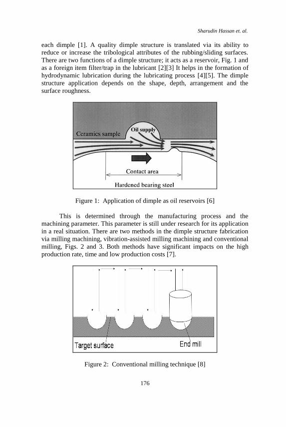
each dimple [1]. A quality dimple structure is translated via its ability to
reduce or increase the tribological attributes of the rubbing/sliding surfaces.
There are two functions of a dimple structure; it acts as a reservoir, Fig. 1 and
as a foreign item filter/trap in the lubricant [2][3] It helps in the formation of
hydrodynamic lubrication during the lubricating process [4][5]. The dimple
structure application depends on the shape, depth, arrangement and the
surface roughness.
Figure 1: Application of dimple as oil reservoirs [6]
This is determined through the manufacturing process and the
machining parameter. This parameter is still under research for its application
in a real situation. There are two methods in the dimple structure fabrication
via milling machining, vibration-assisted milling machining and conventional
milling, Figs. 2 and 3. Both methods have significant impacts on the high
production rate, time and low production costs [7].
Figure 2: Conventional milling technique [8]
A Review of the Milling Process to Fabricate a Dimple Structure
177
Figure 3: Vibration-assisted milling machining [9]
Milling Dimple Structure Process
The dimple structure production process has been extensively used in several
earlier reports. This has been due to the milling process being a flexible
process, which uses a combination of various cutting techniques and cutting
tool geometry that is able to produce various dimple structures on the
working material [10]. In conventional industry, the dimple structure is
produced on a large scale via the photolithographic technique, plastic
formation process and milling [11][12][13]. According to Shinichi et al., [14]
the conventional milling is a movement of the cutting tool in a vertical or a
horizontal direction that produces the dimple structure. This technique is very
time consuming. There are many factors that support the use of the milling
process for the production of a dimple structure. Some of them are - a high
disposal of the working material, accurate surface neatness and applications
using various working materials [10]. Besides, the milling process can
produce various dimple structures by simply changing the cutting techniques
[10]. Takashi et al. have studied the effect of the slope of the cutting tool on
the dimple structure surface via simulation and experimentation [15]. It was
discovered that while the slope and the depth of the cutting tool were lesser
than its radius, there was no cutting on the working material. Besides, a high
feed rate could prevent overlapping of the dimple structure during the
machining process [7]. The combination of the cutting tool movement in a
vertical or a horizontal direction along with a high feeding rate during the
milling process could produce a dimple structure on the working material
surface [8]. A dimple structure fabrication process using the conventional
milling is very time consuming. Moreover, a constant movement of the
cutting tool will cause a deterioration of the cutting accuracy [8]. Hence, a
new technique needs to be developed in order to produce a high-accuracy
dimple structure
Sharudin Hassan et. al.
178
Table 1: Milling machining methods and their effect on the surface tribology.
RESEARCHER YEAR METHOD FINDING
Taposh et al. 2015 Micro
drilling
Dimple structure could reduce
22% friction and 53% erosion on
the hip joint.
Taposh et al. 2014 Micro
drilling
To investigate any mechanical
change and the presence of wear
particles during the dimple
fabrication process using micro
tooling.
Micro dimple fabrication process
succeeded without any damage
on the mechanical attributes
Eldon et al. 2013 Micro
milling
Surface texture produced on a
bigger surface will be valued for
its effectiveness on the
tribological attributes.
Machining method to produce a
dimple was a viable method
Shinichi et al.
2008 Milling Suggested the use of a machining
centre to fabricate the dimple
structure.
Dimple structure could be
fabricated on a metal surface
using a sub-millimetre ball end
mill.
Jiwang et al. 2010 Milling Investigated the performance of
a ball end mill cutting through
the surface roughness and
accurate machining of working
material and cutting tool erosion
attributes.
Cutting performance depends on
the direction of the cutting tool
feeding rate.
Takashi et al. 2014 Milling When the slope of the cutting
tool and its depth was less than
A Review of the Milling Process to Fabricate a Dimple Structure
179
its radius, no cutting took place
on the machining.
No overlapping occurred at a
high feeding rate.
Shinichi et al. 2015 Milling New technique to fabricate a
dimple via milling using the end
mill tooling.
Able to estimate a dimple
geometry via the horizontal
movement of a cutting tool
Takashi et al. 2013 Milling New mechanistic model
developed to control the form
and dimple structure alignment.
Develop an error model to
estimate the machining accuracy.
Testifying Error Model and
mechanistic via simulation
Jesus et al. 2015 Milling Effect of friction direction on
textured aluminium surface.
Sliding reaction does not depend
on the friction direction from its
coefficient friction
Table 1 showed the machining process by previous researchers
focusing on cutting tool and machining parameters to produce a dimple
structure on the working material surface. These two aspects are dominant in
fabricating the dimple structure in order to improve the surface tribology
attributes
Vibration-assisted Machining (VAM) Process
The VAM was a machining method that was first applied by the industry in
1950, in the micro scale metal-cutting applications [16][17]. However, its use
was still limited, and research focused more towards an understanding of the
VAM basic concept. In mid-1980, VAM was deeply researched on steel,
glass and ceramic materials. As a result of using the VAM, the lifespan of the
cutting tool and surface roughness could be increased [16]. It is a machining
method where both the amplitude and the frequency are exposed to a cutting
Sharudin Hassan et. al.
180
tool or the working table while the working material cutting process is taking
place [18]. Low amplitude value and high frequency are used during the
working material cutting process [16]. The combination of the cutting speed,
amplitude and suitable frequency could reduce the machining force and this
will result in accurate surface neatness, high accuracy approaching zero burrs
as compared to the conventional machining [19]. The cutting tool life span
could be increased with the use of the VAM process during fragile and
ferrous working material cutting [19]. There are two types of VAM processes
in fabricating the dimple structure; 1-Dimension and 2-Dimension, as
mentioned in Fig. 4 [20][21].
Figure 4: Type of VAM
Table 2: Vibration Assisted Machining Method and its
Effect on the Tribology Surface
RESEARCHER YEAR METHOD FINDING
Xuehui and
Jianhua
2013 Ultrasonic
Vibration
assisted
milling
(UVAM)
Studied tribology attributes on
the surface texture produced
through UVAM method.
Experimental results showed
that the UVAM force could
change morphology of the
surface machined
Rendi
Kurniawan and
2014 Elliptical
vibration
Design new tool holder for
fabricating the dimple
VAM - Milling
2D VAM 1D VAM
Resonant
F= 20 – 40kHz
Amp = 3 - 100μm Resonant
F= 20 – 40kHz
Tool path = 3μm x 3μm to
- 3μm x 3μm
Non Resonant
F= ≤ 1kHz
Tool path = 5μm x
4μm
A Review of the Milling Process to Fabricate a Dimple Structure
181
Tae Jo Ko machining
(EVM)
structure
Micro dimples and grooves
have been successfully built
using a new tool holder
Hui Ding et al. 2010 Two
dimensional
Vibration
Assisted
Micro Enn
Milling (2-D
VAMEM)
2D VAMEM was produced for
the hardened tool steel
machining
Researched vibration
parameter effect on the surface
roughness and cutting tool
wear off
2DVAMEM could be used in
making a mould or dice where
it could increase the machining
competency, surface quality
and cutting tool life span
Xue and Guo 2015 Ultrasonic
Vibration
Assisted
Milling
(UVAM)
Two surfaces micro texture
such as Micro Scale Texture
(MST) and Micro Furrow
Texture (MFT) were produced
via the UVAM.
The behaviour of MST and
MFT were analysed with
lubricant oil in the sliding
position and compared to the
non-texture surface.
UVAM could increase the
MST and MFT surface
roughness as compared to the
non-texture surface.
MFT was better as compared
to MST
UVAM could increase the
tribology attributes especially
bearing capacity and resistance
wear off.
Sharudin Hassan et. al.
182
Lian et al. 2013 Ultrasonic
Vibration
Assisted
Milling
(UVAM)
UVAM investigated the
surface roughness Al6061 with
vibration and without
vibration.
Amplitude Ultrasonic
vibration gave an optimum
value on the Al6061 surface
roughness.
Xue et al 2012 Ultrasonic
Vibration
Assisted
Milling
(UVAM)
Investigated the UVAM effect
in micro end milling
machining.
Compared the cutting force
effect, chip formation, surface
topography and machining
dimension accuracy.
Chip formation with vibration
in feeding direction, is small
and consistent
UVAM in feeding direction
has negative effect on surface
roughness and positive on
dimension accuracy.
Xiaoling and
Boyuan
2015 2D Vibration
Assisted
micro
milling (2D
VAMM)
Researched the vibration
direction effect, vibration
amplitude and frequency on
the surface roughness.
Vibration in the normal
direction has great impact in
increasing the surface quality.
Ding et al. 2010 2D Vibration
Assisted
micro end
milling (2D
VAMEM)
Model 3D cutting force by 2D
VAMEM was analysed.
Two models were taken to test
the amplitude effect at the
maximum level cutting force
and average level cutting force
A Review of the Milling Process to Fabricate a Dimple Structure
183
The cutting outcome using UAM has become the main focus in
improving the surface tribology attributes as compared to the milling
machining process to produce a dimple structure. The vibration and
amplitude produced from the VAM process have a real impact on the
working material surface.
Figure 5: Mode of machining in the conventional and 2-D VAM milling [20]
Nowadays, the VAM method has been widely used in composite and
optic glass and is hard to machine [9]. It is because the consistent overlapping
route of the cutting tool will produce thin chips every time the cutting occurs
and this will reduce the cutting force and heat. According to Masahiko et al.,
the heat generated during the cutting process could be reduced by using a
vibration assisted technique. Fig. 5 showed the comparison between the
conventional machining and 2D VAM milling process [20]. The effect of 2D
VAM cutting technique could increase the material disposal rate and increase
the machining competency from the production time, rate and cost aspects,
Fig. 6.
Figure 6: Types of VAM based on the modes of vibration (a) 1-Dimensional
VAM, (b) 2-Dimensional VAM [20]
Sharudin Hassan et. al.
184
One Dimensional 1D Vibration Assisted Method
This is the first method used in machining to produce a dimple structure. This
method consists of two types of cutting tool moves which are parallel to the
Z-axis or the working table movement parallel to the Z-axis to produce a
dimple structure, Fig 6
Figure 7: The principle schematic diagram of VAM [9]
The most studied method fabricates the dimples by moving the working
table, Fig. 8. The working table is moved by a certain frequency value to
produce dimples. However, the dimple structure accuracy also depends on
the macro geometry angle of the cutting tool, feeding rate and axis movement
speed ratio along with cutting speed [22].
(a) Illustration (b) Photo
Figure 8: Fabricating setup a: Illustration b Photo [18]
Spindle
Milling cutter
Workpiece Vibrator
Fixture
Workbench
Spindle
Milling cutter
Workpiece
Fixture
Vibrator
A Review of the Milling Process to Fabricate a Dimple Structure
185
Two Dimensional (2D) Vibration Assisted Method
This method was developed after the 1-D VAM process had been widely
used to produce the dimple structure. A 2-D VAM concept was first
introduced in 1990, with the objective to reduce the force and the lifespan of
the cutting tool surpassing the performance of 1-D VAM process
[16][23][24]. In this method, the cutting tool moves along the X-axis and Z-
axis while cutting the working material. It is also known as elliptical motion
cutting [21], based on the movement while the cutting occurs. Most of the
assisted tooling was focused on the cutting tool movement rather than the
working table. According to Chang et al., the 2-D cutting technique could
decrease the cutting performance where the cutting tool wear-off could be
reduced and the machining accuracy could be increased during alloy
machining Al 6061 [25]. Ding et al., discovered that during the HRC 55 and
HRC58 hardened tool steel machining, the 2-D technique could reduce 5 -
20% of the tool wear as compared to the conventional method [26]. The use
of the 2-D cutting technique can reduce the cutting force, improve surface
neatness, prolong the cutting tool lifespan and is able to cut fragile and hard
machine materials [27][28][29]. The research carried out by Rendi et al.,
found that a correct plane surface and low surface roughness were produced
by using the 2-D vibration assisted tool that was developed [30].Ding et al.,
[26] discovered the HRC tool steel (without vibration) roughness value of
0.53 μm, as compared to 0.15 μm with vibration. Besides, the frequency and
amplitude also affects the material surface roughness. The research by
Xioling and Boyuan found that by reducing the waviness on the machined
surface, the surface roughness could be reduced [31]. Their research found
that the vibration assisted in a normal direction was the main factor in
increasing the quality of surface machined. The 2-D machining was used
mainly for the development of a cutting tool holder in order to generate a 2-
dimensional movement in the working material cutting. The Piezoactuator
was the main component to generate a 2D movement. This movement is sent
to the cutting tool while the milling process is taking place. However, a high
dynamic movement during the operation can cause a generation of heat on
the actuator ring [22]. The heat effect will result in the deterioration of the
machining accuracy.
Cutting Process in the Vibration Assisted Milling
The phenomenon of controlling the vibration during machining is an
approach to increase the machining efficiency. The cutting tool vibration
along the elliptical trajectory will form a dimple structure on the working
material surface [32], Fig. 9. According to Shen et al., the vibration parameter
Sharudin Hassan et. al.
186
and machining were controlled in order to form a geometry morphology scale
during the machining process [33]. Ping et al., stated that the surface form
and the texture pattern depend on the vibration trajectory form, cutting speed,
feeding rate and the cutting tool geometry.
Figure 9: A Schematic representation of the elliptical vibration texturing
process [32]
By applying the vibration on the cutting tool during the machining
process, the quality of the surface machined is increased. The quality of the
machining can be upgraded by applying a high-frequency vibration during
the cutting process [34]. During the 2-D cutting process, the loss of the
cutting tool consistent touch on the working material surface will reduce the
cutting force, vibration and the cutting zone temperature [25][34]. Lian et al.,
[9], stated that the Hammer effect existed during the UVAM process when
the cutting tooth constantly hit the working material at high frequencies. This
would cause a thin chip formation and could avoid the formation of micro
cracks on the working material surface and cutting
edge [34]. Takashi et al., found that the dimple machining occurred at
a certain slope of the cutting tool with a high feeding rate. No material cutting
occurred when the cutting tool slope and its depth were less than its radius
during a cutting circuit [35].
Application on Flat Surface
The global demand for cost saving and high-performance vehicles has
recently become the main issue for all the car manufacturers. Almost 2/3rd of
the engine performance loss was caused by vibration and wear off, Fig 10
and Fig 11
A Review of the Milling Process to Fabricate a Dimple Structure
187
Figure 10: Mechanical losses distribution in an internal combustion engine
[36].
Figure 11: Breakdown of the passenger car energy consumption [37]
To meet the global demand, the vibration source and wear-off need to
be minimised primarily. A surface structure like dimple has been identified as
one of the solutions [36][38]. According to Ryk et al., [39], it was discovered
that the micro dimple on the piston ring surface could reduce the friction by
25%. According to Sapawe et al.,[40] , the main issue in the mechanical
system is to reduce wear and friction are the main focus of researchers. The
Sharudin Hassan et. al.
188
reduction of wear and friction will be an impact on the fuel consumption and
energy competency of the vehicles. In other words, billions of dollars per
year could be saved if the component life can be enhanced by understanding
the characteristics and the ability to reduce and control the wear and friction.
These two aspects have become the main focus in the global automotive
industry where the manufacturing technique and the surface geometry need
specific attention [41]. According to Lawes et al., [38], an increase in the
engine competency played a main role in the reduction of the CO2 global
disposal through better fuel saving for the customers. According to Eldon and
Jesus [41][42], the value of the friction coefficient on the non-dimple surface
is higher when compared to the surface with a dimple in both the cases, with
or without lubrication. The application of the dimple structure in real-life
situations is limited. So far, studies are still at their experimental level.
Research on the flat surface was done using the fabricating machine guide
ways. Yukeng et al., discovered that a dimple structure acted as an oil
reservoir on the guideways and had effectively reduced the maximum
pressure touch during sliding [43]. The dimple structure could also generate a
hydrodynamic pressure in the surrounding environment and this would widen
the hydrodynamic lubrication regime of the guideways surface [44][45][46].
The research in the automotive industry is mainly focused on the cylindrical
surface component rather than the flat component. Shim surface on the valve
train is a flat surface that contributes to 10% of the friction losses. The Fig.
10 is still not fully explored with respect to the surface texture aspect.
Components like 'shim' have an impact on the vehicle engine performance in
the case of a wear off.
Conclusion
The machining process via a VAM for fabrication of the dimple is still at the
research level and needs to be studied and applied in the real situations of
friction and wear off. Its objective is to observe the effectiveness of dimple
structure, acting as a reservoir and a foreign item filter in the lubricant.
Generally, a dimple structure can be produced by using this process. Most
studies on the production of a dimple were mainly focused on the table
movement and comparatively fewer studies focused on the cutting tool. The
complication in applying the VAM process on the cutting tool needs further
study. The surface roughness resulting due to the dimple structure needs to be
upgraded since surface roughness is a main aspect in tribology. This is vital
in upgrading the material tribology attributes based on its application in the
automotive industry which is more challenging along with meeting the global
demand. Besides, a low-frequency machining for producing the dimple
A Review of the Milling Process to Fabricate a Dimple Structure
189
structure needs to be explored further to determine the effect of its use on the
dimple structure.
References
[1] Roy, T., Choudhury, D., Ghosh, S., Mamat, A. B., & Pingguan-
Murphy, B. "Improved friction and wear performance of micro dimpled
ceramic-on-ceramic interface for hip joint arthroplasty." Ceramics
International 41.1 (2015): 681-690.
[2] Pettersson, Ulrika, and Staffan Jacobson. "Friction and wear properties
of micro textured DLC coated surfaces in boundary lubricated
sliding."Tribology letters 17.3 (2004): 553-559.
[3] Suh, A. Y., S-C. Lee, and A. A. Polycarpou. "Adhesion and friction
evaluation of textured slider surfaces in ultra-low flying head-disk
interfaces."Tribology Letters 17.4 (2004): 739-749.
[4] Nanbu, T., Yasuda, Y., Ushijima, K., Watanabe, J., & Zhu, D. "Increase
of traction coefficient due to surface microtexture." Tribology
Letters 29.2 (2008): 105-118.
[5] Wakuda, M., Yamauchi, Y., Kanzaki, S., & Yasuda, Y. "Effect of
surface texturing on friction reduction between ceramic and steel
materials under lubricated sliding contact." Wear254.3 (2003): 356-363.
[6] Uehara, Y., Wakuda, M., Yamauchi, Y., Kanzaki, S., & Sakaguchi, S.
"Tribological properties of dimpled silicon nitride under oil
lubrication." Journal of the European Ceramic society 24.2 (2004):
369-373.
[7] Matsumura, Takashi, Ryosuke Watanabe, and Yuji Musha. "An Error
Model in Micro Dimple Milling." Key Engineering Materials. Vol. 554.
Trans Tech Publications, 2013.
[8] Kogusu, Shinichi, Takakazu Ishimatsu, and Yasuhiko Ougiya.
"Efficient generation of dimpled surface using milling
process." International Workshop and Conference on Photonics and
Nanotechnology 2007. International Society for Optics and Photonics,
2007.
[9] Lian, H., Guo, Z., Huang, Z., Tang, Y., & Song, J. "Experimental
research of Al6061 on ultrasonic vibration assisted micro-
milling." Procedia CIRP 6 (2013): 561-564.
[10] Yan, J., Zhang, Z., Kuriyagawa, T., & Gonda, H. "Fabricating micro-
structured surface by using single-crystalline diamond endmill." The
International Journal of Advanced Manufacturing Technology 51.9-12
(2010): 957-964.
[11] Moronuki, Nobuyuki, Daisuke Nishi, and Kenji Uchiyama. "Textured
Surface Produced by Anisotropic Etching of Silicon and Its Frictional
Properties."Initiatives of Precision Engineering at the Beginning of a
Sharudin Hassan et. al.
190
Millennium. Springer US, 2002. 132-136.
[12] Kim, Joonwon, and Chang-Jin CJ Kim. "Nanostructured surfaces for
dramatic reduction of flow resistance in droplet-based
microfluidics."Proceedings, IEEE micro electro mechanical systems.
2002.
[13] Etsion, Izhak. "State of the art in laser surface texturing." Journal of
tribology 127.1 (2005): 248-253.
[14] Kogusu, S., Ishimatsu, T., Ougiya, Y., Yazawa, T., & Moromugi, S.
"Decoration of metal surface by dimples using ball-end milling
process." Industrial Technology, 2008. ICIT 2008. IEEE International
Conference on. IEEE, 2008.
[15] Matsumura, Takashi, and Satoru Takahashi. "Machining of micro
dimples in milling for functional surfaces." THE 14TH
INTERNATIONAL ESAFORM CONFERENCE ON MATERIAL
FORMING: ESAFORM 2011. Vol. 1353. No. 1. AIP Publishing, 2011.
[16] Brehl, D. E., and T. A. Dow. "Review of vibration-assisted machining
methods for precision fabrication." North Carolina State University
Raleigh, North Carolina, USA (2006).
[17] Skelton, Ralph Conway. "Turning with an oscillating
tool." International Journal of Machine Tool Design and Research 8.4
(1968): 239-259.
[18] Shen, Xue-Hui, and Guo-Can Tao. "Tribological behaviors of two
micro textured surfaces generated by vibrating milling under boundary
lubricated sliding." The International Journal of Advanced
Manufacturing Technology79.9-12 (2015): 1995-2002.
[19] Abdur-Rasheed, Alao. "A fundamental study of vibration assisted
machining." Advanced Materials Research. Vol. 264. Trans Tech
Publications, 2011.
[20] Kumar, M. N., Subbu, S. K., Krishna, P. V., & Venugopal, A.
"Vibration assisted conventional and advanced machining: A
review." Procedia Engineering 97 (2014): 1577-1586.
[21] Brehl, D. E., and T. A. Dow. "Review of vibration-assisted
machining."Precision engineering 32.3 (2008): 153-172.
[22] Köhler, J., and A. Seibel. "FTS-based face milling of micro
structures."Procedia CIRP 28 (2015): 58-63.
[23] Moriwaki, Toshimichi, and Eiji Shamoto. "Ultraprecision diamond
turning of stainless steel by applying ultrasonic vibration." CIRP
Annals-Manufacturing Technology 40.1 (1991): 559-562.
[24] Cerniway, Matthew Allen. "Elliptical diamond milling: kinematics,
force and tool wear." (2002).
[25] Chern, Gwo-Lianq, and Yuan-Chin Chang. "Using two-dimensional
vibration cutting for micro-milling." International Journal of Machine
Tools and Manufacture 46.6 (2006): 659-666.
A Review of the Milling Process to Fabricate a Dimple Structure
191
[26] Ding, H., Ibrahim, R., Cheng, K., & Chen, S. J. "Experimental study on
machinability improvement of hardened tool steel using two
dimensional vibration-assisted micro-end-milling." International
Journal of Machine Tools and Manufacture 50.12 (2010): 1115-1118.
[27] Shamoto, Eiji, and Toshimichi Moriwaki. "Ultaprecision diamond
cutting of hardened steel by applying elliptical vibration cutting." CIRP
Annals-Manufacturing Technology 48.1 (1999): 441-444.
[28] Moriwaki, Toshimichi, and Eiji Shamoto. "Ultrasonic elliptical
vibration cutting." CIRP Annals-Manufacturing Technology 44.1
(1995): 31-34.
[29] Suzuki, N., Haritani, M., Yang, J. B., Hino, R., & Shamoto, E.
"Elliptical vibration cutting of tungsten alloy molds for optical glass
parts." CIRP Annals-Manufacturing Technology 56.1 (2007): 127-130.
[30] Kurniawan, Rendi, and Tae Jo Ko. "A new tool holder design with two-
dimensional motion for fabricating micro-dimple and groove
patterns."International journal of precision engineering and
manufacturing 15.6 (2014): 1165-1171.
[31] Jin, Xiaoliang, and Boyuan Xie. "Experimental study on surface
generation in vibration-assisted micro-milling of glass." The
International Journal of Advanced Manufacturing Technology 81.1-4
(2015): 507-512.
[32] Guo, Ping, and Kornel F. Ehmann. "An analysis of the surface
generation mechanics of the elliptical vibration texturing
process." International Journal of Machine Tools and Manufacture 64
(2013): 85-95.
[33] Shen, X. H., Zhang, J., Xing, D. X., & Zhao, Y. "A study of surface
roughness variation in ultrasonic vibration-assisted milling." The
International Journal of Advanced Manufacturing Technology 58.5-8
(2012): 553-561.
[34] Ostasevicius, V., Gaidys, R., Dauksevicius, R., & Mikuckyte, S. "Study
of vibration milling for improving surface finish of difficult-to-cut
materials." Strojniški vestnik-Journal of Mechanical Engineering 59.6
(2013): 351-357.
[35] Matsumura, T., Takahashi, S., Nagase, N., & Musha, Y. "Micro Dimple
Milling for Structured Surface."Advanced Materials Research. Vol.
966. Trans Tech Publications, 2014.
[36] Holmberg, Kenneth, Peter Andersson, and Ali Erdemir. "Global energy
consumption due to friction in passenger cars." Tribology
International 47 (2012): 221-234.
[37] Taylor, C. M. "Automobile engine tribology—design considerations for
efficiency and durability." Wear 221.1 (1998): 1-8.
[38] Lawes, S. D. A., Sarah V. Hainsworth, and M. E. Fitzpatrick. "Impact
wear testing of diamond-like carbon films for engine valve-tappet
Sharudin Hassan et. al.
192
surfaces." Wear268.11 (2010): 1303-1308.
[39] Etsion, Izhak. "Improving tribological performance of mechanical
components by laser surface texturing." Tribology letters 17.4 (2004):
733-737.
[40] Sapawe, N., Syahrullail, S., & Izhan, M. I. "Evaluation on the
tribological properties of palm olein in different loads applied using
pin-on-disk tribotester." Journal Tribologi 3 (2014): 11-29.
[41] Graham, Eldon, Chaneel I. Park, and Simon S. Park. "Fabrication of
micro-dimpled surfaces through micro ball end milling." International
Journal of Precision Engineering and Manufacturing 14.9 (2013):
1637-1646.
[42] Resendiz, J., Graham, E., Egberts, P., & Park, S. S. "Directional friction
surfaces through asymmetrically shaped dimpled surfaces patterned
using inclined flat end milling." Tribology International 91 (2015): 67-
73.
[43] Yukeng, H., Darong, C. and Linqingt, Z. 1985. On Their Tribological
Behaviour . Butterworth & Co (Publishers) Ltd. 125–129
[44] Nakano, M., Korenaga, A., Korenaga, A., Miyake, K., Murakami, T.,
Ando, Y., ... & Sasaki, S. "Applying micro-texture to cast iron surfaces
to reduce the friction coefficient under lubricated conditions." Tribology
Letters 28.2 (2007): 131-137.
[45] Ryk, G., Y. Kligerman, and Izhak Etsion. "Experimental investigation
of laser surface texturing for reciprocating automotive
components." Tribology Transactions 45.4 (2002): 444-449.
[46] Ronen, Aviram, Izhak Etsion, and Yuri Kligerman. "Friction-reducing
surface-texturing in reciprocating automotive components." Tribology
Transactions 44.3 (2001): 359-366.