154
JSS-296 MF/HF RADIO EQUIPMENT INSTRUCTION MANUAL

JSS-296MF/HF RADIO EQUIPMENT
INSTRUCTIONMANUAL
Nittochi Nishi-Shinjuku bldg.10-1, Nishi-Shinjuku 6-chome, Shinjuku-ku, Tokyo 160-8328 JAPANPhone : +81-3-3348-0151Fax : +81-3-3348-3648
1-1, Shimorenjaku 5-chome, Mitaka-shi, Tokyo 181-8510 JAPANPhone : +81-422-45-9111Fax : +81-422-45-9110
HEAD OFFICE & SALES DEPT.
MAIN PLANT
For further information contact:
Since 1915
CODE NO. 7ZPJD0162 JRC
EDITION 2 JAN. 2003
MF
/HF
RA
DIO
EQ
UIP
ME
NT
INS
TR
UC
TIO
N M
AN
UA
LJS
S-296

blank

i
CAUTIONS AGAINST HIGH VOLTAGE
Radio and radar devices are operated by high voltages of anywhere from a few hundred volts up to manyhundreds of thousands of volts. Although there is no danger with normal use, it is very dangerous if contactis made with the internal parts of these devices. (Only specialists should attempt any maintenance,checking or adjusting.)There is a very high risk of death by even a few thousand volts, in some cases you can be fatallyelectrocuted by just a few hundred volts. To circumvent accidents, you should avoid contact with theinternal parts of these devices at all costs. If contact is inevitable as in the case of an emergency, you mustswitch off the devices and ground a terminal in order to discharge the capacitors. After making certain thatall the electricity is discharged, only then can you insert your hand into the device. Wearing cotton glovesand putting your free hand in your pocket, in order not to use both hands simultaneously, are also verygood methods of shock prevention.Quite often, an injury occurs by secondary factors, therefore it is necessary to choose a sturdy and levelworking surface. If someone is electrocuted it is necessary to thoroughly disinfect the affected area andseek medical attention as soon as possible.
Cautions concerning treatment of electrocution victims
When you find an electrocution victim, you must first switch off the machinery and ground all circuits. If youare unable to cut off the machinery, move the victim away from it using a non-conductive material such asdry boards or clothing.When someone is electrocuted, and the electrical current reaches the breathing synapses of the centralnervous system inside the brain, breathing stops. If the victim's condition is stable, he or she can beadministered artificial respiration. An electrocution victim becomes very pale, and their pulse can be veryweak or even stop, consequently losing consciousness and becoming stiff.Administration of first aid is critical in this situation.

ii
First aid
☆Note points for first aid
Unless there is impending danger leave the victim where he or she is, then begin artificial respiration.Once you begin artificial respiration, you must continue without losing rhythm.
(1) Make contact with the victim cautiously, there is a risk that you may get electrocuted.
(2) Switch off the machinery and then move the victim away slowly if you must.
(3) Inform someone immediately (a hospital or doctor, dial emergency numbers, etc.).
(4) Lay the victim on his or her back and loosen any constrictive clothing (a tie, or belt).
(5) (a) Check the victim's pulse.(b) Check for a heartbeat by pressing your ear against the victim's chest.(c) Check if the victim is breathing by putting the back of your hand or face near the victim's face.(d) Check the pupils of the eyes.
(6) Open the victim's mouth and remove any artificial dentifrice, food or chewing gum. Leave the mouthopened and flatten the tongue with a towel or by putting something into the mouth to prevent thevictim's tongue from obstructing the throat. (If he or she is clenching their teeth and it is difficult toopen the mouth, use a spoon or the like to pry open the mouth.)
(7) Continually wipe the mouth to prevent the accumulation of saliva.

iii
☆If the victim has a pulse but is not breathing("Mouth to mouth" resuscitation) Figure 1.
(1) Place the victim's head facing backward (place something under the neck like a pillow).(2) Point the chin upward to widen the trachea.(3) Pinch the victim's nose, take a deep breath, then put your mouth over the victim's mouth and exhale
completely, making sure that your mouth completely covers the victim's mouth. Then remove yourmouth. Repeat this routine 10 to 15 times per minute (holding the nostrils).
(4) Pay attention to the victim to notice if he or she starts to breath. If breathing returns, stopresuscitation.
(5) If it is impossible to open the victim's mouth, put something like a plastic straw or vinyl tube into one ofthe nostrils then blow air in while covering the mouth and the other nostril.
(6) Occasionally, when the victim comes back to consciousness, they immediately try to stand up.Prevent this and keep them in a laying position. Give them something warm to drink and be sure thatthey rest (do not give them any alcohol).
Administering artificial respiration by raising the head.
(1) Raise the back of the head, then place onehand on the forehead and place the otherhand under the neck.Most victims open their mouth when doing this,making "mouth to mouth" resuscitation easier.
(2) Cover the victim's mouth by opening yourmouth widely, then push your cheek againstthe victim's nose, or pinch the victim's nose to prevent air fromleaking out of it.
(3) Completely exhale into the lungs.Exhale into the lungs until the chest is inflates.You have to blow as rapidly as possible for thefirst 10 times.
("Mouth to mouth" resuscitation) Figure 1.

iv
☆If the victim has no pulse and is not breathing(Heart massage in combination with artificial respiration.) Figure 2
If the victim has no pulse, his or her pupils are dilated, and if you cannot detect a heartbeat, the heart mayhave stopped, beginning artificial respiration is critical.
(1) Put both hands on the diaphragm, with hands on top of each other keeping both arms straight. (If yourelbows are bent, you cannot push with as much power.) Press the diaphragm with your body weightuntil the chest sinks about 2 cm (about 50 times per minute).
(2) If administering first aid when alone:Perform the heart massage about 15 times then blow in twice. Repeat this routine.If administering first aid with two people:One person performs the heart massage 5 times, and the other person blows air in once. Repeat thisroutine. (Heart massage and "mouth to mouth" resuscitation used together.)
(3) Constantly check the pupils and the pulse, if the pupils become normal and the pulse steadies, keepthem in a laying position and give them something warm to drink, be sure that they rest (do not givethem any alcohol.). In any case you have to entrust major decision making to a doctor. Havingunderstanding people around is essential to the victim's recovery from the mental shock ofelectrocution.
(Heart massage in combination with artificial respiration.) Figure 2

v
PrefaceThank you for purchasing JRC MF/HF Radio Equipment model JSS-296.
For best operation and performance results, read this manual thoroughly before use. Keep this manual in a convenient place for future reference. Make use of this manual when
experiencing operation difficulties.

vi
WARNING
Before OperationConcerning the symbols
This manual uses the following symbols to explain correct operation and to prevent injury ordamage to property. The symbols and descriptions are as follows. Understand them beforeproceeding with reading this manual.
Indicates a warning that, if ignored,may result in serious injury or evendeath.
Indicates a caution that, if ignored,may result in injury or damage toproperty.
Examples of symbols
The symbol indicates caution (including DANGER and WARNING). Theillustration inside the symbol specifies the content of the caution moreaccurately. (This example is a general caution.)
The symbol indicates that performing an action is prohibited. The illustrationinside or next to the symbol specifies the contents of the prohibited operation.(In this example, disassembly is prohibited.)
The ● symbol indicates operations that must be performed. The illustrationinside the ● symbol specifies the obligatory operation. (In the example,unplugging is the obligatory operation.)
Concerning warning labelsA warning label is pasted to the top cover of this product.Do not remove, damage, or modify the label.
CAUTION

vii
Handling Precautions
WARNINGDo not disassemble or modify this unit. Doing so may cause fire, electrical shock, or failure.
Do not use a voltage other than specified. Doing so may cause fire, electrical shock, or failure.
If you remove a unit, be sure to store it in a non-conductive bag. If you wrap It up with materials such as aluminum foil, the back-up power supply may Short circuit and the ICs may be damaged.
There are no user-serviceable parts inside this equipment. Inspection or maintenance by unauthorized persons may result in fire or electric shock.For inspection and maintenance, contact JRC or its authorized agents.

viii
Handling Precautions
CAUTIONDo not use this equipment in an environment other than that specified.Doing so may cause failure or malfunction.
Do not turn the trimmer resistors or trimmer capacitors on the PCB unit (they arepreset at the factory). Doing so may cause failure or malfunction.
Do not install the equipment in a place near water or in one with excessivehumidity, steam, dust or soot. Doing so may cause fire, electric shock, or failure.
Do not get this equipment wet or spill any liquids on or near this equipment. Doingso may cause electrical shock or failure.
Do not place this equipment anywhere vibration or impact is likely to occur. Doingso may cause a failure or injury.
Do not place anything on top of this equipment. Doing so may cause fire or failure.
Leave installation of this equipment to JRC or our agents. Installation by anunauthorized person may lead to malfunction.
Be sure to turn OFF the printer’s power when opening and closing the printercover.Failure to comply could result in electrical shock, failure, or injury.
Just after printing, the temperature of the printing head is high.Do not touch the printing head until the temperature goes down.Doing so may cause a burn or an injury.
Do not touch any part of the cutter.Doing so is potentially dangerous.

ix
DISTRESS CALL Transmissible Address : XXXXXXXXX Nature : UNDESIGNATED DISTDist-position : 12゚34’N123゚45’E
Dist-UTC : 01:26 Dist-telecomm : J3E TEL End of sequence: EOS Call TX/RX freq: 2,187.5/ 2,187.5 kHz
DDIISSTTRREESSSS CCAALLLLSSNCT-196N
There are three methods of transmitting a distresscall. These methods are described below in orderof ease of use, with the easiest first.
Transmitting Distress Calls 1 Procedure
1. Open the cover on the left and press .The following screen is displayed.
• If stop the distress transmission, press .
2. Press for 3.5 seconds continuously.
• If stop the distress transmission, release .
3. The following screen is displayed and the distress transmission is started.If a printer is connected, it prints out the distress message.The distress message is transmitted for 5 times successively.
• If break the distress transmission, press .STOP
DISTRESS CALL Transmitting TX frequency : 2,187.5 kHz TX date&time :06.Sep.2001(Thu) 01:26 1/5
Note
DISTRESS
DISTRESS
DISTRESS
Note
STOP
Note

x
4. When the distress transmission is completed, the screen is displayed as follows for afew seconds.
5. The distress transmission is repeated at random intervals of 3.5 to 4.5 minutes.On completion of the transmission, the screen is changed as follows. And the distresstransmission is repeated when the displayed time has counted down to zero.
DISTRESS CALL 2,187.5 kHz
NEXT DISTRESS CALL : AFTER 3.0 min
DISTRESS CALL Send Completed TX frequency : 2,187.5 kHz TX date&time :06.Sep.2001(Thu) 01:27 5/5

xi
DISTRESS CALL Transmissible Address : XXXXXXXXX Nature : UNDESIGNATED DISTDist-position : 12゚34’N123゚45’E
Dist-UTC : 01:26 Dist-telecomm : J3E TEL End of sequence: EOS Call TX/RX freq: 2,187.5/ 2,187.5 kHz
Transmitting Distress Calls 2
Front panel
Procedure
1. Press or .
2. Open the cover on the left and press .The following screen is displayed.
• If stop the distress transmission, press .
3. Press for 3.5 seconds at least.
• If stop the distress transmission, release .
4. The following screen is displayed and the distress transmission is started.If a printer is connected, it prints out the distress message.The distress message is transmitted for 5 times successively.
• If break the distress transmission, press .
2187.5kHz 8414.5kHz
DISTRESS CALL Transmitting TX frequency : 2,187.5 kHz TX date&time :06.Sep.2001(Thu) 01:26 1/5
Note
DISTRESS
DISTRESS
Note
STOP
Note
DISTRESS
STOP

xii
5. When the distress transmission is completed, the screen is displayed as follows for afew seconds.
6. The distress transmission is repeated at random intervals of 3.5 to 4.5 minutes.On completion of the transmission, the screen is changed as follows. And the distress transmissionis repeated when the displayed time has counted down to zero.
DISTRESS CALL 2,187.5 kHz
NEXT DISTRESS CALL : AFTER 3.0 min
DISTRESS CALL Send Completed TX frequency : 2,187.5 kHz TX date&time :06.Sep.2001(Thu) 01:27 5/5

xiii
Transmitting Distress Calls 3The NCT-196N enables an operator to create and edit messages for transmission.
Procedure1. Confirm that the "DSC watching" screen is displayed.
2. Press .The "MENU #1-EDIT&CALL" screen is displayed.
3. Press and then to select “3. Distress call”.The "Distress Call" screen is displayed as follows. Then setup these items except for “Address”and “End of sequence” properly.
4. Open the cover on the left and press for 3.5 seconds at least.
5. The following screen is displayed and the distress transmission is started.If a printer is connected, it prints out the distress message.The distress message is transmitted for 5 times successively.
• If break the distress transmission, press .
DSC watching 06.Sep.2001(Thu) 01:26 12゚34’N123゚45’E SPEED:12.4KT at 01:26 Self-ID = XXXXXXXXX [UTC]
MENU
MENU #1-EDIT&CALL Select no. 1.Individual call 2.Acknowledgement call 3.Distress call
4.Distress relay call 5.Auto/semi-auto call 6.All ships call Use and to scroll the screen. 7.Group call 8.Area call 9.Position request 10.Polling call 11.Test call
▲ ▼
3 ENT
DISTRESS CALL Transmissible Address : XXXXXXXXX Nature : UNDESIGNATED DIST Dist-position : 31゚00’N 135゚00’E
Dist-UTC : 01:26 Dist-telecomm : J3E TEL Use and to End of sequence: EOS scroll the screen. Call TX/RX freq: 2,187.5/ 2,187.5 kHz
▲ ▼
DISTRESS CALL Transmitting TX frequency : 2,187.5 kHz TX date&time :06.Sep.2001(Thu) 01:26 1/5
DISTRESS
Note STOP

xiv
6. When the distress transmission is completed, the screen is displayed as follows for afew seconds.
7. The distress transmission is repeated at random intervals of 3.5 to 4.5 minutes.On completion of the transmission, the screen is changed as follows. And the distress transmissionis repeated when the displayed time has counted down to zero.
Receiving Distress CallsWhen a distress call is received, the "DISTRESS/URGENCY" LED lights up in red and the alarm tonesounds. Up to 20 received distress calls are automatically stored in memory for future confirmation.
The distress messages are automatically deleted 48 hours after they have been received inorder to prevent unnecessary distress message relay transmission. Thus the distressmessages more than 48 hours old cannot be displayed but it is a proper transaction.
DISTRESS CALL 2,187.5 kHz
NEXT DISTRESS CALL : AFTER 3.0 min
DISTRESS CALL Send Completed TX frequency : 2,187.5 kHz TX date&time :06.Sep.2001(Thu) 01:27 5/5
Note
When a distress call is received, inform the ship's captain or officer in charge and log thedistress call. There are legal repercussions if such a procedure is not followed.Furthermore if a distress call is received, make contact immediately according to"RECEPTION OF DSC DISTRESS ALERT ".
ATTENTION

xv
CONTENTS
CAUTIONS AGAINST HIGH VOLTAGE ..........................................................................iCautions concerning treatment of electrocution victims............................................iFirst aid ..........................................................................................................................iiPreface ...........................................................................................................................vBefore Operation ..........................................................................................................viHandling Precautions..................................................................................................vii
1. INTRODUCTION ..................................................................................................... 1-11.1 Outlines................................................................................................................................. 1-11.2 Features................................................................................................................................ 1-11.3 Configuration ........................................................................................................................ 1-21.4 External View........................................................................................................................ 1-41.5 Block Diagram ...................................................................................................................... 1-6
2. PART NAMES AND FUNCTIONS........................................................................... 2-1
3. OPERATIONS ......................................................................................................... 3-13.1 System Standby ................................................................................................................... 3-1
3.1.1 Turning the Power ON ......................................................................................................... 3-13.1.2 Turning the Power OFF ....................................................................................................... 3-1
3.2 Mode Change ....................................................................................................................... 3-23.2.1 Mode change to DSC .......................................................................................................... 3-23.2.2 Mode change to TLX ........................................................................................................... 3-3
3.3 Setting Position and Time Data............................................................................................ 3-43.3.1 Setting the Internal Clock (DATA&TIME EDIT).................................................................... 3-43.3.2 Specifying Position Input (POSITION EDIT) ....................................................................... 3-6
3.4 Radiotelephone operations .................................................................................................. 3-73.4.1 Turning the Power ON/OFF................................................................................................. 3-7
3.4. . Turning the Power ON...................................................................................................... 3-73.4. .2 Turning the Power OFF.................................................................................................... 3-7
3.4.2 Communication Procedure .................................................................................................. 3-83.4.2. Setting the channel number with the Jog Dial.................................................................. 3-83.4.2.2 Monitoring the transmissio frequency .............................................................................. 3-93.4.2.3 Setting the channel number with keypad ......................................................................... 3-93.4.2.4 Manually inputting frequency ......................................................................................... 3-103.4.2.5 Scanning reception .........................................................................................................3-11
3.4.3 Other Functio Settings ....................................................................................................... 3-123.4.3. Setting the communication mode................................................................................... 3-123.4.3.2 Setting the uotput power ................................................................................................ 3-133.4.3.3 Turning the Automatic Gain Control(AGC)ON ............................................................... 3-133.4.3.4 Adjusting squelch Level ................................................................................................. 3-143.4.3.5 Setting the scanning speed............................................................................................ 3-153.4.3.6 Registering the User channel......................................................................................... 3-153.4.3.7 Registering a channel group name ................................................................................ 3-173.4.3.8 Setting the meter indication mode.................................................................................. 3-183.4.3.9 Setting the Automatic Tuning Start(ATS) ....................................................................... 3-18

xvi
3.4.3. 0 Setting the wait time for ATS .......................................................................................... 3-193.4.3. Turning the key-in sounds ON/OFF ............................................................................... 3-193.4.3. 2 Setting the loudspeaker output ON/OFF........................................................................ 3-203.4.3. 3 List of shortcut keys........................................................................................................ 3-21
3.5 DSC operations .................................................................................................................. 3-233.5.1 Menus and Modes ............................................................................................................. 3-233.5.2 Receiving Messages.......................................................................................................... 3-253.5.3 Sending Messages ............................................................................................................ 3-293.5.4 Other Functions.................................................................................................................. 3-63
3.6 NBDP operations................................................................................................................ 3-753.6.1 NBDP SettingsMenus and Modes ..................................................................................... 3-753.6.2 ARQ Communication .........................................................................................................3-773.6.3 FEC Communication.......................................................................................................... 3-81
3.6.3. SFEC Communication.................................................................................................... 3-813.6.3.2 CFEC Communication.................................................................................................... 3-83
3.6.4 Scanning for TLX mode .....................................................................................................3-853.6.4. Scanning start.................................................................................................................3-853.6.4.2 Scanning stop................................................................................................................. 3-86
3.7 PA operations...................................................................................................................... 3-873.7.1 AC/DC power source voltage checking ............................................................................. 3-873.7.2 DC (Battery) charge/discharge current checking............................................................... 3-873.7.3 RF current of Antenna and PA checking ............................................................................ 3-883.7.4 PA voltage (Vc) and current (Ic) checking.......................................................................... 3-893.7.5 SWR of PA output checking ............................................................................................... 3-903.7.6 Beeping sound ON/OFF setting......................................................................................... 3-913.7.7 PA alarm sound ON/OFF setting........................................................................................ 3-913.7.8 Battery charge mode (Ordinary/Equal) setting .................................................................. 3-923.7.9 DC operation ...................................................................................................................... 3-92
3.8 Printer operations ............................................................................................................... 3-933.8.1 Names and Functions ........................................................................................................ 3-943.8.2 Operation Panel ................................................................................................................. 3-953.8.3 Opening/Closing the Printer Cover .................................................................................... 3-963.8.4 Replacing the Roll Paper ................................................................................................... 3-983.8.5 Replacing the Ribbon Cassette Cartridge ....................................................................... 3-1023.8.6 Adjusting the Printing Pressure (to Printing Paper Thickness)........................................ 3-1043.8.7 Setting thd DIP Switch ..................................................................................................... 3-1053.8.8 How to Attend to Error Detection ..................................................................................... 3-107
4. MAINTENANCE AND INSPECTION....................................................................... 4-14.1 General Maintenance and Inspection .................................................................................. 4-2
5. AFTER-SALES SERVICE ....................................................................................... 5-15.1 Before returning repair ......................................................................................................... 5-15.2 Periodical maintenance recommended................................................................................ 5-1
6. SPECIFICATIONS ................................................................................................... 6-1

xvii
Abbreviations
AM: Amplitude Modulation. The carrier amplitude is modulated in accordance with thesignal.
AMVER: Automated Mutual-assistance Vessel Rescue System
ARQ: Automatic Repeat Request
ASCII: American Standard Code for Information Interchange
ATS: Automatic Tuning Start
ATU: Antenna Tuner
AUTO TELEX: A kind of Telex communication. The line is automatically established by receiving afree signal transmitted from a coast station.
CFEC: Collective Forward Error Correcting. A mode transmitting to many and unspecifiedstations.
CIRM: Committee International Radio Maritime
COMSAR: Sub-committee on Radio Communications and Search and Rescue
DIM: Dimmer
DSC: Digital Selective Calling
DTE: Data Terminal Equipment
FEC: Forward Error Correction System
GMDSS: Global Maritime Distress and Safety System
GPS: Global Positioning System
HF: High Frequency

xviii
IMO: International Maritime Organization
ITU: International Telecommunication Union. Regulates the treaty and rules relating to thetelecommunication of wire, wireless, land wires, marine, air and space. As internalmachinery, there are WARC, CCIR, CCITT and others.
MF: Medium Frequency (300 kHz to 3 MHz)
NBDP: Narrow Band Direct Printing
NNSS: Navy Navigation Satellite System
PC: Personal Computer
RCC: Rescue Coordinate Center
RR: Radio Regulations
SAR: Search and Rescue
SFEC: Selective Forward Error Correcting. Destination is specified and transmitted in thismode.
SOLAS: International Convention for the Safety of Life at Sea
SSB: Single Side Band
UTC: Universal Time Coordinated

1-1
1. INTRODUCTION1.1 Outlines
The JSS-296 MF/HF Radio Equipment is designed for vessels navigating A2, A3 and A4 sea areas. It consistsof mainly the JSB-196GM Radiotelephone, NFC-296 Antenna Tuning Unit (ATU), NCT-196N DSC/NBDPMODEM, NDZ-127J Data Terminal Equipment (DTE), NDF-268 Keyboard, and NAH-692 Power Amplifier, andit provides the optimum GMDSS system for the superior performance, compact, lightweight and highly efficientdesign of the units, which ensures easy operation for distress and safety calling as well as generalcommunications.
1.2 Features
Fully Complies with GMDSS Requirements
All the functions required by IMO resolutions A.804 (19) and A.806 (19) are equipped, and suitable for radioinstallations of vessels navigating A2, A3 and A4 sea areas.
Inadvertent Distress Alert Protection
The DISTRESS button is protected by a cover to prevent inadvertent distress alert transmission.
AC/DC Two-way Power Supply
The Power Supply equipped in the NAH-692 Power Amplifier is connected to both AC mains and auxiliaryDC24V battery, and can switch them automatically.
Selfcheck Function
A Built-in high grade selfcheck function centrally controlled using JSB-196GM Radiotelephone ensures easymaintenance.
Built-in Dummy Load for ATU Selfcheck
The dummy load for checking the NFC-296 Antenna Tuning Unit (ATU) is built-in and not required to connect asextra unit.
Outdoor Installable Antenna Tuning Unit
The NFC-296 Antenna Tuning Unit can be installed outdoors such as on deck, ensuring effective emission oftransmitter power.

1-2
1.3 Configuration
WARNINGDo not disassemble or modify this unit. Doing so may cause fire, electrical shock, or failure.
Do not use a voltage other than specified. Doing so may cause fire, electrical shock, or failure.
CAUTIONDo not use this equipment in an environment other than that specified.Doing so may cause failure or malfunction.
Do not install the equipment in a place near water or in one with excessive humidity,steam, dust or soot. Doing so may cause fire, electric shock, or failure.
Do not get this equipment wet or spill any liquids on or near this equipment. Doing somay cause electrical shock or failure.
Do not place this equipment anywhere vibration or impact is likely to occur. Doing somay cause a failure or injury.
Do not place anything on top of this equipment. Doing so may cause fire or failure.

1-3
NFC-296 ATU
NAH-692 Power AmplifierNCT-196N DSC/NBDP ModemJSB-196GM Radiotelephone
NDF-268 Keyboard
NDZ-127J DTE
NKG-800 Printer

1-4
1.4 External View
JSB-196GM Radiotelephone
(Unit: mm)
NFC-296 Antenna Tuner
(Unit: mm)

1-5
NCT-196N DSC/NBDP Modem
(Unit: mm)
NAH-692 Power Amplifier
(Unit: mm)

1-6
1.5 Block Diagram
JSB-196GM MF/HF Radio Equipment
1-7
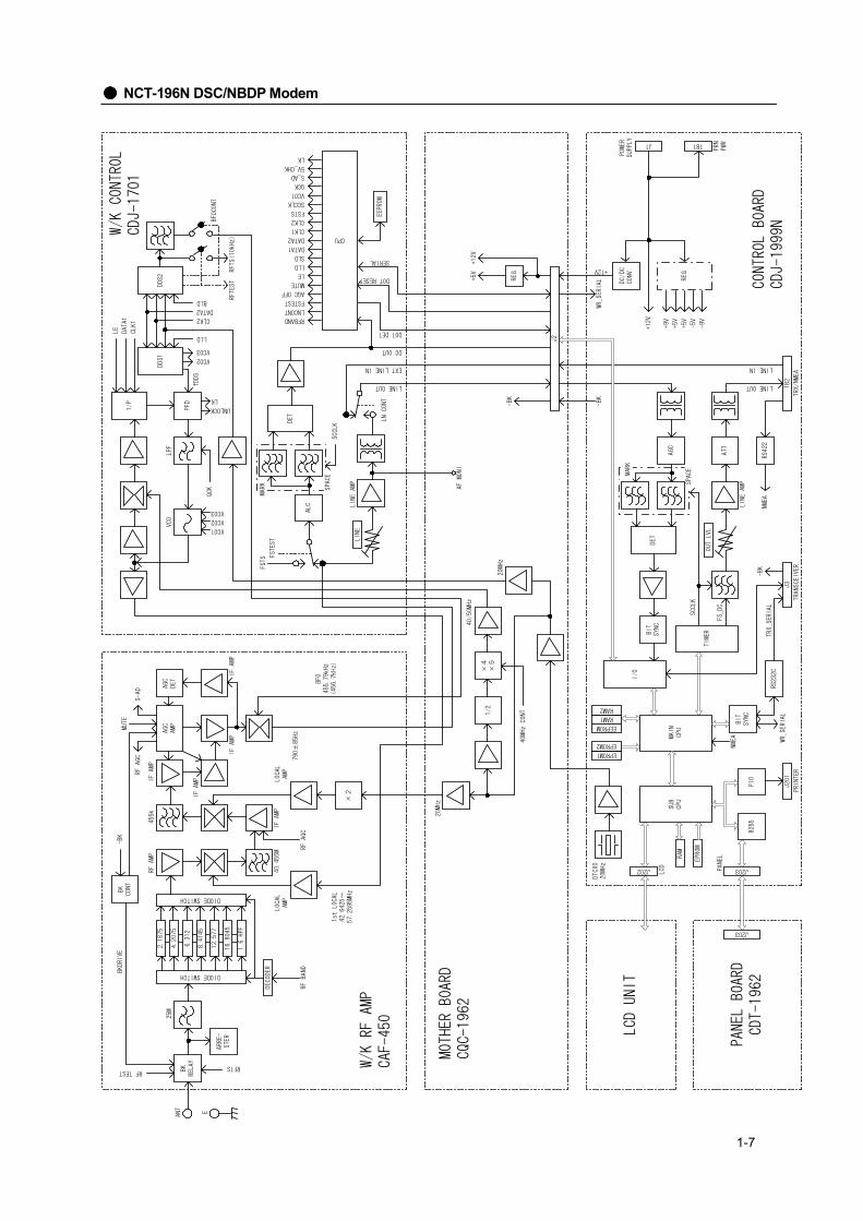
NCT-196N DSC/NBDP Modem

1-8
NAH-692 Power Amplifier
PFC
DC
24V
DC
/DC
1
DC
80V
DC
/DC
2D
C13
.6V
DC
/DC
4
AC IN
PA(A
)(3
00W
)
Split
er
Com
bine
rSu
rge
Supp
ress
orR
F O
UT
to A
TU
CO
NT
Seria
l(T
XD/R
XD)
Anal
og v
alue
PA_M
UTE
Seria
l(T
XD/R
XD)
PA_M
UTE
+BK/
-BK/
RBK
TX_I
NH
JSB-
196G
MR
adio
tele
phon
e
NFC
-196
ATU
Exte
rnal
Uni
ts
ANT
CU
RR
PA/P
S co
ntro
l
Anal
og v
alue
Alar
m
DC
24V(
Batte
ry)
DC
24V(
VHF)
DC
13.6
V(JS
B-19
6)
RF
INfro
m J
SB-1
96
DC80V
DC
26-3
0V
PS U
NIT
NA
H-2
96/5
96/8
96PA
UN
IT
PA U
NIT
*
Not
e)
JSS
-296
nee
ds P
A(A)
onl
y.
A
dditi
onal
ly J
SS-5
96 n
eeds
PA(
A) a
nd P
A(B)
, and
JS
S-89
6 ne
eds
all o
f the
PA
mod
ele
(A to
C).
DC
24V(
SES)
SES
orM
F/H
FD
C12
VSu
b-PS
DC
24V
DC
/DC
3
DC
350V
DC
12V
+BK/RBK
CONT
DC
24V
DC24V
DC24V
PA(B
)(3
00W
)
PA(C
)(3
00W
)
NAH
-692
/695
/698
PA
UNIT

1-9
NFC-296 Antenna Tuning Unit
RF
INPU
Tto
Ant
enna
L0L8
Ci0 C
i8
L9
Cp
Mat
chin
g se
nsor
CPU
PIO
Driv
er
I/F
Seria
lTX
D
SWR_VF
L_PHASE
SWR_VR
LOW_R (Impedance < 50 ohm)
Seria
lR
XD
Co0 C
o6
Cs
ANT
CU
RR
sens
or
UN
IT_A
Tem
pera
ture
dete
ctio
n
Res
et
E
+12V E
ANT_
CU
RR
9
9
7
30
A/D
A/D
JSB-
196G
MR
adio
tele
phon
e
Co_
on
HI_
TEM
P (in
side
> 7
0deg
)
TEM
P
PCB
ID U
NIT
_B
Dum
my
(50o
hm)
FRO
M
A/D
TRN
S
PA M
UTE

2-1
2. PART NAMES AND FUNCTIONS JSB-196GM Radio Equipment
Operation Panel
MIC Connector
Fuse 40A
Fuse 40A
Rx Antenna Input
Ground Terminal
Ground Terminal
External Speaker Output
ATU Control Output
Accessory Terminal
NCT-196N DSC/NBDP Modem
GLOBE E-mail (option) / PC
Telegraph Key Jack13.6VDC Power Source Input
PTT SwitchNQW-213Hand Set

2-2
Liquid Crystal Display Panel
MICConnects the hand microphone orhandset.
Turns power ON or OFF.
Controls the brightness of the LCD.
RF GAINControls the RF gain.
CLARIAdjusts the frequency variation, whichranges from –200 to +200Hz in 1Hzsteps.
,These buttons are used to inputfrequency/channel values or to set a menu.
Enters the input information.
Starts channel selection.
Jog DialUsed to select a channel or receivefrequency or to select a menu.
VOLUMEControls the sound volume of reception.
Turns the attenuator ON or OFF.
Starts antenna tuning.
Temporarily monitors the transmissionfrequency in the Semi-Duplex mode
Reduces pulsating noises.
POWER
DIMMER
NR
LISN/TX
ATT
CLRMENU90
ANTTUNE
CH
ENT
1 2 3 4 5A
, ., .
SCAN SQLRX FREQ
RDY TXTX FREQ
TUNE
ATT NRkHz AGC
kHz LO
MODE 2 1 8 2
COMPASS SAFE DISTANCE 1.5m

2-3
Operation Panel
DTE Terminal
Fuse 7.5A
13.6VDC Power Source Input
DMC Terminal
Ground Terminal
TRX/NMEA Terminal
JSB-196/196GM Terminal
Printer Terminal
Printer13.6VDC Power Output Terminal
Rx Antenna Input
Power Switch

2-4
① Liquid Crystal Display (LCD) Panel
② Sends a distress call.
③ Transmit/Receive lamp Red: Lights when a distress or emergency
call is being sent or received. Green : Lights when a normal call is being
sent or received.
④ ,Sets the JSB-196/196GM to the designatedfrequency and F1B mode.
⑤ ʽ Stops the call if pressed while a call is being sent.ʽ Turns off the alarm lamp and cancels the buzzer if
pressed when a call is being received.ʽ If you press this key followed by the , the
software version is displayed and the set navigationaid/radio equipment is momentarily displayed. (Thisis not the initial setting process.)
⑥ Press after editing a message to start
Transmission of the message.
⑦ to ,・ When editing, these keys enter the indicated
numbers.・ If you press the key followed by
to and , the following operations areperformed:
SCAN: Alternately starts and stops scanning when using the JSB-196/196GM to scan the receive frequencies.
DIM Adjusts the LCD and key brightness in four steps.
PRINT: Prints the current mode operations. In "DSC watching" mode, this key selects "PRINTMENU."
QUIT: Quits editing and returns to the higher mode (MENU, etc.).
POS: When selecting "WORK FREQUENCY" and "POSITION" when editing a message, this key switches to "POSITION".
FREQ: When selecting "WORK FREQUENCY" and "POSITION" when editing a message, this key switches to "WORK FREQUENCY".
SAVE: Saves edited data and returns to the higher mode (MENU, etc.).
⑧ Enters key input and selected items.
⑨ When pressed in "DSC watching" mode, the screen switches from "MENU#1" to "MENU#2" to "DSC watching", in that order.
⑩ Press this key to select the functions indicated in blue.
⑪ Horizontal: Use to selectively display received
messages and to select the contents when editing messages.
Vertical: Use to scroll the display and to move the screen pointer vertically.
⑫ ・ Deletes data that has been keyed in.・ Enters the initial value when entering "POSITION"
or "WORK FREQUENCY."
⑬ Watch-keeping receiver channel Lights the channel scanned by the watch- keeping receiver. 2187.5kHz and 8414.5kHz are fixed and cannot be switched.
5
DISTRESS
6
92187.5kHz 8414.5kHz
ENT
MENU
STOP
FUNC
FUNC
CALL
90 .
CLR
FUNC
96
1
2
3
4
NCT-196N DSC/NBDP MODEM

2-5
NAH-692 Power Amplifier

2-6
Liquid Crystal Display (LCD) PanelDisplay for menu mode or selected meter value
Menu Buttons・ DIM: Dimmer control switch (High/ Medium/ Low)・ CLR: Clear button for menu selection or alarm sound・ MENU: MENU mode setting button・ ENT: Selected menu or parameter entry button
Menu DialAdjust the LCD contrast and select the menu items
AC Power Switch
DC Power Switch
AC INAC100V 240V mains connector
DC13.6VDC13.6V power source output connector for JSB-196GM/NCT-196N
24V BATTERYDC24V power source input connector
ACCESSORYPeripherals (+/-BK, SES, ANT Changer, etc) control signal connector
TUNERTuning control signal connector (to NFC-296 ATU)
TUNER/JSB-196GMTuning control signal connector (from JSB-196GM Radiotelephone)
BATTERY MONITORBattery and charger status monitor output connector
AUX P/SDC24V power source output connector (for SES, VHF, etc)
PA INRF input connector (from JSB-196GM Radiotelephone)
PA OUTRF output connector (to NFC-296 ATU)
GND

2-7

3-1
3. OPERATIONS
This chapter describes mainly the way to use the JSS-296.
3.1 System Standby
3.1.1 Turning the Power ON
1. Turn on the AC and DC switches of NAH-692 Power Amplifier.The other components except for JSB-196GM Radiotelephone are turned ONsimultaneously. After that the LCD on the front panel of the NAH-692 Power Amplifiershows as follows.
AC Volt 221VDC Volt 24.2V
2. Turn on the POWER switch of JSB-196GM Radiotelephone. (Note that it isnecessary to keep the POWER switch press for 1 sec at least to turn it on.)
Keep the NCT-196N DSC/NBDP Modem power switch turn ON because of theobligation to watchkeep 24 hours a day while at sea.
3.1.2 Turning the Power OFF
1.1.1.1. Turn off the AC and DC switches of NAH-692 Power Amplifier.Turn off the AC and DC switches of NAH-692 Power Amplifier.Turn off the AC and DC switches of NAH-692 Power Amplifier.Turn off the AC and DC switches of NAH-692 Power Amplifier.
The other components including NCT-196N DSC/NBDP Modem are turnedOFF simultaneously. Therefore don’t turn OFF the switches while at seabecause of the obligation to watchkeep 24 hours a day.
Regarding the JSB-196GM Radiotelephone or NCT-196N DSC/NBDP Modem operations in detail,see the specialized instruction manuals for them respectively.
ATTENTION
Note
Note

3-2
3.2 MODEM MODE Change
After turning ON the system, according to the mode setting when the system was turned OFF last,the NCT-196N selects the mode. However if needed to change the mode, operate the system inaccordance with the following procedure.
3.2.1 MODE change to DSC
1. Confirm that the NCT-196N displays the following screen.
2. Press on the panel of the NCT-196N.
It is also available to press the keys concerning to Distress( , , or ) .
3. After the mode change completed, the following initial display appears.
The mode of the peripheral units such as JSB-196/196GM Radiotelephone and NDZ-127J DTE is changed to DSC mode simultaneously by the above-mentionedoperation.
DSC watching 06.Sep.2001(Thu) 01:26 12゚34’N123゚45’E SPEED:12.4KT at 01:26 Self-ID = XXXXXXXXX [UTC]
ENT
NoteDISTRESS2187.5kHz 8414.5kHz
DSC watching 06.Sep.2001(Thu) 01:26--------------------------------------------
MODE: XXXX (Press ENT to set DSC mode.)--------------------------------------------
Note

3-3
3.2.2 MODE change to TLX
1. Confirm that the NDZ-127J displays the following screen in any mode except for TLX.
2. Press Enter on the NDF-268 Keyboard.
3. After the mode change completed, the following initial display appears.
The mode of the peripheral units such as JSB-196/196GM and NCT-196N is changedto TLX mode simultaneously by the above-mentioned operation.
Note
↑ ↓ → ←
↑ ↓ → ←

3-4
3.3 Setting Position and Time Data
3.3.1 Setting the Internal Clock(DATE & TIME EDIT)
The built-in clock of the NCT-196N can be set the date (year, month, and day) and time manually. However if theNCT-196N is connected to a navigation aid, the manual input data is overwritten because the navigation aid haspriority over the NCT-196N internal clock. The standard time is UTC but it is possible to input time difference fromthe UTC and display the current local time (LT). Note that in case of no navigation aid connecting, time data shouldbe set to the present time manually and periodically because the time data input manually is treated as invalid dataand deleted after 23.5 hours past.
Procedure
1. Check that the "DSC watching" screen is displayed.
If the "DSC watching" screen is not displayed, press 3 times in succession to switch to the"DSC watching" screen.On the screen mark is displayed when no printer is connected to the NCT-196N.
2. Press .The "MENU#1-EDIT&CALL" screen is displayed.
STOP
MENU
DSC watching 06.Sep.2001(Thu) 01:26 P 12゚34’N123゚45’E SPEED:12.4KT at 01:26 Self-ID = XXXXXXXXX [UTC]
MENU #1-EDIT&CALL Select no. 1.Individual call 2.Acknowledgement call 3.Distress call
4.Distress relay call 5.Auto/semi-auto call 6.All ships call Use and to scroll. 7.Group call 8.Area call 9.Position request 10.Polling call 11.Test call
▼▲
P
Note
If the position and time data from navigation aids such as a GPS receiver stop for more than 5 minutes,or if it past for more than 4 hours without further input after entering position and time data manually, theNCT-196N sounds alarm. When the alarm sounding in condition of navigation aid connecting, checkthe navigation aid or the connections to the NCT-196N. Or when the alarm sounding in condition of nonavigation aid connecting, enter the new position and time data manually.
ATTENTION

3-5
Use and to scroll.
3. Press again.The "MENU#2-READOUT&SETUP" screen is displayed.
4. Press , and then press .The "SETUP" screen is displayed.
5. From the "SETUP" screen, press , and then press .The "DATE&TIME EDIT" screen is displayed.
6. Enter the respective settings.
When the display time is set to "LT", enter the difference to the UTC in the "Time difference" item.Use the cursor keys ( and ) to switch between "+/-" for the "Time difference" and between"UTC/LT" for the "Display time".
7. On completion of entering the data, press , and then press (SAVE).Operation returns to the "SETUP" screen.
If you press , and then press (QUIT), the settings are discarded.
1 ENT
DATE&TIME EDIT Date (dd:mm:yy):06.05.00 Time (hh:mm) :19:23 Time difference:-05:00
Display time :UTC Use and to scroll.▲ ▼
9FUNC
FUNC 4
MENU
3 ENT
SETUP Select no. 1.Date&time edit 2.Position edit 3.Calling frequency registration
4.Address registration 5.Distress setup Use and to scroll. 6.Others alarm setup 7.Automatic acknowledgement setup 8.Scanning setup 9.Watchkeeping receiver setup
▲ ▼
MENU #2 -READOUT&SETUP Select no. 1.Received distress message readout 2.Received others message readout 3.Setup
4.Self test ▲ ▼
Note
3-6
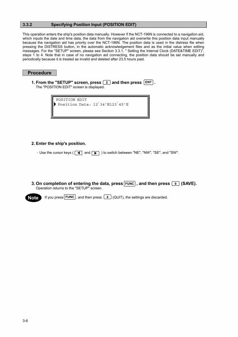
3.3.2 Specifying Position Input (POSITION EDIT)
This operation enters the ship's position data manually. However if the NCT-196N is connected to a navigation aid,which inputs the date and time data, the data from the navigation aid overwrite this position data input manuallybecause the navigation aid has priority over the NCT-196N. The position data is used in the distress file whenpressing the DISTRESS button, in the automatic acknowledgement files and as the initial value when editingmessages. For the "SETUP" screen, please see Section 3.3.1, " Setting the Internal Clock (DATE&TIME EDIT)",steps 1 to 4. Note that in case of no navigation aid connecting, the position data should be set manually andperiodically because it is treated as invalid and deleted after 23.5 hours past.
Procedure
1. From the "SETUP" screen, press and then press .The "POSITION EDIT" screen is displayed.
2. Enter the ship's position.
Use the cursor keys ( and ) to switch between "NE", "NW", "SE", and "SW".
3. On completion of entering the data, press , and then press (SAVE).Operation returns to the "SETUP" screen.
If you press , and then press (QUIT), the settings are discarded.
ENT
POSITION EDIT Position Data: 12゚34’N123゚45’E
9FUNC
FUNC 4
2
Note

3-7
3.4 Radiotelephone operations3.4.1 Turning the Power ON / OFF
CAUTIONNever touch the antenna terminal, grounding terminal or counterpoise when theJSB-196GM is turned ON. Doing so, may cause electrical shock.
Place Antenna Tuner NFC-196, antenna and counterpoise in position where no onetouches them. Doing not so, may cause electrical shock.
3.4.1.1 Turning the Power ON
Press on the front panel until the channel and frequencies are displayed as follows:
Figure 5.1 Initial display on the LCD (immediately after the equipment is powered on)
3.4.1.2 Turning the Power OFF
Press until LCD disappears.
The latest frequency and set-up state information such as communication mode arestored in memory when the equipment is turned OFF. It will be set automatically whenthe equipment is powered on again except the following items and these items will beset to as follows:
⋅ Built-in loudspeaker ON/OFF (ON as default)⋅ Squelch value (0 as default)
POWER
POWER
Note
RX FREQ ,,,, .... KHz
TX FREQ ,,,, .... KHz
NRAGC
RDY

3-8
3.4.2 Communication Procedure
The JSB-196GM employs the Jog Dial for simply setting or selection for principal functions such asTX/RX frequency, communication mode, output power, squelch, AGC, etc. and the followingprocedures are provided for pleasant communication.
3.4.2.1 Setting the channel number with the Jog Dial
User channels can be set with the Jog Dial.
Procedure Examples of display on the LCD
Example of user channel number 101
1. Press .
Group number appears in the channel fieldof the LCD.
(in the TEL mode)
2. Turn the Jog Dial. (*1)
Turn the Jog Dial until the group number,ex. ”GROUP 6 TEL”, including the objectivechannel number is displayed.
3. Press .
User channel number is displayed.
4. Turn the Jog Dial again until the objectivenumber, ”USR-101” is displayed andcomplete setting.
If is blinking, press .
lights steadily during tuning, anddisappear when tuning is completed.
5. With these steps, the JSB-196GM is readyto communicate. Start communication bypressing PTT on the hand set.
*1 For easy selection of a channel number, you can allocate an identification label to each channel (See "5.3.6 Registering a user channel").
CH
Note
ANTTUNE
RX FREQ KHz
TX FREQ KHz
TUNE
NB
AGC
RDY
,,,, ....,,,, ....RDY
RX FREQ KHz
TX FREQ KHz
TUNE
NRAGC
RDY
,,,, ....,,,, ....
TUNE
TUNE
ENT

3-9
3.4.2.2 Monitoring the transmission frequency
In semi-duplex mode the TX/RX frequency are set differently , though only one way transmission orreception is possible at the same time. The transmission frequency signal can be checked forinterference.
Procedure
1. Press .
JSB-196 starts to receive TX frequency. After the check, press again or transmit to return to the initial state.
3.4.2.3 Setting the channel number with keypad
User channel number can be set with keypad as follows.
Procedure Examples of display on the LCD
Example of user channel number 101 (RXfrequency 26145.0 kHz / TX frequency25070.0 kHz).
1. Press .
"GROUP 1 TEL" appears in the channelfield of the LCD.
(in the TEL mode)
2. Press , and .
The channel number is displayed in thechannel field of the LCD.
User channel number: 1 to 200ITU channel number: TEL: 401 to 2517 CW : 401 to 2524
TLX: 401 to 2571 DSC: 401 to 2503
3. Press .
The input channel number is fixed.
4. Input the RX/TX frequency.
See the「4.3.3.6 Registering the user channelstep 4~7」.
5. If is blinking, press .
lights steadily during tuning, anddisappear when tuning is completed.
6. With these steps, the JSB-196GM is readyto communicate. Start communication bypressing PTT on the Hand set.
At channel setting, current mode must not be DSC mode.
CH
0 1
ENT
ANTTUNETUNE
TUNE
RX FREQ KHz
TX FREQ KHz
TUNE
NB
AGC
RDY
,,,, ....,,,, ....RDY
RX FREQ KHz
TX FREQ KHz
TUNE
NRAGC
RDY
,,,, ....,,,, ....
LISN/TX
LISN/TX
1
Note
Note

3-10
3.4.2.4 Manually inputting frequency
In this case, communication mode must be set in advance(For setting of a radio mode, see "5.3.1setting a communication mode").TX and RX frequency can be set with keypad as follows.
Procedure Examples of display on the LCD
Example of RX frequency 4357.0 kHz / TXfrequency 4065.0 kHz .
1. Press , , , and forthe RX frequency. The RX frequency isdisplayed in the channel field of the LCD.
2. Press .
The RX frequency is fixed. When you wantto use this frequency also as a TXfrequency, press again.
(in the TEL mode)
3. Press , , , and forthe TX frequency. The TX frequency isdisplayed in the channel field of the LCD.
4. Press .
The TX frequency is fixed.
5. If r is blinking, press .
lights steadily during tuning, anddisappear when tuning is complete.
6. With these steps, the JSB-196GM is readyto communicate. Start communication bypressing PTT on the Hand set.
• Press two or three times , enable to change the RX/TX frequency individually.
• Press to change the DISTRESS frequency 2,182.0 kHz.
4 3 5 7 0
4 0 6 5 0
ENT
ANTTUNETUNE
TUNE
ENT
RX FREQ KHz
TX FREQ KHz
NRAGC
RDY
RX FREQ KHz
TX FREQ KHz
NRAGC ,,,, ....
,,,, ....RDY
RX FREQ KHz
TX FREQ KHz
NBAGC
TUNE
,,,, .... ,,,, ....RDY
RX FREQ KHz
TX FREQ KHz
RDY TUNE
NRAGC ,,,, ....
,,,, ....
ENT
CHNote
0

3-11
3.4.2.5 Scanning reception
The reception frequency stored in user channel group 1 to 10, each 20 channels can be scanned.You can select a desired group (20 user channels per group) for scanning.
Procedure Examples of display on the LCD
Example of group 7.
1. Press , then turn the Jog Dial until"SCAN" appears in the channel field of theLCD.
(in the TEL mode)
2. Press .
"Group 1 1" appears in the channel field ofthe LCD.
3. Turn the Jog Dial until objective group isdisplayed.
4. Press .
Scanning reception starts.
appears on the center left of the LCD.The group name and number which arescanned are displayed in the channel field ofthe LCD.
5. To cancel scanning, press . The lastcommunication mode and the frequenciesare set.
RX FREQ KHz
TX FREQ KHz
SCAN NRAGC
RDY TUNE,,,, ....,,,, ....
ENT
MENU
ENT
SCAN
CLR

3-12
3.4.3 Other Function Settings
The function setting is basically executed by using key and the Jog Dial, and the settableitems blinks and is set with key.
3.4.3.1 Setting the communication mode
In the use of manually inputting frequency, communication mode must be set in advance.
Procedure Examples of display on the LCD
Example of CW.
1. Press .
"MODE" in the channel field of the LCDblinks.
(in the TEL mode)
2. Press .
The current communication mode "TEL"blinks.
3. Turn the Jog Dial.
Turn the Jog Dial until objective mode."CW" is blinking.
4. Press .
CW is fixed as communication mode.
5. If is blinking, press .
lights steadily during tuning. Anddisappear when tuning is complete.
• Press to change the communication mode successively.
MENU
ENT
MENU
ENT
ANTTUNETUNE
TUNE
ENT
RX FREQ KHz
TX FREQ KHz
NBAGC
TUNE
,,,, ....,,,, ....RDY
RX FREQ KHz
TX FREQ KHz
NRAGC
RDY TUNE,,,, ....,,,, ....
Note CLR

3-13
3.4.3.2 Setting the output power
The output power can be set to "HI (150W)" or "LOW (50W)".
Procedure Examples of display on the LCD
1. Press ,then turn the Jog Dial until"Power" in the channel field of the LCDblinks.
2. Press .
The current out power "HI" blinks.
3. Turn the Jog Dial until "LOW " blinks.
4. Press .
The output power is set to "LOW ". on the lower right corner of the LCDturns on.
3.4.3.3 Turning the Automatic Gain Control (AGC) ON
The AGC circuit functions to maintain a constant receiver output by automatically adjusting the gainaccording to the strength of the reception signals.
Procedure Examples of display on the LCD
1. Press , then turn the Jog Dial until"AGC" in the channel field blinks.
2. Press .
The current AGC status "SLW" blinks.
3. Turn the Jog Dial until desirable state "FST"or "OFF" appears.
4. Press .
The desirable "AGC" state is fixed.
“AGC” turn on the right corner of the LCDwhen you set to "SLW" or "FST".
In “TLX” mode, “AGC” state is fixed to “FST”. (You can not set to “SLW”.)
MENU
ENT
ENT
LO
MENU
ENT
ENT
Note

3-14
3.4.3.4 Adjusting squelch level
The squelch circuit functions to mute received signals based on its level. The larger the squelch level,the larger the antenna input level is required to open the squelch circuit. When the squelch circuit isactivated (mute status), in the LCD turns on.
Procedure Examples of display on the LCD
1. Press ,then turn the Jog Dial until"SQUELCH" blinks.
2. Press .
The current squelch level “0” blinks.
3. Turn the Jog Dial until desired squelch levelappears. When turn the Jog Dial, the bar onthe bottom of the LCD expands to indicatethe squelch level.
4. Press .
The squelch level is fixed.
MENU
ENT
RX FREQ ,,,, .... KHz
TX FREQ ,,,, .... KHz
SQL NRAGC
RDY TUNE
SQL
ENT

3-15
3.4.3.5 Setting the scanning speed
The scanning time for each channel is settable between 0.3 to 5 seconds.(multiple of 0.1 second)
Procedure Examples of display on the LCD
Example of 0.3 seconds.
1. Press , then turn the Jog Dial until"SCAN SPD" blinks.
2. Press .
The current value “10” blinks.
3. Turn the Jog Dial until desirable scanningtime appears or manually input the valuefrom keypad.
4. Press .
The scanning time is fixed to 0.3 seconds.
3.4.3.6 Registering the user channel
You use frequently can be registered as a user channel up to 200, channel number 1 to 200.
Procedure Examples of display on the LCD
Example of registration for RX frequency 4357.0kHz / TX frequency 4065.0 kHz, communicationmode is TEL, Channel Label Registration isMITAKA1 at the user channel number 1.
1. Make sure that a objective communicationmode is set and press and thenturn the Jog Dial until "USR MEMO" blinks.
2. Press .
Select the user channel number with the JogDial or keypad.
3. Press .
Select the communication mode with the JogDial(*1).
MENU
ENT
ENT
MENU
ENT
ENT

3-16
Procedure Examples of display on the LCD
4. Press .
Press , , , and forthe RX frequency. The RX frequency isdisplayed in the channel field of the LCD.
5. Press .
The RX frequency is fixed(*2).
6. Press , , , and forthe TX frequency. The TX frequency isdisplayed in the channel field of the LCD.
7. Press .
The TX frequency is fixed.
8. Select an alphabet or number(MITAKA1)with the Jog Dial. Input decision or “SPACE”key is .
After selection, press , and fix to press (*3).
9. The Channel Label Registration mode isset. If you want to complete the inputtinguser channel, two times .
*1 When correct the registered channel, press , then select the collection itemas follows:
In case of change the communication mode or clear the channel, turn the Jog Dial.Then press .
In case of change the RX or TX frequency or the channel Label,press successively and input the new parameter.
*2 In step 2, the frequency can be inputted manually. RX frequency and a TXfrequency in this order and go to step 8 (When you want to use an identicalfrequency for reception and transmission, press only after inputting RXfrequency).
*3 In step 7, you do not need the label, press and go to step 9.
Note
ENT
ENT
ENTCLR
ENT
ENT
CLR
ENT
4 3 5 7 0
ENT
4 0 6 5 0
CH
RX FREQ KHz
TX FREQ KHz
NRAGC ,,,, ....
,,,, ....RDY
RX FREQ KHz
TX FREQ KHz
NBAGC
TUNE
,,,, .... ,,,, ....RDY
RX FREQ KHz
TX FREQ KHz
NBAGC
TUNE
,,,, .... ,,,, ....RDY
ENT
ENT

3-17
3.4.3.7 Registering a channel group name
200 user channels are grouped into 10 groups, each 20 channels. These groups are used forscanning reception, and can be named for quick selection.
Procedure Examples of display on the LCD
1. Press , then turn the Jog Dial until"GRP MEMO" blinks.
2. Press .
A group number “1” blinks in the right end ofthe channel field of the LCD.
3. Turn the Jog Dial until the objective groupappears.
4. Press .
“_” blinks.
5. Repeat to select an alphabet or numberwith the Jog Dial, and press eighttimes.
6. Channel group number is fixed.
MENU
ENT
ENT
ENT

3-18
3.4.3.8 Setting the meter indication mode
The bar indicator on the bottom of the LCD indicates signal level during reception or output duringtransmission, furthermore output indication is settable to the output power mode or antenna currentmode.
Procedure Examples of display on the LCD
1. Press , then turn the Jog Dial until"METER" blinks .
2. Press .
"PWR" blinks.
3. Turn the Jog Dial until desired modeappears.
"PWR" : Indication for output power.
"ANT" : Indication for antenna current.
4. Press .
Indication mode, "PWR" or "ANT", is fixed.
3.4.3.9 Setting the Automatic Tuning Start (ATS)
The ATS function is used for pre-tuning at change of channel / frequency, and tuning startsautomatically when the standing-wave ratio (SWR) is wrong.
Procedure Examples of display on the LCD
1. Press , then turn the Jog Dial until"ATS" blinks.
2. Press .
"OFF" blinks.
3. Turn the Jog Dial to set "ON" or "OFF".
4. Press .
The ATS function is turned "ON" or "OFF" .
MENU
ENT
ENT
MENU
ENT
ENT

3-19
3.4.3.10 Setting the wait time for ATS
On the ATS function, wait time for tuning start after change of channel / frequency is adjustable.
Procedure Examples of display on the LCD
1. Press , then turn the Jog Dial until"ATS WAIT" blinks.
2. Press .
"3" blinks.
3. Turn the Jog Dial to select the time ormanually input the time with keypad.
4. Press .
The wait time is fixed.
3.4.3.11 Turning the key-in sounds ON / OFF
The key-in sounds are available for keypad operation.
Procedure Examples of display on the LCD
1. Press , then turn the Jog Dial until"BEEP" blinks.
2. Press .
“BEEP” lights steadily and "ON" blinks.
3. Turn the Jog Dial to select "ON" or "OFF".
4. Press .
The key-in sounds are turned "ON" or"OFF".
The key-in sounds are suspended, when set the loudspeaker OFF.
MENU
ENT
ENT
ENT
ENT
MENU
Note

3-20
3.4.3.12 Setting the loudspeaker output ON / OFF
The loudspeaker output can be turned OFF.
Procedure Examples of display on the LCD
1. Press , then turn the Jog Dial until"SPEAKER" blinks.
2. Press .
"SPEAKER" lights steadily and "ON" blinks.
3. Turn the Jog Dial to select "ON" or "OFF".
4. Press .
The loudspeaker output is turned "ON" or"OFF".
MENU
ENT
ENT

3-21
3.4.3.13 List of shortcut keys
The following shortcut keys are provided for easy selection of menu items.
Using a shortcut key: The expression "1. Press , then turn the Jog Dial" in the aboveprocedure steps can be substituted by " Press and input its shortcut key number withkeypad".
Menu item Shortcut keynumber Function
MODE 1 Select the communication mode.
TEL (J3E), DSC (F1B), TLX (F1B), CW (A1A), AME (H3E)
POWER 2 Set the output power to low (50 watts).
AGC 3 Select the AGC (Auto Gain Control) function.
SQUELCH 4 Adjust the squelch level.
SCAN 5 Enable the scanning function.
SCAN SPD 6 Set the scanning time.
USR MEMO 7 Register the user channel.
GRP MEMO 8 Register the channel group name.
METER 9 Select the bar-meter function.
ANT: antenna current, PWR: output power.
ATS 10 Enable the ATS (Automatic Tuning Start) function.
ATS WAIT 11 Set the wait time for the ATS function.
BEEP 12 Disable the key-in sound panel.
SPEAKER 13 Disable the output of the built-in loudspeaker.
CHECK 14 Perform the Self Diagnosis function.
VERSION 15 Display the farm-ware version on Control unit CDJ-1960, DSP,Antenna Tuner and Power Amplifier.
In JSS-296, Control unit’s version must be 2.00 or later.
MENUMENU
Note

3-22

3-23
3.5 DSC operationsThis section describes menus and modes (Section 3.5.1), receiving DSC calls (Section 3.5.2), and making DSCcalls (Section 3.5.3). Section 3.5.4 describes how to store the calling frequencies used with the DSC, and thesetting of destination IDs, etc.
3.5.1 Menus and Modes
(1) Menu HierarchyThe menus displayed on the screen have the following hierarchical structure.
DSC watching
MENU#1-EDIT&CALL1.Individual call2.Acknowledgement call3.Distress call4.Distress relay call5.Auto/semi-auto call6.All ships call7.Group call8.Area call9.Position request
10.Polling call 11.Test call
MENU#2-READOUT&SETUP1.Received distress message readout2.Received others message readout3.Setup
1.Data&time edit2.Position edit3.Calling frequency registration4.Address registration5.Distress setup6.Others alarm setup7.Automatic acknowledgement setup8.Scanning setup9.Watchkeeping receiver setup
4.Self test1.Modem loop test2.Printer test3.Display test4.Frequency remote test5.Watchkeeping receiver test
RECEIVED MESSAGE
PRINT MENU1.ALL RECEIVED DISTRESS MESSAGES2.ALL RECEIVED OTHERS MESSAGES3.ALL EDIT/CALL MESSAGES4.ALL SETUP INFORMATION

3-24
(2) Transition Among ModesThe following chart shows the keys and key combinations used to shift from one mode to anotheron the NCT-196N.
Select print menu.
Quit print menu.
Received message
Press once to clear the call alarmand call lamp.
Press once more to quit callmessage display mode.
No. selection
Discards the current edits and quitsediting.
Saves the current edits and quitsediting.
or Quits readout of received message.
No. selection
No. selection
No. selection
Discards the current settings andquits editing.
Saves the current settings andquits editing.
Stops self-diagnostic tests.
Quits self-diagnostic mode.
(From any mode, press three times to return to "DSC watching.")
DSCwatching
Display and printreceived message.
MENU #1
MENU #2
Printmenu
Messageediting
Selfdiagnosis
Varioussettings
Readoutreceived
message.
4FUNC
FUNC 3
STOP
STOP
4FUNC
9FUNC
MENU
MENU
MENU
4FUNC
4FUNCSTOP
4FUNC
9FUNC
STOP
9FUNC
FUNC
STOP
4

3-25
3.5.2 Receiving Messages
(1) Receiving a MessageWhen a message is received, it is displayed on the screen and printed out on the printer, if a printer is connected.In addition, depending on its content, the message is classified as either a distress/urgent message or a generalmessage and the corresponding panel lamp blinks. Simultaneously, a buzzer sounds to indicate which type ofmessage has been received. The message is then saved as either a distress/urgent message or a generalmessage.
The NCT-196N stores up to 20 received distress/urgent messages and up to 20 general messages. When 20messages have been stored, the oldest message is deleted each time a new message is received.
In case of distress/urgent messages, newly received messages are not stored if a message with the same contentalready exists in memory. However, if any error occurs while receiving the message, both of the messagescontaining the error and the error-free message are stored.In case of general messages, the NCT-196N stores both the original message and the new message even if theyhave the same content as each other.
Distress/urgent messages ・・・・・Messages in "DISTRESS" format or for which the category is"DISTRESS" or "URGENCY".
General messages ・・・・・・・・・・・Messages other than distress/urgent messages.
Print receivedmessage.
Is this a distress orurgent message?
DISTRESS/URGENCY lamp lights.Distress/urgent buzzer sounds.Message stored internally as distress/urgentmessage.Note, however, that if a message with identicalcontent has already been received, thismessage is not stored.
OTHERS lamp lights.General call buzzer sounds.Message stored internally as general message.Note that even if a message with identicalcontent has already been received, thismessage is stored.
YESYESYESYES
NONONONO
Note

3-26
Use and to scroll.
(2) Reading a Distress/Urgent MessageMessages are loaded at the "DSC watching" screen.
ATTENTION To prevent unnecessary distress message relay transmission, the NCT-196N automatically deletes distress/urgency messages after 48 hours since these received. Thus the procedure above- mentioned to read distress message received is invalid at that time.
Procedure
1. Check that the "DSC watching" screen is displayed.
If the "DSC watching" screen is not displayed, press 3 times in succession to switch to the"DSC watching" screen.On the screen mark is displayed when no printer is connected to the NCT-196N.
2. Press .The "MENU#1-EDIT&CALL" screen is displayed.
3. Press again.The "MENU#2-READOUT&SETUP" screen is displayed.
STOP
MENU
MENU
DSC watching 06.Sep.2001(Thu) 01:26 P 12゚34’N123゚45’E SPEED:12.4KT at 01:26 Self-ID = XXXXXXXXX [UTC]
MENU #1-EDIT&CALL Select no. 1.Individual call 2.Acknowledgement call 3.Distress call
4.Distress relay call 5.Auto/semi-auto call 6.All ships call Use and to scroll. 7.Group call 8.Area call 9.Position request 10.Polling call 11.Test call
▼▲
MENU #2 -READOUT&SETUP Select no. 1.Received distress message readout 2.Received others message readout 3.Setup
4.Self test▲ ▼
PNote

3-27
RECEIVED DISTRESS MESSAGE READOUT #01 RX date&time :06.Sep.2001(Thu) 01:26 Format :DISTRESS Address :XXXXXXXXX
Nature :UNDESIGNATED DIST Dist-position :12 ゚ 34’N123 ゚ 45’E Dist-UTC :01:26 Dist-telecomm :J3E TEL End of sequence:EOS RX frequency : . kHz
Use and to scroll.
4. Press , and then press .The "RECEIVED DISTRESS MESSAGE READOUT" screen is displayed.
Use the horizontal cursor keys ( and ) to display other received messages.
The following screen is displayed if no distress messages have been received or deleted after48hours past.
5. After reading the message(s), press , and then press .Operation returns to the "MENU#2 READOUT&SETUP" screen.
6. Press .Operation returns to the "DSC watching" screen.
1 ENT
▲ ▼
RECEIVED DISTRESS MESSAGE READOUT
Received message not found !!
MENU
FUNC 4
Note
3-28
Use and to scroll.
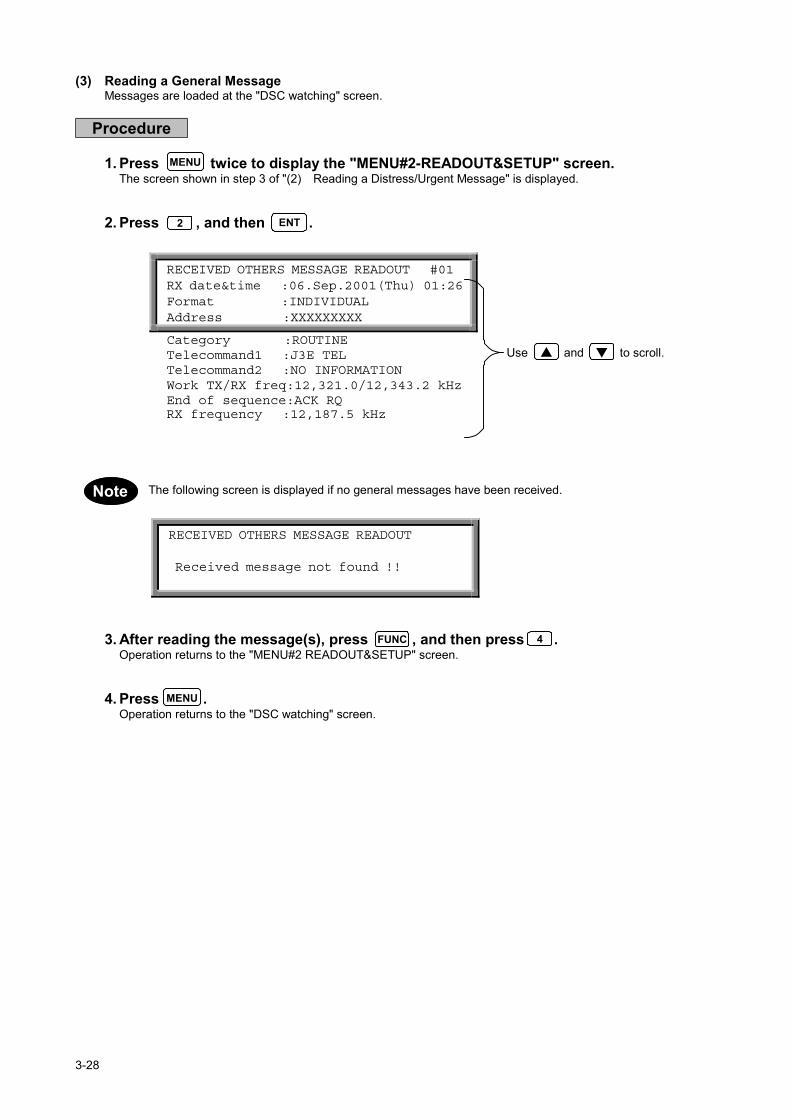
(3) Reading a General MessageMessages are loaded at the "DSC watching" screen.
Procedure
1. Press twice to display the "MENU#2-READOUT&SETUP" screen.The screen shown in step 3 of "(2) Reading a Distress/Urgent Message" is displayed.
2. Press , and then .
The following screen is displayed if no general messages have been received.
3. After reading the message(s), press , and then press .Operation returns to the "MENU#2 READOUT&SETUP" screen.
4. Press .Operation returns to the "DSC watching" screen.
MENU
2 ENT
RECEIVED OTHERS MESSAGE READOUT #01 RX date&time :06.Sep.2001(Thu) 01:26 Format :INDIVIDUAL Address :XXXXXXXXX
Category :ROUTINE Telecommand1 :J3E TEL Telecommand2 :NO INFORMATION Work TX/RX freq:12,321.0/12,343.2 kHz End of sequence:ACK RQ RX frequency :12,187.5 kHz
RECEIVED OTHERS MESSAGE READOUT
Received message not found !!
MENU
FUNC 4
▲ ▼
Note

3-29
3.5.3 Sending Messages
The following table lists the menus and menu items. When compiling a message, select the necessary items fromthese menus. Refer to the section on making calls for how to select the items for the respective call types.
Menu Menu items ContentFORMAT INDIVIDUAL
AUTO/SEMI-AUTODISTRESSALL SHIPSGROUPAREA
CATEGORY URGENCYSAFETYSHIP’S BUSINESSROUTINEDISTRESS
TELECOMMAND1 POLLINGUNCOMPLYDATA MODEMJ3E TELF1B/J2B FEC TTYF1B/J2B ARQ TTYF1B/J2B REC TTYF1B/J2B TTYA1A MORSE RECORDSHIP’S POSITIONA1A MORSE KEYF1C/F2C/F3C FAXNO INFORMATIONF3E/G3E SIMP TELF3E/G3E DUP TELDISTRESS RELAYDISTRESS ACKEND OF SEQUENCETEST
TELECOMMAND2 NO INFORMATIONRES18SHIP/AIRMEDICAL TRANSPUB CALL OFFICENO REASONCONGESTIONBUSYQUEUESTATION BARREDNO OPERATORNO OPR TEMPRYEQUIP DISABLEDUNUSABLE FREQUNUSABLE MODEITU-T V.21ITU-T V.22ITU-T V.22 BISITU-T V.23ITU-T V.26 BISITU-T V.26 TERITU-T V.27 TERITU-T V.32

3-30
Menu Menu items ContentNATURE UNDESIGNATED DIST
ABANDONINGEPIRB EMISSIONFIRE EXPLOSIONFLOODINGCOLLISIONGROUNDINGLISTINGSINKINGDISABLED ADRIFTMAN OVERBOARDPIRACY ROBBERY
TELECOMMAND J3E TELF3E J3E SIMP TELF3E J3E DUP TELF1B J2B FEC TTYF1B J2B ARQ TTY
EOS ACK RQACK BQEOS
3-31
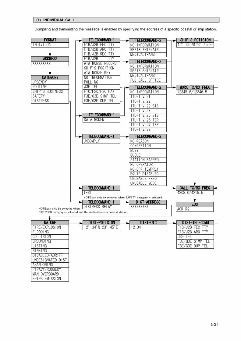
(1) INDIVIDUAL CALL
Compiling and transmitting the message is enabled by specifying the address of a specific coastal or ship station.
NOTE:can only be selected when SAFETY category is selected.
NOTE:can only be selected whenDISTRESS category is selected and the destination is a coastal station.

3-32
INDIVIDUAL CALL Transmissible Address :XXXXXXXXX Category :ROUTINE Telecommand-1 :J3E TEL
Telecommand-2 :NO INFORMATION Ship’s position:12 ゚ 34’N123 ゚ 45’E Call TX/RX freq: 4,208.0/ 4,219.5 kHz
Use and toscroll the screen.
Procedure
Example: ROUTINE procedure.
1. Check that the "DSC watching" screen is displayed.
2. Press .The "MENU#1-EDIT&CALL" screen is displayed.
3. Press , and then press .The "INDIVIDUAL CALL" screen is displayed.
The following items have been set in this example.Address XXXXXXXXXCategory ROUTINETelecommand-1 J3E TELTelecommand-2 NO INFORMATIONShip’s position :12 ゚ 34’N123 ゚ 45’ECall TX/RX freq :4,208.0/4,219.5 kHz
MENU
1 ENT
▲ ▼
DSC watching 06.Sep.2001(Thu) 01:26 12゚34’N123゚45’E SPEED:12.4KT at 01:26 Self-ID = XXXXXXXXX [UTC]
MENU #1-EDIT&CALL Select no. 1.Individual call 2.Acknowledgement 3.Distress call
4.Distress relay call 5.Auto/semi-auto call 6.All ships call Use and to scroll the screen. 7.Group call 8.Area call 9.Position request 10.Polling call 11.Test call
▼▲

3-33
●Entering the respective items:
After selecting each item, press to confirm the selection.(1) Address: Use the numerical keys ( to ) to specify the address of the destination
station (coastal or ship station).(2) Category
Telecommand-1: Use the and keys to select the items.Telecommand-2
(3) Ship's position: Use the and keys to determine the direction, and then input theship's position using the numerical keys ( to ).
(4) Call TX/RX freq: Use the and keys to select one of the preset frequencies, or usethe numerical keys ( to ,and ) to specify a frequency directly.
(5) Other settings:"Work TX/RX freq": Use the numerical keys ( to ,and ) to specify a frequency
directly.
Switching from "Ship's position" to "Work TX/RX freq": Press (FREQ).
Switching from "Work TX/RX freq" to "Ship's position": Press (POS).
Set the "Work TX/RX freq" to a frequency in the same band as "Call TX/RX freq".
4. Press .The following screen is displayed and the message is transmitted.
When the transmission is completed, the following screen is displayed for a while, and the message issaved. After that returns to the "MENU#1-EDIT&CALL" screen.
Refer to the example in "(6) ALL SHIPS CALL" for information on the DISTRESS RELAY procedure.To store a message without sending it, press (SAVE).To discard the message and quit, press (QUIT).
0 9
0 9
0 9 .
FUNC 6
FUNC 5
ENT
CALL
INDIVIDUAL CALL Transmitting TX frequency : 4,208.0 kHz TX date&time : 06.Sep.2001(Thu) 01:30
INDIVIDUAL CALL Send Completed TX frequency : 4,208.0 kHz TX date&time : 06.Sep.2001(Thu) 01:30
FUNC9FUNC
4
0 9 .
Note
Note

3-34
(2) ACKNOWLEDGEMENT CALL
In the event that the received general message requests acknowledgement, a message of acknowledgement isautomatically produced. Creating and transmitting a distress acknowledgement message is also possible.

3-35
Use and toscroll the screen.
(2-1) INDIVIDUAL ACK CALL
Procedure
Example: An acknowledgement call based on the message received
1. From the "MENU#1-EDIT&CALL" screen, press , and then press .The "Acknowledgement" screen is displayed.
1 :Select 1 to edit the received message.2, 3 :Select 2 or 3 to edit a new acknowledgement message.
2. Press , and then press .The "INDIVIDUAL ACK CALL" screen is displayed.
The following items have been set in this example.
Address :XXXXXXXXXCategory ROUTINETelecommand-1 J3E TELTelecommand-2 :NO INFORMATIONWork TX/RX freq :12,345.6/12,456.7 kHzCall TX/RX freq :4,357.0/4,388.5 kHz
●Entering the respective items:
After selecting each item, press to confirm the selection.(1) Address: Use the numerical keys ( to ) to specify the address of the destination station
(coastal or ship station).(2) Category
Telecommand-1: Use the and keys to select the items.Telecommand-2
(3) Work TX/RX freq: Use the numerical keys ( to , and ) to directly specify afrequency.
(4) Call TX/RX freq: Use the and keys to select one of the preset frequencies, or usethe numerical keys ( to ,and ) to specify a frequency directly.
(5) Other settings:・Switching from "Ship's position" to "Work TX/RX freq": Press (FREQ).
・Switching from "Work TX/RX freq" to "Ship's position": Press (POS).
2 ENT
ACKNOWLEDGEMENT Select no. 1.INDIVIDUAL ack. Rcv:06.Sep.01:20 2.INDIVIDUAL ack. EDIT 3.DISTRESS ack. EDIT
1 ENT
INDIVIDUAL ACK CALL Address :XXXXXXXXX Category :ROUTINE Telecommand-1 :J3E TEL
Telecommand-2 :NO INFORMATION Work TX/RX freq:12,345.6/12,456.7kHz Call TX/RX freq: 4,357.0/ 4,388.5kHz
0 9
FUNC 6
FUNC 5
ENT
0 9 .
▲ ▼
Note
0 9 .

3-36
3. Press .The following screen is displayed and the message is transmitted.
If the tuner is not tuned to the transmission frequency, the "tuner mismatch!!" warning message isdisplayed. Press to tune the tuner, then transmit the message.
When the transmission is completed, the following screen is displayed for a while. After that returns to the"MENU#1-EDIT&CALL" screen.
・ Unable to store the message. To discard the message and quit without sending it, press (QUIT).
CALL
INDIVIDUAL ACK CALL Transmitting TX frequency : 4,357.0 kHz TX date&time :06.Sep.2001(Thu) 01:30
INDIVIDUAL ACK CALL Send Completed TX frequency : 4,357.0 kHz TX date&time :06.Sep.2001(Thu) 01:30
FUNC 4
ENTNote
Note

3-37
Use and toscroll the screen.
(2-2) DISTRESS ACK CALLPerform the distress acknowledgement call as follows. The message is not made automatically becauseconfirmation of the distress condition is necessary. Compile the acknowledgment message manually andthen transmit it.Compile the acknowledgment call so that the contents are the same as the received distress message.
ATTENTION When a distress call is received, perform communication according to "RECEPTION OF DSC DISTRESS ALERT".
Procedure
Example: Acknowledgement call procedure based on received distress message
1. From the "MENU#1-EDIT&CALL" screen, press , and then press .The "Acknowledgement" screen is displayed.
1 :Select 1 to edit the received message.2, 3 :Select 2 or 3 to edit a new acknowledgement message.
2. Press , and then press .The "DISTRESS ACK CALL" screen is displayed.
The following items have been set in this example.
Address :XXXXXXXXXNature UNDESIGNATED DISTDist-position 12 ゚ 34’N123 ゚ 45’EDist-UTC :01:20Dist-telecomm :J3E TELCall TX/RX freq :2,187.5/2,187.5 kHz
●Entering the respective items:
After selecting each item, press to confirm the selection.(1) Address: Use the numerical keys ( to ) to specify the address of the destination
station (coastal or ship station).
(2) NatureDist-telecomm: Use the and keys to select the items.
2 ENT
DISTRESS ACK CALL Dist-address :XXXXXXXXX Nature :UNDESIGNATED DIST Dist-position :12゚34’N123゚45’E
Dist-UTC :01:20
Dist-telecomm :J3E TEL Call TX/RX freq: 2,187.5 / 2,187.5 kHz
0 9ENT
ACKNOWLEDGEMENT Select no._ 1.INDIVIDUAL ack. Rcv:06.Sep.01:20 2.INDIVIDUAL ack. EDIT 3.DISTRESS ack. EDIT
3 ENT
▲ ▼
Note

3-38
(3) Dist-position: Use the and keys to determine the direction, and then input the ship'sposition using the numerical keys ( to ).
(4) Dist-UTC: Use the numerical keys ( to ) to enter the time.
(5) Call TX/RX freq: Use the and keys to select one of the preset frequencies, or usethe numerical keys ( to ,and ) to specify a frequency directly.
3. Press .The following screen is displayed and the message is transmitted.
If the tuner is not tuned to the transmission frequency, the following screen is displayed. Press totune the tuner and then transmit the message.
When the transmission is completed, the following screen is displayed and, after a brief interval, operationreturns to the "MENU#1-EDIT&CALL" screen.
・ Unable store the message.・ To discard the message and quit without sending it, press (QUIT).
0 9
0 9
CALL
DISTRESS ACK CALL Transmitting TX frequency : 2,187.5 kHz TX date&time :06.Sep.2001(Thu) 01:30
DISTRESS ACK CALL Send Completed TX frequency : 2,187.5 kHz TX date&time :06.Sep.2001(Thu) 01:30
FUNC 4
tuner mismatch ! ! Press [ENT] key to tune & send Press [CLR] key to send
ENT
Note
0 9 .

3-39
(3) DISTRESS CALL
Data such as the nature of the distress, position, and time can be compiled and transmitted in detail. A distress callis transmitted repeatedly at 3.5- to 4.5-minute intervals until acknowledgement is received.
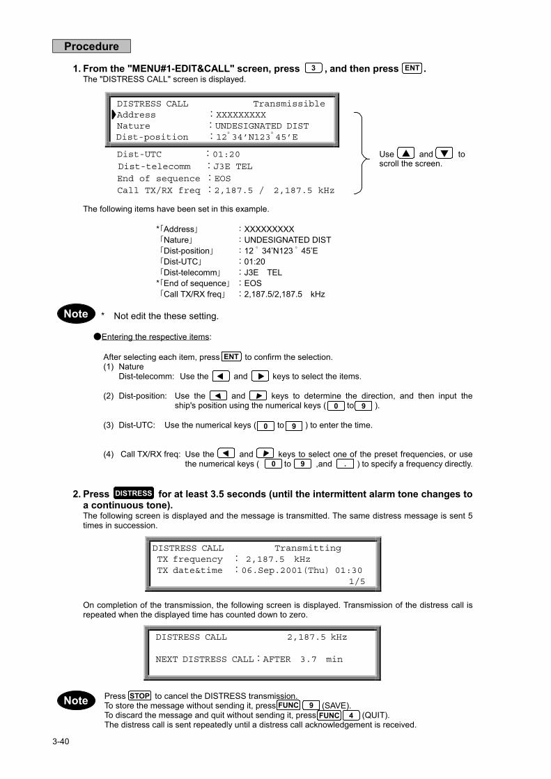
3-40
DISTRESS CALL Transmissible Address :XXXXXXXXX Nature :UNDESIGNATED DIST Dist-position :12゚34’N123゚45’E
Dist-UTC :01:20
Dist-telecomm :J3E TEL End of sequence :EOS Call TX/RX freq :2,187.5 / 2,187.5 kHz
Use and toscroll the screen.
Procedure
1. From the "MENU#1-EDIT&CALL" screen, press , and then press .The "DISTRESS CALL" screen is displayed.
The following items have been set in this example.
* Address XXXXXXXXXNature UNDESIGNATED DISTDist-position 12 ゚ 34’N123 ゚ 45’EDist-UTC :01:20Dist-telecomm :J3E TEL
* End of sequence :EOSCall TX/RX freq :2,187.5/2,187.5 kHz
* Not edit the these setting.
●Entering the respective items:
After selecting each item, press to confirm the selection.(1) Nature
Dist-telecomm: Use the and keys to select the items.
(2) Dist-position: Use the and keys to determine the direction, and then input theship's position using the numerical keys ( to ).
(3) Dist-UTC: Use the numerical keys ( to ) to enter the time.
(4) Call TX/RX freq: Use the and keys to select one of the preset frequencies, or usethe numerical keys ( to ,and ) to specify a frequency directly.
2. Press for at least 3.5 seconds (until the intermittent alarm tone changes toa continuous tone).The following screen is displayed and the message is transmitted. The same distress message is sent 5times in succession.
On completion of the transmission, the following screen is displayed. Transmission of the distress call isrepeated when the displayed time has counted down to zero.
Press to cancel the DISTRESS transmission.To store the message without sending it, press (SAVE).To discard the message and quit without sending it, press (QUIT).The distress call is sent repeatedly until a distress call acknowledgement is received.
3 ENT
ENT
0 9
0 9
DISTRESS CALL Transmitting TX frequency : 2,187.5 kHz TX date&time :06.Sep.2001(Thu) 01:30 1/5
DISTRESS CALL 2,187.5 kHz
NEXT DISTRESS CALL:AFTER 3.7 min
DISTRESS
FUNC 9FUNC 4
STOP
▲ ▼
Note
Note
0 9 .

3-41
●About Distress CallsDistress calls, distress relay and distress acknowledgement functions are described here.
Distress Call TransmissionDistress type FORMAT CATEGOLY TELECOMMAND-1 Operating keys No. of transmissions
DISTRESS DISTRESS - - DISTRESS 5 successive transmissionswith intervals
DISTRESS DISTRESS - - CALL>DISTRESS 5 successive transmissionswith intervals
DISTRESS INDIVIDUALALL SHIPSGROUPAREA
DISTRESS J3E TEL, etc. CALL>DISTRESS Once only
DISTRESS RELAY INDIVIDUAL DISTRESS DISTRESS RELAY CALL>DISTRESS Once onlyDISTRESS RELAY ALL SHIPS DISTRESS DISTRESS RELAY CALL>DISTRESS Once onlyDISTRESS ACK ALL SHIPS DISTRESS DISTRESS ACK CALL Once only
Distress CallsWhen transmitting without editing and using only the key, the message with the contentspreviously compiled in the distress setting is transmitted. This message is transmitted five timessuccessively at 3.5- to 4.5-minute intervals.The following are two ways of distress transmitting after editing:1. Transmitting details of distress conditions
This transmission is made according to 3.5.3 (3), "DISTRESS CALL." The nature of the distress, theship's position, time, and communication method are transmitted. The message is transmitted five timessuccessively at 3.5- to 4.5-minute intervals.This is the primary method.
2. This transmission includes INDIVIDUAL, ALL SHIPS, GROUP, and AREA, and it is enabled when"DISTRESS" is selected for the CATEGORY. The contents of the message are the same as othermessages. This message is transmitted only once.
DISTRESS RELAY CALLThis transmission is made according to 3.5.3 (4), "DISTRESS RELAY CALL." The message to betransmitted can be edited by selecting "DISTRESS" for FORMAT and "DISTRESS RELAY" for CATEGORYin individual or all ships calls. However, the contents are the same. The received message is edited so that itis the same as the received distress message. It is then transmitted to a coastal station. This message istransmitted only once.
DISTRESS ACK CALLThis transmission is made according to 3.5.3 (2), "ACKNOWLEDGEMENT CALL (2-2)." The message is notcreated automatically because the contents need to be confirmed. The acknowledgement message isedited manually and then transmitted. It is necessary to edit the message to be transmitted according to thecontents of the received message. This message is transmitted only once by using key.
ATTENTION When a distress message is received, make the transmission according to "RECEPTION OF DSC DISTRESS ALERT".
DISTRESS
CALL
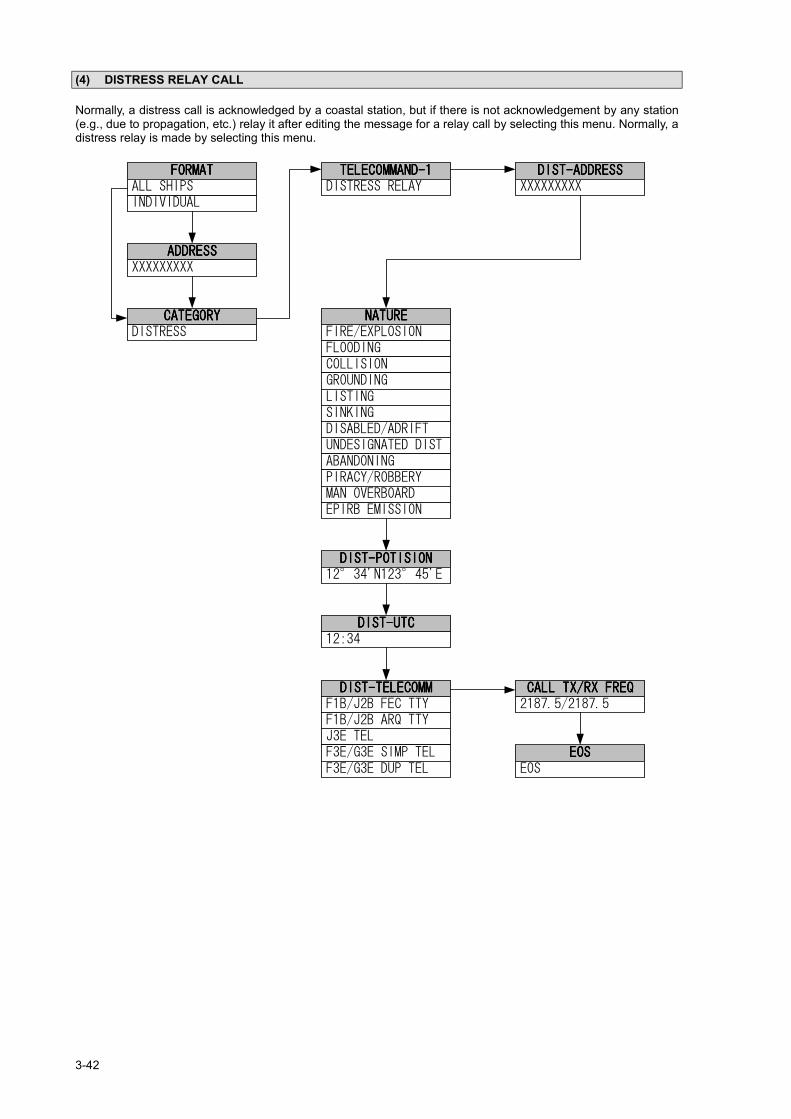
3-42
(4) DISTRESS RELAY CALL
Normally, a distress call is acknowledged by a coastal station, but if there is not acknowledgement by any station(e.g., due to propagation, etc.) relay it after editing the message for a relay call by selecting this menu. Normally, adistress relay is made by selecting this menu.

3-43
ALL SHIP’S DIST-RELAY Dist-address :XXXXXXXXX Nature :UNDESIGNATED DIST Dist-position :12゚34’N123゚45’E
Dist-UTC :01:20Dist-telecomm :J3E TEL Call TX/RX freq: 2,187.5 / 2,187.5 kHz
Use and toscroll the screen.
Procedure
Example: Procedure of a distress relay call to all ships
1. From the "MENU#1-EDIT&CALL" screen, press , and then press .The "DISTRESS RELAY CALL" screen is displayed.
1. Select 1 to relay the call to all ships and coastal stations.2. Select 2 to relay the call to an individual ship or coastal station.
2. Press . and then press .The "ALL SHIPS DIST-RELAY" screen is displayed.
The following items have been set in this example.
Dist-address :XXXXXXXXXNature UNDESIGNATED DISTDist-position 12 ゚ 34’N123 ゚ 45’EDist-UTC :01:20Dist-telecomm :J3E TELCall TX/RX freq :2,187.5/2,187.5 kHz
●Entering the respective items:
After selecting each item, press to confirm the selection.(1) Dist-address: Use the numerical keys ( to ) to enter the address of the receiving
station (ship or coastal station).(2) Nature
Dist-telecomm: Use the and keys to select the items.
(3) Dist-position: Use the and keys to determine the direction, and then input theship's position using the numerical keys ( to ).
(4) Dist-UTC: Use the numerical keys ( to ) to enter the time.
(4) Call TX/RX freq: Use the and keys to select one of the preset frequencies, or usethe numerical keys ( to ,and ) to specify a frequency directly.
4 ENT
ENT
0 9
0 9
DISTRESS RELAY CALL Select no.__ 1.ALL SHIP’S DIST rly EDIT 2.INDIVIDUAL DIST rly EDIT
1 ENT
0 9
▲ ▼
Note
0 9 .

3-44
3. Press , and then open the cover on the left and press for at least 3seconds (until the intermittent alarm tone changes to a continuous tone).The following screen is displayed and the message is transmitted.
・ Press to cancel the DISTRESS transmission.・ To discard the message and quit without sending it, press (QUIT). Unable to save the message.
CALL
ALL SHIP’S DIST-RELAY Transmitting TX frequency : 2,187.5 kHz TX date&time : 06.Sep.2001(Thu) 01:30
DISTRESS
FUNC 4STOPNote

3-45
(5) AUTO/SEMI-AUTO CALL
This mode is available only to coastal stations where the telephone on board can be connected on-line to a publicline on the land after DSC communication on the MF/HF band.

3-46
Use and toscroll the screen.
Procedure
1. From the "MENU#1-EDIT&CALL" screen, press , and then press .The "AUTO/SEMI-AUTO CALL" screen is displayed.
The following items have been set in this example.
Address :XXXXXXXXXTelecommand-1 J3E TELTelecommand-2 :NO INFORMATIONShip’s position :12 ゚ 34’N123 ゚ 45’ETelephone no. :04224507XXCall TX/RX freq :4,208.0/4,219.5 kHz
●Entering the respective items:
After selecting each item, press to confirm the selection.(1) Address: Use the numerical keys ( to ) to enter the address of the receiving station
(ship or coastal station).(2) Telecommand-1: Use the and keys to select the items.
Telecommand-2
(3) Ship's-position: Use the and keys to determine the direction, and then input theship's position using the numerical keys ( to ).
(4) Telephone no. Use the numerical keys ( to ) to enter the telephone number.
(5) Call TX/RX freq: Use the and keys to select one of the preset frequencies, or usethe numerical keys ( to ,and ) to specify a frequency directly.
(6) Other settings:・"Work TX/RX freq": Use the numerical keys ( to , and ) to directly specify a
frequency.
・Switching from "Ship's position" to "Work TX/RX freq": Press (FREQ).
・Switching from "Work TX/RX freq" to "Ship's position": Press (POS).
ATTENTIONThis call requires the auto/semi-auto call service of a coastal station.Please ask the coastal station you use for details.
AUTO/SEMI-AUTO CALL Transmissible Address :XXXXXXXXX Telecommand-1 :J3E TEL Telecommand-2 :NO INFORMATION
Ship’s position:12 ゚ 34’N123 ゚ 45’E Telephone no. :04224507XX Call TX/RX freq: 4,208.0/4,219.5kHz
0 9
0 9
FUNC 6
FUNC 5
ENT
5 ENT
0 9
▲ ▼
0 9 .
0 9 .

3-47
2. Press The following screen is displayed and the message is transmitted.
If the tuner is not tuned to the transmission frequency, the "tuner mismatch!!" warning message isdisplayed. Press to tune the tuner, then transmit the message.
When the transmission is completed, the following screen is displayed. After a brief interval, operationreturns to the "MENU#1-EDIT&CALL" screen.
To discard the message and quit without sending it, press (QUIT).To store a message without sending it, press (SAVE).
CALL
AUTO/SEMI-AUTO CALL Transmitting TX frequency : 4,208.0 kHz TX date&time :06.Sep.2001(Thu) 01:30
AUTO/SEMI-AUTO CALL Send Completed TX frequency : 4,208.0 kHz TX date&time :06.Sep.2001(Thu) 01:30
FUNC 9
ENT
FUNC 4
Note
Note

3-48
(6) ALL SHIPS CALL
An all ships call is transmitted to all ships. Normally, this feature is used to acknowledge when a distress call isreceived and a distress acknowledgement from a coastal station has not been received in response.

3-49
ALL SHIPS CALL Category :DISTRESS Telecommand-1 :DISTRESS RELAY Dist-address :XXXXXXXXX
Nature :UNDESIGNATED DIST Dist-position :12 ゚ 34’N123 ゚ 45’E Dist-UTC :01:20 Dist-telecomm :J3E TEL Call TX/RX freq: 4,208.0 / 4,208.0 kHz
Use and toscroll the screen.
Procedure
Example: Procedure for a distress relay call to all ships
1. From the "MENU#1-EDIT&CALL" screen, press , and then press .The "ALL SHIPS CALL" screen is displayed.
The following items have been set in this example.
Category :DISTRESSTelecommand-1 :DISTRESS RELAYDist-address :XXXXXXXXXNature UNDESIGNATED DISTDist-position 12 ゚ 34’N123 ゚ 45’EDist-UTC :01:20Dist-telecomm :J3E TELCall TX/RX freq :4,208.0 / 4,208.0 kHz
●Entering the respective items:
After selecting each item, press to confirm the selection.(1) Dist-address: Use the numerical keys ( to ) to enter the address of the receiving
station (ship or coastal station).(2) Category
Telecommand-1: Use the and keys to select the items.NatureDist-telecomm
(3) Dist-position: Use the and keys to select the bearing, and then input the valueusing the numerical keys ( to ).
(4) Dist-UTC: Use the numerical keys ( to ) to enter the time.
(5) Call TX/RX freq: Use the and keys to select one of the preset frequencies.Alternatively, use the numerical keys ( to , and ) to directlyspecify a frequency.
Set the "Work TX/RX freq" to a frequency in the same band as the "Call TX/RX freq".
6 ENT
0 9 .
ENT
0 9
0 9
0 9
▲ ▼
Note

3-50
2. Press , then open the cover on the left and press for at least 3seconds (until the intermittent alarm tone changes to a continuous tone).The following screen is displayed and the set distress message is transmitted.
When the transmission is completed, the following screen is displayed and the message is automaticallysaved. After a brief interval, operation returns to the "MENU#1-EDIT&CALL" screen.
See (1), "Individual Call" for how to send a general message.To store a message without sending it, press (SAVE).To discard the message and quit without sending it, press (QUIT).
CALL
ALL SHIPS CALL Transmitting TX frequency: 4,208.0 kHz TX date&time:06.Sep.2001(Thu) 01:26
DISTRESS
ALL SHIPS CALL Send Completed TX frequency : 4,208.0 kHz TX date&time :06.Sep.2001(Thu) 01:26
FUNC 9FUNC 4
Note

3-51
(7) GROUP CALL
This process is used to edit and transmit a message to a specific group.
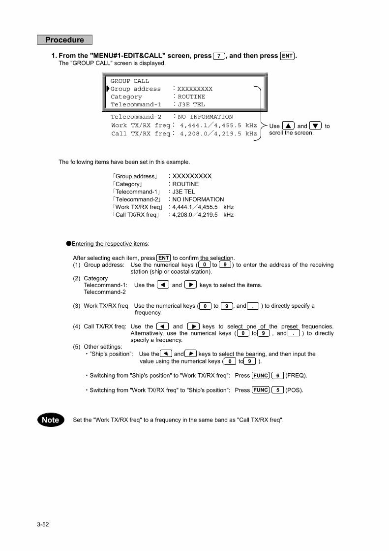
3-52
GROUP CALL Group address :XXXXXXXXX Category :ROUTINE Telecommand-1 :J3E TEL
Telecommand-2 :NO INFORMATION Work TX/RX freq: 4,444.1/4,455.5 kHz Call TX/RX freq: 4,208.0/4,219.5 kHz
Use and toscroll the screen.
Procedure
1. From the "MENU#1-EDIT&CALL" screen, press , and then press .The "GROUP CALL" screen is displayed.
The following items have been set in this example.
Group address :XXXXXXXXXCategory :ROUTINETelecommand-1 J3E TELTelecommand-2 :NO INFORMATIONWork TX/RX freq :4,444.1/4,455.5 kHzCall TX/RX freq :4,208.0/4,219.5 kHz
●Entering the respective items:
After selecting each item, press to confirm the selection.(1) Group address: Use the numerical keys ( to ) to enter the address of the receiving
station (ship or coastal station).(2) Category
Telecommand-1: Use the and keys to select the items.Telecommand-2
(3) Work TX/RX freq Use the numerical keys ( to , and ) to directly specify a frequency.
(4) Call TX/RX freq: Use the and keys to select one of the preset frequencies.Alternatively, use the numerical keys ( to , and ) to directlyspecify a frequency.
(5) Other settings:・”Ship's position”: Use the and keys to select the bearing, and then input the value using the numerical keys ( to ).
・Switching from "Ship's position" to "Work TX/RX freq": Press (FREQ).
・Switching from "Work TX/RX freq" to "Ship's position": Press (POS).
Set the "Work TX/RX freq" to a frequency in the same band as "Call TX/RX freq".
7 ENT
0 9
0 9
0 9 .
FUNC 6
FUNC 5
ENT
▲ ▼
0 9 .
Note

3-53
2. Press .The following screen is displayed and the message is transmitted.
If the tuner is not tuned to the transmission frequency, the "tuner mismatch!!" warning message isdisplayed. Press to tune the tuner, then transmit the message.
When the transmission is completed, the following screen is displayed. After a brief interval, operationreturns to the "MENU#1-EDIT&CALL" screen.
To discard the message and quit without sending it, press (QUIT).To store a message without sending it, press (SAVE).
CALL
GROUP CALL Transmitting TX frequency : 4,208.0 kHz TX date&time :06.Sep.2001(Thu) 01:30
GROUP CALL Send Completed TX frequency : 4,208.0 kHz TX date&time :06.Sep.2001(Thu) 01:30
FUNC 9
ENT
FUNC 4
Note
Note

3-54
(8) AREA CALL
This procedure is used to edit and transmit a call message to ships in the specified area.

3-55
Use and toscroll the screen.
●Area call setting
An area call is received by all ships navigating in a designated geographical area. For the area of calledstations (PARTY AD), latitude, longitude, deviation latitude (from North to South), and deviation longitude(from West to East) are necessary. The area of the shaded part is designated in the figure below.
N Reference point 20°
Deviation latitude (DLAT)=10°
10°
W E 120° 170° S Deviation longitude (LONG)=50°
First, select the direction from N.E. (North-East), N.W. (North-West), S.E. (South-East), and S.W. (South-West). In this example, the direction is N.E.
PARTY AD :N E DLAT LONG /
Next, enter 20°, 120°, making this latitude 20° and longitude 120°.
PARTY AD :N20E120 DLAT LONG /
In addition, as the deviation latitude (DLAT) and deviation longitude (LONG) are, respectively, 10° and 50°,input 1050..
PARTY AD :N20E120DLAT10LONG50
Finally, press to confirm the area.
Up to 99° can be input for deviation latitude and deviation longitude.Ranges that include the Arctic Pole or Antarctic Pole cannot be specified.
Procedure
1. From the "MENU#1-EDIT&CALL" screen, press , and then press .The "AREA CALL" screen is displayed.
ENT
AREA CALL Transmissible Area :N20E120DLAT10LONG50 Category :ROUTINE Telecommand-1 :J3E TEL
Telecommand-2 :NO INFORMATION Work TX/RX freq : 4,444.1/4,455.5 kHz Call TX/RX freq : 4,208.0/4,219.5 kHz
8 ENT
▲ ▼
Note

3-56
The following items have been set in this example.
Area :N20E120DLAT10LONG50Category :ROUTINETelecommand-1 J3E TELTelecommand-2 :NO INFORMATIONWork TX/RX freq :4,444.1/4,455.5 kHzCall TX/RX freq :4,208.0/4,219.5 kHz
●Entering the respective items:
After selecting each item, press to confirm the selection.(1) Category
Telecommand-1: Use the and keys to select the items.Telecommand-2
(2) AreaShip's position: Use the and keys to select the bearing, and then input the value
using the numerical keys ( to ).
(3) Call TX/RX freq: Use the and keys to select one of the preset frequencies.Alternatively, use the numerical keys ( to , and ) to directlyspecify a frequency.
(4) Other settings:・"Work TX/RX freq": Use the numerical keys ( to , and ) to directly specify a
frequency.
・Switching from "Ship's position" to "Work TX/RX freq": Press (FREQ).
・Switching from "Work TX/RX freq" to "Ship's position": Press (POS).
Set the "Work TX/RX freq" to a frequency in the same band as "Call TX/RX freq".
2. Press .The following screen is displayed and the message is transmitted.
If the tuner is not tuned to the transmission frequency, the "tuner mismatch!!" warning message isdisplayed. Press to tune the tuner, then transmit the message.
When the transmission is completed, the following screen is displayed. After a brief interval, operationreturns to the "MENU#1-EDIT&CALL" screen.
To discard the message and quit without sending it, press (QUIT).To store a message without sending it, press (SAVE).
0 9
0 9 .
FUNC 6
FUNC 5
ENT
CALL
AREA CALL Transmitting TX frequency : 4,208.0 kHz TX date&time :06.Sep.2001(Thu) 01:30
AREA CALL Send Completed TX frequency : 4,208.0 kHz TX date&time :06.Sep.2001(Thu) 01:30
FUNC 9
ENT
FUNC 4
0 9 .
Note
Note
Note

3-57
(9) POSITION REQUEST CALL
This feature is used when a coastal station wants to know a ship's position, or two ships want to know each other'sposition.

3-58
Procedure
1. From the "MENU#1-EDIT&CALL" screen, press , and then press .The "POSITION REQUEST" screen is displayed.
The following items have been set in this example.
Address :XXXXXXXXXCall TX/RX freq :4,208.0/4,219.5 kHz
●Entering the respective items:
After selecting each item, press to confirm the selection.(1) Address: Use the numerical keys ( to ) to enter the address of the receiving station
(ship or coastal station).
(2) Call TX/RX freq: Use the and keys to select one of the preset frequencies.Alternatively, use the numerical keys ( to , and ) to directlyspecify a frequency.
2. Press .The following screen is displayed and the message is transmitted.
If the tuner is not tuned to the transmission frequency, the "tuner mismatch!!" warning message isdisplayed. Press to tune the tuner, then transmit the message.
When the transmission is completed, the following screen is displayed. After a brief interval, operationreturns to the "MENU#1-EDIT&CALL" screen.
To discard the message and quit without sending it, press (QUIT).To store a message without sending it, press (SAVE).
POSITION REQUEST Address :XXXXXXXXX Call TX/RX freq : 4,208.0/4,219.5 kHz
9 ENT
0 9 .
ENT0 9
CALL
POSITION REQUEST Transmitting TX frequency : 4,208.0 kHz TX date&time :06.Sep.2001(Thu) 01:30
POSITION REQUEST Send Completed TX frequency : 4,208.0 kHz TX date&time :06.Sep.2001(Thu) 01:30
FUNC 9
ENT
FUNC 4
Note
Note

3-59
(10) POLLING CALL
This feature is used to confirm that the destination station exists within a communication area.

3-60
Procedure
1. From the "MENU#1-EDIT&CALL" screen, press , and then press .The "POLLING CALL" screen is displayed.
The following items have been set in this example.
Address :XXXXXXXXXCall TX/RX freq :4,208.0/4,219.5 kHz
●Entering the respective items:
After selecting each item, press to confirm the selection. (1) Adress: Use the numerical keys ( to ) to enter the address of the receiving station
(ship or coastal station).
(2) Call TX/RX freq: Use the and keys to select one of the present frequencies. Alternatively, use the numerical keys ( to ,and ) to directly Specify a frequency.
2. Press .The following screen is displayed and the message is transmitted.
If the tuner is not tuned to the transmission frequency, the "tuner mismatch!!" warning message isdisplayed. Press to tune the tuner, then transmit the message.
When the transmission is completed, the following screen is displayed. After a brief interval, operationreturns to the "MENU#1-EDIT&CALL" screen.
To discard the message and quit without sending it, press (QUIT).To store a message without sending it, press (SAVE).
POLLING CALL Address :XXXXXXXXX Call TX/RX freq: 4,208.0/4,219.5 kHz
1 ENT0
CALL
POLLING CALL Transmitting TX frequency : 4,208.0 kHz TX date&time :06.Sep.2001(Thu) 01:30
POLLING CALL Send Completed TX frequency : 4,208.0 kHz TX date&time :06.Sep.2001(Thu) 01:30
FUNC 9
ENT
FUNC 4
Note
Note
0 9 .
ENT0 9
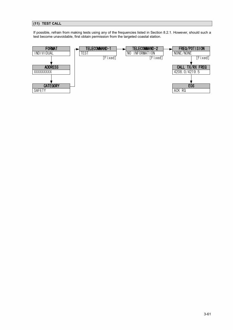
3-61
(11) TEST CALL
If possible, refrain from making tests using any of the frequencies listed in Section 8.2.1. However, should such atest become unavoidable, first obtain permission from the targeted coastal station.

3-62
Procedure
1. From the "MENU#1-EDIT&CALL" screen, press , and then press .The "TEST CALL" screen is displayed.
The following items have been set in this example.
Address :XXXXXXXXXCall TX/RX freq :4,208.0/4,219.5 kHz
2. Press .The following screen is displayed and the message is transmitted.
If the tuner is not tuned to the transmission frequency, the "tuner mismatch!!" warning message isdisplayed. Press to tune the tuner, then transmit the message.
When the transmission is completed, the following screen is displayed. After a brief interval, operationreturns to the "MENU#1-EDIT&CALL" screen.
To discard the message and quit without sending it, press (QUIT).To store a message without sending it, press (SAVE).Normally, the message content is predetermined so that the message is sent to a coastal station.
TEST CALL Transmissible Address :XXXXXXXXX Call TX/RX freq: 4,208.0/4,219.5 kHz
1 ENT1
CALL
TEST CALL Transmitting TX frequency : 4,208.0 kHz TX date&time :06.Sep.2001(Thu) 01:30
ENT
TEST CALL Send Completed TX frequency : 4,208.0 kHz TX date&time :06.Sep.2001(Thu) 01:30
FUNC 9FUNC 4
Note
Note

3-63
3.5.4 Other Functions
(1) Frequency scanning
When the JSB-196/196GM Radiotelephone is connected, scanning 1 reception among the six specifiedfrequencies is available. When the NCT-196N automatic acknowledgement setting 2 is ON and a messagerequiring acknowledgment is received 3, the acknowledgement message is transmitted on a transmit frequencythat is paired with the reception frequency.This section describes how to set up the scanning function.
1 The selected reception frequency (scanning frequency) is switched at intervals of about 0.3 sec.2 See "● AUTO ACKNOWLEDGEMENT SETUP" in Section 3.5.4 (4), "Other Settings."3 Indicates that the "EOS" of the message compiled in steps (1) to (11) of Section 3.5.3, "Transmitting Messages" is set to
ACK RQ (acknowledgement required).
● Starting and stopping scanning
The scanning frequency must be specified before starting or stopping scanning. Refer to "Specifying the scanningfrequency" below.
Procedure
1. Press , and then (SCAN).Scanning starts for the specified frequencies.
2. Press , and then (SCAN).Scanning stops.
● Specifying the scanning frequency
Procedure
1. Check that the "DSC watching" screen is displayed.
If the "DSC watching" screen is not displayed, press 3 times in succession to switch to the"DSC watching" screen.When the mark is displayed on the screen, no printer is connected to the NCT-196.
1FUNC
1FUNC
DSC watching 06.Sep.2001(Thu) 01:26 99゚99’N999゚99’E SPEED:__._KT at 88:88
Self-ID = XXXXXXXXX [UTC]
STOP
P
Note

3-64
MENU #2-READOUT&SETUP Select no. 1.Received distress message readout 2.Received others message readout 3.Setup
4.Self test
SETUP Select no. 1. Date&time edit 2. Position edit 3. Calling frequency registration
4. Address registration 5. Distress setup 6. Others alarm setup 7. Automatic acknowledgement setup 8. Scanning setup 9. Watchkeeping receiver setup
Use and toscroll the screen.
Use and toscroll the screen.
2. Press .The "MENU#1-EDIT&CALL" screen is displayed.
3. Press again.The "MENU#2-READOUT&SETUP" screen is displayed.
4. Press , and then press .The "SETUP" screen is displayed.
MENU
MENU #1 -EDIT&CALL Select no. 1. Individual call 2. Acknowledgement call 3. Distress call
4. Distress relay call 5. Auto / semi-auto call 6. All ships call Use and to scroll the screen. 7. Group call 8. Area call 9. Position request 10. Polling call 11. Test call
▲ ▼
MENU
3 ENT
▲ ▼
▲ ▼

3-65
SCANNING SETUP [1] 1,610.0 / 1,615.0 kHz [2] 2,000.0 / 2,000.0 kHz [3] 3,000.0 / 3,000.0 kHz
[4] 4,208.0 / 4,219.0 kHz [5] 5,000.0 / 5,000.0 kHz [6] 6,000.0 / 6,000.0 kHz
TX RX
Use and toscroll the screen.
5. Press , and then press .The "SCANNING SETUP " screen is displayed.
6. Enter the "Transmit frequency/Receive frequency" pair for each channel.
Press and then to cancel a setting and leave it blank.
7.On completion of entering the data, press , and then press (SAVE).
Press to tune the tuner and then return to the "SETUP" screen.
Press to abort tuning and return to the "SETUP" screen.
Press , and then press (QUIT) to cancel this menu.
8 ENT
ENTCLR
Tune regist frequency? [ENT] key :TUNE [STOP] key:NO TUNE
9FUNC
ENT
STOP
FUNC 4
▲ ▼
Note
Note

3-66
SETUP Select no. 1. Date&time edit 2. Position edit 3. Calling frequency registration
4. Address registration 5. Distress setup 6. Others alarm setup 7. Automatic acknowledgement setup 8. Scanning setup 9. Watchkeeping receiver setup
CALLING FREQUENCY REGISTRATION (TX/RX) [1] 12,345.6/12,356.7 kHz ( )[2] NONE / NONE kHz ( ) [3] NONE / NONE kHz ( )
[4] NONE / NONE kHz ( ) [5] NONE / NONE kHz ( ) [6] NONE / NONE kHz ( )
Use and toscroll the screen.
Use and toscroll the screen.
(2) Useful Functions
The NCT-196N register up to six party addresses with a shorthand name, and up to six calling frequencies.The registered contents are retrieved by using and when compiling a call message, obviating the need toenter numbers.The addresses and calling frequencies are stored from the "SETUP" screen. See steps 1 to 3 of (1) Specifying thescanning frequency" for how to display the "SETUP" screen.
● Registering a calling frequency
Procedure
1. From the "SETUP" screen, press , and then press .The "CALLING FREQUENCY REGISTRATION (TX/RX)" screen is displayed.
2. Enter the "Transmit frequency/Receive frequency (name)" for each channel.Enter the transmit frequency/receive frequency pair using to and .
Enter (name) as follows: 1. Selecting characters: Use and to select characters inside theparentheses ().
2. Confirming characters: After selecting each character, press .
To go to the next channel or skip to the next channel without specifying a name, press two times.
3. On completion of entering the data, press , and then press (SAVE).
Press to tune the tuner and then return to the "SETUP" screen.
Press to abort tuning and return to the "SETUP" screen.
Press to delete registered calling frequency.
Press , and then press (QUIT) to cancel this menu.
3 ENT
0 9 .
ENT
ENT
Tune regist frequency? [ENT] key : TUNE [STOP] key: NO TUNE
9FUNC
ENT
STOP
▲ ▼
▲ ▼
FUNC 4Note
CLRNote

3-67
ADDRESS REGISTRATION [1] _ ( ) [2] ( ) [3] ( )
[4] ( )[5] ( )
[6] ( )
Use and toscroll the screen.
● Registering an address
Procedure
1. From the "SETUP" screen, press , and then press .The "ADDRESS REGISTRATION" screen is displayed.
2. Enter the address (name) for each channel.
Enter the address using to and .
Enter (name) as follows: 1. Selecting characters: Use and to select characters inside theparentheses ().
2. Confirming characters: After selecting each character, press .
To go to the next channel or skip to the next channel without specifying a name, press two times.
3. On completion of entering the data, press , and then press (SAVE).
Press to delete registered address.
Press , and then press (QUIT) to cancel this menu.
4 ENT
0 9 .
ENT
ENT
9FUNC
▲ ▼
FUNC 4Note
CLRNote

3-68
PRINT MENU 1.ALL RECEIVED DISTRESS MESSAGES 2.ALL RESEIVED OTHERS MESSAGES 3.ALL EDIT/CALL MESSAGES
4.ALL SETUP INFORMATION Use and toscroll the screen.
(3) Printing function
When a printer is connected, all received messages are printed out upon reception. In addition, it is also possible toprint out other stored information.
The printing function enables the followings and the procedures are described in this section.The printing of all of the files, which classification is selected from the print menu.The printing of a selected file, which contents is displayed on screen.
Printing from the print menu (batch printing of multiple files)
Procedure
1. Check that the "DSC watching" screen is displayed.
If the "DSC watching" screen is not displayed, press 3 times in succession to switch to the"DSC watching" screen.When the mark is displayed on the screen, no printer is connected to the NCT-196.
2. Press , and then (PRINT).The "PRINT MENU" screen is displayed.
3. Select the item to be printed, and then press .Printing starts.
4. When printing is finished, press , and then press (QUIT).Operation returns to the "DSC watching" screen.
● Printing a specified file
Procedure
1. Press once or twice.The "MENU#1-EDIT&CALL" screen or "MENU#2-READOUT&SETUP" screen is displayed.
2. Enter the number of the file to be printed, and then press .The file content is displayed.
3. Press , and then press (PRINT).The displayed file is printed.
4. When printing is finished, press , and then press (QUIT).Operation returns to the"MENU#1-EDIT&CALL" screen or "MENU#2-READOUT&SETUP" screen.
DSC watching 06.Sep.2001(Thu) 01:26 12゚34’N123゚45’E SPEED:12.4KT at 01:26
Self-ID = XXXXXXXXX [UTC]
STOP
3FUNC
ENT
FUNC 4
MENU
ENT
3FUNC
FUNC 4
P
▲ ▼
Note

3-69
SETUP Select no. 1. Date&time edit 2. Position edit 3. Calling frequency registration
4. Address registration 5. Distress setup 6. Others alarm setup 7. Automatic acknowledgement setup 8. Scanning setup 9. Watchkeeping receiver setup
Use and toscroll the screen.
(4) Other settings
The following procedures are explained in this section:How to compile the message transmitted when pressing . How to set the auto acknowledgement to ON/OFF for an acknowledgment required call Other settings.
ATTENTION Pay close attention when inputting and/or modifying the information described in this section as the contents are critical for operating the DSC. If these operations are unclear, contact JRC or our agents.
The data is input using the "SETUP" screen. See the above-mentioned “Specifying the scanning frequency" 1-3steps of “(1) Frequency scanning” for how to display the "SETUP" screen. However regarding the "DATE&TIMEEDIT" and "POSITION EDIT" settings in this setup menu, see Section 4.2 "Setting Position and Time Data".
DISTRESS
▲ ▼

3-70
● DISTRESS SETUP
This function is used to compile a distress call message to be transmitted by pressing .
Nature : UNDESIGNATED DIS ← 【FIXED】 Nature of the distress (undesignated distress)Position : 12 ゚ 34’N123 ゚ 45’E ← 【AUTO or MANUAL】The navigation equipment data or manually
entered data.Time : 19:00 ← 【AUTO or MANUAL】The navigation equipment data or manually
entered data.Telecommand : J3E TEL ← 【VARIABLE】 The data set using this menu.Tx frequency : 2187.5kHz ← 【VARIABLE】 The data set using this menu.
"Telecommand" shows the follow-on communication mode with the RCC that received the distress message.Normally, select either radiotelephone mode or MF/HF ARQ communication (F1B/J2B ARQ)."Tx frequency" shows a transmission frequency for DSC distress message calls. When the radio equipment is setto 2187.5 or 8414.5kHz, those frequencies take priority.
Procedure
1. From the "SETUP" screen, press and then press .The "DISTRESS SETUP" screen is displayed.
2. Enter each item.
Use and to change a setting and and to move the cursor and select the item.Press to confirm a setting.See Section 4.3.3 (3), "Distress Call" for items for which "Telecommand" can be selected.
3. On completion of entering the data, press , and then press (SAVE).Operation returns to the "SETUP" screen.
Press , and then press (QUIT) to cancel this menu.
5 ENT
DISTRESS SETUP Dist-telecomm : J3E TEL Dist-TX/RX freq: 2,187.5kHz
9FUNC
▼▲ENT
DISTRESS
FUNC 4Note
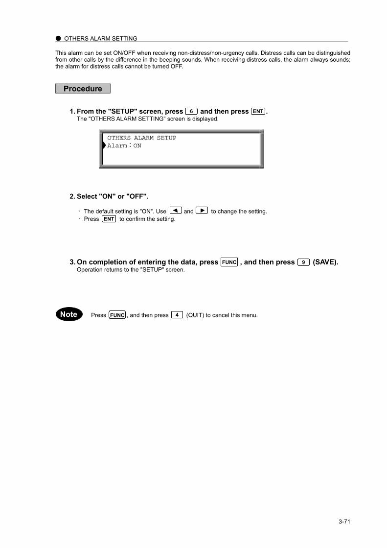
3-71
● OTHERS ALARM SETTING
This alarm can be set ON/OFF when receiving non-distress/non-urgency calls. Distress calls can be distinguishedfrom other calls by the difference in the beeping sounds. When receiving distress calls, the alarm always sounds;the alarm for distress calls cannot be turned OFF.
Procedure
1. From the "SETUP" screen, press and then press .The "OTHERS ALARM SETTING" screen is displayed.
2. Select "ON" or "OFF".
The default setting is "ON". Use and to change the setting.Press to confirm the setting.
3. On completion of entering the data, press , and then press (SAVE).Operation returns to the "SETUP" screen.
Press , and then press (QUIT) to cancel this menu.
6 ENT
OTHERS ALARM SETUP Alarm:ON
ENT
9FUNC
FUNC 4Note

3-72
● AUTOMATIC ACKNOWLEDGEMENT SETUP
The DSC terminal can be set to automatically send back an acknowledgement call (with ACK BQ for EOS) whenreceiving a DSC call with ACK RQ for EOS. However, when the CATEGORY is DISTRESS, URGENCY, orSAFETY, no acknowledgement is made automatically, even though ACK RQ is specified for EOS.Acknowledgement is made manually for all distress calls.
Procedure
1. From the "SETUP" screen, press and then press .The "AUTOMATIC ACKNOWLEDGEMENT SETUP" screen is displayed.
2. Select "ON" or "OFF".
The default setting is "ON". Use and to change the setting.Press to confirm the setting.
3. On completion of entering the data, press , and then press (SAVE).Operation returns to the "SETUP" screen.
Press , and then press (QUIT) to cancel this menu.
7 ENT
AUTOMATIC ACKNOWLEDGEMENT SETUP Acknowledgement:ON
ENT
9FUNC
FUNC 4Note

3-73
WATCHKEEPING RECEIVER SETUP CH1. 2187.5kHz : ON(const) CH2. 4207.5kHz : ON CH3. 6312.0kHz : OFF
CH4. 8414.5kHz : ON(const) CH5. 12577.0kHz : OFF CH6. 16804.5kHz : ON
Use and toscroll the screen.
● WATCHKEEPING RECEIVER SETUP
This procedure sets the Watch-keeping receiver's scanning frequency. The 2187.5kHz and 8414.5kHz frequenciesare preselected; here, frequencies are selected for the other four channels.The "DISTRESS FREQUENCY" lamps (on the front panel) are turned ON/OFF for each set channel. The lamps for2187.5kHz and 8414.5kHz are always ON.
Procedure
1. From the "SETUP" screen, press and then press .The "WATCHKEEPING RECEIVER SETUP" screen is displayed.
2. Select "ON" or "OFF".
The default setting is "ON". Use and to change the setting.Press to confirm the setting.The corresponding lamp for that frequency is turned ON or OFF according to the setting.
3. On completion of entering the data, press , and then press (SAVE).Operation returns to the "SETUP" screen.
Press , and then press (QUIT) to cancel this menu.
9 ENT
ENT
9FUNC
▲ ▼
FUNC 4Note
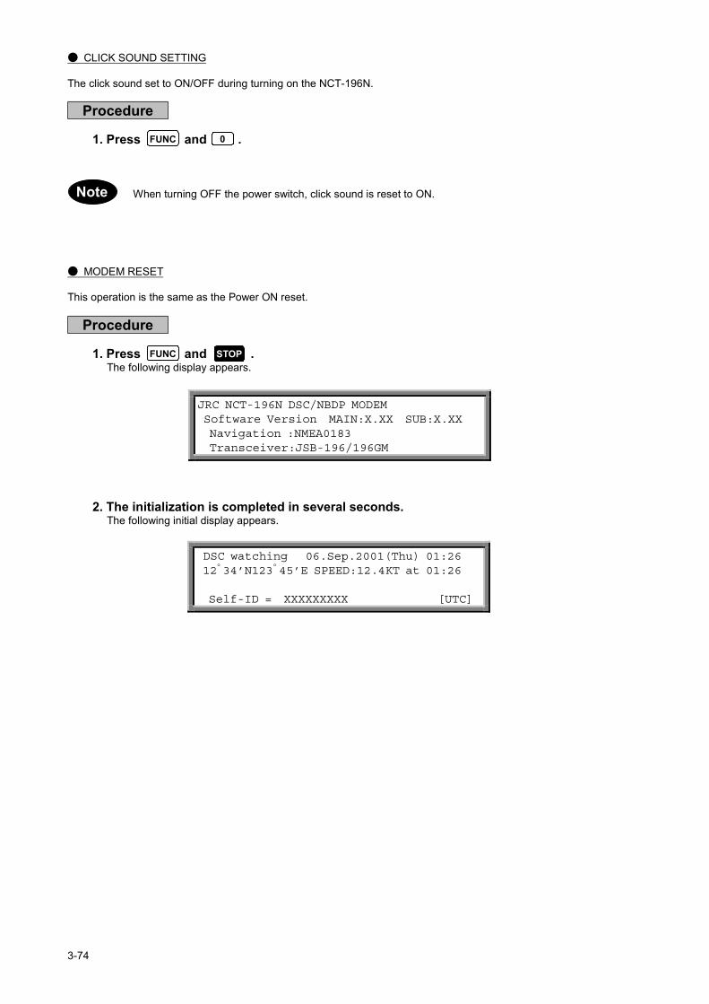
3-74
● CLICK SOUND SETTING
The click sound set to ON/OFF during turning on the NCT-196N.
Procedure
1. Press and .
When turning OFF the power switch, click sound is reset to ON.
● MODEM RESET
This operation is the same as the Power ON reset.
Procedure
1. Press and .The following display appears.
2. The initialization is completed in several seconds.The following initial display appears.
0FUNC
FUNC STOP
JRC NCT-196N DSC/NBDP MODEM Software Version MAIN:X.XX SUB:X.XX Navigation :NMEA0183 Transceiver:JSB-196/196GM
Note
DSC watching 06.Sep.2001(Thu) 01:26 12゚34’N123゚45’E SPEED:12.4KT at 01:26 Self-ID = XXXXXXXXX [UTC]
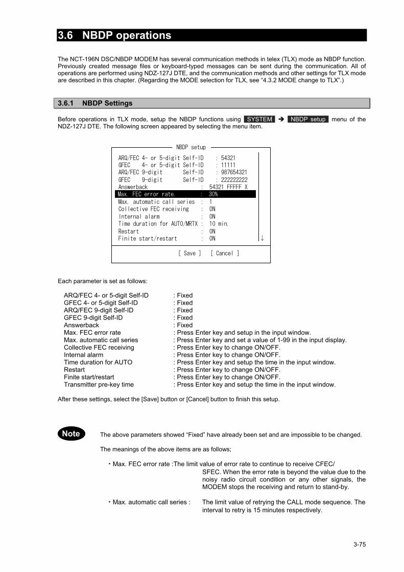
3-75
3.6 NBDP operations
The NCT-196N DSC/NBDP MODEM has several communication methods in telex (TLX) mode as NBDP function.Previously created message files or keyboard-typed messages can be sent during the communication. All ofoperations are performed using NDZ-127J DTE, and the communication methods and other settings for TLX modeare described in this chapter. (Regarding the MODE selection for TLX, see “4.3.2 MODE change to TLX”.)
3.6.1 NBDP Settings
Before operations in TLX mode, setup the NBDP functions using SYSTEM NBDP setup menu of theNDZ-127J DTE. The following screen appeared by selecting the menu item.
Each parameter is set as follows:
ARQ/FEC 4- or 5-digit Self-ID : FixedGFEC 4- or 5-digit Self-ID : FixedARQ/FEC 9-digit Self-ID : FixedGFEC 9-digit Self-ID : FixedAnswerback : FixedMax. FEC error rate : Press Enter key and setup in the input window.Max. automatic call series : Press Enter key and set a value of 1-99 in the input display.Collective FEC receiving : Press Enter key to change ON/OFF.Internal alarm : Press Enter key to change ON/OFF.Time duration for AUTO : Press Enter key and setup the time in the input window.Restart : Press Enter key to change ON/OFF.Finite start/restart : Press Enter key to change ON/OFF.Transmitter pre-key time : Press Enter key and setup the time in the input window.
After these settings, select the [Save] button or [Cancel] button to finish this setup.
The above parameters showed “Fixed” have already been set and are impossible to be changed.
The meanings of the above items are as follows;
・Max. FEC error rate :The limit value of error rate to continue to receive CFEC/SFEC. When the error rate is beyond the value due to thenoisy radio circuit condition or any other signals, theMODEM stops the receiving and return to stand-by.
・Max. automatic call series : The limit value of retrying the CALL mode sequence. Theinterval to retry is 15 minutes respectively.
Note
↓

3-76
・Collective FEC receiving : ON - CFEC receiving is permitted.OFF - CFEC receiving is prohibited.
・Internal alarm : ON - Internal alarm works.OFF - Internal alarm does not work.
・Time duration for AUTO : Time duration setting for AUTO mode
・Restart : ON - The MODEM tries to reconnect when the circuitestablished once is lost for 32 times ofsuccessive REPEAT condition
OFF - The MODEM returns to stand-by when thecircuit established once is lost for 32 times ofsuccessive REPEAT condition
・ Finite start/restart : ON - The MODEM returns to stand-by when thetimes of calling a partner station are reached to128 in ARQ mode.
OFF - The MODEM continues to call a partner stationeven if the times of calling are reached to 128in ARQ mode.
・Transmitter pre-key time : Adjustment of timing from KEY ON to signal output for thetransmitter electrical specification. It is also available toarrange the Send/Receive timing between long-rangedpartner station.
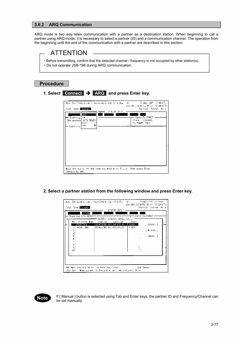
3-77
3.6.2 ARQ Communication
ARQ mode is two way telex communication with a partner as a destination station. When beginning to call apartner using ARQ mode, it is necessary to select a partner (ID) and a communication channel. The operation fromthe beginning until the end of the communication with a partner are described in this section.
Procedure
1. Select Connect ARQ and press Enter key.
2. Select a partner station from the following window and press Enter key.
If [ Manual ] button is selected using Tab and Enter keys, the partner ID and Frequency/Channel canbe set manually.
・Before transmitting, confirm that the selected channel / frequency is not occupied by other station(s).・Do not operate JSB-196 during ARQ communication.
ATTENTION
Note
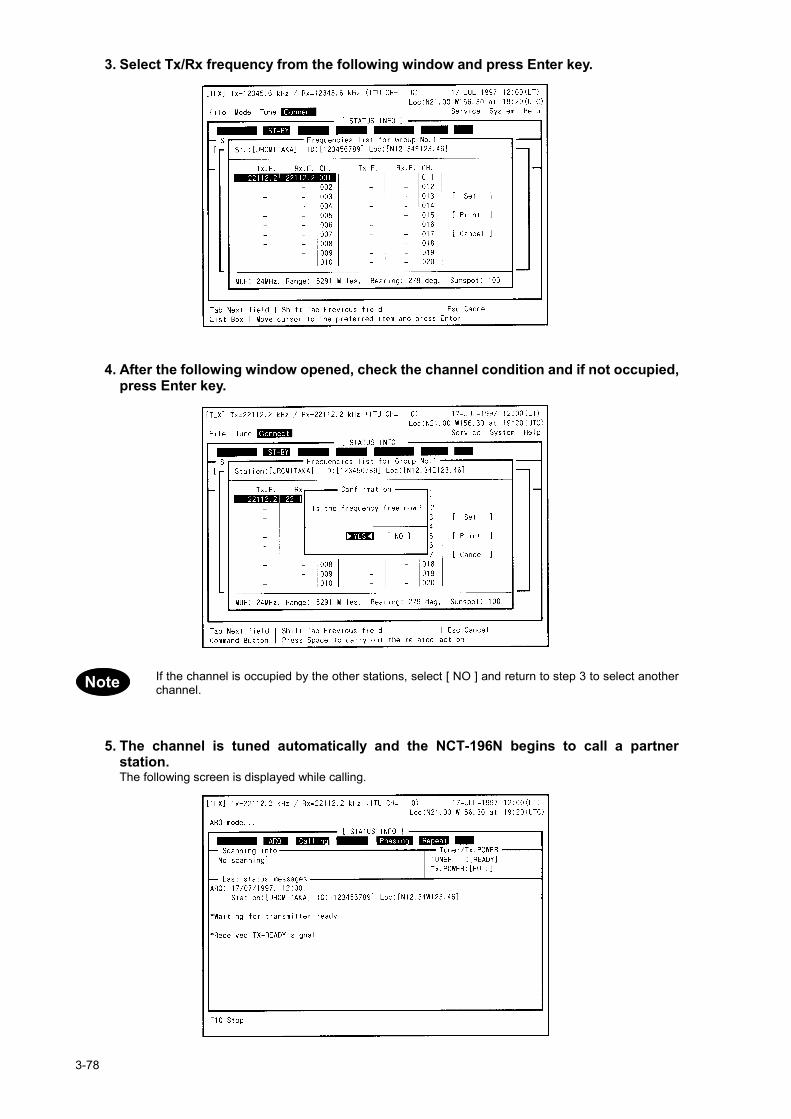
3-78
3. Select Tx/Rx frequency from the following window and press Enter key.
4. After the following window opened, check the channel condition and if not occupied,press Enter key.
If the channel is occupied by the other stations, select [ NO ] and return to step 3 to select anotherchannel.
5. The channel is tuned automatically and the NCT-196N begins to call a partnerstation.The following screen is displayed while calling.
Note

3-79
6. When the connection is established, the following screen appears and the DTE isready to communicate with a partner station.Send message to the partner station using the keyboard.
In case of sending the previously created message file, press F8 (F.Send) and select the file to be senton the following window.
7. To terminate communication, press F10 .The following display appears and the DTE returns to the stand-by.

3-80
The meanings of cells showed in [ STATUS INFO ] are as follows;
(no use) (*1) (*2) (*3) (*4) (*5) (*6)
*1 : Communication mode (stand-by, ARQ, CFEC, SFEC)*2 : The position related with a partner station (Calling - master, Called - slave)*3 : The right to send message (Send - enable to send message, Receive - wait)*4 : MODEM condition on connecting with a partner station (Phasing, Rephasing)*5 : Communication data error condition (Repeat - resending data)*6 : Communication condition (TRAF - sending data completed, RQ - repeating)
The function key F 2 ~ F10 assignments are as follows;
F 2 : WRU - Request to send Answerback code of a partner station F 3 : Here is - Sending Answerback code of own station F 4 : TMS - Sending the time of own position F 5 : Over - Exchanging the right to send message F 6 : POLL - Getting the right to send messages without terminating the
communication even if a partner station try to terminate F 8 : F.Send - Sending the previously created file
F10 : Stop - Terminating communication
Note
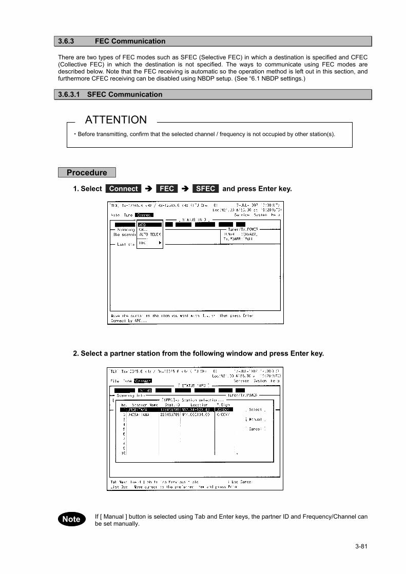
3-81
3.3.6.3 FEC Communication
There are two types of FEC modes such as SFEC (Selective FEC) in which a destination is specified and CFEC(Collective FEC) in which the destination is not specified. The ways to communicate using FEC modes aredescribed below. Note that the FEC receiving is automatic so the operation method is left out in this section, andfurthermore CFEC receiving can be disabled using NBDP setup. (See “6.1 NBDP settings.)
3.6.3.1 SFEC Communication
Procedure
1. Select Connect FEC SFEC and press Enter key.
2. Select a partner station from the following window and press Enter key.
If [ Manual ] button is selected using Tab and Enter keys, the partner ID and Frequency/Channel canbe set manually.
・Before transmitting, confirm that the selected channel / frequency is not occupied by other station(s).
ATTENTION
Note

3-82
3. Select Tx/Rx frequency from the following window and press Enter key.
4. After the following window opened, check the channel condition and if not occupied,press Enter key.
If the channel is occupied by the other stations, select [ NO ] and return to step 3 to select anotherchannel.
5. The channel is tuned automatically and the NCT-196N begins to call a partnerstation. The communication is started after displayed “Message start…” on screen. To terminate communication, press F10 .
Note

3-83
3.6.3.2 CFEC Communication
Procedure
1. Select Connect FEC CFEC and press Enter key.
2. Input Tx/Rx frequency on the following window. Then select [ Set ] using Tab key andpress Enter key.
If input using ITU channel, select [ ITU CHANNEL ] button using Tab and Enter keys.
・Before transmitting, confirm that the selected channel / frequency is not occupied by other station(s).
ATTENTION
Note

3-84
3. After the following window opened, check the channel condition and if not occupied,press Enter key.
If the frequency is occupied by the other stations, select [ NO ] and return to step 2 to select anotherfrequency.
4. The frequency is tuned automatically and the NCT-196N begins to call all ships. The communication is started after displayed “Message start…” on screen. To terminate communication, press F10 .
Note

3-85
3.3.6.4 Scanning for TLX mode
The NBDP function of the NCT-196N can be set to scan a specified group channels so that the NCT-196N respondto the station automatically if there is a station calling own station by ARQ or transmitting by FEC. The way tostart/stop the scanning is described in this section.
3.6.4.1 Scanning start
Procedure
1. Select Tune Scanning start and press Enter key.
2. Select the desired station on the following window and press Enter key.Scanning is started in order by the channel number.
To adjust the intervals for scanning, Select System Scan speed and set scan speed.
↑ ↓ → ←
↑ ↓ → ←
Note

3-86
3.6.4.2 Scanning stop
Procedure
1. Select Tune Scanning stop and press Enter key.
2. Scanning is stopped and the NCT-196N returns to stand-by condition.The Tx/Rx frequency is set to the frequency scanned last.
↑ ↓ → ←

3-87
3.7 PA operations
The NAH-692 Power Amplifier connected to JSB-196GM can be used basically without any settings afterinstallation. However for checking such as output power, voltages or currents or for setting such as alarm orcharge mode, the NAH-692 Power Amplifier has functions as described below.
3.7.1 AC/DC power source voltage checking
Procedure
1. Press Menu button and turn the dial to “AC/DC VOLTAGE” menu on the LCD.
AC,DC VOLTAGE
2. Press ENT button.The menu is selected and LCD shows the AC/DC voltages.
AC Volt 221VDC Volt 24.2V
3. After completed, press Menu button again to return to menu selection.
3.7.2 DC (Battery) charge/discharge current checking
Procedure
1. Press Menu button and turn the dial to “DC CURRENT” menu on the LCD.
DC CURRENT
2. Press ENT button.The menu is selected and LCD shows the value of DC (Battery) charge/ discharge current.
DC CURR +2.5A(- : DISCHG,+ : CHG)
3. After completed, press Menu button again to return to menu selection.

3-88
3.7.3 RF current of Antenna and PA checking
Procedure
1. Press Menu button and turn the dial to “ANT, PA CURR” menu on the LCD.
ANT, PA CURR
2. Press ENT button.The menu is selected and LCD shows the value of Antenna and PA current.
ANT CURR 0.0 APA CURR 0.0 A
3. After completed, press Menu button again to return to menu selection.
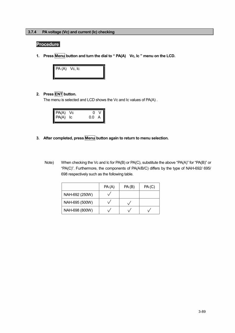
3-89
3.7.4 PA voltage (Vc) and current (Ic) checking
Procedure
1. Press Menu button and turn the dial to “ PA(A) Vc, Ic ” menu on the LCD.
PA (A) Vc, Ic
2. Press ENT button.The menu is selected and LCD shows the Vc and Ic values of PA(A) .
PA(A) Vc 0 VPA(A) Ic 0.0 A
3. After completed, press Menu button again to return to menu selection.
Note) When checking the Vc and Ic for PA(B) or PA(C), substitute the above “PA(A)” for “PA(B)” or“PA(C)”. Furthermore, the components of PA(A/B/C) differs by the type of NAH-692/ 695/698 respectively such as the following table.
PA (A) PA (B) PA (C)
NAH-692 (250W)
NAH-695 (500W)
NAH-698 (800W)

3-90
3.7.5 SWR of PA output checking
Procedure
1. Press Menu button and turn the dial to “PA SWR” menu on the LCD.
PA SWR
2. Press ENT button.The menu is selected and LCD shows the SWR value of PA output.
SWR (A) --.--
3. After completed, press Menu button again to return to menu selection.
Note) When checking the SWR for PA(B) or PA(C), substitute the above “PA(A)” for “PA(B)” or“PA(C)”. Furthermore, the components of PA(A/B/C) differs by the type of NAH-692/ 695/698 respectively such as the following table.
PA (A) PA (B) PA (C)
NAH-692 (250W)
NAH-695 (500W)
NAH-698 (800W)

3-91
3.7.6 Beeping sound ON/OFF setting
Procedure
1. Press Menu button and turn the dial to “TOUCH TONE” menu on the LCD.
TOUCH TONE
2. Press ENT button.The menu is selected and LCD shows setting of TOUCH TONE.
TOUCH TONE ON
3. Turn the dial to select ON or OFF.
TOUCH TONE OFF
4. Press ENT button to set it and return to menu selection.
3.7.7 Alarm sound ON/OFF setting
Procedure
1. Press Menu button and turn the dial to “ALARM TONE” menu on the LCD.
ALARM TONE
2. Press ENT button.The menu is selected and LCD shows setting of ALARM TONE.
ALARM TONE ON
3. Turn the dial to select ON or OFF.
ALARM TONE OFF
4. Press ENT button to set it and return to menu selection.

3-92
3.7.8 Battery charge mode (Ordinary/Equal) setting
Procedure
1. Press Menu button and turn the dial to “CHARGE METHOD” menu on the LCD.
CHARGE METHOD
2. Press ENT button.The menu is selected and LCD shows setting of CHARGE METHOD.
CHARGE METHOD ORDINARY
3. Turn the dial to select ORDINARY or EQUAL.
CHARGE METHOD EQUAL
ORDINARY: Automatic charge mode where the battery is kept fully-charged. This mode isnormally used.
EQUAL: Equaizing charge mode.After setting it as EQUAL mode, when charge current decreased, or when chargetime has passed for 2 hours, it changes to ORDINARY mode automatically.
4. Press ENT button to set it and return to menu selection.
When charge mode changes the EQUAL to the ORDINARY, JSB-196GM may turn off. Inthis case turn on the JSB-196GM.
3.7.9 DC operation
Attention for DC operation1. Single Setting
Either JSB or SES is usable in this setting.・Turn on JSB-196GM : SES is turned off automatically.
(JSB-196GM shows “SES OFF” on LCD.)・Turn off JSB-196GM : SES is turned on automatically after 30-60sec.
2. Dual SettingBoth JSB and SES are simultaneously usable in the setting.
Refer to “Installation manual” about Single/Dual setting.
Note
Note
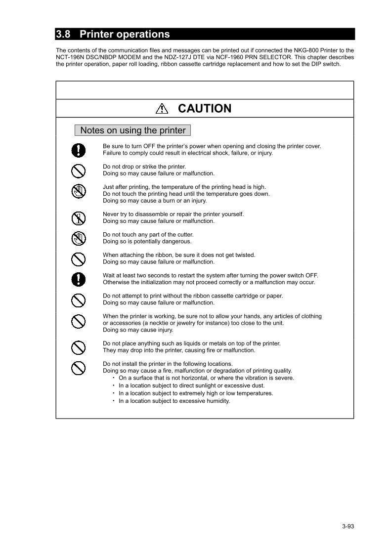
3-93
3.8 Printer operationsThe contents of the communication files and messages can be printed out if connected the NKG-800 Printer to theNCT-196N DSC/NBDP MODEM and the NDZ-127J DTE via NCF-1960 PRN SELECTOR. This chapter describesthe printer operation, paper roll loading, ribbon cassette cartridge replacement and how to set the DIP switch.
CAUTION Notes on using the printer
Be sure to turn OFF the printer’s power when opening and closing the printer cover.Failure to comply could result in electrical shock, failure, or injury.
Do not drop or strike the printer.Doing so may cause failure or malfunction.
Just after printing, the temperature of the printing head is high.Do not touch the printing head until the temperature goes down.Doing so may cause a burn or an injury.
Never try to disassemble or repair the printer yourself.Doing so may cause failure or malfunction.
Do not touch any part of the cutter.Doing so is potentially dangerous.
When attaching the ribbon, be sure it does not get twisted.Doing so may cause failure or malfunction.
Wait at least two seconds to restart the system after turning the power switch OFF.Otherwise the initialization may not proceed correctly or a malfunction may occur.
Do not attempt to print without the ribbon cassette cartridge or paper.Doing so may cause failure or malfunction.
When the printer is working, be sure not to allow your hands, any articles of clothingor accessories (a necktie or jewelry for instance) too close to the unit.Doing so may cause injury.
Do not place anything such as liquids or metals on top of the printer.They may drop into the printer, causing fire or malfunction.
Do not install the printer in the following locations.Doing so may cause a fire, malfunction or degradation of printing quality.・ On a surface that is not horizontal, or where the vibration is severe.・ In a location subject to direct sunlight or excessive dust.・ In a location subject to extremely high or low temperatures.・ In a location subject to excessive humidity.

3-94
3.8.1 Names and Functions
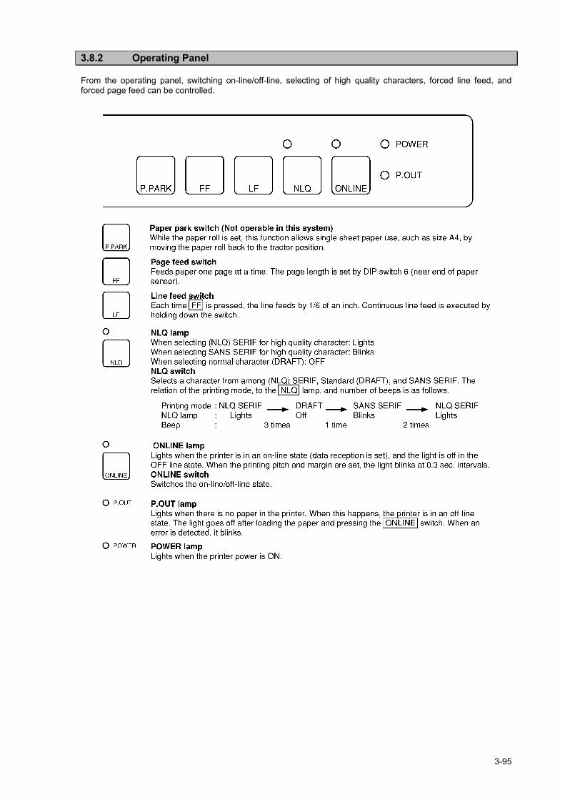
3-95
3.8.2 Operating Panel
From the operating panel, switching on-line/off-line, selecting of high quality characters, forced line feed, andforced page feed can be controlled.

3-96
3.8.3 Opening / Closing the Printer Cover
When opening the printer cover, move the paper roll stand unit one step back. To open/close the printer cover,follow the procedures consecutively.
CAUTIONBe sure to turn OFF the printer's power when opening and closing the printer cover.Failure to comply could result in electrical shock, failure, or injury.
Just after printing, the temperature of the printing head is high. Do not touch theprinting head until the temperature goes down.Failure to comply could result in a burn or injury.
Do not touch any part of the cutter. Doing so is potentially dangerous.
Procedure
1. Loosen the two screws holding the paper roll stand unit fixed.When closing the printer cover, follow the steps in reverse order.
2. Move the paper roll stand unit one step backwards.

3-97
3. Open the printer cover.

3-98
3.8.4 Replacing the Roll Paper
When replacing the paper roll, proceed as follows.
CAUTIONBe sure to turn OFF the printer power when opening and closing the printer cover.Failure to comply could result in electrical shock, failure, or injury.
Just after printing, the temperature of the printer head is high. Do not touch the printer headuntil the temperature goes down.Failure to comply could result in a burn or injury.
Do not touch any part of the cutter. Doing so may result in injury.
Procedure
1. Insert the roll bar through the center of the paper roll.If the leading edge of paper is torn or bent, cut it off in a straight line.
2. Attach the roll bar with the paper roll onto the paper roll stand unit holder, takingcare to notice he paper roll's direction.Set the sensor guide lever so that it touches the paper roll.
・ Perform the consecutive procedures while the printer cover is open.・ To open the printer cover, refer to "9.3 Opening/Closing the Printer Cover".Note

3-99
3. Pull out the leading edge of the paper onto the paper guide bar.
4. Insert the leading edge of the paper from behind the platen
5. Turn the paper feed knob and pull out the leading edge of the paper.

3-100
6. Adjust the paper position for both sides of paper in and paper out, so that the leftand right guide rings of the paper guide bar support the paper lightly.
7. Pull down the reflection lever.The paper touches the platen securely.
8. Pull down the reflection lever.Lift the paper setting lever to harness the paper emerging from the platen.
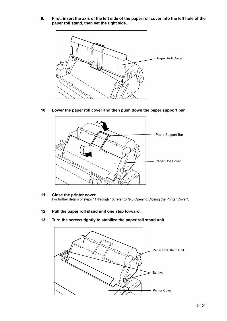
3-101
9. First, insert the axis of the left side of the paper roll cover into the left hole of thepaper roll stand, then set the right side.
10. Lower the paper roll cover and then push down the paper support bar.
11. Close the printer cover.For further details of steps 11 through 13, refer to "9.3 Opening/Closing the Printer Cover".
12. Pull the paper roll stand unit one step forward.
13. Turn the screws tightly to stabilize the paper roll stand unit.

3-102
3.8.5 Replacing the Ribbon Cassette Cartridge
When the printing quality becomes faint, replace the ribbon cassette cartridge with a new one.To replace, proceed as follows.
CAUTIONBe sure to turn OFF the printer power when opening and closing the printer cover.Failure to comply could result in electrical shock, failure, or injury.
Just after printing, the temperature of the printer head is high. Do not touch the printer headuntil the temperature goes down.Failure to comply could result in a burn or injury.
Do not touch any part of the cutter. Doing so may result in injury.
Procedure
1. Open the printer cover.
・ To open the printer cover, refer to "7.3 Opening/Closing the Printer Cover".
2. Lift up the tip of the ribbon cassette cartridge by grasping the projection on top,and remove it.
Note

3-103
3. Turn the cassette knob of the new ribbon cassette cartridge counterclockwise toincrease the tension of the ribbon.
4. Manually, move the printing head to the home position (left side) and place theribbon cassette cartridge in the printer so that the ribbon is positioned betweenthe ribbon mask and the printing head. In this case, make sure that the ribbon feedaxis is inserted through the hole under the ribbon cassette knob.
・ Lightly press the ribbon cassette cartridge at both ends.・ Turn the cassette knob again to increase the tension of the ribbon.・ Confirm that the ribbon is positioned properly in front of the printing head.
5. Close the printer cover
Note

3-104
3.8.6 Adjusting the Printing Pressure (to Printing Paper Thickness)
The printing pressure can be adjusted with the head adjust lever located on the right side of the inner part of theprinter.
CAUTIONBe sure to turn OFF the printer power when opening and closing the printer cover.Failure to comply could result in electrical shock, failure, or injury.
Just after printing, the temperature of the printer head is high. Do not touch the printer headuntil the temperature goes down.Failure to comply could result in a burn or injury.
Do not touch any part of the cutter. Doing so may result in injury.
Procedure
1. Open the printer cover and set up the head adjusting lever.Each type of paper should be set as follows:
Normal paper : The optimal position among the numbers shown is .Three layers of copying paper : The optimum position is or .
・ The printing pressure increases in numerical order ( → ).・ To open/close the printer cover, refer to "7.3 Opening/Closing the Printer Cover".
Note

3-105
3.8.7 Setting the DIP Switch
Set the DIP switch to select a language, character set, or particular function.
ATTENTIONBefore beginning the procedure, be sure to turn the power OFF.Failure to do so may cause electrical shock, malfunction or injury.
Just after printing, the temperature of the printer head is high. Do not touch the printer headuntil the temperature goes down.Doing so may cause burns or injury.
Do not touch any part of the cutter.Doing so is potentially dangerous and may cause injury.
Procedure
1. Open the printer cover, remove the ribbon cassette cartridge, and move theprinting head manually to the right end.
・ The printing pressure increases in numerical order ( → ).・ To open/close the printer cover, refer to "7.3 Opening/Closing the Printer Cover".・ To remove the ribbon cassette cartridge, refer to "7.5 Replacing the Ribbon Cassette Cartridge".
2. Hold the tip of the partition cover and slide it to the left to remove it.The DIP switch appears.
Note

3-106
3. Set the DIP switch to desired modeThe following diagrams describe the relation between each DIP switch position and the content of eachsetting.
4. When settings are completed, put the partition cover back in its place, set up theribbon cassette, and then close the printer cover.
5. While pressing NLQ turn the power ON.After initialization is carried out, the selected function and current setting status of the DIP switch areprinted.
・ When printing under the current setting status, the printer is set to an off-line state. When the testpattern is completely printed out, it is automatically set to an on-line state.Note

3-107
Dip switch setting for each equipment.
DIP switch setting
JSS-296(NCT-196N/NDZ-127J)JSS-825D(NCT-620D)
NCT-196NCT-196N
JSS-850JUE-75C(NDZ-127C)
JSS-825NA/NC(NDZ-127N)
3.8.8 How to Attend to Error Detection
There are two types of errors. When an error is detected, a beep sounds, and the P.OUT lamp blinks 5 times.
(1) Paper discharge errorWhen the "out of paper" state is not detected, even though an 18 inch line feed procedure is performed, a paperdischarge error will result. The P.OUT lamp remains blinking until the error state is canceled.When this happens, manually pull the paper out of the printer, or remove the paper automatically by using LF orFF , then press ONLINE .
(2) Paper sending errorIf the paper is not properly set, even though a 10 inch line feed procedure is performed, a paper sending errorresults. In addition, if this error happens when the printing instruction is entered, the P.OUT lamp remains blinkinguntil the error state is canceled.
When this happens, follow the procedure below.
Procedure
1. Press ONLINE switch.The printer is set to an off-line state.
2. Press FF switch, set the paper, then press ONLINE .The printer is set to an on-line state.
1 2 3 4 5 6 7 8OFF
ONDIP switch
1 2 3 4 5 6 7 8OFF
ONDIP switch
1 2 3 4 5 6 7 8OFF
ONDIP switch
Note

3-108

4-1
4. MAINTENANCE AND INSPECTION
The performance and longevity of this equipment depend on careful maintenance. To maintain the bestperformance, the following periodic inspections are highly recommended.
(1) Keep the power supply voltage within the specified value.(2) Know the condition of normal status when the equipment is properly functioning. Keep comparing the
current status to the normal status to immediately detect any malfunctions.
WARNINGIf you remove a unit, be sure to store it in a non-conductive bag. If you wrap It up with materials such as aluminum foil, the back-up power supply may Short circuit and the ICs may be damaged.
There are no user-serviceable parts inside this equipment. Inspection or maintenance by unauthorized persons may result in fire or electric shock.For inspection and maintenance, contact JRC or its authorized agents.
CAUTIONDo not turn the trimmer resistors or trimmer capacitors on the PCB unit (they are presetat the factory). Doing so may cause failure or malfunction.
Leave installation of this equipment to JRC or our agents. Installation by anunauthorized person may lead to malfunction.
This chapter describes about the JSS-296 Radio Equipment as a whole. So if further informationis required, see the specialized instruction manuals such as the JSB-196GM Radiotelephone or NCT-196NDSC/NBDP MODEM.
ATTENTION
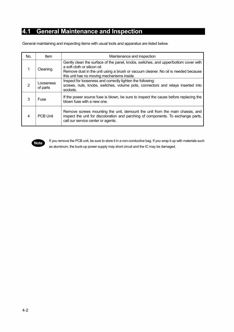
4-2
4.1 General Maintenance and Inspection
General maintaining and inspecting items with usual tools and apparatus are listed below.
No. Item Maintenance and inspection
1 Cleaning
Gently clean the surface of the panel, knobs, switches, and upper/bottom cover witha soft cloth or silicon oil.Remove dust in the unit using a brush or vacuum cleaner. No oil is needed becausethis unit has no moving mechanisms inside.
2 Loosenessof parts
Inspect for looseness and correctly tighten the following:screws, nuts, knobs, switches, volume pots, connectors and relays inserted intosockets.
3 Fuse If the power source fuse is blown, be sure to inspect the cause before replacing theblown fuse with a new one.
4 PCB UnitRemove screws mounting the unit, demount the unit from the main chassis, andinspect the unit for discoloration and parching of components. To exchange parts,call our service center or agents.
If you remove the PCB unit, be sure to store it in a non-conductive bag. If you wrap it up with materials suchas aluminum, the buck-up power supply may short circuit and the IC may be damaged.
Note

5-1
5. AFTER-SALES SERVICE
5.1 Before returning repair
If what appears to be a defect is detected, refer to Troubleshooting descriptions of the specialized instructionmanual for every unit to check if the equipment is actually defective before requesting repair.If the defect persists, immediately stop operation and call our service center or agents.
During the warranty period, we or our agencies (*1) will repair the malfunction without any fee,according to the specified procedure.After the warranty expires, we will repair the malfunction for a fee, if repair is possible.Items for notification- Product name, type, manufactured data, serial number,- information about the malfunction (the more detailed, the better),- your company or organization name, address and phone number.
(*1) Refer to the inside of the back cover for contact numbers.
5.2 Periodical maintenance recommended
Performance of this equipment may degrade over time because parts wear out, although degradation dependson how this unit has been maintained, thus we recommend periodic professional maintenance checks inaddition to daily maintenance. So please contact our service center or agents for periodic professionalmaintenance (This maintenance requires a service charge), or for further information about after-sales service.

5-2

6-1
6. SPECIFICATIONS
1. GENERAL
Frequency range: Transmit: 1.6 to 27.5MHz (100Hz steps)Receive: 0.1 to 29.9999MHz (100Hz steps)
Frequency tolerance: ±10Hz or betterEmission mode: J3E (TEL), F1B (DSC/TLX), A1A (CW), H2B,
H3E (AME: reception only)User definable channels: 200ch (20ch X 10 Groups)Preset ITU channels: 1722ch [ TEL:283, DSC:29, TLX:891, CW:519 ]Scanning channel 20 user defined channelsCommunication mode: Simplex and semi-duplexAntenna impedance:Operating temperature:Power requirement:
50 ohms-15 to +55oC90~132V/180~264V AC, Single-phase, 50/60HzTx: 2.0kVA max, Rx: 0.5kVA max21.6~31.2V DCTx: 30A max, Rx: 7A max
Compass safe distance: 1.5m
2. TRANSMITTER
Output power: AC power source:200Wpx ( 1.6 to 4MHz ) , 250Wpx ( 4 to 27.5MHz )DC power source:100Wpx ( 1.6 to 4MHz ) , 150Wpx ( 4 to 27.5MHz )
Occupied bandwidth: J3E (TEL) 3kHz or betterF1B (DSC/TLX), A1A (CW) 0.5kHz or better
Carrier suppression: 40dB or betterSpurious suppression: 43dB or betterAF frequency response: 350 to 2700Hz (6dB bandwidth)Microphone input: 600 ohms (-40dBm standard)Line input: 600 ohms, 0dBm (balanced)

6-2
3. RECEIVER
Receiving system: Triple superheterodyneIntermediate frequencies: 70.455MHz, 455kHz, 20.217kHzSensitivity (SINAD 20dB): J3E (TEL) 6.3uV or better (1.6 to 4MHz)
3.5uV or better (4 to 27.5MHz)F1B (DSC/TLX) 1.8uV or better (1.6 to 4MHz)
1.0uV or better (4 to 27.5MHz)Selectivity: J3E (TEL) 6dB bandwidth 2.4 to 3kHz,
66dB bandwidth Within ±2.1kHzF1B (DSC/TLX) 6dB bandwidth 270 to 300Hz,
60dB bandwidth Within ±550HzSpurious response: 60dB or betterClarifier range: ±200Hz in 1Hz stepsAF output: 5.0W max. 1W ratedLine output: 600 ohms, 0dBm (balanced)
4. DSC/NBDP TERMINAL
DSC MODEMCommunications protocol: In conformity with ITU-RM.493 and M.541Emission: F1B/J2B 100 baudCode: 10 units error detection specified by ITU-RM.493.Memory capacity: Received Distress messages: 20
Received Other messages: 20Transmitted message: 11
Clock: Within +/- 30ppm
Data backup time: 24 hours (message content and time data)Mark frequency: 1615 +/- 0.5HzSpace frequency: 1785 +/- 0.5HzOutput level: 0dBm (-20 to +10dBm variable/600 ohms balanced)Input frequency : 1700 +/- 85HzInput level : -25 to +10dBm (600-ohm balanced load)
NBDP MODEMCommunications protocol: In conformity with ITU-RM.476, M.490, M.491, M.492, M.625
and ITU-T Rec. F130Emission: F1B/J2B 100 baudCode: 7-bit code 4B/3Y ratio constant mark signalClock: Within +/- 30ppmMark frequency: 1615 +/- 0.5Hz
Space frequency: 1785 +/- 0.5HzOutput level: 0dBm (-20 to +10dBm variable/600 ohms balanced)Input frequency : 1700 +/- 85HzInput level : -25 to +10dBm (600-ohm balanced load)

6-3
5. WATCHKEEPING RECEIVER
Receiving frequencies: 2187.5kHz、4207.5kHz、6312kHz、8414.5kHz、12577kHz、16804.5kHz
Receiving system: Double superheterodyneIntermediate frequencies: 40.455MHz, 455kHzReception mode: F1B/J2BSensitivity: Symbol error rate of 1% or better at 1 micro-volt inputFrequency stability: Within +/- 10Hz after 1-minute warm-up
Antenna impedance: 50 ohms unbalanced
6. ANTENNA TUNER
Frequency range: 1.6 to 30MHzPower capability: 300WpxSWR after tuning: 2:1Tuning method: Automatic tuning and preset tuningTuning time: Automatic tuning: typical 3sec
Preset tuning: typical 0.5secOperating temperature: -25 to +55 oC
7. BATTERY CHARGER
Charging current: 20A (Ordinary charge)10A (Equalizing charge)
Alarm function: Charge /Low voltage/ High voltage alarm
8. DATA TERMINAL
Controlled item: NBDP function (Control the DSC/NBDP Terminal)
9. KEYBOARD
Interface: MatrixContact method: Membrane sheetLife: 5 million strokes
10. PRINTER
Print method: Serial impact dot matrixInterface: CentronicsPaper feed method: Paper roll holderPaper type: 209 to 216mm Roll paper


JSS-296MF/HF RADIO EQUIPMENT
INSTRUCTIONMANUAL
Nittochi Nishi-Shinjuku bldg.10-1, Nishi-Shinjuku 6-chome, Shinjuku-ku, Tokyo 160-8328 JAPANPhone : +81-3-3348-0151Fax : +81-3-3348-3648
1-1, Shimorenjaku 5-chome, Mitaka-shi, Tokyo 181-8510 JAPANPhone : +81-422-45-9111Fax : +81-422-45-9110
HEAD OFFICE & SALES DEPT.
MAIN PLANT
For further information contact:
Since 1915
CODE NO. 7ZPJD0162 JRC
EDITION 2 JAN. 2003
MF
/HF
RA
DIO
EQ
UIP
ME
NT
INS
TR
UC
TIO
N M
AN
UA
LJS
S-296


