doc.: IEEE 802.15-15-13-0358-00-0thz <July 2013> Project: IEEE P802.15 Working Group for Wireless Personal Area Networks (WPANs) Project: IEEE P802.15 Working Group for Wireless Personal Area Networks (WPANs) Submission Title: A Stochastic Indoor Radio Channel Model for THz WPANs/WLANs Date Submitted: 11 July, 2013 Source: Sebastian Priebe, Technische Universität Braunschweig Address: Schleinitzstraße 22, D-38106 Braunschweig, Germany Voice: +49-531-391-2417, FAX: +49-531-391-5192, E-Mail: [email protected]Abstract: Building upon the experimental understanding of the THz indoor radio channel and a deterministic ray tracing propagation simulator , a stochastic channel modeling approach is proposed. Such a model becomes inevitable for the system conception of THz WPANs or WLANs as soon as a system design is developed based on system simulations. Then, realistic channel conditions must be respected. For this purpose, the model features broadband channel realizations with 50 GHz bandwidth, is fully polarimetric, includes spatial channel information and allows for the fast generation of channel realizations. Re: 15-10-0436-01-0thz_Towards_a_300_GHz_Channel_Model.pdf Purpose: Foundation document for a THz WPAN/WLAN channel model Notice: This document has been prepared to assist the IEEE P802.15. It is offered as a basis for discussion and is not binding on the contributing individual(s) or organization(s). The material in this document is subject to change in form and content after further study. The contributor(s) reserve(s) the right to add, amend or withdraw material contained herein. Submission Release: The contributor acknowledges and accepts that this contribution becomes the property of IEEE and may be made publicly available by P802.15. Slide 1 Sebastian Priebe, TU Braunschweig
Transcript
doc.: IEEE 802.15-15-13-0358-00-0thz<July 2013>
Project: IEEE P802.15 Working Group for Wireless Personal Area Networks (WPANs)Project: IEEE P802.15 Working Group for Wireless Personal Area Networks (WPANs)
Submission Title: A Stochastic Indoor Radio Channel Model for THz WPANs/WLANsDate Submitted: 11 July, 2013Source: Sebastian Priebe, Technische Universität BraunschweigAddress: Schleinitzstraße 22, D-38106 Braunschweig, GermanyVoice: +49-531-391-2417, FAX: +49-531-391-5192, E-Mail: [email protected]: Building upon the experimental understanding of the THz indoor radio channel and adeterministic ray tracing propagation simulator, a stochastic channel modeling approach is proposed. Suchy g p p g , g pp p pa model becomes inevitable for the system conception of THz WPANs or WLANs as soon as a systemdesign is developed based on system simulations. Then, realistic channel conditions must be respected. Forthis purpose, the model features broadband channel realizations with 50 GHz bandwidth, is fullypolarimetric, includes spatial channel information and allows for the fast generation of channel realizations.p , p g
Purpose: Foundation document for a THz WPAN/WLAN channel model
Notice: This document has been prepared to assist the IEEE P802.15. It is offered as a basis fordiscussion and is not binding on the contributing individual(s) or organization(s). The material in thisdocument is subject to change in form and content after further study. The contributor(s) reserve(s) the rightto add, amend or withdraw material contained herein.
Submission
Release: The contributor acknowledges and accepts that this contribution becomes the property of IEEE and may be made publicly available by P802.15.
Slide 1 Sebastian Priebe, TU Braunschweig
doc.: IEEE 802.15-15-13-0358-00-0thz<July 2013>
A Stochastic Indoor Radio Channel Model for THz WPANs/WLANs
Sebastian Priebe1, Thomas Kürner1
1 Institut für Nachrichtentechnik, Technische Universität Braunschweig, Germany
Submission Sebastian Priebe, TU BraunschweigSlide 2
doc.: IEEE 802.15-15-13-0358-00-0thz<July 2013>
Outline
1. Introduction2. Modeling Conceptg p3. The THz Indoor Radio Channel Model4. Validation5. Summary/Outlook
Submission Sebastian Priebe, TU BraunschweigSlide 3
doc.: IEEE 802.15-15-13-0358-00-0thz
Introduction (1)<July 2013>
1. Preliminary work: indoor radio channel measurementsB d t t k l
Introduction (1)
– Based on a vector network analyzer– Rotation of TX and RX in the azimuth: 360 x 360°– Automatic setup
°
Measurement parameter Value
TX
RX
Frequency 275 - 325 GHzAngular resolution 2°Dynamic range 145 dBMeasurement duration forone position (360° x 360°)
90 h
Submission Sebastian Priebe, TU BraunschweigSlide 4
doc.: IEEE 802.15-15-13-0358-00-0thz
Introduction (2)<July 2013>
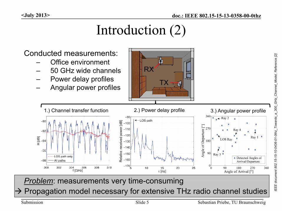
Conducted measurements:Offi i t
Introduction (2)
ce [2
]
– Office environment– 50 GHz wide channels– Power delay profiles– Angular power profiles
RX
TX
nnel
_Mod
el, R
efer
enc
g p p
rds_
a_30
0_G
Hz_
Cha
1.) Channel transfer function 2.) Power delay profile 3.) Angular power profile
0-04
36-0
1-0t
hz_T
owar
Problem: measurements very time consuming ocum
ent8
02.1
5-15
-10
Submission
Propagation model necessary for extensive THz radio channel studiesProblem: measurements very time-consuming
Sebastian Priebe, TU BraunschweigSlide 5
IEE
E d
o
doc.: IEEE 802.15-15-13-0358-00-0thz
Introduction (3)<July 2013>
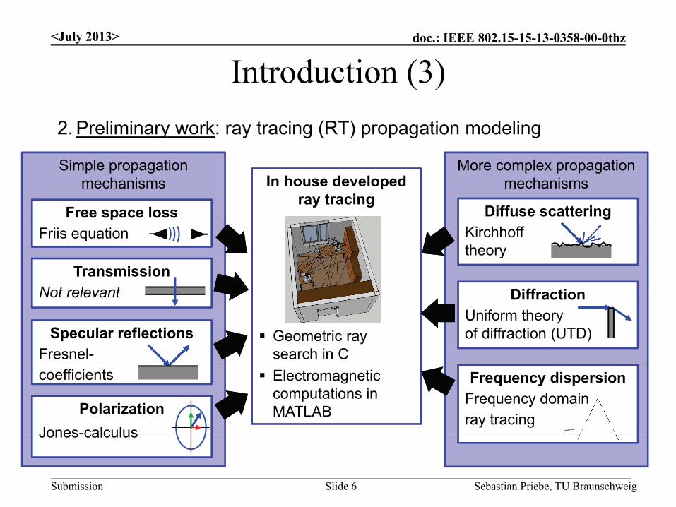
2. Preliminary work: ray tracing (RT) propagation modeling
Introduction (3)
More complex propagationmechanisms
Simple propagationmechanisms
Diffuse scattering
In house developedray tracing
Free space loss gKirchhofftheory
Diff tiTransmission
Not relevant
Free space lossFriis equation
Geometric raysearch in C
DiffractionUniform theoryof diffraction (UTD)
Not relevant
Specular reflectionsFresnel-
Electromagneticcomputations in MATLAB
Frequency dispersionFrequency domainray tracing
coefficients
PolarizationJones-calculus
Submission Sebastian Priebe, TU BraunschweigSlide 6
Jones calculus
doc.: IEEE 802.15-15-13-0358-00-0thz
Introduction (4)<July 2013>
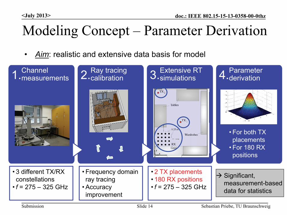
• Idea: optimize material parameters for RT V lid ti d lib ti f th RT t l b d t
Introduction (4)
Validation and calibration of the RT tool based on measurements
Difference between measured andsimulated ray powers
Submission Sebastian Priebe, TU BraunschweigSlide 14
• f = 275 – 325 GHz • Accuracyimprovement
• f = 275 – 325 GHz measurement based data for statistics
doc.: IEEE 802.15-15-13-0358-00-0thz<July 2013>
Outline
1. Introduction2. Modeling Conceptg p3. The THz Indoor Radio Channel Model
• Number of Rays• Times of Arrival• Amplitudes• …
4. Validation
Submission Sebastian Priebe, TU BraunschweigSlide 15
5. Summary/Outlook
doc.: IEEE 802.15-15-13-0358-00-0thz
THz Channel Model Number of Rays<July 2013>
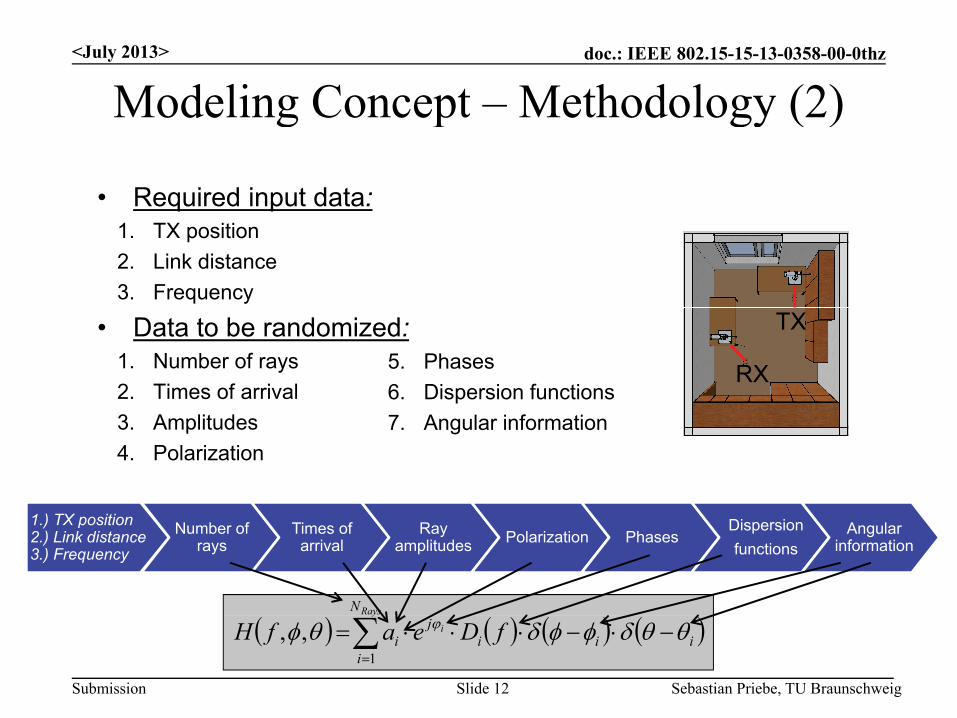
S t di d i i
THz Channel Model – Number of Rays1.) TX position2.) Link distance3.) Frequency
Number ofrays
Times ofarrival
Ray amplitudes Polarization Phases
Dispersionfunctions
Angular information
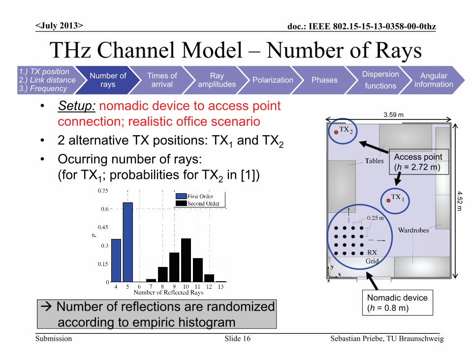
• Setup: nomadic device to access pointconnection; realistic office scenario
• 2 alternative TX positions: TX1 and TX2
3.59 m
• Ocurring number of rays:(for TX1; probabilities for TX2 in [1])
4.52
Access point(h = 2.72 m)
2 m
N b f fl ti d i dNomadic device
Submission
Number of reflections are randomizedaccording to empiric histogram
Sebastian Priebe, TU BraunschweigSlide 16
(h = 0.8 m)
doc.: IEEE 802.15-15-13-0358-00-0thz
THz Channel Model Times of Arrival<July 2013>
THz Channel Model – Times of Arrival1.) TX position2.) Link distance3.) Frequency
Number ofrays
Times ofarrival
Ray amplitudes Polarization Phases
Dispersionfunctions
Angular information
• Analytic arrival time of the line-of-sight (LOS) ray: ith ray
• Recursive time of arrival (ToA) of the ith ray withrespect to the previous path:
• Histogram of the occuring relative ToAs: Approximation with negative exponential Approximation with negative exponential
distribution (parameters in [1])
Recursive randomization of the ToAs
Submission Sebastian Priebe, TU BraunschweigSlide 17
Different treatment of the first arriving rays (omitted here) [1]
doc.: IEEE 802.15-15-13-0358-00-0thz
THz Channel Model Amplitudes (1)<July 2013>
THz Channel Model – Amplitudes (1)1.) TX position2.) Link distance3.) Frequency
Number ofrays
Times ofarrival
Ray amplitudes Polarization Phases
Dispersionfunctions
Angular information
• LOS amplitude: analytical dependent on distance (f0 = 300 GHz)
• Example: power delay profile for connectionTX1/RX1
Only up to second order rays relevant because of high losses
Submission
Only up to second order rays relevant because of high losses Amplitude modeling with random logarithmic-linear decay over time
Sebastian Priebe, TU BraunschweigSlide 18
doc.: IEEE 802.15-15-13-0358-00-0thz
THz Channel Model Amplitudes (2)<July 2013>
THz Channel Model – Amplitudes (2)1.) TX position2.) Link distance3.) Frequency
Number ofrays
Times ofarrival
Ray amplitudes Polarization Phases
Dispersionfunctions
Angular information
• Delay-amplitude function for the reflected rays:
D i ti ith th d t
Histrograms forthe three
• Description with three random parameters:
the threeparametersrequired
Submission Sebastian Priebe, TU BraunschweigSlide 19
Amplitudes assignable based on ToAs of the rays
doc.: IEEE 802.15-15-13-0358-00-0thz
THz Channel Model Amplitudes (3)<July 2013>
THz Channel Model – Amplitudes (3)1.) TX position2.) Link distance3.) Frequency
Number ofrays
Times ofarrival
Ray amplitudes Polarization Phases
Dispersionfunctions
Angular information
• Derivation of histograms for the delay-amplitude parameters:
Consideration of 180 RX positionsp Approximation of the empirical
histograms with analytical PDFs (parameters in [1])(p [ ])
Submission Sebastian Priebe, TU BraunschweigSlide 20
doc.: IEEE 802.15-15-13-0358-00-0thz
THz Channel Model Polarization<July 2013>
THz Channel Model – Polarization1.) TX position2.) Link distance3.) Frequency
Number ofrays
Times ofarrival
Ray amplitudes Polarization Phases
Dispersionfunctions
Angular information
• So far: randomized amplitudes contain co and cross polarization
Decomposition into co and cross components via random cross polarization discrimination (XPD)
Submission Sebastian Priebe, TU BraunschweigSlide 21
doc.: IEEE 802.15-15-13-0358-00-0thz
THz Channel Model Phases<July 2013>
THz Channel Model – Phases1.) TX position2.) Link distance3.) Frequency
Number ofrays
Times ofarrival
Ray amplitudes Polarization Phases
Dispersionfunctions
Angular information
• Analytic phase of the LOS ray:
• Phase histogram of all reflected rays:
Submission Sebastian Priebe, TU BraunschweigSlide 22
Randomization of the phases according to a uniform distribution
doc.: IEEE 802.15-15-13-0358-00-0thz
THz Channel Model Dispersion Functions (1)<July 2013>
THz Channel Model – Dispersion Functions (1)1.) TX position2.) Link distance3.) Frequency
Number ofrays
Times ofarrival
Ray amplitudes Polarization Phases
Dispersionfunctions
Angular information
• Carrier frequency f0 = 300 GHz• Huge bandwidths up to 50 GHz CTFs become dispersive
Example: CTF for a LOS link, d = 5.3 m CTFs become dispersive
Introduction of a frequency-dependentdispersion function necessary
1.4 dB
Rays
i
N
iiii
ji fDeafH
1,,
300 GHz300 GHz
Ray-specificdispersion
Submission Sebastian Priebe, TU BraunschweigSlide 23
dispersioncoefficient
doc.: IEEE 802.15-15-13-0358-00-0thz
THz Channel Model Dispersion Functions (2)<July 2013>
THz Channel Model – Dispersion Functions (2)1.) TX position2.) Link distance3.) Frequency
Number ofrays
Times ofarrival
Ray amplitudes Polarization Phases
Dispersionfunctions
Angular information
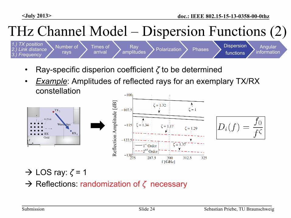
• Ray-specific disperion coefficient ζ to be determined• Example: Amplitudes of reflected rays for an exemplary TX/RX
constellationconstellation
plitu
de [d
B]
Ref
lect
ion
Am
p
LOS ray: ζ = 1 Reflections: randomization of ζ necessary
R
Submission Sebastian Priebe, TU BraunschweigSlide 24
ζ y
doc.: IEEE 802.15-15-13-0358-00-0thz
THz Channel Model Dispersion Functions (3)<July 2013>
THz Channel Model – Dispersion Functions (3)1.) TX position2.) Link distance3.) Frequency
Number ofrays
Times ofarrival
Ray amplitudes Polarization Phases
Dispersionfunctions
Angular information
• Empiric cumulative distribution functions (CDFs) of the occuring ζ(TX1, 180 RX positions, f = 275 - 325 GHz)
Eachreflection atthe 180 RX positionspositions
Approximation with linear polynomials (parameters a and b in [1]) Randomization of the dispersion functions possible
Submission Sebastian Priebe, TU BraunschweigSlide 25
p p
doc.: IEEE 802.15-15-13-0358-00-0thz
THz Channel Model Angular Information (1)<July 2013>
THz Channel Model – Angular Information (1)1.) TX position2.) Link distance3.) Frequency
Number ofrays
Times ofarrival
Ray amplitudes Polarization Phases
Dispersionfunctions
Angular information
• Spatial information obligatory for simulationsincluding antennas
• Joint modeling of the AoAs/AoDs required forJoint modeling of the AoAs/AoDs required forrealistic channels
• AoAs/AoDs dependent on random RX placement Randomization of angles in the AoA/AoD domain Randomization of angles in the AoA/AoD domain
Histogram ofoccurring angles in the AoA/AoD domain:
Rays depart/arriveonly within a fewlimited angular ranges
the AoA/AoD domain:
Submission Sebastian Priebe, TU BraunschweigSlide 26
limited angular ranges
doc.: IEEE 802.15-15-13-0358-00-0thz
THz Channel Model Angular Information (2)<July 2013>
THz Channel Model – Angular Information (2)1.) TX position2.) Link distance3.) Frequency
Number ofrays
Times ofarrival
Ray amplitudes Polarization Phases
Dispersionfunctions
Angular information
(a) Azimuth modeling1. LOS path: random RX placement in horizontal plane uniform Φ distribution between [0°; 360°] uniform ΦAoA,LOS distribution between [0 ; 360 ]
2. Reflections:– Angular ranges defined through line segments in
the AoA/AoD domainthe AoA/AoD domain
Submission Sebastian Priebe, TU BraunschweigSlide 27
doc.: IEEE 802.15-15-13-0358-00-0thz
THz Channel Model Angular Information (3)<July 2013>
THz Channel Model – Angular Information (3)1.) TX position2.) Link distance3.) Frequency
Number ofrays
Times ofarrival
Ray amplitudes Polarization Phases
Dispersionfunctions
Angular information
• Line segments in the AoA/AoD domain defined through start andstop points ,
• Gaussian distributions of occurring angles along the line segments:Gaussian distributions of occurring angles along the line segments:
Randomization ofthe azimuth AoAsthe azimuth AoAsfrom the GaussianPDFs (parametersin [1])
• Gaussian PDF parameters:
[ ])
Submission Sebastian Priebe, TU BraunschweigSlide 28
p
doc.: IEEE 802.15-15-13-0358-00-0thz
THz Channel Model Angular Information (4)<July 2013>
THz Channel Model – Angular Information (4)1.) TX position2.) Link distance3.) Frequency
Number ofrays
Times ofarrival
Ray amplitudes Polarization Phases
Dispersionfunctions
Angular information
• Azimuth AoAs randomizable Determination of the azimuth AoDs from the AoAs:
• Analytic expressions:
Azimuth AoDsfrom the analytic
Submission Sebastian Priebe, TU BraunschweigSlide 29Multiples of 180° (cf. [1])
dependencies
doc.: IEEE 802.15-15-13-0358-00-0thz
THz Channel Model Angular Information (5)<July 2013>
THz Channel Model – Angular Information (5)1.) TX position2.) Link distance3.) Frequency
Number ofrays
Times ofarrival
Ray amplitudes Polarization Phases
Dispersionfunctions
Angular information
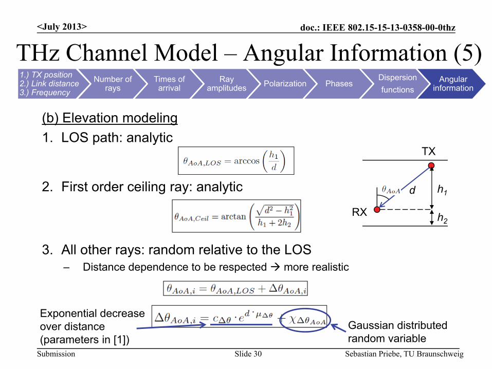
(b) Elevation modeling1. LOS path: analytic
TX
2. First order ceiling ray: analytic
RX
h1d
3. All other rays: random relative to the LOSDi t d d t b t d li ti
RX h2
– Distance dependence to be respected more realistic
Exponential decrease
Submission Sebastian Priebe, TU BraunschweigSlide 30
Gaussian distributedrandom variable
Exponential decreaseover distance(parameters in [1])
doc.: IEEE 802.15-15-13-0358-00-0thz
THz Channel Model Angular Information (6)<July 2013>
THz Channel Model – Angular Information (6)1.) TX position2.) Link distance3.) Frequency
Number ofrays
Times ofarrival
Ray amplitudes Polarization Phases
Dispersionfunctions
Angular information
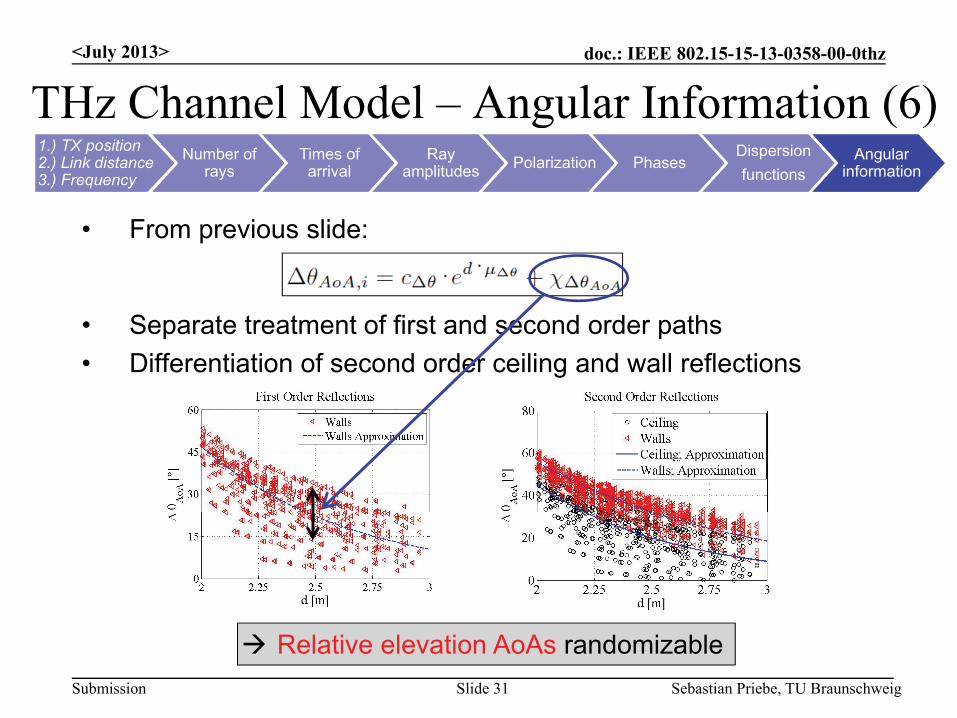
• From previous slide:
• Separate treatment of first and second order paths• Differentiation of second order ceiling and wall reflections
Submission Sebastian Priebe, TU BraunschweigSlide 31
Relative elevation AoAs randomizable
doc.: IEEE 802.15-15-13-0358-00-0thz
THz Channel Model Angular Information (7)<July 2013>
THz Channel Model – Angular Information (7)1.) TX position2.) Link distance3.) Frequency
Number ofrays
Times ofarrival
Ray amplitudes Polarization Phases
Dispersionfunctions
Angular information
• Determination of the elevation AoD from the AoA:1. LOS path:
2. First order ceiling:
3 Others:
Linear behavior over
3. Others:
Gaussian distributedrandom variable
distance (parameters in [1])
Submission Sebastian Priebe, TU BraunschweigSlide 32
Complete determination of all angles possible
doc.: IEEE 802.15-15-13-0358-00-0thz
THz Channel Model Realization Generation<July 2013>
THz Channel Model – Realization Generation1.) TX position2.) Link distance3.) Frequency
Number ofrays
Times ofarrival
Ray amplitudes Polarization Phases
Dispersionfunctions
Angular information
1. Define TX position, specify link distance, give frequency range2. Randomize number of reflected rays (first and second order)3 Determine ToAs (LOS analytic reflections recursive)3. Determine ToAs (LOS analytic, reflections recursive)4. Obtain parameters of ToA-amplitude funtions and determine
amplitudes5 Separate polarization components via random cross5. Separate polarization components via random cross
polarization discriminations6. Assign uniformly distributed phases to the rays
ff f7. Determine dispersion coefficients from empiric distributions8. Randomize AoAs/AoDs in the azimuth/elevation
C
Submission Sebastian Priebe, TU BraunschweigSlide 33
Complete channel realization
doc.: IEEE 802.15-15-13-0358-00-0thz<July 2013>
Outline
1. Introduction2. Modeling Conceptg p3. The THz Indoor Radio Channel Model4. Validation
• Broadband Channel Properties• Spatial Characteristics• MIMO Capabilities• Model Limitations/Advantages
Submission Sebastian Priebe, TU BraunschweigSlide 34
5. Summary/Outlook
doc.: IEEE 802.15-15-13-0358-00-0thz
Validation Broadband Channel PropertiesValidation – Broadband Channel Properties• Idea: validation of the stochastic model against RT simulations• Methodology: RT simulations for 180 RX placements vs. 1000
stochastic realizations each, 275 – 325 GHz• Comparison of the resulting Rician k factors
(measure for the multipath richness of a channel):
180 RX positions,1000 realizations each
Similar curves regardless of TX position
Submission
Similar curves regardless of TX position Randomization of realistic multipath powers
Sebastian Priebe, TU BraunschweigSlide 35
doc.: IEEE 802.15-15-13-0358-00-0thz
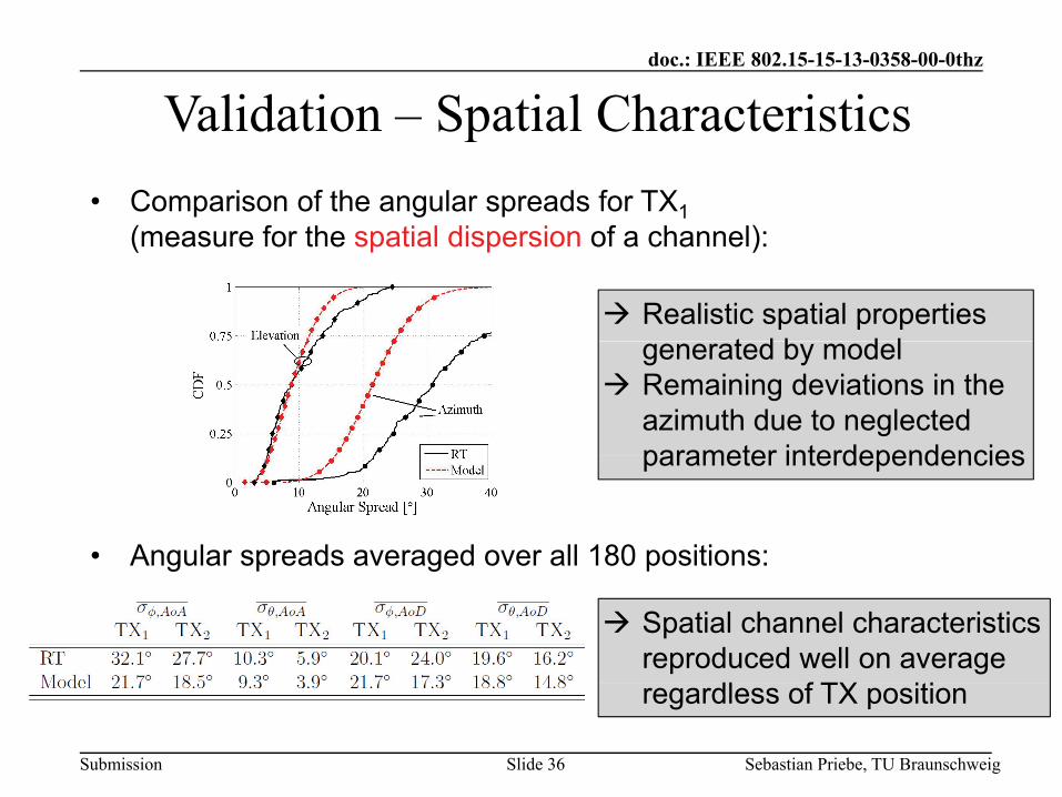
Validation Spatial Characteristics• Comparison of the angular spreads for TX1
( f th ti l di i f h l)
Validation – Spatial Characteristics
(measure for the spatial dispersion of a channel):
Realistic spatial properties t d b d lgenerated by model
Remaining deviations in the azimuth due to neglected parameter interdependencies
• Angular spreads averaged over all 180 positions:
parameter interdependencies
g p g p
Spatial channel characteristics reproduced well on average
dl f TX iti
Submission Sebastian Priebe, TU BraunschweigSlide 36
regardless of TX position
doc.: IEEE 802.15-15-13-0358-00-0thz
Validation MIMO Capabilities• Test of the model capabilities regarding multi antenna systems
Validation – MIMO Capabilities
• Evaluation of MIMO channel capacities (10 dB SNR, 3x3 MIMO, TX1) Simultaneous valiation of broadband and spatial characteristics
Accurate reproduction of MIMO capacities for both polarizations
Submission Sebastian Priebe, TU BraunschweigSlide 37
Model suitable for the simulation of multi antenna systems
doc.: IEEE 802.15-15-13-0358-00-0thz
Model Limitations/AdvantagesModel Limitations/Advantages• The appproach is limited in the following ways:
The model is stochastic It cannot be position-specific Parameter sets are scenario-specificp No correlation properties between individual
parameters are taken into account
• But:
The model provides a good overall accuracy Si l t i bl PDF f th b i Simple parametrizable PDFs form the basis It is much faster than RT (1000x or more)
Submission Sebastian Priebe, TU BraunschweigSlide 38
doc.: IEEE 802.15-15-13-0358-00-0thz<July 2013>
Outline
1. Introduction2. Modeling Conceptg p3. The THz Indoor Radio Channel Model4. Validation5. Summary/Outlook
Submission Sebastian Priebe, TU BraunschweigSlide 39
doc.: IEEE 802.15-15-13-0358-00-0thz
Summary<July 2013>
A stochastic THz indoor radio channel model has been introduced that
Summary
– includes all relevant channel characteristics: (1)complex amplitudes(2)polarization( )p(3) times of arrival(4)spatial information(5)dispersion(5)dispersion
– is flexibly parametrizable– features a significant data basis obtained from measurement-
lib t d RTcalibrated RT– is significantly faster than RT simulations (at least 1000x)– has been validated
Submission Sebastian Priebe, TU BraunschweigSlide 40
doc.: IEEE 802.15-15-13-0358-00-0thz
Outlook<July 2013>
Next steps:
Outlook
Next steps:• The approach will have to be transfered to other setups More parameter sets have to be derived
• System simulations are to be conducted A THz WLAN/WPAN system concept has to be developed
Submission Sebastian Priebe, TU BraunschweigSlide 41
doc.: IEEE 802.15-15-13-0358-00-0thz
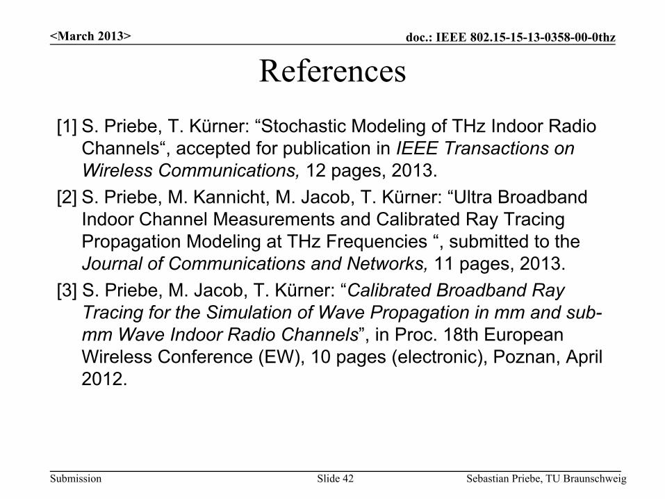
References<March 2013>
[1] S. Priebe, T. Kürner: “Stochastic Modeling of THz Indoor Radio Ch l “ t d f bli ti i IEEE T ti
References
Channels“, accepted for publication in IEEE Transactions on Wireless Communications, 12 pages, 2013.
[2] S. Priebe, M. Kannicht, M. Jacob, T. Kürner: “Ultra Broadband I d Ch l M t d C lib t d R T iIndoor Channel Measurements and Calibrated Ray Tracing Propagation Modeling at THz Frequencies “, submitted to theJournal of Communications and Networks, 11 pages, 2013.
[3] S P i b M J b T Kü “C lib t d B db d R[3] S. Priebe, M. Jacob, T. Kürner: “Calibrated Broadband Ray Tracing for the Simulation of Wave Propagation in mm and sub-mm Wave Indoor Radio Channels”, in Proc. 18th European Wireless Conference (EW) 10 pages (electronic) Poznan AprilWireless Conference (EW), 10 pages (electronic), Poznan, April 2012.
Submission Sebastian Priebe, TU BraunschweigSlide 42
doc.: IEEE 802.15-15-13-0358-00-0thz<July 2013>
Channel Realization Generator
A generator for channel realizations according to the proposedmodel has been implemented in C++ and can be obtained from theauthors for further use.The output format is „.mat“.A MATLAB installation is required.
Submission Sebastian Priebe, TU BraunschweigSlide 43
doc.: IEEE 802.15-15-13-0358-00-0thz
Technical Expectations Document (TED)<March 2013>
All information contained in this presentation is meant to be includedi th t h i l t ti d t 15 11 0745 08 0th th i
Technical Expectations Document (TED)
in the technical expectations document 15-11-0745-08-0thz-thz-ig-technical-expectations-document-ted.doc.
Submission Sebastian Priebe, TU BraunschweigSlide 44