94
June 2004 IP - Brno Design Solutions with Programmable Logic Devices and VHDL by Ing. Jeroen Lambert
| Date post: | 31-Dec-2015 |
| Category: |
Documents |
| Upload: | toby-noah-phillips |
| View: | 214 times |
| Download: | 0 times |

June 2004
IP - Brno
Design Solutions
with
Programmable Logic Devices
and VHDL
by Ing. Jeroen Lambert

2IP Brno - 2004
Overview Design Requests Electronic Design - Now and Then Technology Overview VHDL Solutions Simulation Implementation

3IP Brno - 2004
Design Requests
VME bus interface
Precise DC Motorcontroller

4IP Brno - 2004
Electronic Design - Now & Then
Previously:– PCB design - components
– digital design - logic comp
Now:– PCB design - components
– digital design - programmable
Hardware Only
Hardware&
Syntax(software)

5IP Brno - 2004
Overview Design Requests Electronic Design - Now and Then PLD solution - Technology Overview VHDL Solutions Simulation Implementation

6IP Brno - 2004
Technology Overview Programmable Logic
– What?
– PLD principle
– Devices available today
– Manufacturers

7IP Brno - 2004
What is programmable logic?
A device with configurable combinatorial logic and flip-flops linked together with programmable resources that control the interconnections
Differences between all types:– Number of gates– One time programmable / re-programmable– ‘In-system programmable’ / ‘out of system programmable’– Switch technology– Architecture (based on combinatorial logic and FF’s)

8IP Brno - 2004
What is programmable logic?
CMOSLogic
uProcessorsuControllers
StandardLogic
ProgrammableLogic
ASIC

9IP Brno - 2004
Overview Programmable Logic
– What?
– PLD principle
– Devices available today
– Manufacturers

10IP Brno - 2004
PLD principle Before programming:
Sum of product outputs
A B
A_A B
_B AND array
_ _A B
_ _A B
_ A B
_ A B
_A B
_A B
A B
A B
input lines fuses
Q1
Q2
Q3
Q4
ORarray
productlines

11IP Brno - 2004
PLD principle
PLD after programming the predefined functions:
productlines
Sum of product outputs
A B
A_A B
_B
AND array_ _A B
_ _A B
_ A B
_ A B
_A B
_A B
A B
A B
input lines fuses
Q1
Q2
Q3
Q4
ORarray

12IP Brno - 2004
Overview Programmable Logic
– What?
– PLD principle
– Devices available today
– Manufacturers

13IP Brno - 2004
Programmable logic devices available today
Major programmable logic architecture:
CMOSLogic
uProcessorsuControllers
StandardLogic
ProgrammableLogic
ASIC
SPLD CPLD FPGA

14IP Brno - 2004
SPLD - simple programmable logic device
Also known as:– PAL (Programmable Array Logic)– PLA (Programmable Logic Array)– GAL (Generic Array Logic)
Features:– smallest– fastest– least-expensive– use fuses or non-volatile memory cells like EPROM, E2PROM, FLASH
Density– 4 - 200 gates– replacement for a certain amount of 7400 series devices

15IP Brno - 2004
SPLD - simple programmable logic device
PAL architecture– 2 levels of logic gates:
AND plane:– programmable– contains product terms
OR plane:– hard-wired– contains sum of product terms
– Before programming:
O3O2 O1O0
D C B A
AND plane
OR plane

16IP Brno - 2004
SPLD - simple programmable logic device
– PAL programmed for given functions
D C B A
O3O2 O1O0
AND plane
OR plane
A.BC’.D’00A.B’.C000A.B.C’.D’A’.B’.C.D00AB.D’C.D’0

17IP Brno - 2004
SPLD - simple programmable logic device
PLA architecture– 2 levels of logic gates:
AND plane:– programmable– contains product terms
OR plane:– programmable– contains sum of the product terms
O3O2 O1O0
D C B A
AND plane
OR plane

18IP Brno - 2004
SPLD - simple programmable logic device
GAL architecture– 2 levels of logic gates:
AND plane:– programmable– contains product terms
OR array:– hard-wired with FFs– contains sum of the product terms

19IP Brno - 2004
CPLD - complex programmable logic device
Many families of different vendors:– EPLD (Erasable Programmable Logic Device)– EEPLD (Electrically-Erasable Programmable Logic Device)– 9500 CPLD Family from Xilinx– MAX (Multiple Array matriX) from Altera– ….
Use non-volatile memory cells such as EPROM, E2PROM and FLASH
Used to implement complex subsystems like UARTs, digital filters, etc.

20IP Brno - 2004
CPLD - complex programmable logic device
Higher capacity: – Typical CPLD:
equivalent with 2 to 64 SPLDs contains 10s to few hundred macrocells
– 8 to 16 macrocells (usually fully connected) grouped together in larger function block
– multiple function bocks mostly further interconnected (depends on vendor and family)
Higher density:– 150 to 45 000 gates or more– replace dozens to hundreds of 74XX series devices

21IP Brno - 2004
CPLD - complex programmable logic device

22IP Brno - 2004
CPLD - complex programmable logic device
Major variations between CPLD architectures:– number of product terms per macrocell
borrow or allocate product terms
– number of connections in the switch matrix all possible connections are supported (fully - populated)
– delays are generally fixed and predictable– no problems by routing your design
not all possible connections are supported (partially - populated)– delays are not fixed and less easily predicted– less expensive to manufacture– can give problems by routing a complex design

23IP Brno - 2004
FPGA - Field Programmable Gate Array
Consists of:– array of uncommitted logic blocks– interconnect resources– surrounded by programmable IO-blocks
Highest logic capacity:– thousands to millions of gates– thousands CLBs (Configurable Logic Block)

24IP Brno - 2004
FPGA - Field Programmable Gate Array
Architecture of FPGA:

25IP Brno - 2004
FPGA - Field Programmable Gate Array
Structure of a configurable logic block (CLB):

26IP Brno - 2004
FPGA - Field Programmable Gate Array
Structure of a programmable interconnect:

27IP Brno - 2004
FPGA - Field Programmable Gate Array
CLBs are not 100% interconnected
Logic is placed through software like PCB autorouter
Secret to density and performance:– logic in CLBs– efficiency of routing architecture
28IP Brno - 2004
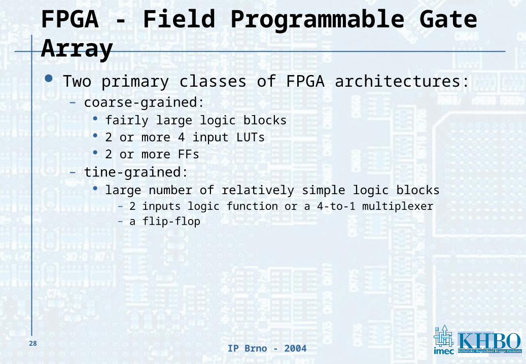
FPGA - Field Programmable Gate Array
Two primary classes of FPGA architectures:– coarse-grained:
fairly large logic blocks 2 or more 4 input LUTs 2 or more FFs
– tine-grained: large number of relatively simple logic blocks
– 2 inputs logic function or a 4-to-1 multiplexer– a flip-flop

29IP Brno - 2004
Number of gates in PLDs
4 200
150 45,000
1000 6,000,000
1 10 100 1,000 10,000 100,000 1,000,000 10,000,000
SPLD
CPLD
FPGA

30IP Brno - 2004
FPGA - Market Example
Altera - Stratix IIXilinx - Virtex II

31IP Brno - 2004
Programmable logic devices - ASIC
CMOSLogic
uProcessorsuControllers
StandardLogic
ProgrammableLogic
ASIC
SPLD CPLD FPGA

32IP Brno - 2004
ASIC - Application-Specific Integrated Circuit
Analog / Digital / MIX
Features:– customized to a specific task– not flexible– low production cost, high design cost– only for large production– possibility of migration from PLDs and FPGAs, HDL description can
be used to specify the ASIC structure (personalization)

33IP Brno - 2004
Overview
What is programmable logic?
PLD principle
Programmable logic devices available today
Overview of manufacturersOverview of manufacturers

34IP Brno - 2004
Overview of manufacturers
Altera31,5%
Xilinx30,3%
Lattice9,9%
Vantis9,8%
Actel7,4%
Lucent4,8%
Others0,6%
Phillips0,7%
QuickLogic1,4%
Atmel1,7%
Cypress1,9%

35IP Brno - 2004
Evolution
CMOSLogic
uProcessorsuControllers
StandardLogic
ProgrammableLogic
ASIC
Nios
embedded processor
IBM power pc
embedded processor

36IP Brno - 2004
Overview Design Requests Electronic Design - Now and Then Technology Overview VHDL Solutions Simulation Implementation

37IP Brno - 2004
Overview
What is VHDL, Applications, Benefits and Design What is VHDL, Applications, Benefits and Design Flow?Flow?
VHDL language and syntax– General
– Structure of a .VHD file
– Concurrent & Sequential Statements
– Synchronous logic & State machines

38IP Brno - 2004
What is VHDL
VHDL = double acronym– VHDL = VHSIC Hardware Description Language– VHSIC = Very High Speed Integrated Circuit
Developed in the early 80s by the American Department of Defense
Defined by international standards– IEEE Std 1076 – 1987 – IEEE Std 1076 – 1993

39IP Brno - 2004
Application area
Describe architecture and behavior of discrete electronic systems
Modeling System Hardware
Embedded systems: co-design & co-verification
Hardware Implementation: CPLD, FPGA, ...

40IP Brno - 2004
Benefits of Using VHDL
Design at higher level– very powerful language constructs– locate problems in early stage
Device independent– use same code for different target devices– choice of tools & vendors
Flexibility– IP re-use: libraries & components
Top-down philosophy– large projects with different teams of designers– functional simulation of building blocks
Quick time-to-market and low cost

41IP Brno - 2004
Limitations/drawbacks
Only digital system design
The VHDL code may not always describe an optimal function
Not always most effective use of resources

42IP Brno - 2004
Abstraction levels
BehaviouralBehavioural
LayoutLayout
RTLRTL
LogicLogic
f

43IP Brno - 2004
Abstraction levels (Cont’d) Behaviour level:
– functional description of the model– no system clock– simulatable, not synthesizable– to create stimuli
RT (Register Transfer) level:– combinatorial logic and storage elements– system clock– simulatable and synthesizable
Logic level:– interconnect of logic gates and storage elements– detailed timing
Layout:– detailed timing

44IP Brno - 2004
Design flow
BehaviouralBehavioural
RTLRTL
LogicLogic
VHDL editorVHDL editor
optimisationoptimisation
Device fittingor
Place & RouteSoftware
Device fittingor
Place & RouteSoftware LayoutLayout
Device independent
Device dependent

45IP Brno - 2004
Top-down design philosophy
Allows:– early testing– easy change of technology– structured system design
Results OK?
Results OK?
Design entryDesign entry
SimulationSimulation
Synthesis/optimisationSynthesis/optimisation
Timing analysisand layout
Timing analysisand layout
yes
no
yes
no

46IP Brno - 2004
Overview
What is VHDL, Applications, Benefits and Design Flow? VHDL language and syntaxVHDL language and syntax
– GeneralGeneral
– Structure of a .VHD file
– Concurrent & Sequential Statements
– Synchronous logic & State machines

47IP Brno - 2004
General
Case insensitive– VHDL keyword: lower case letters– self defined identifiers: upper case letters
Sequential statements– executed one after another– functions, procedures
Concurrent statements– executed in parallel– instantiation

48IP Brno - 2004
General (Cont’d)
Signal types:– each signal has a type– VHDL provides predefined types
bit bit_vector integer ….
– user can define his own types makes the code more readable useful in state machines
Process
bit
integer
Std_logic
bit _vector (0 to 3)
my_type
Process
Process
Process

49IP Brno - 2004
Overview
What is VHDL, Applications, Benefits and Design Flow? VHDL language and syntaxVHDL language and syntax
– General
– Structure of a .VHD fileStructure of a .VHD file
– Concurrent & Sequential Statements
– Synchronous logic & State machines

50IP Brno - 2004
Entity
Describes the interface or black box No behavioral description
SUM
CARRY
A
B
entity HALFADD is
port(A : in std_logic;
B : in std_logic;
SUM, CARRY : out std_logic
);
end HALFADD;
entity HALFADD is
port(A : in std_logic;
B : in std_logic;
SUM, CARRY : out std_logic
);
end HALFADD;

51IP Brno - 2004
Port modes
IN: – read-only, no signal update
OUT:– write-only, signal update
BUFFER:– read, signal update
INOUT:– bi-directional data flow
!!! PORT MODES HAVE TO MATCH
entity EXAMPLE is
port(A : in std_logic;
B : out integer;
C : inout bit;
D : buffer std_logic);
end EXAMPLE;
entity EXAMPLE is
port(A : in std_logic;
B : out integer;
C : inout bit;
D : buffer std_logic);
end EXAMPLE;

52IP Brno - 2004
Architecture
Internal view of black box, description of the functionality of the entity
must be associated with a specific entity one entity can have several architectures contains concurrent statements
SUM
CARRY
A
B+
architecture BEHAVE of HALFADD is
-- declaration part
begin
-- definition part
SUM <= A xor B;
CARRY <= A and B;
end BEHAVE;
architecture BEHAVE of HALFADD is
-- declaration part
begin
-- definition part
SUM <= A xor B;
CARRY <= A and B;
end BEHAVE;

53IP Brno - 2004
Structural description
Example: full adder
Contents of top-level full adder:– 2 x component half adder from library– signals to connect building blocks
U1
N_SUM
CARRY
A
B
U2
CINN_CARRY1
N_CARRY2
SUM
54IP Brno - 2004
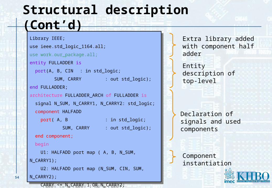
Structural description (Cont’d)
Library IEEE;
use ieee.std_logic_1164.all;
use work.our_package.all;
entity FULLADDER is
port(A, B, CIN : in std_logic;
SUM, CARRY : out std_logic);
end FULLADDER;
architecture FULLADDER_ARCH of FULLADDER is
signal N_SUM, N_CARRY1, N_CARRY2: std_logic;
component HALFADD
port( A, B : in std_logic;
SUM, CARRY : out std_logic);
end component;
begin
U1: HALFADD port map ( A, B, N_SUM, N_CARRY1);
U2: HALFADD port map (N_SUM, CIN, SUM, N_CARRY2);
CARRY <= N_CARRY 1 OR N_CARRY2;
end BUFFER_ARCH;
Extra library added with component half adder
Entity description of top-level
Declaration of signals and used components
Component instantiation

55IP Brno - 2004
Process
Within an architecture Contains sequential statements Triggered by signals in sensitivity list Multiple processes interact
concurrently
architecture ….. of ….. is
begin
process (a,b,c)
begin
-- sequential statements
end process;
clock: process (d,e)
begin
-- sequential statements
end process clock;
end …..;
architecture ….. of ….. is
begin
process (a,b,c)
begin
-- sequential statements
end process;
clock: process (d,e)
begin
-- sequential statements
end process clock;
end …..;
Process
Seq
uent
ial
Parallel
Process
Seq
uent
ial
Parallel
Process
Seq
uent
ial
Parallel
Process
Seq
uent
ial
Parallel

56IP Brno - 2004
Library
Collection of compiled design units– entity, architecture, package, package body, configuration
Exists physically as a directory
Predefined libraries are “ieee” and “work”
IP blocks

57IP Brno - 2004
Overview
What is VHDL, Applications, Benefits and Design Flow? VHDL language and syntaxVHDL language and syntax
– General
– Structure of a .VHD file
– Concurrent & Sequential StatementsConcurrent & Sequential Statements
– Synchronous logic & State machines

58IP Brno - 2004
Difference
Concurrent StatementsAre executed outside a processAre executed at the same timeOrder independent = no priority
Sequential StatementsAre executed within a processAre executed one at a timeOrder dependent = priority

59IP Brno - 2004
Conditional signal assignment : ‘when’
Only one target Must have an unconditional ‘else’ Conditions can overlap Priority encoding !!
entity BRANCH is
port ( A, B, C, X, Y : in integer range 0 to 7;
Z : out integer range 0 to 7);
end BRANCH;
architecture USE_CONDITIONAL of BRANCH is
begin
Z <= A when X > 5 else
B when Y < 7 else
C;
end USE_CONDITIONAL;
entity BRANCH is
port ( A, B, C, X, Y : in integer range 0 to 7;
Z : out integer range 0 to 7);
end BRANCH;
architecture USE_CONDITIONAL of BRANCH is
begin
Z <= A when X > 5 else
B when Y < 7 else
C;
end USE_CONDITIONAL;

60IP Brno - 2004
Process Structure
Executed when event on signal in sensitivity list Signals updated AT END of process Any signals can be in list A process can be running or suspended
MUX: process (A, B, SEL )
begin
if SEL = ‘1’ then
Z <= A ;
else
Z <= B ;
end if;
end process MUX;
MUX: process (A, B, SEL )
begin
if SEL = ‘1’ then
Z <= A ;
else
Z <= B ;
end if;
end process MUX;
Sensitivity List
Label

61IP Brno - 2004
Overview
What is VHDL, Applications, Benefits and Design Flow? VHDL language and syntaxVHDL language and syntax
– General
– Structure of a .VHD file
– Concurrent & Sequential Statements
– Synchronous logic & State machinesSynchronous logic & State machines

62IP Brno - 2004
Clocked events
Rule:No other statements allowed outside the “if” structure
No “else” clause
Rising Clock Edge Falling Clock Edge
process ( CLK ) begin
if ( CLK’event and CLK = ‘1’ ) then -- Default assignments -- Combinational logic end if;end process;
process ( CLK ) begin
if ( CLK’event and CLK = ‘1’ ) then -- Default assignments -- Combinational logic end if;end process;
process ( CLK ) begin
if ( CLK’event and CLK = ‘0’ ) then -- Default assignments -- Combinational logic end if;end process;
process ( CLK ) begin
if ( CLK’event and CLK = ‘0’ ) then -- Default assignments -- Combinational logic end if;end process;

63IP Brno - 2004
Resets
Rules:No other statements allowed outside the “if” structuresNo “else” clause after the edge detection
Asynchronous Reset Synchronous Reset
process ( CLK , RST ) begin
if ( RST = ‘0’ ) then
-- Combinational logic
elsif ( CLK’event and CLK = ‘1’ ) then -- Default statements -- Combinational logic end if;end process;
process ( CLK , RST ) begin
if ( RST = ‘0’ ) then
-- Combinational logic
elsif ( CLK’event and CLK = ‘1’ ) then -- Default statements -- Combinational logic end if;end process;
process ( CLK ) begin
if ( CLK’event and CLK = ‘1’ ) then
if ( RST = ‘0’ ) then -- Combinational logic else -- Default statements -- Combinational logic end if ; end if;end process;
process ( CLK ) begin
if ( CLK’event and CLK = ‘1’ ) then
if ( RST = ‘0’ ) then -- Combinational logic else -- Default statements -- Combinational logic end if ; end if;end process;

64IP Brno - 2004
What are State Machines?
= any device that – stores a status at a given time
– operates on input to change status or perform action
State Machines solve many design problems– very popular technique
– easy to implement in many PLDs
State Machines in VHDL = translating a state diagram

65IP Brno - 2004
Moore – Mealy State Machines Mealy State Machine
outputs depend on:– State
– Inputs
OUTPUT_LOGIC: process ( STATE, RW, INT_REQ, DMA_REQ)
begin
-- Default output assignments
case STATE is
when IDLE =>
-- Output assignments
when RW_CYCLE =>
-- Output assignments
when INT_CYCLE =>
-- Output assignments
when DMA_CYCLE =>
-- Output assignments
end case ;
end process OUTPUT_LOGIC ;
code ex. 1 – Mealy State Machine

66IP Brno - 2004
Moore – Mealy State Machines Moore State Machine
outputs depend only:– State
OUTPUT_LOGIC: process ( STATE )
begin
-- Default output assignments
case STATE is
when IDLE =>
-- Output assignments
when RW_CYCLE =>
-- Output assignments
when INT_CYCLE =>
-- Output assignments
when DMA_CYCLE =>
-- Output assignments
end case ;
end process OUTPUT_LOGIC ;
code ex. 2 – Moore State Machine

67IP Brno - 2004
A simple design exampleSlave device responding to R/W cycles of a master State Diagram
IDLE
DECISION
AS_N = ‘0’
WRITEST READST
WRITE = ‘1’ WRITE = ‘0’
AS_N = ‘1’

68IP Brno - 2004
A simple design exampleSlave device responding to R/W cycles of a master VHDL code
case CurrentState is
when IDLE =>
DataOut <= (others => '0');
if(AS_N = '0') then
CurrentState <= DECISION;
else
CurrentState <= IDLE;
end if;
when DECISION =>
if(WRITE = '1') then -- write cycle
CurrentState <= WRITEST;
else
CurrentState <= READST;
end if;
…
case CurrentState is
when IDLE =>
DataOut <= (others => '0');
if(AS_N = '0') then
CurrentState <= DECISION;
else
CurrentState <= IDLE;
end if;
when DECISION =>
if(WRITE = '1') then -- write cycle
CurrentState <= WRITEST;
else
CurrentState <= READST;
end if;
…

69IP Brno - 2004
A simple design example VHDL code continued
when WRITEST =>
DataOut <= InternalRegister;
if(AS_N = '1') then
CurrentState <= IDLE;
else
CurrentState <= WRITEST;
end if;
when READST =>
InternalRegister <= DataIn;
CurrentState <= IDLE;
when others =>
end case;
when WRITEST =>
DataOut <= InternalRegister;
if(AS_N = '1') then
CurrentState <= IDLE;
else
CurrentState <= WRITEST;
end if;
when READST =>
InternalRegister <= DataIn;
CurrentState <= IDLE;
when others =>
end case;

70IP Brno - 2004
Overview Design Requests Electronic Design - Now and Then Technology Overview VHDL Solutions Simulation Implementation

71IP Brno - 2004
Overview
Shift Register
DC Motor Controller– Quadrature Encoder
– LED display driver

72IP Brno - 2004
Shift Register Design Specs
– 16 bit register
– parallel load (if p_load is high)
– normal shift register if p_load is low
– asynchronous reset
16 bit
Shift
Register
16 bit
p_in
p_out
p_load
rst
clk
s_in
s_out

73IP Brno - 2004
Solutions - Shift Register
Library IEEE;use IEEE.std_logic_1164.all;
entity ShiftReg is port( rst_n : in std_logic; clk : in std_logic; s_in: in std_logic; p_load: in std_logic; p_in: in std_logic_vector(15 downto 0); s_out: out std_logic; p_out: out std_logic_vector(15 downto 0));end ShiftReg;
Library IEEE;use IEEE.std_logic_1164.all;
entity ShiftReg is port( rst_n : in std_logic; clk : in std_logic; s_in: in std_logic; p_load: in std_logic; p_in: in std_logic_vector(15 downto 0); s_out: out std_logic; p_out: out std_logic_vector(15 downto 0));end ShiftReg;
architecture Behave of ShiftReg is
signal p_out_i: std_logic_vector(15 downto 0);
begin
process(clk,rst_n)begin if(rst_n = '0') then p_out_i <= (others => '0'); s_out <= '0'; elsif(clk'event and clk = '1') then if(p_load = '1') then p_out_i <= p_in; else p_out_i(14 downto 0) <= p_out_i(15 downto 1); p_out_i(15) <= s_in; s_out <= p_out_i(0); end if; end if;end process;
p_out <= p_out_i;
end BEHAVE;

74IP Brno - 2004
DC Motor Controller Design Specs
– DC vs. Stepper motor
– 12-bit resolution position control
– display position

75IP Brno - 2004
DC Motor Controller practical implementation

76IP Brno - 2004
DC Motor Controller position determination
– Home Switch
– Optical Encoder

77IP Brno - 2004
DC Motor Controller encoder outputs
rotation
amplitude
Ch.B
Ch.A

78IP Brno - 2004
DC Motor Controller encoder outputs
rotation
amplitude
Ch.B = ‘1’
Ch.A = ‘1’

79IP Brno - 2004
DC Motor Controller encoder outputs
rotation
amplitude
Ch.B = ‘1’
Ch.A = ‘0’

80IP Brno - 2004
DC Motor Controller encoder outputs
rotation
amplitude
Ch.B = ‘0’
Ch.A = ‘0’

81IP Brno - 2004
DC Motor Controller encoder outputs
rotation
amplitude
Ch.B = ‘1’
Ch.A = ‘0’

82IP Brno - 2004
DC Motor Controller LED display driver
– drive 4 LED displays
– only divide/multiply by powers of 2
clkrst_n
11..0position
?

83IP Brno - 2004
Solution - DC Motor Controller State Machine
STATE 0
A = 1
B = 0
STATE 1
A = 1
B = 1
STATE 3
A = 0
B = 0
STATE 2
A = 0
B = 1
UP
UP
UP
UPDOWN
DOWNDOWN
DOWN

84IP Brno - 2004
Solution DC Motor Controller Translation State Machine - VHDL part I
process(Reset_N,Clk,) -- counting encoder pulses begin if(Reset_N = '0) then Plus <= '0'; Minus <= '0'; CurrentState <= STATE0; elsif(Clk'event and Clk = '1') then Plus <= '0'; Minus <= '0';
case CurrentState is
when STATE0 => -- 10 if(Wave_I = "11") then Plus <= '1'; CurrentState <= STATE1; elsif(Wave_I = "00") then Minus <= '1'; CurrentState <= STATE3; else CurrentState <= STATE0; end if;
when STATE1 => -- 11 if(Wave_I = "01") then Plus <= '1'; CurrentState <= STATE2; elsif(Wave_I = "10") then Minus <= '1'; CurrentState <= STATE0; else CurrentState <= STATE1; end if;
when STATE2 => -- 01 if(Wave_I = "00") then Plus <= '1'; CurrentState <= STATE3; elsif(Wave_I = "11") then Minus <= '1'; CurrentState <= STATE1; else CurrentState <= STATE2; end if;

85IP Brno - 2004
Solution DC Motor Controller Translation State Machine - VHDL part II
when STATE3 => -- 00 if(Wave_I = "10") then Plus <= '1'; CurrentState <= STATE0; elsif(Wave_I = "01") then Minus <= '1'; CurrentState <= STATE2; else CurrentState <= STATE3; end if; end case; end if; end process;
when STATE3 => -- 00 if(Wave_I = "10") then Plus <= '1'; CurrentState <= STATE0; elsif(Wave_I = "01") then Minus <= '1'; CurrentState <= STATE2; else CurrentState <= STATE3; end if; end case; end if; end process;
86IP Brno - 2004
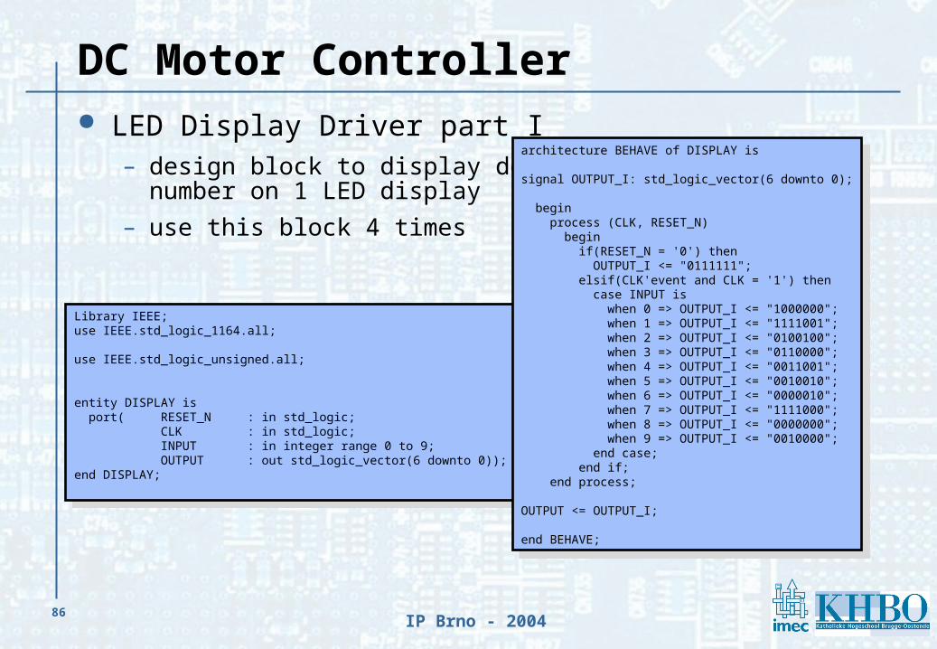
DC Motor Controller LED Display Driver part I
– design block to display decimalnumber on 1 LED display
– use this block 4 times
Library IEEE;use IEEE.std_logic_1164.all;
use IEEE.std_logic_unsigned.all;
entity DISPLAY is port( RESET_N : in std_logic; CLK : in std_logic; INPUT : in integer range 0 to 9; OUTPUT : out std_logic_vector(6 downto 0));end DISPLAY;
Library IEEE;use IEEE.std_logic_1164.all;
use IEEE.std_logic_unsigned.all;
entity DISPLAY is port( RESET_N : in std_logic; CLK : in std_logic; INPUT : in integer range 0 to 9; OUTPUT : out std_logic_vector(6 downto 0));end DISPLAY;
architecture BEHAVE of DISPLAY is
signal OUTPUT_I: std_logic_vector(6 downto 0);
begin process (CLK, RESET_N) begin if(RESET_N = '0') then OUTPUT_I <= "0111111"; elsif(CLK'event and CLK = '1') then case INPUT is
when 0 => OUTPUT_I <= "1000000";when 1 => OUTPUT_I <= "1111001"; when 2 => OUTPUT_I <= "0100100";when 3 => OUTPUT_I <= "0110000";when 4 => OUTPUT_I <= "0011001";when 5 => OUTPUT_I <= "0010010";when 6 => OUTPUT_I <= "0000010";when 7 => OUTPUT_I <= "1111000";when 8 => OUTPUT_I <= "0000000";when 9 => OUTPUT_I <= "0010000";
end case; end if; end process;
OUTPUT <= OUTPUT_I;
end BEHAVE;

87IP Brno - 2004
DC Motor Controller LED Display Driver part II
– design block to convertnumber into 4 decimals
Library IEEE;use IEEE.std_logic_1164.all;use IEEE.std_logic_unsigned.all;
entity DISPLAY_CONV isport( RESET_N : in std_logic; CLK : in std_logic; INPUT : in std_logic_vector(11 downto 0); THOUSAND: out integer range 0 to 9;
HUNDRED : out integer range 0 to 9; TEN : out integer range 0 to 9; UNIT : out integer range 0 to 9);end DISPLAY_CONV;
architecture BEHAVE of DISPLAY_CONV is
Type Status is (STATE1,STATE2,STATE3,STATE4,STATE5, STATE6,STATE7);signal CurrentState: Status;signal INPUT_I : std_logic_vector(11 downto 0);signal INPUTDEC: integer range 0 to 4095; -- 2^12 = 4096signal TEN_I : integer range 0 to 9;signal UNIT_I : integer range 0 to 9;signal HUNDRED_I: integer range 0 to 9;signal THOUSAND_I: integer range 0 to 9;begin
process(CLK, RESET_N)begin if(RESET_N = '0') then HUNDRED <= 0; TEN <= 0; UNIT <= 0; THOUSAND <= 0; CurrentState <= STATE1; TEN_I <= 0; UNIT_I <= 0; HUNDRED_I <= 0; THOUSAND_I <= 0; INPUTDEC <= 0; INPUT_I <= "000000000000";

88IP Brno - 2004
DC Motor Controller LED Display Driver part III
elsif(CLK'event and CLK = '1') then case CurrentState is when STATE1 => -- get inputvector INPUT_I <= INPUT; CurrentState <= STATE2; when STATE2 => -- convert to integer INPUTDEC <= CONV_INTEGER(INPUT_I); CurrentState <= STATE3; THOUSAND_I <= 0; HUNDRED_I <= 0; TEN_I <= 0; UNIT_I <= 0;
when STATE3 => if(INPUTDEC >= 1000) then INPUTDEC <= INPUTDEC - 1000; THOUSAND_I <= THOUSAND_I + 1; else CurrentState <= STATE4; end if;
when STATE4 => if(INPUTDEC >= 100) then INPUTDEC <= INPUTDEC - 100; HUNDRED_I <= HUNDRED_I + 1; else CurrentState <= STATE5; end if;
when STATE5 => if(INPUTDEC >= 10) then INPUTDEC <= INPUTDEC - 10; TEN_I <= TEN_I + 1; else CurrentState <= STATE6; end if;
when STATE6 => UNIT_I <= INPUTDEC; CurrentState <= STATE7;
when STATE7 => THOUSAND <= THOUSAND_I; HUNDRED <= HUNDRED_I; TEN <= TEN_I; UNIT <= UNIT_I; CurrentState <= STATE1; end case; end if;end process;
end BEHAVE;

89IP Brno - 2004
Overview Design Requests Electronic Design - Now and Then Technology Overview VHDL Solutions Simulation Implementation

90IP Brno - 2004
Simulation Modelsim
– shift register
– motor controller
free version @
http://www.model.com

91IP Brno - 2004
Overview Design Requests Electronic Design - Now and Then Technology Overview VHDL Solutions Simulation Implementation

92IP Brno - 2004
Implementation
Xilinx ISE Webpack
free @
http://www.xilinx.com
Altera Quartus
free @
http://www.altera.com

93IP Brno - 2004
FPGA - internal mapping

94IP Brno - 2004
Thank you for your attention !


