55
Karbon 700 BIOS Manual www.logicsupply.com

Karbon 700 BIOS Manual
www.logicsupply.com

Main Page InsydeH2O Version
Type Information
Found on BIOS Page Main Page
Description Displays current InsydeH2O version
BIOS Version
Type Information
Found on BIOS Page Main Page
Description Displays current BIOS version
Build Date
Type Information
Found on BIOS Page Main Page
Description Displays the build date in MM/DD/YYYY
Processor Type
Type Information
Found on BIOS Page Main Page
Description Displays current processor
CPU Speed
Type Information
Found on BIOS Page Main Page
Description Displays CPU rated speed
1
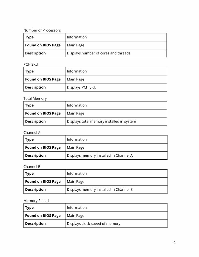
Number of Processors
Type Information
Found on BIOS Page Main Page
Description Displays number of cores and threads
PCH SKU
Type Information
Found on BIOS Page Main Page
Description Displays PCH SKU
Total Memory
Type Information
Found on BIOS Page Main Page
Description Displays total memory installed in system
Channel A
Type Information
Found on BIOS Page Main Page
Description Displays memory installed in Channel A
Channel B
Type Information
Found on BIOS Page Main Page
Description Displays memory installed in Channel B
Memory Speed
Type Information
Found on BIOS Page Main Page
Description Displays clock speed of memory
2

Language
Type Information
Found on BIOS Page Main Page
Description Select the current default language used by the InsydeH2O
System Time
Type Information
Found on BIOS Page Main Page
Description Display the time in HH:MM:SS. Valid range is from 0 to 23, 0 to 59, 0 to 59. Use +/- to increase/reduce
System Date
Type Information
Found on BIOS Page Main Page
Description Display the date in MM:DD:YYYY. Valid range is from 1 to 12, 1 to 31, 2000 to 2099. Use +/- to increase/reduce
3

Advanced Page Boot Configuration
Type Configurable Setting
Found on BIOS Page Advanced Page
Description Configures boot settings
Advanced Page > Boot Configuration Numlock
Type Configurable Setting
Found on BIOS Page Advanced Page > Boot Configuration
Description Selects Power-on state for numlock. Possible values: Off/On, default value: Off
SATA Configuration
Type Configurable Setting
Found on BIOS Page Advanced Page
Description Select the SATA controller and hard disk drive type installed in your system
Advanced Page > SATA Configuration SATA ATA Port X
Type Information
Found on BIOS Page Advanced Page > SATA Configuration
Description Displays SKU of device currently installed in SATA Port
4
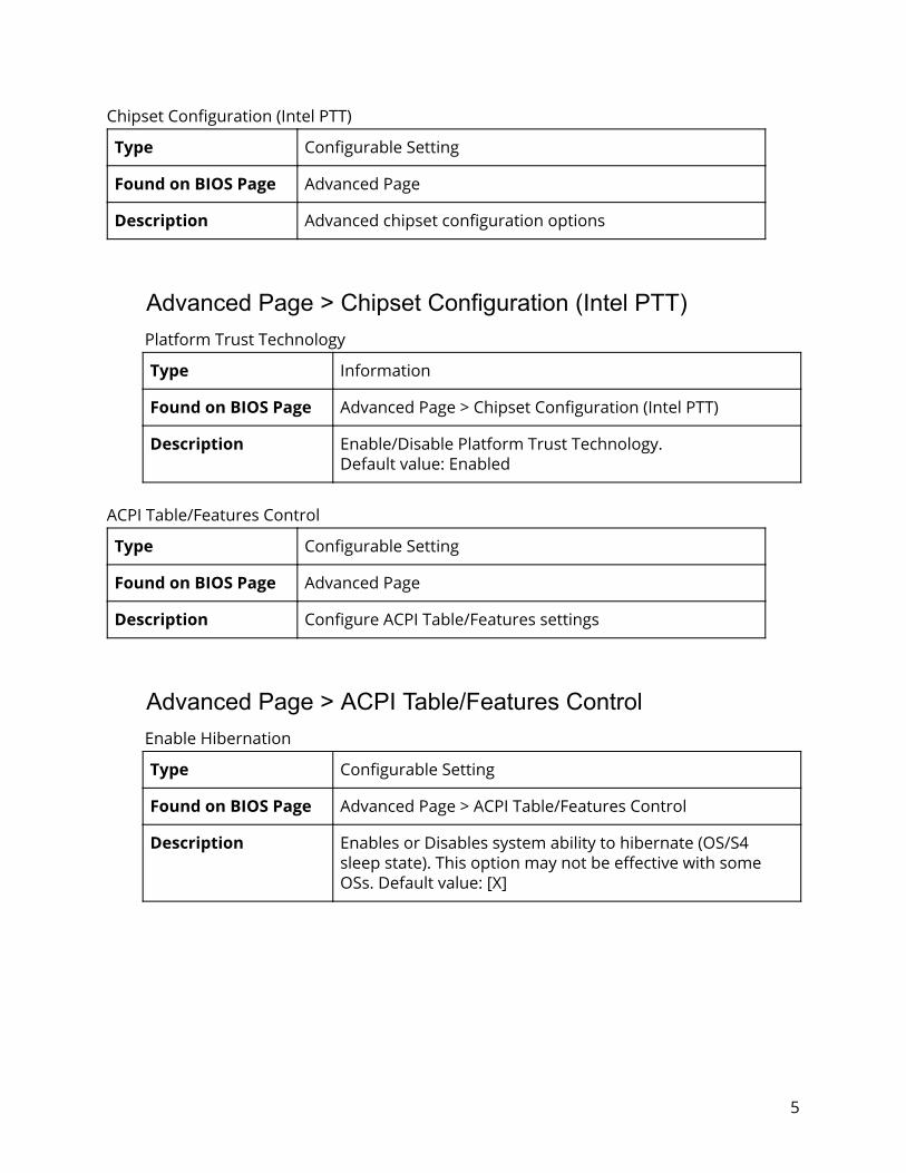
Chipset Configuration (Intel PTT)
Type Configurable Setting
Found on BIOS Page Advanced Page
Description Advanced chipset configuration options
Advanced Page > Chipset Configuration (Intel PTT) Platform Trust Technology
Type Information
Found on BIOS Page Advanced Page > Chipset Configuration (Intel PTT)
Description Enable/Disable Platform Trust Technology. Default value: Enabled
ACPI Table/Features Control
Type Configurable Setting
Found on BIOS Page Advanced Page
Description Configure ACPI Table/Features settings
Advanced Page > ACPI Table/Features Control Enable Hibernation
Type Configurable Setting
Found on BIOS Page Advanced Page > ACPI Table/Features Control
Description Enables or Disables system ability to hibernate (OS/S4 sleep state). This option may not be effective with some OSs. Default value: [X]
5
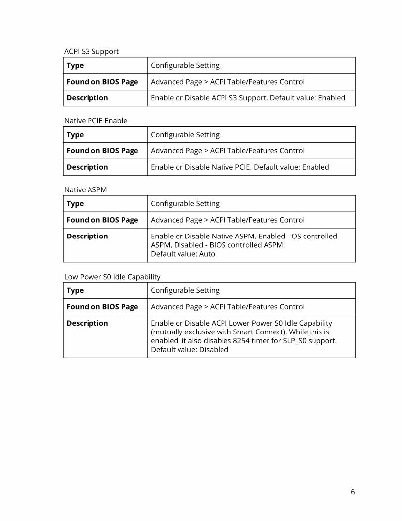
ACPI S3 Support
Type Configurable Setting
Found on BIOS Page Advanced Page > ACPI Table/Features Control
Description Enable or Disable ACPI S3 Support. Default value: Enabled
Native PCIE Enable
Type Configurable Setting
Found on BIOS Page Advanced Page > ACPI Table/Features Control
Description Enable or Disable Native PCIE. Default value: Enabled
Native ASPM
Type Configurable Setting
Found on BIOS Page Advanced Page > ACPI Table/Features Control
Description Enable or Disable Native ASPM. Enabled - OS controlled ASPM, Disabled - BIOS controlled ASPM. Default value: Auto
Low Power S0 Idle Capability
Type Configurable Setting
Found on BIOS Page Advanced Page > ACPI Table/Features Control
Description Enable or Disable ACPI Lower Power S0 Idle Capability (mutually exclusive with Smart Connect). While this is enabled, it also disables 8254 timer for SLP_S0 support. Default value: Disabled
6
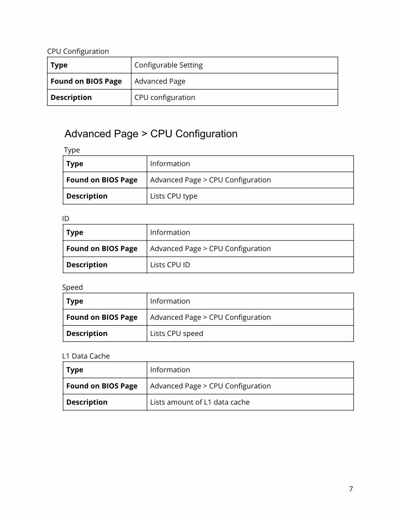
CPU Configuration
Type Configurable Setting
Found on BIOS Page Advanced Page
Description CPU configuration
Advanced Page > CPU Configuration Type
Type Information
Found on BIOS Page Advanced Page > CPU Configuration
Description Lists CPU type
ID
Type Information
Found on BIOS Page Advanced Page > CPU Configuration
Description Lists CPU ID
Speed
Type Information
Found on BIOS Page Advanced Page > CPU Configuration
Description Lists CPU speed
L1 Data Cache
Type Information
Found on BIOS Page Advanced Page > CPU Configuration
Description Lists amount of L1 data cache
7
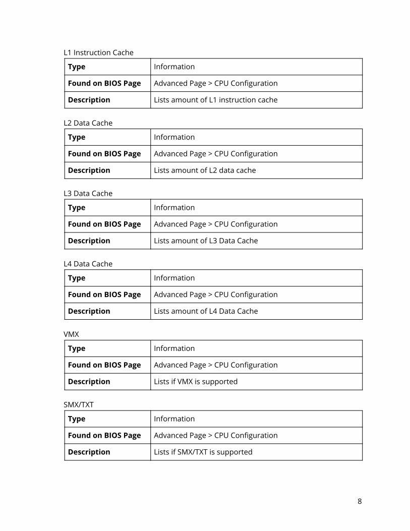
L1 Instruction Cache
Type Information
Found on BIOS Page Advanced Page > CPU Configuration
Description Lists amount of L1 instruction cache
L2 Data Cache
Type Information
Found on BIOS Page Advanced Page > CPU Configuration
Description Lists amount of L2 data cache
L3 Data Cache
Type Information
Found on BIOS Page Advanced Page > CPU Configuration
Description Lists amount of L3 Data Cache
L4 Data Cache
Type Information
Found on BIOS Page Advanced Page > CPU Configuration
Description Lists amount of L4 Data Cache
VMX
Type Information
Found on BIOS Page Advanced Page > CPU Configuration
Description Lists if VMX is supported
SMX/TXT
Type Information
Found on BIOS Page Advanced Page > CPU Configuration
Description Lists if SMX/TXT is supported
8
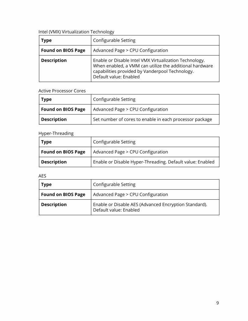
Intel (VMX) Virtualization Technology
Type Configurable Setting
Found on BIOS Page Advanced Page > CPU Configuration
Description Enable or Disable Intel VMX Virtualization Technology. When enabled, a VMM can utilize the additional hardware capabilities provided by Vanderpool Technology. Default value: Enabled
Active Processor Cores
Type Configurable Setting
Found on BIOS Page Advanced Page > CPU Configuration
Description Set number of cores to enable in each processor package
Hyper-Threading
Type Configurable Setting
Found on BIOS Page Advanced Page > CPU Configuration
Description Enable or Disable Hyper-Threading. Default value: Enabled
AES
Type Configurable Setting
Found on BIOS Page Advanced Page > CPU Configuration
Description Enable or Disable AES (Advanced Encryption Standard). Default value: Enabled
9

Power & Performance
Type Configurable Setting
Found on BIOS Page Advanced Page
Description Power and performance
Boot Performance Mode
Type Configurable Setting
Found on BIOS Page Advanced Page > Power & Performance
Description Select the performance state that the BIOS will set starting from reset vector. Possible values: Max Non-Turbo Performance / Max Battery / Turbo Performance. Default value: Max Non-Turbo Performance
Intel(R) SpeedStep(tm)
Type Configurable Setting
Found on BIOS Page Advanced Page > Power & Performance
Description Allows more than two frequency ranges to be supported. Default value: Enabled
Intel(R) Speed Shift Technology
Type Configurable Setting
Found on BIOS Page Advanced Page > Power & Performance
Description Enable or Disable Intel(R) Speed Shift Technology support. Enabling will expose the CPPC v2 interface to allow for hardware controlled P-states. Default value: Enabled
Turbo Mode
Type Configurable Setting
Found on BIOS Page Advanced Page > Power & Performance
Description Enable or Disable processor Turbo Mode (requires Intel Speed Step or Intel Speed Shift to be available and enabled). Default value: Enabled
10

Configurable TDP Settings
Type Configurable Setting
Found on BIOS Page Advanced Page
Description Configurable TDP settings
Configurable TDP Boot Mode
Type Configurable Setting
Found on BIOS Page Advanced Page > Configurable TDP Settings
Description Configurable TDP Mode TDP selection. Deactivate option will set MSR to Nominal and MMIO to Zero. Possible values: Nominal / Down / Deactivate Default value: Nominal
Configurable TDP Lock
Type Configurable Setting
Found on BIOS Page Advanced Page > Configurable TDP Settings
Description Configurable TDP Mode Lock sets the Lock bits on TURBO_ACTIVATION_RATIO and CONFIG_TDP_CONTROL. Note: When CTDP Lock is enabled Custom ConfigTDP Count will be forced to 1 and Custom ConfigTDP Boot Index will be forced to 0. Default value: Disabled
CTDP BIOS Control
Type Configurable Setting
Found on BIOS Page Advanced Page > Configurable TDP Settings
Description Enable or Disable CTDP control via runtime ACPI BIOS methods. This “BIOS only” feature does not require EC or driver support. Default value: Disabled
11

Memory Configuration
Type Configurable Setting
Found on BIOS Page Advanced Page
Description Memory Configuration Parameters
HOB Buffer Size
Type Configurable Setting
Found on BIOS Page Advanced Page > Memory Configuration
Description Set HOB buffer size. Possible values: Auto / 1B / 1KB / Max (assuming 63KB total HOB size). Default value: Auto
ECC Support
Type Configurable Setting
Found on BIOS Page Advanced Page > Memory Configuration
Description Enable or Disable ECC Support. Default value: Enabled
Max TOLUD
Type Configurable Setting
Found on BIOS Page Advanced Page > Memory Configuration
Description Maximum value of TOLUD. Dynamic assignment would adjust TOLUD automatically based on largest MMIO length of installed graphic controller. Possible value: 1, 1.25, 1.5, 1.75, 2, 2.25, 2.5, 2.75, 3, 3.25, 3.5 (GB). Default value: Dynamic
12

System Agent (SA) Configuration
Type Configurable Setting
Found on BIOS Page Advanced Page
Description System Agent (SA) Parameters
SA PCIe Code Version
Type Information
Found on BIOS Page Advanced Page > System Agent (SA) Configuration
Description Displays SA PCIe Code Version
VT-d
Type Information
Found on BIOS Page Advanced Page > System Agent (SA) Configuration
Description Lists VT-d support
Graphics Configuration
Type Configurable Setting
Found on BIOS Page Advanced Page > System Agent (SA) Configuration
Description Graphics configuration
Stop Grant Configuration
Type Configurable Setting
Found on BIOS Page Advanced Page > System Agent (SA) Configuration
Description Automatic/Manual stop grant configuration. Default value: Auto
PCIe Spread Spectrum Clocking
Type Configurable Setting
Found on BIOS Page Advanced Page > System Agent (SA) Configuration
Description Allows disabling Spread Spectrum Clocking for compliance testing. Default value: Enabled
13

VT-d
Type Configurable Setting
Found on BIOS Page Advanced Page > System Agent (SA) Configuration
Description Enable or Disable VT-d capability. Default value: Enabled
CHAP Device (B0:D7:F0)
Type Configurable Setting
Found on BIOS Page Advanced Page > System Agent (SA) Configuration
Description Enable or Disable SA CHAP Device. Default value: Disabled
Thermal Device (B0:D4:F0)
Type Configurable Setting
Found on BIOS Page Advanced Page > System Agent (SA) Configuration
Description Enable or Disable SA Thermal Device. Default value: Disabled
GNA Device (B0:D8:F0)
Type Configurable Setting
Found on BIOS Page Advanced Page > System Agent (SA) Configuration
Description Enable or Disable SA GNA Device. Default value: Disabled
CRID Support
Type Configurable Setting
Found on BIOS Page Advanced Page > System Agent (SA) Configuration
Description Enable or Disable CRID control for Intel SIPP. Default value: Disabled
14

Above 4GB MMIO BIOS assignment
Type Configurable Setting
Found on BIOS Page Advanced Page > System Agent (SA) Configuration
Description Enable or Disable above 4GB MemoryMappedIO BIOS assignment. This is enabled automatically when Aperture Size is set to 2048MB. Default value: Disabled
X2APIC Opt Out
Type Configurable Setting
Found on BIOS Page Advanced Page > System Agent (SA) Configuration
Description Enable or Disable X2APIC_OPT_OUT bit. Default value: Disabled
IPU Device (B0:D5:F0)
Type Configurable Setting
Found on BIOS Page Advanced Page > System Agent (SA) Configuration
Description Enable or Disable SA IPU Device. Default value: Disabled
15
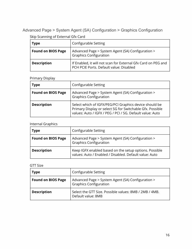
Advanced Page > System Agent (SA) Configuration > Graphics Configuration Skip Scanning of External Gfx Card
Type Configurable Setting
Found on BIOS Page Advanced Page > System Agent (SA) Configuration > Graphics Configuration
Description If Enabled, it will not scan for External Gfx Card on PEG and PCH PCIE Ports. Default value: Disabled
Primary Display
Type Configurable Setting
Found on BIOS Page Advanced Page > System Agent (SA) Configuration > Graphics Configuration
Description Select which of IGFX/PEG/PCI Graphics device should be Primary Display or select SG for Switchable Gfx. Possible values: Auto / IGFX / PEG / PCI / SG. Default value: Auto
Internal Graphics
Type Configurable Setting
Found on BIOS Page Advanced Page > System Agent (SA) Configuration > Graphics Configuration
Description Keep IGFX enabled based on the setup options. Possible values: Auto / Enabled / Disabled. Default value: Auto
GTT Size
Type Configurable Setting
Found on BIOS Page Advanced Page > System Agent (SA) Configuration > Graphics Configuration
Description Select the GTT Size. Possible values: 8MB / 2MB / 4MB. Default value: 8MB
16

Aperture Size
Type Configurable Setting
Found on BIOS Page Advanced Page > System Agent (SA) Configuration > Graphics Configuration
Description Select the Aperture Size. Note: Above 4GB MMIO BIOS assignment is automatically enabled when selecting 2048MB aperture. To use this feature, please disable CSM support. Possible values: 256MB / 128MB / 512MB / 1024MB / 2048MB. Default value: 256MB
DVMT Pre-Allocated
Type Configurable Setting
Found on BIOS Page Advanced Page > System Agent (SA) Configuration > Graphics Configuration
Description Select DVMT 5.0 Pre-Allocated (Fixed) graphics memory size used by the Internal Graphics Device. Possible values: 0, 64, 4, 8, 12, 16, 20, 24, 28, 32/F7, 36, 40, 44, 48, 52, 56, 60 (M) Default value: 32M
DVMT Total Gfx Mem
Type Configurable Setting
Found on BIOS Page Advanced Page > System Agent (SA) Configuration > Graphics Configuration
Description Select DVMT 5.0 Total Graphic Memory size used by the Internal Graphics Device. Possible values: 256M / 128M. Default value: 256M
17
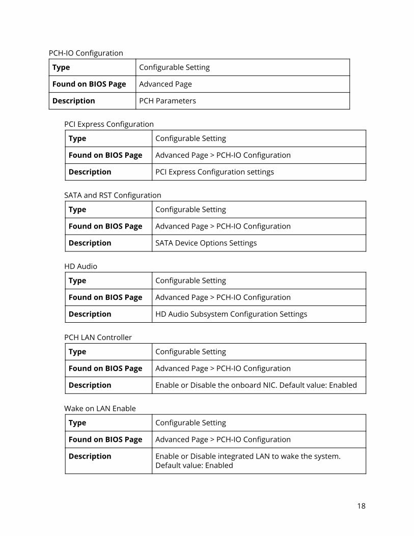
PCH-IO Configuration
Type Configurable Setting
Found on BIOS Page Advanced Page
Description PCH Parameters
PCI Express Configuration
Type Configurable Setting
Found on BIOS Page Advanced Page > PCH-IO Configuration
Description PCI Express Configuration settings
SATA and RST Configuration
Type Configurable Setting
Found on BIOS Page Advanced Page > PCH-IO Configuration
Description SATA Device Options Settings
HD Audio
Type Configurable Setting
Found on BIOS Page Advanced Page > PCH-IO Configuration
Description HD Audio Subsystem Configuration Settings
PCH LAN Controller
Type Configurable Setting
Found on BIOS Page Advanced Page > PCH-IO Configuration
Description Enable or Disable the onboard NIC. Default value: Enabled
Wake on LAN Enable
Type Configurable Setting
Found on BIOS Page Advanced Page > PCH-IO Configuration
Description Enable or Disable integrated LAN to wake the system. Default value: Enabled
18

SLP_LAN# Low on DC Power
Type Configurable Setting
Found on BIOS Page Advanced Page > PCH-IO Configuration
Description Enable or Disable SLP_LAN# Low on DC Power. Default value: Enabled
EFI Network
Type Configurable Setting
Found on BIOS Page Advanced Page > PCH-IO Configuration
Description Enable or Disable EFI Network support for onboard LAN or WiFi module. Possible values: Disabled / Onboard NIC / WiFi / Onboard NIC & WiFi. Default value: Disabled
Wake on WLAN and BT Enable
Type Configurable Setting
Found on BIOS Page Advanced Page > PCH-IO Configuration
Description Enable or Disable PCI Express Wireless LAN and Bluetooth to wake the system. Default value: Disabled
PXE ROM
Type Configurable Setting
Found on BIOS Page Advanced Page > PCH-IO Configuration
Description Enable or Disable PXE Option ROM execution. Default value: Disabled
19
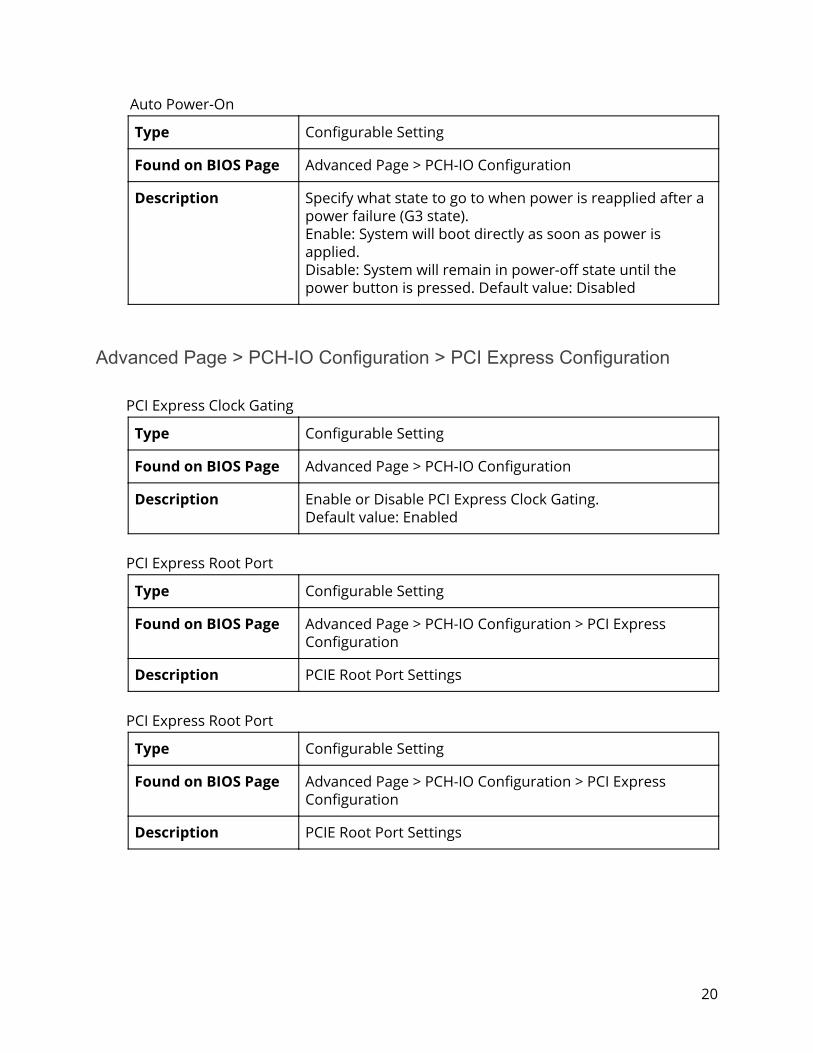
Auto Power-On
Type Configurable Setting
Found on BIOS Page Advanced Page > PCH-IO Configuration
Description Specify what state to go to when power is reapplied after a power failure (G3 state). Enable: System will boot directly as soon as power is applied. Disable: System will remain in power-off state until the power button is pressed. Default value: Disabled
Advanced Page > PCH-IO Configuration > PCI Express Configuration PCI Express Clock Gating
Type Configurable Setting
Found on BIOS Page Advanced Page > PCH-IO Configuration
Description Enable or Disable PCI Express Clock Gating. Default value: Enabled
PCI Express Root Port
Type Configurable Setting
Found on BIOS Page Advanced Page > PCH-IO Configuration > PCI Express Configuration
Description PCIE Root Port Settings
PCI Express Root Port
Type Configurable Setting
Found on BIOS Page Advanced Page > PCH-IO Configuration > PCI Express Configuration
Description PCIE Root Port Settings
20
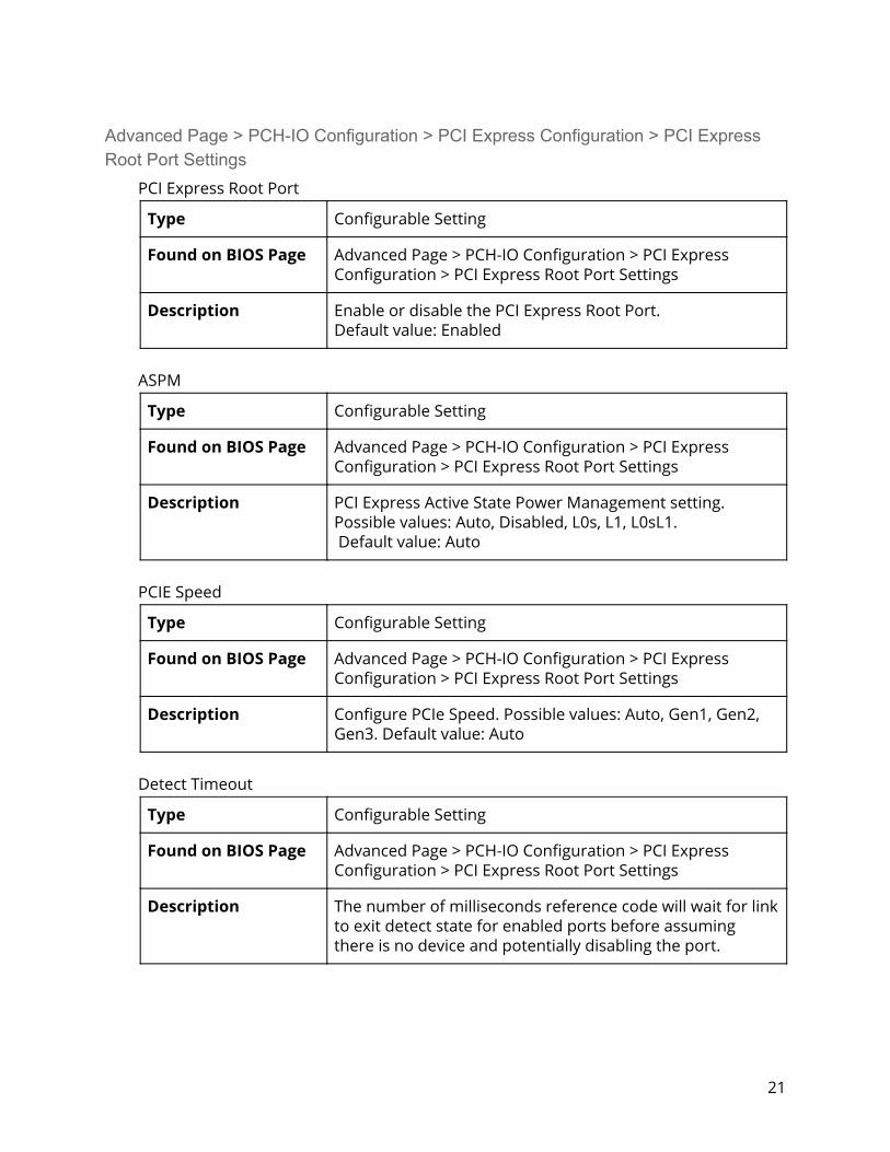
Advanced Page > PCH-IO Configuration > PCI Express Configuration > PCI Express Root Port Settings PCI Express Root Port
Type Configurable Setting
Found on BIOS Page Advanced Page > PCH-IO Configuration > PCI Express Configuration > PCI Express Root Port Settings
Description Enable or disable the PCI Express Root Port. Default value: Enabled
ASPM
Type Configurable Setting
Found on BIOS Page Advanced Page > PCH-IO Configuration > PCI Express Configuration > PCI Express Root Port Settings
Description PCI Express Active State Power Management setting. Possible values: Auto, Disabled, L0s, L1, L0sL1. Default value: Auto
PCIE Speed
Type Configurable Setting
Found on BIOS Page Advanced Page > PCH-IO Configuration > PCI Express Configuration > PCI Express Root Port Settings
Description Configure PCIe Speed. Possible values: Auto, Gen1, Gen2, Gen3. Default value: Auto
Detect Timeout
Type Configurable Setting
Found on BIOS Page Advanced Page > PCH-IO Configuration > PCI Express Configuration > PCI Express Root Port Settings
Description The number of milliseconds reference code will wait for link to exit detect state for enabled ports before assuming there is no device and potentially disabling the port.
21
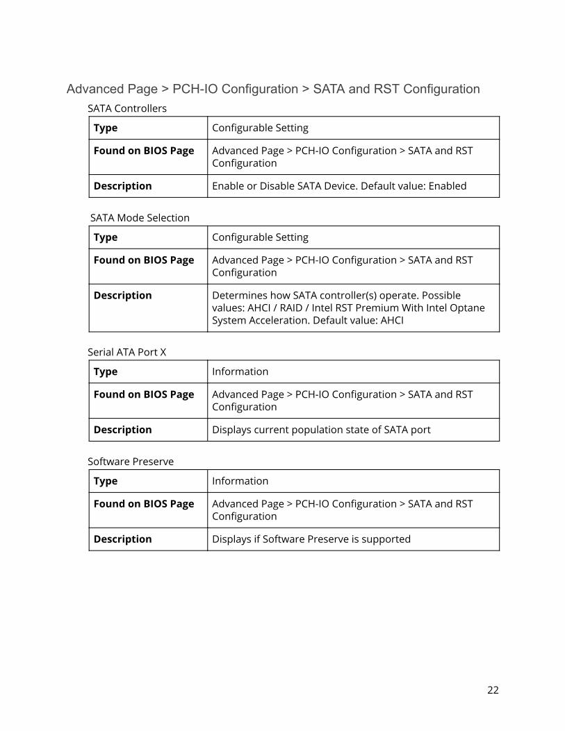
Advanced Page > PCH-IO Configuration > SATA and RST Configuration SATA Controllers
Type Configurable Setting
Found on BIOS Page Advanced Page > PCH-IO Configuration > SATA and RST Configuration
Description Enable or Disable SATA Device. Default value: Enabled
SATA Mode Selection
Type Configurable Setting
Found on BIOS Page Advanced Page > PCH-IO Configuration > SATA and RST Configuration
Description Determines how SATA controller(s) operate. Possible values: AHCI / RAID / Intel RST Premium With Intel Optane System Acceleration. Default value: AHCI
Serial ATA Port X
Type Information
Found on BIOS Page Advanced Page > PCH-IO Configuration > SATA and RST Configuration
Description Displays current population state of SATA port
Software Preserve
Type Information
Found on BIOS Page Advanced Page > PCH-IO Configuration > SATA and RST Configuration
Description Displays if Software Preserve is supported
22

Port X
Type Configurable Setting
Found on BIOS Page Advanced Page > PCH-IO Configuration > SATA and RST Configuration
Description Enable or Disable SATA Port. Default value: Enabled
Hot Plug
Type Configurable Setting
Found on BIOS Page Advanced Page > PCH-IO Configuration > SATA and RST Configuration
Description Designates this port as Hot Pluggable. Default value: Disabled
Configured as eSATA
Type Information
Found on BIOS Page Advanced Page > PCH-IO Configuration > SATA and RST Configuration
Description Displays configured as eSATA
External
Type Configurable Setting
Found on BIOS Page Advanced Page > PCH-IO Configuration > SATA and RST Configuration
Description Marks this port as external. Default value: Disabled
Spin Up Device
Type Configurable Setting
Found on BIOS Page Advanced Page > PCH-IO Configuration > SATA and RST Configuration
Description If enabled for any port, Staggered Spin Up will be performed and only the drives which have this option enabled will spin up at boot. Default value: Disabled
23

SATA Device Type
Type Configurable Setting
Found on BIOS Page Advanced Page > PCH-IO Configuration > SATA and RST Configuration
Description Identify if SATA port is connected to Solid State Drive or Hard Disk Drive. Possible values: Hard Disk Drive / Solid State Drive. Default value: Hard Disk Drive
Topology
Type Configurable Setting
Found on BIOS Page Advanced Page > PCH-IO Configuration > SATA and RST Configuration
Description Identify the SATA Topology if it is Default or ISATA or Flex or DirectConnect or M2.
Advanced Page > PCH-IO Configuration > HD Audio HD Audio
Type Configurable Setting
Found on BIOS Page Advanced Page > PCH-IO Configuration > HD Audio
Description Control Detection of the HD-Audio Device. Disabled = HDA will be unconditionally disabled. Enabled = HDA will be unconditionally enabled. Default value: Enabled
24
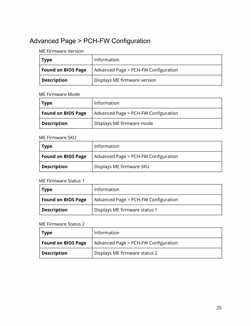
Advanced Page > PCH-FW Configuration ME Firmware Version
Type Information
Found on BIOS Page Advanced Page > PCH-FW Configuration
Description Displays ME firmware version
ME Firmware Mode
Type Information
Found on BIOS Page Advanced Page > PCH-FW Configuration
Description Displays ME firmware mode
ME Firmware SKU
Type Information
Found on BIOS Page Advanced Page > PCH-FW Configuration
Description Displays ME firmware SKU
ME Firmware Status 1
Type Information
Found on BIOS Page Advanced Page > PCH-FW Configuration
Description Displays ME firmware status 1
ME Firmware Status 2
Type Information
Found on BIOS Page Advanced Page > PCH-FW Configuration
Description Displays ME firmware status 2
25

ME State
Type Configurable Setting
Found on BIOS Page Advanced Page > PCH-FW Configuration
Description When Disabled ME will be put into ME Temporarily Disabled Mode. Default value: Enabled
Manageability Features State
Type Configurable Setting
Found on BIOS Page Advanced Page > PCH-FW Configuration
Description Enable or Disable Intel(R) Manageability features. Note: This option disables/enables Manageability Features support in FW. Platform must be in an unprovisioned state before disabling ME support. Default value: Enabled
AMT BIOS Features
Type Configurable Setting
Found on BIOS Page Advanced Page > PCH-FW Configuration
Description When disabled AMT BIOS Features are no longer supported and user is no longer able to access MEBx Setup. Note: This option does not disable Manageability Features in FW. Default value: Enabled
AMT Configuration
Type Configurable Setting
Found on BIOS Page Advanced Page > PCH-FW Configuration
Description Configure Intel(R) Active Management Technology Parameters
26
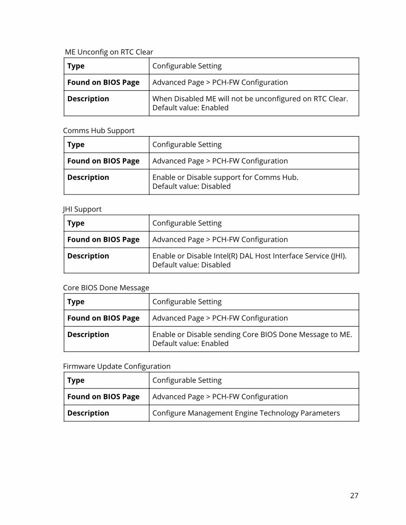
ME Unconfig on RTC Clear
Type Configurable Setting
Found on BIOS Page Advanced Page > PCH-FW Configuration
Description When Disabled ME will not be unconfigured on RTC Clear. Default value: Enabled
Comms Hub Support
Type Configurable Setting
Found on BIOS Page Advanced Page > PCH-FW Configuration
Description Enable or Disable support for Comms Hub. Default value: Disabled
JHI Support
Type Configurable Setting
Found on BIOS Page Advanced Page > PCH-FW Configuration
Description Enable or Disable Intel(R) DAL Host Interface Service (JHI). Default value: Disabled
Core BIOS Done Message
Type Configurable Setting
Found on BIOS Page Advanced Page > PCH-FW Configuration
Description Enable or Disable sending Core BIOS Done Message to ME. Default value: Enabled
Firmware Update Configuration
Type Configurable Setting
Found on BIOS Page Advanced Page > PCH-FW Configuration
Description Configure Management Engine Technology Parameters
27

PTT Configuration
Type Configurable Setting
Found on BIOS Page Advanced Page > PCH-FW Configuration
Description Configure PTT
Advanced Page > PCH-FW Configuration > AMT Configuration ASF Support
Type Configurable Setting
Found on BIOS Page Advanced Page > PCH-FW Configuration > ASF Support
Description Enable or Disable Alert Standard Format support. Default value: Enabled
USB Provisioning of AMT
Type Configurable Setting
Found on BIOS Page Advanced Page > PCH-FW Configuration > ASF Support
Description Enable or Disable AMT USB Provisioning. Default value: Disabled
CIRA Configuration
Type Configurable Setting
Found on BIOS Page Advanced Page > PCH-FW Configuration > ASF Support
Description Configure Remote Assistance Process parameters
ASF Configuration
Type Configurable Setting
Found on BIOS Page Advanced Page > PCH-FW Configuration > ASF Support
Description Configure Alert Standard Format parameters
28
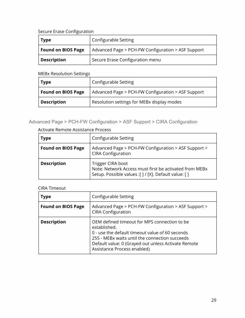
Secure Erase Configuration
Type Configurable Setting
Found on BIOS Page Advanced Page > PCH-FW Configuration > ASF Support
Description Secure Erase Configuration menu
MEBx Resolution Settings
Type Configurable Setting
Found on BIOS Page Advanced Page > PCH-FW Configuration > ASF Support
Description Resolution settings for MEBx display modes
Advanced Page > PCH-FW Configuration > ASF Support > CIRA Configuration Activate Remote Assistance Process
Type Configurable Setting
Found on BIOS Page Advanced Page > PCH-FW Configuration > ASF Support > CIRA Configuration
Description Trigger CIRA boot Note: Network Access must first be activated from MEBx Setup. Possible values :[ ] / [X]. Default value: [ ]
CIRA Timeout
Type Configurable Setting
Found on BIOS Page Advanced Page > PCH-FW Configuration > ASF Support > CIRA Configuration
Description OEM defined timeout for MPS connection to be established. 0 - use the default timeout value of 60 seconds 255 - MEBx waits until the connection succeeds Default value: 0 (Grayed out unless Activate Remote Assistance Process enabled )
29

Advanced Page > PCH-FW Configuration > ASF Support > ASF Configuration PET Progress
Type Configurable Setting
Found on BIOS Page Advanced Page > PCH-FW Configuration > ASF Support > ASF Configuration
Description Enable or Disable PET Events Progress to receive PET Events. Default value: Enabled
WatchDog
Type Configurable Setting
Found on BIOS Page Advanced Page > PCH-FW Configuration > ASF Support > ASF Configuration
Description Enable or Disable the WatchDog Timer. Default value: Disabled
OS Timer
Type Configurable Setting
Found on BIOS Page Advanced Page > PCH-FW Configuration > ASF Support > ASF Configuration
Description Set OS watchdog timer. Default value: 0 (Grayed out unless watchdog enabled)
BIOS Timer
Type Configurable Setting
Found on BIOS Page Advanced Page > PCH-FW Configuration > ASF Support > ASF Configuration
Description Set BIOS watchdog timer. Default value: 0 (Grayed out unless watchdog enabled)
30

ASF Sensors Table
Type Configurable Setting
Found on BIOS Page Advanced Page > PCH-FW Configuration > ASF Support > ASF Configuration
Description Adds ASF Sensor Table into ASF ACPI Table. Default value: Disabled
Advanced Page > PCH-FW Configuration > ASF Support > Secure Erase Configuration Secure Erase Mode
Type Configurable Setting
Found on BIOS Page Advanced Page > PCH-FW Configuration > ASF Support > Secure Erase Configuration
Description Change Secure Erase module behavior: Simulated: Performs SE flow without erasing SSD Real: Erase SSD Default value: Simulated
Force Secure Erase
Type Configurable Setting
Found on BIOS Page Advanced Page > PCH-FW Configuration > ASF Support > Secure Erase Configuration
Description Force Secure Erase on next boot. Default value: Disabled
31

Advanced Page > PCH-FW Configuration > ASF Support > MEBx Resolution Settings Non-UI Mode Resolution
Type Configurable Setting
Found on BIOS Page Advanced Page > PCH-FW Configuration > ASF Support > MEBx Resolution Settings
Description Resolution for non-UI text mode. Possible values: Auto / 80x25 / 100x31. Default value: Auto
UI Mode Resolution
Type Configurable Setting
Found on BIOS Page Advanced Page > PCH-FW Configuration > ASF Support > MEBx Resolution Settings
Description Resolution for UI text mode. Possible values: Auto / 80x25 / 100x31. Default value: Auto
Graphics Mode Resolution
Type Configurable Setting
Found on BIOS Page Advanced Page > PCH-FW Configuration > ASF Support > MEBx Resolution Settings
Description Resolution for graphics mode. Possible values: Auto / 640x480 / 800x600 / 1024x768. Default value: Auto
32
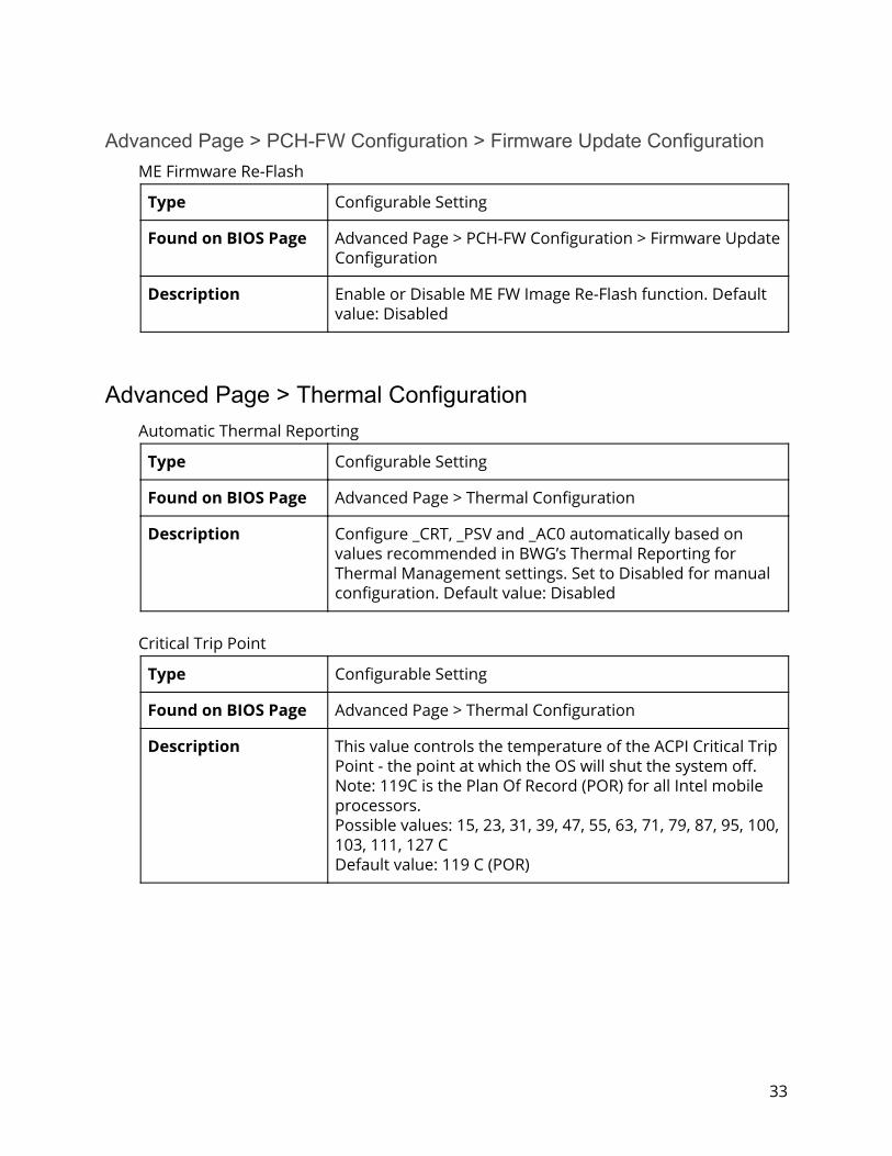
Advanced Page > PCH-FW Configuration > Firmware Update Configuration ME Firmware Re-Flash
Type Configurable Setting
Found on BIOS Page Advanced Page > PCH-FW Configuration > Firmware Update Configuration
Description Enable or Disable ME FW Image Re-Flash function. Default value: Disabled
Advanced Page > Thermal Configuration Automatic Thermal Reporting
Type Configurable Setting
Found on BIOS Page Advanced Page > Thermal Configuration
Description Configure _CRT, _PSV and _AC0 automatically based on values recommended in BWG’s Thermal Reporting for Thermal Management settings. Set to Disabled for manual configuration. Default value: Disabled
Critical Trip Point
Type Configurable Setting
Found on BIOS Page Advanced Page > Thermal Configuration
Description This value controls the temperature of the ACPI Critical Trip Point - the point at which the OS will shut the system off. Note: 119C is the Plan Of Record (POR) for all Intel mobile processors. Possible values: 15, 23, 31, 39, 47, 55, 63, 71, 79, 87, 95, 100, 103, 111, 127 C Default value: 119 C (POR)
33

Active Trip Point 0
Type Configurable Setting
Found on BIOS Page Advanced Page > Thermal Configuration
Description This value controls the temperature of the ACPI Active Trip Point 0 - the point at which the OS will set the processor fan to Active Trip Point 0 Fan Speed. Possible values: 15, 23, 31, 39, 47, 55, 63, 71, 79, 87, 95, 100, 111, 127 C Default value: 71 C
Active Trip Point 0 Fan Speed
Type Configurable Setting
Found on BIOS Page Advanced Page > Thermal Configuration
Description Active Trip Point 0 Fan Speed in percentage. Value must be between 0 (Fan off) - 100 (Max fan speed). This is the speed at which the fan will run when Active Trip Point 0 is crossed. Possible values: 0 - 100 Default value: 100
Active Trip Point 1
Type Configurable Setting
Found on BIOS Page Advanced Page > Thermal Configuration
Description This controls the temperature of the ACPI Active Trip Point 1 - the point at which the OS will set the processor fan to Active Trip Point 1 Fan Speed. Possible values: 15, 23, 31, 39, 47, 63, 71, 79, 87, 95, 100, 103, 111, 119 (POR), 127 C Default value: 55 C
34

Active Trip Point 1 Fan Speed
Type Configurable Setting
Found on BIOS Page Advanced Page > Thermal Configuration
Description Active Trip Point 1 Fan Speed in percentage. Value must be between 0 (Fan off) - 100 (Max fan speed). This value must be less than Active Trip Point 0 Fan Speed. This is the speed at which the fan will run when Active Trip 1 is crossed. Possible values: 0 - 100 Default value: 75
Passive Trip Point
Type Configurable Setting
Found on BIOS Page Advanced Page > Thermal Configuration
Description This value controls the temperature of the ACPI Passive Trip Point - the point in which the OS will begin throttling the processor. Possible values: 15, 23, 31, 39, 47, 55, 63, 71, 79, 87, 100, 103, 111, 119 (POR), 127 C Default value: 95 C
Passive TC1 Value
Type Configurable Setting
Found on BIOS Page Advanced Page > Thermal Configuration
Description This value sets the TC1 value for the ACPI Passive Cooling Formula. Range 1-16. Default value: 1
Passive TC2 Value
Type Configurable Setting
Found on BIOS Page Advanced Page > Thermal Configuration
Description This value sets the TC2 value for the ACPI Passive Cooling Formula. Range 1-16. Default value: 5
35

Passive TSP Value
Type Configurable Setting
Found on BIOS Page Advanced Page > Thermal Configuration
Description This item sets the TSP value for the ACPI Passive Cooling Formula. It represents in tenths of a second how often the OS will read the temperature when passive cooling is enabled. Range 2-32. Default value: 10
Active Trip Points
Type Configurable Setting
Found on BIOS Page Advanced Page > Thermal Configuration
Description Enable or Disable Active Trip Points. Default value: Enabled
Passive Trip Points
Type Configurable Setting
Found on BIOS Page Advanced Page > Thermal Configuration
Description Enable or Disable Passive Trip Points. Default value: Disabled
Critical Trip Points
Type Configurable Setting
Found on BIOS Page Advanced Page > Thermal Configuration
Description Enable or Disable Critical Trip Points. Default value: Enabled
Active Trip Points
Type Configurable Setting
Found on BIOS Page Advanced Page > Thermal Configuration
Description Enable or Disable Active Trip Points. Default value: Enabled
36

PCH Temp Read
Type Configurable Setting
Found on BIOS Page Advanced Page > Thermal Configuration
Description PCH Temperature Read Enable
CPU Energy Read
Type Configurable Setting
Found on BIOS Page Advanced Page > Thermal Configuration
Description CPU Energy Read Enable
CPU Temp Read
Type Configurable Setting
Found on BIOS Page Advanced Page > Thermal Configuration
Description CPU Temperature Read Enable
Alert Enable Lock
Type Configurable Setting
Found on BIOS Page Advanced Page > Thermal Configuration
Description Lock all Alert Enable Settings. Default value: Disabled
CPU Temp
Type Configurable Setting
Found on BIOS Page Advanced Page > Thermal Configuration
Description Fail Safe temp that EC will use if OS is hung. Default value: 75
CPU Fan Speed
Type Configurable Setting
Found on BIOS Page Advanced Page > Thermal Configuration
Description Fan speed that EC will use if OS is hung. Default value: 65
37

Advanced Page > SIO NCT5524D UART Port 1 Configuration
Type Configurable Setting
Found on BIOS Page Advanced Page > SIO NCT5524D Chip
Description UART configuration
UART Port 2 Configuration
Type Configurable Setting
Found on BIOS Page Advanced Page > SIO NCT5524D Chip
Description UART configuration
Fan Control
Type Configurable Setting
Found on BIOS Page Advanced Page > SIO NCT5524D Chip
Description Fan control configuration
Hardware Monitor
Type Configurable Setting
Found on BIOS Page Advanced Page > SIO NCT5524D Chip
Description Monitor all hardware sensors like voltage/temperature/fan speed
38
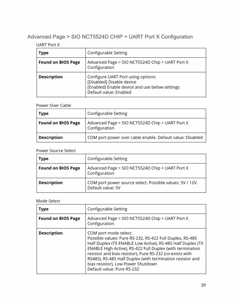
Advanced Page > SIO NCT5524D CHIP > UART Port X Configuration UART Port X
Type Configurable Setting
Found on BIOS Page Advanced Page > SIO NCT5524D Chip > UART Port X Configuration
Description Configure UART Port using options: [Disabled] Disable device [Enabled] Enable device and use below settings Default value: Enabled
Power Over Cable
Type Configurable Setting
Found on BIOS Page Advanced Page > SIO NCT5524D Chip > UART Port X Configuration
Description COM port power over cable enable. Default value: Disabled
Power Source Select
Type Configurable Setting
Found on BIOS Page Advanced Page > SIO NCT5524D Chip > UART Port X Configuration
Description COM port power source select. Possible values: 5V / 12V. Default value: 5V
Mode Select
Type Configurable Setting
Found on BIOS Page Advanced Page > SIO NCT5524D Chip > UART Port X Configuration
Description COM port mode select. Possible values: Pure RS-232, RS-422 Full Duplex, RS-485 Half Duplex (TX ENABLE Low Active), RS-485 Half Duplex (TX ENABLE High Active), RS-422 Full Duplex (with termination resistor and bias resistor), Pure RS-232 (co-exists with RS485), RS-485 Half Duplex (with termination resistor and bias resistor), Low Power Shutdown Default value: Pure RS-232
39

Advanced Page > SIO NCT5524D CHIP > Fan Control (Manual) SYSFANIN
Type Information
Found on BIOS Page Advanced Page > SIO NCT5524D Chip > Fan Control (Manual)
Description Displays current Fan RPM
CPUTIN
Type Information
Found on BIOS Page Advanced Page > SIO NCT5524D Chip > Fan Control (Manual)
Description Displays current CPU temperature
Mode
Type Configurable Setting
Found on BIOS Page Advanced Page > SIO NCT5524D Chip > Fan Control (Manual)
Description Choose Control Mode. Possible values: Manual, Thermal Cruise, Speed Cruise, Smart Fan IV. Default value: Manual
PWM/DC Output
Type Configurable Setting
Found on BIOS Page Advanced Page > SIO NCT5524D Chip > Fan Control (Manual)
Description Select fan output signal. Possible values: PWM Duty Cycle (%), DC Voltage (%). Default value: PWM Duty Cycle (%)
40

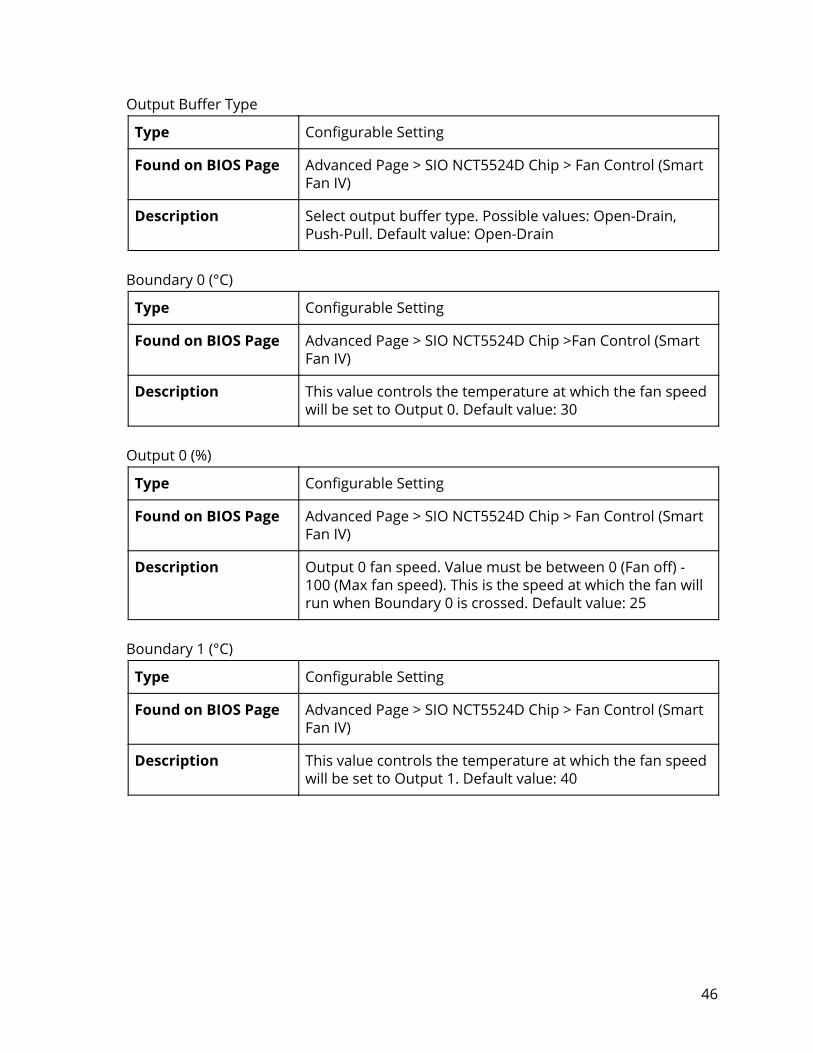
Output Buffer Type
Type Configurable Setting
Found on BIOS Page Advanced Page > SIO NCT5524D Chip > Fan Control (Manual)
Description Select output buffer type. Possible values: Open-Drain, Push-Pull. Default value: Open-Drain
PWM Duty Cycle (%) / DC Voltage (%) (Changes based on selected output mode)
Type Configurable Setting
Found on BIOS Page Advanced Page > SIO NCT5524D Chip > Fan Control (Manual)
Description Manually adjust PWM duty cycle [0-100]% / Manually adjust DC Voltage [0-100]%. Default value: 100
Advanced Page > SIO NCT5524D CHIP > Fan Control (Thermal Cruise) SYSFANIN
Type Information
Found on BIOS Page Advanced Page > SIO NCT5524D Chip > Fan Control (Thermal Cruise)
Description Displays current Fan RPM
CPUTIN
Type Information
Found on BIOS Page Advanced Page > SIO NCT5524D Chip > Fan Control (Thermal Cruise)
Description Displays current CPU temperature
41

Mode
Type Configurable Setting
Found on BIOS Page Advanced Page > SIO NCT5524D Chip > Fan Control (Thermal Cruise)
Description Choose Control Mode. Possible values: Manual, Thermal Cruise, Speed Cruise, Smart Fan IV. Default value: Manual
PWM/DC Output
Type Configurable Setting
Found on BIOS Page Advanced Page > SIO NCT5524D Chip > Fan Control (Thermal Cruise)
Description Select fan output signal. Possible values: PWM Duty Cycle (%), DC Voltage (%). Default value: PWM Duty Cycle (%)
Output Buffer Type
Type Configurable Setting
Found on BIOS Page Advanced Page > SIO NCT5524D Chip >Fan Control (Thermal Cruise)
Description Select output buffer type. Possible values: Open-Drain, Push-Pull. Default value: Open-Drain
Target Temperature (°C)
Type Configurable Setting
Found on BIOS Page Advanced Page > SIO NCT5524D Chip > Fan Control (Thermal Cruise)
Description The fan will try to maintain a temperature within Target Temperature ± Tolerance. Default value: 0
Tolerance (°C)
Type Configurable Setting
Found on BIOS Page Advanced Page > SIO NCT5524D Chip > Fan Control (Thermal Cruise)
Description Temperature tolerance. Default value: 0
42

Advanced Page > SIO NCT5524D CHIP > Fan Control (Speed Cruise) SYSFANIN
Type Information
Found on BIOS Page Advanced Page > SIO NCT5524D Chip > Fan Control (Speed Cruise)
Description Displays current Fan RPM
CPUTIN
Type Information
Found on BIOS Page Advanced Page > SIO NCT5524D Chip > Fan Control (Speed Cruise)
Description Displays current CPU temperature
Mode
Type Configurable Setting
Found on BIOS Page Advanced Page > SIO NCT5524D Chip > Fan Control (Speed Cruise)
Description Choose Control Mode. Possible values: Manual, Thermal Cruise, Speed Cruise, Smart Fan IV. Default value: Manual
PWM/DC Output
Type Configurable Setting
Found on BIOS Page Advanced Page > SIO NCT5524D Chip > Fan Control (Speed Cruise)
Description Select fan output signal. Possible values: PWM Duty Cycle (%), DC Voltage (%). Default value: PWM Duty Cycle (%)
43

Output Buffer Type
Type Configurable Setting
Found on BIOS Page Advanced Page > SIO NCT5524D Chip > Fan Control (Speed Cruise)
Description Select output buffer type. Possible values: Open-Drain, Push-Pull. Default value: Open-Drain
Target Fan Speed
Type Configurable Setting
Found on BIOS Page Advanced Page > SIO NCT5524D Chip > Fan Control (Speed Cruise)
Description The fan will try to keep the fan speed within Target Fan Speed ± Tolerance. When the fan speed is in this range, fan speed won’t change. If the fan speed is outside of this range, the fan will speed up or slow down toward the range. Default value: 0
Tolerance
Type Configurable Setting
Found on BIOS Page Advanced Page > SIO NCT5524D Chip > Fan Control (Speed Cruise)
Description Fan Speed Tolerance. Default value: 0
44

Advanced Page > SIO NCT5524D CHIP > Fan Control (Smart Fan IV) SYSFANIN
Type Information
Found on BIOS Page Advanced Page > SIO NCT5524D Chip > Fan Control (Smart Fan IV)
Description Displays current Fan RPM
CPUTIN
Type Information
Found on BIOS Page Advanced Page > SIO NCT5524D Chip > Fan Control (Smart Fan IV)
Description Displays current CPU temperature
Mode
Type Configurable Setting
Found on BIOS Page Advanced Page > SIO NCT5524D Chip > Fan Control (Smart Fan IV)
Description Choose Control Mode. Possible values: Manual, Thermal Cruise, Speed Cruise, Smart Fan IV. Default value: Manual
PWM/DC Output
Type Configurable Setting
Found on BIOS Page Advanced Page > SIO NCT5524D Chip > Fan Control (Smart Fan IV)
Description Select fan output signal. Possible values: PWM Duty Cycle (%), DC Voltage (%). Default value: PWM Duty Cycle (%)
45
Output Buffer Type
Type Configurable Setting
Found on BIOS Page Advanced Page > SIO NCT5524D Chip > Fan Control (Smart Fan IV)
Description Select output buffer type. Possible values: Open-Drain, Push-Pull. Default value: Open-Drain
Boundary 0 (°C)
Type Configurable Setting
Found on BIOS Page Advanced Page > SIO NCT5524D Chip >Fan Control (Smart Fan IV)
Description This value controls the temperature at which the fan speed will be set to Output 0. Default value: 30
Output 0 (%)
Type Configurable Setting
Found on BIOS Page Advanced Page > SIO NCT5524D Chip > Fan Control (Smart Fan IV)
Description Output 0 fan speed. Value must be between 0 (Fan off) - 100 (Max fan speed). This is the speed at which the fan will run when Boundary 0 is crossed. Default value: 25
Boundary 1 (°C)
Type Configurable Setting
Found on BIOS Page Advanced Page > SIO NCT5524D Chip > Fan Control (Smart Fan IV)
Description This value controls the temperature at which the fan speed will be set to Output 1. Default value: 40
46
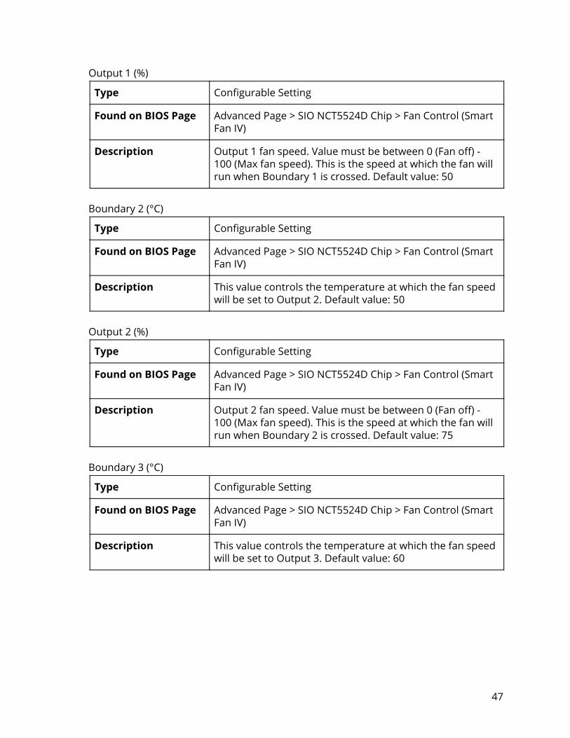
Output 1 (%)
Type Configurable Setting
Found on BIOS Page Advanced Page > SIO NCT5524D Chip > Fan Control (Smart Fan IV)
Description Output 1 fan speed. Value must be between 0 (Fan off) - 100 (Max fan speed). This is the speed at which the fan will run when Boundary 1 is crossed. Default value: 50
Boundary 2 (°C)
Type Configurable Setting
Found on BIOS Page Advanced Page > SIO NCT5524D Chip > Fan Control (Smart Fan IV)
Description This value controls the temperature at which the fan speed will be set to Output 2. Default value: 50
Output 2 (%)
Type Configurable Setting
Found on BIOS Page Advanced Page > SIO NCT5524D Chip > Fan Control (Smart Fan IV)
Description Output 2 fan speed. Value must be between 0 (Fan off) - 100 (Max fan speed). This is the speed at which the fan will run when Boundary 2 is crossed. Default value: 75
Boundary 3 (°C)
Type Configurable Setting
Found on BIOS Page Advanced Page > SIO NCT5524D Chip > Fan Control (Smart Fan IV)
Description This value controls the temperature at which the fan speed will be set to Output 3. Default value: 60
47
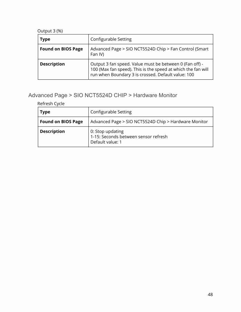
Output 3 (%)
Type Configurable Setting
Found on BIOS Page Advanced Page > SIO NCT5524D Chip > Fan Control (Smart Fan IV)
Description Output 3 fan speed. Value must be between 0 (Fan off) - 100 (Max fan speed). This is the speed at which the fan will run when Boundary 3 is crossed. Default value: 100
Advanced Page > SIO NCT5524D CHIP > Hardware Monitor Refresh Cycle
Type Configurable Setting
Found on BIOS Page Advanced Page > SIO NCT5524D Chip > Hardware Monitor
Description 0: Stop updating 1-15: Seconds between sensor refresh Default value: 1
48

Security Page Current TPM Device
Type Information
Found on BIOS Page Security Page
Description Displays current TPM device
TPM State
Type Information
Found on BIOS Page Security Page
Description Displays current TPM state
TPM Active PCR Hash Algorithm
Type Information
Found on BIOS Page Security Page
Description Displays active PCR hash algorithm
TPM Hardware Supported Hash Algorithm
Type Information
Found on BIOS Page Security Page
Description Displays hardware supported hash algorithm
BIOS Supported Hash Algorithm
Type Information
Found on BIOS Page Security Page
Description Displays BIOS supported hash algorithm
49

TrEE Protocol Version
Type Configurable Setting
Found on BIOS Page Security Page
Description Select TrEE Protocol Version: 1.0 or 1.1. Possible values: 1.1, 1.0. Default value: 1.1
TPM Availability
Type Configurable Setting
Found on BIOS Page Security Page
Description When Hidden, don’t exposes TPM to 0. Possible values: Available/Hidden. Default value: Available
TPM Operation
Type Configurable Setting
Found on BIOS Page Security Page
Description Select one of the supported operation to change TPM2 state. Possible values: Enable, SetPCRBanks(Algorithm), LogAllDigests, SetPPRequiredForClear_True, SetPPRequiredForClear_False, SetPPRequiredForTurnOn_False, SetPPRequiredForTurnOn_True, SetPPRequiredForTurnOff_False, SetPPRequiredForTurnOff_True, SetPPRequiredForChangePCRs_False, SetPPRequriedForChangePCRs_True, SetPPRequiredForChangeEPS_False, SetPPRequiredForChangeEPS_True, ChangeEPS Default value: No Operation
Clear TPM
Type Configurable Setting
Found on BIOS Page Security Page
Description Remove all TPM context associated with a specific owner.
50
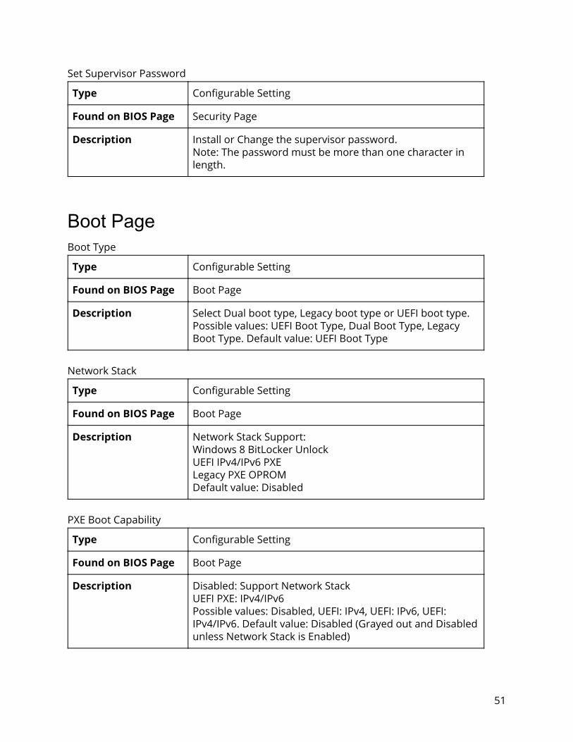
Set Supervisor Password
Type Configurable Setting
Found on BIOS Page Security Page
Description Install or Change the supervisor password. Note: The password must be more than one character in length.
Boot Page Boot Type
Type Configurable Setting
Found on BIOS Page Boot Page
Description Select Dual boot type, Legacy boot type or UEFI boot type. Possible values: UEFI Boot Type, Dual Boot Type, Legacy Boot Type. Default value: UEFI Boot Type
Network Stack
Type Configurable Setting
Found on BIOS Page Boot Page
Description Network Stack Support: Windows 8 BitLocker Unlock UEFI IPv4/IPv6 PXE Legacy PXE OPROM Default value: Disabled
PXE Boot Capability
Type Configurable Setting
Found on BIOS Page Boot Page
Description Disabled: Support Network Stack UEFI PXE: IPv4/IPv6 Possible values: Disabled, UEFI: IPv4, UEFI: IPv6, UEFI: IPv4/IPv6. Default value: Disabled (Grayed out and Disabled unless Network Stack is Enabled)
51

Add Boot Options
Type Configurable Setting
Found on BIOS Page Boot Page
Description Position in Boot Order for Shell, Network, and Removables. Possible values: First, Last. Default value: First
USB Boot
Type Configurable Setting
Found on BIOS Page Boot Page
Description Disables or enables booting to USB boot devices. Default value: Enabled
UEFI OS Fast Boot
Type Configurable Setting
Found on BIOS Page Boot Page
Description If enabled the system firmware does not initialize keyboard and check for firmware menu key. Default value: Enabled
EFI
Type Configurable Setting
Found on BIOS Page Boot Page
Description EFI Boot Order Settings
52
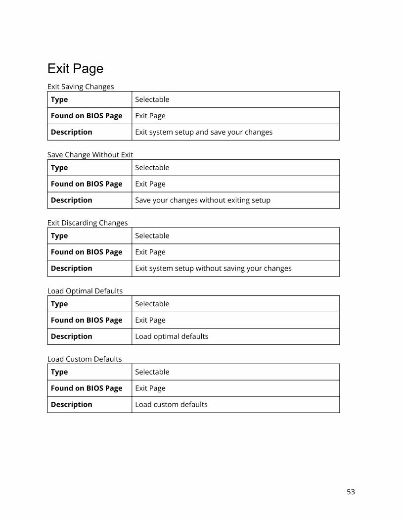
Exit Page Exit Saving Changes
Type Selectable
Found on BIOS Page Exit Page
Description Exit system setup and save your changes
Save Change Without Exit
Type Selectable
Found on BIOS Page Exit Page
Description Save your changes without exiting setup
Exit Discarding Changes
Type Selectable
Found on BIOS Page Exit Page
Description Exit system setup without saving your changes
Load Optimal Defaults
Type Selectable
Found on BIOS Page Exit Page
Description Load optimal defaults
Load Custom Defaults
Type Selectable
Found on BIOS Page Exit Page
Description Load custom defaults
53

Save Custom Defaults
Type Selectable
Found on BIOS Page Exit Page
Description Save custom defaults
Discard Changes
Type Selectable
Found on BIOS Page Exit Page
Description Discard changes
54


![Software Reference GuideBIOS image 1. BIOS BIOS image xxxxxxxx. rom 2. ASUS Utility] WINFLASH] WINFLASH V2.08] WINFLASH V2. 08 BIOS. 14 1-5 BIOS ( WINFLASH) 7. Exit BIOS 8.](https://static.documents.pub/doc/80x56/5f7bf64501fae364dd7d788d/software-reference-guide-bios-image-1-bios-bios-image-xxxxxxxx-rom-2-asus-utility.jpg)


