• Torque screwdriver, set to 18 Ncm ± 6%. Bits 6, NTZ 112 288
• Flex film assembly tool NTZ 112 521
• Blunt pair of tweezers, pair of tweezers
• Screwdriver, width 3 mm
• K700i/Front opening tool NTZ 112 540
• Front opening tool NTZ 112 302/2
• Dentist hook
Equipment
• ESD-gloves (cotton gloves)
• ESD-wristband
Instruction
• Keep all contact surfaces clean of dirt and hand-grease
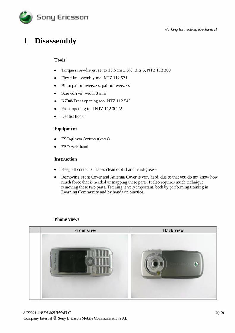
• Removing Front Cover and Antenna Cover is very hard, due to that you do not know how much force that is needed unsnapping these parts. It also requires much technique removing these two parts. Training is very important, both by performing training in Learning Community and by hands on practice.
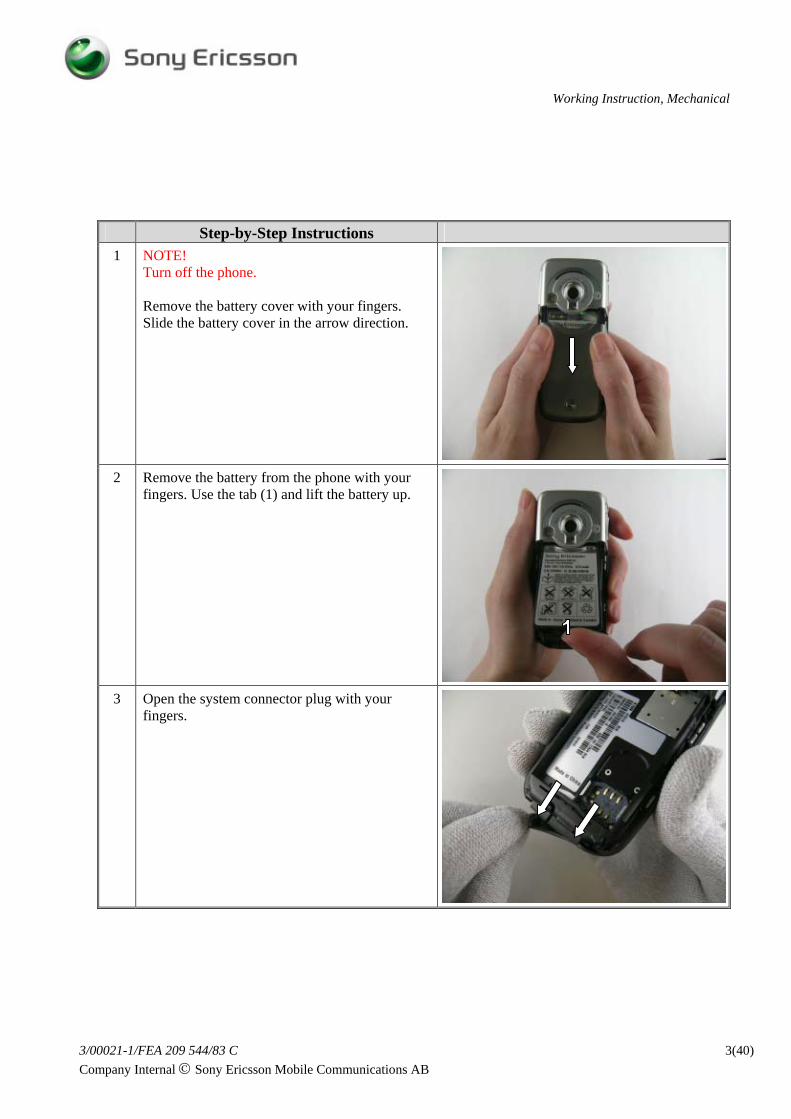
Step-by-Step Instructions 4 Separating front from frame:
1A-1B hooks: Put the phone on a flat, clean surface. First release hooks 1A and 1B close to the system connector. Use a screwdriver, width 3 mm. NOTE! ESD gloves must not be used when separating snap fit hooks. Be careful when using the screwdriver, hooks are tight fitted and you may easily slip and injure your fingers. Also be careful not to scratch the frame and damage front hooks with the screwdriver. Put Place the screwdriver in the slot (1B). Press directly down hard to release the snap fit hook. Do the same on the opposite side. The phone should be placed on a flat, clean surface during the releasing of 1A -1B hooks. NOTE! Do not use any tool or your nail to separate front from frame, front will easily get scratched. The only way to separate front from frame is to release hooks according to the instruction.
The screwdriver should be in 90 degrees angle when releasing the bottom front snap fit hooks. NOTE! When removing the front cover the first time, it is hard to predict the amount of force needed. Usually it requires more force then you think.Pushing of 1A & 1B is the hardest part! When the two bottom hooks are released a small gap is seen between front and frame.
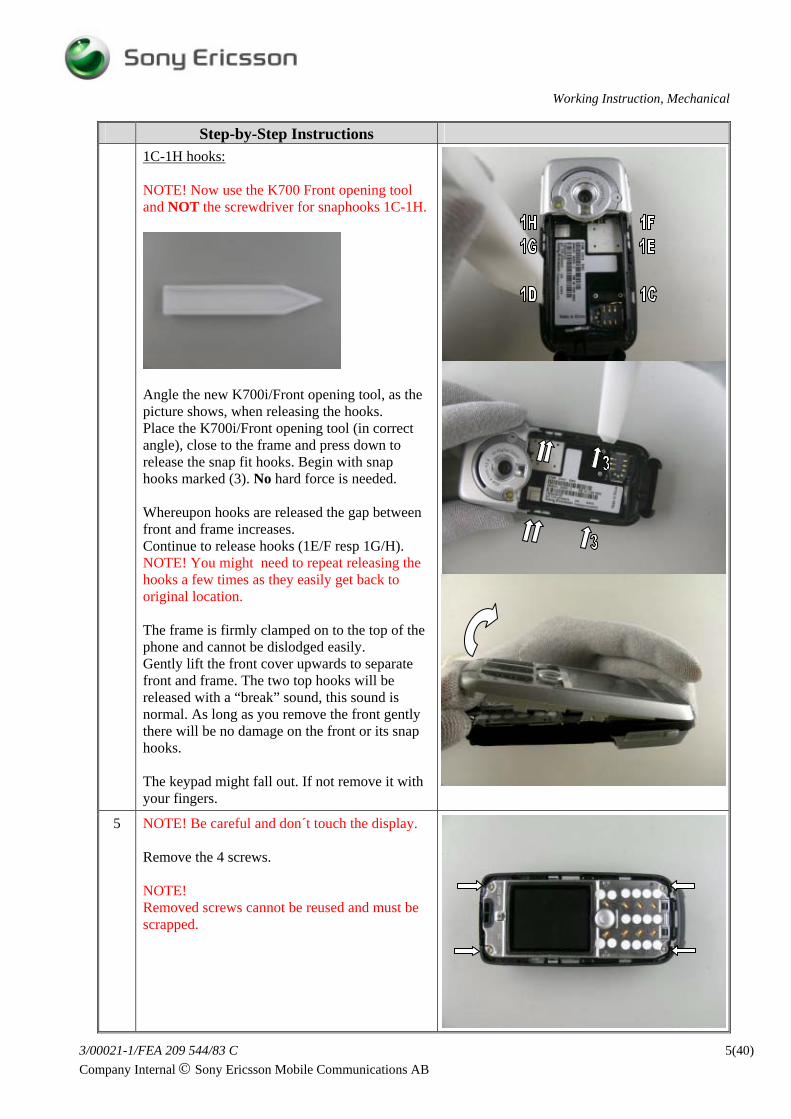
NOTE! Now use the K700 Front opening tool and NOT the screwdriver for snaphooks 1C-1H.
Angle the new K700i/Front opening tool, as the picture shows, when releasing the hooks. Place the K700i/Front opening tool (in correct angle), close to the frame and press down to release the snap fit hooks. Begin with snap hooks marked (3). No hard force is needed. Whereupon hooks are released the gap between front and frame increases. Continue to release hooks (1E/F resp 1G/H). NOTE! You might need to repeat releasing the hooks a few times as they easily get back to original location. The frame is firmly clamped on to the top of the phone and cannot be dislodged easily. Gently lift the front cover upwards to separate front and frame. The two top hooks will be released with a “break” sound, this sound is normal. As long as you remove the front gently there will be no damage on the front or its snap hooks. The keypad might fall out. If not remove it with your fingers.
5 NOTE! Be careful and don´t touch the display. Remove the 4 screws. NOTE! Removed screws cannot be reused and must be scrapped.
Step-by-Step Instructions 6 Remove the joystick button with your fingers.
NOTE! The joystick may be tight fitted to the switch.
7 Use front opening tool to separate the metal carrier from the frame. Two frame snap fit hooks, located in the middle section, shall be released. Place the opening tool close to the metal carrier and press down until the hook moves to the frame wall (1). Angle the opening tool, as the picture shows (2), until the metal carrier is released. Do the same on the opposite side of the metal carrier. Remove the metal carrier. The system connector plug will most likely fall out when releasing the metal carrier (3). If not remove the plug.
Do not touch the display glass with your fingers. Lift the display with your fingers. NOTE! Be careful not to damage the display flexfilm with the tweezers. Remove the connector tape with a blunt pair of tweezers. NOTE! Removed tape cannot be reused and must be scrapped. NOTE! Be careful not to damage the FPC connector clamp with the tweezers. Open the FPC connector with a pair of tweezers.
NOTE! Be careful with the display flexfilm. Remove the display assembly from the FPC connector with the flex film assembly tool.
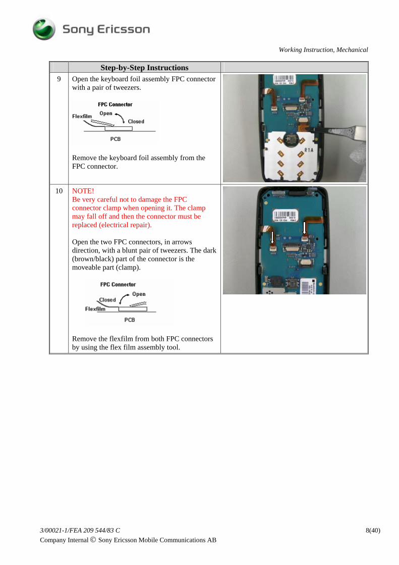
Step-by-Step Instructions 9 Open the keyboard foil assembly FPC connector
with a pair of tweezers.
Remove the keyboard foil assembly from the FPC connector.
10 NOTE! Be very careful not to damage the FPC connector clamp when opening it. The clamp may fall off and then the connector must be replaced (electrical repair). Open the two FPC connectors, in arrows direction, with a blunt pair of tweezers. The dark (brown/black) part of the connector is the moveable part (clamp).
Remove the flexfilm from both FPC connectors by using the flex film assembly tool.
PCB and frame are connected by camera flexfilm. Release the PCB from the frame by overturning the frame as the picture shows. NOTE! Be careful with the tweezers and do not damage the board-to-board connector. Disconnect the camera flexfilm board-to-board connector by lifting upwards with the flex film assembly tool. Front, frame and PCB disassembled.
NOTE! The antenna cover should only be removed if there is a need of replacing the antenna cover itself, the frame or any of the following components located underneath the antenna cover: Volume and camera keys Internet access key Antenna flex Flexfilm volume and camera key Flexfilm camera light assembly Camera (for verifying that the camera is fitted properly) There is no need to remove the external antenna connector plug. Use a dentist hook or a flat screwdriver to remove the antenna cover. As long as you do not scratch the antenna cover or frame, you can use the tool that you feel most comfortable with. If you use a sharp tool be careful not to damage the snap hook. When removing the antenna cover the first time it is hard to predict the amount of force needed. Usually, as when removing the front cover, it requires more force then you think. If the phone is already disassembled, and there is a need for removing the antenna cover, it is OK to unsnap the antenna cover snap hooks from the inside.
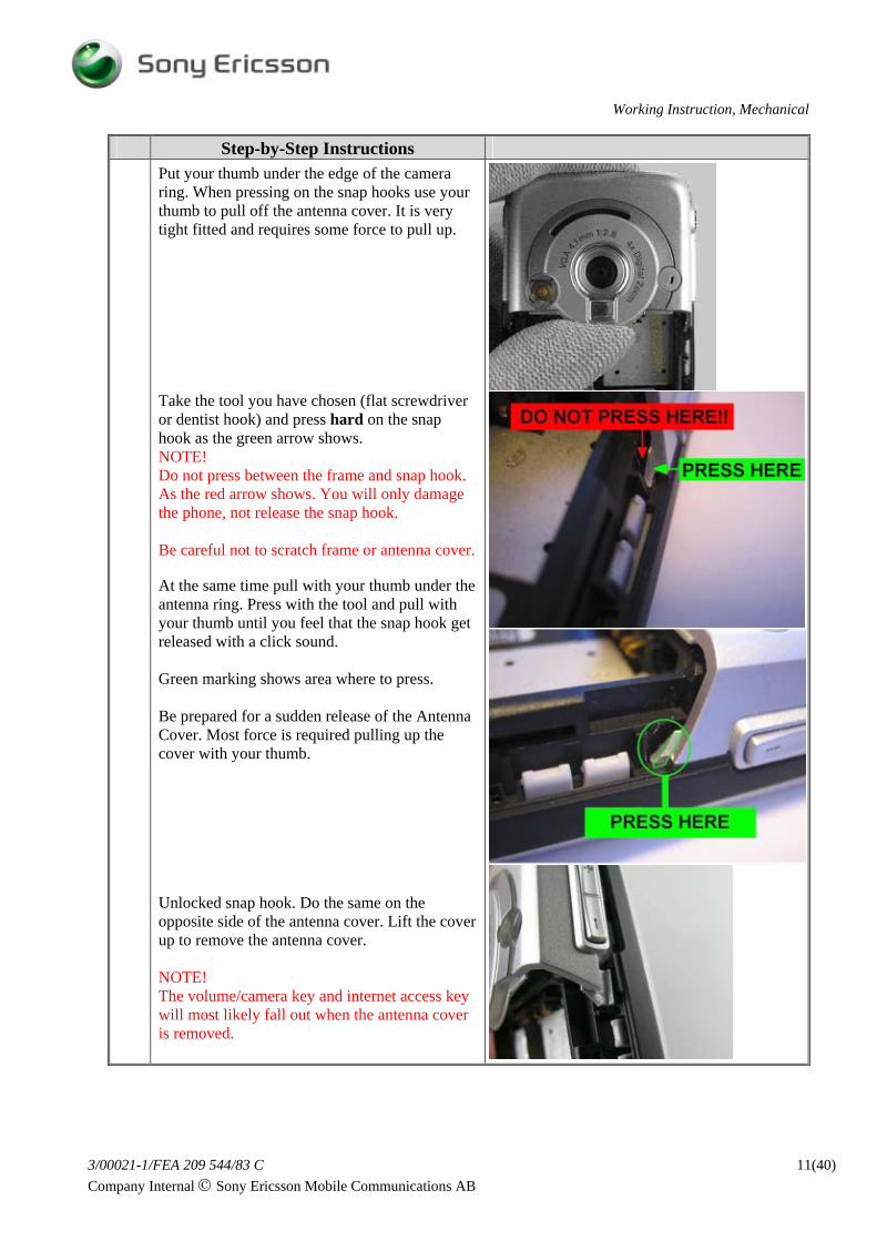
Step-by-Step Instructions Put your thumb under the edge of the camera
ring. When pressing on the snap hooks use your thumb to pull off the antenna cover. It is very tight fitted and requires some force to pull up. Take the tool you have chosen (flat screwdriver or dentist hook) and press hard on the snap hook as the green arrow shows. NOTE! Do not press between the frame and snap hook. As the red arrow shows. You will only damage the phone, not release the snap hook. Be careful not to scratch frame or antenna cover. At the same time pull with your thumb under the antenna ring. Press with the tool and pull with your thumb until you feel that the snap hook get released with a click sound. Green marking shows area where to press. Be prepared for a sudden release of the Antenna Cover. Most force is required pulling up the cover with your thumb. Unlocked snap hook. Do the same on the opposite side of the antenna cover. Lift the cover up to remove the antenna cover. NOTE! The volume/camera key and internet access key will most likely fall out when the antenna cover is removed.
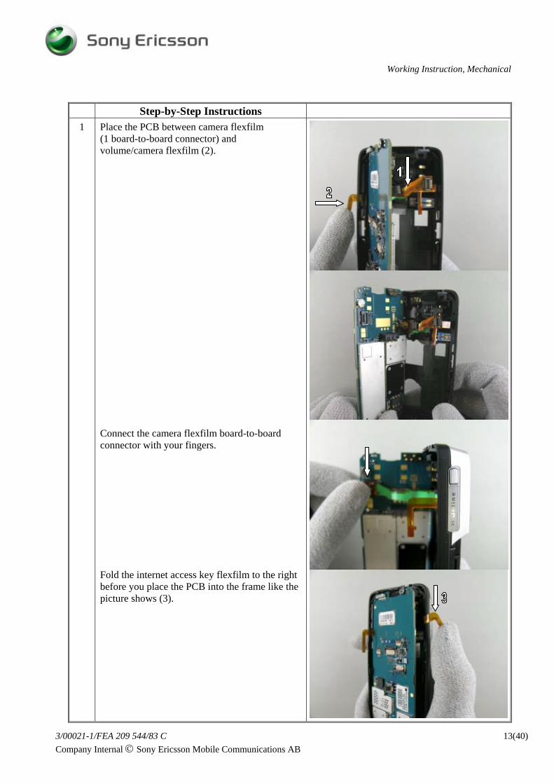
Step-by-Step Instructions 1 Place the PCB between camera flexfilm
(1 board-to-board connector) and volume/camera flexfilm (2). Connect the camera flexfilm board-to-board connector with your fingers. Fold the internet access key flexfilm to the right before you place the PCB into the frame like the picture shows (3).
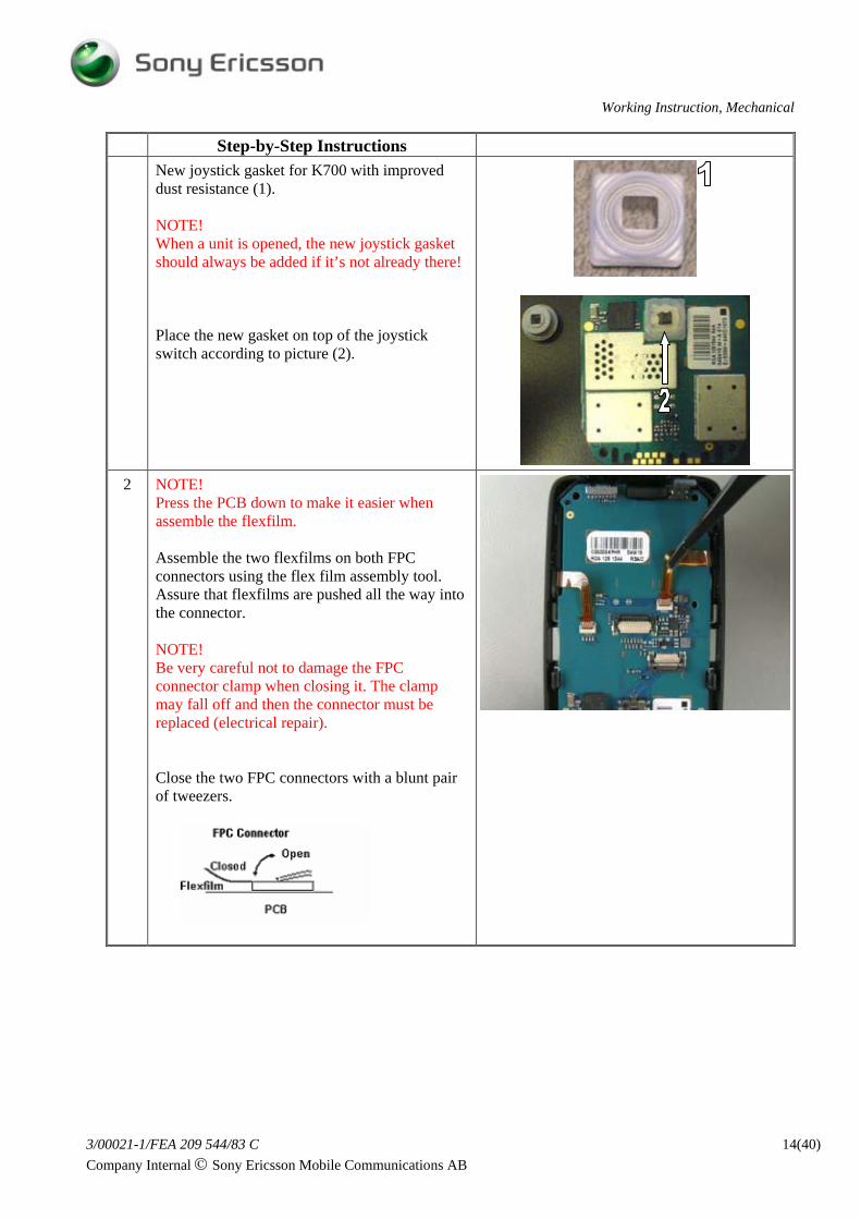
Step-by-Step Instructions New joystick gasket for K700 with improved
dust resistance (1). NOTE! When a unit is opened, the new joystick gasket should always be added if it’s not already there! Place the new gasket on top of the joystick switch according to picture (2).
2 NOTE!
Press the PCB down to make it easier when assemble the flexfilm. Assemble the two flexfilms on both FPC connectors using the flex film assembly tool. Assure that flexfilms are pushed all the way into the connector. NOTE! Be very careful not to damage the FPC connector clamp when closing it. The clamp may fall off and then the connector must be replaced (electrical repair). Close the two FPC connectors with a blunt pair of tweezers.
Step-by-Step Instructions 3 Assemble the keyboard foil flexfilm into the
FPC connector. Use flex film assembly tool. Close the FPC connector with a blunt pair of tweezers.
Press down the keyboard foil close to the system connector.
4 Assemble the system connector plug. Align the two tabs (1). Press on the plug as the picture shows (2) to assure that the system connector plug is placed in the recess. NOTE! Assure that system connector plug is properly fitted close to the frame before assembling metal carrier and front.
Do not touch the display glass with your fingers. Assemble the display flexfilm into the FPC connector. Use the flex film assembly tool. Close the FPC connector with a blunt pair of tweezers.
Assemble a new connector tape over the display and keyboard foil connectors. Gently fold the display to the proper position by using the frame guiding pin and press with your fingers. NOTE! If you have assembled a new display: Remember to remove the display protection foil with a pair of tweezers before assembling the metal carrier.
Step-by-Step Instructions 6 Place the metal carrier over the frame assembly.
Assure that system connector plug latches are under the frame (1). Place the front opening tool close to the metal carrier (2) and press down until the frame hook fastens the metal carrier with a “click” sound. Use the white display-guiding pin (3 close to screw opening) to get the metal carrier in the correct position. Do the same on the opposite side of the metal carrier (4). Press on the phone, as the picture shows, to assure that the hooks are properly fitted into the metal carrier. NOTE! Another “click” sound might be heard.
7 Press the joystick assembly onto the joystick switch pin. NOTE! If you reused the old joystick and have mounted the new Joystick Gasket: Remember to remove the black/grey joystick dust gasket.
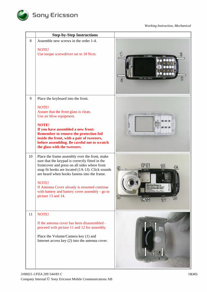
Step-by-Step Instructions 8 Assemble new screws in the order 1-4.
NOTE! Use torque screwdriver set to 18 Ncm.
9 Place the keyboard into the front. NOTE! Assure that the front glass is clean. Use air blow equipment. NOTE! If you have assembled a new front: Remember to remove the protection foil inside the front, with a pair of tweezers, before assembling. Be careful not to scratch the glass with the tweezers.
10 Place the frame assembly over the front, make sure that the keypad is correctly fitted in the frontcover and press on all sides where front snap fit hooks are located (1A-1J). Click sounds are heard when hooks fastens into the frame. NOTE! If Antenna Cover already is mounted continue with battery and battery cover assembly - go to picture 13 and 14.
11 NOTE! If the antenna cover has been disassembled - proceed with picture 11 and 12 for assembly. Place the Volume/Camera key (1) and Internet access key (2) into the antenna cover.
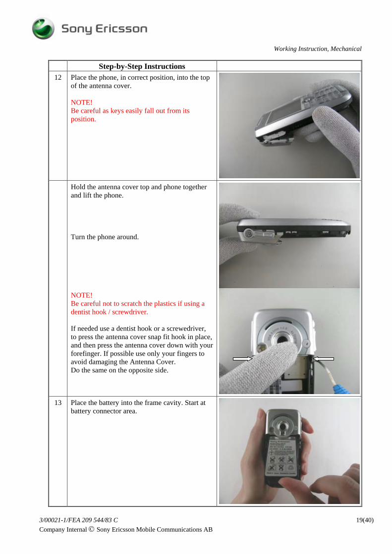
Step-by-Step Instructions 12 Place the phone, in correct position, into the top
of the antenna cover. NOTE! Be careful as keys easily fall out from its position.
Hold the antenna cover top and phone together and lift the phone. Turn the phone around. NOTE! Be careful not to scratch the plastics if using a dentist hook / screwdriver. If needed use a dentist hook or a screwedriver, to press the antenna cover snap fit hook in place, and then press the antenna cover down with your forefinger. If possible use only your fingers to avoid damaging the Antenna Cover. Do the same on the opposite side.
13 Place the battery into the frame cavity. Start at battery connector area.
Step-by-Step Instructions 14 Slide the battery cover, in the arrow direction,
onto the phone.
3 Replacement of Mechanical Parts
Equipment
• ESD-gloves (cotton gloves)
• ESD-wristband
Instruction
• Keep all contact surfaces clean of dirt and hand-grease
3.1 System Connector Replacement of System Connector: Check end of Disassembly and Reassembly headings. Draw attention to Note comments.
3.2 Antenna Cover Complete Replacement of antenna cover complete: Check end of Disassembly and Reassembly headings. Draw attention to Note comments.
3.3 Volume/Camera Keys & Internet Access Key Replacement of volume/camera keys & Internet access key: Check end of Disassembly and Reassembly headings. Draw attention to Note comments.
3.4 Front Complete Replacement of front complete: Check Disassembly and Reassembly headings and draw attention to Note comments.
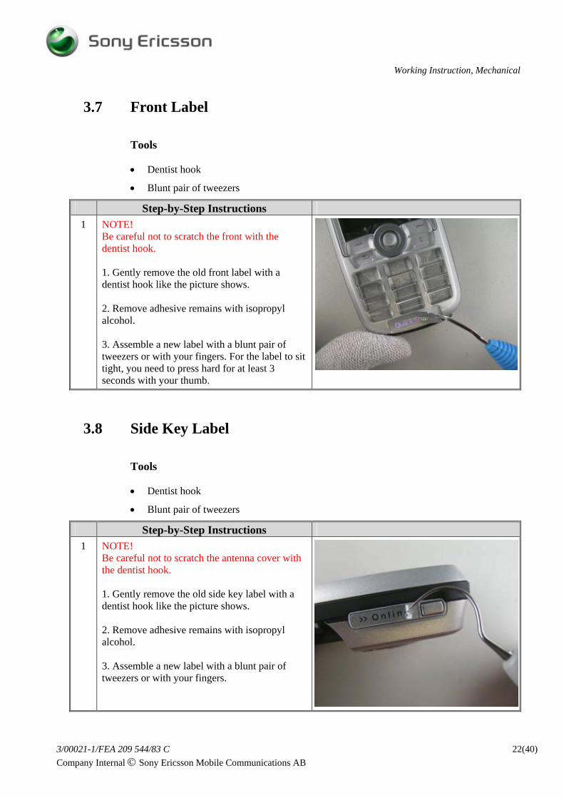
Be careful not to scratch the front with the dentist hook. 1. Gently remove the old front label with a dentist hook like the picture shows. 2. Remove adhesive remains with isopropyl alcohol. 3. Assemble a new label with a blunt pair of tweezers or with your fingers. For the label to sit tight, you need to press hard for at least 3 seconds with your thumb.
3.8 Side Key Label
Tools
• Dentist hook
• Blunt pair of tweezers
Step-by-Step Instructions 1 NOTE!
Be careful not to scratch the antenna cover with the dentist hook. 1. Gently remove the old side key label with a dentist hook like the picture shows. 2. Remove adhesive remains with isopropyl alcohol. 3. Assemble a new label with a blunt pair of tweezers or with your fingers.
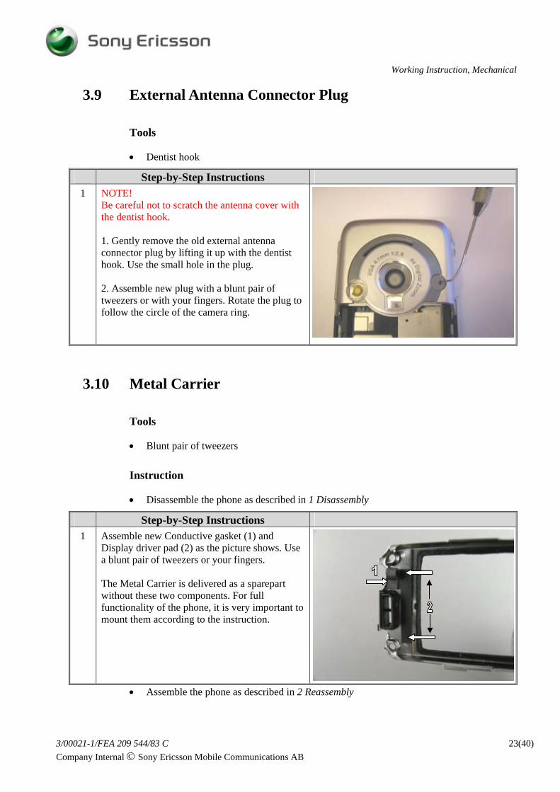
Be careful not to scratch the antenna cover with the dentist hook. 1. Gently remove the old external antenna connector plug by lifting it up with the dentist hook. Use the small hole in the plug. 2. Assemble new plug with a blunt pair of tweezers or with your fingers. Rotate the plug to follow the circle of the camera ring.
3.10 Metal Carrier
Tools
• Blunt pair of tweezers
Instruction
• Disassemble the phone as described in 1 Disassembly
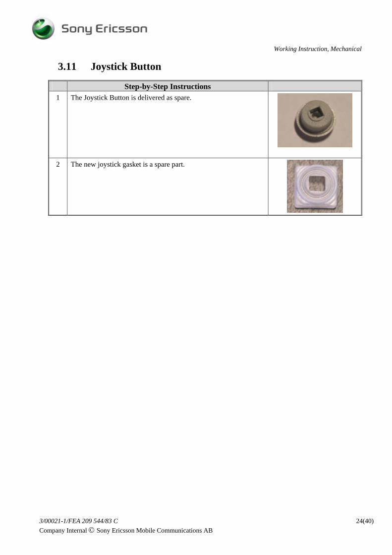
Step-by-Step Instructions 1 Assemble new Conductive gasket (1) and
Display driver pad (2) as the picture shows. Use a blunt pair of tweezers or your fingers. The Metal Carrier is delivered as a sparepart without these two components. For full functionality of the phone, it is very important to mount them according to the instruction.
• Disassemble the phone, including the antenna cover, as described in 1 Disassembly
Step-by-Step Instructions 1 NOTE!
Notice the antenna flexfilm position before removal. Remove the antenna flexfilm from the frame with a pair of tweezers or with your fingers. Remove adhesive remains with isopropyl alcohol.
Step-by-Step Instructions 2 Peel off the protection foil from the antenna
contact pads. Locate the antenna flex into the frame opening and fasten it on the frame (1). Remove the rest of the protection foil, fold the flexfilm and fasten it on the frame with your thumbs.
• Disassemble the phone, including the antenna cover, as described in 1 Disassembly
Step-by-Step Instructions 1 NOTE!
Notice the flexfilm position before removal. Remove the volume and camera key flexfilm from the frame with a dentist hook. Remove adhesive remains with isopropyl alcohol.
2 Put the flexfilm through the opening in the frame (1). Peel off the protection foil and place the domefoil close to the frame wall (2). Fasten the domefoil inside the support edges (3).
• Disassemble the phone, including the antenna cover, as described in 1 Disassembly
Step-by-Step Instructions 1 NOTE!
Notice the flexfilm position before removal. Remove the camera light assembly flexfilm from the frame with a dentist hook. Continue to remove the flexfilm with your fingers. Remove adhesive remains with isopropyl alcohol.
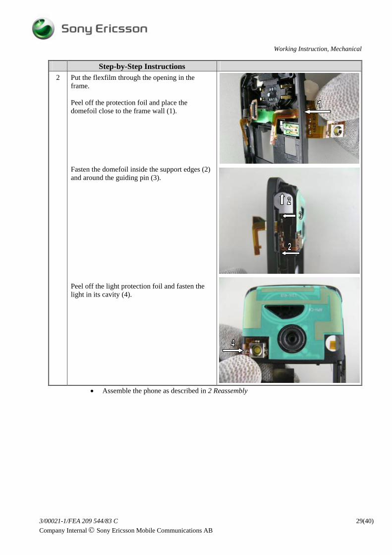
Step-by-Step Instructions 2 Put the flexfilm through the opening in the
frame. Peel off the protection foil and place the domefoil close to the frame wall (1). Fasten the domefoil inside the support edges (2) and around the guiding pin (3). Peel off the light protection foil and fasten the light in its cavity (4).
• Disassemble the phone as described in 1 Disassembly
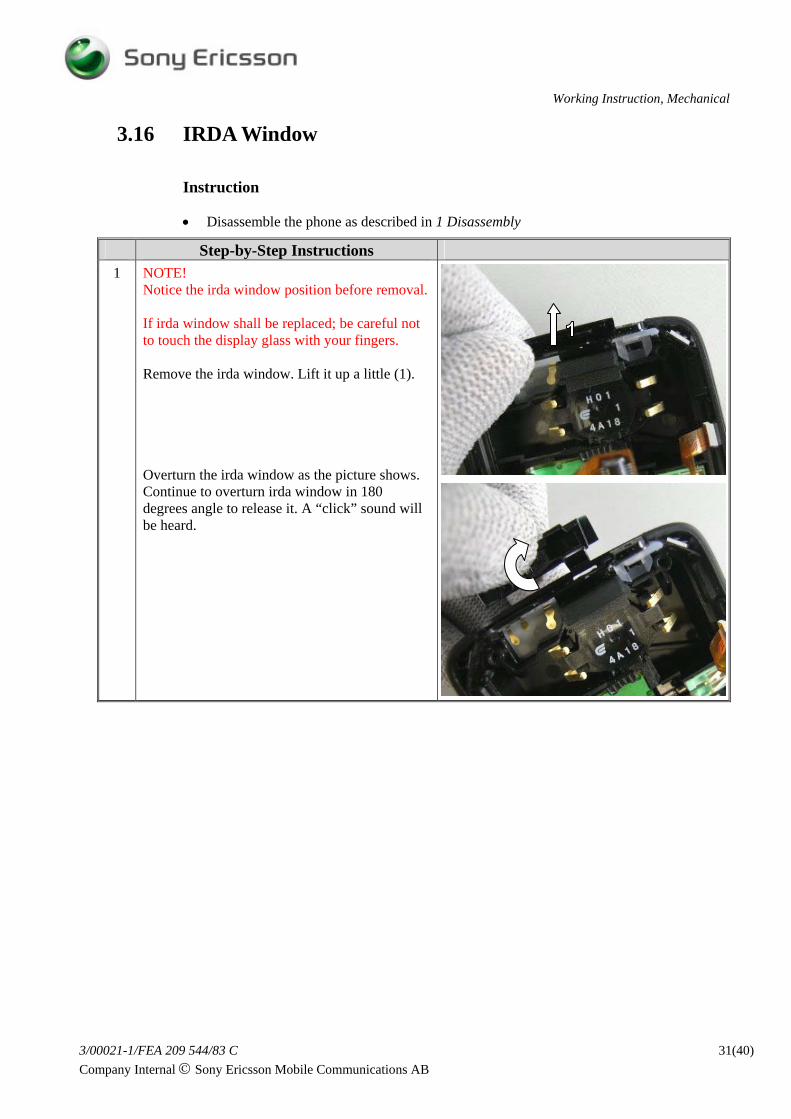
Step-by-Step Instructions 1 NOTE!
Notice the irda window position before removal. If irda window shall be replaced; be careful not to touch the display glass with your fingers. Remove the irda window. Lift it up a little (1). Overturn the irda window as the picture shows. Continue to overturn irda window in 180 degrees angle to release it. A “click” sound will be heard.
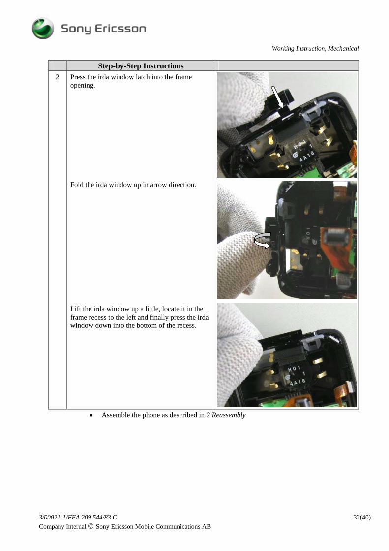
Step-by-Step Instructions 2 Press the irda window latch into the frame
opening. Fold the irda window up in arrow direction. Lift the irda window up a little, locate it in the frame recess to the left and finally press the irda window down into the bottom of the recess.
• Disassemble the phone as described in 1 Disassembly
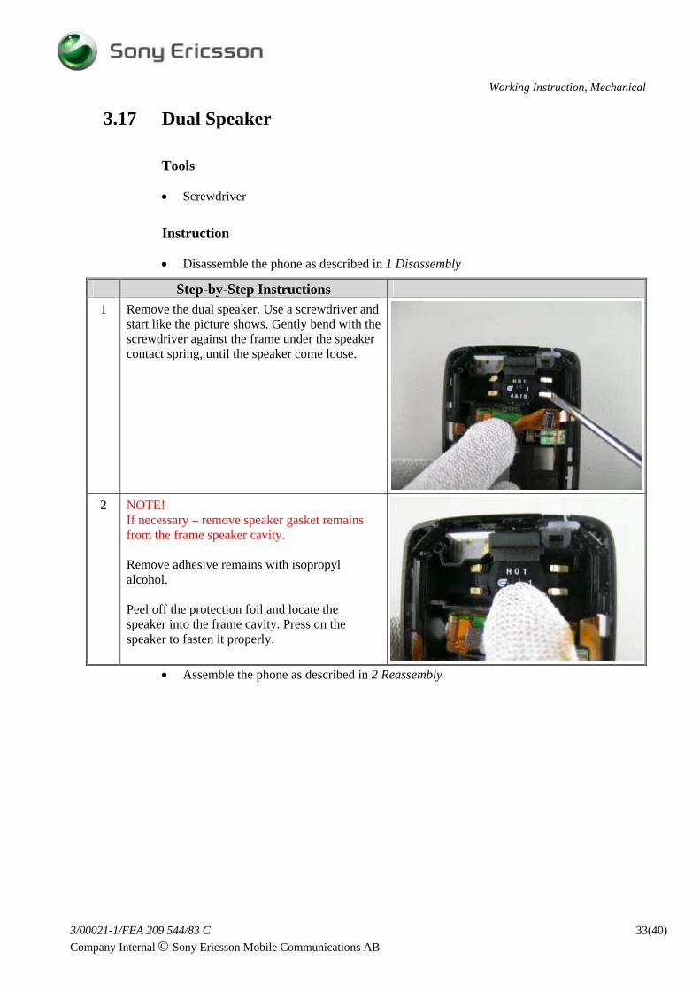
Step-by-Step Instructions 1 Remove the dual speaker. Use a screwdriver and
start like the picture shows. Gently bend with the screwdriver against the frame under the speaker contact spring, until the speaker come loose.
2 NOTE! If necessary – remove speaker gasket remains from the frame speaker cavity. Remove adhesive remains with isopropyl alcohol. Peel off the protection foil and locate the speaker into the frame cavity. Press on the speaker to fasten it properly.
• Disassemble the phone as described in 1 Disassembly
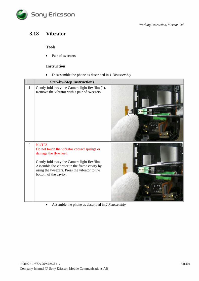
Step-by-Step Instructions 1 Gently fold away the Camera light flexfilm (1).
Remove the vibrator with a pair of tweezers.
2 NOTE! Do not touch the vibrator contact springs or damage the flywheel. Gently fold away the Camera light flexfilm. Assemble the vibrator in the frame cavity by using the tweezers. Press the vibrator to the bottom of the cavity.
• Disassemble the phone as described in 1 Disassembly
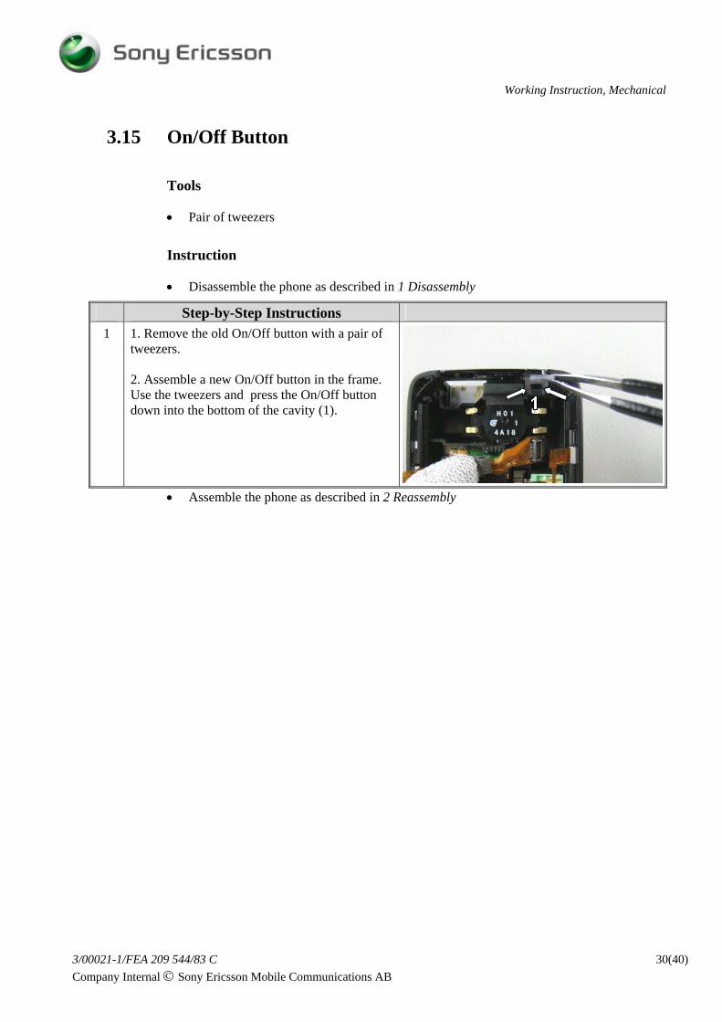
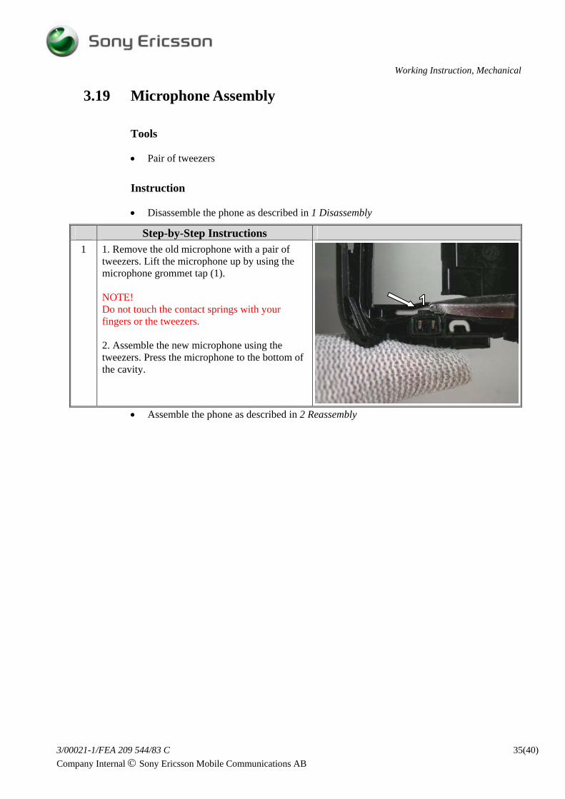
Step-by-Step Instructions 1 1. Remove the old microphone with a pair of
tweezers. Lift the microphone up by using the microphone grommet tap (1). NOTE! Do not touch the contact springs with your fingers or the tweezers. 2. Assemble the new microphone using the tweezers. Press the microphone to the bottom of the cavity.
3.20 Camera Part (VGA) and Camera Conductive Gasket
Tools
• Pair of tweezers
Instruction
• Disassemble the phone, including the antenna cover, as described in 1 Disassembly
Step-by-Step Instructions 1 NOTE!
Be careful not to touch vibrator and microphone contact springs or vibrator flywheel. Remove the camera assembly by holding the flexfilm with your left thumb and forefinger. Gently lift the camera up.
Step-by-Step Instructions 2 Take the camera assembly and assemble the
camera conductive gasket as the picture shows (1). The Camera Part (VGA) is delivered as spare Part without the conductive gasket mounted. For full functionlity of the phone it is very important that the gasket is mounted according to instruction. Place the camera assembly into the cavity and lift the frame up. Press the camera assembly to the bottom of the cavity with your fingers. Turn the frame assembly around and check that the camera grommet edge is visible all around the frame opening (arrows).