Kate Cory_instructions.qxd 1/10/07 12:20 PM Page 1
2
HISTORYHISTORY
The first Model Shipways kit of the Kate Cory was developed in 1972 by the original company in Bogota, New Jersey. The plansand instructions were prepared by noted marine artist and historian Erik A.R. Ronnberg, Jr. The design is based on plans andother documentation published by the Old Dartmouth Historic Society in 1970. These particular documents were also preparedby Erik Ronnberg and developed from historical records. These excellent documents are available as a plan set and booklet fromthe New Bedford Whaling Museum (See Bibliography).
In 1995, Model Shipways had been sold and became a division of Model Expo, Inc. in Mt. Pocono, PA. The kit was reissued at thattime with some additional parts such as laser-cut whaleboat lifts. However, the plans and instructions were the same as those usedfor the original kit.
Our new 2007 kit is another reissue by Model Shipways (now located in Hollywood, Florida). The original plans have beenretained, but the kit has been updated with a completely new instruction manual which follows the most recent format developedfor Model Shipways kits. In addition, a more complete set of supplies for building the model is provided, especially more riggingline sizes and wood strips and sheets. The fittings are cast from lead-free Britannia metal and there are more laser-cut wood parts forease of construction. Templates are provided to aid in hull carving and unlike older Model Shipways solid hull kits which featuredsolid block deck structures, this kit features structures built up from stripwood and sheets. Easier to detail, more fun, and more likethe real thing.
In addition to the brig rig, the plans show the early schooner rig. However, the instructions and parts provided in the kit are for thebrig rig only.
Throughout the middle of the 19th century, activities in the Atlantic whale fishery were carried out in small fore-and-aft schoonersand brigs. The latter are hermaphrodite brigs, or “half-brigs”, or simply “brigs” to use the jargon of laconic whalemen.
Kate Cory was built in 1856 by Frank Sisson and Eli Allen in Westport Point, Massachusetts for Alexander H. Cory, one of the lead-ing merchants of that community. The ship was named after Alexander’s daughter. Registered at 132 tons net, Kate Cory was 75' 6"in length between perpendiculars, 9' 1-1/2" depth, and had a beam of 22' 1". The last large vessel to be built within the difficultconfines of that port, she was also one of the last small whalers to be built specifically for her trade; most of the later whaling brigsand schooners were converted freighters or fishermen.
While originally rigged as a schooner, Kate Cory was converted to a brig in 1858, this rig affording steadier motion in heavy seas orwhile cutting-in whales, not to mention saving much wear and costly repair to spars, sails and rigging.
Five voyages of moderate success culminated in Kate Cory’s destruction off the Brazilian coast in 1863, when she was captured byC.S.S. Alabama and burned. Subsequent suits for war losses caused her owners to assemble all business papers and receipts for thevessel as evidence for their claims. The careful storage of these documents and their subsequent recovery have afforded a nearlyunique opportunity to examine a small whaler in great detail.
Kate Cory_instructions.qxd 1/10/07 12:20 PM Page 2
3
Brief History ..........................................................................2Before You Begin....................................................................4Working With Plans & Parts..................................................4 What You’ll Need to Start.......................................................4 Painting & Staining ............................................................4-5
Stage A: Shaping the Pre-Carved Hull1. Using the Templates ...........................................................6 2. Carving the Hull ................................................................6 3. Carving the Bulwarks .........................................................64. Carving the Inside of the Stern...........................................65. Carving the Deck ...............................................................6
Stage B: Completing the Basic Hull Structures1. Outboard Planksheer Strip and Wales ................................72. Transom Moulding.............................................................73. Keel, Stem Post, Stem Knee & Sternpost ........................7-8 4. Rudder ...............................................................................8 5. Mast Holes & Bowsprit Hole .............................................8 6. Holes to be Drilled as Work Progresses...............................87. Coppering the Bottom..................................................8-10 8. Main Deck Planksheer, Planking, & Sheathing.............9-10 9. Quarter Deck Planking .................................................9-1010. Gangway Framing and Sheathing................................9-1011. Bulwark Stanchions, Cap Rails, Pin Rails & Channels.10-1112. Buffalo Rail, Knightheads, & Topgallant Rail ...........10-11
Stage C: Mounting the HullMounting Board with Two Pedestals ....................................12
Stage D: Adding the Hull Details1. General Notes ..................................................................122. Completing the Bulwark Details ......................................123. Port Lights and Hawse Pipes ............................................124. Samson Post, Riding Bitts, Windlass, & Anchor
Kits by Model Shipways..................................................34-36
Construction Stages & Table of ContentsConstruction Stages & Table of Contents
Kate Cory_instructions.qxd 1/10/07 12:20 PM Page 3
4
Before You Begin
The Kate Cory is an interesting model forbeginner and expert alike. This kit contains asolid hull which has been machine-carvedfrom select, medium-hard, fine-grained bass-wood. This style hull provides a quick andeasy lesson in the basic shapes and propor-tions of hull design and helps to developwoodworking skills. Although the exterior ofthe hull has been carved close to the hulllines as shown on the plans, further carvingis necessary for reasons of accuracy. Carvingand finishing the hull to its final shape arediscussed in the instructions.Constructing the Kate Cory model also willprovide you with the opportunity to developsome scratch-building techniques. Duringconstruction, you may want to substitutesome of the kit fittings with your own cre-ations. By all means try them, especially ifyou think you can improve the model.If you are a beginner, completing this modelwill prepare you for a more complicatedmodel such as the Pride of Baltimore II andConstitution, which are outfitted with aplank-on-bulkhead hull. In the meantime,happy modeling!
Working with the Plans & Parts
Before starting model construction, examinethe kit and study the plans carefully. Familiar-izing yourself with the kit will serve twopurposes. First, it will let you determine thatall parts have been supplied as listed. And sec-ond, you’ll be surprised at how quicklyhandling the parts allows you to better under-stand the kit requirements. Try to visualizehow every part will look on the completedmodel. Also, determine ahead of time whatmust be done first. The instructions will helpyou in this regard, but a thorough knowledgeof the plans at the outset is essential.
It is also suggested that all small fittings andhardware be sorted into labeled boxes or com-partments to avoid loss during the buildingprocess.
Three Plan Sheets and One Template Sheetare provided:
1. Hull Plan - Sheet 1 of 3
2. Rigging Plan - Sheet 2 of 3
3. Rigging Details - Sheet 3 of 3
4. Hull Templates (heavy stock paper)
In addition, a set of sketches appears through-out the instruction manual to furtherillustrate the various stages of construction.
The Kate Cory kit is manufactured to a scaleof 3/16" = 1'0" and matches the plans. Con-sequently, most of the dimensions can belifted directly from the plans using a “tickstrip”. This is simply a piece of paper (a roll of
calculator paper tape works very well). Mark adimension from the plan onto the tick stripand transfer it to the model.
The Kate Cory kit is supplied with Britanniametal, brass, as well as wooden fittings toeliminate problems in making such partsfrom scratch. Because the Britannia metalcontains no lead, there are no possible corrosion problems. Many of these fittingswill require final finishing before installing onthe model.
Before painting the cast-meal fittings, cleanthem up by removing all the mold-jointflash. To do this, use a No. 11 hobby bladeto cut the flash, then sand with fine sand-paper. It is also suggested that you cleanthe fittings thoroughly with warm soapywater before applying primer. Make surethey are rinsed thoroughly and allowed todry before painting.
What You’ll Need To Start
The following tools and supplies are recommended for the construction process.Modelers who have built before may havetheir own favorites. Almost all are availableat Model Shipways web site, www.modelexpo-online.com.
A. Tool SetA small carving tool set, or individual
chisels and gouges for shaping the hull andwhaleboats.
B. Sharpening StoneNecessary to keep the tools razor sharp
C. Knives and Saws1. Hobby knife with No.11 blades2. Razor or jeweler’s saw
D. FilesSet of needle files
E. Clamps1. A few small C-clamps2. Several wooden clothespins3. Rubber bands
F. Boring Tools1. Set of miniature drills: #60 to #802. Larger bits for holes such as mast,
hawse pipe, and mooring pipe holes3. Pin vise
G. Miscellaneous1. Tack hammer2. Tweezers3. Small fine pointed scissors4. Miniature pliers
H. SandpaperGarnet or aluminum oxide sandpaper (#100 to #400 grit)
I. Finishing1. Paint brushes
a. Fine point for detailsb. 1/4" to 1/2" flat square for hull
J. Supplies(will be covered in detail in the Painting & Staining section and throughout instructions)1. Paints2. Primer3. Stain and Varnish4. White or Carpenter’s (yellow)
Note about glues: White or Carpenter’s yel-low wood glue will suffice for most of themodel. Five-minute epoxy provides extrastrength for gluing fittings. Cyanoacrylate(Super) glue, called CA glue for short, suchas Zap is excellent for quick adhesion and isideal for dabbing onto a rigging seizing tohold it in place. The best CA glue for mostapplications is a medium viscosity gap-fillingtype. The watery-thin type is recommendedonly to fill a narrow crack by capillaryaction. For CA glue, you can also purchase aliquid accelerator such as Zip Kicker. A sprayor drop of the accelerator will instantly curethe glue. This is handy to eliminate clamp-ing parts for long periods of time waiting forglue to harden.
Use CA glue with caution. You can easilyglue your fingers or eyelids together and thefumes can burn your eyes. It would be agood idea to have a bottle of CA Debonderon hand. This product will dissolve the glueif you do get it on your body.
Painting and StainingIt may seem strange to begin an instructionmanual with direction on applying the finish-es to the model. Not so! Much time and effortcan be saved and a more professional resultcan be obtained if the finishing process is car-ried out during construction. Proper timingin application of finishes and the use of mask-ing tape to define painted edges shouldeliminate unsightly glue marks and splotchystained surfaces. In the end, following thesegeneral suggestions will be to your advantage.
Paint Colors:The color scheme for Kate Cory is as follows:
Hull below waterline (copper line)- Copper sheathing or copper paint
Hull planking from copper line to underside of cap rail - Black
Kate Cory_instructions.qxd 1/10/07 12:20 PM Page 4
5
Planksheer outboard, bulwark cap rail,buffalo rail, topgallant rail, catheads,cheek knees, whaleboat davits and cranesand tail feathers, channels, belaying pinrails, and outboard guard stanchions onboth sides of gangway (cap rail to copperline) - White
Ironwork - Chain plates Red-Lead; smalleritems Black. Large items such as windlassgear and anchors Black or Red-Lead.
Bulwarks Inboard (underside of cap railto and including the planksheer inboard)- Light Green
Deck planks and deck sheathing - Natural Varnish*
Companionways, galley, binnacle chest,and skylight - Light Green sides and top.
Hatches - Light Green coamings with Gray covers.
Try Works - Black try-pots; Copper clad orCopper paint top around pots, and chim-neys; Gray siding around the try works;Brick color front with Black fire doors.
Cooling tank - Copper or Copper paint boxwith a Natural Varnish* top cover.
Cooper’s bench with chicken coop under -Light Green with weathered dark brownbench top; Black bench vise.
Tiller and steering wheel - MahoganyBrown.
Windlass barrel - Dark Brown with Blackwhelps and ratchets.
Riding bitts, main bitts, and samson post- Light Green
Quarterbitts , fluke and belly chain bitts,and log pump barrels - Natural Varnish*.However, since these are castings in the kit,paint to look like stained wood. In addi-tion, the bitts have a copper sheet or copperpaint cap.
Scroll work on trailboards between cheekknees, and billethead - Gold
Transom Eagle - Gold; Red eyes; Yellowbeak; Green olive branch; Brown arrows.
Transom Name - White lettering andmoulding strips above and below name.
Fore Masts - Light Green from deck(including mast coat) up to the belaying pinspider band, then White to the top of fore-mast cap including the cross trees andtopmast doubling below the cap; then Nat-ural Varnish* up to the topgallant mastfuttock band; White to the topmast capincluding the cross trees and topgallant dou-bling below the cap; Natural Varnish* to aWhite pole at the top. Also, the royal cross
trees are White.
Main Masts - Light Green from deck(including the mast coat) up to and includ-ing the boom saddle. Above the boomsaddle, Natural Varnish* up to the topmastfuttock shroud band, then White from thefuttock band to top of the mainmast capincluding the cross trees and topmast dou-bling below the cap. The topmast portionabove is Natural Varnish* except the crosstrees for the lookout shrouds and the pole attop are White.
Yards, gaff, and boom - White
Bowsprit - Light Green inboard; Black out-board to the billethead, then White.
Martingale (Dolphin Striker) - White
Jibboom - Black out to the billethead (sameline as on bowsprit), then White to thebowsprit cap; then Natural Varnish* withWhite pole.
Blocks - White (varnished when new butpainted later)
Deadeyes and Bullseyes - Black (tarred)
Pennant - Dark Blue field with White “C”and Bright Scarlet tail.
Whaleboats - The color scheme for theseboats can be quite bright and to the fancy ofthe model builder:
Inboard ceiling - Gray and other parts Light Green
Gunwale & gunwale (top) strake - Black
Sheer strake (second strake down) -White, Blue, or Dark Green
Bottom - White, Dark Green, Blue, or Black
Many boats also had a bright slash of colorpainted across the bow (as if the bow hadbeen dipped in paint); this could be anybright color. Simple geometric designs mayhave been painted as well. These bright col-ors served as identification marks for boatsbelonging to specific vessels, to avoid confu-sion in crowded whaling grounds.
* Natural Varnish items should be a light tanstain such as pine or oak with a final coat ofclear flat or satin finish (see notes on stains& finishes below).
Note - Within the boundaries of paintedareas, the ironwork was usually painted thesame color. This is especially true for mastsand spars.
Paint:Use a flat-finish paint. Model Shipways lineof acrylic paints are available in the recom-mended colors. You may also purchase an
already assembled Kate Cory paint kit fromModel Shipways web site, www.modelexpo-online.com.
Primer:Use a grey primer (one is provided with theKate Cory paint kit). The grey color willhighlight sanding scratches and other defectsbetter than white primer. Prime all wood-work to be painted, and prime all metalfittings. Lightly sand the primed items. Use aspackling compound such as Pic-n-Patchbrand to fill any scratches and defects, thenre-prime.
Stains & Finishes:For natural finished wood, use a protectivecoating after staining, such as low-sheenpolyurethane varnish. You can also use anoil-resin mix like the ones sold by ModelShipways or Minwax.
For the deck and natural masts and spars,Model Shipways stain or Minwax can beused. These are a combination stain-finishthat will provide a light tone to the wood.The deck plank edges can be painted priorto installation with any dark color to simu-late caulking.
The staining of all wood parts should bedone before gluing, especially if any CA glueis used. The stain will not penetrate driedglue and leave ugly white areas in the finish.
Brushes & Procedures:Use good quality soft sable or synthetic hairartist’s brushes. A small pointed brush isgood for details. For the main hull areas, usea 1/4" to 1/2" flat brush.
Before painting, clean the model with a tackrag. Apply your paint in smooth and evenstrokes, overlapping them as you go. Thinthe paint enough to eliminate brush strokes,but not run. You will need three or fourcoats of the light colors to cover the greyprimer and maybe only two coats of thedark. Check your finish between coats, sandand add spackle as necessary to get rid of anyblemishes.
Anywhere two colors meet, use maskingtape. Electrician’s black plastic tape or any ofthe hobby tapes made of plastic film areideal. They leave a nice edge and are notoverly sticky. Do not use drafting tape unlessit is Chart-pak brand. The edges are some-what wrinkled and paint may run underthem. A good trick; seal the edge of maskingtape with a clear flat finish and let dry thor-oughly. This will really prevent paint fromrunning under the tape.
Kate Cory_instructions.qxd 1/10/07 12:20 PM Page 5
6
STAGE A: SHAPING THE PRE-CARVED HULLSanding alone will not shape the hullenough to precisely match the hull lines.Some carving is required, especially at therail, keel, bow, & stern areas.
1. Using the TemplatesFor exact carving to hull lines, a template isrequired for the hull profile and each of thestations. You will find a template set printedon heavy stock paper in the kit. Cut the tem-plates out carefully with a No. 11 hobbyknife. Do not use scissors! You will want anice smooth edge.
2. Carving the HullCut a wooden block from scrap to about 4"x 1" x 3/4" thick. Screw the block to thedeck (forward of the quarter deck step) sothe model can be held in a bench vise forcarving. First, check the accuracy of the pro-file using the profile template and correct itas necessary.
Next, mark the centerline, rabbet lines(where hull meets keel) and station lines onthe model (Figure A-1). Note that the widthat the keel, stem, and sternpost (rabbet torabbet) is 3/16". Keep these areas flat as the3/16" keel, stem post, and sternpost will beglued on later. Place the station marks on thecenter of the hull bottom and on top of therails so the marks won’t be carved off as youwork. Also, add marks for the width of thehull at each station on top of the rail. Mea-sure the marks from the centerline of themodel so the marks will be the same portand starboard.
As shown on the sketch, a good way to startis to cut a slope at the rail back to the hullwidth marks to establish the width of thehull at the rail for the entire hull length. Younow have a line to carve to as you fit thetemplates. Next, start carving approximatelyat mid length (maximum beam) andprogress forward, then aft, using chisels andgouges to cut away excess wood. Avoid carv-ing against the grain by shifting forward oraft until you find a spot where you are goingwith the grain. Basswood carves easily, soyou probably won’t have much problem withthe grain.
Carve very slowly and take off a little woodat a time. Fit the templates as you go. Carveuntil the template fits reasonably well, thenuse sandpaper to obtain the final shape. Atfirst, the templates will not fit very well,especially at the stern where a fair amount ofwood needs to be carved off. You must com-pare the template to the hull and visuallydecide where to remove wood. Cut a littleoff, then re-check the template.
Finally, draw a few horizontal pencil lines(like waterlines) and the vertical stationlines on the hull. Use these to visually checkthe shape of the hull. Hold the hull at vari-
ous angles, and look to see if the pencillines are fair (even). If you have any unfair-ness, dips or bumps, they can usually befound with this visual check. You can alsouse a stiff stick of wood, about 3/32"square, and lay it on the hull at variouslocations. Dips and bumps in the hull willshow up under the stick.
Wales - The wales of the real ship are astrake of thicker planks located along thehull sides below the outboard edge of theplanksheer. The hull templates used forshaping the hull do not include the protrud-ing wale planks. For our solid hull model, itis much easier to shape the hull smoothaccording to the templates, then apply theadditional thickness of the wales using bass-wood strips. The installation of the waleswill be discussed in Stage B.
3. Carving the BulwarksMake yourself a temporary cradle to securethe hull while carving. This cradle also willserve to hold the model for most of theremaining work. Make the cradle so themodel sits in it with its waterline parallelto the baseboard and table. The tops of thecradle should be below the waterline.Later, when you are ready to paint, attacha pencil on top of a wooden block andslide it along the table to mark the loca-tion of the waterline.
The machine-carved hull has bulwarksthicker than scale so they won’t breakwhile inside the kit box and because ofcarving machine limitations. The uppersurface is cut to the underside of the caprail. After finishing the outside of the hull,the bulwarks will probably still be toothick. The bulwark should be about 1/32"thick from about the forward side of theforward mooring port back to the stern. Ifnot, you will also need to carve the insideof the bulwarks. Forward of the forwardmooring port the real ship bulwarks con-
sist of the bulwark planking, stanchions,hawse timbers, and knightheads, and cov-ered inboard with ceiling planks. For thesolid hull model the bulwarks in this areacan therefore be thicker to account for theceiling planked area.
Carving the bulwarks is the most difficultpart so work slowly as you carve (Figure A-2). After carving, sand the surfacessmooth. If you happen to have or want tobuy a powered rotary tool like a Dremel,there are many cutters available to quicklyreduce the bulwark thickness.
Option: If you find carving the bulwarkstoo tedious, cut off the bulwark flush withthe deck and build the bulwark with bass-wood sheet (not included in kit), then addthe stanchions.
Gangway - The bulwark on the starboardside will need to be cut out In way of thegangway. For now, leave it as is forstrength. Cutting the bulwark and framingthe gangway will be discussed in Stage B.
4. Carving the Inside of the SternCarving the stern area is essentially the sameas the side bulwarks, only you have to dealwith the curve and the slope. Just be extracareful while carving. The stern is also thick-er like the bow bulwarks as on the real ship itis composed of transom plank, stern frames,and covered by ceiling planks inboard.
5. Carving the DeckThe deck will be planked. All that is need-ed now is to clean out the corners with achisel and smooth out the machine-carveddeck with a scraper or sandpaper, makingsure you have a nice smooth camber and allthe intersections with the bulwarks, stern,and quarter deck step, are clean, ready forthe planking.
FIG. A-2 CARVING BULWARKS
USE GOUGEFIRST
SMOOTHWITH CHISEL
Kate Cory_instructions.qxd 1/10/07 12:20 PM Page 6
7
The following paragraphs are numbered inorder of a suggested step-by-step procedure,but you are the final judge. Proceed in a waythat suits your building methods best, keep-ing in mind how you will hold the hull whileadding the various components, avoidinginterferences, and preventing any damage toalready assembled units.
Note - Basswood strips are used for anumber of components. Narrow stripsbend edgewise fairly well. However, whenyou run into a situation where the stripwill not bend to conform to the propercurve, you will need to either steam-bendthe strip or cut the part out of wider woodsheet. Several sheets are provided in the kitfor this purpose.
1. Outboard Planksheer Strip and Wales
Outboard Planksheer Strip - On the maindeck of the real ship, the planksheer is a con-tinuous unit at the deck edge inboard tooutboard with holes where the bulwark stan-chions (timberheads from frames below)penetrate. For our solid hull model with acarved bulwark, the main deck planksheerwill be added in two separate strips; one
inboard and one outboard. Make sure thetwo separate strips are in line. Aft of thequarter deck step the planksheer is only out-board on the model as well as the real ship.Fit the outboard planksheer strips (3/32"ver-tical x 1/16") on both sides of the hull. Onthe real ship the outer edge of the planksheerhas a “hawksbill” shape (large and small half-rounds) but for this small scale model just ahalf-round edge is sufficient. Wales - For the model, the thicker waleplanks will be indicated by adding four1/32" x 3/32" basswood strips on the solidhull, bow to stern. The top strip butts upunder the outboard planksheer strip. Afterapplying the strips, feather the lower edge ofthe bottom plank into the hull.Figure B-1 is a section thru the wales andoutboard planksheer strip.
2. Transom MouldingAbove and below the stern name there aretwo moulding strips. Use 1/32" squarebasswood and round the edges after theyare in place.
3. Keel, Stem Post, Stem Knee & Sternpost
The keel, stem post, stem knee, & sternpostare laser-cut parts. Taper the stem post andstem knee and install the parts. Use pins ordowels to position the parts before gluing.Scrape off any glue squeeze-out. Fill any gapsremaining at the glue joints with wood fillerand then sand (Figure B-2).
Note: The plan shows a shoe on the bottomof the keel. The shoe is a replaceable keelbottom plank on a real ship as the bottom ofthe keel tends to deteriorate from dry dock-
FIG. A-1 MARKING THE HULL
RABBET
RAIL
WOOD TO BECUT AWAY
MARK CENTERLINE
MARK ALLSTATION LINES
MARK STATIONS &HULL WIDTHS
ON TOP OF RAIL
START CARVING LIKETHIS TO ESTABLISH HULLWIDTH AT RAIL
FITTEMPLATES
MARK RABBET LINES
WIDTHAT RAIL
MARK HULLWIDTHS AT
EACH STATION
MEASURE FROMLINES PLAN
3/16"
3/16"
3/16"
STAGE B: COMPLETING THE BASIC HULL STRUCTURES
BULWARK
OUTBOARDPLANKSHEER
WALES
FEATHERLOWERPLANK
FIG. B-1 OUTBOARD
PLANKSHEER & WALES
Kate Cory_instructions.qxd 1/10/07 12:20 PM Page 7
8
ing and lack of painting. For the model, theshoe has been incorporated into the laser-cutkeel, so is not a separate piece.Billethead - The billethead is part of thelaser-cut stem knee but needs to be carved. Asimple design is appropriate (Figure B-3).Cheek knees and trailboards - The cheekknees with a trailboard in between are bestinstalled now to strengthen the stem knee.The 1/16" thick cheek knees are curved intwo planes. You can cut the plan view shapefrom a thicker piece, then carve the curvelooking from the side. Another option is tosteam bend the profile, but a more positivealternative for holding the curve is to lami-nate two 1/32" thick pieces together. Youwill need a simple form to hold the shapewhile the glue dries. A 1/32" thick trailboardwith Gold painted scroll work over blackbackground can be fitted between the kneesor just paint the scroll work on the stemknee (Figure B-4). 4. RudderThe rudder is a laser-cut part. Drill the holein the hull for the stock. The rudder istapered and has a round front edge. Thestock portion is round. The pintles & gud-geons can be made from brass strip,self-adhesive copper tape. See Figure B-5 forconstruction.Option - The stock (also called the rudderpost) need not go completely thru a hole.You could have a shallow hole on the bottomof the hull with a short stock in the hole. Upon the deck, drill another short hole and fitthe upper end of the stock separately. 5. Mast Holes, & Bowsprit HoleThe mast holes should be about 1" deep.Later, cut the mast dowels to fit this depth.Make a guide jig for your drill so you get thecorrect rake angle aft and have the hole per-pendicular to deck looking fore and aft. Itwould be a good idea to drill the hole a littleoversize and use shims around the masts forfine tuning.Cut the hole at the bow under the cap railfor the bowsprit (1/4" wide x 5/16" high).The top and bottom of the hole needs to fol-low the angle of the bowsprit. Use a scrapwood piece same dimensions as the bowsprit(assuming you have not yet made thebowsprit) as a guide to shape the hole.6. Holes to be Drilled as
Work ProgressesThere will be many small holes to drill as thework progresses. For example, holes forscuppers, port lights, Britannia fittings, eye-bolts, and belaying pins.7. Coppering the BottomYou have the option of painting the hull bot-tom or sheathing it with thin copper.Sheathing is not that difficult but it is tediousand time consuming. Self-adhesive coppertape is included in the kit. This is a lot easierto apply than using contact cement or some
other type of glue with bare copper. Eachplate should be 3/4" long. When removingthe backing from the tape, be careful and nottouch the adhesive side any more than youneed to. Grease and dirt will reduce the adhe-sive power. After the coppering job iscompleted you can touch any loose ends withthin CA glue, and apply a flat clear coating.Each side of the hull is coppered in two dis-tinct “belts”: upper and lower. Within eachbelt the plates are more or less parallel. Thegore line is the intersection of the upper andlower belt. Re-attach the temporary deck block if you
have removed it, and place the model upsidedown in your vise. Start the coppering at thekeel and at the stern. Work forward anddownward (with model upside down), lap-ping the plates about 1/32" as you go. Thelower belt is installed down to the gore line.At the gore line extend the plates just belowthe line. Now, start the upper belt at the goreline. The plates lap over the lower belt plates.Continue to the waterline. Figure B-6 illus-trates the general layout and process. FigureB-7 is a pictorial view of how the sheathinglooks at the bow, stern, and on the rudder.
Note - The bottom of the keel, stem, stern-
STERNPOST
PIN (OR DOWEL)TYPICAL
KEEL
INDENTCUTS
STEM KNEE
TAPER
STEM POST
TAPER
FIG. B-2 KEEL, STEM POST, STEM KNEE & STERN POST
FIG. B-3 BILLETHEAD
FIG. B-5 RUDDER
FIG. B-4 CHEEK KNEES
CUTGROOVE
CARVESHAPES
TRAILBOARD
OPTION - LAMINATETWO WOOD SHAPES
LASER-CUT STEM KNEE
ROUND
LASER-CUTRUDDER
RUDDER(TOP VIEW)
PINTLE GUDGEON
SOLDER OREXPOXY PIN
PIN IS OPTIONAL
PINTLE & GUDGEON DETAIL
BRASS STRIP(OPTION: COPPER TAPE)
STERNPOST(TOP VIEW)
GUDGEON
PINTLE
TAPER &ROUND THE FRONT
Kate Cory_instructions.qxd 1/10/07 12:20 PM Page 8
9
post, and rudder have a cap plate (DressingBelt) at the edge. The cap plates will go overthe other plates.When you finish the lower belt, and beforestarting the upper belt, it would be a good ideato cut the plates parallel to the gore line andabout 1/16" from the line under the upperbelt. As you can see in the sketch this wouldeliminate the triangular ends which wouldshow under the thin tape upper belt plates.8. Main Deck Planksheer,
Planking, & SheathingThe main deck (forward of the quarter deckstep) is planked but is mostly covered withpine sheathing to protect the deck fromexcessive wear while cutting-in whales andmincing blubber. Only a narrow strip ofdeck planking between the sheathing andthe planksheer, and an area forward of theforward companionway is visible. The deckplanking is smaller in width than the sheath-ing planks. For the model, there is no needto actually plank the deck under the sheath-ing. The visible deck planked areas will beplanked with 1/32" thick basswood stripsand the sheathing planked areas with 1/16"thick strips. Inboard Planksheer - Start the decking byadding the inboard planksheer strip (3/32"thick x 3/16" wide) along the bulwarks. Upforward the planksheer strip is smaller inwidth as the bulwark is planked with ceilingplanks. Also, the planksheer becomes a littledeeper forward. You will need to taper athicker planksheer. The inboard edge of theplanksheer is chamfered. See Figure B-8.Deck Planking - Next, add a 1/32" thick x1/16" wide strip along the planksheer fromthe quarter deck step to the bow. This will bethe visible portion of deck plank along theplanksheer. Just forward of the forward com-panionway add the 1/32" thick x 3/32" widevisible deck planks (Figure B-9).Deck Protective Sheathing - The sheathingcan now be added using 1/16" thick x 1/8"wide planks. Notice there is an athwartshipfairing piece at the forward end of thesheathing planks, covering the end grain.After the planks are installed, round the edgeof the forward fairing piece and the sideplanks (Figure B-10).Padding - Around the masts and under theriding bits there is a pad, actually just thickerplanks on the real ship. To indicate the pads,add 1/32" thick planks on top of theinstalled planks. Note - Notice that on the main deck boththe deck planks and the sheathing planks areparallel to the centerline.Reminder - Don’t forget to darker the edgeof each plank to represent the caulkingbetween planks. Refer to the painting section.9. Quarter Deck PlankingInstead of a planksheer there is a similarmargin plank on the quarter deck inboard
only. This is called a waterway or coveringboard (3/32" thick x 3/16" wide with achamfered inboard edge). It runs along thebulwarks and also across the stern. Sincethere is no protective sheathing on the quar-ter deck, the deck will be planked with1/32" thick x 3/32" wide planks. Across thestep in the deck add the end plank whichcovers the decking end grain (Figure B-11).Note - Unlike the main deck, the quarterdeck planks are laid parallel to the waterwayand not the centerline.Reminder - Don’t forget to darker the edgeof each plank to represent the caulkingbetween planks. Refer to the painting section.10. Gangway Framing
and SheathingOn the starboard side of the hull cut out thesection of the bulwark from the forward sideof the forward guard stanchion back to theafter side of the aft guard stanchion anddown to the top of the planksheer strips. Cutcleanly and you can use the cut out portionfor the false bulwark. If you mess it up it caneasily be replaced by 1/32" thick basswood. Within the same area as above cut back theoutboard edge of the planksheer to be flushwith the wale plank below (Figure B-12).The next step is to shape the two end guardstanchions from 1/8" thick basswood andglue them in place. The bulwark and captenons will fit into the grooves cut in the
guards so keep this in mind when you makethe false bulwark. Figure B-13 illustrates theassembly thus far. Once the guards are in place add the pad ontop of the planksheer. The pad (1/16" thick)fits between the guards. The extent inboardis to the edge of the inboard planksheerchamfer. Outboard it goes to 1/32" beyondthe planksheer and wales. The pad has thesquare holes to fit the bottom of the falsebulwark stanchions. The outer edge of thepad is covered with a metal angle on the realship but can just be painted on the model.At the forward corner of the guard stanchionand pad there is a small chock (Britanniacasting). You can then add the sheathingbelow the pad. Use 1/32" x 3/32" verticalstrips, then feather the bottom into the hull(Figure B-14).Note - The hull padding just aft of the gang-way is there to cover the lower ends of twomain shroud chain plates. Hold off addingthe padding until the chain plates have beeninstalled. The padding is a little thicker thanthe sheathing in way of the gangway.False bulwark - Using the section removedfrom bulwark or a new piece of 1/32" bass-wood, add the cap rail with tenons on eachend, and the stanchions (Figure B-15).Display - You can display your model withthe false bulwark in place or removed. Ifremoved, it probably was lashed to the lash-ing rail somewhere near on the bulwarks.
FIG. B-6 COPPER SHEATHING PROCESS
GORELINE
UPPERBELT
GORELINE
LOWERBELT
Begin coppering at keel bottom; start aft and work forward. Work upward to the Gore Line, overlapping it slightly.
Begin the upper belt at the gore line; start aft, work forward, work upward to the water line,feathering the top plates to suit the waterline profile. Waterline “Dressing Belts” were seldomfound on Whalers.
Follow closely the Copper Sheathing in the plans, Sheet 2.
Water Line
3. . . . and upward.
2. Work forward. . .
1. Begin coppering at KEEL BOTTOM.
Kate Cory_instructions.qxd 1/10/07 12:20 PM Page 9
10
Cutting Stage - Elaborate cutting stagescommonly associated with whalers are diffi-cult to trace to the pre-Civil War period.Most likely such stages did not appear untilthe 1870s. A simple stage would be appro-priate for Kate Cory. Though not shown onthe plans a suggested stage is shown in Fig-ure B-16. Use it or not. 11. Bulwark Stanchions, Cap Rails,
Pin Rails, & ChannelsStanchions - Install the bulwark stanchionson the inside of the carved bulwarks on topof the planksheer (main deck) and waterway(quarter deck). The stanchions (3/32" squarebasswood) should have a slight upward taperas they are timberheads tapering from largerframes below. However, using the squarestrip without tapering is an option. Sand thetop of the stanchions flush for the bulwarksready for the cap rail (Figure B-17). Cap rails, pin rails, & channels - Thechannels and pin rails can be an integral partof the cap rails since they are the same thick-ness (1/16") and in the same plane.However, it would be easier to use a 1/16" x3/16" strip for the cap rail and glue on sepa-rate strips for the pin rails and channels. Thechannels have an additional thin strip on theedge that will cover the chain plates afterthey are installed. It would be a good idea todrill the holes and insert the belaying pinsbefore gluing the pin rails to the cap rail. Usepins or dowels to help locate the cap rail inplace and secure it on the bulwark.The cap rail butts against the guard stan-chions at the gangway. Forward of theforward pin rail the cap rail gets progressivelywider to the bow. Cut this area from sheetwood. There is a belaying pin port and star-board near the inboard edge of the cap railbehind the knightheads. Drill the holes andinstall the belaying pins. The cap rail continues across the stern, buthere it is called a taffrail.Note - Like the planksheer, the outboard edgeof the cap rail has a “hawksbill” shape (largeand small half-rounds) but for this small scale
model just a round edge is sufficient.Figure B-18 illustrates the cap rail construction.12. Buffalo Rail, Knightheads,
& Topgallant RailBuffalo rail and knightheads - The buffalorail (sometimes called a bow rail or spray railon other ships) sits atop the cap rail. Cut itfrom a strip of 3/64" thick basswood. Youwill probably need to steam bend it. Add theextensions of the knightheads above the caprail behind the buffalo rail. The knightheadsbelow the cap rail are assumed to be coveredby the ceiling plank, thus a part of the thickcarved bulwark.The rail has a slot for the catheads. You cancut this now or wait until you are ready to
FIG. B-7 COPPER SHEATHING PICTORIAL VIEWS
FIG. B-8 INBOARD PLANKSHEER
FIG. B-11 QUARTER DECK PLANKING
FIG. B-12GANGWAY
FIG. B-10MAIN DECK
SHEETHING
FIG. B-9 MAIN DECK PLANKING
LOWERBELT
COPPERSHEATHING AT THE BOW
COPPERSHEATHING
AT THE STERN
UPPERBELT
LOWERBELT
PLANKSHEER(FORWARD)
PLANKSHEER
NARROW SIDESTRIP EXPOSED
WATERWAYDECK PLANK
END PLANK
MAIN DECK
QUARTER DECK
AT DECK STEP
DECK FORWARD OF COMPANIONWAY EXPOSED
INBOARDPLANKSHEER
PLANKSHEERROUND THE EDGE
DECK SHEATHINGNARROW EXPOSED
DECK SIDE STRIP
SHEATHING
EXPOSED DECKPLANK
FORWARD
WALES
CUT-OUTBULWARK
INBOARDPLANKSHEER
CUT BACKOUTBOARD
PLANKSHEER FLUSHWITH WALES
END SHEATHING FAIRING PIECE
“DRESSING BELTS”CAP THE AFT SIDESOF STERN - POST
AND RUDDER
SIMILARAT THE
STEM POST.
NOTE: Pintles and Gudgeons are set into the wood of Rudder & Sternpost, hence they are mostly covered by the copper.
UPPERBELT
Kate Cory_instructions.qxd 1/10/07 12:20 PM Page 10
11
install the catheads. There are two openchocks (Britannia castings) on top of the rail,port and starboard (Figure B-19).
Topgallant rail - The topgallant rail is a T-shaped rail atop the cap rail. It continuesacross the top of the taffrail. Use 3/64" thickstrips for the vertical web and the cap. Thewidth of supplied strips need to be trimmeda bit for correct width. At the aft end of thetopgallant rail, port and starboard, can-tilevered support beams for the sternwhaleboat are fitted into the rails. Thesebeams are called “tail feathers” or “roostertails”. Refer to Stage D for details.
The topgallant rail on the starboard sidebutts against the gangway guard stanchion.On the port side the vertical web is shapedinto a small knee down to the cap rail. (Figure B-20).
FIG. B-13 GANGWAY
GUARD STANCHIONS
FIG. B-17 BULWARKSTANCHIONS
FIG. B-19 BUFFALO RAIL & KNIGHTHEADS
FIG. B-20 TOPGALLANT
RAIL
FIG. B-16 CUTTING STAGE
TOPGALLANT RAIL
AFT GUARD STANCHION
SLOT FOR FALSE BULWARK
SOCKETS FOR FALSE BULWARK
STANCHIONS
TOPVIEW
VERTICALSHEATHING
PLANKS
WALES
PAD BETWEENGUARD STANCHIONS
INBOARDPLANKSHEER
OUTBOARDPLANKSHEER
CAP RAIL
PORT SIDE DETAIL
BUFFALO RAIL
TOPGALLANT RAIL
SLINGLANYARD
STAGE LANYARDS ARESECURED INBOARD TO
THE LASHING RAIL
COVER STRIP -ADD AFTER INSTALLING
THE CHAIN PLATES
TYPICALPIN RAILINBOARD
PIN FOR ALIGNMENT
CAP RAIL
OUTBOARDCHANNEL
CUTTING STAGES ON A REAL SHIP:
6-8 FEET LONG12-15 INCHES WIDE1-1-2/ INCHES THICK
CAP RAIL
CHOCK SLOT FOR CATHEAD KNIGHTHEAD
FALSEBULWARK
STANCHIONS
CAP RAIL TENON ON
BOTH ENDS
FIT INTOSLOT INGUARD
STANCHIONS
FIT INTO SOCKETS IN GANGWAY PAD
INBOARDPLANKSHEER
OUTBOARDPLANKSHEER
WALES
TYPICALSTANCHION
PLANKSHEER(OR WATERWAY
ON QUARTER DECK)
CAPRAIL
FIG. B-14SECTION
THRU GANGWAY
FIG. B-15 GANGWAY FALSE BULWARK
FALSE BULWARK
PLANK
FIG. B-18 CAP RAIL, PIN RAIL & CHANNEL
Kate Cory_instructions.qxd 1/10/07 12:21 PM Page 11
12
Before proceeding with additional work it isbest to mount the hull. This step will helpprevent details from becoming damaged dur-ing handling and will allow you to make anyalignments that require a true waterline. Prop-er mounting of the hull is very important andwill allow the accurate building and aligningof the remainder of the model. The kit doesnot include any parts for mounting. However,the following mounting is suggested.
Mounting Board with Two Pedestals - Acommon mounting for ship models is a base-
board with two pedestals. For a homemadeboard, a nice looking hardwood such as cher-ry, walnut, and maple would be ideal. You canround the top edges of the baseboard, or cut asimple chamfer. If you own a router, or canborrow one, you will be able to cut a nicefancy edge on the baseboard. Stain the base ifnecessary and give it a few coats of varnish orfinish like Minwax.
The pedestals could be wood or brass. Onepedestal needs to be longer than the otherbecause you should have the model mounted
with the waterline parallel to the baseboard. Ifyou decide on this type mounting drill pilotholes for the screws thru the keel. For KateCory, the pedestals should be located near sta-tion D and 12. If something went awry andthe waterline is not level, you can add a brassshim under one pedestal to correct it.
Baseboards and pedestals are available fromModel Shipways web site, www.modelexpo-online.com.
STAGE C: MOUNTING THE HULL
1. General NotesDon’t forget to file off any flash on Britanniametal fittings, clean the fittings and then primethem with grey primer before final paint. Mark the positions of fittings and structures.Drill holes for the fittings or for locating-pinsor dowels. Before permanent installation, paintthe parts according to the Kate Cory colorscheme. If wooden parts are not painted priorto installation, at least make sure you have thepart sanded and ready for painting in place.Use as little glue as necessary on parts. Watchout for that glue squeeze-out. It’s hard toremove if left to harden.2. Completing the Bulwark DetailsBefore installing anything on the deck, com-plete all the remaining bulwark details whilethere are no obstacles to contend with.Catheads - Refer to paragraph 5 belowregarding catheads and anchors.Doublers for fore sheet sheave holes andmooring ports - The mooring ports havedoublers (pads) inboard and outboard. Use a1/32" thick pad outboard, and 1/8" inboard.For the inboard pads, notch the pads on thesides so they fit between the stanchions thenlap over the stanchions a bit. The fore sheetdoubler is only inboard (3/32" thick). Fit thedoublers, then drill/file the holes thru thedoublers and the bulwark. For the fore sheets,an actual sheave need not be used for thesheet unless you desire the additional detail. Asimple hole should suffice. The lips for themooring ports are Britannia castings and fiton both the outboard and inboard side. SeeFigure D-1 for some details.Lashing Rails - Trim the lashing rail from3/64" x 1/8" wide basswood to 3/32" wideand glue to the bulwark stanchions in loca-tion shown on Plan Sheet 1. Note that the railis interrupted by the gangway on the star-board side. Cavils - There are three cavils on each side.Cut these from 3/64" x 1/8" basswood (widthshould be 3/32") and glue to the bulwarkstanchions as shown on the plan. Jib Fairleader Blocks - Port and starboard
there is a fairleader block on the bulwark nearthe bow. Drill the four holes for lines and glueto the bulwark . A detail is shown on PlanSheet 1 below the deck plan.Scuppers - There are three scupper pipes portand starboard. Drill an angled hole (see Sec-tion B-B on Plan Sheet 1). Outboard you canjust have the hole or you could insert a smallbrass eyelet (not supplied) in the holes.3. Port Lights and Hawse PipesPort Lights - There are two port lights portand starboard (for cabin light) in the wales aft.Just a simple hole is sufficient or you could fillthe holes with epoxy to represent glass.Another option, use a brass airport fitting(not supplied).Hawse Pipes - Inboard there are woodenpads on the deck up against the planksheerport and starboard where the hawse pipe holespenetrate. Drill the holes, then add the hawse
pipe lips (Britannia castings). The deck plan,inboard profile, and inside bulwarks view onPlan Sheet 1 adequately illustrates the con-struction.4. Samson Post, Riding Bitts,
Windlass, & Anchor Chain RingsSamson Post and Windlass Brake - Thesamson post is a laser-cut part. Cut a mortisein the post for the tenon on the bowsprit.Drill a hole in the bottom and glue in a dowelfor securing the post to the deck. Beforeinstalling the post it would be a good idea toattach the windlass brake. The pivot strap canbe made from brass bar. On top of the brakethere is a bracing rod that can be made frombrass wire. At the ends of the brake arm addround wood handles cut from stripwood. Riding Bitts - The riding bitts are laser-cutparts. Each bitt is split in half so it can be fit-ted onto the Windlass Barrel Britannia
STAGE D: ADDING THE HULL DETAILS
FIG. D-1 BULWARK DOUBLERS
FIG. D-2 WINDLASS ASSEMBLY
RING FORSHEET
STANDINGEND
HOLE ORACTUALSHEAVE
LIPCASTING
INBOARDPLANK SHEER
OUTBOARDPLANK SHEERINBOARD PLANKSHEER
BRAKE CASTING
BRACINGROD
LONG PAWLCASTING
SHORT PAWLCASTING
SAMSONPOST
WOODHANDLE
QUADRANTCASTING
LASER-CUTRIDING BITT WINDLASS BARREL CASTING
CONNECTING LINK CASTING
BOWSPRIT
PIVOT
LASER-CUT SAMSON POST
FORE SHEET DOUBLER MOORING PORT DOUBLER
SECTION
Kate Cory_instructions.qxd 1/10/07 12:21 PM Page 12
13
casting. After assembly, add the iron strap atthe bottom of the bitt using a brass strip orself-adhesive copper tape. On the real ship thetop of the split bitt is held together by a driftbolt which is not necessary on the model. Windlass - In addition to the windlass barrel,the brake, pawls, quadrants, and connectinglinks are also Britannia castings. Glue thewindlass riding bitts to the deck, but makesure you have added the pads on deck underthe riding bitts. Add the two pawls betweenthe windlass and samson post. Add the quad-rants and connecting links to the brake arm. Figure D-2 illustrates the windlass assembly.Anchor Chain Rings - The anchor chainrings are large rings in an eyebolt (called ringbolts) in the deck. Use 1/8" split rings and fitinto an eyebolt. Both are supplied in the kit. Note - The plan indicate an anchor chain ringport and starboard on deck on each side ofthe foremast, and another pair on each side ofthe main hatch. These rings were apparentlyused for securing the end of the anchor chainas noted on the plan at the aft pair. The for-ward pair is simply noted anchor chain ring.The reason for the locations of the rings andexactly how they were used is unknown.5. Catheads & AnchorsCatheads - The catheads are laser-cut parts.If you have not already done so, cut a slot inthe buffalo rail for the catheads. You probablywill need to shape the lower part of the cat-heads to fit flush against the carved bulwark.Add an eyebolt on the forward side of eachcathead for attaching the jibboom guys. Drilla hole thru the end of the cathead for the catfall rope and add a rod cleat thru the catheadjust below the cap rail for belaying the fall(Figure D-3). Anchors - The anchors and anchor stocksare Britannia castings. A large bower andsmall kedge anchor are provided. Add ashackle on the end of the bower anchorshank and a ring on the kedge anchor, usingbrass wire or split rings. Anchors were seldom used by whalers, exceptwhen provisioning at the less-frequented whal-ing stations. Consequently, the simple cat fallnoted in the paragraph above was used in lieuof a more elaborate tackle. Also, the anchorchain was always stowed when the anchor wasnot in use. For the model, hang the anchorswithout anchor chain, and with the flukes aftof the cathead. The anchor fluke end wouldmost likely be lashed to the rail but the plansdo not indicate how. You could add a cleat onthe bulwarks inboard for this purpose, or adda ringbolt in the deck near the bulwark andlash the anchor there. A chain lash may be bet-ter than rope (Figure D-4).6. Forward & Aft CompanionwayBoth companionways are essentially the sameconstruction, but are slightly different indimension. So measure each from the plan.Also, though not shown on the plan, the for-
ward companionway has double panel doorsand the aft one has single panels (Figure D-5).7. Main & Aft HatchThe two hatches differ in dimension, butboth have two hatch covers with ring bolts atthe corners (Figure D-6).8. GalleyThe galley is nice little structure to build. Acompanionway with lift-out panels is on thestarboard side. On the port side there is a slid-ing panel window with bars in the opening. Ifyou like the detail you can install bars usingbrass wire or pins. Otherwise, a painted win-
dow of light blue with black inked bars wouldstill look ok. The fore and aft ends of the gal-ley is plain, no windows.The smoke head on top is a Britannia casting.The grab rails are wood and can be carvedfrom wood strip. Figure D-7 illustrates thegalley construction. 9. SkylightThe skylight has three barred glass windowpanels port and starboard and there are twoon the fore and aft ends (not shown on plan).Like the galley windows, install bars or fakewith paint and ink (Figure D-8).
FIG. D-3 CATHEAD
FIG. D-4 ANCHOR LASHING
FIG. D-5 COMPANIONWAYS
CAT FALL
RING BOLT IN DECK
SLIDING COVERTOP COVER SLIDE RAILS
BACK(SIMILAR TOSIDE PANEL)
ANCHOR
STOPPERKNOT
IRON CHOCKBUFFALORAIL
RODCLEAT CAT FALL
SIDE VIEW
CAPRAIL
LASER-CUTCATHEAD
OPTION -ROPE LASH
TO BULWARKCLEAT
FORWARD COMPANION DOOR(DOUBLE PANEL)
RECESSED PANELDOORS
OR FAKE WITHSCRIBED OUTLINE
RECESSED PANELOR FAKE WITH
SCRIBED OUTLINE
HINGE
PADLOCKHASP
CHAMFEREDCORNER POSTS
COAMING
CHAIN ORROPE
FORWARD
Kate Cory_instructions.qxd 1/10/07 12:21 PM Page 13
The bitts are all Britannia castings. Locate asshown on the plans. As noted in the painting& staining section, the bitts are Natural var-nished wood but need to be painted torepresent wood. Main Bitts - Drill the holes and insert thebelaying pins in the cross bar.Quarter, Fluke Chain & Belly Chain Bitts-The cap on top can be covered with self-adhesive copper tape or just copperpaint. In addition to the copper caps, thereal ship has vertical angle irons on each ofthe four corners except for the port quarterbitt (Figure D-9).
11. Try WorksThe try works construction is challenging sotake your time and you will have an interesting model in itself. The chimneysand the top are laser-cut parts. The sideknees and the try pots are Britannia castings.You should build the try works along withthe cooling tank and cooper’s bench andchicken coop. The tank must fit between thestarboard try works knees and the bench isattached to the aft side.The model construction is basically a boxedstructure. 1/16" sheet basswood will be usedfor the sheathed sides and back. The toplaser-cut part will fit the rim of the try pots.Add the pots with the top upside down on aflat surface and glue around the pots. Addsome wood pieces, glued against the pots to
securely hold the pots in place (Figure D-10).The top is copper clad or copper paint as arethe chimneys .
Before adding the knee castings, add the ringbolts to the knees for lashing the cooling tank.Notice the rings are on all four knees; proba-bly for lashing the tank on either side.
The brickwork is covered by sheathing on thesides and back, but the forward side above the“duck pen” is exposed brickwork, with the topthree rows staggered back. The bricks can justbe painted, or you can purchase some scribeddecking material and scribe in the verticalmortar joints. Paint the scribing light gray,then paint the bricks. Also, you can probablyfind some printed brickwork from a dollhouse supplier.
FIG. D-7 GALLEY
FIG. D-11 TRY WORKS
SLIDING COVERON RAILS
GRABRAIL
CHAMFEREDCORNERPOSTS
LASER-CUTCHIMNEY
ADD MOULDING
FIRE DOOR ROD
SLIDINGFIRE DOOR
DIKE BOARDS
LASER-CUT TOPWITH POT CASTINGS
STEPPED “BRICKS”
SCRIBE &PAINT BRICKS
BACKSHEATHING
WATERTROUGHCOVER
ADD LASHING
RINGS
KNEECASTING
SIDE SHEATHING
AIR SPACESIN SHEATHING
CORNERSTRAPS
“DUCK PEN”UNDER
(WATER BARRIER)
BOTTOM OF FIRE BOX - CAN OMIT IF DOORS ARE CLOSED
LIFT-OUT PANELS
SMOKE HEADCASTING
COAMING
TOP -PLANKED OR
SHEET OPTION -PLANK
MATERIAL PROVIDED
IN KIT
SQUAREPOSTS
COAMING
ANGLE IRON
PAINT ORCOPPER TAPE
POT CASTING
FLAT WORKSURFACE
ADD WOOD FILLERTO FILL ANY GAPS
WOOD CHOCKS - GLUE AROUND POTS
LASER-CUTTRY WORKS TOP
ANGLE IRONNOT
NECESSARYON
PORT QUARTER
BITT
TYPICAL GLASSWITH BAR GRATE -
OPTION - PAINT
3 GRATE PANELS,PORT & STARBOARDTWO ON EACH END
RING BOLTLIFTS
COVER - INDIVIDUAL PLANKS OR SCRIBED SHEET
SLIDECOVER
WINDOW - PORT SIDE ONLY
RECESSED PANEL
GLASS & BAR GRATE
TOP PLANKEDOR SHEET OPTIONPLANK MATERIALPROVIDED IN KIT
COAMING
FIG. D-6 HATCHES
FIG. D-8 SKYLIGHT
FIG. D-9QUARTER
BITTS,FLUKE
CHAIN BITT& BELLY
CHAIN BITT
FIG. D-10 TRY WORKS POTS
COPPER CAPPING
Kate Cory_instructions.qxd 1/10/07 12:21 PM Page 14
15
Note - The “duck pen” is a name given to thespace under the try works providing a waterjacket to protect the deck from heat of thefires. The water is added thru the coveredtrough on the aft side of the try works. Thecover may have been hinged but was usually alift-off cover.
Figure D-11 illustrates the basic try worksmodel construction.
12. Cooper’s Bench & Chicken Coop
This is really an interesting item and fun tobuild. There is a coop door on both ends. The backboard of the bench is attached to the back of the try works. The bench vise is a Britannia casting (Figure D-12). Sorry, but Model Shipways does not stock anyminiature chickens.
13. Cooling TankThe cooling tank is a copper tank rivetedtogether with copper angles, sitting on woodblocks. The tank is fixed by lashings to thestarboard try works knees. The top is a wood-en cover. There is also a copper oil cock onthe aft side of the tank.For the model, the tank sides and bottom canbe made from wood and clad with self-adhe-sive copper tape or painted copper color. Theangles can be self-adhesive copper tape and ifyou are into small detailing the tape can bepunched on the underside before installing toform rivet heads. The tank is illustrated in Figure D-13.14. Log PumpThe log pump is a fairly simple item, andmostly wood. The pump pivots on the aft side
of the mainmast and has a straight woodbrace (Figure D-14).
15. Binnacle and BellThe binnacle chest and the bell on top areboth Britannia castings. The chest is securedto the deck with lashings to eyebolts (FigureD-15).
16. Steering Wheel & TillerThe steering wheel, stands, and drum are Bri-tannia castings. The tiller is a square woodpiece. Assemble the parts to the tiller first,then the tiller to the rudder stock. As notedearlier, the rudder stock could be the stock onthe laser-cut rudder, or just a short fake stockabove deck. The steering tackle can be addednow or later but at least add the blocks on thetiller. Figure D-16 shows the entire assemblyand rig.
Kate Cory_instructions.qxd 1/10/07 12:21 PM Page 15
16
17. WhaleboatsBuilding the whaleboats is probably the mostdifficult and time consuming task for thismodel. The hull must be carved and there is alot of detail in each boat. To help you alongwith the basic hull, a set of laser-cut lifts isprovided. When initially glued up you willhave a block shaped close to the plan viewand partially cut out inboard.The real whaleboats were lap strake, but forthe model a smooth hull is easier to carve.Inside the boat, the frames below the thwartstringers were covered with ceiling planks somost of the bottom interior will also besmooth. For the model, short sections offrames will appear in way of and above thethwart stringers.First, glue the three solid lifts together (Lift A,B, & C) which form the bottom of the boat.Carpenter’s Yellow Wood Glue is probably thebest choice for the glue-ups. Make sure thereis good glue coverage. Clamp the lifts whiledrying. When finally carved to shape the hullwill be fairly thin so a good glue joint is essen-tial. If during the carving process you find agap, you can save the day by applying thinCA glue to the joint.Next, add the hollowed-out Lift # 8 on top ofthe solid three lifts, and so on up to Lift # 1.Glue each lift separately, clamp and let dry.Gluing them all at once may cause them tomove out of place when clamping. Figure D-17 is a section thru the centerline.Shaping to the profile - Make a template forthe rail sheer and the lower bow and stern.Cut the shape (Figure D-18).Carving the interior - Using the lines planmake some section templates for the interiorand exterior of the hull. The hull below thebottom of the thwart stringers should beabout 1/16" thick. This thickness representsthe hull plank, frames, and inboard ceilingplanks. Above the bottom of the thwartstringers carve so the hull will be 1/32" thick.This is the area where you will add the shortvisible frame pieces.Carving outboard - Draw a centerline on thebottom of the hull. Start carving the outboardshape at midships and work forward and aft.Shape to the templates you developed. Usecalipers to check the thickness of the hull asyou carve.Figure D-19 illustrates the carving.Finish sanding the carved hull inboard andout and re-check to see that the hull thicknessis about the same throughout. Details - Add the flat keel using 1/32" x3/32" strip. At the bow and stern, transitionthe keel into the exposed portion of the stemand sternpost. Use 1/32" x 1/16" strip here.Also, add the extension of the sternpostabove the rail. At the top of the hull add a gunwale stripinboard and outboard of the carved hull. Thiswill form a rail. Use 1/32" square strip for
LASER-CUT LIFTS
CUT STERN
CENTERLINE VIEW
SIDE VIEW
FIG. D-17 WHALEBOAT LIFT GLUE-UP
FIG. D-18 SHAPING THE WHALEBOAT PROFILE
FIG. D-19 CARVINGWHALEBOAT INBOARD
& OUTBOARD
FIG. D-21 WHALEBOAT FRAMES& THWART STRINGERS
D-20 WHALEBOAT GUNWALE & KEEL
A / B / C
#8
#1
CUT BOW
TEMPLATE
CARVED INTERIOR
COMPLETED CARVING
BOTTOM OF THWARTSTRINGERS
FRAME
THWARTSTRINGER
FRAME
1/32"
1/16"
GUNWALE STRIPS
FLAT KEEL
GUN WALE
STEM
KEEL
BOW RAIL
SLOT
1/16" STEM
3/32"KEEL
CUT SHEER
Kate Cory_instructions.qxd 1/10/07 12:21 PM Page 16
both and round the outboard strip. On top ofthe rail forward add the bow rails. The bowrail is open at the stem forming a slot. This iswhere a harpoon line would run after har-pooning a whale (Figure D-20).Inboard, add the short exposed frames fromunder the gunwale strips down to the step inthe hull thickness (bottom of thwart stringers).Use 1/32" square strips for the frames andspace them about 1/4" along the hull. Glue the thwart stringers (1/32" x 1/16")onto the bottoms of the short frames. Thetop of the stringers should be about parallelto the rail and 5/32" below the top of the rail(Figure D-21).Soles, Cuddy-Board, Bow Box, & LiftingRing Boards - Up forward there is a har-pooner’s standing sole and aft the boatsteerer’s standing sole. These are horizontalboards. A Lifting ring board with a lifting eye-bolt is fitted at each end of the boat and are inline with the rail. the eyebolt is at the top of along rod secured to the keel. Use 1/16" thickwood for the boards. From the stern forward to the aft liftingboard, plank the area at rail level. this is calleda cuddy-board. On top fit the steering armrest and the Logger Head (shape from dowel).When catching a whale, the harpoon linefrom over the bow is wound around this fitting like a windlass. At the bow, there is a bow box below and forward of the lifting board.Figure D-22 illustrates some of the above item details. Rowlocks - Glue a small block with arowlock (make from wire) on top of the rail.Note there are 2 rowlocks on the port sideand 3 on starboard side Thwarts - Make the thwarts from 1/32" x1/8" stripwood. The ends sit on the thwartstringers. Add the thwart knees at the centerof each thwart port and starboard (Figure D-23). Outfitting the Boats - Oars, harpoons,lances, line tubs, and an assortment of otheritems carried on each whaleboat are shown onthe plans with a note of how many of eachwere carried. It’s your decision how manyitems you want to make and fit into the boats.All must be scratch-built as no specific itemsare provided in the kit.18. Whaleboat Davits, Cranes and
Bearer Posts, & Tail FeathersDavits - The davits are Britannia castings.Drill holes in the deck for the davit socket.At the cap rail there is a strap securing thedavit. Make the strap from brass bar or self-adhesive copper tape. Note that the forwardport davit for the waist whaleboat is on theoutside of the bulwark. The bottom of thedavit is secured at the planksheer. You willneed to file off some of the casting base tofit. A strap is fitted at the outboard edge ofthe cap rail. Add the brace wires, davit to
rail, and the guard wire between the davitsfor the port boats. Before installing the davits it would be a goodidea to add the blocks and the tackle.Cranes and Bearer Posts - The bearer postsare for lashing down the whaleboats and pro-vide a guide when the boats slide down. Onthe posts, there are hinged cranes which pro-vide a cradle for the boats. The posts aresecured outboard on top of the planksheerand at the cap rail.
See Figure D-24 for davit, bearer, and crane details.Tail Feathers - Projecting from the stern portand starboard are cantilevered beams for supporting the stern whaleboat on cradles.Figure D-25 illustrates the beams called “tail feathers” and sometimes “rooster tails”. For rigging the davits and the lashings refer toStage I. Another option, use a brass airportfitting (not supplied).
17
FIG. D-22 WHALEBOAT INTERIOR DETAILS
FIG. D-23 WHALEBOAT THWARTS
FIG. D-24 DAVITS, CRANES, & BEARER POSTS
FIG. D-25 TAIL FEATHERS
LOGGER HEAD
STANDING SOLE
TO CLEAT
STEERINGOARREST
CUDDYBOARD
THWART CLAMP(KNEE)
TOPGALLANT RAIL
“TAIL FEATHER” P & S
BOATREST
CHOCK
CAP RAIL
THWART
GUNWALE
THWARTSTRINGER
BRACEWIRE
BEARERPOSTS
HINGE PINTOP &
BOTTOMOF CRANE
HOOK INTOEYEBOLT AT
CAP RAIL
EYEBOLT
CRANEBRACE
SOCKETSTRAP
FAIRING GUARD
CRANEBOATREST
CHOCK
CAPRAIL
DAVITCASTING
STRAPTO
RAIL
GUARD WIRE BETWEENDAVITS ON PORT SIDE
FRAME
BOW BOX
LIFT EYE& BOARD
STERN
PLAN VIEW
DAVITBEARER & CRANE
PLANDETAIL
BOW
Kate Cory_instructions.qxd 1/10/07 12:21 PM Page 17
18
STAGE E: GENERAL MASTING & RIGGING INFORMATION
1. Rigging IdentificationAs noted in the introduction, these instruc-tions and the kit parts are developed only forthe brig rig.
2. Block, Deadeye, Bullseye, and Line Sizes
The sizes for the blocks, deadeyes, bullseyes,and rigging line are not given on the plans.The list to follow identifies the kit suppliedsizes to use for the various rigs. These sizeswere scaled (to available model sizes) fromthe actual ship sizes published in the KateCory Museum booklet (See Bibliography).Block sizes are given in length inches. Bulls-eye, Deadeye, and Rigging Line sizes are indiameter inches. The ship used a few heartsas well as bullseyes and deadeyes. For themodel, bullseyes have been substituted sinceproper model size hearts are not available. For running rigging use the tan line, and forstanding rigging use the black. Paint the blocks,deadeyes, and bullseyes according to the colorsection before installing on the model.
Standing Rigging (Black Lines)Note - Some lines such as footropes, lifts,tyes, and pendants associated with a particu-lar sail or rig are black standing lines but havebeen included under running rigging or mis-cellaneous rigging for convenience.Fore-and-Aft Stays for MastsFore royal stay 0.018"Fore topgallant stay 0.018" 3/32" bullseyes Outer fore topmast stay 0.021" 3/32" bullseyesInner fore topmast stay 0.021" 3/32" bullseyesForestay 0.040"Main topmast spring stay 0.018"Main topmast stay 0.021"Spring stay & outer main stay 0.028"Inner main stay 0.040" 1/8" bullseye
Lines Under/Aside the Bowsprit and JibboomSingle backrope 0.021"Backropes P & S 0.021" 3/32" bullseyesInner and Outer bobstay 0.028" 1/8" bullseyesJibboom guys 0.021" 3/32" bullseyesJibboom foot/man ropes 0.012"
Shrouds and BackstaysFore & main shrouds 0.028" 9/64" deadeyesFore topmast shrouds 0.021" 3/32" bullseyes
Studding SailsNo studding sails are shown in the 1856 sail plan,but are mentioned in the log and sail inventory forthe 1858 voyage. No specifications for Kate Cory areavailable, but would follow those for a 200 ton brigas outlined in Biddlecombe, The Art of Rigging, 1848(See Bibliography).
Miscellaneous Rigging (Line color as noted)Rudder tiller tackle 0.012" Tan Line
5/32" blocksCutting tackle pendants 0.040" Black line
(at main masthead)Cutting tackle falls 0.028" Tan line
1/4" blocksCutting tackle guy 0.021" Black line pendants (at fore mast head)Cutting tackle guy falls 0.021" Tan line
3/16" blocksWhaleboat lashings 0.018" (gripes)Line is lightly tarred; use tan line stained
darker or black lineWhaleboat davit tackle 0.012" Tan line
5/32" blocksNote: triple block only available in 3/16". File down to 5/32".Cat stopper (on catheads) 0.018" Black lineCutting stage slings 0.018" Black line& lanyards
Kate Cory_instructions.qxd 1/10/07 12:21 PM Page 18
19
3. Sails and Sail LinesModels with SailsThe plans for this model include a full openset of sails, but you have the option of buildingthe model with sails furled, partially furled, orwith no sails.Most of the rigging text and detail sketchesprovided in the instructions will be addressingthe model without sails. However, the follow-ing provides some typical model procedures ifyou prefer to add sails. Follow the plans for thespecifics on each sail:Making a model sail (Figure E-1) - Choosingthe proper material is critical. Sailcloth formodels must be lightweight, yet fairly opaque.Although linen is ideal, most is too heavy forsmall scale models, so select tightly woven cot-ton fabric. Wash the sailcloth several times topre-shrink it. When dry, iron the fabric, but becareful not to scorch it. Lightly pencil inseams, tabling (hem) lines, and other rein-forcements, then sew the seams using light tancotton thread. A sewing machine makes fastwork of the project. Practice on scrap fabricand balance the needle thread tension so itdoesn't pucker the material. Stitch lines to rep-resent reinforcement patches.Before proceeding, iron the sails again and becareful not to scorch them. Next, cut the sailshape using Line A shown in the sketch. Foldthe hem, iron it flat, and sew as close to Line Bas possible. Tuck the ends and hand stitch thecomers. The sail is now ready for stretching.Stretching the material assures the sail's propershape, since sewing may have altered it. Usingthe original pattern, trace the sail's outlineonto a piece of paper. Place the paper on asolid but porous backing, such as a wood orcork board. Now wash the sail again and lay itover the outline. Stretch the wet material tothe sail's outline's, then secure with stick pinsthrough its outer edges. When dry, the sail willhave resumed its proper shape. Iron it onemore time.Boltropes and Reef Points (Figure E-2) -Although boltropes (rope sewed to the edge ofa sail to give it strength and prevent the fabricfrom ripping) can be omitted on small scalemodels, they add immeasurably to larger ones.The sketch shows the correct way to sewboltropes and install reef points.Sewing Aids - Visit a fabric shop and purchasea squeeze bottle of Fray-Chek, a light adhesive.Running or brushing a bead along the edge ofa sail prevents the material from unraveling.Do this before attempting to roll the hem.Painting Fray-Chek on untreated fabric makescutting easier and produces a crisp edge. Stitch-Witchery and Wonder-Under are heat-fusing bonding tapes that resemble thin matfiberglass. Stitch-Witchery comes in a roll andis bond-sensitive on both sides. To join twoclothes, simply place a strip between them andiron. Wonder-Under comes in sheets with athin paper backing on one side. While not
needed for Kate Cory, it is useful for bondingletters and numbers to a scale sailboat's sail(maybe one of your future models). First, buythe colored fabric for the numbers. Place theWonder-Under sheet on the cloth with thepaper backing up. Iron the sheet to bond it tothe fabric. Next, cut out the letters, numbers,logo, or whatever with scissors or a sharpblade. Peel off the paper backing, position theletter on the sail, and iron. This technique alsoworks for making flags from colored fabric.Material for Furling Sails - A sail cut to theoriginal's scale size is impossible to furl. Thefabric is usually too heavy, resulting in a bulkyfurled sail. To solve this problem, either buy alighter material such as Silkspan (model air-plane covering tissue) or proportionally reducethe size of a sail by one-third when using sail-cloth (Figure E-3). Depending on their size,even Silkspan sails may require reducing by
one-third. Test the percentage reduction todetermine how much fabric is needed for atight furl. Don't forget to add some seams andhems, for these details are visible even onfurled sails.Furled and Partially Furled Sails (Figure E-4) - Sails are often left partially furled, perhapsfor drying the sail. This is a practice especiallysuited to square sails, with the sail pulled upwith their clew lines and bunt lines. Thesketch illustrates some “looks” of furled andpartially furled sails.Note: Model Shipways has silkspan and abalooner cotton sail cloth. Check their website. The balooner cloth may be a little heavyfor this model. A lighter cotton cloth would bea better choice.
FIG. E-1 MAKING SAILS
FIG. E-2ADDING REEF POINTS
& BOLT ROPES
SAIL CLOTH WEAVE SAME ASSEAM DIRECTION
PENCIL LINES,THEN SEW SEAMS
PENCIL LINES, THENSEW TO REPRESENT
REEF BANDS
"A"(CUT)
"A"
"B"
SEW "C"
"B" "C"
STITCH TOREPRESENTREINFORCEMENT,OR SEW A PATCH,OR GLUE ONPATCH WITHFABRIC GLUE
FINAL SHAPE
TUCK CORNERS &SEW BY HAND
BOLTROPE
REEFBAND
TOUCH ENDS WITH GLUESO IT WILL NOT UNRAVELSEW BY
HAND
SEW "THRU" THE LINE,NOT AROUND ITHOLE AS
CRINGLE IF NOBOLTROPE USED
REEF POINTS
PUNCHHOLE
SEWDOWN
FORM CRINGLE
SEW SEAMS FIRST,THEN CUT AT "A"
TABLING (HEM)
BOLTROPES
BOLTROPES
REEF POINTS
Kate Cory_instructions.qxd 1/10/07 12:21 PM Page 19
20
Model without sailsEven without sails, some of the rigging linessuch as sheets, halliards, downhauls, and clewlines are to remain, along with their leadblocks. Some of the lines are to be hookedtogether, such as head staysail halliards andsheets, and yard clew lines and sheets. Thehauling ends of these lines should be belayedat their proper locations. Installing these sailrigging lines on the model adds tremendouslyto the look of the model, especially at the stayswhere the contrasting black stay and light run-ning lines, along with their blocks, createinteresting visual detail.
4. Applying Beeswax to the LinesBefore placing rigging lines on the model, runthe line through a block of beeswax severaltimes. Then, run the line through your fingers.This heats the wax slightly and rubs it into theline. The beeswax will cut down on fuzz andprotect the line from moisture.
5. Seizing Rigging LinesSeizing of lines (binding or securing two linesor different parts of the same line) can be doneas shown in Figure E-5. To prevent seizingsfrom unraveling, add a touch of CA glue. Forseizings, use the smallest line in the kit orsewing thread.
6. Fittings & Block StropsMaking Fittings -This model is of a periodwhen iron fittings were used extensivelythroughout the ship. Most of these fittings onthe model must be made from scratch unlessa casting is provided. Brass is a preferredmaterial for these fittings, which may or maynot require soldering, but there are otheroptions that can be considered. The followinglisted sketches illustrate some typical fittingsand some simplified methods for modelingthem. The methods can be applied to anysimilar fitting.Figure E-6 - Rigging bands found aroundsuch items as masts, yards, booms, gaffs,bowsprits, and jibbooms.Figure E-7 - Fixed yard truss. The Kate Corykit includes a casting for the crane, but itneeds to be shaped a bit. Or, you could substi-tute a square brass or simple wire crane.Figure E-8 - Moving yard parrel. The KateCory has a rope parrel fixed to wood cheeks onthe yard. This is a simple inexpensive solution.Many ships could have a hinged metal strap.Note that brass strip, self-adhesive copper tape,and eyebolts are provided in the kit. Sufficientquantities are supplied no matter whichmethod you choose for your fittings.Block Strops - A strop is an iron or rope bandor grommet around the shell of a block forattaching lines. The blocks in the kit are fairlysmall so it will not be easy for you to create theexact detailing. Some modeling shortcuts arein order. See Figure E-9 for some life-size ship
details and model options.Note: For the Kate Cory, like the other metalfittings, iron stropped blocks will be usedquite often. However, rope stropped blockswere also used and often preferred to preventchafing of sails, safety, and other reasons. You
won’t be wrong, no matter which method youuse. The reprint of the book Spars and Riggingfrom Nautical Routine (See Bibliography) is anexcellent text to consult for the period. Bothiron and rope stropped blocks are discussed.
FIG. E-3 SAIL SHAPESFOR FURLING
FIG. E-4 FURLED & PARTIALLY FURLED SAILS
FIG. E-5 SEIZINGS
FULL SAILPATTERN
BUNT & LEECHLINES
CLEWGARNET
REEFTACKLE
JIBSTAY
OUTERJIB STAY
CLEWGARNET
AFT
START WITH ACLOVE HITCH
WRAP, THEN GLUE & CUT-OFF ENDS
GLUE
SEIZING SMALL BLOCK OR AROUNDSPAR USING A SLIP NOT
CUT TO THISSHAPE TOREDUCE BULKFOR FURLING
SQUARE SAIL
SQUARE SAILS
FURLED PARTIALLY FURLED
HEAD SAILS FURLED
STAYSAIL
Kate Cory_instructions.qxd 1/10/07 12:21 PM Page 20
7. Rigging Tools & Belaying LinesTo aid the rigging process homemade tools canbe made from brass rod with a push fork endor a hook end (Figure E-10). Use a brass rodlong enough to reach in where your hand can-not. Such tools are also available commercially.
When belaying lines on small scale models it isbest to secure the line to pins or cleats first.Then add a coil of line on the belaying pointseparately. See Figure E-11.
A word of advice - Rigging plans are sometimeshard to follow. Lines may cross each other andthey sometimes go behind something or seemto disappear into thin air. Before you start therigging, get a notebook and do a small sketchof each rigging line on a separate page. Sketchin where the lines end such as at an eyebolt andlabel these points. If something seems to bemissing when you view your sketches, seekhelp or find the answer in a rigging text (con-sult the bibliography). Use the final sketches asyou rig the model. You won’t need to crawlyour way thru the rigging plan again.
When rigging such items as yards, boomsand gaffs, do as much rigging as possiblewith the item in hand before installing thepart on the model. Seize the lines to the partand have enough running rigging line so itcan reach to its final destination, such as abelaying pin, with a little line left. Better tobe too long than too short. Standing riggingsuch as yard footropes are included as thesewould be very difficult to do with the sparhanging at the mast.
21
DRILL HOLES FOR EYEBOLTS BEFOREINSTALLING BAND ON SPAR
SHAPE& DRILL HOLE
SOLDER
EYEBOLTEYES
EYEBOLT
FLATTEN END,FILE SHAPE
CUT WITH SNIPS
OR FILE
ROPE PARREL
EYEBOLT
SOLDER
SOLDER &SHAPE
SIMILAR EYES
FIG. E-6RIGGINGBANDS
FIG. E-8YARD
PARREL
FIG. E-7YARD TRUSS
FIG. E-9BLOCK STROPS
FIG. E-1BELAYING
LINES
BRASS STRIP OPTIONS
SELF-ADHESIVE COPPER TAPE
WRAP TAPE ON SPAR.DRILL HOLES FOR
EYEBOLT EYES
WOOD CHEEK(TIMBER BATTEN)
FIG. E-10 RIGGING TOOLS
BRASS ROD
WOOD HANDLE
LARGE SEWING NEEDLE
PUSH PULL
EYEBOLTS
OPTION
PIN
PIN
BRASS BAR
TWIST
NO HOOK
USING RIGGING LINE
SLIP KNOT & GLUE
GLUE
GLUE
SEIZEWITH
THREAD
WIREWIRE
IRON
ROPE
FOR WRAPPINGAROUND SPARS
FUTTOCKBAND
KITCASTING
BANDS
YARD
SIMPLE TWISTEDWIRE OPTION
MODEL OPTIONS
REAL SHIP BELAYING LINE TO PIN
SEPARATE ROPE COILS
HOOK EYEBOLT
LINEOR WIRE
SEIZE &GLUE
LASHING
PULL TIGHT,CUT, & GLUE
THREAD
THREAD
JIG
ADD WHITEGLUE TOSTIFFEN
FOR A MORE OPEN,REALISTIC LOOK,OMIT THREAD &GLUE COILS TOEACH OTHER
REMOVABLEPIN
USE TOOL TOPUSH LINEUNDER PIN
ROPE STROP
BECKETT
GLUE
Kate Cory_instructions.qxd 1/10/07 12:21 PM Page 21
22
Most references call a mast a mast, and any-thing else such as a boom, yard, gaff, andbowsprit a spar. Let’s stick with that definition.Except for the bowsprit, the mast and spardowels included in the kit are round. True toscale, masts and spars must be tapered for theirfull length.
1. Shaping the Masts & SparsTapering the Masts and SparsThe correct shape of the masts and spars areshown on the plans. Each of the mast andspars are generally tapered in a slight (para-bolic) curve. However, for models, it may bedifficult to accomplish a parabolic shape. Astraight line taper should be sufficient. Thebest way to taper masts and spars from dowels is to cut the taper into squares, thenoctagons, and finish by sanding into a roundshape (Figure F-1).The fore topgallant and royal mast, and maintopmast and lookout mast, are actually singlemasts. At the royal and lookout trestletrees themast diameter steps down at that point.At the top of the royal and lookout maststhere is a pole which also steps down (a rig-ging stop). A rigging stop is simply a shoulderformed by the reduction of the mast diametergoing above. The shoulder prevents the linesfrom sliding down the mast. For the model,the poles are getting rather thin at the step. Toactually cut these particular shoulders couldweaken the mast and it could break. Instead,as an option, wrap the mast with thread orthe self-adhesive copper tape and glue to forma fake shoulder (Figure F-2).Shaping the Mastheads & HeelsAfter tapering, the next areas of the masts tobe shaped are the mastheads and heels wherethe masts join together at the doublings (seeplans for location).The fore and main lower mastheads and thefore topmast head have a square tenon at thetop for fitting the mast cap. The foremastalso has flat sides below the top for thetrestletree cheeks. The heels of the fore and main topmast andthe fore topgallant masts are square, thentransitions into the round shape . A fid islocated in each topmast and topgallant mastheel to prevent them from falling throughthe holes formed by the trestletrees andcross trees. Figure F-3 illustrates the shaping of the mast-heads, heels and the fid. Since you are dealingwith wood dowels, the sketch also shows howto build the square ends by adding wood tothe cut-end. Adding wood is necessarybecause the dimension across the flats of thesquare must be the same as the dowel diame-ter. Consequently, the diagonal of the squareis greater than the dowel diameter.
2. Assembling the MastsThe mast caps are laser-cut parts. Add allbands and fittings to the caps before assem-bling the masts, or at least before you installthe assemblies into the holes in the deck.The fore top in this kit is a Britannia castingbut you could substitute wood if you prefer.Other trestletrees and cross trees must bemade from stripwood. Fit the topmasts andtopgallant masts in the mast caps, then fitthe assembly to the mast below. Make surethe masts at the doublings are aligned perthe plan. Mast Details - Before painting and stainingthe masts there are a few details to add. Drillthe holes representing sheaves thru the mastsfor yard halyard tyes. The mainmast has a restfor the boom. This is a casting provided in thekit. Slide and glue the casting onto the mast.You may need to file out the hole for a proper
fit. Also, the chocks are a bit long so shouldbe filed down somewhat. Add the spider bandon the foremast near the deck. Add the trucks
STAGE F: MAST & SPAR CONSTRUCTION
FIG. F-1 TAPERING DOWELS
FIG. F-3 SHAPING MAST-HEADS & HEELS
FIG. F-2RIGGING STOPS
MAST
MASTHEAD
SPAR DIAMETER BUILD-UP
TOPMAST & TOPGALLANT MAST HEEL
TAPERREQUIRED
DRAW SQUAREON END
FLAT SIDESON FOREMAST
FOR TOPCHEEKS
WRAPTHREAD& GLUE
1. CUT SQUARE
2. ADD WOOD 3. FINAL SHAPE
TENON FORMAST CAP
FID
ROUND
SQUARE
1ST CUTSQUARE
2ND CUT8-SIDED
SANDEDROUND
DOWEL
CENTER OF YARD OR MAST HEEL
REAL SHIP MODEL OPTION
Kate Cory_instructions.qxd 1/10/07 12:21 PM Page 22
23
on top of the royal and main lookout mastpoles. Add the throat and peak halliard bands,futtock bands and lower yard truss, and anyeyebolts required for rigging. Figure F-4 illustrates some assembled mast details.Mainsail and Main Gaff Topsail MastHoops - These need to be put on the mainmast before installing the masts if youelect to include them. Refer to Stage H for adiscussion on the hoops.
3. Shaping & Detailing the SparsYardsShape the yards in the same manner as themasts. The maximum diameter of each yard isat its center. Taper the yards outward fromeach center. Yard Details - You need to detail the yards asmuch as possible before placing them on themasts. Drill holes (sheaves on real ship) in theends of the yards for the sheets from the sailabove. Add the necessary eyebolts for the various rigs.Jackstays are wood, typical of whalers, and are laser-cut parts. Note that the jackstays areon top of the yard but slightly forward of theyards centerline. Add all the parrel and truss fittings.Figure F-5 illustrates a typical yard.
Boom & GaffsThe main boom and gaff also taper, but themaximum diameter of each spar should beabout one-third from its fore end. Add all thefittings like the boom sheet band, gaff halliardbands, and any cleats.The boom and gaffs also require that jaws beadded to their throats for joining to the masts.The jaws are laser-cut wood parts (Figure F-6).
Bowsprit, Jibboom, & Dolphin StrikerThe bowsprit is rectangular inboard withchamfered edges, changing to round justbeyond the bow. To save adding wood to create the rectangular shape like you did withmast heels, stripwood is provided in the kitfor the bowsprit. A tenon is required at bothends of the bowsprit to fit the bowsprit capand the samson post on deck.The bowsprit should be 1/4" wide x 5/16"maximum in the rectangular area. Your firststep is to plane one side of the 5/16" squarestrip provided down to 1/4". You can thenproceed to add the tapers, chamfers inboard,and transition to a round spar outboard perthe plan. The jibboom is round and tapers inboard andoutboard of the bowsprit cap. On the inboardend, cut the tenon to fit into the jibboom heelblock at the bow on top of the bowsprit. Addthe rigging bands and other fittings. Drill theholes for stays to pass thru. The Dolphin Striker is a simple taperedround spar. Add the fitting at the top and bottom of the spar. The cleats at the bottom
can be a bent wire with flattened ends. Assembly and Installation - Glue thebowsprit cap (laser-cut part) onto thebowsprit. Insert the jibboom, and fit into ablock on top of the bowsprit at the bow. Fitthe dolphin striker (proper name martingale)to the bowsprit eyebolt. Add the side bees forthe inner fore topmast stay (Figure F-7).
4. Installing the Mast AssembliesIt is recommended that before installingmasts, secure the yards, boom and gaff to themasts. Temporarily hang them with some lineso they don’t flop all around. Install the mastassemblies in the holes drilled into the deck.Check the alignment and shim if necessary,
then add the mast coats. The mast coats areactually canvas covers over the wedges on areal ship holding the masts in place. For themodel, mast coat halves are laser-cut parts.Add these at the deck around the masts.
FIG. F-4 MAST DETAILS
FIG. F-5 TYPICAL YARD
FIG. F-6 BOOM & GAFF JAWS
APEAD
LUE
OUNDMAST HEADS
TRUCK ON TOP OF MAST POLES
YARD WITH PARREL
LOWER YARD WITH TRUSS
LASER-CUT MAST CAP
CROSS TREES
HOLE (SHEAVE)FOR YARD
HALLIARDS ANDGAFF TOPSAIL
HALLIARDTRESTLETREE
MAINMAST &TOPMASTS
MAIN STAYEYE BANDS
SPIDERBANDBELAYING
PINS P/S
TOPMAST ORTOPGALLANT MAST
METALBAND
PEAK HALLIARDBAND ON
MAIN MAST
BOLSTER(WOOD)
FORE TOPCASTING
WOODCHEEK
FUTTOCKBAND
FOREMAST TRUSS PIVOT
RING BOLT FORFOREMAST LOWERYARD SLING CHAIN
FORWARD
LASER-CUTWOOD JACKSTAY
SHEET SHEAVE HOLE
BRACE & FOOTROPEFITTING
ATTACHFOOTROPE
FLATTENSIDES
LASER-CUTJAW HALF
CLAPPERON
GAFFONLY
KNOT
PARREL
REEF TACKLEEYE
FLEMISH HORSE EYE
LIFTEYE
TIMBERBATTEN
PARRELROPE
CLEWLINE EYEUNDER P/S
SLING BAND
TRUSS CRANE
ATTACHBRACE
CLEW GARNETEYE UNDER P/S
FORWARD
TOPSAIL YARDHALLIARD BAND
SHEAVE HOLES FORFLAG HALLIARDS
Kate Cory_instructions.qxd 1/10/07 12:21 PM Page 23
24
1. Bowsprit RiggingBegin the standing rigging with the bowsprit.Install the two bobstays, the inner and outermartingale stays, the port and starboard martingale backstays (all chain). Next, rig the footropes, bowsprit shrouds, and the jibboom shrouds. Figure G-1 illustrates therig to this point. Rigging at the bowsprit willbe completed while and after installing theforemast (head) stays. But first, the mastshrouds need to be installed since the headstays and all fore and aft stays go over top ofthe shrouds at the mastheads.
2. Shrouds & BackstaysShrouds - The lower shrouds are set up withdeadeyes and lanyards at the channels andattached along the outside of the ship usingchain plates and backing links. These fittingsare to be made of wire provided in the kit(Figure G-2). Note that the real ship hadformed metal rod with brazed ends that avoid-ed the more common separate deadeye stropsbolted to the chain plate. To set up the shrouds, make a temporary jig ofwire to space the deadeyes as you do the seiz-ings (Figure G-3). The sketch also shows thesequence for reeving the lanyards and theproper sequence for the shrouds going aroundthe mastheads. Keep an eye on the masts asyou rig the shrouds, so you will not pull themout of line.The fore topmast and topgallant shrouds, andthe main topmast shrouds are set up to singlebullseyes on the cross trees supported by iron(brass wire for model) futtock shrouds. Thelower end of the futtock shrouds are boltedonto the futtock bands on the mast.The fore royal and main lookout shrouds haveno deadeyes or bullseyes and pass thru holes inthe cross trees and are seized to the shroudsbelow. The fore royal and the main lookoutshrouds have life lines about 9/16" (model)above the cross trees. Seize the line on the aftshroud, then around the fore shroud. From
there to the mast, wrap around mast, then tothe opposite shrouds. This life line is for thelookout seaman and is a simpler version thanmetal hoops found on many larger whalers.
Figure G-4 illustrates the upper shrouds.
Backstays - The fore topmast backstays are setup with deadeyes and chain plates at the hullsimilar to the shrouds. The fore topgallantbackstays and the main topmast backstays areset up at the hull with a chain plate but the
lines are whipped and seized around a thimblein eyes of the chain plates.
Ratlines - After the shrouds and backstays arein place, proceed to add the ratlines. They arefitted on all shrouds except the royal and look-out shrouds. Also, add the sheer poles on thelower shrouds. The sheer poles could be aniron rod or wooden batten. The dimensionsfor both types are shown on the sail plan. Fig-ure G-5 shows real ship practice and variousmodel options.
STAGE G: STANDING RIGGING
FIG. F-7 BOWSPRIT ASSEMBLY
JIBBOOM
LASER-CUTCAP
EYE BAND
HOLE FORTOPGALLANT STAY
GUY EYE P/S
BACKROPE EYE
HOLE FOR TOPMAST STAY
DOLPHIN STRIKER
CLEATS
EYES
BEE BLOCK P/S
BOBSTAYEYES
LASHING
BOWSPRITTENON
HEEL BLOCK
NOTCH FORROYAL STAY
TENON
FIG. G-1 BOWSPRIT RIGGING
BULLSEYES &LANYARD
BULLEYES &LANYARD
EYE SPLICES
BACKROPE P/S
BOBSTAYS EYESPLICED, THEN SERVED ENTIRE LENGTH
MAN ROPE P/SSEIZE TO EYEBOLTSON BOWSPRIT CAP
FOOTROPES WILL BE INSTALLED LATER
(INBOARD ENDS SEIZEDTO INNER TOPMAST STAY)
BOBSTAYS
EYEBOLT
EYEBOLT
BULLSEYES& LANYARD
HOLE
CHAINPLATE
PASS LINETHRU IRONSTANCHIONS ONKNIGHTHEADSTHEN TO EYEBOLTSIN CAP RAIL BEHINDKNIGHTHEADS
STEM
CATHEAD
JIBBOOM GUY P/S
EYESPLICE WITH SHACKLE
EYESPLICE WITH SHACKLE
SINGLE BACKROPE
Kate Cory_instructions.qxd 1/10/07 12:21 PM Page 24
25
3. Foremast (Head) StaysForestay -The forestay is not fully defined onthe rigging plan. It is a double line passingaround the masthead and under the bowsprit.Cut a groove under the bowsprit for the loop.Just below the masthead and above thebowsprit seize the two lines together (FigureG-6). A point of note; this stay is the originalschooner rig jib stay shortened.Inner Fore Topmast Stay (or jib stay) -Thisstay is also double and is seized together justbelow the masthead and above the bowsprit.The lower ends pass thru the port and star-board bee holes on the bowsprit and are seizedto a bullseye at the bow (Figure G-7).
Note - The rigging plan labels the stay “forestay” from the bees back to the hull bullseyes.This is incorrect. Outer Fore Topmast Stay (or flying jib stay) -The single line feeds thru a hole in the jibboom,down under the starboard cleat on the dolphinstriker and is set to bullseyes and lanyards onthe starboard side of the hull (Figure G-8). Fore Topgallant Stay - This single line stayfeeds thru another hole at the end of the jib-boom, then under the port cleat on thedolphin striker, and is set to bullseyes and lan-yards on the port side of the hull (Figure G-9).Fore Royal Stay - This is a single line seizedaround the masthead and at the end of the jib-boom. Cut a groove around the lower side ofthe jibboom for seating the loop.
4. Mainmast StaysInner Mainstay - This is a single line eye-spliced around the masthead. The lower endsets to a single bullseye on a band around theforemast (Figure G-10).
Outer mainstay - This is a single line eye-spliced around the masthead. Lower end sets toa single bullseye on the fore top (Figure G-11).
Spring stay - Single line seized to eyebolt onmainmast cap. Lower end seized to eyebolt onfore topgallant trestletrees (Figure G-12).
Main topmast stay - Single line eyesplicedaround topmast at lookout trestletrees. Lowerend seized to eyebolt in fore topgallant trestle-trees (Figure G-13).
FIG. G-2 CHAIN PLATES FIG. G-3 SHROUD SET-UP
FIG. G-4 UPPER SHROUDS FIG. G-5 OPTIONS FOR TYING RATLINES
DEADEYE
FORMED RODCHAINPLATE
TWISTWIRE TEMPORARY
WIREJIG
KNOT
SEIZE
STAYS
SHROUDS
PORT
CUT-OFF& GLUE
CLOVEHITCH
THREADWITH NEEDLE
CLOVE HITCHESALL SHROUDS
EYE SPLICELASHED TOSHROUD(REAL SHIP)
SHEERPOLE LASHEDTO SHROUDS
TIE LANYARD& GLUE
MAKE A LITTLELONGER THANREQUIRED. LET LANYARDS PULL SHROUDS TIGHT
REALSHIP
MODELOPTION
MODEL OPTION
SHROUD SEQUENCE
VIEW ISINBOARDLOOKING
OUTBOARD
LANYARDSEQUENCE
BOLT
BACKINGLINK
NAIL
WIRE
FUTTOCKSHROUD
RODBOLT
FORE TOPMAST SIMILAR, EXCEPT THEREARE 3 SHROUDS PER SIDE
CROSSTREES
CROSSTREES
FUTTOCKBAND
SEIZE TOSHROUDS
BELOW
EYESPLICED ORCLOVE HITCH
NAIL
FORE TOPGALLANT & MAINTOPMAST SHROUDS
FORE ROYAL & MAIN LOOKOUT SHROUDS
BOLT
BULLSEYE
BULLSEYESTROP
ROD
CLOVEHITCH
CLOVEHITCH
LIFE LINE FORLOOKOUT
Kate Cory_instructions.qxd 1/10/07 12:21 PM Page 25
26
Main topmast spring stay - Single line eye-spliced around main topmast pole (riggingstop). Lower end seized to eyebolt in fore royaltrestletrees (Figure G-14).
These lines and fittings are actually a part ofthe standing rigging but we will defer theinstruction to running rigging, Stage H. Theserigs are best installed along with some runningrigging while working with the yards.
DOUBLE LINE - EYESPLICED TOGETHERUNDER THE BOWSPRIT, THEN SERVED OVER.MODEL OPTION - SEIZE OR GLUE ENDS
BOWSPRIT
FOREMAST
FOREMAST
BOWSPRIT
BOWSPRIT
BOW
BOW
FORETOPGALLANT
MAST
SEIZE
SEIZE EYESPLICE
EYEBOLT
BULLSEYES & LANYARD STARBOARD CLEAT ON DOLPHIN STRIKER
HOLE INJIBBOOM
SEIZE - MODEL OPTION
TOPORT SIDE
BEE BLOCKP/S
HOLE INJIBBOOM
DOUBLE LINE
EYESPLICEMODEL - SEIZE
BULLSEYES &LANYARD ONPORT SIDE
PORT CLEATON DOLPHIN
STRIKER
EYESPLICE EYESPLICE
EYE BAND
SEIZE
STROP
BULLSEYE
SEIZE - MODEL OPTION SEIZE - MODEL OPTION
BULLSEYEP/S
FORETOPMAST
BOWSPRIT
STARBOARDBOW
MAINMAST
FOREMAST
Kate Cory_instructions.qxd 1/10/07 12:21 PM Page 26
27
Before starting on the running rigging, haveall your blocks stropped and/or seized to aline as much as possible.
As noted in Stage E, the instructions concen-trate on a rig without sails. However, if youintend to install sails, either full-up or furled,refer back to Stage E for some of the suggest-ed model details.
1. Foremast Staysail RiggingThe jib and flying jib are both rigged essen-tially the same. They have a halliard,downhaul, and sheets which are fitted portand starboard. With sails removed, the sheetsare generally removed along with the sails.The halliard and downhaul can remain andbe hooked together. Place the hook pointjust above the downhaul block which isseized to the lower end of the stay just abovethe jibboom.
If fitted, the sheets are attached by a knot and
fed back thru the fairlead bars on the bulwarkport and starboard.
The downhauls belay to the pins in the caprail near the knightheads. Topside, each hal-liard feeds thru a single block seized to theeye of its respective stay. The halliards go tothe deck and are belayed to belaying pins onthe foremast spider band. Refer to the belay-ing diagram on Plan Sheet 3.
Figure H-1 illustrates the jib and flying jib rig.
2. Main Staysail RiggingLike the head stays, the main topmast stay-sail, main outer staysail, and main innerstaysail are rigged in a similar manner withjust a few differences. The halliard for themain topmast staysail has only one block(none at the sail). They all belay on the pinrail. The downhauls belay to the pin railexcept for the inner staysail which belays to acleat on the foremast.
Seize all downhaul blocks at the bottom oftheir stays. For model without sails, hook thedownhaul to the halliard just above thedownhaul block. The figure provided for thehead stays is similar.
Note that if sheets are fitted, the upper sailsheets feed thru fairleads seized to theshrouds port and starboard. The fairleads aresimilar to a deadeye or bullseye. The innerstaysail is a single line and belays at the mainbitts on deck.
3. Mainsail & Main Gaff Topsail Rigging
The mainsail is often called a “spanker” onmany ships.
With no sails you must decide how to dis-play the gaff; up or down. The appropriatedecision is down and about parallel with theboom. Some modelers like it up to fill thespace aft of the mast. Our prototype model
STAGE H: RUNNING RIGGING
FIG. G-11 OUTER MAINSTAY FIG. G-12 SPRING STAY
FIG. G-13 MAIN TOPMAST STAY FIG. G-14 MAIN TOPMAST SPRING STAY
EYESPLICE
EYESPLICE
SEIZE
EYEBOLT INSTARBOARD
TRESTLE TREE
SEIZE - MODEL OPTION
RIGGINGSTOP
EYEBOLT INPORT OR
STARBOARDTRESTLETREE
SEIZE
SEIZE - MODEL OPTION
MASTCAP
SEIZESEIZE
EYEBOLT
EYEBOLTIN PORT
TRESTLE TREESEIZE
SEIZE - MODEL OPTION
BULLSEYE TO EYEBOLTIN PORT OR STARBOARD
TRESTLE TREE
MAINMAST
MAIN LOOKOUTTRESTLE
TREES
MAIN TOPMAST (LOOKOUT) POLE
FOREROYAL
TRESTLETREES
FORE TOPMAST
MAINMASTFORE
TOPMAST
FORETOP CASTING
SEIZE
EYESPLICE
Kate Cory_instructions.qxd 1/10/07 12:21 PM Page 27
28
is rigged in this fashion. You can do this butwith no vangs on this particular rig, the gaffwould tend to flop sideways. One solution isto glue or pin the gaff jaws to the mast.We will assume the gaff is down and proceedon that basis. You were advised earlier to addmast hoops on the mainmast before it wasinstalled. You should have some mast hoopsfor the mainsail and the gaff topsail on themast. However, these are not supplied in thekit. Ignore them or make your own fromwood or use some brass rings.Boom Topping Lift & Boom Sheet - Rigthe topping lift first to position the boom,then the sheet to hold it down. The toppinglift pendant (black line) is fixed to an eyeboltat the mast cap. Rig the running tackle andbelay it to a cleat on the starboard side of theboom. Locate the cleat about 1/3 length ofboom from the boom jaws (Figure H-2).The lower block for the boom sheet has ahook fitted to hook the traveler rod on theinside of the transom. The upper block isshackeled to a band eye on the boom. Belaythe fall to the port quarter bitt on deck(Figure H-3).Mainsail outhaul - Without a sail you caneliminate the outhaul or for more detail tie aknot at the outer end of the boom. Run theouthaul thru the hole in the boom and belayit to a cleat on the port side of the boomabout same location for topping lift.Reef tackle - Without sails this rig can be eliminated.Boom tackle - There is a band with eye onthe bottom for the boom tackle. This band is
located forward of the sheet band. Rig thetackle, and for storage, run it along theboom and lash it to the boom. This tackle isan added support for the boom when undersail. When in use, the tackle would probablybe hooked to a quarter bitt.
Boom Footropes (black line) - These arefitted port and starboard. The outer endsare seized to the band at end of the boom,and fore ends to the side eyes of the mainsheet band.
Gaff Throat and Peak Halliards - Rig thehalliards per the plan. The throat halliard isthe simpler rig of the two with a tackle at thegaff jaws and the running end goes directlyto the port pin rail. As shown on Plan Sheet3, mainmast view, the peak halliards have atake-up tackle on the port side, and a haul-ing end on the starboard side, belaying to the
pin rails (Figure H-4). With the gaff just above the boom, to pre-vent the gaff from swinging sideways on themodel, loop a line around the aft end of theboom and gaff. Gaff Topsail Halliard & Sheet (or outhaul) - With sail off, most likely thetack and clewline would be removed also.The sheet and halliard can be hookedtogether just above the gaff for added detail.Flag Halliard - With the gaff in the downposition, the flag halliard can be removed.Otherwise, it would bundled up and lashedto the gaff.
4. Fore Course Yard RiggingFootropes, Stirrups, & Flemish Horses(black line) - Beeswax the footropes andflemish horses heavily so you can droop
FIG. H-1 JIB & FLYING JIB
FIG. H-2 BOOM
TOPPING LIFT
FIG. H-3BOOMSHEET
FORETOPMAST
HALLIARD
SHEETS IF FITTED
BELAY TO ASTARBOARDPIN ON FOREMASTSPIDER BAND
BELAY TO APORT PIN ONFOREMASTSPIDER BAND
HOOK TOGETHER
EYEBOLT
SHACKLE OR RING
ASMODELOPTION
SEIZE
EYE BANDS BELAY TO CLEAT ON STARBOARD SIDE OF BOOM
MAINMASTCAP
SEIZE BLOCKSTO STAYS
BELAY TOBULWARKPIN RAIL
FLYING JIBSHEET P/S
JIB SHEETP/S
KNOT
JIBSTAY
SEIZE TOSTAY
WOOD FAIRLEADON BULWARK
FLYING JIB STAY
DOWNHAULBELAY TOSTARBOARD PININ CAP RAIL BYKNIGHTHEAD
BELAY TO PORTPIN IN CAP RAIL
SHEET BAND
DOUBLEBLOCKS
BELAY TOQUARTER BITT
TRAVELER RODIN TRANSOM
Kate Cory_instructions.qxd 1/10/07 12:21 PM Page 28
29
them into a natural hanging curve and theywill stay in place (Figure H-5). Sling & Truss - The course yard has no hal-liard or parrel, but a fixed sling and trusssince the yard is not hoisted like other yards.The truss fitting band (also the futtockband) and truss fittings should already be onthe yard and mast. When fixing the yard tothe mast, connect the truss and add thechain sling (Figure H-6).Lifts - The lifts are port and starboard. Theouter blocks hook to an eyebolt on the yardand the upper blocks to eyebolts on side ofmast cap. The running ends belay at the bul-wark pin rail.Buntlines & Leechlines - These port andstarboard lines pass thru blocks on the yardand blocks under the fore top cross trees,then proceed down and are belayed to thebulwark pin rail. Without sails, the linescould be omitted. However, for added detailknot the lines under the yard blocks, or con-nect the ends of the leechline and buntlinetogether (Figure H-7). Reef Tackle - This port and starboard rigcould also be omitted on the model without sails, or the rig installed and theblock that would be attached to the sail just pulled up under the block on the yard.The more lines you add to the model certainly enhances the detail. Sheets, Tacks, & Clew Garnets - All linesport and starboard. With sails off, hook thesheet, tack, and clew garnet together. Locatethe hook point just below clew garnet blockon the yard (Figure H-8 ). Unlike the foreand aft head sails where the sheets wouldclutter the deck, the lines for the course sailhang nicely in place and all belay at the rail.Note that the clew garnet fall passes thru afairlead block seized to the shrouds. Thisblock is a 3 hole block similar to a deadeye.
Braces - Add the port and starboard braceblocks at the ends of the yard. The bracestanding end and the lead block are seized tothe main shrouds. The fall belays at the bul-wark pin rail (Figure H-9).
5. Fore Topsail Yard RiggingFootropes, Stirrups, & Flemish Horses(black line) - The footropes, stirrups, andflemish horses are rigged essentially the sameas for the course yard.Lifts (black line) - The lifts are fixed lines.
The upper ends are whipped and seizedaround the masthead over top of theshrouds and stays. The ends at the yard aresister-hooked to an eyebolt in the yard (Figure H-10).
Parrel - The topsail yard moves up anddown. To hold the yard against the mast aparrel is used. You should already have theparrel fittings on the yard. You need to addthe parrel line to hold the yard against themast. Refer to Figure F-5 for a sketch.
Kate Cory_instructions.qxd 1/10/07 12:21 PM Page 29
30
parts. A tye (black line) is shackled to theiron band at center of the yard. The tye feedsthru the hole (sheave) in the mast and a sin-gle block is fitted into the end of the tye. Apendant is hooked to an eyebolt at the aftend of the port lower top trestletree. Thependant then reeves thru the tye block anddown to a double becketed block. This is thetop block of the halliard. Another doubleblock is hooked to an eyebolt in the star-board cap rail. The halliard is reeved thru thedouble blocks and belays at the starboard pinrail (Figure H-11).Buntlines - Rig similar to the course yard,knotted under the yard blocks for modelwithout sails.Reef tackle - Similar rig as course. Clew lines and Sheets - The sheets for thetopsail are chains. Hook the clew lines andsheets together just below the clew line blockon the yard. The sheet passes thru a hole inthe end of the course yard, thru a block underthe center of the course yard, then down to apurchase tackle on the deck. The lower pur-chase block is hooked to an eyebolt in thedeck next to the mast. The running ends arebelayed to pins in the spider band. The clewline fall has no purchase and goes directly tothe bulwark pin rail (Figure H-12). Braces - The braces are rigged similar to thecourse yard except the standing end of thebrace and the lead block are hooked to eye-bolts in the main top trestletrees. Therunning ends belay at the bulwark pin rail.
6. Fore Topgallant Yard RiggingFootropes (black line) - The footropes are
single lines withno stirrups, andthere is no flemishhorse.Lifts (black line)- Rig similar totop-gallant yard.Parrel - Similar totopgallant yard. Halliard - Thehalliard is madeup of a tye (blackline) and halliardrunner. The tye ishitched to theyards centerlineand not to a metalband like the topsail yard. A single block isfitted into the tye. The halliard lower blockis hooked to an eyebolt on the starboardtrestletree. After reeving the fall is belayed tothe port bulwark pin rail (Figure H-13).Buntlines - The topgallant has a combina-tion buntline/leech line. Best install theblocks and leave the lines off the model.There is no convenient way to hang themexcept perhaps to bundle them up and lashto the yard.Clew lines and Sheets - Hook the clew linesand sheets together just below the clew lineblock on the yard. The sheet passes thru ahole in the end of the course yard, thru ablock under the center of the topsail yard.Both the clewlines and sheets belay at thebulwark pin rails and go via the fairlead
blocks on the shrouds.
Braces - The braces are single lines with noblock at the yard. Lead blocks are seized tothe throat of the spring stay and line belayedat the bulwark pin rail.
7. Fore Royal Yard RiggingFootropes, lifts, parrel, clewlines, andsheets - Rig similar to topgallant. Note thereare no buntlines.
Halliard - Rig similar to topgallant exceptthe halliard runner is set to eyebolt on theport trestletree and the fall runs to starboard(Figure H-14).
Braces - Rig similar to topgallant exceptlead blocks are seized at throat of main topmast stay.
FIG. H-8 FORE COURSE
CLEW GARNETS,SHEETS & TACKS
TRUSS BAND
CLEW GARNET
HOOK TOGETHER
TACK
SHEETFAIRLEADON
SHROUD
PINRAIL
SHEAVEHOLE
RING BOLT
BELAY TOCAVIL INBD
SEIZE TO SHROUD
MAINMASTSHROUD
BELAY ATBULWARKPIN RAIL
BELAY TOCAVIL INBD
BULWARK NEAR MIDSHIP BULWARK FORWARD
FIG. H-9 FORE COURSEYARD BRACES
YARD
Kate Cory_instructions.qxd 1/10/07 12:21 PM Page 30
31
FIG. H-10 FORE TOPSAIL LIFTS
SISTER HOOK
FIG. H-11 FORETOPSAIL YARD
HALLIARD
FIG. H-13 FORE TOPGALLANT
YARD HALLIARD
FIG. H-14 FORE ROYAL
YARD HALLIARD
FIG. H-12 FORE TOPSAIL SHEETS & CLEWLINESHOLE IN
MAST
PENDANT
EYEBOLTIN PORT TOP
TRESTLETREE
EYEBOLT INSTARBOARD
CAP RAILHALLIARD
BELAY TOSTARBOARD
PIN RAIL
SHEAVEHOLE
HALLIARD
BELAY ATPORT BULWARK
PIN RAIL
EYEBOLT IN STARBOARDTRESTLE TREE
TYE
HITCH TO YARD(NO EYE BAND)
SHEAVEHOLE
HITCH TO YARD(NO EYE BAND)
EYEBOLTIN PORT
TRESTLETREE BELAY TOSTARBOARD PIN RAIL
HALLIARD
TYE
TYE
SHACKLE TO EYEBAND ON YARD
CLEWLINE
BELAY ATBULWARKPIN RAIL
SHEET TACKLE
SPIDERBAND
EYEBOLT IN DECK
SHEAVEHOLE
TOPSAIL SHEET(CHAIN)
HOOK TOGETHER
TOPSAILYARD
TOPSAIL YARD
COURSEYARD
TOPGALLANTROYAL YARD
Kate Cory_instructions.qxd 1/10/07 12:21 PM Page 31
32
Cutting tackle - The cuttingtackle is unique to a whaler. Thetackle has two identical rigs heldaloft by a pendant around themain masthead. The tackle ispositioned fore and aft by guyrigs from the foremast. The basictackle has a blubber hook on onetackle and toggle on the other.These two rigs are used to pulloff the blubber from a whale andto position the whale alongside.The plans show a wooden togglebut on occasion a hook andchain is used. The falls of thetackles go to the barrel on thewindlass. The guy falls go to thewindlass drum heads. Figure I-1illustrates the rig.
For stowage, and the bestarrangement for the model, lashthe hook and toggle ends to thebelly chain bitt on centerline.
Whaleboat rigging - All thedavits are rigged basically thesame (Figure I-2).
The lashings for the boats areillustrated in Figure I-3. The fig-ure shows the lashings for theboats on davits and the stowedboat on the stern.
STAGE I: MISCELLANEOUS RIGGING
FIG. I-3 WHALEBOAT LASHINGS
FIG. I-2 DAVIT RIGGING
FIG. I-1 CUTTING TACKLE
PORT & STARBOARD RIGS IDENTICAL EXCEPT AS SHOWN
LASHINGLINE
RINGBOLT
BELAY
FAIRLEADBLOCK
TRIPLEBLOCK
DOUBLEBLOCK
LANYARD
BEARERPOST
HOOK
SEIZE
SHORTPENDANT
TO WINDLASSPORT BARREL
STARBOARDTOGGLE RIG
TOGGLE RIG GOES TOSTARBOARD WINDLASSDRUM HEAD & BARREL
TO WINDLASSPORT DRUMHEAD
SISTERHOOKS
SEIZE
GUYLONGPENDANT
PORTBLUBBERHOOK RIG
TRIPLINE
FOR STOWAGE,LASH BLUBBER HOOK& TOGGLE BLOCK TO
THE BELLY CHAINBITT ON DECK
GUY PENDANTS
MAINMAST
BLUBBERHOOK
FORE TOP
TOGGLELANYARD
CHAIN
WOODTOGGLE OPTION TO
WOOD TOGGLE
Cutting stage slings & lanyards - Refer to the figure inStage B.Rudder tiller tackle - See detail of steering wheel inStage D.
Kate Cory_instructions.qxd 1/10/07 12:21 PM Page 32
33
Final TouchesAfter all the rigging is in place, re-check every line, and make sure all the seizings are sound.If necessary, add another touch of CA glue to seizings. Check to see if there are any shinyplaces on the rigging. If necessary, tough-up standing rigging with black paint, or black liquid shoe polish. For running rigging, use a tan stain, or brown liquid shoe polish.
Check to see if any of the painted wooden parts were marred or scratched during the riggingprocess and touch-up as necessary.
1. Kate Cory Plan Set and Booklet by Erik A.R.Ronnberg, Jr. Old Dartmouth Historic Society 1970. Set is available from the New Bedford Whaling Museum. This is a set of 9 highly detailed plans of Kate Cory developed from historical records and shows complete details including the internalstructure. The set also includes a booklet with rigging specifications and color notes.
2. Whale Ships and Whaling by Albert Cook Church. 1938 (reprinted by Bonanza Books). Excellent photo record of all kinds of whaleships.
3. Whale Ships and Whaling: A Pictorial Survey
by George Frances Dow. Marine Research Society (reprint by Dover Publications 1985).Vintage photos and drawings of whaleships ans whaleship gear.
4. To Build a Whaleboat
by Erik A.R.Ronnberg, Jr. Model Shipways. This is a Model Shipways publication which accompanies the Model Shipways whaleboat kit (the book is also available by itself ). Wonderful for a close-up view of the small whaleboats carried by the whalers.
5. Masting and Rigging the Clipper Ship & Ocean Carrier
by Harold A. Underhill. Brown, Son and Ferguson, LTD, 1946. An excellent reference for masting and rigging details in the age of iron fittings.
6. Spars and Rigging From Nautical Routine, 1849
by John M’Leod Murphy. Ship Model Society of Rhode Island, 1933 (Reprinted by Dover Publications 2003). The Ship Model Society of Rhode Island reprinted in a limited edition the section on spars and rigging from Nautical Routine publishedin 1849 by Murphy and Jeffers, past midshipmen, U. S. N. It presents a detailed description of the spars, rigging, sails, and other gear of afull-rigged ship. In addition to his own experience at sea, Murphy consulted the most experienced riggers he could find in order to ensurethat the book represented the state of the art in 1849. The result is a treatise of great value and reliability to anyone interested in under-standing the rigging of a sailing vessel.
7.The Art of Rigging, 1848 (reprinted) by George Biddlecombe.This is essentially an update of David Steel’s earlier work, giving rigging sizes for various ship types and tonnage.
8. The Neophyte Shipmodeller’s Jackstay
by George F. Campbell. Model Shipways, 1962. Excellent visuals and background information on building models from kits. Good detail on hulls and rigging. Great for beginners.
9. How to Built First-Rate Ship Models From Kits
by Ben Lankford. Model Expo 2002. Comprehensive reference covers construction methods for solid hull, plank-on-bulkhead, and plank-on-frame kits. The book is profuselyillustrated and includes glossary of nautical terms.
Note: Many books are available through Model Shipways website, www.modelexpo-online.com. Please check current catalog or website for availability.
BIBLIOGRAPHY
Kate Cory_instructions.qxd 1/10/07 12:21 PM Page 33
34
1:16 SCALE AMERICAN CIVIL WAR ARTILLERYWHITWORTH BREECH-LOADING 12-POUNDER Designed by Sir Joseph Whitworth,the cannon that bore his namebecame a favored weapon of theConfederacy. Unusual in appearanceas well as operation, the Whitworthwas a breech-loader that fired anelongated 12-pound iron shell froma finely rifled 1,100 pound barrel.Accurate and easy to maneuver, ithad a range of 4.5 miles and made a shrill, whistling noise which could be distinguished from all other cannon of the period. The Whitworth saw action at Gettysburg, Charleston, Vicksburg, Fredericksburg and many other American CivilWar battlefields.
• Historically accurate and perfectly scaled• Cleanly cast Britannia metal components• Authentically detailed cannon barrel• One-piece ready to assemble wheels • Clearly written illustrated instructions• Easy to build – assembly and
painting time 5-10 hours
SEE OUR WEBSITE FOR AVAILABILITYWWW.MODELEXPO-ONLINE.COM
SEE OUR WEBSITE FOR AVAILABILITYWWW.MODELEXPO-ONLINE.COM
Entry Level • No. MS4001Length 10" / Width 4" / Height 3-1/4"Weight 1 lb., 4 oz. / Scale 1:16 BY MODEL SHIPWAYS
PRECISION CASTMETAL PARTS
1:16 SCALE AMERICAN CIVIL WAR ARTILLERYLIMBER AMMUNITION CHEST The limber was an indispensablepiece of equipment during theAmerican Civil War. It was a sim-ple two-wheeled cart designed tocarry an ammunition chest con-taining gunpowder and shot forthe artillery pieces. A team ofhorses was hitched to the limberand a cannon was hooked on toits rear when the army was on themove. The ammunition chest lid was large enough to seat up to three men. However, sitting above the gunpowder was danger-ous, so after the first few months of the War, only the driver rode on the limber. In times of battle, the limber and horseswere left behind the lines of fire.
• Historically accurate and perfectly scaled• Cleanly cast Britannia metal components• Authentically detailed ammuntion chest• One-piece ready to assemble wheels • Clearly written illustrated instructions• Easy to build – assembly and
painting time 5-10 hours
Entry Level • No. MS4002Length 10" / Width 4" / Height 3-1/4"Weight 1 lb. / Scale 1:16 BY MODEL SHIPWAYS
PRECISION CASTMETAL PARTS
HARRIET LANE, UPDATED! BACK BY POPULAR DEMAND Built in New York for the U.S. RevenueService in 1857, the Harriet Lane waspowered by a combination of steamand sail. She was 180 ft. long, with a30 ft. beam, and carried a 30 lb. Parrottrifle, plus three 9" smooth-boreDahlgrens. Her design clearly illustratesthe transition from sail to steam.
Harriet Lane features a machine carvedhardwood hull which needs only lightshaping and sanding. We provideplank-scored basswood for decking andcabins, spars and hardwood blocks.Ladders, anchors, paddle wheels, twoship's boats, four cannon with car-riages and numerous other fittings are
finely cast Britannia metal. We’ve upgraded the kit to include laser cut paddle wheel covers.Newly Detailed plans and newly written clear instructions by master ship modeler, Ben Lank-ford, are easy to follow. (Baseboard and brass pedestals are not included.)
Harriet Lane Paint Set: Seven 1 oz. bottles of Model Shipways paint: No. MS2010MS
Walnut Display Base: Routed and ready for finishing. 20" x 4-1/2". No. RH4520
Brass Display Pedestals: Pre-drilled from top to bottom and slotted to fit the keel. You’ll need three. Height 1-1/8" No. MS0812
DESPATCH #9SOLID HULL KIT The Diesel harbor tug Despatch #9 wasbuilt for the Marine Corps in 1945 atTampa, FL from a US Army design.Later sold to Standard Oil of California,she worked oil barges in the San Fran-cisco Bay area. Powered by aBusch-Sulzer 6-cylinder engine, shewas equipped with practically everymodern device of the time, includingelectric capstan, electric towingmachine and watertight doors.Despatch #9 was 85 ft. long with a 23ft. beam.
Kit features a pre-shaped, machinecarved solid wood hull, shaped deckhouse and superstructure. Other wood-en parts include dowels, strips, sheets and blocks. Brass wire and airports, plus over 80 castBritannia metal fittings outfit your model just like the real tug. Clear plans and instructions makebuilding easy. (Wooden display base and brass pedestals are not included.)
Despatch No. 9 Paint Set: Eight 1 oz. bottles of Model Shipways paint: 1 each/MS4839 Primer, MS4830Hull/Spar Black, MS4801 Bulwarks Dark Green, MS4816 Deck House Dark Buff, MS4835 Bright Red Trim,MS4828 Iron/Cannon Black, MS4823 Clipper Pearl Gray, MS4962 Aluminum. No. MS2011MS
Walnut Display Base: Routed and ready for finishing. No. RH4512
Brass Display Pedestals: Pre-drilled from top to bottom and slotted to fit the keel. You’ll need two. No. MS0812
DAPPER TOMSOLID HULL KIT During the early 19th century, manyBaltimore clippers were granted priva-teering licenses by the US government.Only a fast, well handled ship could bereasonably sure of reaching its desti-nation. Privateers like the Dapper Tomdepended on their sailing abilities andfire power to prey on foreign shippingand to escape the British men-of-warpatrolling the high seas.
Kit features a machine carved bass-wood hull with accurately shapedbulwarks and transom. Fittings include8 cast metal cannon, mast caps,anchors, capstan and gratings, brass
eyebolts and belaying pins, plus hardwood blocks and deadeyes. Scribed decking, woodenmasts and yards, and three diameters of cotton rigging provide the finishing touches of authen-ticity. With the help of clearly drawn plans and illustrated instructions, even first time builderscan finish an impressive model. (Display base and brass pedestals are not included.)
FAIR AMERICAN, REVOLUTIONARY WAR BRIG, C. 1778PLANK-ON-BULKHEAD KITFair American is a reproduction of a model built over200 years ago, now on exhibit at the U.S. NavalAcademy Museum at Annapolis, MD. She is said torepresent the 14-gun privateer Fair American sailingout of Charleston in 1778.
Plank-on-bulkhead construction uses high qualitybasswood, the preferred wood of professional mod-elers. All structural hull parts and major fittings arelaser cut, so they fit together with remarkable ease.The kit contains over 60 cut or shaped woodenparts, plus 120 extra wood strips for a second layerof planking, should you wish to build your modelwith a double planked hull. More than 500 fittings ofwood, brass and Britannia metal fittings include 14brass guns on wooden carriages, cannon, chain-plates, bell, anchors and wheel. Seven plan sheets a48 page instruction book by Erik A.R. Ronnberg, Jr.
and Ben Lankford, plus a 38-page guide to planking the hull make building easy. (Display base and brass pedestals are not included.)
Fair American Paint Set: Six 1 oz. bottles of Model Shipways paint: 1 each/MS4839 Primer, MS4830 Hull/SparBlack, MS4803 Hull Tallow, MS4802 Bulwarks Red, MS4825 Deck Light Gray, MS4969 Gold. No. MS2015MS
Walnut Display Base: Routed and ready for finishing. 20" x 4-1/2" No. RH4520
Brass Display Pedestals: Pre-drilled from top to bottom and slotted to fit the keel. You’ll need two sizes for leveldisplay. No. MS0812 Height 1-1/8" No. MS0813 Height 1-3/8"
Intermediate Level • No. MS2015 • Length 26-1/2" / Height 22" / Scale 1/4" = 1 ft.Dapper Tom Paint Set: Six 1 oz. bottles of Model Shipways paint: 1 each/MS4839 Primer, MS4830 Hull/SparBlack, MS4801 Bulwarks Dark Green, MS4803 Hull Tallow, MS4835 Bright Red Trim, MS4828 Iron/CannonBlack. No. MS2003MS
Walnut Display Base: Routed and ready for finishing. 20" x 4-1/2". No. RH4520
Brass Display Pedestals: Pre-drilled from top to bottom and slotted to fit the keel. You’ll need two sizes for leveldisplay. No. MS0812 Height 1-1/8" No. MS0813 Height 1-3/8"
Kate Cory_instructions.qxd 1/10/07 12:21 PM Page 34
35
KATE CORY, WHALING BRIG SOLID HULL KIT The 132 ton whaling brig Kate Cory wasbuilt at Westport Point, MA in 1856. Seven-ty-five and a half feet long with a 22-footbeam, she was one of the last whalers builtspecifically for the trade. Originally riggedas a schooner, Kate Cory was converted toa brig in 1858. This rig made for smoothermotion in heavy seas, and steadied the shipwhile the crew was cutting in whales.
Model Shipways’ kit features machinecarved basswood hull, which needs onlylight shaping. For an authentic plank-on-frame look, we're including over 50 feet ofbasswood strips for deck planking. Genuine
copper covers the hull below the waterline. Plank-scored wooden sheets are supplied for thecompanionways, cabins and hatches. Deadeyes and blocks are pre-finished wood; all otherfittings are brass and Britannia metal. Four laser-cut wooden whaleboats plus deck furnish-ings, including the try-pots (large iron pots for boiling down the whale oil), add life-like detail.Three sheets of plans by Erik A.R. Ronnberg, Jr. and new 36-page instruction book by NavalArchitect and Master Modeler, Ben Lankford see you through construction. (Display base andbrass pedestals are not included - see below.)
Kate Cory Paint Set: Six 1 oz. bottles of Model Shipways paint: No. MS2031MS
Walnut Display Base: Routed and ready for finishing. 20" x 4-1/2". No. RH4520
Brass Display Pedestals: Pre-drilled from top to bottom and slotted to fit the keel. You’ll need two. No. MS0812
GLAD TIDINGS, PINKY SCHOONERPLANK-ON-BULKHEAD KITThe Pinky received its name from its uplifted,narrow, or “pinked” stern. These sturdy, sea-worthy craft ruled the New England fishingindustry from 1815 to 1840.
Plans are based on original drawings byHoward I. Chapelle for a typical Maine pinky,a boat he had built and actually sailed.
Our Glad Tidings contains features neverbefore seen on any commercially availablekit. We’ve laser cut the bulwark strakes, andour plans show the spiling and placement ofthe hull planking strips to exact dimension.Single plank-on-bulkhead construction useslaser cut plywood, basswood and cherry components. Expertly cast Britannia metal castings includeanchor shanks, smoke stacks, windlass, cabin port-lights and turnbuckles. Brass is used for eyebolts,split rings, nail and other fittings. Keel, stem, hull and deck planking strips, dowels for masts and yardsare fine basswood. Six diameters of beige standing and black running rigging, deadeyes and four sizesof blocks guarantee a realistic replica. Five sheets of detailed plans and illustrated step-by-step instruc-tion manual assure trouble-free assembly. (Display base and pedestals are not included, see below.)
Glad Tidings Paint Set: Ten 1 oz. bottles of Model Shipways paint: No. MS2180MS
Walnut Display Base: Routed and ready for finishing. 20" x 4-1/2" No. RH4520
Brass Display Pedestals: Pre-drilled from top to bottom and slotted to fit the keel. You’ll need two sizes for leveldisplay. No. MS0812 Height 1-1/8" and No. MS0813 Height 1-3/8".
NEWSBOY, 1854 BRIGANTINESOLID HULL KIT The clipper-bowed merchant brigantineNewsboy is one of the earliest designs ofDennison J. Lawlor. She was built by ElishaBrown in 1854 at Owls Head, ME. She carriedNew England manufactured goods to theMediterranean, where she picked up wine,oils and fruits bound for the West Indies.From there, she returned to New England, herholds filled with rum, molasses and sugar.
Kit features a solid wooden hull that’smachine carved to the proper shape. We sup-ply laser cut basswood parts for the cabin,companionways, keel, rudder and sternpost,plus beech dowels for masts and yards.Properly scaled Britannia metal castings
include anchor, windlass, pump, binnacle, figurehead and lifeboat. Chains, nails, eyebolts,belaying pins and other small parts are brass and copper. More than 200 blocks and deadeyesplus five diameters of miniature rope recreate life-like rigging. Hull templates, two sheets ofplans and updated instruction book by Ben Lankford help you build a beautiful model. (Woodendisplay base and pedestals shown are not included - see below.)
ELSIE, AMERICAN FISHING SCHOONERSOLID HULL KITBuilt in 1910 at Essex, Massachusetts by Arthur D.Story, the Elsie was designed with a semi-knockaboutschooner rig, reflecting the influence of the safer butcostlier knockabout schooners. She was outfitted withpower after her 1921 race with the Canadian schoonerBluenose.
The model is easy to build with its machine carved solidhull, which needs only light shaping and sanding.Blocksand deadeyes are pre-finished hardwood; other fittingsare expertly cast Britannia metal. Deck planking is bass-wood, and there's plenty of wood material for deckhouses, furnishings, keel, stem, rudder and trim. Fourdory nests and cordage complete the kit. Three sheetsof plans by Erik A.R. Ronnberg, Jr. are based on surveysby Howard Chapelle and photographs of the original
vessel. A thorough 32-page instruction book updated by Ben Lankford concentrates on model-ing techniques for 1/8" scale. (Display base and brass pedestals are not included.)
The Latest* Kits from Model Shipways*As of the printing of this manual, some of these kits were not yet released. Please see our website (www.modelexpo-online.com) or call 1-800-222-3876 (Mon-Fri 9-5 ET) for availability, prices and expected in-stock dates.
BACK BYPOPULARDEMAND!
LASER-CUTBULWARKSTRAKES!
BACK BYPOPULARDEMAND!
NEW!
NEW!
H.M.S BOUNTY’S LAUNCHPLANK-ON-FRAME KIT In a remarkable feat of seamanship, Blighnavigated the dangerously overcrowdedboat on a 47-day voyage to the Dutchcolony of Timor, equipped only with a sex-tant and a pocket watch. He recorded thedistance as 3,618 nautical miles. Whilestruggling to survive, he kept a log andproduced highly accurate charts and sur-veys of the seas and the terrain, such asthe Fijian Islands.
The Bounty’s launch was typical of boatsissued to Royal Navy ships of the period.Historically accurate and highly detailed,Model Shipways’ kit is based on originalplans from the Nautical Maritime Museumin Greenwich, England. It features true
plank-on-frame construction with laser cut wooden components, laser engraved rabbet andbearding lines. Beautiful cherry wood is provided for the frames and deck beams. Hull andquarterdeck planking, floorboards and mold stiffeners are flexible basswood. The fitting pack-age replicates authentic gear, including ten oars, eight lathe turned wooden barrels, woodenchest, cast metal anchor, brass gudgeons and pintles, plus cotton sails and cordage. Fivesheets of plans and illustrated instruction manual assure trouble-free assembly.
Bounty Launch Paint Set: Five 1 oz. bottles of Model Shipways paint: No. MS1850MS
NEW!KATY OF NORFOLKSOLID HULL KIT Toward the end of the 18th century, “Virginia built”boats were used as pilot boats from the DelawareCapes to Hatteras. During the American Revolu-tion and the War of 1812, the U.S. governmentissued privateering commissions to many private-ly owned vessels of this type.
We’ve designed the Katy especially for the novicemodeler. The kit features a solid basswood hull,already carved to the correct shape. It needs onlya bit of light sanding before you lay the deck andconstruct the cabin. Ready-to-use fittings includeshaped and drilled wooden blocks and deadeyes.Precision cast Britannia metal parts faithfully repli-cate pumps, galley stacks, and anchors. Eyebolts,strops, rings and chainplates are brass. Accuratelyscaled rigging line is supplied in three sizes. And
since real ships had wooden mast hoops, your model will too! Detailed plans, 40-page instruc-tion book are also included. (Display base and pedestals are not included.)
Katy Paint Set: Eight 1 oz. bottles of Model Shipways paint: No. MS2001MS
Walnut Display Base: Routed and ready for finishing. 20"x 4-1/2" No. RH4520
Brass Display Pedestals: Pre-drilled from top to bottom and slotted to fit the keel. You’ll need two sizes for leveldisplay. No. MS0812 Height 1-1/8" No. MS0813 Height 1-3/88"


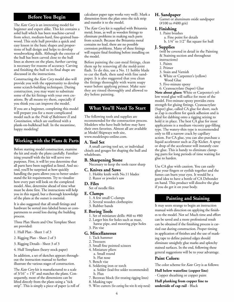
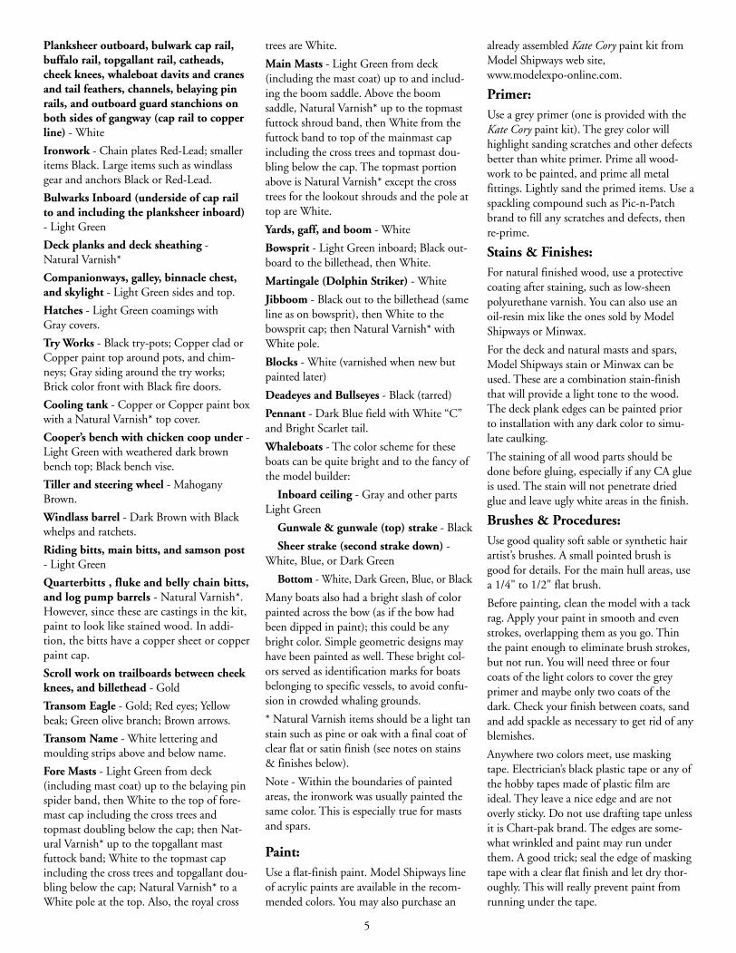
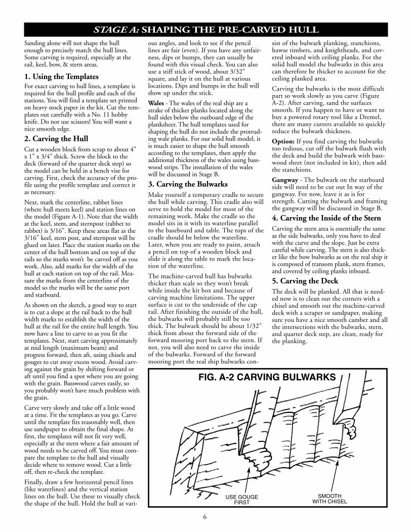

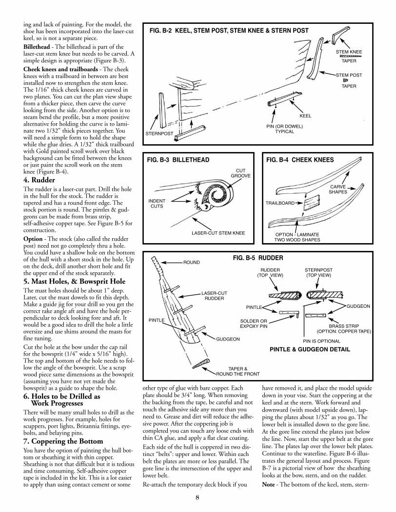
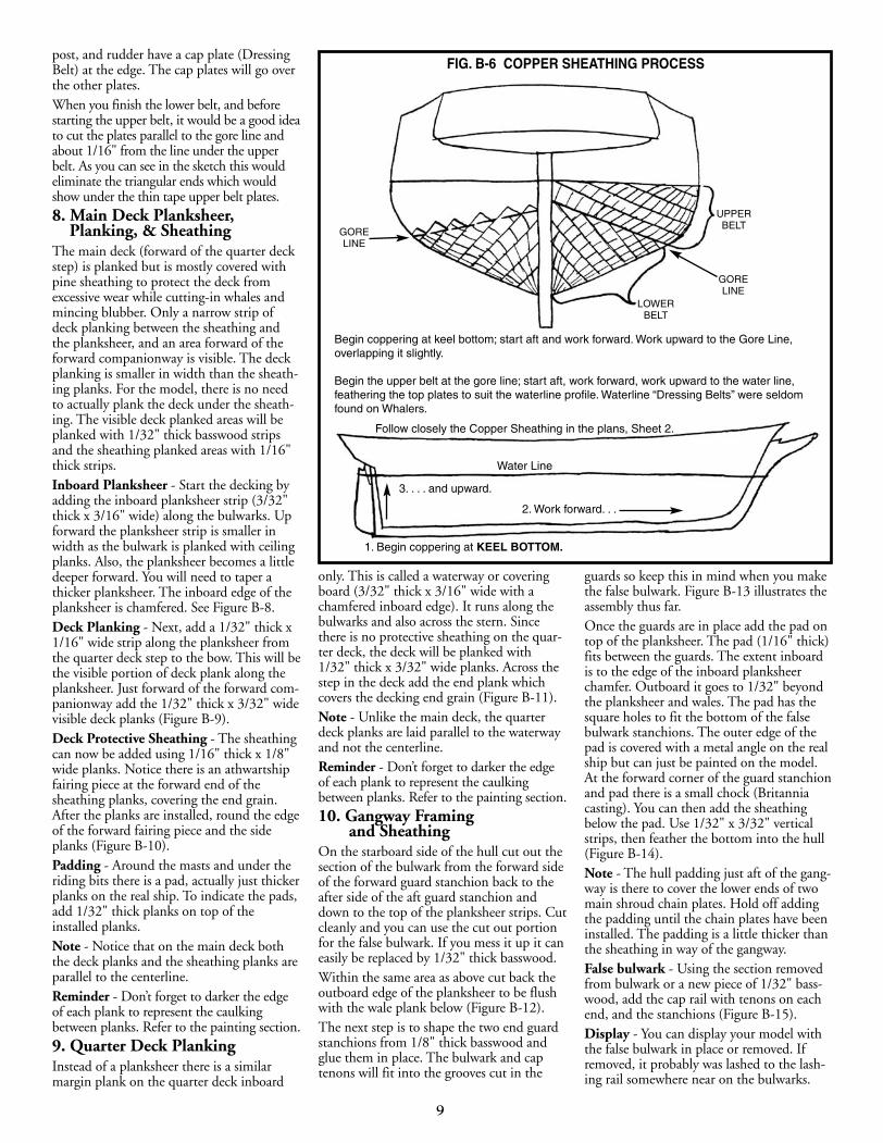

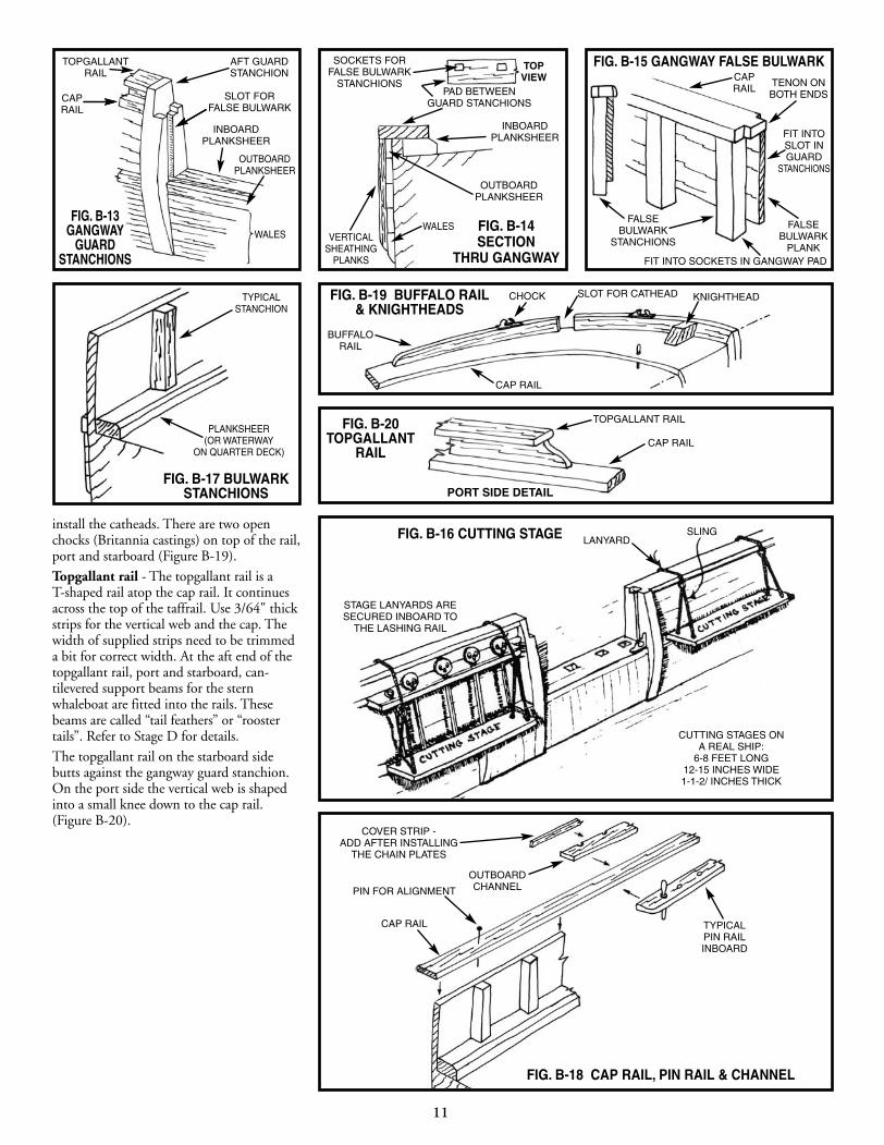

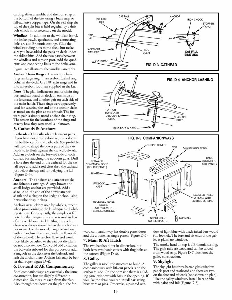
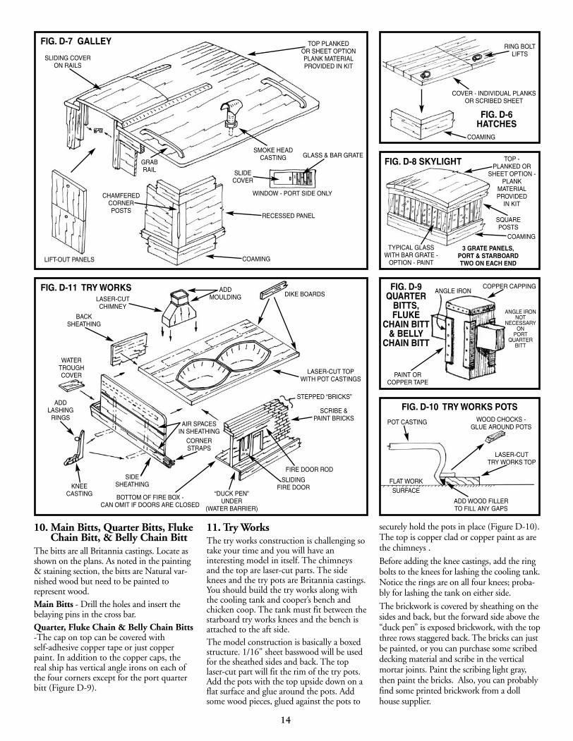
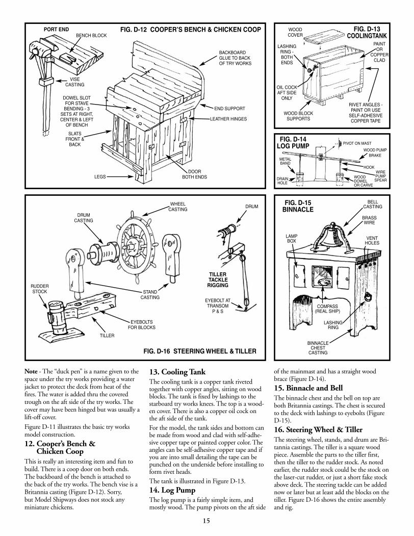
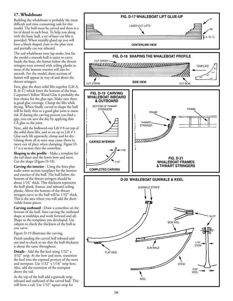


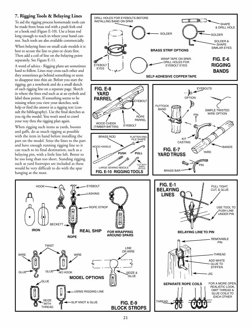

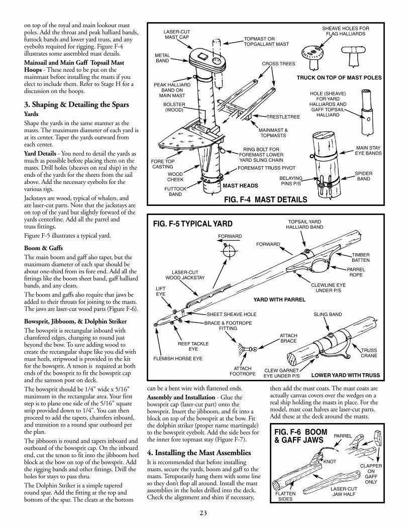
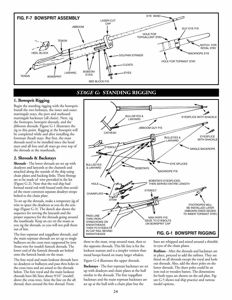

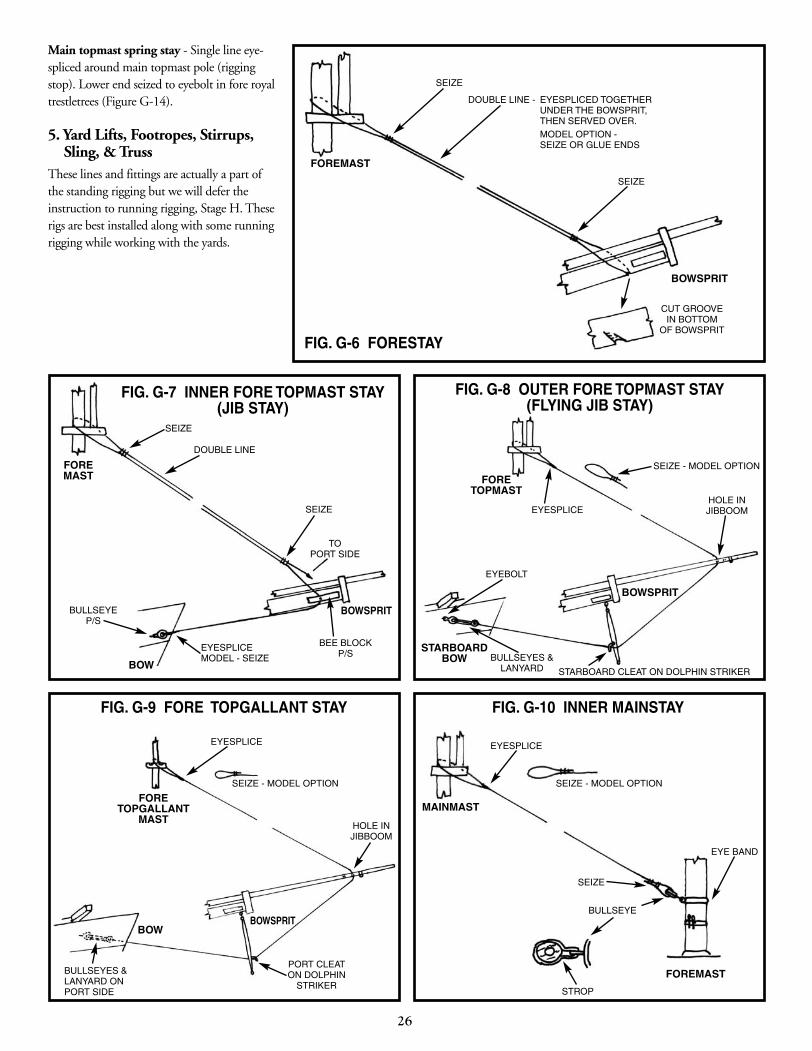
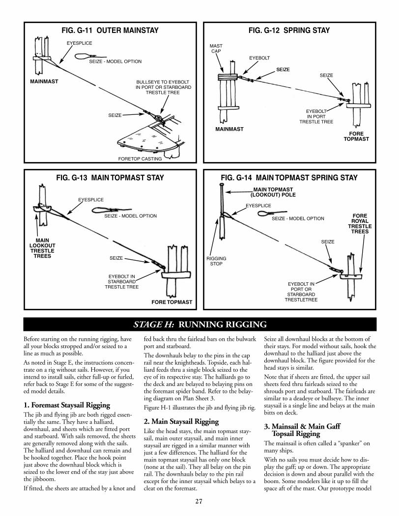
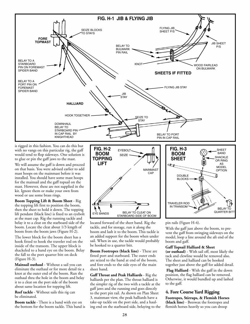

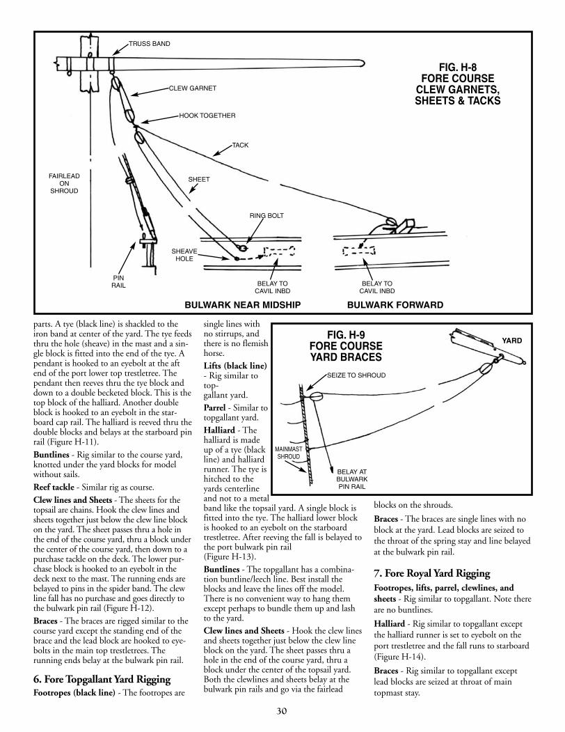
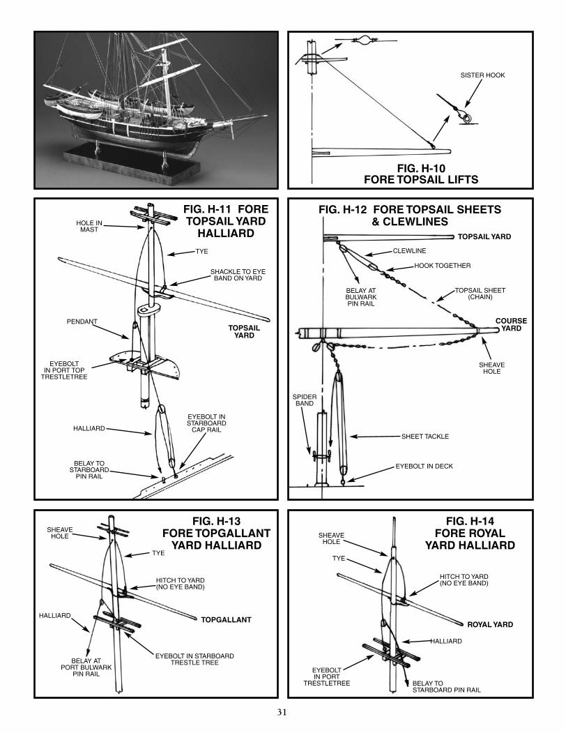
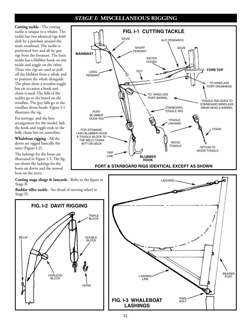


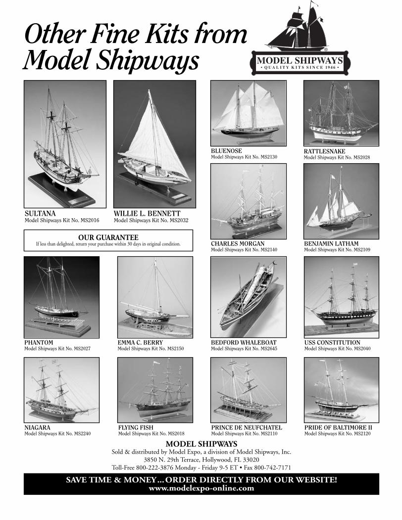


![Model Kartonowy - Fly Model 133 - Sailing Ship Tovarisch[1]](https://static.documents.pub/doc/80x56/55cf9c36550346d033a90c71/model-kartonowy-fly-model-133-sailing-ship-tovarisch1.jpg)
