13
KEYSTONE high performance segmental retaining walls NSW LANDSCAPING COLLECTION 2016 - 17
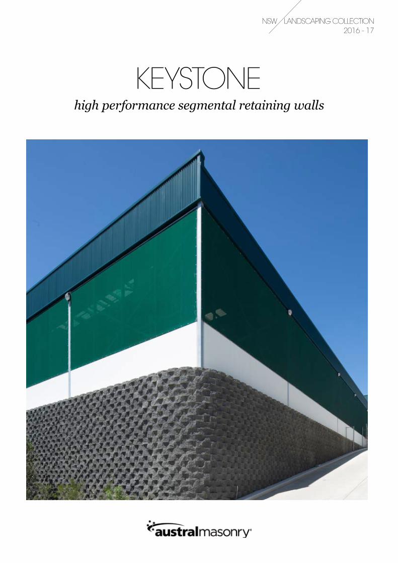
KEYSTONEhigh performance segmental retaining walls
NSW LANDSCAPING COLLECTION 2016 - 17
/ 3 /
AUSTRAL MASONRY KEYSTONE RETAINING WALLS
KEYSTONEEngineered perfection
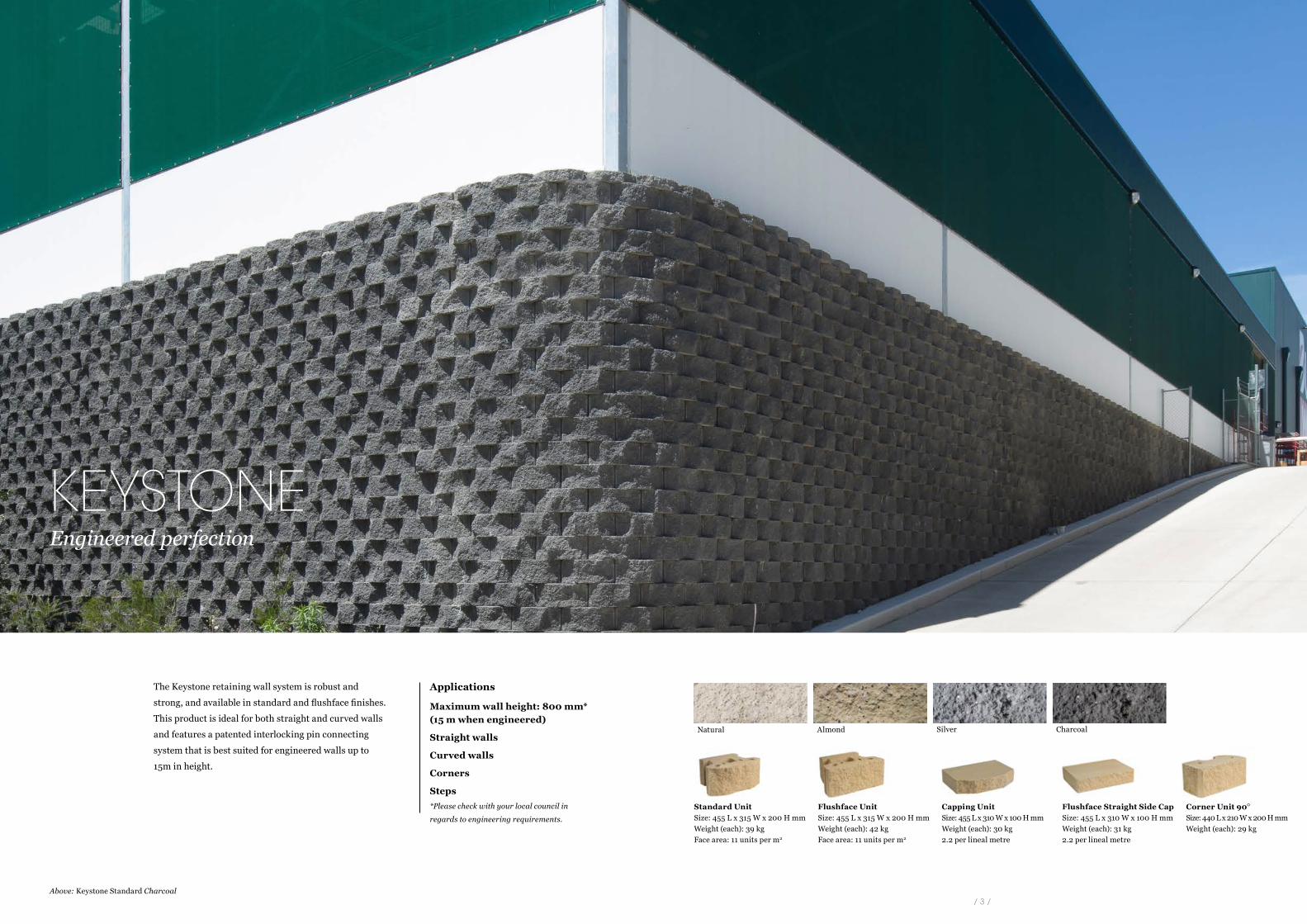
The Keystone retaining wall system is robust and
strong, and available in standard and flushface finishes.
This product is ideal for both straight and curved walls
and features a patented interlocking pin connecting
system that is best suited for engineered walls up to
15m in height.
Above: Keystone Standard Charcoal
Applications
Maximum wall height: 800 mm* (15 m when engineered)
Straight walls
Curved walls
Corners
Steps*Please check with your local council in
regards to engineering requirements.
Natural Almond Silver Charcoal
Standard UnitSize: 455 L x 315 W x 200 H mm Weight (each): 39 kg Face area: 11 units per m2
Flushface Unit Size: 455 L x 315 W x 200 H mm Weight (each): 42 kg Face area: 11 units per m2
Flushface Straight Side Cap Size: 455 L x 310 W x 100 H mm Weight (each): 31 kg 2.2 per lineal metre
Capping Unit Size: 455 L x 310 W x 100 H mm Weight (each): 30 kg 2.2 per lineal metre
Corner Unit 90º Size: 440 L x 210 W x 200 H mm Weight (each): 29 kg
/ 5 /
AUSTRAL MASONRY KEYSTONE RETAINING WALLS
KEYSTONEoverview
Benefits of Keystone Keystone System Components
Keystone Applications
Keystone Construction/Design
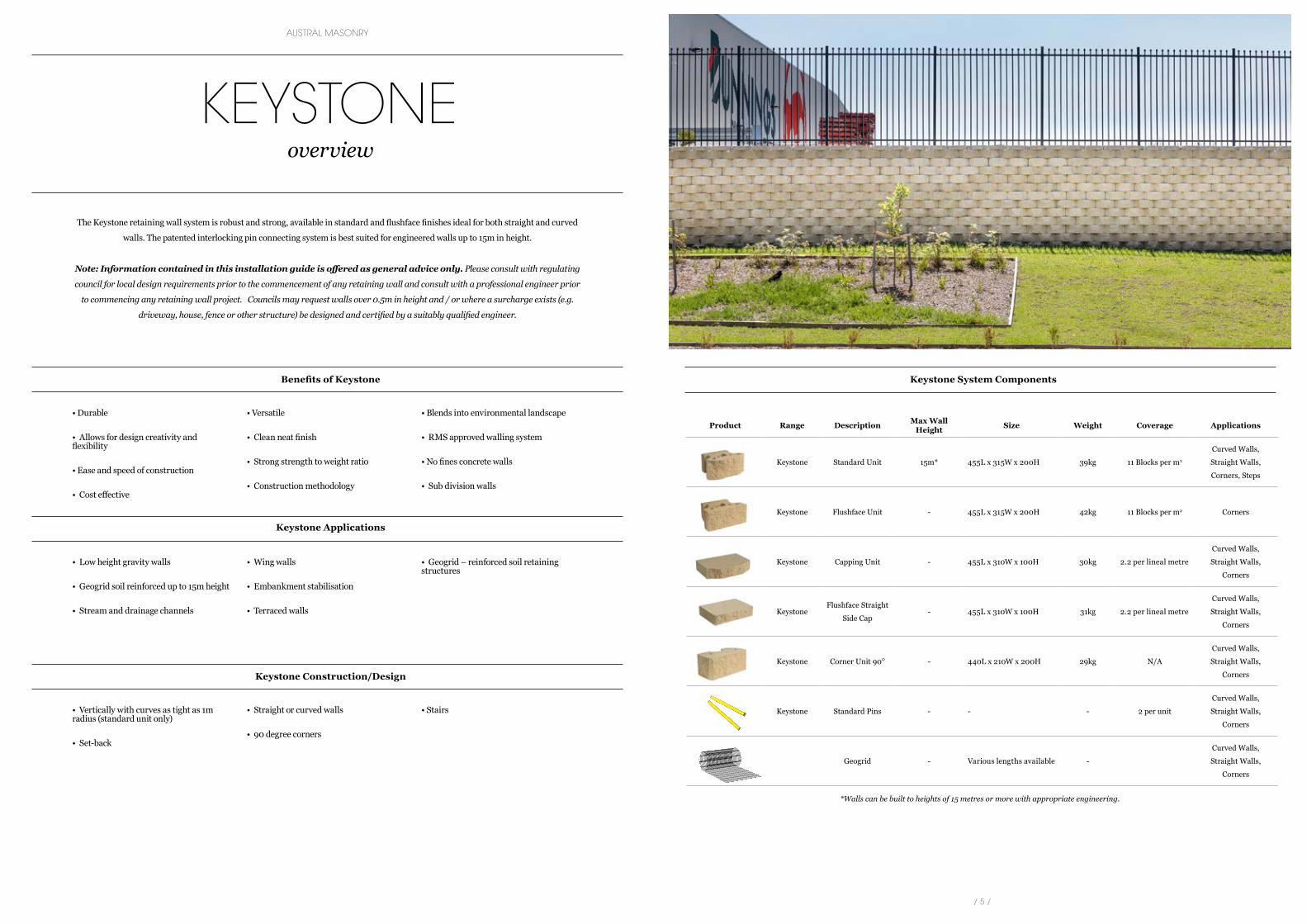
The Keystone retaining wall system is robust and strong, available in standard and flushface finishes ideal for both straight and curved
walls. The patented interlocking pin connecting system is best suited for engineered walls up to 15m in height.
Note: Information contained in this installation guide is offered as general advice only. Please consult with regulating
council for local design requirements prior to the commencement of any retaining wall and consult with a professional engineer prior
to commencing any retaining wall project. Councils may request walls over 0.5m in height and / or where a surcharge exists (e.g.
driveway, house, fence or other structure) be designed and certified by a suitably qualified engineer.
• Durable
• Allows for design creativity and flexibility
• Ease and speed of construction
• Cost effective
• Versatile
• Clean neat finish
• Strong strength to weight ratio
• Construction methodology
• Blends into environmental landscape
• RMS approved walling system
• No fines concrete walls
• Sub division walls
• Low height gravity walls
• Geogrid soil reinforced up to 15m height
• Stream and drainage channels
• Wing walls
• Embankment stabilisation
• Terraced walls
• Geogrid – reinforced soil retaining structures
• Vertically with curves as tight as 1m radius (standard unit only)
• Set-back
• Straight or curved walls
• 90 degree corners
• Stairs
Product Range Description Max Wall Height Size Weight Coverage Applications
Keystone Standard Unit 15m* 455L x 315W x 200H 39kg 11 Blocks per m2
Curved Walls,
Straight Walls,
Corners, Steps
Keystone Flushface Unit - 455L x 315W x 200H 42kg 11 Blocks per m2 Corners
Keystone Capping Unit - 455L x 310W x 100H 30kg 2.2 per lineal metre
Curved Walls,
Straight Walls,
Corners
KeystoneFlushface Straight
Side Cap- 455L x 310W x 100H 31kg 2.2 per lineal metre
Curved Walls,
Straight Walls,
Corners
Keystone Corner Unit 90º - 440L x 210W x 200H 29kg N/A
Curved Walls,
Straight Walls,
Corners
Keystone Standard Pins - - - 2 per unit
Curved Walls,
Straight Walls,
Corners
Geogrid - Various lengths available -
Curved Walls,
Straight Walls,
Corners
Keystone® Specification table
Description Nº/m2 Nominal Unit Wt (kg)
National NSW QLD SA VIC
Standard Unit 11 41 32 34 35
Flushface Unit 11 42 39 N/A 38
Standard Straight Sided Cap 2.2/lin mtr 25 20 20 25
Flushface Straight Sided Cap 2.2/lin mtr 26 23 N/A 26.3
)ssalgerb fi dedurtlup htgnerts hgih( tinu lluf rep snip 2sniP
Lifting Bars Keystone® units should be lifted by two people using the Keystone® lifting bars.
Geogrid As per design requirements
N/A = Not available
National National
Standard Unit 11 36
Flushface Unit 11 39
Standard Straight Sided Cap 2.2/lin mtr 25
Flushface Straight Sided Cap 2.2/lin mtr 26
2sniP pins per full unit, 2 pins per ladder supplied
Lifting Bars Keysteel® units should be lifted by two people using the Keysteel® lifting bars.
Steel Ladders As per design requirements
305
200
455
Standard Unit Flushface Unit
275
100
455
275
100
455
Standard Straight Sided Cap Flushface Straight Sided Cap
Lifting Bars Keygrid Geogrid
Pins
305
200
455
305
200
455
Standard Unit Flushface Unit
310
100
455
310
100
455
Standard Straight Sided Cap Flushface Straight Sided Cap
Steel Pins (hot-dip galvanised) Lifting Bars
Steel Ladders (hot-dip galvanised)
315
20 0
455
Keysteel® Specification table
Description Nº/m2 Nominal Unit Wt (kg)
*Walls can be built to heights of 15 metres or more with appropriate engineering.
/ 6 / / 7 /
AUSTRAL MASONRY KEYSTONE RETAINING WALLS
KEYSTEELoverview
Benefits of Keysteel
Keysteel Applications
Keysteel Construction/Design
Keysteel Specification Table
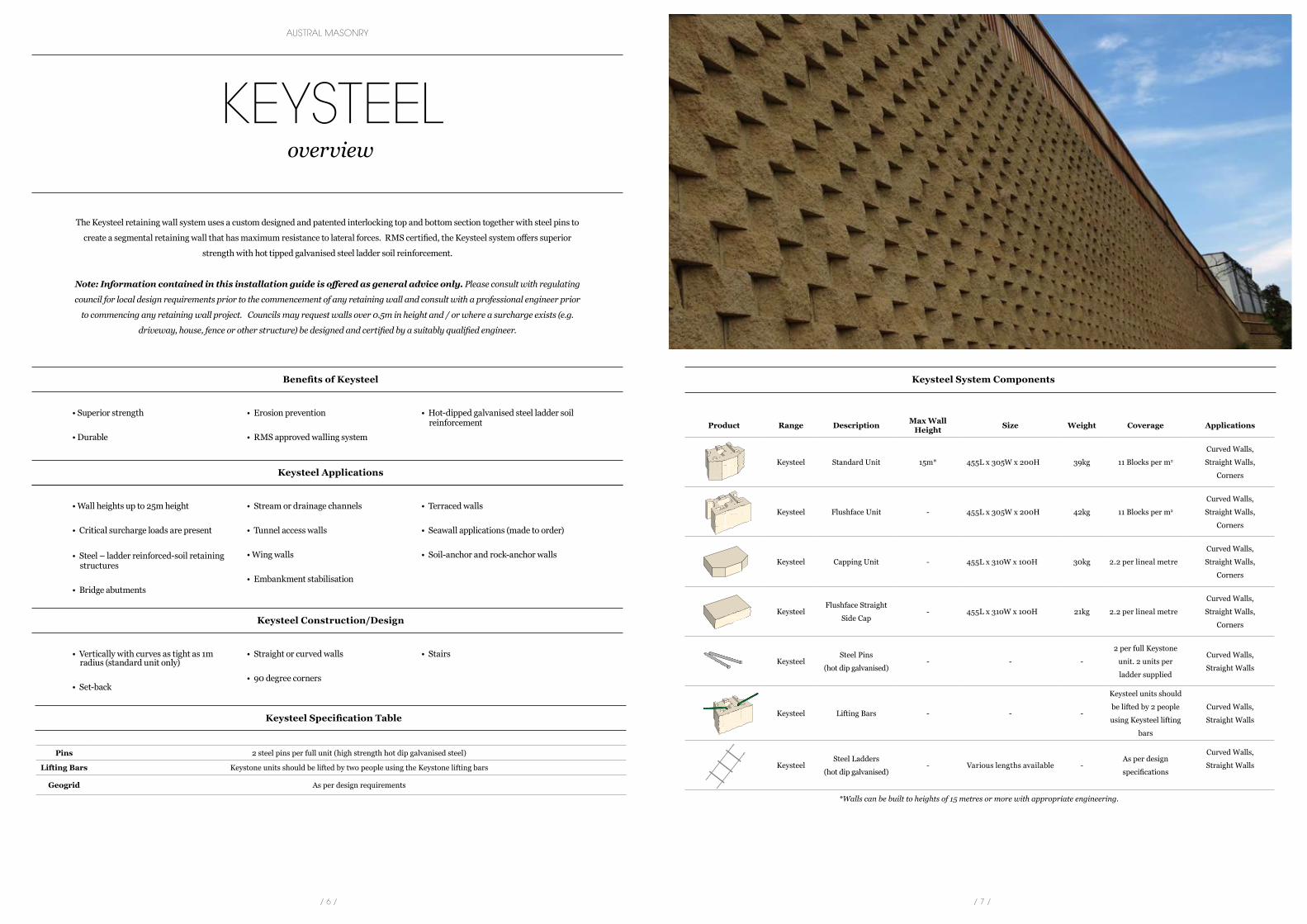
The Keysteel retaining wall system uses a custom designed and patented interlocking top and bottom section together with steel pins to
create a segmental retaining wall that has maximum resistance to lateral forces. RMS certified, the Keysteel system offers superior
strength with hot tipped galvanised steel ladder soil reinforcement.
Note: Information contained in this installation guide is offered as general advice only. Please consult with regulating
council for local design requirements prior to the commencement of any retaining wall and consult with a professional engineer prior
to commencing any retaining wall project. Councils may request walls over 0.5m in height and / or where a surcharge exists (e.g.
driveway, house, fence or other structure) be designed and certified by a suitably qualified engineer.
• Superior strength
• Durable
• Erosion prevention
• RMS approved walling system
• Hot-dipped galvanised steel ladder soil reinforcement
• Wall heights up to 25m height
• Critical surcharge loads are present
• Steel – ladder reinforced-soil retaining structures
• Bridge abutments
• Stream or drainage channels
• Tunnel access walls
• Wing walls
• Embankment stabilisation
• Terraced walls
• Seawall applications (made to order)
• Soil-anchor and rock-anchor walls
• Vertically with curves as tight as 1m radius (standard unit only)
• Set-back
• Straight or curved walls
• 90 degree corners
• Stairs
Pins 2 steel pins per full unit (high strength hot dip galvanised steel)
Lifting Bars Keystone units should be lifted by two people using the Keystone lifting bars
Geogrid As per design requirements
Keysteel System Components
Product Range Description Max Wall Height Size Weight Coverage Applications
Keysteel Standard Unit 15m* 455L x 305W x 200H 39kg 11 Blocks per m2
Curved Walls,
Straight Walls,
Corners
Keysteel Flushface Unit - 455L x 305W x 200H 42kg 11 Blocks per m2
Curved Walls,
Straight Walls,
Corners
Keysteel Capping Unit - 455L x 310W x 100H 30kg 2.2 per lineal metre
Curved Walls,
Straight Walls,
Corners
KeysteelFlushface Straight
Side Cap- 455L x 310W x 100H 21kg 2.2 per lineal metre
Curved Walls,
Straight Walls,
Corners
KeysteelSteel Pins
(hot dip galvanised)- - -
2 per full Keystone
unit. 2 units per
ladder supplied
Curved Walls,
Straight Walls
Keysteel Lifting Bars - - -
Keysteel units should
be lifted by 2 people
using Keysteel lifting
bars
Curved Walls,
Straight Walls
KeysteelSteel Ladders
(hot dip galvanised)- Various lengths available -
As per design
specifications
Curved Walls,
Straight Walls
*Walls can be built to heights of 15 metres or more with appropriate engineering.
/ 9 /
AUSTRAL MASONRY KEYSTONE RETAINING WALLS
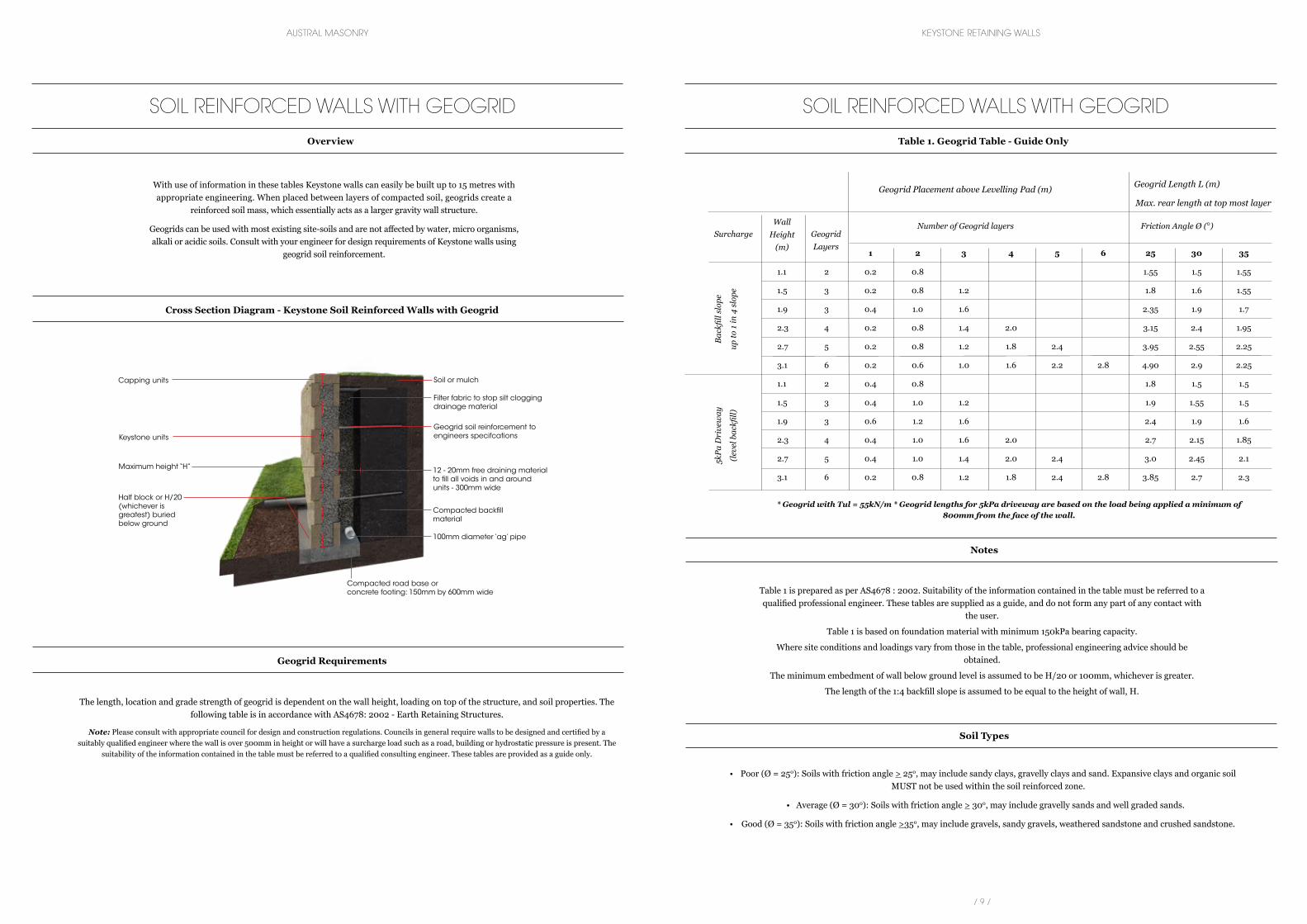
SOIL REINFORCED WALLS WITH GEOGRID
With use of information in these tables Keystone walls can easily be built up to 15 metres with appropriate engineering. When placed between layers of compacted soil, geogrids create a
reinforced soil mass, which essentially acts as a larger gravity wall structure.
Geogrids can be used with most existing site-soils and are not affected by water, micro organisms, alkali or acidic soils. Consult with your engineer for design requirements of Keystone walls using
geogrid soil reinforcement. 1 2 3 4 5 6 25 30 35
1.1 2 0.2 0.8 1.55 1.5 1.55
1.5 3 0.2 0.8 1.2 1.8 1.6 1.55
1.9 3 0.4 1.0 1.6 2.35 1.9 1.7
2.3 4 0.2 0.8 1.4 2.0 3.15 2.4 1.95
2.7 5 0.2 0.8 1.2 1.8 2.4 3.95 2.55 2.25
3.1 6 0.2 0.6 1.0 1.6 2.2 2.8 4.90 2.9 2.25
1.1 2 0.4 0.8 1.8 1.5 1.5
1.5 3 0.4 1.0 1.2 1.9 1.55 1.5
1.9 3 0.6 1.2 1.6 2.4 1.9 1.6
2.3 4 0.4 1.0 1.6 2.0 2.7 2.15 1.85
2.7 5 0.4 1.0 1.4 2.0 2.4 3.0 2.45 2.1
3.1 6 0.2 0.8 1.2 1.8 2.4 2.8 3.85 2.7 2.3
Geogrid Placement above Levelling Pad (m)
Bac
kfill
slop
e
up to
1 in
4 s
lope
5kPa
Dri
vew
ay
(lev
el b
ackfi
ll)
Number of Geogrid layers Friction Angle Ø (º)
Geogrid Length L (m)
Max. rear length at top most layer
Geogrid Layers
Wall Height
(m)
Surcharge
The length, location and grade strength of geogrid is dependent on the wall height, loading on top of the structure, and soil properties. The following table is in accordance with AS4678: 2002 - Earth Retaining Structures.
Note: Please consult with appropriate council for design and construction regulations. Councils in general require walls to be designed and certified by a suitably qualified engineer where the wall is over 500mm in height or will have a surcharge load such as a road, building or hydrostatic pressure is present. The
suitability of the information contained in the table must be referred to a qualified consulting engineer. These tables are provided as a guide only.
Cross Section Diagram - Keystone Soil Reinforced Walls with Geogrid
Geogrid Requirements
SOIL REINFORCED WALLS WITH GEOGRID
Overview Table 1. Geogrid Table - Guide Only
• Poor (Ø = 250): Soils with friction angle > 250, may include sandy clays, gravelly clays and sand. Expansive clays and organic soil MUST not be used within the soil reinforced zone.
• Average (Ø = 300): Soils with friction angle > 300, may include gravelly sands and well graded sands.
• Good (Ø = 350): Soils with friction angle >350, may include gravels, sandy gravels, weathered sandstone and crushed sandstone.
Soil Types
Table 1 is prepared as per AS4678 : 2002. Suitability of the information contained in the table must be referred to a qualified professional engineer. These tables are supplied as a guide, and do not form any part of any contact with
the user.
Table 1 is based on foundation material with minimum 150kPa bearing capacity.
Where site conditions and loadings vary from those in the table, professional engineering advice should be obtained.
The minimum embedment of wall below ground level is assumed to be H/20 or 100mm, whichever is greater.
The length of the 1:4 backfill slope is assumed to be equal to the height of wall, H.
Notes
Compacted road base or concrete footing: 150mm by 600mm wide
Compacted backfillmaterial
100mm diameter ‘ag’ pipe
Half block or H/20 (whichever is greatest) buried below ground
Maximum height “H”
Keystone units
Capping units
12 - 20mm free draining material to fill all voids in and around units - 300mm wide
Geogrid soil reinforcement toengineers specifcations
Filter fabric to stop silt clogging drainage material
Soil or mulch
* Geogrid with Tul = 55kN/m * Geogrid lengths for 5kPa driveway are based on the load being applied a minimum of 800mm from the face of the wall.
/ 10 / / 11 /
AUSTRAL MASONRY KEYSTONE RETAINING WALLS
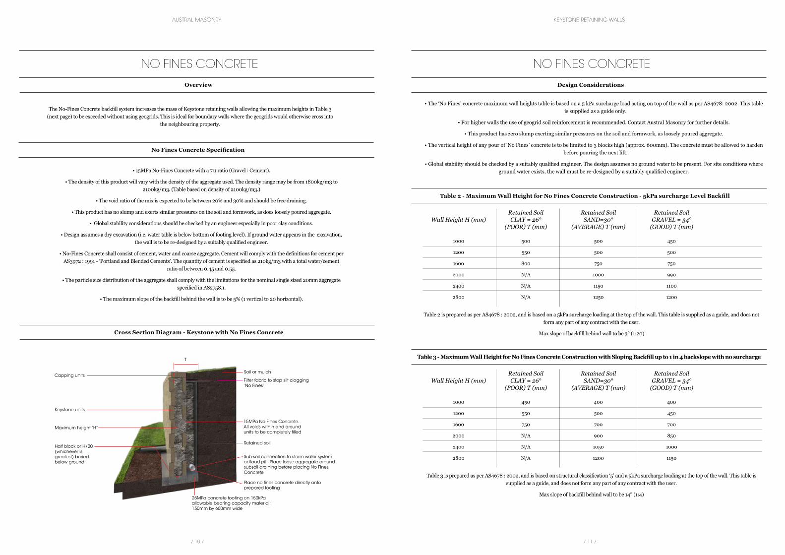
The No-Fines Concrete backfill system increases the mass of Keystone retaining walls allowing the maximum heights in Table 3 (next page) to be exceeded without using geogrids. This is ideal for boundary walls where the geogrids would otherwise cross into
the neighbouring property.
• The ‘No Fines’ concrete maximum wall heights table is based on a 5 kPa surcharge load acting on top of the wall as per AS4678: 2002. This table is supplied as a guide only.
• For higher walls the use of geogrid soil reinforcement is recommended. Contact Austral Masonry for further details.
• This product has zero slump exerting similar pressures on the soil and formwork, as loosely poured aggregate.
• The vertical height of any pour of ‘No Fines’ concrete is to be limited to 3 blocks high (approx. 600mm). The concrete must be allowed to harden before pouring the next lift.
• Global stability should be checked by a suitably qualified engineer. The design assumes no ground water to be present. For site conditions where ground water exists, the wall must be re-designed by a suitably qualified engineer.
Retained Soil Retained Soil Retained Soil Wall Height H (mm) CLAY = 26° SAND=30° GRAVEL = 34° (POOR) T (mm) (AVERAGE) T (mm) (GOOD) T (mm)
1000 500 500 450
1200 550 500 500
1600 800 750 750
2000 N/A 1000 990
2400 N/A 1150 1100
2800 N/A 1250 1200
NO FINES CONCRETE
Overview
NO FINES CONCRETE
Design Considerations
Cross Section Diagram - Keystone with No Fines Concrete
No Fines Concrete Specification
Table 2 - Maximum Wall Height for No Fines Concrete Construction - 5kPa surcharge Level Backfill
• 15MPa No-Fines Concrete with a 7:1 ratio (Gravel : Cement).
• The density of this product will vary with the density of the aggregate used. The density range may be from 1800kg/m3 to 2100kg/m3. (Table based on density of 2100kg/m3.)
• The void ratio of the mix is expected to be between 20% and 30% and should be free draining.
• This product has no slump and exerts similar pressures on the soil and formwork, as does loosely poured aggregate.
• Global stability considerations should be checked by an engineer especially in poor clay conditions.
• Design assumes a dry excavation (i.e. water table is below bottom of footing level). If ground water appears in the excavation, the wall is to be re-designed by a suitably qualified engineer.
• No-Fines Concrete shall consist of cement, water and coarse aggregate. Cement will comply with the definitions for cement per AS3972 : 1991 - ‘Portland and Blended Cements’. The quantity of cement is specified as 210kg/m3 with a total water/cement
ratio of between 0.45 and 0.55.
• The particle size distribution of the aggregate shall comply with the limitations for the nominal single sized 20mm aggregate specified in AS2758.1.
• The maximum slope of the backfill behind the wall is to be 5% (1 vertical to 20 horizontal).
25MPa concrete footing on 150kPa allowable bearing capacity material: 150mm by 600mm wide
Place no fines concrete directly onto prepared footing
Retained soil
Sub-soil connection to storm water system or flood pit. Place loose aggregate around subsoil draining before placing No Fines Concrete
Half block or H/20 (whichever is greatest) buried below ground
Maximum height “H”
Keystone units
Capping units
15MPa No Fines Concrete.All voids within and around units to be completely filled
Soil or mulch
T
Filter fabric to stop silt clogging ‘No Fines’
Table 2 is prepared as per AS4678 : 2002, and is based on a 5kPa surcharge loading at the top of the wall. This table is supplied as a guide, and does not form any part of any contract with the user.
Max slope of backfill behind wall to be 3º (1:20)
Retained Soil Retained Soil Retained Soil Wall Height H (mm) CLAY = 26° SAND=30° GRAVEL = 34° (POOR) T (mm) (AVERAGE) T (mm) (GOOD) T (mm)
1000 450 400 400
1200 550 500 450
1600 750 700 700
2000 N/A 900 850
2400 N/A 1050 1000
2800 N/A 1200 1150
Table 3 - Maximum Wall Height for No Fines Concrete Construction with Sloping Backfill up to 1 in 4 backslope with no surcharge
Table 3 is prepared as per AS4678 : 2002, and is based on structural classification ‘5’ and a 5kPa surcharge loading at the top of the wall. This table is supplied as a guide, and does not form any part of any contract with the user.
Max slope of backfill behind wall to be 14º (1:4)
/ 12 / / 13 /
AUSTRAL MASONRY KEYSTONE RETAINING WALLS
Step 1: Excavation/Preparation of Levelling Pad
Excavate a trench 600mm wide and sufficiently deep to allow a levelling base of 150mm +25mm height for each course. Place 25MPa concrete (non-reinforced) to form the footing.
Step 2: Installing the first course
Half block or H/20 (whichever is greatest) of the block should be buried below ground. Lay the first course of units side to side over the prepared base, with the 12mm pinholes on top. Maintain the 305mm distance between pinhole centres of adjacent units. In straight walls,
units will touch. In concave or convex curves, the units will overlap or require spacing to maintain the 305mm pin distance.
Step 3: Installing the pins
Place two Keystone fibreglass connecting pins into each unit. Use the front holes for a vertical wall (corners and curved walls). Use the rear holes for a 1 in 8 setback (i.e. for every course the wall will set back 25mm). For straight walls only.
Step 4: No Fines Concrete Backfill
Backfill the wall with No-Fines Concrete. All voids inside and between the units must also be filled. The vertical height of any pour of No-Fines Concrete is limited to 600mm. Each pour must be allowed to harden prior to pouring the next lift. Alternatively the wall may be propped.
Step 5: Additional Courses
Sweep the top of the previous course of units clean of any loose no fines concrete. Place the next course of units so that the kidney holes fit over the pins of the two units below. Pull the unit towards the face of the wall until it locks with the pins on both sides. Repeat Steps 3 and 4.
Step 6: Installing Capping Units
Lay capping units, backfill and compact to required grade. It is recommended that the capping units be secured using masonry construction adhesive or epoxy cement.
NO FINES CONCRETE
Construction Steps
/ 14 / / 15 /
AUSTRAL MASONRY KEYSTONE RETAINING WALLS
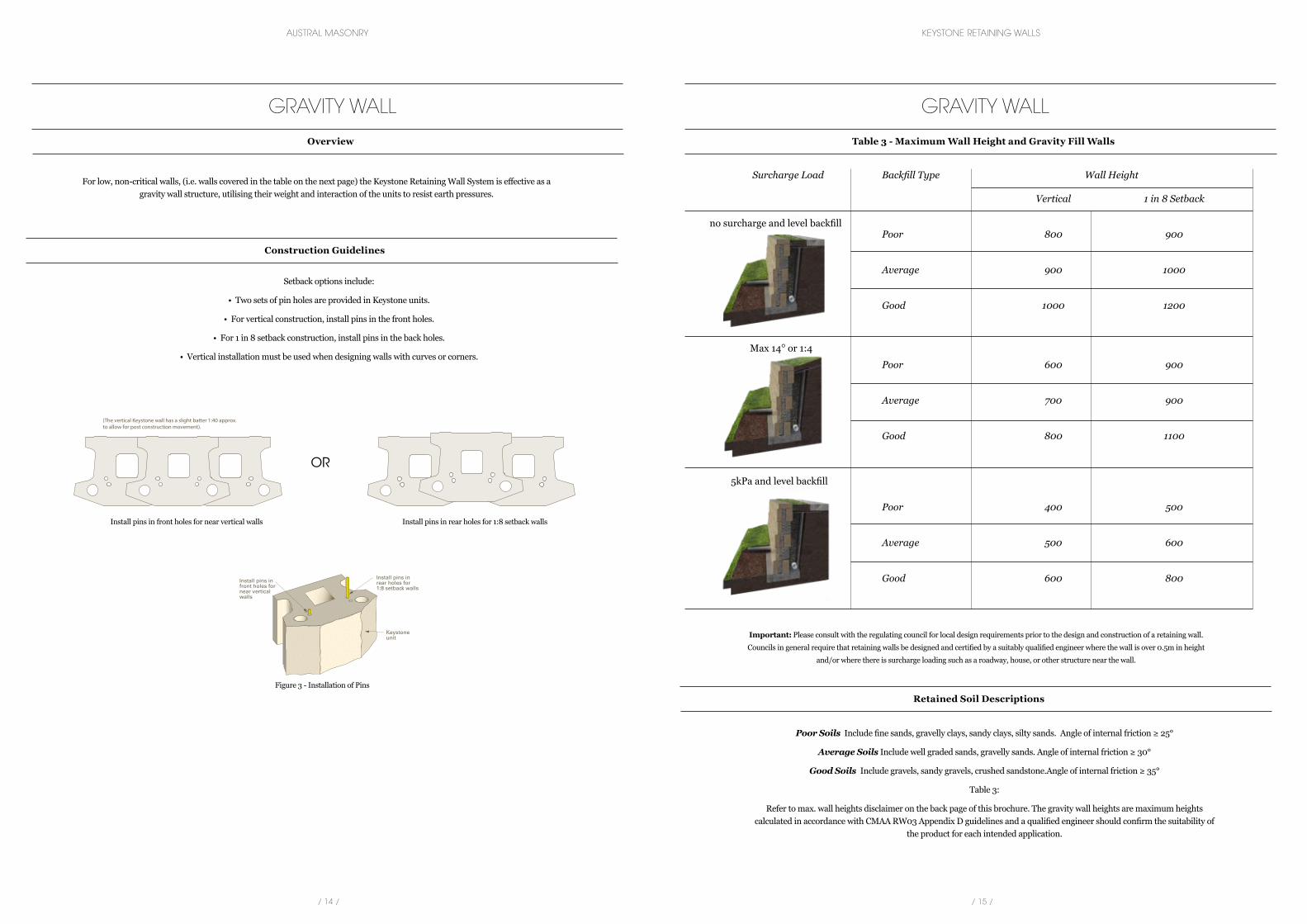
For low, non-critical walls, (i.e. walls covered in the table on the next page) the Keystone Retaining Wall System is effective as a gravity wall structure, utilising their weight and interaction of the units to resist earth pressures.
Setback options include:
• Two sets of pin holes are provided in Keystone units.
• For vertical construction, install pins in the front holes.
• For 1 in 8 setback construction, install pins in the back holes.
• Vertical installation must be used when designing walls with curves or corners.
GRAVITY WALL
Overview
Construction Guidelines
Retained Soil Descriptions
Poor Soils Include fine sands, gravelly clays, sandy clays, silty sands. Angle of internal friction ≥ 25°
Average Soils Include well graded sands, gravelly sands. Angle of internal friction ≥ 30°
Good Soils Include gravels, sandy gravels, crushed sandstone.Angle of internal friction ≥ 35°
Table 3:
Refer to max. wall heights disclaimer on the back page of this brochure. The gravity wall heights are maximum heights calculated in accordance with CMAA RW03 Appendix D guidelines and a qualified engineer should confirm the suitability of
the product for each intended application.
Important: Please consult with the regulating council for local design requirements prior to the design and construction of a retaining wall.
Councils in general require that retaining walls be designed and certified by a suitably qualified engineer where the wall is over 0.5m in height
and/or where there is surcharge loading such as a roadway, house, or other structure near the wall.
GRAVITY WALL
Table 3 - Maximum Wall Height and Gravity Fill Walls
Figure 3 — Installation of Pins
Table 3 - Maximum Wall Height for Gravel-Fill Walls
Surcharge Loading Backfi ll Type
Wall Height H (mm)
Vertical 1 in 8Setback
Poor 800 900
Average 900 1000
Good 1000 1200
Poor 600 900
Average 700 900
Good 800 1100
Poor 400 500
Average 500 600
Good 600 800
No Su
rcharg
e Loa
ding
15° S
loped
Back
�llDr
ivewa
y/Carp
ark Lo
ading
(5kP
a)
(The vertical Keystone wall has a slight batter 1:40 approx.to allow for post construction movement).
No load
1 : 3
5kPa
OR
Max 14º or 1:4
no surcharge and level backfill
5kPa and level backfill
Surcharge Load Backfill Type Wall Height
Vertical 1 in 8 Setback
Poor 800 900
Average 900 1000
Good 1000 1200
Poor 600 900
Average 700 900
Good 800 1100
Poor 400 500
Average 500 600
Good 600 800
Install pins in front holes for near vertical walls
Figure 3 - Installation of Pins
Install pins in rear holes for 1:8 setback walls
/ 16 / / 17 /
AUSTRAL MASONRY KEYSTONE RETAINING WALLS
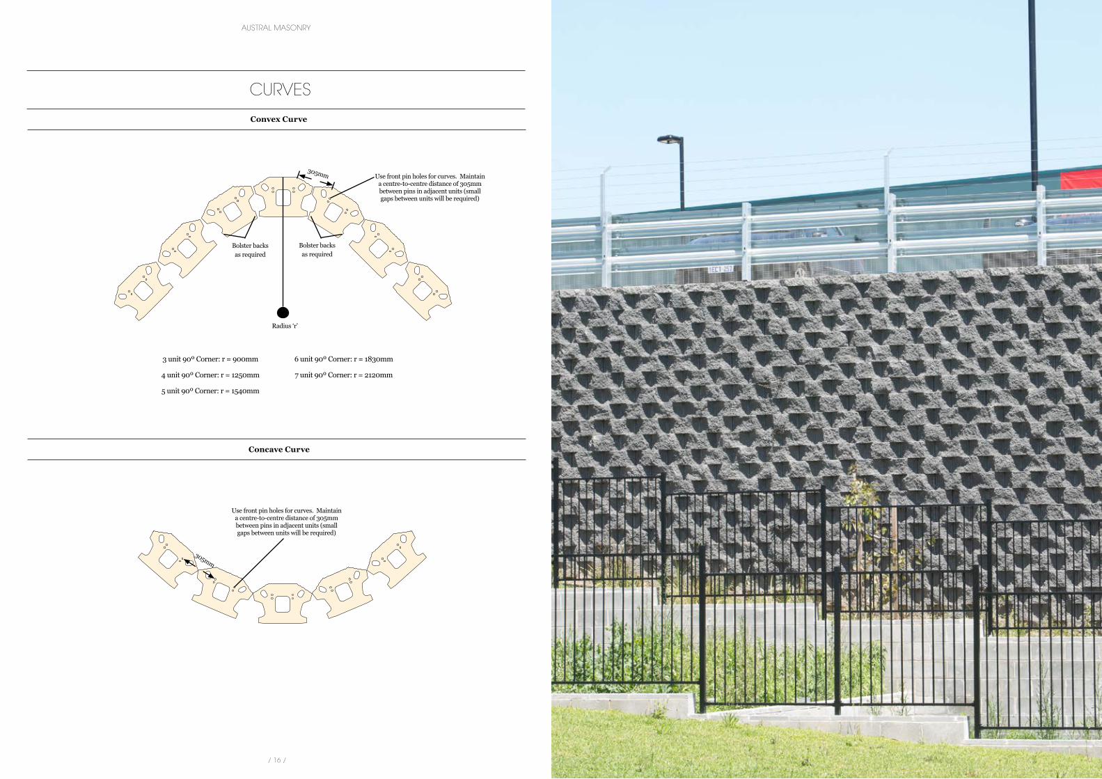
3 unit 90º Corner: r = 900mm
4 unit 90º Corner: r = 1250mm
5 unit 90º Corner: r = 1540mm
6 unit 90º Corner: r = 1830mm
7 unit 90º Corner: r = 2120mm
CURVES
Convex Curve
Concave Curve
Radius ‘r’
Bolster backs as required
Bolster backs as required
Use front pin holes for curves. Maintain a centre-to-centre distance of 305mm between pins in adjacent units (small gaps between units will be required)
Use front pin holes for curves. Maintain a centre-to-centre distance of 305mm between pins in adjacent units (small gaps between units will be required)
305mm
305mm
/ 18 / / 19 /
AUSTRAL MASONRY KEYSTONE RETAINING WALLS
1. Scope of Work
1.1 Extent
This specification covers the works for construction of seg-mental, reinforced-soil retaining structures. The works include footing excavation, foundation preparation, drainage, backfill and compaction and related items necessary to complete the
work indicated on drawings and as further specified.
All retaining wall construction is to be carried out in accor-dance with the levels, distances and details as shown on the
drawings and in accordance with this specification.
The Keystone reinforced retaining wall system shall also be constructed in accordance with the manufacturers installation guidelines by a suitably qualified and experienced contractor.
1.2 Responsibilities
The Contractor shall be responsible for carrying out the instal-lation of all retaining walls in accordance with this specification
and the associated contract documents.
2. Standard Specification
Wherever reference is made to Standards Association of Australia (SAA) the requirements of the editions and amend-ments, shall apply to the relevant materials or operations and
be deemed to be incorporated in this specification.
In the case of a conflict between the referenced standard spec-ification and code and this specification, the more stringent
provisions shall apply.
The following is a summary of standard specifications applica-ble to this subsection of the work:
AS1012 Methods of Testing Concrete
AS4456 Concrete Masonry Units
AS3600 Concrete Structures
AS4456.4 Masonry Units — Compressive Strength
AS4678 Earth Retaining Structures
AS1289 Methods of Testing Soils
Materials or operations not covered by the above standard codes shall conform to the appropriate Australian Standard.
3. General Requirements
3.1 General
Terms used in this specification shall have the meanings as-signed to them as follows:
‘Approved’ shall mean approved in writing by the Engineer. ‘Or equal approved’ shall mean equivalent in performance, quality
and price to that specified and approved by the Engineer.
Where limits to the properties of soils are defined elsewhere herein these properties shall be determined by the methods
laid down in AS1289.
The term ‘construction area’ in this Part shall be defined as an area to be excavated or an area to be cleared and filled.
3.2 Regulations
The Contractor shall comply with all relevant Acts, Regulations and By-Laws in respect of all work specified herein, including temporary timbering, strutting, guard rails and all safety mea-
sures to be adopted.
3.3 Certification
The Contractor’s Geotechnical Engineer shall certify that the bearing capacity of the foundation is as per the foundation requirements specified on the drawings. The Geotechnical Engineer shall also inspect and certify that the Reinforced
Soil Block material is as specified on drawings with regard to friction angle, and bulk density.
4. Materials
4.1 Masonry Units
The retaining wall units shall be manufactured in accordance with AS4456 Concrete Masonry Units. Block types and sizes for Keystone retaining walls shall be as shown on the drawings or
specified herein.
4.1.1 Tolerance
Permissible tolerance in the manufacture of retaining wall units shall comply with AS4456.3 - 1997. In the case of Keystone units, the tolerance of ± 2mm shall not apply to profiled or
textured faces. Non conforming concave distortions shall be rejected.
4.1.2 Strength
Retaining wall units shall be manufactured with a minimum compressive strength of 10MPa. A minimum of ten (10)
samples must be tested to obtain a mean compressive strength, tested to failure as per AS4456.4 — 2003 under normal com-
pressive and laboratory conditions.
4.1.3 Colour
The colour and texture of masonry units shall be as specified and shall remain consistent with the ‘sample range’ approved
by the project Superintendent.
4.1.4 Handling/Storage/Delivery
Keystone units shall be delivered on pallets to minimise damage during transportation. The Contractor shall store and handle
units so as to prevent units from damage, which may affect the aesthetic quality or structural integrity of the finished wall.
4.2 Connecting Pins
High strength pultruded fibreglass pins shall be used to inter-lock and align all Keystone units in a running bond pattern. Pins shall also provide an integral connection between the
Keystone units and the geogrid.
4.3 Geogrids
The reinforcing elements for the reinforced soil structure shall be as shown on the drawings.
If required, each consignment of geogrids delivered to site shall be accompanied by a Quality Control Tensile Test Certificate
from the manufacturer.
4.4 Approved Reinforced Soil Block Backfill
Material for backfilling between geogrids for the Keystone retaining wall shall be ‘Approved Backfill’ defined as sand,
crushed sandstone or broken rock obtained from excavations or approved borrow areas. Such material shall be
• Free of rock fragments greater than 75mm in size.
• Free of clay lumps retained on a 75mm sieve.
• Free of organic matter.
• Within the following grading requirements;
Sieve Size % Passing by Weight
75mm - 100%
26.5mm - 50 - 100%
4.75mm - 25 - 75%
0.425mm - 10 - 50%
0.075mm - 0 - 20%
• Non-plastic in that the fraction passing 0.425mm has a Plas-ticity Index of not greater than 15.
• Capable of being brought to a moisture content suitable for compaction as specified elsewhere herein, under the weather
conditions prevailing on site.
The ‘Approved Backfill’ shall be stockpiled on site, and in-spected and approved by the Geotechnical Engineer that the material satisfies the specification above the design friction
angle and dry density values as specified on drawings. Testing for dry density and friction angle shall be in accordance with
section 6 herein.
4.5 Drainage
All retaining walls are to contain drainage systems that prevent the build up of hydrostatic pressure behind walls. This is to include a 12-20mm free draining clean hard aggregate, used to fill all voids within the retaining wall units and to extend
300mm behind the units.
Drainage is to be installed as per the drawings and as per the manufacturers recommendations.
4.6 Concrete Works
All concrete for use in footings for retaining walls shall have a compressive strength after 28 days of 25MPa unless specified
otherwise.
The supply, placement, finishing and curing of reinforcement and insitu concrete shall comply in every respect with AS3600.
4.7 Hold and Witness Points
The following shall be deemed a Hold Point:
• Submission of test results and samples of all retaining wall components.
The following shall be deemed a Witness Point:
• On-site slump and strength testing of concrete.
5. Construction of Keystone Retaining Walls
5.1 Foundations
Excavation is to be to the lines and grades shown on the drawings. The reinforced soil block foundation size shall be
constructed as per drawings unless alterations are made by the Geotechnical Engineer, who may require tests on the sub-grade
material, to be carried out by a registered N.A.T.A. Testing Laboratory.
The reinforced soil block foundation subgrade shall be proof rolled with a heavy steel drum roller (minimum applied
intensity of 4t/m width of drum with at least 8 passes) without vibration. Any material which is soft, visibly deformed, un-
stable or deemed unsuitable by the Contractor’s geotechnical consultant shall be excavated and replaced with approved fill and compacted to achieve dry densities of between 98% and
103% of Standard Maximum Dry Density at moisture content of ±2% of Standard Optimum Moisture Content.
The foundation shall be inspected and approved by the Geo-technical Engineer, who shall verify that the foundation bearing capacity exceeds the required bearing capacity as specified on drawings. The approval of the reinforced soil block foundation
shall be deemed a HOLD POINT.
Detailed excavation for the mass concrete footing shall proceed following acceptance of the foundation. The footing subgrade shall be inspected by the Contractor’s Geotechnical Engineer
and any areas deemed soft, unstable or unsuitable by the Geotechnical Engineer shall be excavated and replaced as
described above.
The footing shall be constructed as shown on the drawings. It could be shown as compacted roadbase or concrete. For
concrete, the footing shall be poured to the correct level using formwork edge boards, or other methods which ensure the cor-
KEYSTONE RETAINING WALLS
Typical Specifications
KEYSTONE RETAINING WALLS
Typical Specifications
/ 20 / / 21 /
AUSTRAL MASONRY KEYSTONE RETAINING WALLS
KEYSTONE RETAINING WALLS
Typical Specifications
rect level of the footing. The concrete footing shall be screeded flat. The level of the footing or first course of blocks shall be
verified by survey methods, and approved by the Contractors QA representative. This shall be deemed a WITNESS POINT.
5.2 Unit Installation
Foundations and all courses are laid level. Batters are achieved by inserting the fibreglass connecting pins into the appropriate holes. The Keystone retaining walls shall be constructed with
batters as shown on the drawings.
First course of units shall be placed side by side on the base levelling pad. Units shall be levelled side to side and front to
back and checked for alignment. The accurate placement of the first course is most important, to ensure acceptable horizontal and vertical tolerances. Two fibreglass connecting pins shall be inserted into the appropriate holes to interlock and align units.
The front set of pin holes shall be used for near vertical setback.The rear pair of holes shall be used for 25mm (1:8) setback. All voids in units and between units shall be filled with drainage fill as specified in section 4.5. Drainage fill shall extend to 300mm
behind units.
Units shall be placed in a running bond pattern. Top of units shall be swept clean of excess material. Kidney holes of units above shall be positioned over pins in units below. Units shall be pulled toward the face of the wall to interlock the pins with units on either side. Levels and alignment of each course shall
be checked. Each course shall be filled, backfilled and compact-ed prior to placement of the next course. The Keystone wall shall be surveyed for vertical level tolerance every 3 courses.
This shall be deemed a HOLD POINT.
5.3 Drainage Installation
The drainage measures shall be installed as shown on draw-ings. 100mm diameter agricultural pipe shall be used for
subsoil drainage behind the first course of Keystone units. The subsoil drain shall be placed with a minimum 1% fall as shown
on drawings.
‘T’ piece connection fittings shall be used at all outflow points to connect the subsoil drainage to a 100mm diameter pipe stub
which extends 300mm past the face of the Keystone wall.
The pipe stub material shall be UPVC or HDPE and shall be approved by the project Superintendent.
The outflow points shall be at a maximum of 60m centres. The locations of the outflow points shall be determined by the Superintendent. The outflow pipe stub shall be supported on
the concrete footing, and shall pass between two Keystone units with 60mm of the facing removed by sawcutting. The gap above the pipe in the first course shall be neatly patched with
cement mortar.
The drainage measures shall be inspected by the QA repre-sentative after the installation of the first and second course is complete. Inspection and approval of the drainage installation
shall be deemed a HOLD POINT.
5.4 Placement of Geogrid
The Geogrid shall be placed between Keystone units as spec-ified on the drawings. Geogrids shall be cut to the required
length. Geogrids may be longer than required, but shall not be shorter than the specified length shown on the drawings. The Geogrids shall be placed with the roll direction perpendicular
to the face of the Keystone wall. Correct orientation of the geogrids shall be verified by the Contractor.
After compaction, the layer of select backfill below each geog-rid, shall be raked to a depth of 25mm to ensure good interlock between the geogrid and the select backfill. The Geogrid shall
be laid horizontally on compacted backfill and connected to the Keystone units by hooking geogrid over the fibreglass pins. The geogrid shall be pulled taut against pins to eliminate slack from connections and loose folds. The back edge shall be staked or secured prior to backfilling to maintain tension in the geogrid. Each block shall be checked for level accuracy, as out of posi-tion transverse bars will lead to sloping blocks. If the course
above a layer of geogrid is found to be not level, then the blocks shall be removed, and the geogrid repositioned to ensure it is
level.
For a straight length of wall, the geogrids shall be laid side by side without joints or overlaps. Where the wall is convex, the geogrids shall not be cut, but shall be overlapped with a
minimum of 75mm of compacted fill between them. For a con-cave wall the position of the layers of grid shall be alternated
between consecutive geogrid layers to cover the triangular gaps between strips of geogrid. Refer to Fig 5.4.
The QA Representative shall inspect and keep records of the position of grid and the type of grid placed for each layer of
geogrid. The number of courses between each successive layer of geogrid shall be noted. The QA Representative shall also
check this. This shall be deemed a WITNESS POINT.
5.5 Placement of Reinforced Soil Backfill
Prior to placement of ‘Approved Backfill’ in the reinforced soil block, the Geotechnical Engineer shall approve the material
and confirm that the friction angle and dry density of the material is in accordance with the drawings for that particular section of the project. This shall be deemed a HOLD POINT.
All backfill imported or otherwise shall be as specified on the drawings. Backfill shall be spread in a maximum of 200mm
layers, in such a manner that minimises the voids directly under-neath the geogrid. Fill should be deposited using suitable plant
which causes fill to cascade onto geogrids. Placement of fill on top of the geogrids shall start from the wall face and work back from
the wall face in order to minimise slack or loss of pretension from the grid. Care should be taken to not mix the reinforced soil block
backfill material with the drainage material. If backfill material mixes with the drainage material, then the drainage material is to
be removed and replaced with clean material.
Compaction shall be to 98% of Standard Maximum Dry Density. Compaction shall start at the wall face and work back from the wall face. Compaction testing shall be in accordance with section 6 specified herein. Compaction testing shall be
deemed a WITNESS POINT.
Tracked construction equipment shall not be operated directly on the geogrid. A minimum thickness of 150mm of backfill ma-terial shall be placed prior to the operation of tracked construc-
tion equipment. Rubber tyred equipment may passover the geogrids at very slow speeds. Sudden braking or sharp turning
shall be avoided to prevent displacement of geogrids.
Construction plant and all other vehicles having a mass ex-ceeding 1000kg shall be kept at least 1m from the back of the
Keystone units. Compaction of the 1m zone behind the
Keystone units shall be restricted to:
• Vibrating rollers with a mass < 1000kg
• Vibrating plate compacters with a mass < 1000kg
• Vibro tampers having a mass < 75kg
Surface drainage during and after construction of the wall shall be provided to minimise water infiltration in the reinforced soil zone.
5.6 Hold and Witness Points
The following shall be deemed a HOLD POINT:
• Approval of foundation material by the Geotechnical Engineer.
• Inspection and approval of ‘Approved Backfill’ for use in reinforced soil block by the Geotechnical Engineer.
• Survey of the Keystone Wall every 3 courses.
• Inspection and approval of the drainage installation by the QA Representative.
The following shall be deemed a WITNESS POINT:
• Survey verification that the first course is installed at the correct level, and inspection and approval of footing by the QA
Representative.
• Inspection of level and type of geogrid at each layer by the QA Representative.
• Compaction Testing by the Geotechnical Engineer.
6. Material Testing
6.1 Testing of ‘Approved Backfill’
Each source of ‘Approved Backfill’ shall be pretreated by 5 cycles of repeated compaction, and then tested for dry density and friction angle. Material for use as ‘approved backfill’ shall
be inspected and approved for use by the Geotechnical Engi-neer. A stockpile at least equivalent to 5 days reinforced soil
wall construction shall be maintained on site at all times.
This will allow time for friction angle testing of the approved backfill should visual inspection of the material when it is re-
ceived on site indicate that testing is required. Notwithstanding the above the following minimum testing shall be carried out:
• Dry Density shall be tested at a frequency of 1 test per 400m³ of approved backfill.
• Friction angle shall be tested at a frequency of 1 test per 2000m³ of approved backfill.
If the dry density results are not within ±5% of the specified de-sign value, then the Engineer shall be notified, and the material
not approved for use until the design has been verified.
6.2 Testing for Compaction
Compaction will be checked by standard maximum dry density test and field density test for materials other than sand or by the density index and field density tests for sands as specified
on drawings and herein.
Tests will be carried out in groups of at least three, and com-paction of the layer concerned will be considered to be satisfac-tory if no single result falls outside the specified density range. Should the results not reach this standard the Sub-Contractor shall again roll the area, if necessary after scarifying, adding
water, blading to reduce the moisture content and/or removing and replacing excessively moist fill as may be required.
Should the Geotechnical Engineer consider that the depth of insufficiently compacted material is greater than can be effec-tively compacted from the surface, material shall be removed
to a depth at which compaction is satisfactory and replaced and compacted in 200mm maximum layers.
The standard maximum dry density referred to herein for ma-terials other than sand shall be maximum standard dry density as determined in accordance with AS1289 - Test numbers 5.1.1.
The modified maximum dry density referred to herein for materials other than sand shall be the maximum modified dry density as determined in accordance with AS1289 - Test 5.2.1.
The field density referred to herein for all materials shall be the dry density of the material in place as determined in accor-
dance with AS1289 - Test 5.3.1.
The percentage of the standard maximum dry density (Dry Density Ratio) elsewhere herein for materials other than sand
shall be calculated from the formula given in AS1289.5.4.1.
The maximum and minimum densities of cohesionless materials shall be determined in accordance with AS1289 - Test E5.1.
The Density Index specified elsewhere herein for sands shall be calculated from the formula given in AS1289.E6.1.
KEYSTONE RETAINING WALLS
Typical Specifications
/ 22 / / 23 /
AUSTRAL MASONRY KEYSTONE RETAINING WALLS
6.3 Frequency of Testing
The following testing frequencies relate to acceptance on a ‘not-one-to-fail’ basis. The testing should be carried out in
essentially randomly chosen locations and at the frequencies as given below. However, it may be appropriate to undertake
testing in specific locations, based on visual appearance or past experience.
Where a test or group of tests is carried out on an area which has been subjected to essentially the same preparation and
compaction procedures, the whole of this area is considered to be represented by this test or group of tests. The uniform area is generally known as a work lot. On this basis, if one or more tests indicate compliance with the specification has not been achieved,
the whole of the area which has been submitted for testing is deemed not to comply, unless it can be demonstrated that the
area in which the non-complying test result(s) can reasonably be separated from the whole. It should not be assumed a test result
applies only to the area immediately surrounding it.
Required frequency of testing, is not less than 1 test per layer of 200 mm thickness per material type per 400m³ which is 1 test per layer per 100 linear metres of wall construction. If different
sources of ‘approved backfill’ are used within the 100 linear metre work lot, then 1 test per type of material is required. If the work is staged in sections of less than 100 linear metres,
then 1 test per section is required.
The testing frequency may be re-assessed to the approval of the Engineer, if a high degree of uniformity becomes evident
during construction.
KEYSTONE RETAINING WALLS
Typical Specifications
STEPS
Keystone Step Details
Sand: Cement = 6:1
Compacted bedding sand
160mm riser
100mm40mm
10mm
Bedding sand - compacted before laying treads
Keystone flushface caps
10mm mortar join
40mm pavers
Tread approx. 290mmfor 40mm pavers
SEA WALL
Construction Details
Compacted aggregate or concrete levelling pad: 150mm by 600mm wide
Nonwoven filter fabric
Compacted backfillmaterial
Half to one block buried below ground to engineers specifications
Maximum height “H”
Keystone units
150 - 200mm rip-rap
Capping units
free draining material less than 10% passing the #20 sieve.No organic material. Width to engineers specifications
Geogrid soil reinforcement toengineers specifcations
Filter fabric to stop silt clogging drainage material
Soil or mulch

STYLE WITH SUBSTANCE
australbricks.com.au | 13-brick
The product images in our brochures give a general indication of colour for your preliminary selection.
Partners in Design 03/2016
Austral Bricks is part of the Brickworks Group
DESIGN STUDIO
DESIGN CENTRES
HEAD OFFICE
Sydney CBD
Ground Floor, 50 Carrington Street, Sydney NSW 2000
Albion Park
45 Princes Highway, Albion Park NSW 2527
2 Yangan Drive,
NSW 2322
Bowral
Brikscape Pty Ltd. Lot 1 Oxleys Hill Road, Bowral NSW 2576
27 Lawson Street
NSW 2450
Punchbowl
62 Belmore Rd North, Punchbowl NSW 2196
Tuggerah
MD Brick 19 Bryant Drive, Tuggerah NSW 2259
Canberra
7 Lithgow Street, Fyshwick ACT 2609
Horsley Park
738-780 Wallgrove Rd, Horsley Park NSW 2175
STYLE AND FUNCTION
OFFICE LOCATIONS
Coffs Harbour
27 Lawson Crescent Coffs Harbour NSW 2450
Tel: +61 2 6652 3457 Fax: +61 2 6651 4367 E: [email protected]
Horsley Park
3 Latitude Road Horsley Park NSW 2175
Tel: +61 2 9840 2333 Fax: +61 2 9840 2344 E: [email protected]
www.australmasonry.com.au
1300 masonry (1300 627 667)
1. Stock colours. Colours other than stock colours are made to order. Contact your nearest Austral Masonry office for your area’s stock colours. A surcharge applies to orders less than the set minimum quantity. 2. Colour and texture variation. Colour variation can and will occur between product batches despite efforts to ensure extensive efforts to ensure colour consistency. This can
be caused by the supply of raw materials can vary over time. In addition, variation can occur between product types and production batches. 3. We reserve the right to change the details in this publication without notice. 4. For a full set of Terms & Conditions of Sale please contact your nearest Austral Masonry sales office.
5. Important Notice. Please consult with your local council for design regulations prior to the construction of your wall. Councils in general require those walls over 0.5m in height and/or where there is loading such as a car or house near the wall be designed and certified by a suitably qualified engineer. 6. Max wall heights disclaimer. The gravity wall heights are maximum heights
calculated in accordance with CMAA MA-53 Appendix D guidelines and a qualified engineer should confirm the suitability of the product for each application. As such, due consideration must be given to but not limited to: Cohesion. Dry backfill, no ingress of any water into the soil behind the retaining wall. All retaining walls are designed for zero surcharge unless noted otherwise.
These walls are intended for structure Classification A walls only as defined in AS4678 Earth Retaining Structures as being where failure would result in minimal damage and/or loss of access. The product images shown in this brochure give a general indication of product colour for your preliminary selection. Austral Masonry recommends all customers see actual product samples at
a selection centre prior to making final selections.
Proud Supporters


