Kinectrack: Agile 6-DoF Tracking Using a Projected Dot Pattern Paul McIlroy * University of Cambridge Microsoft Research Shahram Izadi † Microsoft Research Andrew Fitzgibbon ‡ Microsoft Research ABSTRACT We present Kinectrack, a new six degree-of-freedom (6-DoF) tracker which allows real-time and low-cost pose estimation using only commodity hardware. We decouple the dot pattern emitter and IR camera of the Kinect. Keeping the camera fixed and moving the IR emitter in the environment, we recover the 6-DoF pose of the emitter by matching the observed dot pattern in the field-of-view of the camera to a pre-captured reference image. We propose a novel matching technique to obtain dot pattern correspondences ef- ficiently in wide- and adaptive-baseline scenarios. We also propose an auto-calibration method to obtain the camera intrinsics and dot pattern reference image. The performance of Kinectrack is evalu- ated and the rotational and translational accuracy of the system is measured relative to ground truth for both planar and multi-planar scene geometry. Our system can simultaneously recover the 6-DoF pose of the device and also recover piecewise planar 3D scene struc- ture, and can be used as a low-cost method for tracking a device without any on-board computation, with small size and only simple electronics. 1 I NTRODUCTION 6-DoF trackers are the backbone of augmented reality (AR), bridg- ing the gap between real and virtual coordinate frames. A tremen- dous variety of approaches exist: some use hardware such as inertial measurement units, others are computer vision based. Some com- puter vision approaches “look in” on the object to be tracked whilst others “look out” to infer the object’s pose from observations of its surroundings [6, 10, 21]. Each approach has its own strengths and limitations in terms of cost, accuracy, robustness, form factor and on-device power consumption. In this paper we present a low-cost solution using only commodity hardware that provides accurate and robust real-time tracking with minimal hardware on the object to be tracked. Like “look in” methods, the tracking device requires no on-board computation or communication with the host; like “look out” methods, it offers high rotational accuracy. Figure 1 illustrates the essential components of our system. An infrared (IR) dot-pattern emitter, specifically the laser diffractive optical element (DOE) from a Kinect, casts a large number of pseudo-randomly arranged rays into an arbitrary 3D scene, and these rays are observed by an IR camera. Knowing the dot pattern (the reference) allows the rotation and translation of the emitter to be determined relative to the camera, even without knowing the 3D geometry of the scene, and even if that geometry is changing over time. Our system is designed to be a cheaper alternative to fixed cam- era 6-DoF trackers (such as the Vicon motion capture system). The system is orders of magnitude lower cost than commercially avail- able systems, can work with a single camera (although it scales to larger camera setups) and requires only a cheap and small form- * e-mail: [email protected]† e-mail: [email protected]‡ e-mail: [email protected]Figure 1: Tracking setup. (Left) A fixed camera, and free moving laser-pattern emitter provides the benefits of “look out” tracking, but the moving device is very simple—a laser, optics, and battery—and can be considerably smaller than “look in” remotes. (Right) The laser and optics of the remote unit. In practice, an infrared laser would be used; a visible-light unit is used here purely for illustration. factor emitter on each tracked object. Our contributions in this pa- per are twofold: • A new 6-DoF tracking system for AR called Kinectrack, with advantages over existing systems as outlined above. • A general-purpose matching algorithm for projected dot pat- terns: a form of “variable baseline” matching for dot projec- tion systems. 2 BACKGROUND There has been a great deal of research that has explored 3D pose estimation of handheld devices for a variety of interactive scenar- ios including AR. Here we focus on vision-based trackers as most other technologies (e.g. inertial [29]) can be combined somewhat orthogonally with vision. Perhaps some of the best known tracking techniques, exempli- fied by the commercial Vicon [25] and OptiTrack [17] systems, have used multiple fixed IR cameras and active diffuse IR illumi- nation of the scene to localize retro-reflective markers placed on objects. These markers show up as a bright signal in the 2D IR camera images, and their 3D position can be derived through tri- angulation. Positioning multiple markers on an object enables 3D rotation to be computed. Whilst highly accurate in 3D translation, these systems are costly and require effort to set up and calibrate the infrastructure. To achieve high rotation accuracy for AR applica- tions, the markers on the roaming unit need to be spaced sufficiently far apart, which can considerably increase the physical size of the roaming unit. Williams and Fitzgibbon [27] address this problem using a hologram to provide a large change in appearance for a small change in orientation, inspiring our current work. The reverse of the “look in” setup is to keep the marker fixed in space and instead move a single camera to recover 6-DoF pose. These marker-based technologies [9, 7, 24, 23] have been adopted in a variety of AR applications, and can now even be supported on mobile phones. A variety of marker designs have been investi- gated including pseudo-random dot patterns [24]. However, these systems suffer from the need for careful placement of the marker
Transcript
Kinectrack: Agile 6-DoF Tracking Using a Projected Dot PatternPaul McIlroy∗
University of CambridgeMicrosoft Research
Shahram Izadi†
Microsoft ResearchAndrew Fitzgibbon‡
Microsoft Research
ABSTRACT
We present Kinectrack, a new six degree-of-freedom (6-DoF)tracker which allows real-time and low-cost pose estimation usingonly commodity hardware. We decouple the dot pattern emitter andIR camera of the Kinect. Keeping the camera fixed and moving theIR emitter in the environment, we recover the 6-DoF pose of theemitter by matching the observed dot pattern in the field-of-viewof the camera to a pre-captured reference image. We propose anovel matching technique to obtain dot pattern correspondences ef-ficiently in wide- and adaptive-baseline scenarios. We also proposean auto-calibration method to obtain the camera intrinsics and dotpattern reference image. The performance of Kinectrack is evalu-ated and the rotational and translational accuracy of the system ismeasured relative to ground truth for both planar and multi-planarscene geometry. Our system can simultaneously recover the 6-DoFpose of the device and also recover piecewise planar 3D scene struc-ture, and can be used as a low-cost method for tracking a devicewithout any on-board computation, with small size and only simpleelectronics.
1 INTRODUCTION
6-DoF trackers are the backbone of augmented reality (AR), bridg-ing the gap between real and virtual coordinate frames. A tremen-dous variety of approaches exist: some use hardware such as inertialmeasurement units, others are computer vision based. Some com-puter vision approaches “look in” on the object to be tracked whilstothers “look out” to infer the object’s pose from observations of itssurroundings [6, 10, 21]. Each approach has its own strengths andlimitations in terms of cost, accuracy, robustness, form factor andon-device power consumption. In this paper we present a low-costsolution using only commodity hardware that provides accurate androbust real-time tracking with minimal hardware on the object tobe tracked. Like “look in” methods, the tracking device requires noon-board computation or communication with the host; like “lookout” methods, it offers high rotational accuracy.
Figure 1 illustrates the essential components of our system. Aninfrared (IR) dot-pattern emitter, specifically the laser diffractiveoptical element (DOE) from a Kinect, casts a large number ofpseudo-randomly arranged rays into an arbitrary 3D scene, andthese rays are observed by an IR camera. Knowing the dot pattern(the reference) allows the rotation and translation of the emitter tobe determined relative to the camera, even without knowing the 3Dgeometry of the scene, and even if that geometry is changing overtime.
Our system is designed to be a cheaper alternative to fixed cam-era 6-DoF trackers (such as the Vicon motion capture system). Thesystem is orders of magnitude lower cost than commercially avail-able systems, can work with a single camera (although it scales tolarger camera setups) and requires only a cheap and small form-
Figure 1: Tracking setup. (Left) A fixed camera, and free movinglaser-pattern emitter provides the benefits of “look out” tracking, butthe moving device is very simple—a laser, optics, and battery—andcan be considerably smaller than “look in” remotes. (Right) The laserand optics of the remote unit. In practice, an infrared laser would beused; a visible-light unit is used here purely for illustration.
factor emitter on each tracked object. Our contributions in this pa-per are twofold:
• A new 6-DoF tracking system for AR called Kinectrack, withadvantages over existing systems as outlined above.
• A general-purpose matching algorithm for projected dot pat-terns: a form of “variable baseline” matching for dot projec-tion systems.
2 BACKGROUND
There has been a great deal of research that has explored 3D poseestimation of handheld devices for a variety of interactive scenar-ios including AR. Here we focus on vision-based trackers as mostother technologies (e.g. inertial [29]) can be combined somewhatorthogonally with vision.
Perhaps some of the best known tracking techniques, exempli-fied by the commercial Vicon [25] and OptiTrack [17] systems,have used multiple fixed IR cameras and active diffuse IR illumi-nation of the scene to localize retro-reflective markers placed onobjects. These markers show up as a bright signal in the 2D IRcamera images, and their 3D position can be derived through tri-angulation. Positioning multiple markers on an object enables 3Drotation to be computed. Whilst highly accurate in 3D translation,these systems are costly and require effort to set up and calibrate theinfrastructure. To achieve high rotation accuracy for AR applica-tions, the markers on the roaming unit need to be spaced sufficientlyfar apart, which can considerably increase the physical size of theroaming unit. Williams and Fitzgibbon [27] address this problemusing a hologram to provide a large change in appearance for asmall change in orientation, inspiring our current work.
The reverse of the “look in” setup is to keep the marker fixedin space and instead move a single camera to recover 6-DoF pose.These marker-based technologies [9, 7, 24, 23] have been adoptedin a variety of AR applications, and can now even be supportedon mobile phones. A variety of marker designs have been investi-gated including pseudo-random dot patterns [24]. However, thesesystems suffer from the need for careful placement of the marker
before use, line-of-sight and occlusion issues, inaccuracies in track-ing, and sensitivities to lighting. Systems have explored the use ofprojecting multiple fixed IR markers [4, 28] to resolve some of theissues of lighting and occlusions, the converse of our arrangement.
Removing the need for markers altogether, simultaneous local-ization and mapping (SLAM) systems [6, 10] obtain pose frommarkers naturally occurring in the scene, and, for applications in-volving video overlays, can use just one camera. Both SLAM andour method require a form of infrastructure: the scene. SLAMimposes the additional constraint that the scene is sufficiently tex-tured. Our method only requires that the scene provide quasi-planarpatches for matching and therefore also works for scenes dominatedby textureless surfaces. SLAM is suitable for free AR as the sensinghardware moves with the user. Our method requires a fixed camera,which dictates the working volume, but in return offers drift-free,absolute 6-DoF pose per frame, even when the scene geometry ischanging over time. Camera placement is flexible and setup is fast.
Several systems have been proposed which track laser pointersas interaction devices. In many instances, these are essentially 2-DoF trackers [3, 5, 1]. Higher degrees of freedom have been ex-plored including roll [20] and the 3-DoF of a 1D projective trans-form [14]. Closely related to our work are 6-DoF trackers based onray projectors. The “Sceptre” system of Wienss et al. [26] projectsa 7-point pattern shaped like an “F”. Our system differs in that theprojected pattern has a much wider footprint, and we can match asmall subset of the pattern while obtaining accurate pose. Usinga wide-angle projector beam and requiring only a small fragmentof the project pattern to be in view at each frame permits a muchgreater range of emitter poses and provides tolerance to occlusion,non-planar scenes, and varying surface albedo. A multiple cam-era implementation would provide full 360◦ pose if required. Thematching problem with the 7-point system is simpler than ours, soallows matching of multiple overlapping patterns, which we havenot demonstrated. Latoschik and Bomberg [13] describe a systemwhich projects a regular grid onto a planar surface. Although thisgives some improved accuracy, it still requires that the central rayof the grid is visible in every frame, making it intolerant to chang-ing albedo or occlusion. Albitar et al. [2] propose a pattern designto facilitate matching by a structured light coding approach. Ourmatching method works with any pseudo-random dot pattern.
2.1 Wide-baseline dot pattern matching
The key to our approach is essentially the problem of establish-ing correspondence between two views of a large set of pseudo-randomly arranged 3D points. In the case where the correspon-dence is induced by a simple transformation such as a similaritytransformation or homography, researchers have previously devisedhashing schemes for point-pattern lookup.
Kolomenkin et al. [11] address the “lost in space” problem ofmatching an astronomical image into a reference star chart in orderto recover the attitude of a spacecraft using a camera mounted onthe spacecraft. The camera image in this case is related to the refer-ence by a similarity transform, with unknown two-dimensional ro-tation, translation and scale. The proposed solution uses a geomet-ric hashing approach with two stars used to form a canonical frameand the positions of a further two stars within this space providinga hash code. Lang et al. [12] solve for a similarity transform forearth-based cameras by computing invariants of four-point “quads”of points. As they require only a similarity invariant, they generatea four-valued vector for each quad, and index the vectors in a k-Dtree, enabling precise lookup. Nakai et al. [16] use affine invari-ants of subsets of the nearest-neighbour graph to match documentimages in a large database. They look at the n nearest neighboursof each point, and compute invariants for each subset of size m toprovide robustness to missing points.
Our work is very much inspired by these techniques, but we
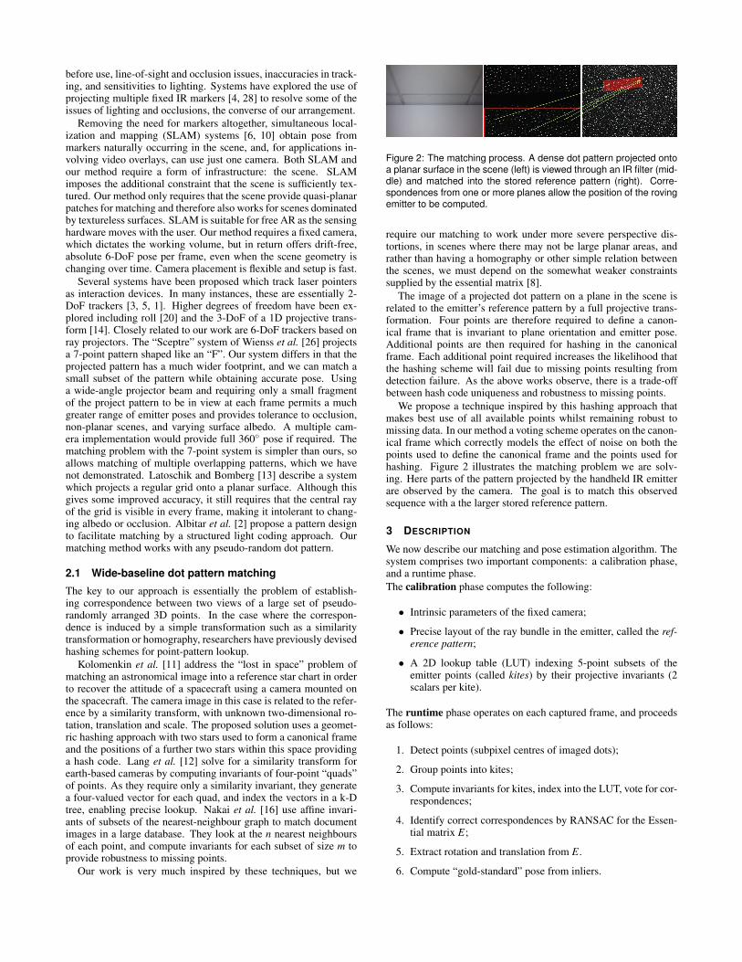
Figure 2: The matching process. A dense dot pattern projected ontoa planar surface in the scene (left) is viewed through an IR filter (mid-dle) and matched into the stored reference pattern (right). Corre-spondences from one or more planes allow the position of the rovingemitter to be computed.
require our matching to work under more severe perspective dis-tortions, in scenes where there may not be large planar areas, andrather than having a homography or other simple relation betweenthe scenes, we must depend on the somewhat weaker constraintssupplied by the essential matrix [8].
The image of a projected dot pattern on a plane in the scene isrelated to the emitter’s reference pattern by a full projective trans-formation. Four points are therefore required to define a canon-ical frame that is invariant to plane orientation and emitter pose.Additional points are then required for hashing in the canonicalframe. Each additional point required increases the likelihood thatthe hashing scheme will fail due to missing points resulting fromdetection failure. As the above works observe, there is a trade-offbetween hash code uniqueness and robustness to missing points.
We propose a technique inspired by this hashing approach thatmakes best use of all available points whilst remaining robust tomissing data. In our method a voting scheme operates on the canon-ical frame which correctly models the effect of noise on both thepoints used to define the canonical frame and the points used forhashing. Figure 2 illustrates the matching problem we are solv-ing. Here parts of the pattern projected by the handheld IR emitterare observed by the camera. The goal is to match this observedsequence with a the larger stored reference pattern.
3 DESCRIPTION
We now describe our matching and pose estimation algorithm. Thesystem comprises two important components: a calibration phase,and a runtime phase.The calibration phase computes the following:
• Intrinsic parameters of the fixed camera;
• Precise layout of the ray bundle in the emitter, called the ref-erence pattern;
• A 2D lookup table (LUT) indexing 5-point subsets of theemitter points (called kites) by their projective invariants (2scalars per kite).
The runtime phase operates on each captured frame, and proceedsas follows:
1. Detect points (subpixel centres of imaged dots);
2. Group points into kites;
3. Compute invariants for kites, index into the LUT, vote for cor-respondences;
4. Identify correct correspondences by RANSAC for the Essen-tial matrix E;
5. Extract rotation and translation from E.
6. Compute “gold-standard” pose from inliers.
Figure 3: The core matching unit: a quad is generated from every pair of adjacent triangles, and the quad is paired with each of its neighboursto make kites. Kites have a perspective-invariant signature when transformed into the canonical frame in which the quad is the unit square. Thesignature is made robust to noise by jittering the reference points when building the lookup table, and to missed detections by using a votingscheme. The rightmost pair of images show an example of points extracted from a real image being mapped with noise into the canonical frame.
We will describe the run-time phase in detail, then the calibrationphase, but to begin we shall introduce some notation. Let the ref-erence pattern, which is projected from the roaming emitter, be de-noted by the set of 2D points
R = {r1, . . . ,rN}. (1)
At runtime, dots in an input image I are detected, giving the test set
P = {p1, . . . ,pM} (2)
The goal of our matching procedure is to efficiently compute thecorrespondences {(mk,nk)}K
k=1 between P and R, indicating thecorrespondence
pmk ↔ rnk (3)
Given these correspondences, the transformation between the pat-tern emitter and camera can be recovered by estimating the essentialmatrix E, which, for noiseless points would satisfy
p>mkErnk = 0 ∀k = 1..K. (4)
For noisy points, a two-view bundle adjustment is computationallycheap, and yields a high-quality position estimate.
4 FINDING CORRESPONDENCES
The core of our system is the rapid identification of correspond-ing points between the reference and detected dot patterns. Werequire a method which can deal with perspective transformation,missing dots, and positional error in the dot detection. This sectiondescribes the process, first at a high level, and then in detail.
It is clear that if each dot were accompanied by some uniqueidentifier, such as a barcode or distinctive colour, correspondencewould be trivial. Existing techniques to implement such coding, forexample temporal coding or spectral modulation, would consider-ably increase the complexity and cost of the emitter, and introduceadditional restrictions on speed of motion or scene colour. Further-more no such techniques can reliably distinguish the several thou-sands of dots that we project (to distinguish 4096 dots with a tem-poral code would require a 12-frame coding window). Conversely,if available, such techniques can be used in tandem with our pro-cess to reduce ambiguity, for example in the presence of multipleemitters.
As an individual dot has no distinguishing characteristics, wegroup dots into small spatial groups—we chose to use 5-pointgroups, which we call “kites”. A planar five-point group yields tworeal-valued perspective invariants, which are quantized and used asindices into a 2D lookup table to generate putative correspondences.Each input frame provides a large number of groups, even on sceneswithout many large planes, and after a number of pruning and ver-ification stages, reliable correspondences are obtained, from whicha RANSAC estimation of E provides accurate pose. These stages
0◦ 30◦ 60◦ 80◦(100%) (95.1%) (80.2%) (54.6%)
Figure 4: Stability of Delaunay triangulation. Triangulation was ap-plied to a synthetic planar scene following a transformation (horizon-tal scaling) to simulate a change in viewing angle of 0◦ (frontal view),30◦, 60◦ and 80◦. The views were then stretched back for comparisonwith the frontal view. Retained edges are shown in green, changededges in red. Percentages in brackets show a large proportion ofedges are retained up to 60◦ and even at 80◦ correct quads remain.
are now described in more detail. In some cases, the description isin terms of functions from the OpenCV library [19], in order to beprecise about the computations involved.
4.1 Dot detectionDot detection is achieved by contrast normalization followed by alevel-set based connected components algorithm. Contrast is nor-malized by subtracting the mean in a 15× 15 patch at every pixel.The zero level sets of this image are analyzed to identify closedcurves, which are filtered for appropriate size and aspect ratio. Thecentres of mass of the remaining curves are used as point centres.
4.2 Generating quads and kitesFor reliable tracking, we must extract kites from an arbitrary dotpattern such that the same kites are recovered under the nuisancesdescribed above. Delaunay triangulation is invariant to similaritytransformations, and not to perspective, so at first glance appears apoor choice as a basis for a projectively invariant grouping primi-tive. However, as illustrated in figure 4, and as verified in our imple-mentation, the Delaunay triangles are surprisingly stable even whenthe baseline between reference and test is quite severe. Thus weidentify four-point groups which we call quads simply by group-ing the points in every pair of adjacent Delaunay triangles. Thenfive-point groups are generated by enumerating all the points con-nected to a given quad point by one Delaunay edge (see figure 3).We call these neighbouring points “tail points”. Notice that thereare essentially two types of tail points: those connected to the quadby two edges (i.e. on adjacent triangles), and those connected byjust one edge. Empirically we have found that the looser definition(i.e. including both types) provides more reliable correspondencesoverall.
4.3 Invariants of kitesA kite is represented by the points {q1,q2,q3,q4,q5} where q1..4are the quad points, and q5 is the tail point. To compute the twoscalar invariants of the group, we determine the homography map-ping the quad to the unit square, and apply that homography to q5,yielding q′5. Then the group invariants are simply the (x,y) coordi-nates of q′5. In terms of OpenCV functions, we compute
Function kiteInvariant({q1..5})
1 U = {[00], [01], [11], [10]};2 H = getPerspectiveTransform({q1,q2,q3,q4},U);3 q′5 = perspectiveTransform(q5,H);4 return q′5;
It will be noticed that this calculation assumes that the order inwhich the quad vertices were listed is always the same, when infact there is a fourfold symmetry. There are a number of strategiesto overcome this. The simplest is to try all four rotations, and gen-erate invariants for each. This will increase the overall number ofcorrespondences by a factor of four, but will in general increase thenumber of correct correspondences, improving the RANSAC esti-mate, especially at highly oblique angles. This oversampling canbe done at runtime or at calibration time, when the lookup table isbuilt. Doing so at runtime increases the cost of this phase, but re-duces ambiguity, whereas entering all four hypotheses into the LUTis effective only if the LUT is sparse. As we have just 2D invariants,and we must allow for noise on the values, the runtime approach ispreferred.
4.4 Correspondence votingAt this stage of runtime, the M test points are represented by a set ofquads, with each quad further generating a set of kites. At calibra-tion time, the reference points have also been divided into quads andkites, so finding correspondences between the point sets is equiva-lent to finding correspondences between the quads. The LUT builtat calibration time is a 2D array where each cell maps from a 2Dkite invariant to a histogram of quad indices, stored as a list of (ref-erence quad, weight) pairs, where weight represents the number oftimes the reference quad was added to that cell at training time. Wedefer the description of the LUT’s construction to section 5.2, anddescribe here only how it is used.
1 Initialize Correspondences = {};2 foreach Q in test quads do3 Initialize Votes[Q′] = 0 ∀Q′ in reference quads;4 foreach one-connected neighbour q5 of Q do5 q′5 = kiteInvariant(Q∪{q5});6 foreach pair (Q′,w) in LUT[Quantize(q′5)] do7 Votes[Q′]+=w;
8 Q′ = argmaxqVotes[q];9 H =getPerspectiveTransform(Q,Q′);
10 I = inlier (test, reference) correspondences to H;11 if |I|> 50 then12 Correspondences = Correspondences ∪ I;
Algorithm 1 describes the process that generates the list of puta-tive correspondences. Each quad accumulates votes from its kitesto generate a most likely corresponding quad in the reference im-age. From this quad correspondence, a homography is computed,
Figure 5: The emitter reference pattern. The calibration method re-covers the emitter reference pattern from multiple views by a two-stage bundle adjustment process.
and then region growing on the points generates a list of point cor-respondences. If this list is sufficiently large (typically we require50 correspondences), the correspondences are added to the globalputative correspondence list.
4.5 From correspondences to poseIn order to estimate the emitter pose relative to the camera (up toscale) for an unknown scene, we first estimate the essential matrixfrom the point correspondences using a RANSAC scheme and Nis-ter’s 5-point pose algorithm [18]. If the scene is planar (assumedknown at calibration time), we instead estimate a homography, andcompute the pose, although it is recommended that at least 2 planesare visible. In the case of a static scene, it is possible to coarselyidentify at calibration time which regions in the (static) camera’sfield of view are planar, so the RANSAC objective can be modifiedto ensure that representatives from all planes are included.
The RANSAC estimate of the emitter pose is used to initialise abundle adjustment (or “gold standard” estimator [8]) for the emitterpose and scene structure relative to a world coordinate frame cen-tred on the camera. For two views, this is quite cheap, but the costcan be reduced further by running on only a subset of the corre-spondences. It remains worthwhile in terms of accuracy to includethis step even when only a small number of correspondences areincluded.
5 CALIBRATION
The calibration of our tracker occurs in two stages. The first stagedetermines the camera intrinsics, the emitter reference pattern andthe lookup table used to index into the emitter reference. This phaseis required when a device (camera or emitter) is first introduced.A second stage determines the camera pose relative to the scene,and optionally the positions of coarse planar regions in the camerafield of view that will be static during tracking. In practice, bothcalibration stages are done simultaneously using a procedure akinto bundle adjustment, but it is worth emphasizing that the amountof extra work required to update the calibration if the camera isrepositioned is smaller than the full calibration process.
5.1 Geometric calibrationIn order to estimate the emitter pose relative to a camera from theobserved emitter pattern it is necessary to calibrate both the cam-era intrinsics and the emitter reference pattern. Auto-calibration ofthe system is possible from multiple images of the emitter patternprojected onto a single plane. Images of overlapping segments of
the emitter reference pattern are matched using the technique de-scribed in section 2.1. The homography estimates from the match-ing process are used to register the images and initialise a bundleadjustment parameterized by homographies. There is one homog-raphy corresponding to each emitter pose which maps from emit-ter normalized coordinates to camera normalized coordinates. Letthe emitter positions be given by 3× 4 projection matrices Pj forj = 1..J and let the (fixed) camera position be given by Pc. Thefixed world plane is represented by a 4× 3 matrix M of points onthe plane, and we have the freedom to set coordinates so that it isaligned with the Z = 0 plane, giving
M =
1 0 00 1 00 0 00 0 1
. (5)
Given M,Pc, and Pj, the jth homography H j is given by
H j = PcM(PjM)−1. (6)
Having computed correspondences z jn, we can now estimate thehomographies and the reference points rn, by minimizing thebundle-like objective
E(H1, ...,HJ ,r1, ...rN , f ,cx,cy,κ) =
∑j∑n
∥∥z jn−π(Kφ(
f(π(H jφ (rn)
))))∥∥ , (7)
where
π
uvw
:=(
u/wv/w
), (8)
φ
(xy
):=
xy1
, (9)
K :=
f 0 cx0 f cy0 0 1
, (10)
and
f(
pq
):=(
pq
)(1+κ
(p2 +q2
)). (11)
The initial estimates of H j and rn are obtained by using stan-dard panoramic stitching, choosing the first emitter position to beroughly fronto-parallel to the plane. This does not affect the accu-racy of the final converged positions, as the overall gauge is con-strained by the camera intrinsics. The intrinsics are initialised withstandard values ( f = 1,cx = cy = 0,κ = 0).
The refined homographies are then decomposed [22] to providean initial rotation and translation (up to scale) to initialise a sec-ond bundle adjustment process parameterized by camera and emit-ter 6-DoF pose. A two stage bundle adjustment is adopted as thehomography bundle stage is less strongly nonlinear than the Eu-clidean bundle that follows and therefore widens the basin of con-vergence. One rotation and translation is required for the fixed cam-era Pc = [Rc, tc] and an additional rotation and translation for eachemitter pose Pj = [R j, t j]. The second bundle is summarized by theminimization
min∑j∑n
∥∥∥z jn−π
(Kφ
(f(
xcjn
)))∥∥∥ , (12)
wherexc
jn = π
(PcM
(PjM
)−1φ (rn)
). (13)
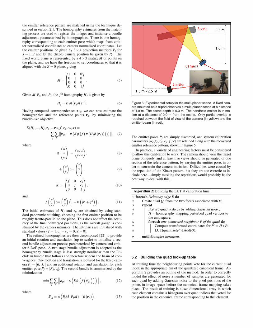
Figure 6: Experimental setup for the multi-planar scene. A fixed cam-era mounted on a tripod observes a multi-planar scene at a distanceof 1.0 m. The scene depth is 0.3 m. The handheld emitter is in mo-tion at a distance of 2.0 m from the scene. Only partial overlap isrequired between the field of view of the camera (in yellow) and theemitter beam (in red).
The emitter poses Pj are simply discarded, and system calibrationparameters (Rc, tc,cx,cy, f ,κ) are retained along with the recoveredemitter reference pattern, shown in figure 5.
In practice, a variety of engineering factors must be consideredto allow this calibration to work. The camera should view the targetplane obliquely, and at least five views should be generated of onesection of the reference pattern, by varying the emitter pose, in or-der to constrain the camera intrinsics. Difficulties were caused bythe repetition of the Kinect pattern, but they are too esoteric to in-clude here—simply masking the repetitions would probably be thebest way to deal with this.
Algorithm 2: Building the LUT at calibration time.
1 foreach Delaunay edge E do2 Create quad Q′ from the two facets associated with E;3 repeat4 Perturb quad vertices by adding Gaussian noise;5 H = homography mapping perturbed quad vertices to
the unit square;6 foreach one-connected neighbour P of the quad do7 Compute transformed coordinates for P′ = H ∗P;8 LUT[quantize(P′)].Add(Q);
9 until #samples iterations;
5.2 Building the quad look-up table
At training time the neighbouring points vote for the current quadindex in the appropriate bin of the quantized canonical frame. Al-gorithm 2 provides an outline of the method. In order to correctlymodel the effect of noise a number of samples are generated foreach quad by adding Gaussian noise to the pixel positions of thepoints in image space before the canonical frame mapping takesplace. The result of training is a two dimensional array in whicheach element contains a histogram over quad indices that voted forthe position in the canonical frame corresponding to that element.
6 EXPERIMENTS
The system as described above has been implemented, and we showtwo examples of its performance: a qualitative demonstration of itsuse as a 6-DoF input device, and quantitative comparisons with aVicon tracker. Experiments run on an Intel Core i7 desktop witha 640x480 1/4” CCD monochrome camera, 6mm lens and an IRbandpass filter. The camera is mounted on a tripod and observesa planar or multi-planar scene at a distance of 1.0 m, with a planeseparation of 0.3 m in the multi-planar case. The Kinect emitter isheld by the user, operating at a distance of 1.5 m – 2.5 m from thescene. Figure 6 shows the experimental setup.
6.1 Emitter as user interface deviceThe supplementary material [15] shows a user moving the deviceto control a virtual light sabre (four frames are shown in figure 7).As can be observed, translational and rotational accuracy are com-parable to other look-out systems, with a much smaller and simplerdevice. As shown in the video our system can robustly track thepointing device in real-time.
6.2 Comparison to ViconIn figure 8 we show a 140-frame test sequence of Kinectrack com-pared to the Vicon tracking system, which is taken as ground truth.Translation accuracy was found to be 1.86 cm RMS error, withRMS error in rotation of 1.29◦. This shows that at a greatly reducedcost, setup time, and with only a single camera, adequate trackingcan be achieved when compared to a commercially available andexpensive multi-camera system.
Figure 9 shows results for scene geometry restricted to a singleplane. The accuracy of the pose estimate is reduced, particularlywith respect to translation, but it remains sufficient for many ap-plications involving 3D user interaction with planar scenes. Themotion trajectories for the Vicon (plotted in red) when compared tothe Kinectrack system (plotted in blue) are shown in figure 10 forboth multi- and single-planar scene geometry.
7 CONSTRAINTS AND LIMITATIONS
The proposed method requires a camera to be fixed relative to thescene, which prevents the use of the system for free AR applica-tions where the user is permitted to move anywhere. The advantageof a fixed camera is that it prevents the drift problem suffered bySLAM systems by providing absolute pose every frame, even whenthe scene geometry is not static. As outlined in section 5, the place-ment of the fixed camera is flexible and the emitter and camera in-trinsics may be pre-calibrated, so that only the external camera poseremains to be determined once the camera has been repositioned.
The emitter beam must partially overlap at all times with somepart of the scene in the camera’s field of view. The emitter mustbe designed with a wide beam spread to provide sufficient rangeof movement (in the case of the Kinect sensor the diagonal fieldof view is 70◦). The method is readily extended with either mul-tiple fixed cameras or multiple emitters on the device to providefull 360◦ coverage. Full 360◦ is available in one axis using a singlecamera by suitable choice of emitter and camera placement. For ex-ample, projecting the dot pattern onto the floor or ceiling achievesfull 360◦ freedom in terms of pan, with only tilt and roll restrictedby the emitter beam spread. By using a dense dot pattern and onlyrequiring a small part of that pattern to be visible in order to deter-mine the emitter pose, the system is made robust to occlusion, non-planar scenes and varying surface albedo. The scene must containsome quasi-planar structure for the matching algorithm to succeed,but the surface need only be locally flat. Examples of sufficientlyquasi-planar surfaces tested include a beach ball and a round teapot.Robustness to varying surface albedo is important as whilst the Ki-netic dot pattern is clearly visible on most surfaces, some surfacespresent more of a challenge, such as shiny or translucent plastics.
0 20 40 60 80 100 120 140
−0.04
−0.02
0
0.02
Frame
Tra
nsla
tion
[m]
X Y Z
0 20 40 60 80 100 120 140
−0.05
0
0.05
Frame
Rot
atio
n [r
ad]
ROLL PITCH YAW
Figure 8: Comparison to Vicon with multi-planar scene geometry:Translation (top) and rotation (bottom) performance for a 140-framesequence (RMS error is 1.86 cm in translation and 1.29◦ in rotation.)
0 10 20 30 40 50 60 70 80−0.1
−0.05
0
0.05
0.1
Frame
Tra
nsla
tion
[m]
X Y Z
0 10 20 30 40 50 60 70 80−0.1
−0.05
0
0.05
0.1
Frame
Rot
atio
n [r
ad]
ROLL PITCH YAW
Figure 9: Comparison to Vicon with single-planar scene geometry:Translation (top) and rotation (bottom) errors for an 80-frame se-quence (RMS error is 3.08 cm in translation and 1.53◦ in rotation.)
Figure 10: Qualitative comparison of Vicon (red) and Kinectrack(blue) trajectories with recovered multi-planar (left) and single-planar(right) scene geometry.
The distance of both the camera and emitter from the scene de-termines the density of the dot pattern in the image. If the emitteris too close or the camera too far away, the quads become too smalland matching fails due to the increase in noise relative to the canon-ical frame. Conversely, if the emitter is too far or the camera istoo close, matching fails due to insufficient dots on any one quasi-planar surface for matching. Emitter pose accuracy also degradeswith distance relative to the scene as the emitter beam angle sub-tended by the camera image decreases. In practice, the emitter dotpattern could be chosen to achieve the optimal image dot densityfor the emitter and camera positions required by the application.
The use of active illumination also poses some restrictions. As
Figure 7: Example application. A user holding the emitter is augmented in an RGB camera view with a light sabre. The coordinate axes of thecamera observing the projected IR dot pattern are also shown.
with other projector-based systems, outdoor daytime use is limiteddue to laser strength. In our implementation we use the Kinectdevice to generate the dot pattern which has an optimal emitter-to-scene operating range of 1.2 m to 3.0 m. Performance degradesoutside this range as multiple overlapping dots appear in the imagedue to the laser DOE method used to form the dot pattern. An al-ternative dot pattern generator would enable use over other ranges.
8 CONCLUSIONS
We have introduced a new 6-DoF tracker and demonstrated a pre-liminary implementation, which shows that a computationally pas-sive tracking device can provide some of the benefits of a “look out”system as exemplified by SLAM coupled with some of the benefitsof “look in” systems such as Vicon. In particular, the system is lowcost and low effort to deploy, is robust to different piecewise planarscene structures and works in texture-less environments and low-lighting. It provides absolute pose with good tracking accuracy andno drift over time.
Our system currently assumes a planar scene for its calibrationstage, which simplifies the construction of the reference pattern,but probably reduces the calibration quality away from the targetplane. It would be interesting to see how a more 3D scene affectsthe results. We also have the option to improve translational accu-racy further in cases where the reference camera can see the deviceitself. Alternatively a second room camera can be used.
Overall we feel that Kinectrack provides an interesting newtracking technology for AR, it is cheap, robust to lighting, supportsa variety of piecewise planar scene structures, recovers scene geom-etry and is easy to implement for real-time performance. We alsofeel that the variable baseline matching algorithm described here isgeneral and can be used in other scenarios to find correspondencebetween two frames of a pseudo random dot image.
REFERENCES
[1] B. Ahlborn, D. Thompson, O. Kreylos, B. Hamann, and O. G. Staadt.A practical system for laser pointer interaction on large displays. InProc. ACM Symp. Virtual Reality Software and Technology, 2005.
[2] I. Albitar, P. Graebling, and C. Doignon. Robust structured light cod-ing for 3d reconstruction. In Computer Vision, 2007. ICCV 2007.IEEE 11th International Conference on, pages 1–6. Ieee, 2007.
[3] D. Cavens, F. Vogt, S. Fels, and M. Meitner. Interacting with the bigscreen: pointers to ponder. Human Performance, page 678, 2002.
[4] L. Chan, H. Wu, H. Kao, J. Ko, H. Lin, M. Y. Chen, J. Hsu, andY. Hung. Enabling Beyond-Surface Interactions for Interactive Sur-face with An Invisible Projection. Glass, pages 263–272, 2010.
[5] J. Davis and X. Chen. Lumipoint: multi-user laser-based interactionon large tiled displays. Displays, 23(5):205–211, 2002.
[6] A. Davison, I. Reid, N. Molton, and O. Stasse. MonoSLAM: Real-time single camera SLAM. IEEE Transactions on Pattern Analysisand Machine Intelligence, 29(6):1052, 2007.
[7] M. Fiala. ARTag, a Fiducial Marker System Using Digital Techniques.In Proc. IEEE Computer Vision and Pattern Recognition, 2005.
[8] R. Hartley and A. Zisserman. Multiple View Geometry in ComputerVision. Cambridge University Press, second edition, 2004.
[9] H. Kato and M. Billinghurst. Marker tracking and HMD calibrationfor a video-based augmented reality conferencing system. In Proc.IEEE and ACM International Workshop on Augmented Reality, 1999.
[10] G. Klein and D. Murray. Parallel tracking and mapping for small ARworkspaces. In Proc. IEEE and ACM International Symposium onMixed and Augmented Reality, 2007.
[11] M. Kolomenkin, S. Pollak, I. Shimshoni, and M. Lindenbaum. Ge-ometric voting algorithm for star trackers. IEEE Transactions OnAerospace And Electronic Systems, 44(2):441–456, 2008.
[12] D. Lang, D. Hogg, K. Mierle, M. Blanton, and S. Roweis. Astrom-etry .net: Blind astrometric calibration of arbitrary astronomical im-ages. The Astronomical Journal, 139:1782, 2010.
[13] M. E. Latoschik and E. Bomberg. Augmenting a Laser Pointer witha Diffraction Grating for Monoscopic 6DOF Detection. Journal ofVirtual Reality and Broadcasting, 4(14):1860–2037, 2007.
[14] S. V. Matveyev and M. Gobel. The Optical Tweezers: Multiple-PointInteraction Technique. In Proc. ACM Symposium on Virtual RealitySoftware and Technology, page 184, 2003.
[15] P. M. McIlroy, S. Izadi, and A. W. Fitzgibbon. Supplementary mate-rial. http://research.microsoft.com/kinectrack, 2012.
[16] T. Nakai, K. Kise, and M. Iwamura. Use of affine invariants in lo-cally likely arrangement hashing for camera-based document imageretrieval. Document Analysis Systems VII, pages 541–522, 2006.
[17] NaturalPoint. Optitrack tracking. http://naturalpoint.com/optitrack.[18] D. Nister. An efficient solution to the five-point relative pose problem.
In Proc. IEEE Computer Vision and Pattern Recognition, 2003.[19] OpenCV.org. Opencv v2.4 documentation.[20] Y. Qin, Y. Shi, and H. Jiang. Structured laser pointer: enabling wrist-
rolling movements as a new interactive dimension. In Proc. Interna-tional Conference on Advanced Visual Interfaces, 2010.
[21] T. Shiratori, H. Park, L. Sigal, Y. Sheikh, and J. Hodgins. Motioncapture from body-mounted cameras. ACM Transactions on Graphics,30(4):31, 2011.
[22] G. Simon, A. Fitzgibbon, and A. Zisserman. Markerless tracking us-ing planar structures in the scene. In Proc. IEEE and ACM Interna-tional Symposium on Augmented Reality, 2000.
[23] H. Uchiyama and E. Marchand. Deformable random dot markers. InProc. IEEE Int. Symposium on Mixed and Augmented Reality, 2011.
[24] H. Uchiyama and H. Saito. Random dot markers. In IEEE VirtualReality Conference, 2011.
[25] Vicon.com. Vicon. http://www.vicon.com/.[26] C. Wienss, I. Nikitin, G. Goebbels, and K. Troche. Sceptre: an in-
frared laser tracking system for virtual environments. In Proc. ACMSymposium on Virtual Reality Software and Technology, 2006.
[27] O. Williams and A. Fitzgibbon. Optical pointing device. US PatentApplication US2009/0237356 A1, Sep. 2009.
[28] K. Willis, I. Poupyrev, S. Hudson, and M. Mahler. SideBySide: ad-hoc multi-user interaction with handheld projectors. In Proc. ACMSymposium on User Interface Software and Technology, 2011.
[29] D. Wormell, E. Foxlin, and P. Katzman. Advanced inertial-opticaltracking system for wide area mixed and augmented reality systems.In Proc. Eurographics Workshop on Virtual Environments, 2007.