12
MTN MTN KP MINI KP MINI CONTROL KP MINI KP MINI CONTROL KP MINI KP MINI CONTROL Electric Part-turn Actuator Type No. 52 997, 52 998 KP MINI - A KP MINI - A KP MINI A 1/05
MTN
MTN
KP MINIKP MINI CONTROL
KP MINIKP MINI CONTROL
KP MINIKP MINI CONTROL
E l e c t r i c P a r t - t u r n A c t u a t o r
Ty p e N o . 5 2 9 9 7 , 5 2 9 9 8
KP MINI - A
KPMINI - AKP MINI A 1/05

3
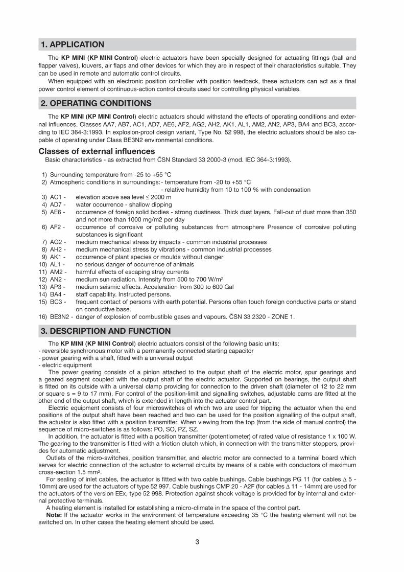
1. APPLICATION
The KP MINI (KP MINI Control) electric actuators have been specially designed for actuating fittings (ball andflapper valves), louvers, air flaps and other devices for which they are in respect of their characteristics suitable. Theycan be used in remote and automatic control circuits.
When equipped with an electronic position controller with position feedback, these actuators can act as a final power control element of continuous-action control circuits used for controlling physical variables.
2. OPERATING CONDITIONS
The KP MINI (KP MINI Control) electric actuators should withstand the effects of operating conditions and exter-nal influences, Classes AA7, AB7, AC1, AD7, AE6, AF2, AG2, AH2, AK1, AL1, AM2, AN2, AP3, BA4 and BC3, accor-ding to IEC 364-3:1993. In explosion-proof design variant, Type No. 52 998, the electric actuators should be also ca-pable of operating under Class BE3N2 environmental conditions.
Classes of external influencesBasic characteristics - as extracted from ČSN Standard 33 2000-3 (mod. IEC 364-3:1993).
1) Surrounding temperature from -25 to +55 °C 2) Atmospheric conditions in surroundings:- temperature from -20 to +55 °C
- relative humidity from 10 to 100 % with condensation3) AC1 - elevation above sea level ≤ 2000 m4) AD7 - water occurrence - shallow dipping5) AE6 - occurrence of foreign solid bodies - strong dustiness. Thick dust layers. Fall-out of dust more than 350
and not more than 1000 mg/m2 per day6) AF2 - occurrence of corrosive or polluting substances from atmosphere Presence of corrosive polluting
substances is significant7) AG2 - medium mechanical stress by impacts - common industrial processes8) AH2 - medium mechanical stress by vibrations - common industrial processes9) AK1 - occurrence of plant species or moulds without danger
10) AL1 - no serious danger of occurrence of animals11) AM2 - harmful effects of escaping stray currents12) AN2 - medium sun radiation. Intensity from 500 to 700 W/m2
13) AP3 - medium seismic effects. Acceleration from 300 to 600 Gal14) BA4 - staff capability. Instructed persons. 15) BC3 - frequent contact of persons with earth potential. Persons often touch foreign conductive parts or stand
on conductive base.16) BE3N2 - danger of explosion of combustible gases and vapours. ČSN 33 2320 - ZONE 1.
3. DESCRIPTION AND FUNCTION
The KP MINI (KP MINI Control) electric actuators consist of the following basic units:- reversible synchronous motor with a permanently connected starting capacitor- power gearing with a shaft, fitted with a universal output- electric equipment
The power gearing consists of a pinion attached to the output shaft of the electric motor, spur gearings and a geared segment coupled with the output shaft of the electric actuator. Supported on bearings, the output shaft is fitted on its outside with a universal clamp providing for connection to the driven shaft (diameter of 12 to 22 mm or square s = 9 to 17 mm). For control of the position-limit and signalling switches, adjustable cams are fitted at the other end of the output shaft, which is extended in length into the actuator control part.
Electric equipment consists of four microswitches of which two are used for tripping the actuator when the end positions of the output shaft have been reached and two can be used for the position signalling of the output shaft, the actuator is also fitted with a position transmitter. When viewing from the top (from the side of manual control) thesequence of micro-switches is as follows: PO, SO, PZ, SZ.
In addition, the actuator is fitted with a position transmitter (potentiometer) of rated value of resistance 1 x 100 W.The gearing to the transmitter is fitted with a friction clutch which, in connection with the transmitter stoppers, provi-des for automatic adjustment.
Outlets of the micro-switches, position transmitter, and electric motor are connected to a terminal board whichserves for electric connection of the actuator to external circuits by means of a cable with conductors of maximumcross-section 1.5 mm2.
For sealing of inlet cables, the actuator is fitted with two cable bushings. Cable bushings PG 11 (for cables ∆ 5 -10mm) are used for the actuators of type 52 997. Cable bushings CMP 20 - A2F (for cables ∆ 11 - 14mm) are used forthe actuators of the version EEx, type 52 998. Protection against shock voltage is provided for by internal and exter-nal protective terminals.
A heating element is installed for establishing a micro-climate in the space of the control part.Note: If the actuator works in the environment of temperature exceeding 35 °C the heating element will not be
switched on. In other cases the heating element should be used.

4
4. TECHNICAL PARAMETERS
Basic technical parameters - table of design variants
1 x x x3 x x x5 x x x2 x x x4 x x x6 x x x7 x x x8 x x x
x x x 4x x x 5x x x 6x x x 7x 1 x xx 2 x xx 3 x xx 4 x x
230 V24 V
110 V230 V24 V
110 V120 V24 V
Frequency, supply voltage
Position transmitter - Electronic position transmitter ZP 2.RE
with position transmitter 1x100Ω
without position transmitterwith position transmitter 2x100Ω
union flange size
AC 50 Hz
AC 60 Hz
DC
52 997(52 998)
52 997(52 998)
without controllerwith controller
without controllerwith controller
flange F03flange F04flange F05flange F07
Type Rated torque[Nm]
Workingstroke
[°]
Adjusting time (90°)[s]
Electric motor Type number
basic supplementary
x x 1 xx x 2 xx x 3 xx x 4 xx x 5 xx x 8 x
SMRSMRSMRSMRITTITT
306090120
487296
64-887
402.907403.903
9030KP MINI
(EEx)
300/1200300/800300/600
300/1200 300/1200300/600300/600
52 997(52 998)
52 997
50 HzDC DC AC 50Hz AC 60Hz60 Hz Typ
Additional technical parameters
Duty: S2 - 10 min.; S4 - 30% - 1,200 cycles/hourWeight: 4 kgOutput shaft play: 1.5°Insulation resistance: at least 20 MΩ under dry condition;
at least 2 MΩ after a damp testActuator life: at least 1x10⁶ operations with a running time of 0.75 s at the rated torqueDesign in respect of explosion-proofness: standard design - Type No. 52 997 (BNV - according to ČSN 33 2320)
explosion-proof design EExd II CT 6 - Type No. 52 998Noise: acoustic pressure level A does not exceed 75 dB (A).
acoustic power level A does not exceed 85 dB (A).Protective enclosure: IP 67

5
Technical parameters of the electric motors used
Type of electric motor Power[W]
Supply voltage[V]
Frequency[Hz]
Current[A]
506050605060506050605060506050605060--
0,0680,0780,1610,1770,6150,680,0460,050,0870,0960,520,570,0360,0390,0720,0780,3100,3500,25
1
230
110
24
230
110
24
230
110
24
3,8
2,5
1,9
SMR 300 - 1200
SMR 300 - 800
SMR 300 - 600
ITT 402.907ITT 403.903
2,516
24 DC24 DC
Basic electric equipment: 2 position-limit switches (OPEN and CLOSE)2 signalling switches (OPEN and CLOSE)1 synchronous motor2 cable bushings1 terminal board1 anti-condensation heater
Additional electric equipment (according to the customer’s requirements): 1 electronic position controller1 resistance position transmitter
6
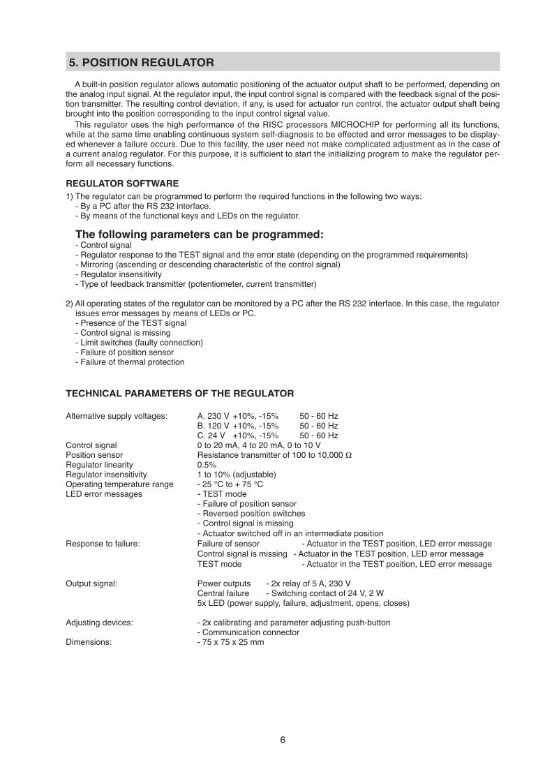
5. POSITION REGULATOR
A built-in position regulator allows automatic positioning of the actuator output shaft to be performed, depending onthe analog input signal. At the regulator input, the input control signal is compared with the feedback signal of the posi-tion transmitter. The resulting control deviation, if any, is used for actuator run control, the actuator output shaft beingbrought into the position corresponding to the input control signal value.
This regulator uses the high performance of the RISC processors MICROCHIP for performing all its functions,while at the same time enabling continuous system self-diagnosis to be effected and error messages to be display-ed whenever a failure occurs. Due to this facility, the user need not make complicated adjustment as in the case ofa current analog regulator. For this purpose, it is sufficient to start the initializing program to make the regulator per-form all necessary functions.
REGULATOR SOFTWARE
1) The regulator can be programmed to perform the required functions in the following two ways:- By a PC after the RS 232 interface.- By means of the functional keys and LEDs on the regulator.
The following parameters can be programmed:- Control signal- Regulator response to the TEST signal and the error state (depending on the programmed requirements)- Mirroring (ascending or descending characteristic of the control signal)- Regulator insensitivity- Type of feedback transmitter (potentiometer, current transmitter)
2) All operating states of the regulator can be monitored by a PC after the RS 232 interface. In this case, the regulatorissues error messages by means of LEDs or PC.- Presence of the TEST signal- Control signal is missing- Limit switches (faulty connection)- Failure of position sensor- Failure of thermal protection
TECHNICAL PARAMETERS OF THE REGULATOR
Alternative supply voltages: A. 230 V +10%, -15% 50 - 60 HzB. 120 V +10%, -15% 50 - 60 HzC. 24 V +10%, -15% 50 - 60 Hz
Control signal 0 to 20 mA, 4 to 20 mA, 0 to 10 VPosition sensor Resistance transmitter of 100 to 10,000 ΩRegulator linearity 0.5%Regulator insensitivity 1 to 10% (adjustable)Operating temperature range - 25 °C to + 75 °CLED error messages - TEST mode
- Failure of position sensor- Reversed position switches- Control signal is missing- Actuator switched off in an intermediate position
Response to failure: Failure of sensor - Actuator in the TEST position, LED error messageControl signal is missing - Actuator in the TEST position, LED error messageTEST mode - Actuator in the TEST position, LED error message
Output signal: Power outputs - 2x relay of 5 A, 230 VCentral failure - Switching contact of 24 V, 2 W5x LED (power supply, failure, adjustment, opens, closes)
Adjusting devices: - 2x calibrating and parameter adjusting push-button- Communication connector
Dimensions: - 75 x 75 x 25 mm

7
Dimensional sketch of the KP MINI electric actuators, Type No. 52 997, 52 998design with flange F03, F04, F05 (actuator in OPEN position)
∅ d5
∅ d2
∅ d3
70 ±0,1
∅ 80
9 22
2∅ d4
26
2xP11 (52 997)
2xCMP 20 (52 998)202
40 35
160
d7
„O“
(„Z“)
45
45
160
only Type No. 52 997
202
40 35
160
26
9
22
2
2xP11 (52 997)
2cCMP 20 (52 998)
(„C“)
„O“
DimensionFlange
FO3FO4FO5
d2253035
d3364250
d4M5M5M6
d5202528
s9–149–179–17
d712–2012–2212–22
Connecting dimensions for actuator connection to a fitting(any other connection should be consulted with the manufacturer beforehand).

8
Dimensional sketch of the KP MINI electric actuators, Type No. 52 997, 52 998design with flange F07 (actuator in OPEN position)
20
0
2xP11 (52 997)2xCMP 20 (52 998)
∅ d3
∅ d4
92
2 26
only Type No. 52 997
40 35
160
”C“
”O“
160
45
45
d7
DimensionFlange
FO7d2-
d370
d4M8
d5-
s9–17
d712–22
Connecting dimensions for actuator connection to a fitting(any other connection should be consulted with the manufacturer beforehand).

9
KP MINI electric actuator, Type No. 52 997- with one-phase motor and resistance position transmitter
or withouth transmitter
KP MINI Control electric actuator, Type No. 52 997- with one-phase motor
and resistance position transmitter
P-0777 P-0787
KP MINI EEx electric actuator, Type No. 52 998- with one-phase motor and resistance position transmitter
or withouth transmitter
KP MINI EEx electric actuator, Type No. 52 998- with one-phase motor supplied by direct current
and with resistance position transmitter or withouthtransmitter
P-0853 P-0854
Internal wiring diagrams of the KP MINI electric actuators
10
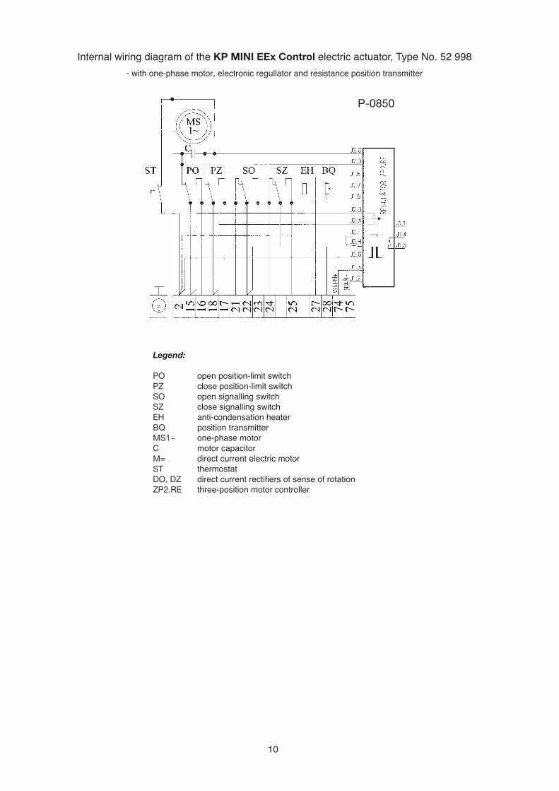
Internal wiring diagram of the KP MINI EEx Control electric actuator, Type No. 52 998- with one-phase motor, electronic regullator and resistance position transmitter
Legend:
PO open position-limit switchPZ close position-limit switchSO open signalling switchSZ close signalling switchEH anti-condensation heaterBQ position transmitterMS1~ one-phase motorC motor capacitorM= direct current electric motor ST thermostatDO, DZ direct current rectifiers of sense of rotationZP2.RE three-position motor controller
P-0850
TTRRAADD
IITTIIOONN
QQUUAALL
IITTYY
RREELLIIAA
BBIILLIITTYY
Deliveries of assembled actuator + fitting (or MASTERGEAR gearbox) combinations
SURVEY OF PRODUCED ACTUATORSKP Mini
Electric part-turn actuators (up to 30 Nm)
Modact MOK, MOK-P, MOK-P EExElectric part-turn actuators for ball valves and flaps
Modact MONElectric multi-turn actuators
Modact MO EExExplosion proof electric multi-turn actuators
Modact MOAElectric part-turn actuators for nuclear power stations
application outside containment
Modact MOA OCElectric multi-turn actuators for nuclear power stations
application inside containment
Modact Variant MPRElectric part-turn lever actuators with a variable output speed
Modact Konstant MPSElectric part-turn lever actuators with a constant output speed
Modact MTNElectric linear thrust actuators with a constant output speed
Electr ic actuators and swi tchboardsDevelopment, production, sales, services

tř. 5. května 166289 11 PEČKY, Czech Republice-mail: [email protected]
tel.: +420 321 785 141-9fax: +420 321 785 165
+420 321 785 167

![Pressure switches and Thermostats, type KP · Dimensions [in] KP 35, KP 36 and KP 37 KP 34 Approximate weight: 0.83 lb Approximate weight: 0.9 lb Design and function Key sketch of](https://static.documents.pub/doc/80x56/5e8321e1a01b552dac753adc/pressure-switches-and-thermostats-type-kp-dimensions-in-kp-35-kp-36-and-kp-37.jpg)


